UT715 - Measurement Uni-T - Free user manual and instructions
Find the device manual for free UT715 Uni-T in PDF.

| Product Type | Digital Multimeter |
| Brand | Uni-T |
| Model | UT715 |
| Category | Measurement |
| Dimensions | Approximately 180 x 85 x 40 mm |
| Weight | Approximately 200 g (including battery) |
| Power Supply | 9V battery (e.g., NEDA 1604, 6F22) |
| Display | Digital LCD with backlight |
| DC Voltage Range | 200 mV to 1000 V |
| AC Voltage Range | 200 mV to 750 V |
| DC Current Range | 200 μA to 10 A |
| Resistance Range | 200 Ω to 20 MΩ |
| Capacitance Measurement | Yes, up to 100 μF |
| Frequency Measurement | Up to 20 kHz |
| Continuity Test | Built-in buzzer |
| Diode Test | Yes |
| Safety Rating | CAT II 1000 V, CAT III 600 V |
| Overload Protection | Fuse for current ranges |
| Auto Power Off | Yes, after 15 minutes of inactivity |
| Data Hold | Yes |
| Relative Mode | Yes |
| Maintenance | Clean with a dry cloth; do not use liquids |
| Accessories Included | Test leads, battery, user manual |
Frequently Asked Questions - UT715 Uni-T
User questions about UT715 Uni-T
0 question about this device. Answer the ones you know or ask your own.
Ask a new question about this device
Download the instructions for your Measurement in PDF format for free! Find your manual UT715 - Uni-T and take your electronic device back in hand. On this page are published all the documents necessary for the use of your device. UT715 by Uni-T.
USER MANUAL UT715 Uni-T
natural_image
Abstract geometric pattern composed of gray squares forming a symmetrical shape (no text or symbols)
P/N:110401109797X
UNI-T®


text_image
24.000mA SOURCE SEM SEM SEM SEM SEM SEM SEM SEM SEM SEM SEM SEM SEM SEM SEM SEM SEM SEM SEM SEM SEM SEM SEM SEM SEM SEM SEM SEM SEM SEM SEM SEM SEM SEM SEM SEM SEM SEM SEM SEM SEM SEM SEM SEM SEM SEM SEM SEM SEM SEM SemiconductorUT715
Multifunction
Loop Process
Calibrator
Preface
Thank you for purchasing this brand new product. In order to use this product safely and correctly, please read this manual thoroughly, especially the safety notes.
After reading this manual, it is recommended to keep the manual at an easily accessible place, preferably close to the device, for future reference.
Limited Warranty and Liability
Uni-Trend guarantees that the product is free from any defect in material and workmanship within one year from the purchase date. This warranty does not apply to damages caused by accident, negligence, misuse, modification, contamination or improper handling. The dealer shall not be entitled to give any other warranty on behalf of Uni-Trend. If you need warranty service within the warranty period, please contact your seller directly.
Uni-Trend will not be responsible for any special, indirect, incidental or subsequent damage or loss caused by using this device.
UNI-T®
UT715 User Manual
Content
- Overview 3
- Accessories 4
- Symbol 7
- Specification 7
- Structure 8
- LCD Display 11
- Operation 11
- Measurement Mode 13
- Remote mode 19
- Advanced application 20
- Indicator 22
- Maintenance 24
UNI-T®
UT715 User Manual
1. Overview
UT715 is a high-performance, high-accuracy, handheld, multifunctional loop calibrator, which can be used in loop calibration and repair. It can output and measure direct current and voltage with a high accuracy of 0.02%, it has the functionalities of automatic stepping and automatic sloping output, these functionality help you to rapidly detect the linearity, the storage functionality facilitates the system setup, the data transferring functionality help the customers to rapidly test the communication.
Chart 1 Input and output function
| Function | Input | Output | Remark |
| DC millivolt | -10mV - 220mV | -10mV - 110mV | |
| DC Voltage | 0 – 30V | 0 – 10V | |
| DC Current | 0 – 24mA | 0 – 24mA | |
| 0 – 24 mA (LOOP) | 0 – 24mA (SIM) | ||
| Frequency | 1Hz - 100kHz | 0.20Hz - 20kHz | |
| Pulse | 1-10000Hz | The pulse quantity and range can be compiled. | |
| Continuity | 500Ω | The buzzer beeps when the resistance is less than 250Ω. | |
| 24V Power | 24V |
UNI-T®
UT715 User Manual
2. Features
a) The output accuracy and measurement accuracy reach up to 0.02%.
b) It can output "Percentage", users can easily get different percentage values by pressing button.
c) It has the functionality of automatic stepping and automatic sloping output, these functions help you to rapidly detect the linearity.
d) It can measure mA at the same time of providing the loop power to the transmitter.
e) It can save frequently-used setting status.
f) The data transferring function helps you to rapidly test the communication.
g) Adjustable screen brightness.
h) Rechargeable Ni-MH battery.
3. Accessories
If any of accessories is missing or damaged, please contact your supplier.
-
UT715 1 piece
-
Probes 1 pair
-
Alligator clips 1 pair
-
Use Manual 1 piec
-
AA NI-MH battery 6 pieces
-
Adaptor 1 piece
-
USB cable 1 piece
8.Cloth bag 1 piece
UNI-T®
UT715 User Manual
UNI-T®
4. Operation
Please use the calibrator according to the user manual. "Warning" refers to potential hazard, "Attention" refers to the situation where would damage the calibrator or tested devices.
Warning
To avoid electric shock, damage, explosive gas ignition, please follow bellows:
- Please use the calibrator according to this manual.
- Check before use, please do not use a damaged calibrator.
- Check the connectivity and insulation of the test leads, replace any exposed test leads.
- When using the probes, user only hold the protection end of the probe.
- Do not exert a voltage with more than 30.0V on any terminals and earth line.
- If a voltage with more than 30.0V is applied on any terminals, the factory certificate will be out of effect, moreover, the device will be damaged permanently.
- Correct terminals, modes, ranges must be used when it is on output status.
- To prevent the tested device from being damaged, choose a correct mode before connecting the testing lead.
- When connecting the leads, first connect the COM test probe and then connect the other probe. While disconnecting the lead, first disconnect the conducted probe and then disconnect the COM probe.
• Do not open the calibrator case. - Before using the calibrator, please ensure that the battery door is tightly closed. Please refer the "Maintenance and Repair".
- When the battery power is insufficient, replace or charge the battery as soon as possible to avoid wrong reading value which may cause electric shock. Before opening the battery door, first remove the calibrator from "Dangerous Zone". Please refer "Maintenance and Repair".
- Disassemble the test leads of the calibrator before opening the battery door.
UT715 User Manual
- For CAT I, the standard definition of measurement is applicable to the circuit that does not directly connect to a power source.
- Specific replacement parts must be used when repairing the calibrators.
- The inside of the calibrator must be free from water.
- Before using the calibrator, input a voltage value to check if the operation is normal.
- Do not use the calibrator wherever there is explosive powder nearby.
- For battery, please refer to "Maintenance"
■ Remove the test leads before switching to other outputs.
Attention
To prevent the calibrator or the test device from being damaged :
- The correct terminals, modes, ranges must be used when it is on output status.
- When measuring and outputting current, correct earplug, functionality and ranges must be used.
UNI-T®
UT715 User Manual
5. Symbol
| Double insulated | |
| Warning |
6. Specification
- The maximum voltage between the terminal and earth line, or any two terminals is 30V.
- Range: manually
- Operating Temp.: -10°C \~ 55°C
- Storage Temp.: -20°C - 70°C
- Relative Humidity: ≤95%(0°C \~ 30°C), ≤75%(30°C \~ 40°C), ≤50%(40°C \~ 50°C)
- Altitude: 0 - 2000m
- Battery: AA Ni-MH battery1.2V×6 pieces
- Drop test: 1 meter
- Dimension: 224×104×63mm
- Weight: About 650g (Including batteries)
UNI-T®
UT715 User Manual
7. Structure
- Input terminal and Output terminal
Fig.1 and Fig. 2 Input and output terminal.

Figure 1
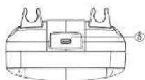
Figure 2
| No. | Name | Instruction |
| 1 2 | V, mV, Hz, -1, PULSE Measurement/Output Port | 1Connect red probe, 2Connect black probe |
| 2 3 | mA, SIM Measurement/Output Port | 3Connect red probe, 4Connect black probe. |
| 3 4 | LOOP Measurement Port | 4Connect red probe, 5Connect black probe. |
| 5 | Charge/Data Transfer Port | Connect to 12V-1A adaptor for recharging, or computer for data transmission |
UNI-T®
UT715 User Manual
2. Button
Fig.3 Calibrator button, Chart 4 Description.

text_image
1 2 3 4 5 6 7 8 9 10 11 12 13 14 15 16 17 18 19 20 Description.Figure 3
| 1 | Power or/off. Long press the button for 2s. | |
| 2 | Backlight adjustment. | |
| 3 | MEAS | Measurement Mode. |
9
UNI-T®
UT715 User Manual
| 4 | SOURCE | Mode selection. |
| 5 | V | Voltage measurement/output. |
| 6 | mV | Millivolt measurement/output. |
| 7 | mA | Milliampere measurement/output. |
| 8 | Hz | Short press the button to choose frequency measurement/output. |
| 9 | -1) | "Continuity Test". |
| 10 | PULSE | Short press the button to choose pulse output. |
| 11 | 100% | Short press to output the 100% value of the currently-set range,long press to reset the 100% values. |
| 12 | ▲25% | Short press to increase 25% of the range. |
| 13 | ▼25% | Short press to decrease 25% of the range. |
| 14 | 0% | Short press to output 0% value of the currently-set range,long press to reset the 0% value. |
| 15 | ◄▲▼► | Arrow key. Adjust the cursor and parameter. |
| 16 | AMF | Cycle selection:▲ Constantly output 0%-100%-0% at low slope (slow), repeat automatically,▼ Constantly output 0%-100%-0% at high slope (fast), repeat automatically,≠ At 25% of the step, step output 0%-100%-0%, repeat automatically. |
| 17 | RANGE | Switch range. |
| 18 | SETUP | Short press to set up the parameter, long press to enter Menu. |
| 19 | ESC | ESC |
10
UNI-T®
UT715 User Manual
- LCD Display
| Symbol | Description | Symbol | Description |
| SOURCE | Source output mode | Battery power | |
| MESUER | Measurement mode | LOAD | Overload |
| ▲ | Data adjustment prompt | AMF | Progress output, slope output, step output |
| SIM | Transmitter output simulation | PC | Remote control |
| LOOP | Loop measurement | APO | Auto power off |
9. Operation
This part introduces how to operate the UT715 calibrator.
-
Press ⏻ for more than 2s to power on, LCD will display the model number.
-
Long press [SETUP] to enter system setup menu. Press the arrow key to set parameter, short press ESC to exit the setup menu.

Figure 4 system setup
UNI-T®
UT715 User Manual
1) Auto power off:
Press ▼▲ to AUTO POWER OFF, press ◀▶ to set up the auto power off time. The AUTO POWER OFF time will start when no button is pressed, the counting will restart if any button is pressed. The max AUTO POWER OFF time is 60 minutes, '0' means auto power off is disabled.
2) Brightness:
Press ▼▲ to select the BRIGHTNESS, press◀▶ to adjust the screen brightness. Press 🔒 on setup menu to rapidly adjust the brightness.
3) Remote Control
Press ▼▲ to select REMOTE CONTROL, press ◀▶ to set up for remote PC control.
4) Button beep control
Press ▼▲ to select BEEP CONTROL, press ◀▶ to set up button sound. "Beep" once enables button sound, "Beep" twice disables button sound.
UNI-T®
UT715 User Manual
10. Measurement mode
If the calibrator is on 'Output' status, press MEAS to switch to measurement mode
1. Millivolt
Press mV to measure the millivolt. Measurement page shown in figure 5. Connection shown in Figure 6.

Figure 5 millivolt measurement

Figure 6 Connection
2. Voltage
Press V to measure the voltage. Measurement page shown in figure 7. Connection shown in Figure 8.
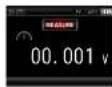
Figure 7 voltage measurement

Figure 8 Connection
UNI-T®
UT715 User Manual
3. Current
Constantly press mA until it is switched to measure the milliampere. Measurement page shown in figure 9. Connection shown in Figure 10.
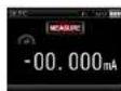
Figure 9 Continuity measurement

Figure 10 Connection
Note: The buzzer beeps once the resistance is less than 250Ω.
4. Loop
Constantly press mA until it is switched to measure the loop. Measurement page shown in figure 11. Connection shown in Figure 12.

Figure 11 Resistance measurement
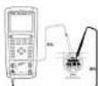
Figure 12 Connection
UNI-T®
UT715 User Manual
5. Frequency
Press Hz to measure the frequency. Measurement page shown in figure 13. Connection shown in Figure 14.
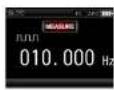
Figure 13 Frequency measurement
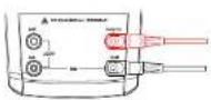
Figure 14 Connection
6. Continuity
Press ☐ to measure the continuity. Measurement page shown in figure 15. Connection shown in Figure 16.

Figure 15 Continuity Measurement

Figure 16 Connection
Note: The buzzer beeps once the resistance is less than 250Ω.
UNI-T®
UT715 User Manual
11. Source
Press SOURCE to switch to "Output Mode".
1. Millivolt
Press mV to select millivolt output. Millivolt output page shown in figure 17. Connection shown in figure 18. Press the arrow key (right & left) to choose output digit, press the arrow key (up & down) to set the value.

Figure 17 millivolt output
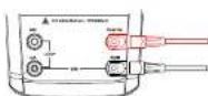
Figure 18 Connection
2. Voltage
Press V to select voltage output. Voltage output page shown in figure 19. Connection shown in figure 20. Press the arrow key (right & left) to choose output digit, press the arrow key (up & down) to set the value.
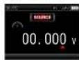
Figure 19 Voltage output
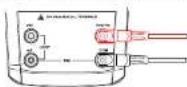
Figure 20 connection
UNI-T®
UT715 User Manual
3. Current
Press mA to select current output. Current output page shown in figure 21. Connection shown in figure 22. Press the arrow key (right & left) to choose output placement, press the arrow key (up & down) to set the value.

Figure 21 Current output

Figure 22 Connection
Note: If overload, the output value will flicker, the character "LOAD" will display, in this situation, you should check if the connection is correct for safety.
4. SIM
Press mA until the calibrator is switched to SIM Output. Passive current output shown in figure 23. Connection shown in 24, press the arrow key (right & left) to choose output placement, press the arrow key (up & down) to set the value.

Figure 23 Passive current output

Figure 24 Connection
UNI-T®
UT715 User Manual
Note: The output value will flicker and the character "LOAD" will display when the output is overload, please check if the connection is correct for safety.
5. Frequency
Press Hz to select frequency output. Frequency output shown in figure 25, connection shown in 26, press the arrow key (right & left) to choose output placement, press the arrow key (up & down) to set the value.
1) Press "RANGE" to choose different ranges (200Hz, 2000Hz, 20kHz).
2) Short Press SETUP to display frequency modification page, as figure 25, in this page, you can modify the frequency by pressing the arrow key. After modification, if you short press SETUP again, the modification will become effective. Short press ESC to give up the modification.

Figure 25 Frequency output
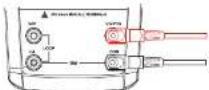
Figure 26 Connection
UNI-T®
UT715 User Manual
6.Pulse
Press PULSE to select frequency output, pulse output page shown in figure 27, connection shown in figure 28, press the arrow key (right & left) to choose output placement, press the arrow key (up & down) to set the value.
1) Press RANGE to choose different ranges (100Hz, 1kHz, 10kHz).
2) Short press SETUP, it will be on the status of editing pulse quantity, then press the arrow key to edit the pulse quantity, short press SETUP again to complete pulse quantity setting, soon after that, it will be on the status of editing pulse range, then you can press the arrow key to edit the pulse range, short press SETUP to complete pulse range modification. The calibrator will output a specific quantity of pulse at a set frequency and range.
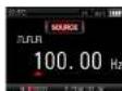
Figure 27 Pulse output

Figure 28 Connection
12. Remote mode
Based on the instruction, turn on the PC Control Functionality, set the parameter of serial interface on PC and send the protocol command to control UT715. Please refer "UT715 Communication Protocol".
UNI-T®
UT715 User Manual
13. Advanced application
1. Percentage
When the calibrator is on output mode, short press 0%, 100%, ▲25%, ▼25% to rapidly output percentage value accordingly, the 0% or 100% value of each output functionality is as below:
| Output Functionality | 0%value | 100%value |
| Millivolt 100mV | 0mV | 100mV |
| Millivolt 1000mV | 0mV | 1000mV |
| Voltage | 0V | 10V |
| Current | 4mA | 20mA |
| Frequency 200Hz | 0Hz | 200Hz |
| Frequency 2000Hz | 200Hz | 2000Hz |
| Frequency 20kHz | 2000Hz | 20000kHz |
The 0% or 100% value of each output can be reset by the following methods:
1) Press the arrow key to adjust the value and long press 100% until the buzzer beeps, a new 100% value will be set as output value.
2) Long press 0% until the buzzer beeps, a new 0% value will be set as output value.
UNI-T®
UT715 User Manual
Note: The 100% value must not be less than the 0% value.
Short press ▲25%, the output value will add 25% of the range between 100% value and 0% value.
Short press ▼25% the output value will decrease 25% range between 100% value and 0% value
Note: If you short press ▲25% or ▼25% to adjust the value of output functionality, the output value shall not be greater than the 100% value and not be less than 0% value.
2. Slope
The automatic output functionality of the slope can constantly provide a dynamic signal to the transmitter. If pressing _M , the calibrator will produce a constant and repeated slope (0%-100%-0%). There are 3 kinds of slope:
1) ∧ 0%-100%-0% 40 seconds, smooth slope.
2) M 0%-100%-0% 15 seconds, smooth slope.
3) 0%-100%-0% 25% progress slope, each step keeps for 5 seconds.
If you want to exit the slope functionality, please press any key except for the slope key.
UNI-T®
UT715 User Manual
14. Indicator
Unless otherwise specified, the calibration period of all indicators is one year, the applicable temperature is +18°C to +28°C, the warm-up time is assumed as 30 minutes.
- Input Indicator
| Indicator | Range | Resolution | Accuracy |
| DC voltage | 200mV | 0.01mV | ±(0.02%+5) |
| 30V | 1mV | ±(0.02%+2) | |
| DC current | 24mA | 0.001mA | ±(0.02%+2) |
| 24mA (LOOP) | 0.001mA | ±(0.02%+2) | |
| Frequency | 100Hz | 0.001Hz | ±(0.01%+1) |
| 1000Hz | 0.01Hz | ±(0.01%+1) | |
| 10kHz | 0.1Hz | ±(0.01%+1) | |
| 100kHz | 1Hz | ±(0.01%+1) | |
| Continuity detection | 500Ω | 1Ω | ≤slant 250Ω It beeps |
NOTE:
1) For those temperatures that are not within +18°C\~+28°C, the temperature coefficient of -10°C\~18°C and +28°C\~55°C is ±0.005%FS/°C.
2) The sensitivity of frequency measurement: Vp-p≥1V, waveform: Rectangular wave, sine wave, triangular wave, etc.
UNI-T®
UT715 User Manual
- Output indicator
| Indicator | Range | Resolution | Accuracy |
| DC voltage | 100mV | 0.01mV | ±(0.02% + 10) |
| 1000mV | 0.1mV | ±(0.02% + 10) | |
| 10V | 0.001V | ±(0.02% + 10) | |
| DC current | 20mA @ 0 - 24mA | 0.001mA | ±(0.02%+2) |
| 20mA(SIM) @ 0 - 24mA | 0.001mA | ±(0.02%+2) | |
| Frequency | 200Hz | 0.01Hz | ±(0.01%+1) |
| 2000Hz | 0.1Hz | ±(0.01%+1) | |
| 20kHz | 1Hz | ±(0.01%+1) | |
| Pulse | 1-100Hz | 1cyc | |
| 1-1000Hz | 1cyc | ||
| 1-10000Hz | 1cyc | ||
| Loop power supply | 24V | ±10% |
NOTE:
1) For those temperatures that are not within +18°C\~+28°C, the temperature coefficient of -10°C\~18°C and +28°C\~55°C is 0.005%FS/°C.
2) The max load of DC voltage output is 1mA or 10kΩ, the smaller load shall prevail.
3) The max resistance of DC output: 1000Ω@20mA.
23
UNI-T®
UT715 User Manual
15. Maintenance
Warning: Make sure that the power is off before opening the rear cover of the calibrator or battery cover, and that he probe is away from input terminal and tested circuit.
1. General maintenance and repair
Clean the case by damp cloth and mild detergent, do not use abrasives or solvents.
If there is any malfunction, stop using the calibrator and send it for repair.
Please ensure that the calibrator is repaired by professionals or designated repair center.
Calibrate the meter once a year to ensure its performance.
If the meter is not in use, turn off the power. If the meter is not in use for a long time, please take out the batteries.
Ensure that the instrumentation is free from moisture, high temperature and strong electromagnetic fields.
2. Install or replace the battery (Figure 29)
NOTE: When the battery power display, it means the rest of battery power is less than 20%, to ensure that the calibrator can work normally, please replace the battery in time, otherwise the measurement accuracy might be affected. Please replace the old battery by 1.5V alkaline battery or 1.2V NI-MH battery.
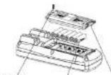
Screw
AA batteries
Figure 29
Battery cover
holder
UNI-T®
UT715 User Manual
UT715 User Manual
UNI-T®
UNI-T.
UNI-TREND TECHNOLOGY (CHINA) CO., LTD.
No.6. Gong Ye Bei 1st Road,
Songshan Lake National High-Tech Industrial
Development Zone, Dongguan City,
Guangdong Province, China
Made in China