OFS20 - Water dispenser OMEGA - Free user manual and instructions
Find the device manual for free OFS20 OMEGA in PDF.


| Product Type | Water Dispenser |
| Brand | Omega |
| Model | OFS20 |
| Dimensions (H x W x D) | Approx. 30 x 12 x 12 in (76 x 30 x 30 cm) |
| Weight | Approx. 15 lbs (6.8 kg) |
| Power Supply | 120V / 60Hz |
| Power Consumption | 500W (cooling) / 800W (heating) |
| Water Tank Capacity | 3.2 gallons (12 L) |
| Hot Water Temperature | 195°F - 205°F (90°C - 96°C) |
| Cold Water Temperature | 39°F - 50°F (4°C - 10°C) |
| Filtration System | Built-in carbon filter |
| Material | Stainless steel heating tank, plastic body |
| Safety Features | Child safety lock, automatic shutoff, overheat protection |
| Cleaning & Maintenance | Descale every 3 months; wipe exterior with damp cloth |
| Warranty | 1 year limited warranty |
| Spare Parts Availability | Drip tray, water tank, filter, heating element |
| Installation Type | Freestanding countertop |
| Water Input | Manual fill or optional bottle adapter |
Frequently Asked Questions - OFS20 OMEGA
User questions about OFS20 OMEGA
0 question about this device. Answer the ones you know or ask your own.
Ask a new question about this device
Download the instructions for your Water dispenser in PDF format for free! Find your manual OFS20 - OMEGA and take your electronic device back in hand. On this page are published all the documents necessary for the use of your device. OFS20 by OMEGA.
USER MANUAL OFS20 OMEGA
Eat well, drink well and live well with Omega
www.omegajuicers.com
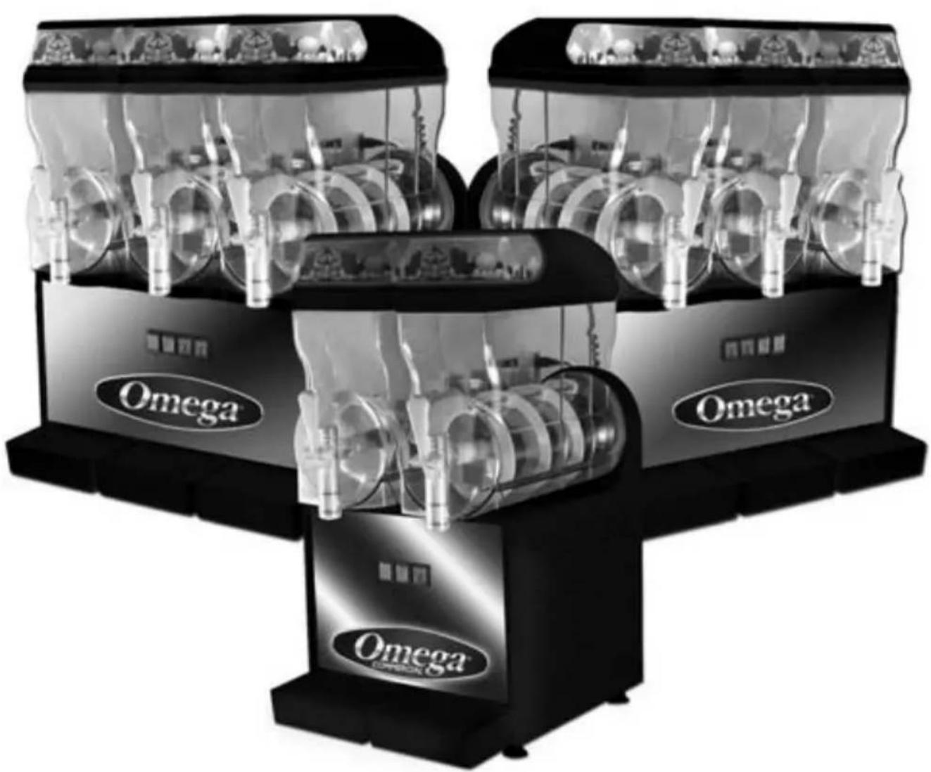
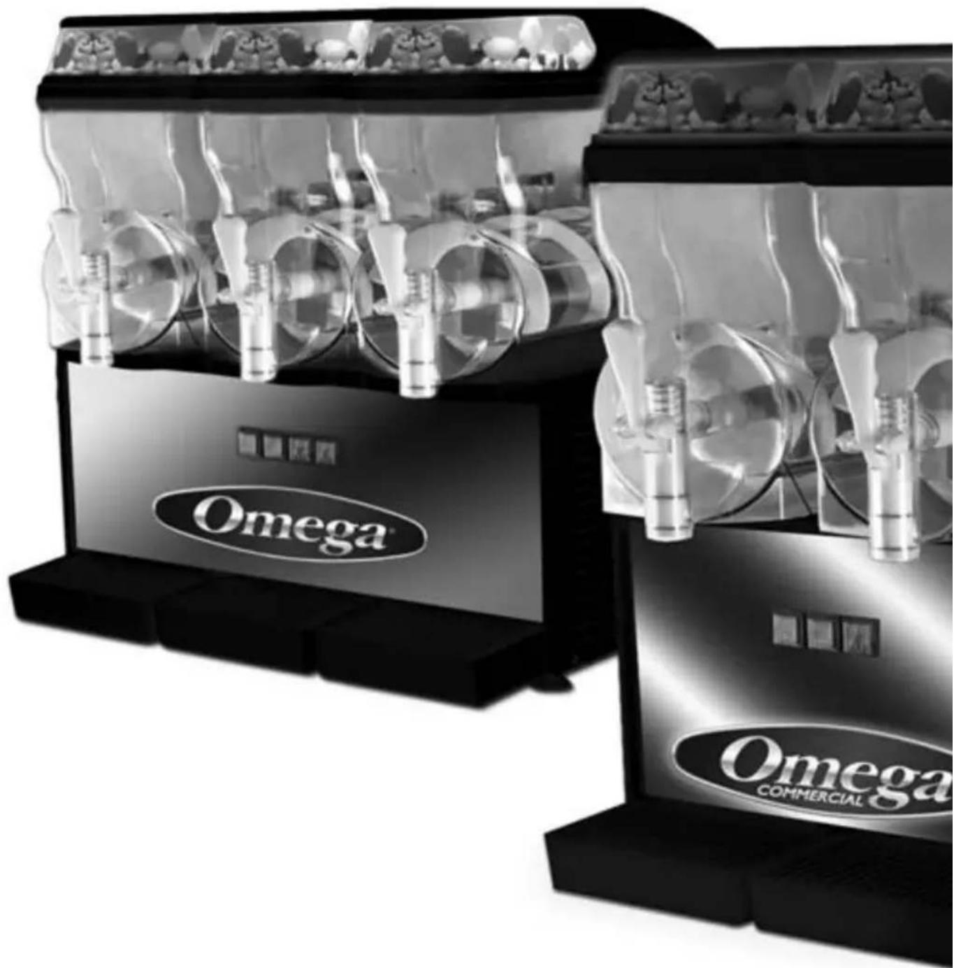
OFS20 & OFS30 GRANITA MACHINE
natural_image
Black and white photo of a multi-tiered Omega-branded coffee machine with transparent branding (no visible text or symbols on the machines themselves)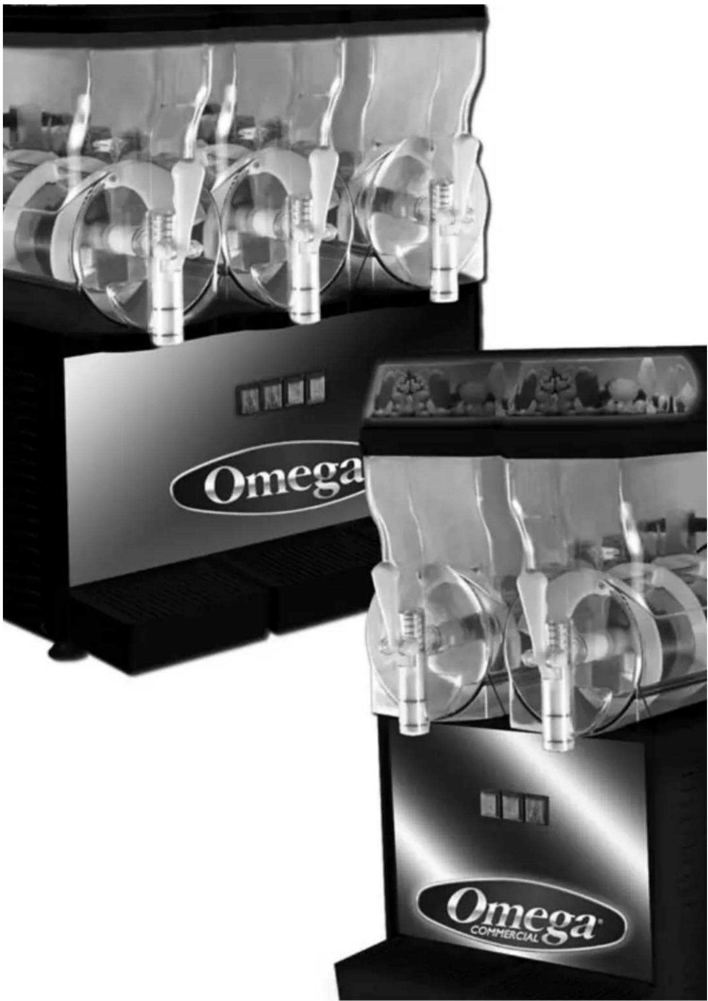
natural_image
Black-and-white photo of Omega Commercial coffee machines with transparent branding (no visible text or symbols on main subjects)TABLE OF CONTENTS
Specifications 3
Instructions for Machine Transport 4
Installation 4
Operating & Cleaning Procedures 5
Exploded View 8
Parts List 9-10
Electrical Diagram 11
Warranty 12
Specifications
natural_image
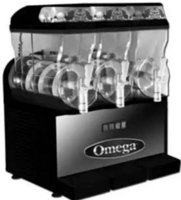
Black and white photo of a Omega coffee maker with transparent glass casing and multiple circular cavities (no visible text or symbols)OFS30
natural_image
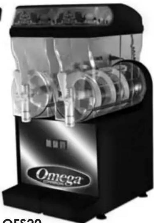
Black and white photo of a Omega brand coffee maker with transparent glass casing and mechanical components (no visible text or symbols)OFS20
OFS20
Dimensions: H 23in x W 17in x D 16in H 59cm x W 41cm x D 43cm
Watts: 710
OFS30
Dimensions H 23in x W 17in x D 24in H 59cm x W 41cm x D 61cm
Watts: 980
OFS20 Power Requirements:
Volts: 120/240VAC
Amps: 6 A/3 A
Hz: 50/60
OFS30 Power Requirements:
Volts: 120/240VAC
Amps: 8 A/4 A
Hz: 50/60
Instructions for Machine Transport
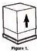
NOTE: Refrigeration equipment must remain upright to avoid damage to the compressor In order to prevent the oil contained in the compressor from flowing into the cooling circuit, it is necessary to always ship, carry, store and handle this Granita machine in an upright position, following the instructions located on the packaging. Never ship, carry, store or handle unit on its side.
Installation
1.) Cut banding straps from box and lift the box off the machine (see fig. 1).
2.) Positioning the machine
The machine must be well ventilated. Leave an 8" (20 cm) clearance on the sides and back of the machine to allow proper ventilation. Installation of the machine near a heat source should be avoided. Some heat sources you should avoid locating this unit too close to are ovens, coffee machines, cold or frozen beverage dispensers or ice machines (equipment with compressors that expel hot air through its vents. An ambient temperature between 59°F (15°C) and 77°F (25°C) is recommended.
Connection to Main Power Supply
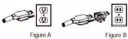
- The electrical safety of this Granita machine can only be achieved if the machine is properly connected to an appropriate grounded receptacle that is in compliance with current national safety standards. Therefore, the manufacturer cannot be held responsible for damage and/or injury caused by failure to connect the unit to an appropriate power source.
- For a safe and correct installation, connect the unit to a dedicated outlet.
- Do not alter the cord or plug in any way.
- The entire length of the power supply cord must not, in any way, be compressed (bent or bunched together) nor may extension cords be used.
- Do not obstruct the ventilation and heat dispersion grill vents on the side and rear panels of the unit. An insufficient ventilation process may reduce the efficiency of the machine, causing it to function inadequately, and cause serious damage to the machine. A minimum of eight inches (20cm) clearance is necessary on each side and behind the unit.
WARNING: THIS UNIT MUST BE PROPERLY ELECTRICALLY GROUNDED TO AVOID POSSIBLE FATAL ELECTRICAL SHOCK OR SERIOUS INJURY TO THE OPERATOR. THE POWER CORD IS PROVIDED WITH A THREE PRONG GROUNDED PLUG. IF A THREE-HOLE GROUNDED ELECTRICAL OUTLET IS NOT AVAILABLE, USE AN APPROVED METHOD TO GROUND THE UNIT. DO NOT USE EXTENSION CORDS WITH THIS UNIT. DO NOT "GANG" TOGETHER WITH OTHER ELECTRICAL DEVICES ON THE SAME OUTLET.
Operating Procedure
Left - Right Middle Bowl Switches:
Each switch corresponds to the number and location of the bowls configuration to the dispenser. When the switch is in the up/on position the motor and cooling will be turned on.

Care and Cleaning
Preparing Product
Attention: Make sure that the mixture has a 13% - 15% minimum Brix (sugar content). A lower concentrate could seriously damage the mixing parts, as well as the gear motors. NEVER USE ONLY WATER.
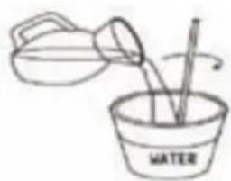
- If using product concentrate (instead of ready-to-use product), dilute and mix the product with water, according to the directions given by the manufacturer, in a separate container. Never pour dry powder, crystals, or concentrate into a dry bowl.
- Remove the merchandising lid. Pour the prepared product into the bowl. Do not spill any material on lid or on bowl. There is a minimum and maximum fill line on the bowl. Do not overfill or run the unit without enough product. Running unit with product below the minimum full line may cause damage to the unit. Insert the plug into a dedicated electrical outlet.
natural_image
Simple line drawing of a water being poured into a bowl with stirring (no text or symbols)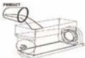
natural_image
Technical line drawing of a mechanical device with cylindrical components and housing (no text or symbols)Dispensing
Product
To dispense the product, position the cup under the dispensing valve and lower the dispensing lever.
natural_image
Line drawing of a portable electronic device with a bulb and speaker (no text or symbols)NOTE: If the machine is turned off at night, with the bowls filled, or just partially filled, a layer of solid ice may form on the surface due to the natural separation of the unmixed (non-moving) product. In this case, before turning the machine back on, remove the layer of superficial ice to prevent damage to the spiral agitator.
Adjustments
Consistency Adjustment:
- Unplug the machine.
-
Be sure that product in the bowl is within proper fill range.
(Above the minimum fill line) Remove merchandiser. -
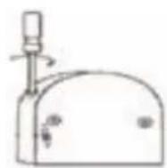
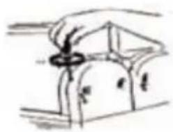
Change the thickness of the product by turning the screw on the back of the bowl, as shown on fig. Turn the screw clockwise for thinner product or counterclockwise for thicker product, (+) thicker, (-) thinner. Each bowl has its own adjusting screw.
natural_image
Simple line drawing of a hand holding a circular object over a curved surface (no text or symbols)Cleaning Procedures
Disconnect the unit from the power supply before sanitizing and cleaning. Failure to do so may result in electric shock.
Daily Cleaning: For the machine to function properly, it is important that the cleaning procedures be carried out daily, according to the following instructions:
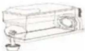
Turn off the equipment and empty the bowl of its remaining product. After draining the product from the unit, you can fill the bowl with hot water (not boiling) to help melt off any sugar deposits. Drain the water prior to proceeding to the next step. To disassemble the draw valve, extract the pin from its seat and the rest of the parts will come out. Wash them with care in warm water.
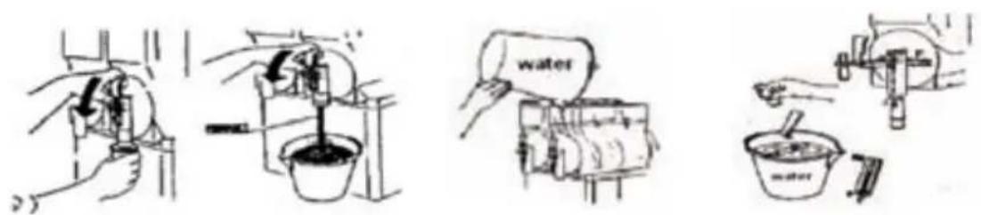
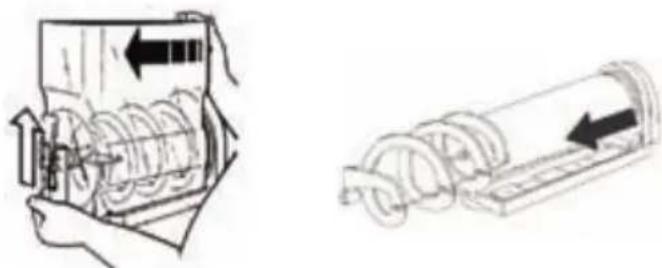
Remove the bowl by lifting the front part until released, then gently hit on the rear side to completely remove it. Take off the bowl, the spiral agitator and the rear gasket.
natural_image
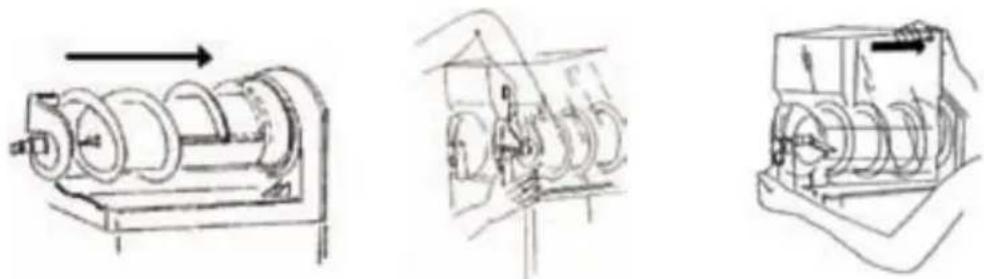
Technical illustration of a mechanical device with internal components and directional arrows (no text or symbols)Before replacing the spiral agitator put gaskets in their seats and lubricate them with the supplied food grade lubricant. Insert the spiral agitator and place back the bowl in its seat. Lightly lift the front part of the spiral agitator until it corresponds to point D. The bowl and the spiral will join. Push the bowl down until you hear a click and replace the tap.
natural_image
Technical line drawings of three mechanical components: a cylindrical motor, a gear mechanism, and a box-like device (no text or symbols present)Do not put in dishwasher. Dishwasher may damage some parts such as the clear plastic auger gears and top mixing bar. Reassemble with clean hands.
Maintenance
Warning: Disconnect the unit from its power supply prior to performing any maintenance procedures. Failure to do so could result in electric shock, injury from hazardous moving parts or serious burns from hot surfaces.
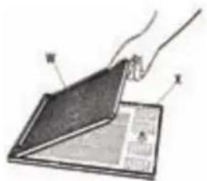
Removing and cleaning the filter (Weekly)
natural_image
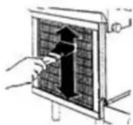
Hand inserting a black arrow into a grid-patterned panel (no text or symbols visible)Cleaning the Condenser (Monthly)
Failure to maintain a clean filter and condenser will cause damage to the unit not covered by warranty.
EXPLODED VIEW & PARTS LIST
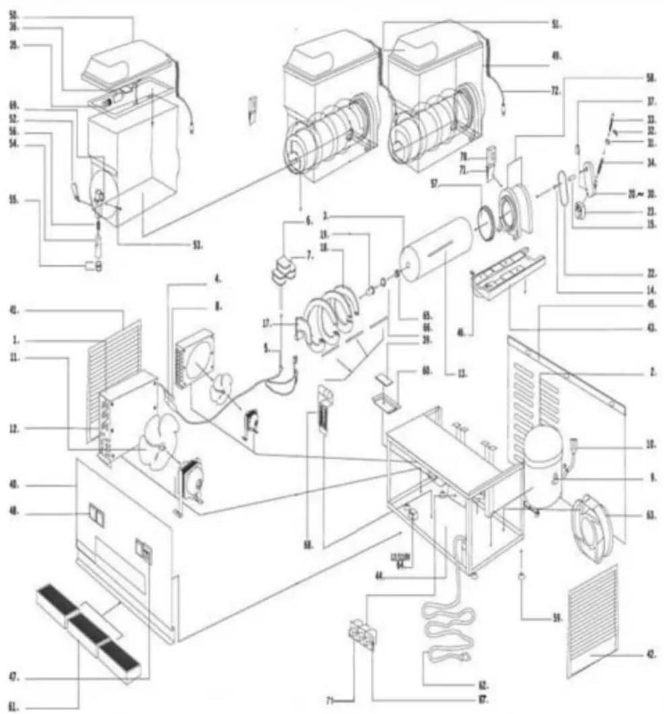
Parts List
Serial No. Part No. Description
1 PSH-GL1000-4 Condenser
2 PSH-GL1002-5 Compressor-OFS20
PSH-GL1002-4 Compressor-OFS30
3 PSH-GL1005 Evaporator
4 PSH-GL1006 Filter Dryer
5 PSH-GL1007 Gas Valve
6 PSH-GL1009-UL Coil for Gas Valve 110V (UL)
7 PSH-GL1009 Coil for Gas Valve 220V
8 PSH-GL1012 High Air Pressure Valve
9 PSH-GL1013 Low Air Pressure Valve
10 PSH-GL1015-1 Fitting-OFS20
PSH-GL1015-2 Fitting-OFS20
PSH-GL1015-3 Fitting-OFS30
PSH-GL1515-4 Fitting-OFS30
11 PSH-GL1016-1-UL Fan Motor 110V (UL)
12 PSH-GL1017 Fan Blades
13 PSH-GL2000 Drive Spindle for Spiral
14 PSH-GL2001 C Ferrule
15 PSH-GL2002 Bushing
16 PSH-GL2003 Drive Spindle for Spiral
17 PSH-GL2004 Scraper for Spiral
18 PSH-GL2005 Spiral Section
19 PSH-GL2006 Clip for Attaching Scraper
20 PSH-GL2007 Gear Box
21 PSH-GL2008 Box Cap
22 PSH-GL2009 Seal
23 PSH-GL2010-1 Stirring Motor + Coil
24 PSH-GL2011-1 Coil
31 PSH-GL2028 Bushing for Hardness Control Pin
32 PSH-GL2029 Hardness Control Catch
33 PSH-GL2030 Hardness Control Screw
34 PSH-GL3000 Twisted Spring
35 PSH-GL3001 Light Bulb Assembly
39 PSH-GL3005 PC-Board
40 PSH-GL4000-2-UL Front Metal Panel OFS20
PSH-GL4000-3-UL Front Metal Panel OFS30
41 PSH-GL4001-1-BLK Side Panel-Left (Black)
42 PSH-GL4003-BLK Side Panel-Right (Black)
43 PSH-GL4004-2-UL Back Metal Panel OFS20
PSH-GL4004-3-UL Back Metal Panel OFS30
44 PSH-GL4005-2 Frame OFS20
Serial No. Part No. Description
PSH-GL4005-3 Frame OFS30
45 PSH-GL4006-BLK Plastic Holder (Black)
46 PSH-GL4007 Pin
47 PSH-GL4008 Power Switch
48 PSH-GL4009 Motor Select Switch
49 PSH-GL4010 PC Bowl
50 PSH-GL4011 PC Bowl Cap
51 PSH-GL4012 Artwork Plate
52 PSH-GL4013 Handle (Tap)
53 PSH-GL4014 Pin (Tap)
54 PSH-GL4015 Piston
55 PSH-GL4016 O-Ring
56 PSH-GL4017 Spring
57 PSH-GL4018 Seal (Bowl)
58 PSH-GL4019 Fixed Evaporator Set & Cap
PSH-GL5036 Fixed Evaporator Cover
59 PSH-GL4021-2-UL Support Feet UL
60 PSH-GL4022 Cover for PC Board
61 PSH-GL4023-BLK Drip Tray (Black)
62 PSH-GL4028-UL Power Cord UL
63 PSH-GL1018-1 Subsidiary Fan Motor UL
64 PSH-GL3006-1-UL Transformer UL
65 PSH-GL3007 Gasket
66 PSH-GL3008 Bushing
67 PSH-GL3009-3 Protective Switch 20A OFS20
PSH-GL3009-4 Protective Switch 30A OFS30
68 PSH-GL3010 Terminals Connectors Set
69 PSH-GL4029 Positioning Ring
70 PSH-GL5006 Power Box
71 PSH-GL5007 Bracket
72 PSH-GL5034-UL Power Cord UL
Electric Circuit Diagram OFS30
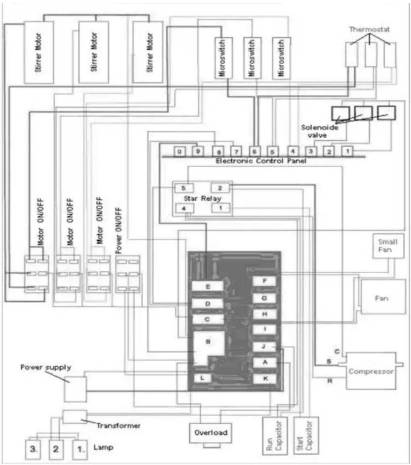
flowchart
graph TD
    A["Stirrer Motor"] --> B["Motor ON/OFF"]
    C["Stirrer Motor"] --> D["Motor ON/OFF"]
    E["Stirrer Motor"] --> F["Power ON/OFF"]
    G["Microswitch"] --> H["Electronic Control Panel"]
    I["Microswitch"] --> H
    J["Microswitch"] --> H
    K["Solenolde valve"] --> H
    L["Star Relay"] --> H
    M["Power supply"] --> N["Transformer"]
    O["Lamp"] --> P["3."]
    O --> Q["2"]
    O --> R["1."]
    S["Overload"] --> T["Run Capacitor"]
    U["Start Capacitor"] --> V["Compressor"]
    W["Small Fan"] --> X["Fan"]
    Y["Thermostat"] --> Z["Solenolde valve"]
    style A fill:#f9f,stroke:#333
    style C fill:#f9f,stroke:#333
    style E fill:#f9f,stroke:#333
    style G fill:#f9f,stroke:#333
    style I fill:#f9f,stroke:#333
    style J fill:#f9f,stroke:#333
    style K fill:#f9f,stroke:#333
    style L fill:#f9f,stroke:#333
    style M fill:#f9f,stroke:#333
    style N fill:#f9f,stroke:#333
    style O fill:#f9f,stroke:#333
    style P fill:#f9f,stroke:#333
    style Q fill:#f9f,stroke:#333
    style R fill:#f9f,stroke:#333
    style S fill:#f9f,stroke:#333
    style T fill:#f9f,stroke:#333
    style U fill:#f9f,stroke:#333
    style V fill:#f9f,stroke:#333
    style W fill:#f9f,stroke:#333
Limited Warranty:
One (1) Year Parts and Labor
OMEGA and Asbury Service Warranty & Parts (ASW&P) warrants to the original purchaser of the OMEGA Granita Dispenser and all parts thereof to be free from defects in material and workmanship while under normal use and service as indicated by the OMEGA installation and operating instructions for a period of one (1) year from the date of installation (warranty registration must be filed within 10 days of installation for warranty to be activated). OMEGA's obligation under this warranty shall be limited to repairing or replacing, including parts and labor, Monday thru Friday from 8:00a.m. to 5:00p.m. excluding holidays and weekends and reasonable travel not to exceed two (2) hours or one hundred (100) miles round trip, any part or assembly of such product which proves to be defective and which upon examination by an ASW&P authorized service technician shall disclose to our satisfaction to be defective. Neither Omega nor Asbury Service Warranty & Parts shall be held responsible for spoilage of products, loss of sales or consequential damages. Any after hours, premium or emergency service must have ASW&P's authorization prior to having service dispatched or a claim filed for warranty consideration. Other conditions and limitations may apply and can be found on the back of the warranty registration card (supplied separately).
natural_image
Black-and-white photo of two Omega Commercial water pumps with transparent glass cases and mechanical components (no visible text or symbols on the pump bodies)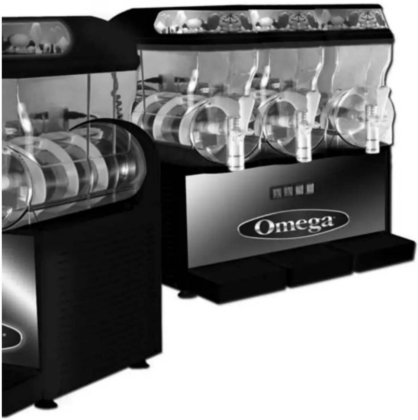
natural_image
Black and white photo of a Omega-branded coffee maker with transparent glass panels and circular cavities (no visible text or symbols on main subject)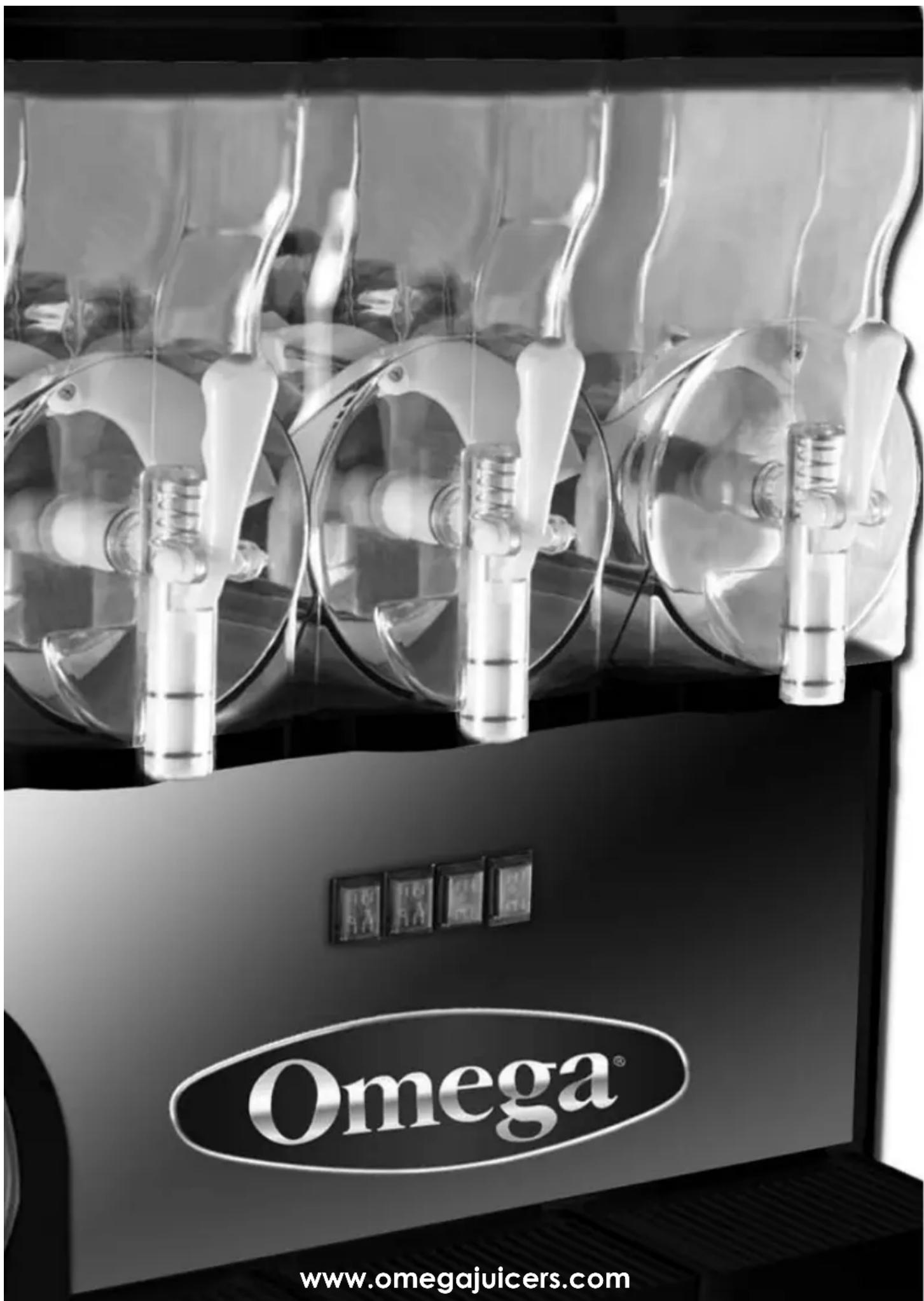
The Legacy Companies, Weston, FL 33331 U.S.A.
- OFS20 & OFS30 GRANITA MACHINE
- TABLE OF CONTENTS
- Specifications 3
- OFS20
- OFS30
- OFS20 Power Requirements:
- OFS30 Power Requirements:
- Instructions for Machine Transport
- Installation
- Connection to Main Power Supply
- Operating Procedure
- Care and Cleaning
- Preparing Product
- Dispensing
- Product
- Adjustments
- Cleaning Procedures
- Disconnect the unit from the power supply before sanitizing and cleaning. Failure to do so may result in electric shock.
- Maintenance
- EXPLODED VIEW & PARTS LIST
- Parts List
- Serial No. Part No. Description
- Limited Warranty:
Brand : OMEGA
Model : OFS20
Category : Water dispenser