
AID864DD - Cooker Artusi - Free user manual and instructions
Find the device manual for free AID864DD Artusi in PDF.


| Product Type | Freestanding Cooker |
| Brand | Artusi |
| Model | AID864DD |
| Dimensions (H x W x D) | 900 x 600 x 600 mm |
| Weight | Approx. 55 kg |
| Power Supply | 220-240 V, 50/60 Hz |
| Hob Type | Gas (4 burners) with electric grill |
| Oven Type | Electric fan-assisted oven |
| Oven Capacity | 70 L |
| Oven Functions | Convection, grill, defrost, pizza, etc. |
| Energy Class | A+ |
| Cleaning Method | Enamel interior, easy-clean |
| Safety Features | Flame failure device, child lock, overheat protection |
| Spare Parts Availability | Compatible with standard Artusi parts |
| Repairability Index | 8 / 10 |
| Installation Type | Freestanding, requires gas/electric connection |
Frequently Asked Questions - AID864DD Artusi
User questions about AID864DD Artusi
0 question about this device. Answer the ones you know or ask your own.
Ask a new question about this device
Download the instructions for your Cooker in PDF format for free! Find your manual AID864DD - Artusi and take your electronic device back in hand. On this page are published all the documents necessary for the use of your device. AID864DD by Artusi.
USER MANUAL AID864DD Artusi
Congratulations, you are now the proud owner of an ARTUSI cooking appliance. Thank you for purchasing ARTUSI and welcome to the ARTUSI Family.
This instruction manual has been specially created to inform you of the full range of features your ARTUSI appliance has to offer and serves as an introduction to getting the very best out of your ARTUSI appliance.
We present detailed information on each of the features your ARTUSI appliance consists of. Once you have read this section you will be able to choose the most appropriate settings for your appliance when cooking different types of food.
We ask you to read the instructions in this booklet very carefully as this will allow you to get the best results from using your appliance. KEEP THE DOCUMENTATION OF THIS PRODUCT FOR FUTURE REFERENCE.
TO REGISTER YOUR PRODUCT WITH ARTUSI, PLEASE FILL OUT THE WARRANTY CARD AT THE END OF THIS BOOKLET AND POST IT TO: REPLY PAID 83617
LEICHHARDT NSW 2040
Dear Artusi Customer, please read this user manual carefully before using the product and, keep it permanently at your disposal.
Note: This user manual is prepared for more than one model. Some of the features specified in this Manual may not be available on your appliance.
All our appliances are only for domestic use, not for commercial use. Products marked with (*) are optional.
"THIS APPLIANCE SHALL BE INSTALLED IN ACCORDANCE WITH THE REGULA TIONS FORCE AND ONLY USED IN A WELL VENTILATED SPACE. READ THE INSTRUCTIONS BEFORE INSTALLING OR USING THIS APPLIANCE"
"Conforms with the WEEE Regulations."
Safety Warnings INDD94 & AID864DD
- The appliance is not intended for use by persons (including children) with reduced physical, sensory or mental capabilities, or lack of experience and knowledge, unless they have been given supervised or instruction concerning use of the appliance by a responsible person for their safely.
- Young children should be supervised to ensure that they do not play with the appliance.
- If the supply cord is damaged, it must be replaced by the manufacturer or its service agent or a similarly qualified person in order to avoid a hazard.
- Do not use a steam cleaner to clean this appliance
- Metallic objects such as knives, forks, spoons and lids should not be placed on the hotplate since they can get hot
- WARNING: If the surface is cracked, switch off the appliance to avoid the possibility of an electric shock
- This appliance is not intended to be operated by means of external timer or separate remote control system
- If the electrical supply is restricted, means of all-pole disconnection must be accessible and incorporated in the fixed wiring in accordance with the wiring rules.
- Danger of fire – Do not store items on the cooking surface
- CAUTION – The cooking process has to be supervised. A short term cooking process has to be supervised continuously.
- Warning – Unattended cooking on a hob with fat or oil can be dangerous and may result in a fire
- Range Hoods and other cooking fume extractors may adversely affect the safe operation of appliances burning gas or other fuels (including those in other rooms) due to lack of back flow of combustible gases. These gases can potentially result in carbon monoxide poisoning. After installation of a range hood or other cooking fume extractor, the operation of flued gas appliances should be tested by a competent person to ensure that back flow of combustion gases do not occur
-
There is a risk of fire if cleaning is not carried out in accordance with the instructions.
-
Caution: Accessible parts may become hot when used with a cooking appliance.
- Do not flambé under the range hood.
For Installation Instructions:
- The exhaust air must not be discharged into a flue which is used for exhausting fumes from other appliances burning gas or other fuels. (Not applicable for appliances which only discharge air back into the room)
• Regulations concerning the discharge of air have to be fulfilled. - Warning: Failure to install the screws or fixing devices in accordance with the instructions may result in an electrical hazard.
Note 1: The instructions must include details concerning cleaning instructions and frequency of cleaning
Note 2: If the Instruction Manual for installation show any screws that are intended to penetrate the range hood enclosure during installation or for any accessory attachments such as flue attachments, then associated screws marked in the manual must be marked with the size of the intended screw used for use. Usually these screws are provided with the appliance but the manual must indicate the screw size intended to be used for these applications.
Chapters
GENERAL....4
II WARNINGS....6
III INSTALLATION 9
III.1 PRELIMINARY INDICATIONS....9
III.2 INSTALLATION 11
III.2.a INDUCTION HOB INSTALLATION 14
III.2.b ASPIRATION INSTALLATION 17
III.3 ELECTRICAL CONNECTION 21
IV OPERATION....24
IV.1 DESCRIPTION OF THE INDUCTION HOB 24
IV.1.a TECHNICAL CHARACTERISTICS 24
IV.1.b BASIC CONTROL CHARACTERISTICS 24
IV.2 USE OF THE INDUCTION HOB.... 25
IV.2.a AUTO-LOCK 25
IV.2.b SWITCH ON/OFF THE COOKTOP 25
IV.2.c SWITCH ON A HEATER ZONE 26
IV.2.d SWITCH OFF A HEATER ZONE 27
IV.2.e SELECTION OF HEATER'S TIMER /WARM FUNCTION 27
IV.2.f INCREASE / DECREASE POWER LEVEL WITH SLIDER 27
IV.2.g BOOSTER FUNCTION 28
IV.2.h BRIDGE FUNCTION 28
IV.2.i HEAT-UP FUNCTION 29
IV.2.1 SECURITY 30
IV.2.m SOFTWARE VERSION VISUALIZATION 30
IV.2.n TIMER 31
IV.2.o AUTOMATIC SAFETY OFF 33
IV.2.p RESIDUAL HEAT INDICATION.... 33
IV.2.q POT DETECTION 33
IV.2.r DISPLAYING SPECIAL STATUSES IN TOUCH CONTROL 34
IV.3 COOKIG ADVICES 34
IV.3.a PAN QUALITY 34
IV.3.b PAN DIMENSION 35
V CLEANING AND MAINTENANCE....40
V.1 INDUCTION HOB CLEANING 40
V.2 COOKER HOOD CLEANING 40
VI WHAT TO DO IN CASE OF A PROBLEM....41
VI.1 ERRORS / ALARMS 42
VII DISCONTINUATION, DISASSEMBLY AND WASTE DISPOSAL....42
VII.1 DISCONTINUATION 42
VII.2 DISASSEMBLY 43
VII.3 ENVIRONMENT PRESERVATION.... 43
VII.4 WASTE DISPOSAL 43
GENERAL
This guide describes the appliance and its use. This guide is an integral part of the appliance itself and has to be retained with the appliance and ALWAYS accompany it, even in case of its assignment to another owner or user or in case the cooker hood is moved to another installation plant.
The aspiration system is composed by three appliances:
■ Two induction hobs;
■ An integrated cooker hood.
The appliances are electrically and functionally independent.
II WARNINGS
CAUTION: This appliance has not been designed for gas hobs.
• This appliance is manufactured according to the safety standards in force.
- The use of this appliance must not be other than the one it has been designed for; this means as an induction hob for cooking in domestic kitchens with an integrated aspiration for cooking fumes;
- The manufacturer does not accept any liability for damages caused by people, animals or things, by installation and maintenance mistakes or by any illegitimate use.
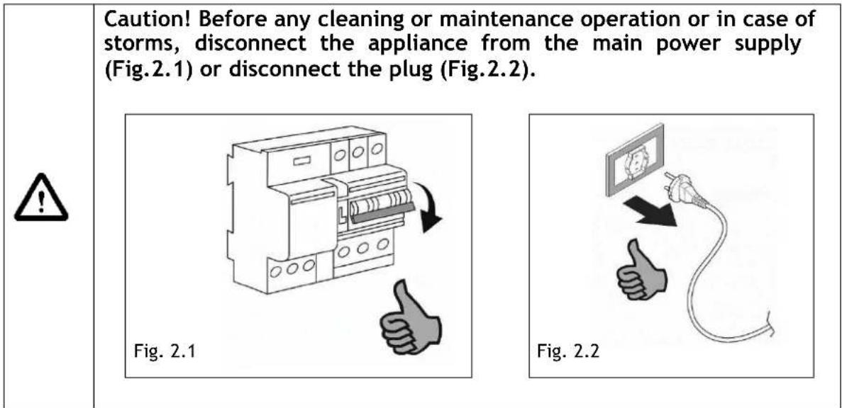
- While the induction hob is active, even the aspiration parts adjacent to the induction hob may become hot.
- There is a possibility of fire if the cleaning operations are not carried out as indicated in the instructions.
- Don't use high-pressure steam cleaner or hot steam to clean the appliance;
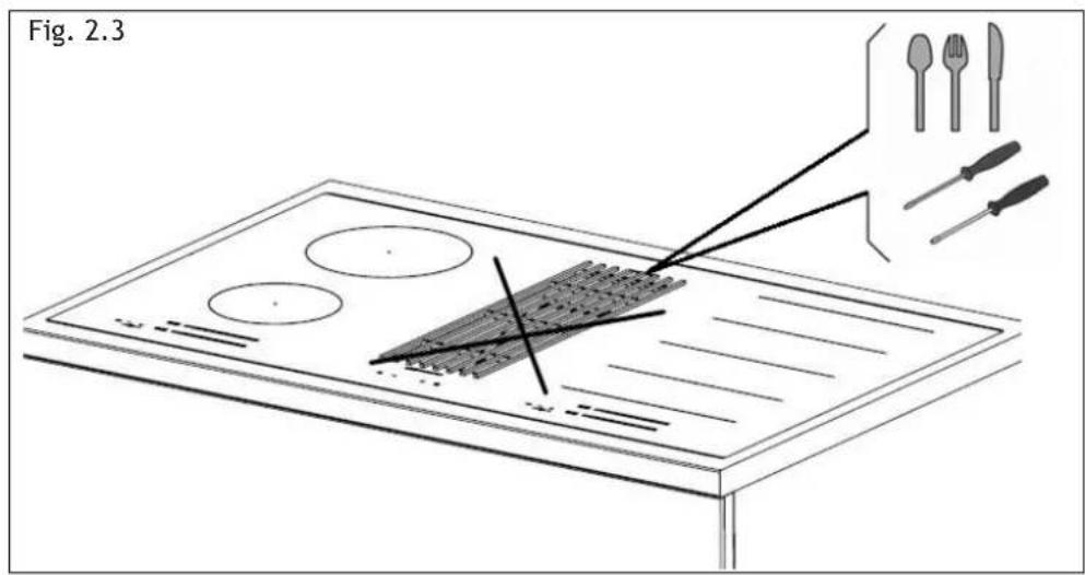
- It is forbidden to introduce any object through the central grille (fig.2.3).
- Do not use the appliance for room heating;
- If there is a wall power outlet located near the appliance and another appliance is plugged into it, make sure the power cord does not come into contact with the hot cooking zones;
- It is forbidden to pull, disconnect, twist the electrical wiring out of the appliance even if it is disconnected from the power supply;
- Do not flambé.
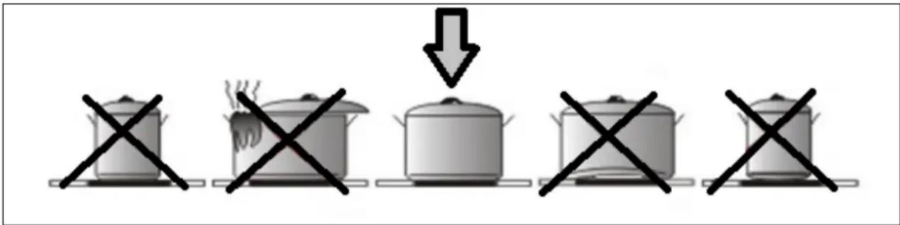
- In order to avoid any undesired disturbance on the touch control, place correct pots inside the marked place of the glass ceramic surface.
Precautions before using
- Unpack all the materials.
- The installation and connecting of the appliance have to be done by approved specialists. The manufacturer cannot be responsible for damage caused by building-in or connecting errors.
- To be used, the appliance must be well-equipped and installed in a kitchen unit and an adapted and approved work surface.
- This domestic appliance is exclusively for the cooking of food, to the exclusion of any other domestic, commercial or industrial use.
- Remove all labels and self-adhesives from the ceramic glass.
- Do not change or alter the appliance.
- The cooking plate cannot be used as freestanding or as working surface.
- The appliance must be grounded and connected conforming to local standards.
- Do not use any extension cable to connect it.
- The appliance cannot be used above a dishwasher or a tumble-dryer: steam may damage the electronic appliances.
- The appliance is not intended to be operated by means of external timer or separate remote-control system.
Using the appliance
- Switch the heating zones off after using.
- Keep an eye on the cooking using grease or oils: that may quickly ignite.
- Be careful not to burn yourself while or after using the appliance.
- Make sure no cable of any fixed or moving appliance contacts with the glass or the hot saucepan.
- Magnetically objects (credit cards, floppy disks, calculators) should not be placed near to the engaged appliance.
-
Metallic objects such as knives, forks, spoons and lids should not be placed on the hob surface since they can get hot.
-
In general, do not place any metallic object except heating containers on the glass surface. In case of untimely engaging or residual heat, this one may heat, melt or even burn.
- Never cover the appliance with a cloth or a protection sheet. This is supposed to become very hot and catch fire.
- This appliance can be used by children aged from 8 years and above and persons with reduced physical, sensory or mental capabilities or lack of experience and knowledge if they have been given supervision or instruction concerning use of the appliance in a safe way and understand the hazards involved.
• Children shall not play with the appliance.
• Cleaning and user maintenance shall not be made by children without supervision.
Precautions not to damage the appliance
- Raw pan bottoms or damaged saucepans (not enameled cast iron pots,) may damage the ceramic glass.
- Sand or other abrasive materials may damage ceramic glass.
- Avoid dropping objects, even little ones, on the ceramic-glass.
- Do not hit the edges of the glass with saucepans.
- Make sure that the ventilation of the appliance works according to the manufacturer's instructions.
- Do not put or leave empty saucepans on the ceramic-glass hobs.
- Sugar, synthetic materials or aluminum sheets must not contact with the heating zones. These may cause breaks or other alterations of the ceramic-glass glass by cooling: switch on the appliance and take them immediately out of the hot heating zone (be careful: do not burn yourself).
- WARNING: Unattended cooking on a hob with fat or oil can be dangerous and may result in fire.
- CAUTION: The cooking process has to be supervised. A short-term cooking process has to be supervised continuously.
- WARNING: Danger of fire: do not store items on the cooking surface.
- Never place any hot container over the control panel.
- It is necessary to ensure adequate ventilation on the front side of the base so that the air can properly flow.
- If a drawer is situated under the embedded appliance, make sure the space between the content of the drawer and the inferior part of the induction hob is large enough (30 mm). This is essential to guaranty a correct ventilation.
- Never put any inflammable object (ex. sprays) into the drawer situated under the ceramic-glass hob. The eventual cutlery drawers must be resistant to heat.
Precautions in case of appliance failure
- If a defect is noticed, switch off the appliance and turn off the electrical supplying.
- If the ceramic glass is cracked or fissured, you must unplug the appliance and contact the after sales service.
• Repairing has to be done by specialists. Do not open the appliance by yourself. - WARNING: If the surface is cracked, switch off the appliance to avoid the possibility of electric shock.
Other protections
- Note sure that the container pan is always centered on the cooking zone. The bottom of the pan must have to cover as much as possible the cooking zone.
- For the users of pacemaker, the magnetic field could influence its operating. We recommend getting information to the retailer or of the doctor.
- Do not to use aluminum or synthetic material containers: they could melt on still hot cooking zones.
- NEVER try to extinguish a fire with water, but switch off the appliance and then cover flame e.g. with a lid or a fire blanket.
 | THE USE OF EITHER POOR QUALITY POT OR ANY INDUCTION ADAPTOR PLATE FOR NON-MAGNETIC COOKWARE RESULTS IN A WARRANTY BREACH. IN THIS CASE, THE MANUFACTURER CANNOT BE HELD RESPONSIBLE FOR ANY DAMAGE CAUSED TO THE HOB AND/OR ITS ENVIRONMENT. |  |
III INSTALLATION
III.1 PRELIMINARY INDICATIONS
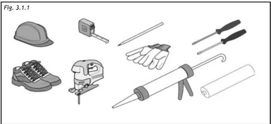
Carefully read the guide before installation and use of the appliances. The installation requires safety equipment and a range of tools as per fig. 3.1.1
natural_image
Illustration of various hand tools including a hard hat, saw, and screwdriver (no text or labels)The aspiration hob is equipped with all the hardware needed for its installation and is suitable for most furniture.
Important: eventually, more screws than necessary for installation have been provided so it is normal to have some left at the end of the installation.
Check minimum dimensions of the base requested for installation (Fig. 3.1.2). Minimum height of the kitchen plinth is very important (min. 100 mm) in order to allow the passage of the air ducts below the base of the furniture. Upon request, it is possible to purchase a special kit for kitchen plinth up to 60 mm height.
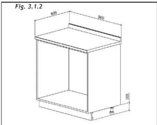
The furniture finishing should be treated with heat resistant glue (100°C) otherwise its shape and colour may change due to the inferior heat resistance.
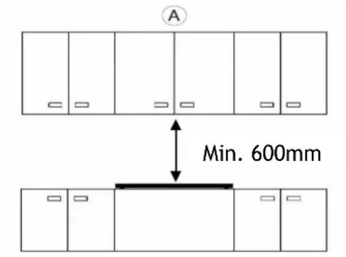
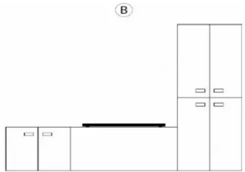
Ideally the appliance should be installed without any adjacent furniture or walls on both sides (Fig.3.1.3-A). Furniture on only one side of the appliance is allowed (Fig.3.1.3-B and Fig.3.1.3-C). To prevent fire hazard, it is strictly forbidden to install any furniture or walls higher than the appliance on both sides (Fig.3.3-D).
Use of wood decoration plates or boards is not permitted.
Fig. 3.1.3
natural_image
Simple line drawing of a cabinet with three doors and a horizontal bar, no text or symbols present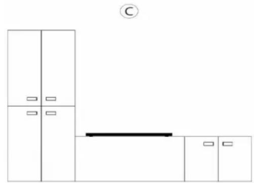
natural_image
Simple line drawing of a cabinet and shelf layout with no text or symbols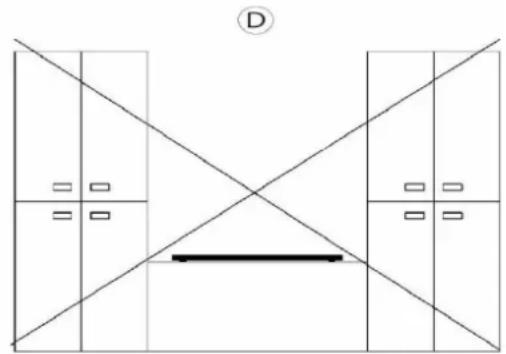
natural_image
Pure architectural floor plan lines without any text, numbers, or symbolsIt is recommended to install the appliance only after having installed the kitchen base cabinet in order to avoid eventual damages to the glass hob.
The safety space between the hob and any furnishings positioned above it must respect a minimum distance of 600 mm. (Fig. 3.1.3-A).
III.2 INSTALLATION
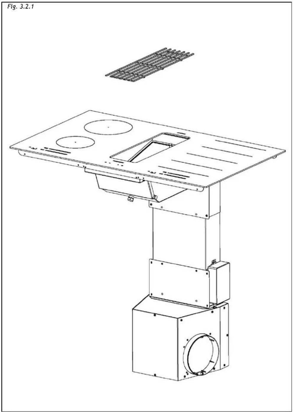
In the box the technician will find the elements shown on Fig. 3.2.1.
Elements must be mounted carefully following the procedure described in this guide.
natural_image
Technical line drawing of a mechanical assembly with mounting base and internal components (no text or symbols)The dimensions of device are shown at Fig. 3.2.2, Fig. 3.2.3
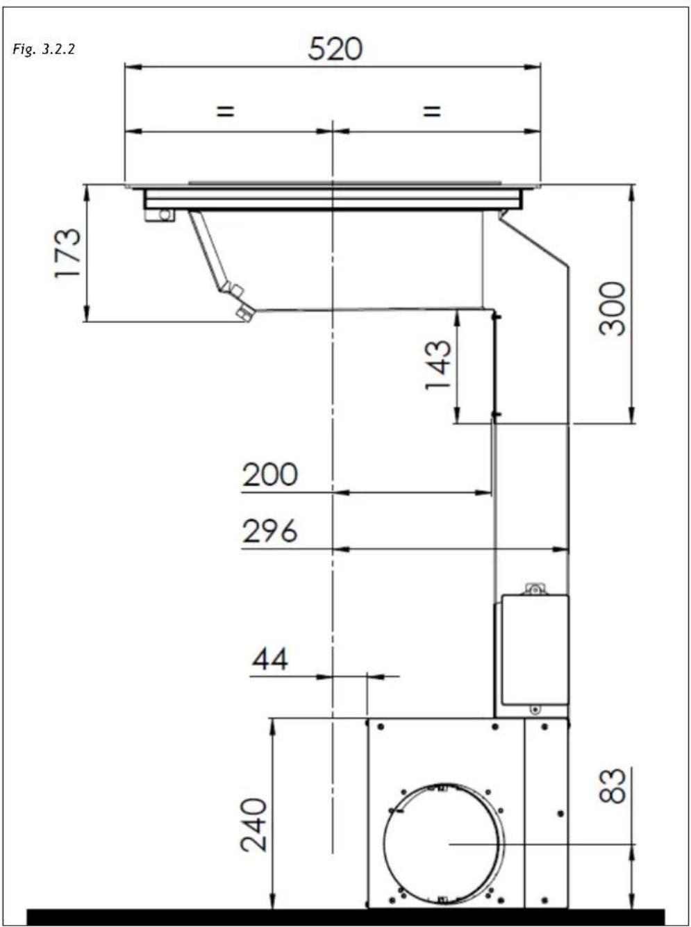
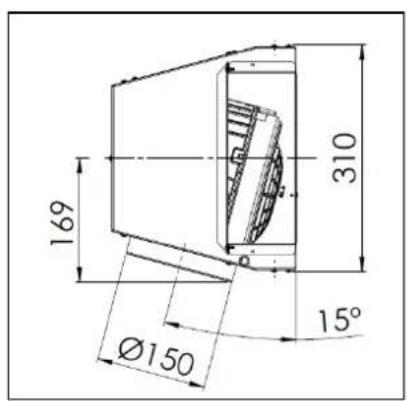
Fig. 3.2.3
This cooker hood can be used as exhausting or filtering.

• Exhausting (external evacuation).
Don't install any activated carbon filters. Kitchen smokes are driven outside through a flue (not provided with the hood) joined to the exhaust pipe flue connector.

Warning! The piping must never be connected to combustion discharge pipes (stoves, boilers, burners, etc.)
The use of pipes and holes on the wall with a smaller section than the output of the motor will cause a decrease in suction performance and an increased of the noise level.
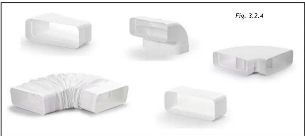
Use as short as possible tubes and with few curves, pipes with smooth internal surfaces are recommended (Fig. 3.2.4)
natural_image
Five white plastic connector components arranged in a fan-like pattern, labeled as Fig. 3.2.4 (no text or symbols on the components themselves)
• Filtering (inside recycling).
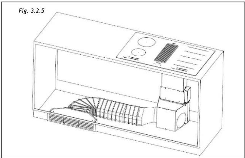
The fumes pass through activated carbon filters to be purified and recycled into the kitchen. The filtering Kit (Fig.3.2.5) is available for the hood in two different high of plinth 6cm and 10cm.
natural_image
Technical line drawing of a microwave oven with fan array and control panel (no text or symbols)III.2.a INDUCTION HOB INSTALLATION
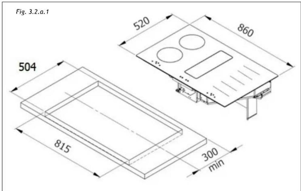
To leave the necessary space for the air pipes it is important to install the induction hob with the centerline more than 300mm away from the wall on the back that may be present.
Installation of the induction hob may be flush or non-flush.
NON-FLUSH INSTALLATION: Prepare the hole in the worktop as shown on Fig. 3.2.a.1.
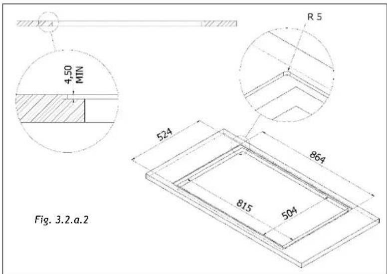
FLUSH INSTALLATION: Prepare the hole in the worktop, mill the worktop along the entire edge of the hole. Be sure to comply with the dimensions indicated on Fig. 3.2.a.2.
The installation comes under the exclusive responsibility of specialists.
The installer is held to respect the legislation and the standards enforce in his home country.
How to stick the gasket:
The gasket supplied with the hob avoids all infiltration of liquids in the cabinet. His installation has to be done carefully, in conformity of the following drawing.
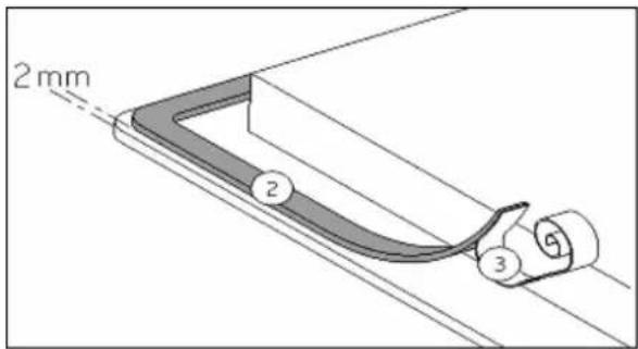
Stick the gasket (2) two millimeters from the external edge of the glass, after removing the protection sheet (3).
Fitting - installing:
- Ensure that there is a distance of 50 mm between the hob and the wall or sides.
- Ideally the hob should be installed with plenty of space on either side. There may be a wall at the rear and tall units or a wall at one side. On the other side, however, no unit or divider must stand higher than the hob.
- The piece of furniture or the support in which the hob is to be fitted, as well as the edges of furniture, the laminate coatings and the glue used to fix them, must be able to resist temperatures of up to 100 °C.
- The mural rods of edge must be heat-resisting.
- Not to install the hob to the top of a not ventilated oven or a dishwasher.
Place the hob on (Fig. 3.2.a.3)
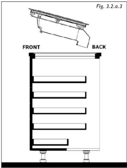
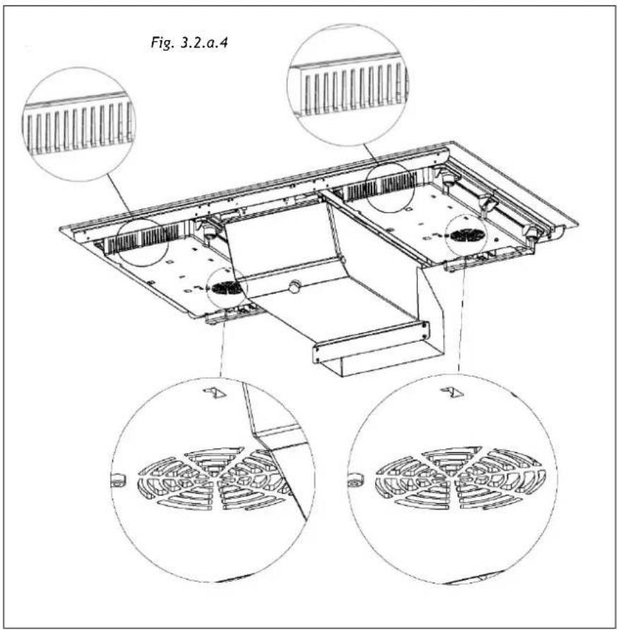
- It is necessary to ensure adequate ventilation on the front side of the base so that the air can properly flow (Fig. 3.2.a.4).
- If a drawer is below the hob, to guarantee a good air circulation and good cooling system of the induction hob, maintain a gap of 30 ~mm minimum between the ventilation of the lower part of the hob and what is stowed inside the drawer (Fig. 3.2.a.4).
- If a drawer is placed under the work, avoid to put into this drawer flammable objects (for example: sprays) or not heat-resistant objects.
- Materials which are often used to make worktops expand on contact with water. To protect the cut-out edge, apply a coat of varnish or special sealant. Particular care must be given to applying the adhesive joint supplied with the hob to prevent any leakage into the supporting furniture. This gasket guaranties a correct seal when used in conjunction with smooth work top surfaces.
• After installation, the connecting cable must not be subjected to any mechanical stress, for example, because of a drawer.
- WARNING: Use only hob guards designed by the manufacturer of the cooking appliance or indicated by the manufacturer of the appliance in the instructions for use as suitable or hob guards incorporated in the appliance. The use of inappropriate guards can cause accidents.
III.2.b ASPIRATION INSTALLATION
The base of the kitchen must be drilled as indicated in Fig. 3.2.b.1 if the space available to house the hood is less than 560mm the back need to be removed.
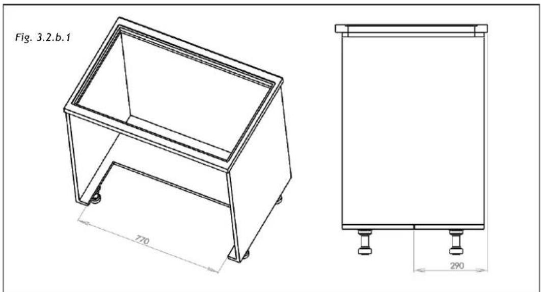
The installation of the appliance implies a maximum length of the drawers that may be mounted under the hob (Fig. 3.2.b.2-A; Fig. 3.2.b.2-B):
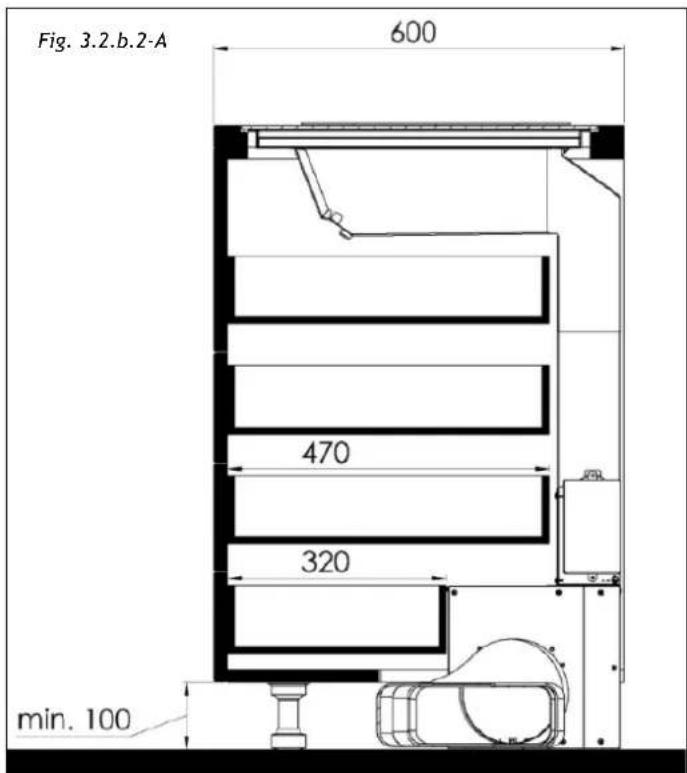

Upper drawers depth approximately 470mm
Last drawer depth approximately 320mm
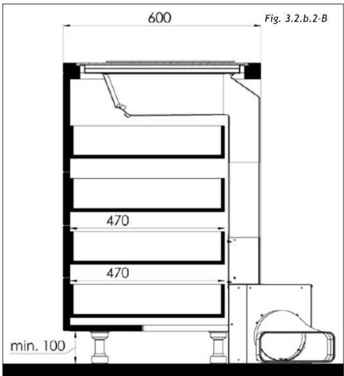

Drawers depth approximately 470mm
The depths of the drawers are approximate and generated by the project of a kitchen base unit with standard dimensions.
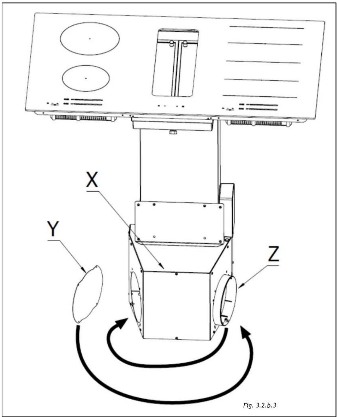
The next step is to determine the exit of the fumes according with the installation needs. The air exit can be on the left or on the right of the kitchen base.
To do this, remove the screws, detach the cover (3.2.b.3 -X) and the cup (3.2.b.3-Y) invert the aspirator outlet (3.2.b.3 -Z) and place the cup on the other side (Fig. 3.2.b.3). Then replace the cover and secure it with the screws (Fig. 3.2.b.3).
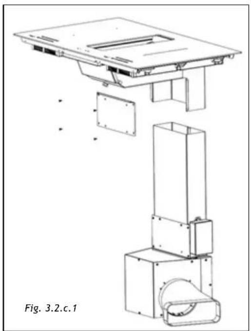
After installing the induction hob as paragraph III.2.a INDUCTION HOB INSTALLATION, align the suction unit with the hob (Fig. 3.2.c.1) by positioning it inside the cut of the base of the piece of furniture previously made (Fig. 3.2.b.1).
natural_image
Technical line drawing of a mechanical assembly with exploded and assembled views (no text or symbols)If the length of the metal pipe is not enough to reach the upper housing it can be increased moving the pipe inside the motor box.
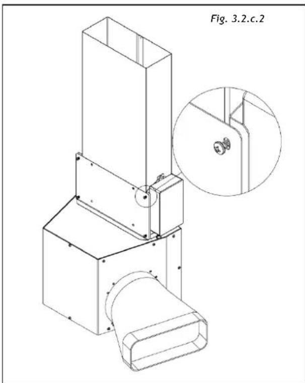
In order to do that it is needed to detach the front panel loosing the four screws without completely remove the panel. (Fig.3.2.c.2)
natural_image
Technical line drawing of a mechanical assembly with a magnified inset showing a circular component detail (no text or symbols)The front panel and the pipe are fixed together with 3 screws (Fig. 3.2.c.3) removing these, the pipe can slide to the upper position and then it can be re-fix with the same screws.
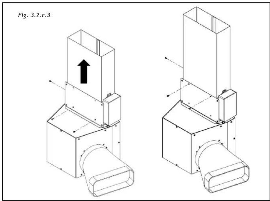
The holes that now are empty can be covered with the cup supplied.
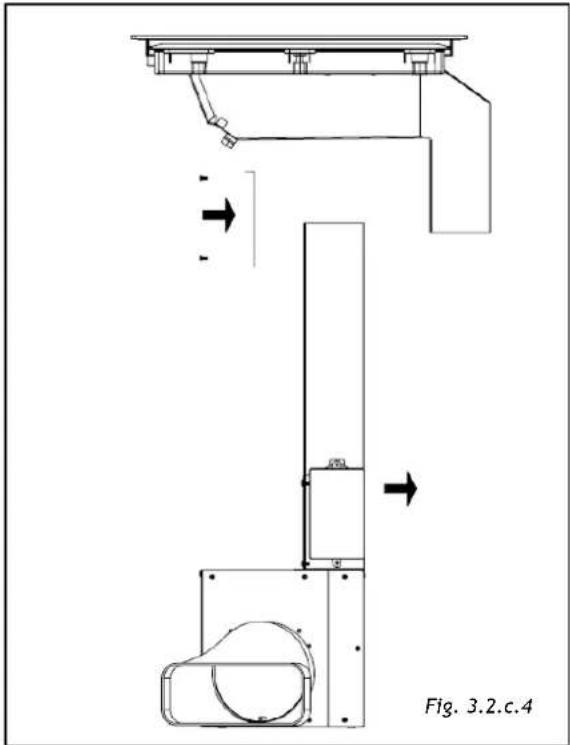
Now the motor box can be inserted in the housing and the panel mounted (Fig. 3.2.c.4)
natural_image
Technical line drawing of a mechanical assembly with no visible text or symbolsTo place the exhaust pipe in the desired position it is necessary to use pipe and connectors to pass under the base of the piece of furniture, inside the lift of the kitchen plinth.
III.3 ELECTRICAL CONNECTION
The electrical connection must be carried out ONLY by qualified technicians.
The electrical protection of the electrical connection upstream of the equipment must comply with the regulations in force.
The appliance is composed by three devices that must be separately connected to the electricity: the serial plate stating the electricity supply needed is located on the suction tray. Make sure that the power supply is enough to supply all the 3 devices.
| Mains | Connection | Cable diameter | Cable | Electrical Protection |
| 220-240V50/60Hz | 1 Phase + N | 3 x 1,5 mm2 | H 05 VV - FH 05 RR - F | 16 A * |
* calculated with the simultaneous factor following the standard EN 60 335-2-6
| Caution! Make sure that the voltage (V) and frequency (Hz) indicated on the serial number plate located on the appliances correspond to those available at the installation site. |
Any change to the electrical installation necessary to install the hood should only be undertaken by qualified staff.
After installation, insulated parts and those carrying electricity must be protected from any possible contact.
 | Caution! If the electrical connection is carried out incorrectly or not meeting the regulations, it may damage part of the appliance and the warranty will not be valid. |
 | Caution! Before any intervention, disconnect the appliance from the power mains (Fig. 2.1 - Fig. 2.2 WARNINGS chapter). |
These appliances must be earthed.
Two types of connections to the network are possible:
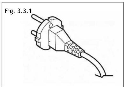
- Using a standard plug connected (Fig. 3.3.1) to the power cord and inserted into an accessible socket outlet (to be disconnected during service operations). Make sure that the plug is accessible even after the complete installation of the appliance.
natural_image
Line drawing of a plug with a cable, labeled Fig. 3.3.1 (no text or symbols on the diagram itself)- Stable connection to the network by interposing a bipolar switch to ensure disconnection from the network, with a contact opening distance allowing complete disconnection under the conditions of the overvoltage category III, in accordance with the installation rules (fig.3.3.2).
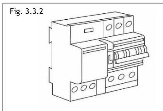
natural_image
Line drawing of an electrical circuit breaker (no text or symbols on the diagram itself)Earth connection (yellow-green wire) should not be interrupted.
If the power cord is damaged, it must be replaced by the manufacturer or its authorized service center or by a qualified technician, in order to prevent any risk.
Caution!
Respect the connection diagram. Use the connecting cable that is attached to the hob. The green / yellow wire corresponds to the earth wire, the blue wire correspond neutral wire and the brown wire correspond to the phase.
Aspirator connection procedure:
First of all, connect the motor box to the induction hob:
- Connect the flat connector (male-female) to the mainboard, with the control's connector dropping from the induction hob (Fig. 3.3.3).
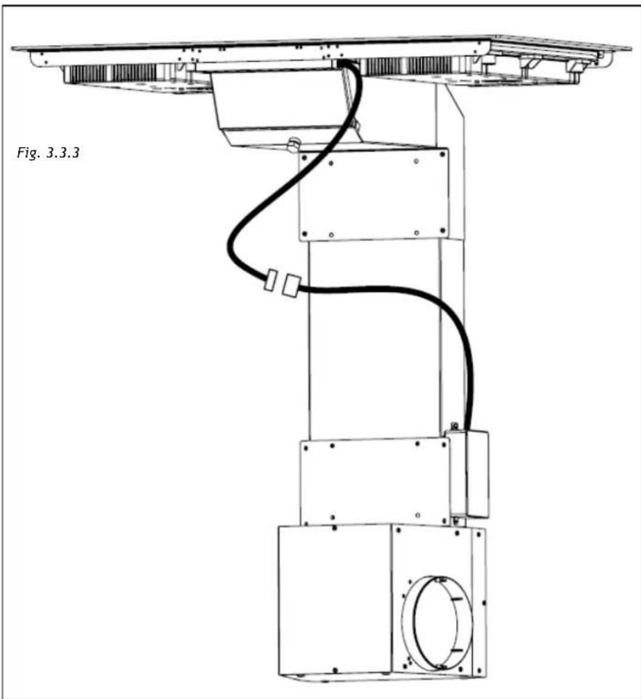
natural_image
Technical line drawing of a mechanical or robotic device with a curved cable and mounting base (no text or symbols)- Protection against the parts under tension must be ensured after the building-in.
- The hob connection to the main must be made using an earthed plug or via an omnipolar circuit breaking device with a contact opening of at least 3 mm.
- The power cord shall be positioned so as not to touch the hot parts of the hob or any other part.
We cannot be held responsible for any incident resulting from incorrect connection or which could arise from the use of an appliance which has not been earthed or has been equipped with a faulty earth connection.
IV OPERATION
IV.1 DESCRIPTION OF THE INDUCTION HOB
IV.1.a TECHNICAL CHARACTERISTICS
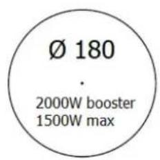
DUAL ZONE 3000W max
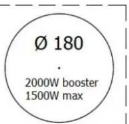
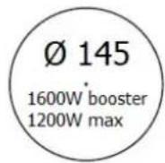
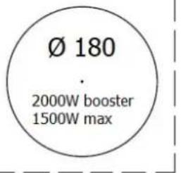
Power level detail:
Power limitation when ∅ 180 heaters are working simultaneously (no bridge function): Total Power 3600W
IV.1.b BASIC CONTROL CHARACTERISTICS
• Auto Lock function
- Fast Boil function
- Bridge function
- Selection of heater's timer / Warm function
- Heat-Up function
- Independent timer for each heater.
- Indication of residual heat for each heater.
• Thermal control protection.
• Protection from accidental activation of keys:
- One or more keys activated for more than 10 sec. -> Switching off the touch control. A warning beep sounds every 10 sec., while the key/s is/are activated.
- With all heaters at zero power during 10 sec. -> The Cooktop is switched off. If the switching off is due to an accidental activation of keys, the touch control actuates as above.
- Acoustic warning to attract the user's attention.
- Pan detection for induction heaters; After 60 sec. with no pan, the heater switches off.
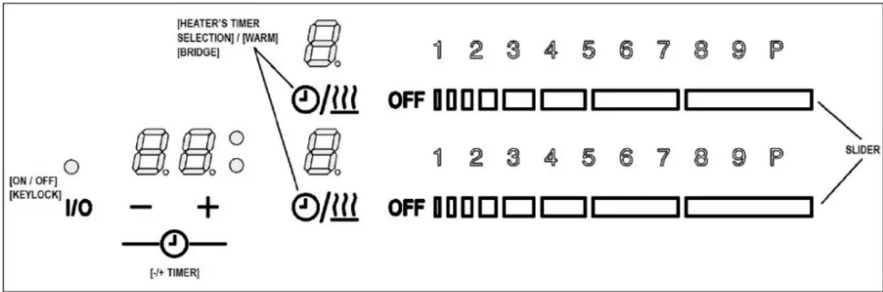
GENERAL KEYS
- 1 key for switching On/Off the Cooktop [ON/OFF] and unlocking the keyboard.
- 2 keys to “time selection”.
HEATER KEYS
- 1 selection key for each heater's timer [Heater_timer_selection] / Warm function
- 1 Slider for each heater to select cook set ((0)-1-2-.....P)
BUZZER SOUNDS
flowchart
graph TD
    A["ON / OFF"] --> B["I/O"]
    B --> C["+"]
    C --> D["/- + TIMER"]
    D --> E["HEATER'S TIMER SELECTION"] / [WARM] --> F["BRIDGE"]
    F --> G["OFF"]
    G --> H["1 2 3 4 5 6 7 8 9 P"]
    G --> I["1 2 3 4 5 6 7 8 9 P"]
    I --> J["SLIDER"]
    J --> K["OFF"]
    K --> L["1 2 3 4 5 6 7 8 9 P"]
![[EATER'S TIMER SELECTION] [WARM] [BRIDOR] 1 2 3 4 5 6 7 8 9 P OFF □□□□□□□□□□□□□□□□□□□□□□□□□□□□□□□□□□□□□□□□□□□□□□□□□□□□□□□□□□□□□□□□□□□□□□□□□□□□□□□□□□□□□□□□□□□□□□□□□□□□□○ [ON/OFF] [NEWLOCK] I/O - + - + - [+ TINER] OFF □□□□□□□□□□□□□□□□□□□□□□□□□□□□□□□□□○ [SIDER] [HEATER'S TIMER SELECTION] [WARM] [BRIDOR] 1 2 3 4 5 6 7 8 9 P OFF □□□□□□□□□□□□□□□□□□□□□□□□□□○ 8.8: ○ - + - [+ TINER] OFF □/√√ OFF □/√√ OFF □/√√ OFF □/√√ OFF □/√√ OFF □/√√ OFF □/√√ OFF □/√√ OFF □/√√ OFF □/√√ OFF □/√√ OFF □/√√ OFF □/√√ OFF □/√√ OFF □/√√ OFF √/√√ OFF □/√√ OFF □/√√ OFF □/√√ OFF □/√√ OFF □/√√ OFF □/√√ OFF □/√√ OFF □/√√ OFF □/√√ OFF □/√√ OFF □/√√ OFF □/√√ OFF □/√√ OFF □/× √ OFF □/× √ OFF □/× √ OFF □/× √ OFF □/× √ OFF □/× √ OFF □/× √ OFF □/× √ OFF □/× √ OFF □/× √ OFF □/× √ OFF □/× √ OFF □/× √ OFF ▢ √ OFF ▢ √ OFF ▢ √ OFF ▢ √ OFF ▢ √ OFF ▢ √ OFF ▢ √ OFF ▢ √ OFF ▢ √ OFF ▢ √ OFF ▢ √ OFF ▢ √ OFF ▢ √ OFF ▢ √ OFF ▢ √](/content/2026/05/1043813/images/62d72933ce9a88a51494730c579a588ab2db07fc6fd0ea94a6870b66908de3f2.jpg)
IV.2 USE OF THE INDUCTION HOB
IV.2.a AUTO-LOCK
When a cooktop is switched off always is locked. So, on all 7-segment of heater1 cooking zone display is shown “Lo” for 5 sec, and then disappear. Each time a key is touched from heater1, 7-segment cooking zone displays is blinked “Lo” to indicate that the hob is blocked. If a key is touched from heater2, nothing happens.

IV.2.b SWITCH ON/OFF THE COOKTOP
The cooktop is switched ON by touching the [ON/OFF] key for 2 second, a double beep sounds and the On/Off status LED is switched on. Heaters display may possibly be change in case of residual heat or error status of the cooking zone.

If the selection of a heater is not done in 10 seconds, the cooktop will be turned off automatically.

The cooktop is switched Off by touching the [ON/OFF] key for 1 sec. A beep sounds and all the heaters are switched Off.


When a cooktop is on (On/Off status LED is on), a heater zone can be switched on pressing a Heater's slider.
In the "Slider's bar graph" is displayed the selected power level.

IV.2.d SWITCH OFF A HEATER ZONE
To switch OFF a heater, the user must to press on the lowest part of the heater's slider, a beep is heard, and heater is OFF. Residual heat indication appears in the display if residual heat exits.


"H" value will appear in target zone digit if residual heat exists.
If only one heater is active and it's switched off, after 10 sg, a short beep will be heard indicating that the cook top is off.
IV.2.e SELECTION OF HEATER'S TIMER /WARM FUNCTION
There are two function in the same key:
- With a short press, the heater's timer is selected, so user can visualize timer time or change timer's value, in case the that the timer is temporized.

- And with a long press the warm function is activated, a "u" power level is showed in the display and slider bar graph is off.

IV.2.f INCREASE / DECREASE POWER LEVEL WITH SLIDER
The power level can be changed with a short press on slider keys, increasing or decreasing the power of the selected zones, and “Slider bar graph” visualizes the selected power than goes from (0)-1-2-3...9- to Booster (P).

IV.2.g BOOSTER FUNCTION
With a short press on the highest level of slider keys, user can select the Booster Functions.
A beep sounds and the heater display shows "P" and the its corresponding slider bar graph visualizes all the bar ON (P level).
The heater will work at maximum power level for 10 minutes. After these 10 minutes a beep sounds and the heater will return to level "9".

IV.2.h BRIDGE FUNCTION
Two heaters can be joined by the bridge function to heat longer pans and griddles.

To enable or disable the bridge function, user must to press a combination of keys (both selection keys of the bridgeable heaters) and a beep sound.


In some case, user will be not be able to activated “Bridge keys combination”, so three shorts beeps are heard. These cases are the following:
If the heaters power level is greater than 0.
If the key lock is activated (KEYLOCK LED on).
To set the power level of the bridge heater press any key of each sliders. Bridge heater power level is shown in bar graphs.

When the heaters are operated as one bridge heater, the selectable power levels are from 1 to 9, it is not possible to select booster power level. When the heaters are operated individually, the selectable power levels are from 1 to P.
When the heaters are operated as bridge heater and want to switch off to zero power level, the user must to press on the lowest part of the heater's slider, a beep is heard, and heater is OFF.
IV.2.i HEAT-UP FUNCTION
User activates the “heat-up” function by pressing for more than 3 second over the slider when cooking zone is working a power level bigger than zero and it has been selected. It is not possible to activate Heat-up function when the heater is working at warm, 9 or P power level.
When Heat-up is activated, the heater operates on the highest power setting (level P) for the duration of the heat-up time. After the heat-up time expired, the cooking zones automatically return to the cooking stage set by the operator previously to the heat-up selection.
The heat-up time is depending on the level of the set cooking stage.
| Cooking level | 0 | 1 | 2 | 3 | 4 | 5 | 6 | 7 | 8 |
| Heat-up time (s) | 0 | 40 | 70 | 120 | 180 | 260 | 430 | 120 | 195 |
The sequence is the following:
➢ Cooking zone must be at level different of 0, Warm, 9 or P on display.
➢ Then press for more than 3 second over the slider when cooking zone is working a power level bigger than zero

The respective cooking zone display shows the symbol "A" for automatic heat-up indication.

If the heat-up boost is realized on a cooking zones with activated pan detection and no pan is detected, an "A" will blink in alteration with the symbol for "no pan".
If a higher cooking stage is selected with the slider, the heat-up function remains active with the new cooking stage.
When a lower cooking stage is selected any time during the automatic heat-up, heat-up function will be deactivated.
If the cooking zone is switched off during active heat-up function, the heat-up is also deactivated.
When the heat-up time has passed as planned, or the automatic heat-up is deactivated by the above-mentioned operating steps, the bargraph shows the set cooking stage. The “A” is deactivated.
IV.2.1 SECURITY
Something (an object or a liquid) is pressing any key during more than 10s. 2 Short Beep + 1 Long beep every 30s while the key is pressed. Cook-top will turn Off. This symbol will maintain blinking while the issue persists.

SW version only can be activated always when cook-top is off and only during the first 30 seconds after power up the cooktop:
-
Unplug and Plug the cooktop, and press the sequence (only during the first 30 seconds after power up the cooktop).
-
First press “- timer”, (Step 1)
-
Without removing “- timer”, ‘then press “+ timer” key simultaneously. (Step2)
-
Without removing the finger of ‘- timer’, touch simultaneously ‘Front heater selection’ key (Step 3).
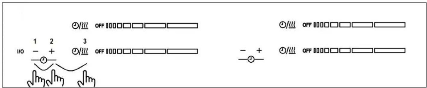
The display sequence is the following:
- First Touch Sw Version is displayed during 10s in timer displays. First, “Functional Software Version” is displayed without any dots and any timer LEDs on. Second, “Safety Software version” is displayed with dots and timer LEDs on.
- Then a short beep is heard and First Induction Generator Sw version is displayed. First, "Functional Software version" is displayed without any dots and any timer LEDs on. Second, Safety Software version" is displayed with dots and timer LEDs on.
- Then another short beep is heard and Second Induction Generator Sw version is displayed. First, “Functional Software version” is displayed without any dots and any timer LEDs on. Second, “Safety Software version” is displayed with dots and timer LEDs on.
- Then another short beep, and the display sequence is finished.
- If a key is pressed during the Sw Display Sequence, the sequence finished and touch control continued at normal operation.
IV.2.n TIMER
The timer function consists in activating different timers that are assigned to individual cooking zones. "00" is displayed in the digits reserved for the timer. When heater timer is elapsed, the heater is switched off.
Timer function is activated when “heater’s timer selection/ /Warm key” is pressed, and the heater’s power level is greater than 0.
Timer LED is blinking indicating that the zone is being timed
With "+Timer" or "-Timer" keys, timer time can be chosen. A Beeps sounds.
➢ Pressing simultaneously timer "+/-" keys the timer is cancelled (goes to 00), but the heater has to be selected.
If timer "+" or "-" keys is maintained pressed during TBD time, there is quick setting timer time.
When setting timer time, it is possible to go from "00" to "99" with "-" key, and from "99" to "00" with "+" key.
▶ Maximum time is 99 minutes.
When the time is elapsed and the hob is beeping, press any key and the alarm and digit sequence will end.
It is possible to adjust the timer time while the timer is previously running, pressing with a short press on the "Heater's timer selection / /Warm key", and user can adjust timer with "+/-" key.
Power of timed zone can be modified without consequences on the timer programming.
Last minute will be displayed in seconds.
- Pressing the "+" or "-" keys without pressing heater's timer selection key, not make nothing.
➢ Remaining time is displayed in the digits reserved for the timer.

If Heater 1 and Heater 2 are timed simultaneously (Touch Control of the left): The smallest remaining time is displayed, and the corresponding timer LED is blinking. The other LED is on continuously.
If Heater 3 and Heater 4 are timed simultaneously (Touch Control of the right): The smallest remaining time is displayed, and the corresponding timer LED is blinking. The other LED is on continuously.

IV.2.o AUTOMATIC SAFETY OFF
If the power level is not changed during a preset time, the corresponding heater turns off automatically. The maximum time a heater can stay on, depends on the selected cooking level.
| Power level | Max. time on (hours) |
| 1 | 10 |
| 5 | 5 |
| 3 | 5 |
| 4 | 4 |
| 5 | 3 |
| 6 | 2 |
| 7 | 2 |
| 8 | 2 |
| 9 | 1 |
IV.2.p RESIDUAL HEAT INDICATION
After a zone has been switched off, an “H” will be displayed depending on the temperature determined by the temperature sensor at cooking zone. The “H” will be displayed statically and will not blink.

When no pot or when un-suitable pot is present after setting a power level, the chosen level and symbol “-u” (small U with bottom line) will blink with rhythm 1 sec and no power is added.
After 30 sec the zone will be switched off automatically. The timeout of 30 sec for pan detection is not affected by pause mode.
In the touch control bar graph indicates the power level indication; there is no special indication of the pot detection.
IV.2.r DISPLAYING SPECIAL STATUSES IN TOUCH CONTROL
The corresponding heater display alternates between two characters depending on the status.
| Special status(Visualization Priority Order) | Start conditions | End conditions | Action | Heater status | Heater Display fore | Heater Display back |
| Power increment not allowed(only for ECO models) | Asked Cooktop power > Cooktop ECO power limit | 2 sec | Power increment not allowed | On/Off ‘r’ | ||
| Heater without suitable pan or without pan | No pan or not suitable pan over the heater | Suitable pan over the heater | After 1 minute Heater off | On ‘Power’ ‘-u’ | ||
| Induction heater overtemperature | COIL TEMPERATURE > T1 (1) | COIL TEMPERATURE < T2 (1) | No power is delivered to the heater | Off ‘‘o‘H’ | ‘C’ | |
| On ‘Power’ | ||||||
| Induction generator overtemperature | HEATSINK TEMPERATURE > T3 (1) | HEATSINK TEMPERATURE < T4 (1) | No power is delivered to the heater | Off ‘‘o‘H’ | ‘c’ | |
| On ‘Power’ | ||||||
| Hot glass over a heater(residual heat) | COIL TEMPERATURE > T5 (1) | COIL TEMPERATURE < T6 (1) | ---- Off | ‘H’ | ||
(1) For T1, T2, T3, T4, T5 and T6 values see the corresponding drawing.
IV.3 COOKIG ADVICES
IV.3.a PAN QUALITY
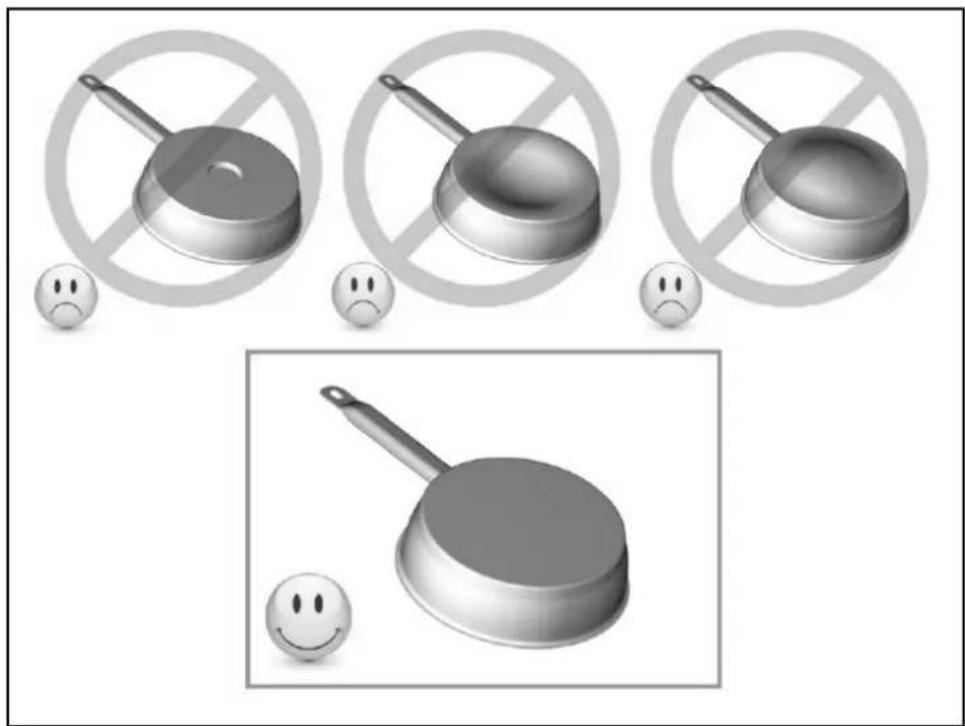
Adapted materials: steel, enameled steel, cast iron, ferromagnetic stainless-steel, aluminum with ferromagnetic bottom.
Not adapted materials: aluminum and stainless-steel without ferromagnetic bottom, cupper, brass, glass, ceramic, porcelain.
The manufacturers specify if their products are compatible induction.
To check if pans are compatibles:
- Put a little water in a pan placed on an induction heating zone set at min. level.
This water must heat in a few seconds.
• A magnet sticks on the bottom of the pan.
Certain pans can make noise when they are placed on an induction cooking zone. This noise doesn't mean any failure on the appliance and doesn't influence the cooking operating.
natural_image
Three grayscale illustrations of frying panes with no text or symbols, accompanied by sad face emojis (no text or symbols present)IV.3.b PAN DIMENSION
However, the bottom of this pan must have a minimum of diameter according to the corresponding cooking zone.
To obtain the best efficiency of your hob, please place the pan well in the center of the cooking Zone.
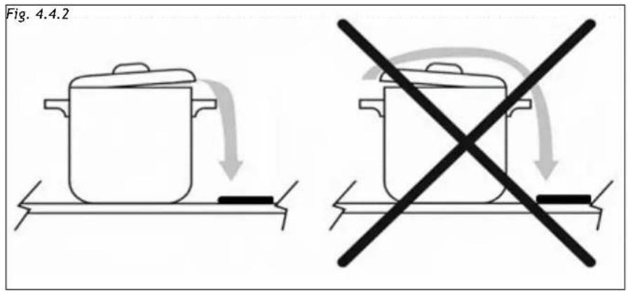
To reach the maximum aspiration try to convert the cooking fumes on the closer side to the aspiration (Fig. 4.4.2).
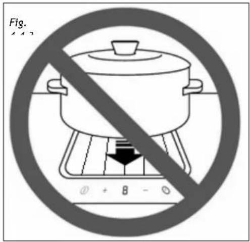
Do not place any object above the aesthetic frame and above the center grille of the hood (Fig. 4.4.3).
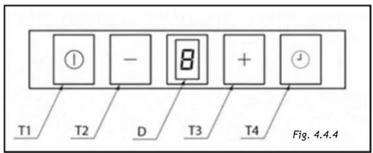
The touch controls are located in front of the aspirator and consist of 4 buttons and a central display (Fig. 4.4.4).
IV.4.a ASPIRATION TURN ON
Touching T1 for 1sec the aspiration turns on at 1st speed.
To increase the speed (2nd - 3rd - 4th or booster) touch T3.
To decrease the speed touch T2 (4th or booster - 3rd - 2nd - 1st).
At the 4th speed (booster) the aspiration will work at the maximum speed for 5 minutes after that it will automatically switch to 3rd speed. The display will blink “4” for the first 5 minutes than “3” constantly.
To turn the hood off touch T1.
Switching off will be possible any speed the aspiration will be working at.
IV.4.c CLEANING FUNCTION
In order to allow the cleaning of the hob the cleaning function is inhibiting the touch controls.
The function is activated by pressing T2 key for 5sec. with the hood turned off.
For a minute, the touch control will be inhibited.
During this period the display will show "C". After one minute the device will normally work
IV.4.d ADJUSTABLE AND DELAYED SELF-SWITCHING OFF
By pressing T4 adjustable and delayed self-switching off of the aspiration can be activated.
The display shows "D":
With the hood in operation, select the desired speed than press T4 to activate the delayed self - switching off.
The display will show “1” blinking followed by a point, where the point stands for programming phase.
By pressing T2 and T3 respectively the self-switching off time could be adjusted from 1 to 4:
1= 5 minutes
2= 10 minutes
3= 15 minutes
4= 20 minutes
Press again T4 to confirm the programming.
During self-switching off operation, you can change the set speed by using the T2 and T3 keys and manually switch off the hood by pressing the T1 key.
You can also change the self-switching off time once set by pressing the T4 key again and resetting the new time: the count will resume from 0.
With the self-switching off activated the display will show cyclically for 5 seconds the set speed with fix light and for the following 5 seconds the self-switching off setting with blinking light.
If you choose the intensive speed, after 5min the hood will go to the 3rd speed and the self-timer will run at the 3rd speed.
With booster set the aspiration will automatically switch to the 3rd speed after 5 minutes, self-switching off will take place at the 3rd speed.
IV.4.e ANTI GREASE FILTER CLEANING ALARM
Every 30 hours' operation, when aspiration is switched off, letter "G" will light up on the display for 30 seconds warning that anti grease filter cleaning is necessary.
To reset the timer press T3 for 5 seconds while aspiration is switched off, otherwise the device will give the same warning the next time aspiration is switched off.
IV.4.f CHARCOAL FILTERS REPLACING ALARM
Every 120 hours' operation, when the hood is switched off, the display will show "S" for 30 seconds reminding the washing or substitution of the charcoal filters (when installed). To reset the timer, keep the T3 key pressed for 5 seconds with aspiration switched off, otherwise the device will give the same warning the next time aspiration is switched off.
The warning will be reported even if the hood is not in filtering mode: in this case proceed with the ordinary cleaning of the anti-grease filter and reset the warning.
IV.4.g PRESENCE OF LIQUIDS INSIDE THE DEVICE
The hood is equipped with a liquid collection tray.
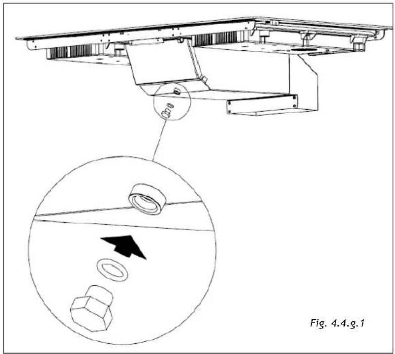
Pay attention, periodically, to the presence of liquids in the tray and empty it by removing the cap (Fig. 4.4.g.1).
It is recommended to position the container for collecting liquids under the cap.

CAUTION! Electrically disconnect the mains plug before any service operation. (Fig. 2.1 - Fig. 2.2 WARNINGS chapter)
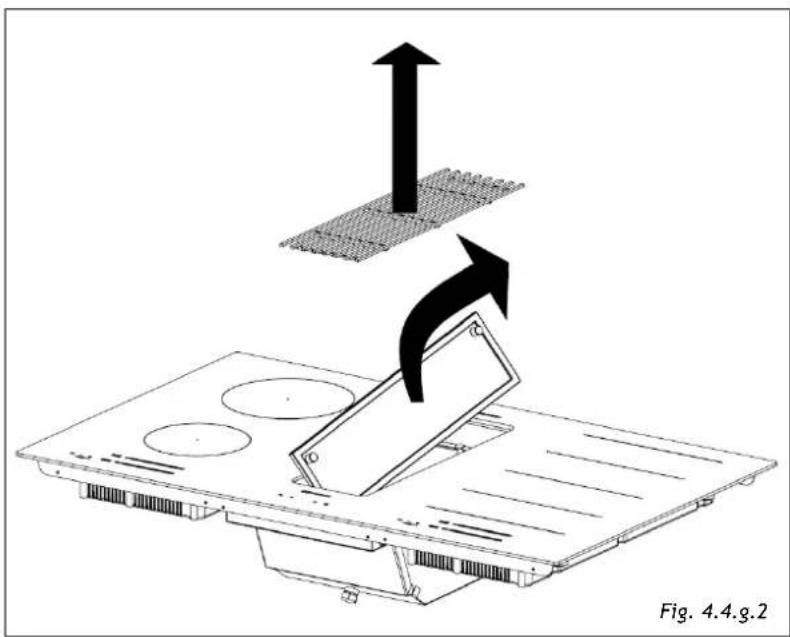
To optimize the intervention, we also recommend cleaning and drying the entire interior of the hood. Then remove the center grille in support and remove the grease filter by lifting it from the appropriate knob (Fig.4.4.g.2)
natural_image
Diagram showing a device being lifted by an upward arrow, with no text or symbols present.After doing these operations, you can clean and dry the inside of the tray from above. After cleaning, reposition all the components and the grid by performing the above operations (Fig. 4.4.g.2) in reverse order.
V CLEANING AND MAINTENANCE

CAUTION! Before any service or cleaning operation disconnect the device from the power supply (Fig.2.1-Fig.2.2 WARNINGS chapter).
V.1 INDUCTION HOB CLEANING
Switch-off the appliance before cleaning.
Do not clean the hob if the glass is too hot because they are risk of burn.
- Remove light marks with a damp cloth with washing up liquid diluted in a little water. Then rinse with cold water and dry the surface thoroughly.
- Highly corrosive or abrasive detergents and cleaning equipment likely to cause scratches must be absolutely avoided.
- Do not ever use any steam-driven or pressure appliance.
- Do not use any object that may scratch the ceramic glass.
- Ensure that the pan is dry and clean. Ensure that there are no grains of dust on your ceramic hob or on the pan. Sliding rough saucepans will scratch the surface.
- Spillages of sugar, jam, jelly, etc. must be removed immediately. You will thus prevent the surface being damaged.
V.2 COOKER HOOD CLEANING
The hood must be cleaned immediately after installing and removing the protective film in order to remove any residual glue or impurities of any kind.
The hood must be cleaned frequently both internally and externally (at least once a month).
Do not allow dirt to accumulate on the outer and inner surfaces of the hood.
The central grille can be washed in the dishwasher.
Warning! Products that are NOT to be used are:
Products containing chlorides, especially those containing hydrochloric acid;
Halide based products;
Hydrogen peroxide products;
Hypochlorous acid-based bleaches;
Acid-containing aggressive products;
Detergents containing abrasive powder;
Silver cleaning products;
Detergents whose chemical composition is unknown;
Abrasive wipes, brushes or disc;
Coarse cloths or rough paper;
Tools that have previously cleaned other metals or alloys.
Ordinary cleaning
Ordinary cleaning should be performed before excessive build-up of dirt can occur which can cause abrasive phenomena.
Before performing the washing operations, any dust particles should be removed by air or aspirated, so as to avoid rubbing on the surface.
Where water has been used as a means of cleaning or rinsing, especially in areas with significant limestone, it is recommended to dry the surface to prevent staining.
To avoid contamination caused by iron particles, make sure that the tools selected for cleaning have not previously been used on other metals or alloys.
Materials for cleaning stainless steel products must be exclusively reserved for this purpose.
Special attention should be paid to the grease filter, which has the function of retaining the fat particles contained in the vapors, and the grease collector, which has the function of collecting the fat that could fall from the grease filter. Both of these items should be washed when the relevant warning appears or at least once a month in hot water and detergent (even in dishwasher).
The filter may become discolored after washing. This is normal and does not mean it needs to be replaced.
To carry out the maintenance of the grease filter, it is essential to remove them from the hood.
To remove the metallic grease filter, proceed as indicated in the section IV.4.g PRESENCE OF LIQUIDS INSIDE THE DEVICE).
The charcoal filter, if present, must be washed or replaced when the relevant warning appears (see the section IV.4.f CHARCOAL FILTERS REPLACING ALARM).
Ask for the filter to the manufacturer.
To wash or replace the charcoal filter, check the instruction manual of the kit separately purchased.
VI WHAT TO DO IN CASE OF A PROBLEM
WARNING! During the warranty period repairs can only be carried out by authorized service staff.

CAUTION!
Before any service or maintenance, disconnect the power supply of the device (Fig.2.1 - Fig. 2.3 WARNINGS chapter)
- Unauthorized repairs or services may cause electric shock or short circuit, so do not run them. Leave these jobs to authorized personnel only.
- In the case of minor disturbances, try to solve the problem by following the instructions in the operating instructions.
- Elimination of faults or complaints caused by improper use or installation of the appliance will not be warranted. The repair costs will be borne by the user.
VI.1 ERRORS / ALARMS
The corresponding heater display alternates between two characters depend on the Error.
| Event Action Error on Display | ||
| ON-OFF Safety error | Off (*) | FA |
| Software Safety error | Off (*) | F0 |
| Capacitive key sensitivity error | Off (*) | Fb |
| NTC Short-circuit error | Off (*) | FE |
| NTC open error Off (*) Ft | ||
| Extra temperature error | Off (*) | Fc |
| Eeprom memory error | Off (*) | FH |
| PWM digital frequency signal error | Off (*) | FC |
| PWM digital signal level error | Off (*) | Fd |
| ADCMux - keyboard error | Off (*) | FJ |
| ExtMUX keyboard error | Off (*) | FU |
| Relay Output Test error | Off (*) | Fr |
Off (*) = All cooking zones are switched Off and locked
VII DISCONTINUATION, DISASSEMBLY AND WASTE DISPOSAL
VII.1 DISCONTINUATION
- Discontinuation means the definitive stop of the operation and the disassembly or the appliance.
- After discontinuation the appliance can be installed on another furniture, privately resold or disposed of.
 | CAUTION!For discontinuation it is necessary to switch the appliance off and disconnect the power (Fig. 2.1 - Fig. 2.2 WARNINGS chapter). |
 | CAUTION!Electrical disconnection and must be undertaken only by qualified service staff. |
VII.2 DISASSEMBLY
- Disassembly requires that the appliance is accessible for disassembly and has been disconnected from the power supply.
To do so, you need:
- Loose screws and fixing brackets
- Remove any silicone seals
- Disconnect the motor and the channel from the hob
- Take the top of the hob out.
VII.3 ENVIRONMENT PRESERVATION
- The materials of packing are ecological and recyclable.
- The electronic appliances are composed of recyclable, and sometimes harmful materials for the environment, but necessary to the good running and the safety of the appliance.
VII.4 WASTE DISPOSAL
natural_image
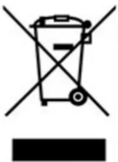
Symbol of a trash bin crossed with no text or numbers, representing waste sorting or disposal (no text present)This appliance is marked in accordance with the European Directive 2012/19/EC,
Waste Electrical and Electronic Equipment (WEEE).
The symbol on the product or on the packaging indicates that the product should not be considered as a normal household waste, but must be taken to the appropriate collection point for the recycling of electrical and electronic equipment.
By appropriately dispose of this product, it helps to avoid potential
negative consequences for the environment and health that may result
from inappropriate disposal of the product. For more detailed information on recycling this product, contact your local office, local waste disposal service, or the shop where you purchased the product.

ARTUSI
THE ART OF LIVING
Worldwide Appliances Pty Limited
A.B.N. 45868077422
Distributed by Eurolinx pty Ltd
Office:
48-50 Moore Street, Leichhardt N.S.W 2040 Post:
Locked Bag 3000, Annandale, N.S.W 2038
P: 1300 694 583
WARRANTY REGISTRATION
Your ongoing satisfaction with your artusi product is important to us. We ask that you complete the enclosed Warranty Registration Card and return it to us so that we have a record of the artusi product purchased by you.
PRIVACY
Worldwide Appliances respects your privacy and is committed to handling your personal information in accordance with the National Privacy Principles and the Privacy Act 1988 (Cth). A copy of the Worldwide Appliances Privacy Policy is available at www.artusi.com.au. Worldwide Appliances will not disclose any personal information set out in the Warranty Registration Card (“Personal Information”) without your consent unless required by:
-
law;
-
any Worldwide Appliances related company;
-
any service provider which provide services to artusi or assist artusi in providing services (including repair and warranty services) to customers. Our purpose in collecting the Personal Information is
to keep a record of the artusi product purchased by you, in order to provide a better warranty service to you in the unlikely event that there is a problem with your artusi product. Worldwide Appliances may contact you at any one or more of the address, email address or telephone numbers set out in the Warranty Registration Card. Please contact artusi on 1300 694 583 should you not wish to be contacted by Worldwide Appliances.
WARRANTY
1. Warranty
Worldwide Appliances warrants that each artusi product will remain, for a period of either 12 months or 24 months of warranty. All Warranties are valid from the original date of purchase, And warranty claims must be accompanied by the proof of purchase.
24 months warranty products:
All Built-in Appliances – Limited to Ovens, Gas, Induction and Electric Cooktops, and All Rangehoods. Freestanding Cookers - Gas and Electric Models (900mm Width).
Dishwashers - Freestanding, Fully Integrated, Semi Integrated and built-in. All Wine coolers. All Dryers. Freestanding Cookers - Gas and Electric Models in 50cm, 54cm and 60cm Widths
Portable Appliances* – Benchtop Models and Portable Gas Models
2. What is not Covered by the Warranty.
The Warranty does not apply if an artusi product is defective by a factor other than a defect arising in the manufacture of the artusi product, including but not limited to:
(a) damage through misuse (including failure to maintain, service or use with proper care), neglect, accident or ordinary wear and tear (including deterioration of parts and accessories and glass breakage);
(b) use for purpose for which the artusi product was not sold or designed;
(c) use or installation which is not in accordance with any specified instructions for use or installation;
(d) use or operation after a defect has occurred or been discovered;
(e) damage through freight, transportation or handling in transit (other than when Worldwide Appliances is responsible);
(f) damage through exposure to chemicals, dusts, residues, excessive voltage, heat, atmospheric conditions or other forces or environmental factors outside the control or Worldwide Appliances;
(g) repair, modification or tampering by the purchaser or any person other than Worldwide Appliances, an employee of Worldwide Appliances or an authorised artusi service contractor ^* ;
(h) use of parts, components or accessories which have not been supplied or specifically approved by artusi.
(i) damage to surface coatings caused by cleaning or maintenance using products not recommended in the artusi product handbook provided to the purchaser upon purchase of the artusi product;
(j) damage to the base of an electric oven due to items having been placed on the base of the oven cavity or covering the base, such as aluminium foil (this impedes the transfer of heat from the element to the oven cavity and can result in irreparable damage); or
(k) damages, dents or other cosmetic imperfections not affecting the performance of the artusi in respect of an artusi product purchased as a “factory second” or from display
The Warranty does not extend to light globes used in artusi products.
3. Domestic Use
Each artusi product is made for domestic use.
This Warranty may not extend to artusi products used for commercial purposes.
Continued over...
4. Time for Claim under the Warranty
You must make any claim under this Warranty within twenty eight (28) days after the occurrence of an event which gives rise to a claim pursuant to the Warranty, by booking a service call on the telephone number below.
5. Proof of Purchase
Customers must retain proof of purchase in order to be eligible to make a warranty claim in respect of an artusi product.
6. Claiming under the Warranty
Customers will bear the cost of claiming under this Warranty unless Worldwide Appliances determines the expenses are reasonable, in which case the customer must claim those expenses by providing written evidence of each expense to Worldwide Appliances at the address on the Warranty Registration Card.
7. Statutory Rights
(a) These terms and conditions do not affect your statutory rights.
(b) The limitations on the Warranty set out in this document do not exclude or limit the application of the consumer guarantees set out in the Act or any other equivalent or corresponding legislation in the relevant jurisdiction where to do so would:
(i) contravene the law of the relevant jurisdiction; or
(ii) cause any part of the Warranty to be void.
(c) Worldwide Appliances excludes indirect or consequential loss of any kind (including, without limitation, loss of use of the artusi product) and (other than expressly provided for in these terms and conditions) subject to all terms,
conditions and warranties implied by custom, the general law, the Act or other statute.
(d) The liability of Worldwide Appliances to you
Warranty Card tear off
for a breach of any express or non-excludable implied term, condition or warranty is limited at the option of Worldwide Appliances to:
(i) replacing or repairing the defective part of the artusi product;
(ii) paying the cost of replacing or repairing the defective part of the artusi product;
(iii) replacing the artusi product; or
(iv) paying the cost of replacing the artusi product.
(e) Our goods come with guarantees that cannot be excluded under the Australian Consumer Law. You are entitled to a replacement or refund for a major failure and for compensation for any other reasonably foreseeable loss or damage.
You are also entitled to have the goods repaired or replaced if the goods fail to be of acceptable quality and the failure does not amount to a major failure.
8. Defects
Any part of an artusi product deemed to be defective and replaced by Worldwide Appliances is the property of Worldwide Appliances. Worldwide Appliances reserves the right to inspect and test artusi products in order to determine the extent of any defect and the validity of a claim under the Warranty.
All warranty service calls must be booked via the customer care department. The team can be contacted on 1 300 85 64 11 option 1 or customercare@eurolinx.com.au
01082016

ARTUSI
THE ART OF LIVING
WARRANTY REGISTRATION CARD
01052016
Please complete and send to ARTUSI at: REPLY PAID 83617 LEICHHARDT NSW 2040
| Last Name: First Name: | ||
| Address: | ||
| State: Postcode: Email: | ||
| Home Phone: Mobile: | ||
| Purchase Date: / / (Please attach proof of purchase to validate warranty) | ||
| MODEL NUMBER | SERIAL NUMBER(if you cannot locate the serial number please call ARTUSI on 1300 856 411) |
| 1 | |
| 2 | |
| 3 | |
| 4 |

ARTUSI
THE ART OF COOKING
DISCLAIMER
Worldwide Appliances PTY LTD, trading as ARTUSI, is continually seeking ways to improve the design specifications, aesthetics and production techniques of its products. As a result alterations to our products and designs take place continually. Whilst every effort is made to produce information and literature that is up to date, this brochure should not be regarded as an infallible guide to the current specifications, nor does it constitute an offer for the sale of any particular product. Product dimensions indicated in our literature is indicative only. Actual product only should be used to define dimension cutouts. Distributors, and retailers are not agents of ARTUSI and are not authorised to bind ARTUSI by any express or implied undertaking or representation.
ARTUSIOFFICES ARE OPEN DAILY FROM 9AM-5PM AND SATURDAYS 10AM-4PM
NSW & ACT (HEAD OFFICE)
48-50 MOORE STREET
LEICHHARDT
FO285694699
VIC. TAS & SA
2R/131 CHURCH ST
HAWTHORN
QLD
1/42 CAVENDISH ROAD
COORPAROO
FO733970850
WA&NT
UNIT 10/55 HOWE STREET
OSBORNE PARK
F0892019188
NZ
PO BOX 11.160
SOCKBURN CHRISTCHURCH
FO33445906
- Safety Warnings INDD94 & AID864DD
- Chapters
- GENERAL
- II WARNINGS
- Precautions before using
- Using the appliance
- Precautions not to damage the appliance
- Precautions in case of appliance failure
- Other protections
- III INSTALLATION
- III.1 PRELIMINARY INDICATIONS
- III.2 INSTALLATION
- III.2.a INDUCTION HOB INSTALLATION
- How to stick the gasket:
- Fitting - installing:
- III.2.b ASPIRATION INSTALLATION
- III.3 ELECTRICAL CONNECTION
- These appliances must be earthed.
- Caution!
- Aspirator connection procedure:
- IV OPERATION
- IV.1 DESCRIPTION OF THE INDUCTION HOB
- IV.1.a TECHNICAL CHARACTERISTICS
- Power level detail:
- IV.1.b BASIC CONTROL CHARACTERISTICS
- GENERAL KEYS
- HEATER KEYS
- BUZZER SOUNDS
- IV.2 USE OF THE INDUCTION HOB
- IV.2.a AUTO-LOCK
- IV.2.b SWITCH ON/OFF THE COOKTOP
- IV.2.d SWITCH OFF A HEATER ZONE
- IV.2.e SELECTION OF HEATER'S TIMER /WARM FUNCTION
- IV.2.f INCREASE / DECREASE POWER LEVEL WITH SLIDER
- IV.2.g BOOSTER FUNCTION
- IV.2.h BRIDGE FUNCTION
- IV.2.i HEAT-UP FUNCTION
- IV.2.1 SECURITY
- IV.2.n TIMER
- IV.2.o AUTOMATIC SAFETY OFF
- IV.2.p RESIDUAL HEAT INDICATION
- IV.2.r DISPLAYING SPECIAL STATUSES IN TOUCH CONTROL
- IV.3 COOKIG ADVICES
- IV.3.a PAN QUALITY
- IV.3.b PAN DIMENSION
- IV.4.a ASPIRATION TURN ON
- IV.4.c CLEANING FUNCTION
- IV.4.d ADJUSTABLE AND DELAYED SELF-SWITCHING OFF
- IV.4.e ANTI GREASE FILTER CLEANING ALARM
- IV.4.f CHARCOAL FILTERS REPLACING ALARM
- IV.4.g PRESENCE OF LIQUIDS INSIDE THE DEVICE
- V CLEANING AND MAINTENANCE
- V.1 INDUCTION HOB CLEANING
- Switch-off the appliance before cleaning.
- V.2 COOKER HOOD CLEANING
- Warning! Products that are NOT to be used are:
- Ordinary cleaning
- VI WHAT TO DO IN CASE OF A PROBLEM
- VI.1 ERRORS / ALARMS
- VII DISCONTINUATION, DISASSEMBLY AND WASTE DISPOSAL
- VII.1 DISCONTINUATION
- VII.2 DISASSEMBLY
- VII.3 ENVIRONMENT PRESERVATION
- VII.4 WASTE DISPOSAL
- ARTUSI
- THE ART OF LIVING
- Worldwide Appliances Pty Limited
- WARRANTY REGISTRATION
- PRIVACY
- WARRANTY
- Warranty
- months warranty products:
- What is not Covered by the Warranty.
- Domestic Use
- Time for Claim under the Warranty
- Proof of Purchase
- Claiming under the Warranty
- Statutory Rights
- Warranty Card tear off
- Defects
- THE ART OF COOKING
- DISCLAIMER
Brand : Artusi
Model : AID864DD
Category : Cooker