301135 - TV antenna Wilson - Free user manual and instructions
Find the device manual for free 301135 Wilson in PDF.


| Product Type | Dual-Band Panel Antenna for cellular signal boosting |
| Frequency Range | 800-960 MHz / 1710-2500 MHz |
| Impedance | 50 ohms |
| Gain | 7 dBi (low band) / 10 dBi (high band) |
| Polarization | Vertical |
| Beamwidth (Horizontal) | 70° (low band) / 60° (high band) |
| Beamwidth (Vertical) | 50° (low band) / 45° (high band) |
| VSWR | < 1.5 |
| Maximum Power | 50 watts |
| Connector Type | N-Female |
| Dimensions (H x W x D) | 8.27 x 7.09 x 1.73 in (21 x 18 x 4.39 cm) |
| Weight | 1.32 lbs (0.6 kg) |
| Installation Methods | Window mount (with suction cups or tape) or wall mount (with bracket and screws) |
| Minimum Installation Height | 7 feet above floor |
| Included Accessories (Model 301135) | Mounting bracket, screws, installation template (wall mount kit) |
| Warranty | 90 days against defects; 30-day money-back guarantee |
| Cleaning | Clean window and suction cups with alcohol swab before installation |
| Safety Note | Use firm, even pressure to avoid breaking glass; install cable vertically for optimal signal |
Frequently Asked Questions - 301135 Wilson
User questions about 301135 Wilson
0 question about this device. Answer the ones you know or ask your own.
Ask a new question about this device
Download the instructions for your TV antenna in PDF format for free! Find your manual 301135 - Wilson and take your electronic device back in hand. On this page are published all the documents necessary for the use of your device. 301135 by Wilson.
USER MANUAL 301135 Wilson
Antenna Installation Guide
Dual-Band Panel Antenna
PART# 301134
PART# 301135
PART# 301147
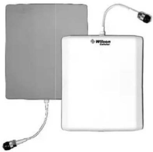
natural_image
Two electronic devices, one gray and one white, with visible wiring and connectors (no text or symbols on the devices themselves)Contents:
• Dual-Band Panel Antenna
- Two-sided tape (301134)
• Alcohol swab (301134)
• Coax cable (301147)
- Antenna installation kit (301135 & 301147)
The dual-band panel antenna is vertically polarized. For optimum performance, install the antenna with the cable running from the bottom or the top. If the antenna is installed with the N-connector or cable running horizontally, the signal will be degraded.
30-Day Money-Back Guarantee
All Wilson Electronics products are protected by Wilson's 30-day money-back guarantee. If, for any reason, the performance of any product is not acceptable, simply return the product directly to the reseller with a dated proof of purchase.
90-Day Warranty
Wilson Electronics antennas are warranted for ninety (90) days against defects in workmanship and / or materials. Warranty cases may be resolved by returning the product directly to the reseller with a dated proof of purchase.
Antennas may also be returned directly to the manufacturer at the consumer's expense, with a dated proof of purchase and a Returned Material Authorization (RMA) number supplied by Wilson Electronics. Wilson shall, at its option, either repair or replace the product. Wilson Electronics will pay for delivery of the repaired or replaced product back to the original consumer.
This warranty does not apply to any antennas determined by Wilson Electronics to have been subjected to misuse, abuse, neglect, or mishandling that alters or damages physical or electronic properties.
RMA numbers may be obtained by phoning Technical Support at 866-294-1660.
Disclaimer: The information provided by Wilson Electronics, Inc. is believed to be complete and accurate. However, no responsibility is assumed by Wilson Electronics, Inc. for any business or personal losses arising from its use, or for any infringements of patents or other rights of third parties that may result from its use.
Window Installation Instructions (part # 301134)
natural_image
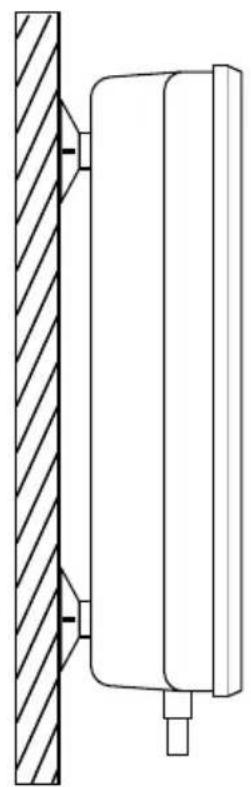
Technical line drawing of a mechanical assembly with hatched vertical and horizontal components (no text or symbols)Find the window that faces the direction of the nearest cell tower. The signal strength function on your cell phone can help you determine this. See the Technical Support section of Wilson's website (www.wilsonelectronics.com) for instructions on accessing the signal strength function on your particular phone.
Choose the location on the window where the antenna will be hung. The panel antenna must be installed at least seven feet above the floor. Clean the window and the suction cups with the alcohol swab.
It is important that the small tabs on each suction cup be facing outward so they may be used to remove the antenna from the window if desired. Use fi rm and even pressure to attach the antenna to the window without breaking the glass. Avoid excessive or sudden pressure against the glass.
For a more permanent installation, remove the suction cups and use the two-sided tape to affi x the antenna.
Wall Installation Instructions (part # 301135 & 301147)
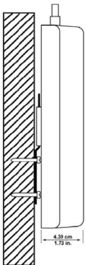
Find the desired location for the panel antenna. Verify that the panel antenna and the outside antenna have the necessary separation (see amplifier instructions for requirements.)
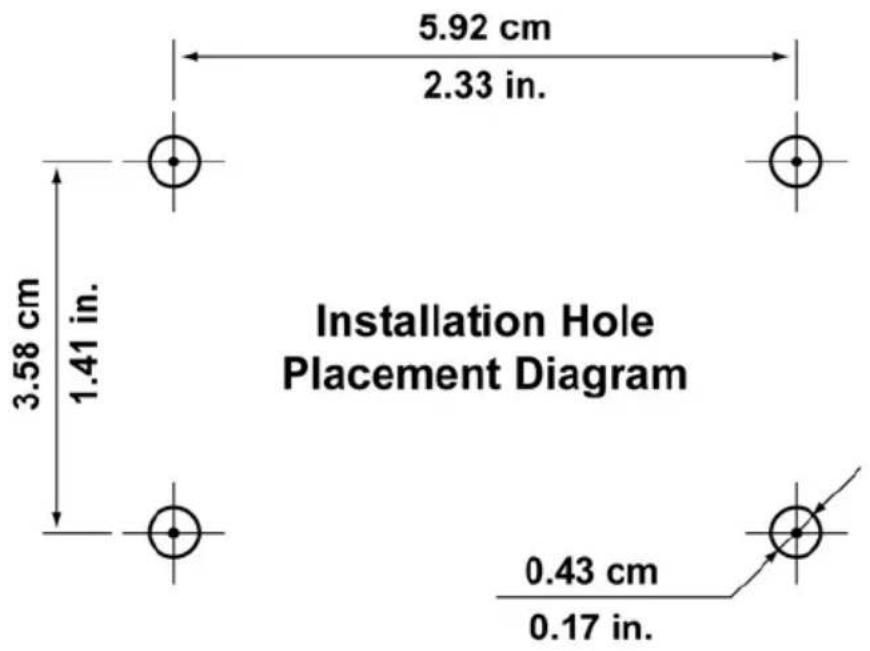
The panel antenna must be installed at least seven feet above the floor. Place the diagram where the panel antenna is to be installed.
Attach the diagram with masking tape or other suitable adhesive tape.
Drill out the four holes as indicated on the template. Place the mounting bracket over the holes and insert the screws. Slide the panel onto the installation bracket.
For questions or comments, please contact Technical Support toll free at 866-294-1660, email tech@wilsonelectronics.com or visit www.wilsonelectronics.com
Antenna Specifications
| Part Number 301134 | 301135 301147 | ||
| Frequency Range 800-960 MHz / 1710-2500 MHz | |||
| Impedance 50 ohms | |||
| Gain 7 dBi / 10 dBi | |||
| Polarization Vertical | |||
| Beamwidth Horizontal Plane 70 / 60 | |||
| Beamwidth Vertical Plane 50 / 45 | |||
| VSWR < 1.5 | |||
| Max Power 50 watts | |||
| Connector N-Female | |||
| Dimension 8.27 x 7.09 x 1.73 (inch) / 21 x 18 x 4.39 (cm) | |||
| Weight | 1.32 lbs / 0.6 kg | ||
Wilson Amplifiers Boost Coverage
When used in conjunction with your antenna, a Wilson Amplifier can improve your cell phone and laptop data card coverage area up to 50 miles. Wilson manufactures a wide range of wireless and direct-connection amplifiers for mobile or in-building use. See your dealer for details or visit www.wilsonelectronics.com.


Wilson®
Electronics, Inc.
3301 East Deseret Drive, St. George UT 84790
For additional Technical Support visit
www.wilsonelectronics.com
Phone: 866-294-1660
Fax: 435-656-2432
Brand : Wilson
Model : 301135
Category : TV antenna