
MZU 2008 - Uncategorized FBT - Free user manual and instructions
Find the device manual for free MZU 2008 FBT in PDF.


| Product Type | Active Loudspeaker |
| Brand | FBT |
| Model | MZU 2008 |
| Dimensions (W x H x D) | 450 mm x 300 mm x 280 mm |
| Weight | 15 kg |
| Power Handling (RMS) | 300 W |
| Impedance | 8 ohms |
| Frequency Response | 60 Hz - 20 kHz |
| Sensitivity (1W/1m) | 95 dB |
| Input Connectors | XLR, 1/4" Jack, Speakon |
| Enclosure Material | Plywood |
| Grille | Metal |
| Mounting Options | Pole mount, floor monitor |
| Color | Black |
| Power Supply | 100-240 V AC, 50/60 Hz |
| Cleaning Instructions | Use a dry cloth; avoid solvents |
| Safety Precautions | Do not expose to moisture or extreme temperatures |
Frequently Asked Questions - MZU 2008 FBT
User questions about MZU 2008 FBT
0 question about this device. Answer the ones you know or ask your own.
Ask a new question about this device
Download the instructions for your Uncategorized in PDF format for free! Find your manual MZU 2008 - FBT and take your electronic device back in hand. On this page are published all the documents necessary for the use of your device. MZU 2008 by FBT.
USER MANUAL MZU 2008 FBT
Control unit for 4 inputs into 4 outputs: provides fast and simple zone configuration, eliminating the need for laborious rewiring.
Constant monitoring of inputs and outputs on VU-meters and headphones.
N. 4 dedicated line exclusion controls to disable loudspeakers in the vicinity of microphones in order to eliminate feedback problems.
Zones can be personalized using self-adhesive labels.
* 4 0dB inputs on terminals
* 4 0dB outputs on terminals
* 4 inserts for external equipment
* 4 pushbuttons for each input, with LEDs indicating selected output
* 1 monitor button with LED on each input
* 1 button with LED for loudspeaker inhibition (on prearranged line)
MZU2008
It's a management unit for setting the zones in which the music can go on, interrupting only those interested in the announcement, simply by pushing buttons on the front panel, with a light indication.
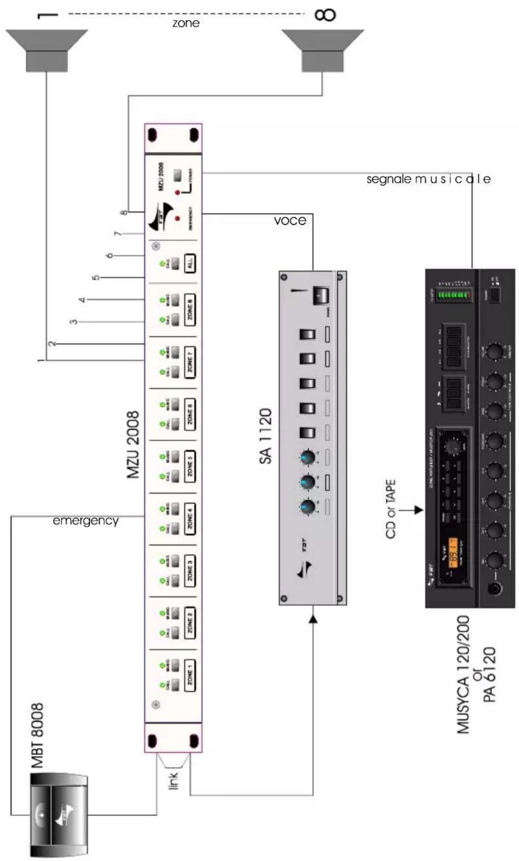
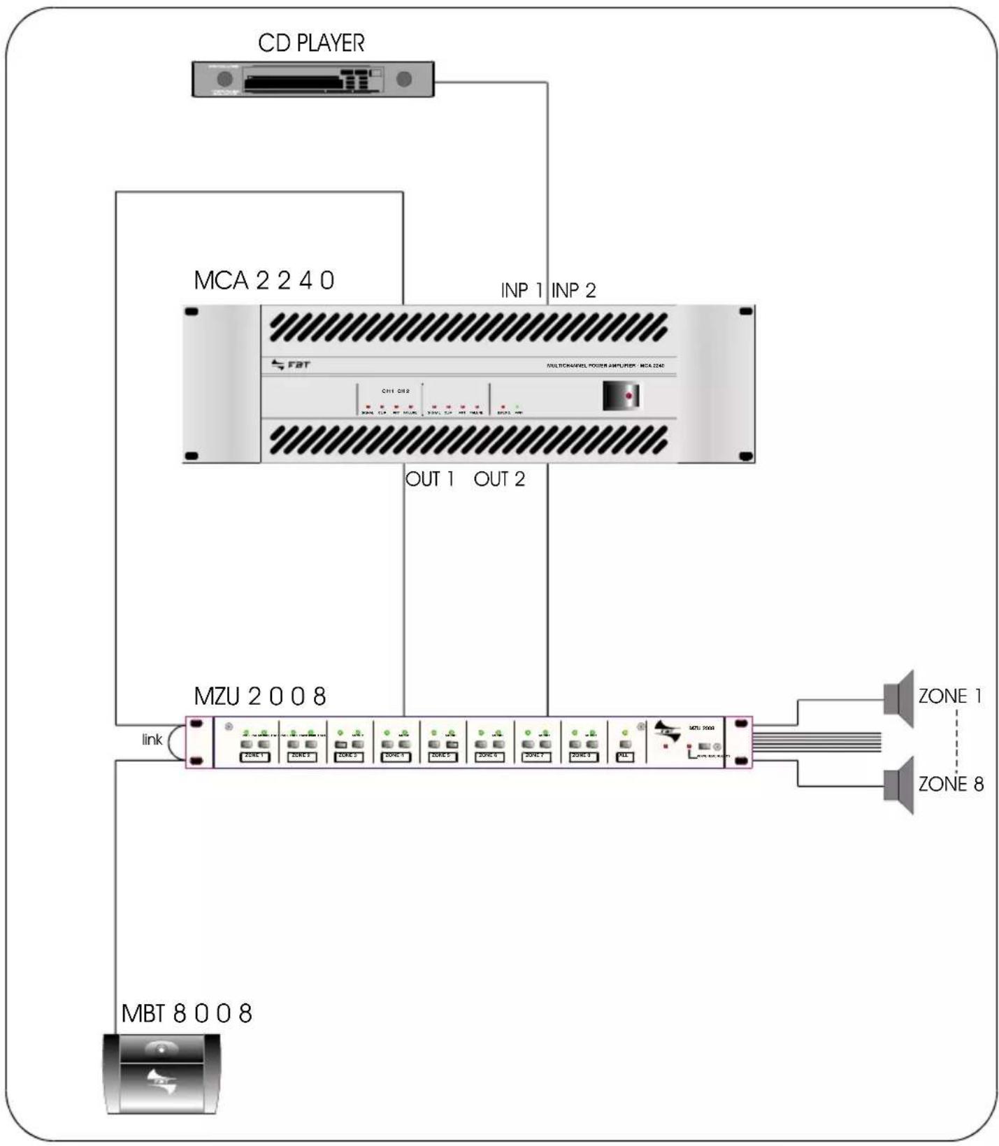
The zone paging can be remote-controlled by a desk-topmicrophone base, such as MBT8008.
I | UK
IMPORTANTE
Before connecting and using the equipment, read the instructions in this manual carefully.
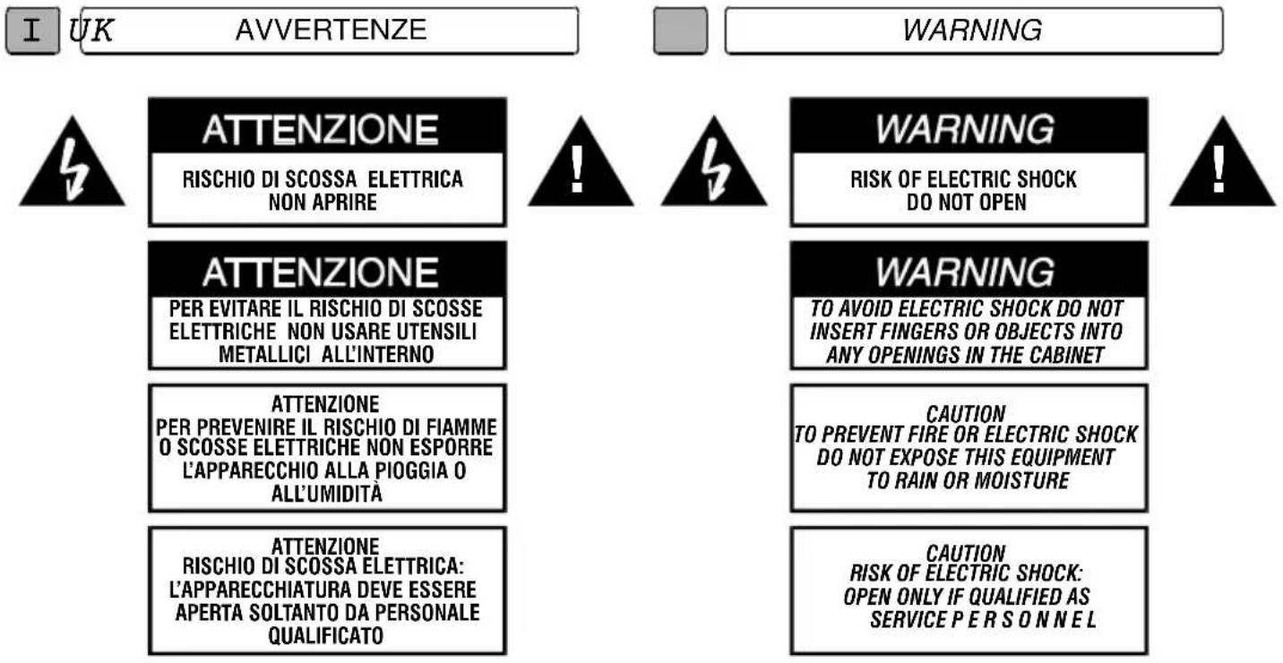
Read the notes preceded by this symbol with special attention as they provide important safety information.

WARNING
° When connecting external appliances as a sound system chain (mixer, power amplifier, electronic equipment, etc...) Some noise (hum) or buzz may be heard: in general, the cause is to ascribe to earth loops. The most effective way to avoid such disturbance consists in connecting the earth of the various audio appliances to one specific point (star connection), or cut out the balanced signal shield only from one side.
° Do not force the control knobs or pushbuttons: they are designed to respond to light pressure and could be damage if pressed too hard.
° Do not use solvents such as acetone or alcohol to clean the mixer, as they would damage its finish and the writing on its panels.
° In the event of malfunction of any part of the system, contact the nearest assistance centre, but never try to carry out repairs yourself.
The mixer is fed with an external adapter with double insulation, supplying low voltage and guaranteeing a high degree of safety for the user.
The external feeder must be positioned so that: - it does not come into contact with sharp metal bodies that can perforate the container;
- it is distant from the input circuits and the screened cables of the signal connections;
- the feed cable is not squashed or cut.
INSTALLAZIONE
Although it is neither complicated to install nor difficult to operate your amplifier, a few minutes of your time is required to read this manual for a properly wired installation and becoming familiar with its many features and how to use them. Please take a great care in unpacking your set and do not discard the carton and other packing materials: they may be needed when moving your set and are required if it ever becomes necessary to return your set for services. Never place the unit near radiator, in front of heating vents, to direct sunlight, in excessive humid or dusty location to avoid early damage and for your years of quality use.
Connect your complementary components as illustrated in the following pages.
° When the unit is installed in a rack enclosure, the rack must have all the prerequisites required by the EN 60439-1 standard, in particular the rear part must be closed by means of suitable panels.
COLLEGAMENTI CONNECTIONS
° Before using the amplifier for the first time make sure that the appliance's voltage is in accordance to your mains supply. Connect the unit only to grounded mains outlets.
° The unit must only be supplied from the mains after all connections have been completed and re-checked all the connections

PANNELLO ANTERIORE
MMS 4004
FRONT PANEL

flowchart
graph TD
    A["1"] --> B["INPUT A"]
    B --> C["INPUT B"]
    C --> D["INPUT C"]
    D --> E["INPUT D"]
    E --> F["HEAD SPEAKERS"]
    F --> G["MONITORS"]
    G --> H["dB -20-15-10 -7 -5 -3 -1 0 1 3 5 8"]
    H --> I["MMS 4004"]
    I --> J["VOLUME ON PWR"]

    subgraph Inputs
        Z1["Z1"] & Z2["Z2"] & Z3["Z3"] & Z4["Z4"] & MON["Z4"]
    end

    subgraph Outputs
        Z1a["Z1"] & Z2a["Z2"] & Z3a["Z3"] & Z4a["Z4"] & MONa["Z4"]
    end

    subgraph Outputs
        Z1b["Z1"] & Z2b["Z2"] & Z3b["Z3"] & Z4b["Z4"] & MONb["Z4"]
    end

    subgraph Outputs
        Z1c["Z1"] & Z2c["Z2"] & Z3c["Z3"] & Z4c["Z4"] & MONc["Z4"]
    end

    subgraph Outputs
        Z1d["Z1"] & Z2d["Z2"] & Z3d["Z3"] & Z4d["Z4"] & MONd["Z4"]
    end

    subgraph Outputs
        Z1e["Z1"] & Z2e["Z2"] & Z3e["Z3"] & Z4e["Z4"] & MONe["Z4"]
    end

    subgraph Outputs
        Z1f["Z1"] & Z2f["Z2"] & Z3f["Z3"] & Z4f["Z4"] & MONf["Z4"]
    end

    subgraph Outputs
        Z1g["Z1"] & Z2g["Z2"] & Z3g["Z3"] & Z4g["Z4"] & MONg["Z4"]
    end

    subgraph Outputs
        Z1h["Z1"] & Z2h["Z2"] & Z3h["Z3"] & Z4h["Z4"] & MONh["Z4"]
    end

    subgraph Outputs
        Z1i["Z1"] & Z2i["Z2"] & Z3i["Z3"] & Z4i["Z4"] & MONi["Z4"]
    end

    subgraph Outputs
        Z1j["Z1"] & Z2j["Z2"] & Z3j["Z3"] & Z4j["Z4"] & MONj["Z4"]
    end

    subgraph Outputs
        Z1k["Z1"] & Z2k["Z2"] & Z3k["Z3"] & Z4k["Z4"] & MONk["Z4"]
    end

    subgraph Outputs
        Z1l["Z1"] & Z2l["Z2"] & Z3l["Z3"] & Z4l["Z4"] & MONl["Z4"]
    end

    subgraph Outputs
        Z1m["Z1"] & Z2m["Z2"] & Z3m["Z3"] & Z4m["Z4"] & MONm["Z4"]
    end

    subgraph Outputs
        Z1n["Z1"] & Z2n["Z2"] & Z3n["Z3"] & Z4n["Z4"] & MONn["Z4"]
    end

    subgraph Outputs
        Z1o["Z1"] & Z2o["Z2"] & Z3o["Z3"] & Z4o["Z4"] & MONo["Z4"]
    end

    subgraph Outputs
        Z1p["Z1"] & Z2p["Z2"] & Z3p["Z3"] & Z4p["Z4"] & MONp["Z4"]
    end

    subgraph Outputs
        Z1q["Z1"] & Z2q["Z2"] & Z3q["Z3"] & Z4q["Z4"] & MONq["Z4"]
    end

    subgraph Outputs
        Z1r["Z1"] & Z2r["Z2"] & Z3r["Z3"] & Z4r["Z4"] & MONr["Z4"]
    end

    subgraph Outputs
        Z1g["C"]
        z["a"][b][c][d][e][f][g][h][i][j][k][l][m][n][o][p][q][r][s][t][u][v][w][x][y][z][w][w]
PANNELLO POSTERIORE
REAR PANEL

[1] Switches for assigning the input to the corresponding output (zones 1-4 and monitor). Turning on is signalled by the LED coming on.
[2] Switches for turning on the 4 open collectors (10) located on the back panel, able to control as many relays (max. absorption 100mA for each load). See example on page 14.
[3] Switches for sending the signal to the monitor coming from zones 1, 2, 3, 4. The "INPUTS A-B-C-D" indicator indicates that the signal sent to the monitor comes from one or more inputs (A-B-C-D); in this case the signals coming from the outputs Z1, Z2, Z3, Z4 cannot go to the monitor.
The "EMERGENCY" LED indicates turning on of the Emergency control (9) located on the back panel.
[4] VU-meter with 12 LEDs for displaying the level of the signal sent to themonitor
[5] Dial potentiometer for adjusting the monitor volume
[6] Stereo jack for connecting an earphone; inserting the jack in the socket turns off the output for the auxiliary speaker (13).
[7] Switch for turning on the system.
CONTROLS AND FUNCTIONS
FRONT PANEL REAR PANEL
[8] Terminal boards enabling the balanced connection of four input signals. See example on page 14.
[9] Input/output for turning on the emergency.
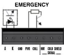
[10] Four open collectors that can be turned on by means of switches (1) located on the front panel, and which can directly control as many relays (100mA max. absorption each) to be used for turning off speakers interfering with themicrophones, for starting motors, etc.
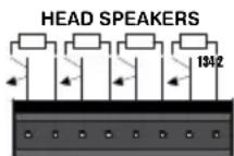
PMR PMR PMR PVRLLOAD LOAD LOAD LOAD
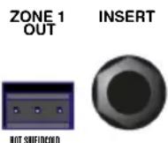
[11] Stereo jack for connecting an external equalizer, noise gate, limiter, etc., to the relative zone (see example on page 14)
[12] 3 pin connector; balanced signal outputs of the relative zones (see example on page 14)
[13] Connector for connecting a monitor
AUX SPKR
Z min 8 ohm

[14] Outlet for connecting the external feeder.
AC POWER
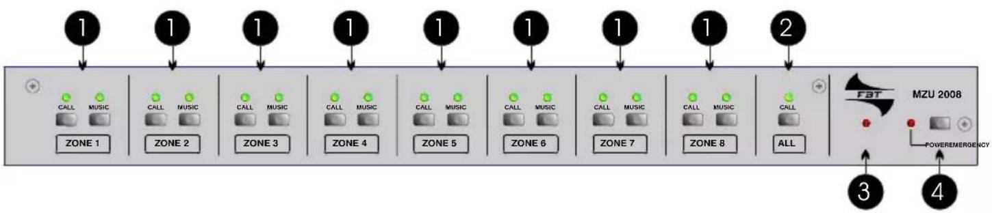
PANNELLO ANTERIORE MZU 2008
FRONT PANEL
flowchart
graph LR
    A["1"] --> B["ZONE 1"]
    C["1"] --> D["ZONE 2"]
    E["1"] --> F["ZONE 3"]
    G["1"] --> H["ZONE 4"]
    I["1"] --> J["ZONE 5"]
    K["1"] --> L["ZONE 6"]
    M["1"] --> N["ZONE 7"]
    O["1"] --> P["ZONE 8"]
    Q["2"] --> R["ALL"]
    S["3"] --> T["MZU 2008"]
    U["4"] --> V["POWEREMERGENCY"]
    style A fill:#f9f,stroke:#333
    style C fill:#f9f,stroke:#333
    style E fill:#f9f,stroke:#333
    style G fill:#f9f,stroke:#333
    style I fill:#f9f,stroke:#333
    style M fill:#f9f,stroke:#333
    style Q fill:#f9f,stroke:#333
    style S fill:#f9f,stroke:#333
    style U fill:#f9f,stroke:#333
    style V fill:#f9f,stroke:#333
[1] Turning on for the music or voice selected zone; starting is indicated by the corresponding LED coming on.
[2] The call switch turns on the “speech” function in all zones, excluding the assigning of music.
[3] Coming on of the emergency LED indicates turning on of the emergency function.
[4] Switch for turning on the system with relative indicator light.
PANNELLO POSTERIORE
REAR PANEL

CONTROLS AND FUNCTIONS
FRONT PANEL REAR PANEL
[5] Terminal board enabling the mechanical reintroduction of the wires relative to the signal and priorities coming from a table base. See example on page 15.
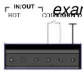
SIGNAL
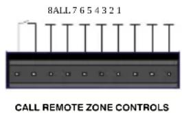
[6] Terminal board enabling connection of the remote control of the zones. See page 15.
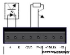
[7] Input/output for turning on the emergency and input for particular signals.
[8] Terminal board with three wires for connecting the lines of speakers in the eight zones. See page 15.
LINECOM EMERG
ZONE 8
[9] Terminal board for connecting the output of the specific power amplifier for call. See page
INPUT 15. LINE COM EMERG.
[10] Terminal board enabling connection of the output of the specific power amplifier for music. See page 15.
INPUT LINE COM

[11] Outlet for external feeder.


flowchart
graph LR
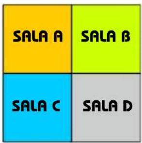
    A["SALA A"] --> B["MMS 4004"]
    C["SALA B"] --> B
    D["SALA C"] --> B
    E["SALA D"] --> B
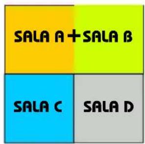
    B --> F["+"]
    F --> G["SALA A + SALA B"]
    F --> H["SALA B + SALA A"]
    F --> I["SALA C + SALA A + SALA B + SALA C"]
    F --> J["SALA C + SALA A + SALA B + SALA D"]
    F --> K["SALA D + SALA A + SALA B + SALA C"]
    G --> L["+"]
    H --> M["+"]
    I --> N["+"]
    J --> O["+"]
    K --> P["+"]
    L --> Q["SALA A + SALA C + SALA D"]
    M --> R["SALA B + SALA C + SALA D"]
    N --> S["SALA C + SALA A + SALA B + SALA D"]
    O --> T["SALA D + SALA A + SALA B + SALA C"]
    P --> U["SALA D + SALA A + SALA B + SALA D"]
    Q --> V["SALA A + SALA C + SALA D"]
    R --> W["SALA B + SALA C + SALA D"]
    S --> X["SALA C + SALA A + SALA B + SALA D"]
    T --> Y["SALA D + SALA A + SALA B + SALA D"]
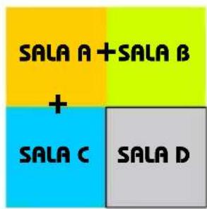
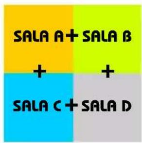
flowchart
graph TD
    MBT_8008["MBT 8008"] -->|link| Z0_ZONE_1["ZONE 1"]
    MBT_8008 -->|emergency| MZU_2008["MZU 2008"]
    MZU_2008 -->|volume| SA_1120["SA 1120"]
    SA_1120 -->|CD or TAPE| MUSYCA_120/200["MUSYCA 120/200 OF PA 6120"]
    MUSYCA_120/200 -->|segndle musiccle| MZU_2008
    MZU_2008 -->|band output| MZU_2008
    MZU_2008 -->|band output| MZU_2008
    MZU_2008 -->|band output| MZU_2008
    MZU_2008 -->|band output| MZU_2008
    MZU_2008 -->|band output| MZU_2015["band output"]
    MZU_2015 -->|band output| MZU_2015
    MZU_2015 -->|band output| MZU_2015
    MZU_2015 -->|band output| MZU_2015
    MZU_2015 -->|band output| MZU_2015
    MZU_2015 -->|band output| MZU_2015
    MZU_2025["SA 1120"]
    MZU_2025 -->|band output| MZU_2025
    MZU_2025 -->|band output| MZU_2025
    MZU_2025 -->|band output| MZU_2025
    MZU_2025 -->|band output| MZU_2025
    MZU_2025 -->|band output| MZU_2035["SA 1120"]
    MZU_2035 -->|band output| MZU_2035
    MZU_2035 -->|band output| MZU_2035
    MZU_2035 -->|band output| MZU_2035
    MZU_2035 -->|band output| MZU_2045["SA 1120"]
    MZU_2045 -->|band output| MZU_2045
    MZU_2045 -->|band output| MZU_2045
    MZU_2045 -->|band output| MZU_2045
    MZU_2045 -->|band output| MZU_2045
    MZU_2045 -->|band output| MZU_2045
    MZU_2067["SA 1120"]
    MZU_2067 -->|band output| MZU_2067
    MZU_2067 -->|band output| MZU_2067
    MZU_2067 -->|band output| MZU_2067
    MZU_2067 -->|band output| MZU_2067
    MZU_2067 -->|band output| MZU_2067
    MZU_2079["SA 1120"]
    MZU_2079 -->|band output| MZU_2079
    MZU_2079 -->|band output| MZU_2079
    MZU_2079 -->|band output| MZU_2079
    MZU_2079 -->|band output| MZU_2079
    MZU_2079 -->|band output| MZU_2079
    MZU_2133["SA 1120"]
    MZU_2133 -->|band output| MZU_2133
    MZU_2133 -->|band output| MZU_2133
    MZU_2133 -->|band output| MZU_2133
    MZU_2133 -->|band output| MZU_2133
    MZU_2133 -->|band output| MZU_2133
    MZU_2146["SA 1120"]
    MZU_2146 -->|band output| MZU_2146
    MZU_2146 -->|band output| MZU_2146
    MZU_2146 -->|band output| MZU_2146
    MZU_2146 -->|band output| MZU_2146
    MZU_2146 -->|band output| MZU_2146
    MZU_2169["SA 1120"]
    MZU_2169 -->|band output| MZU_2169
    MZU_2169 -->|band output| MZU_2169
    MZU_2169 -->|band output| MZU_2169
    MZU_2169 -->|band output| MZU_2169
    MZU_2173["SA 1120"]
    MZU_2173 -->|band output| MZU_2173
    MZU_2173 -->|band output| MZU_2173
    MZU_2173 -->|band output| MZU_2173
    MZU_2173 -->|band output| MZU_2173
    MZU_2173 -->|band output|
    MZU_3444["SA 1120"]
    MZU_3444 -->|band output| MZU_3444
    MZU_3444 -->|band output|
    MZU_3444 -->|band output|
    MZU_3444 -->|band output|
    MZU_3444 -->|band output|
    MZU_3444 -->|band output|
    MZU_3444 -->|band output|
    MZU_3444 -->|band output|
    MZU_3444 -->|band output|
    NZE 8.8.8.8.8.8.8.8.8.8.8.8.8.8.8.8.8.8.8.8.8.8.8.8.8.8.8.8.8.8.8.8.8.8.8.8.8.8.8.8.8.8.8.8.8.8.8.8.8.8.8.
flowchart
graph TD
    subgraph MMS_4004
        A["INPUT A"] --> B["INPUT B"]
        B --> C["INPUT C"]
        C --> D["INPUT D"]
        D --> E["HEAD SPEAKERS"]
        E --> F["MONITORS"]
        F --> G["MMS 4004"]
        H["IN"] --> I["OUT"]
        J["CD 2"] --> K["TAPE 2"]
        L["TAPE 1"] --> M["CD 1"]
    end
    subgraph MMZ_8004
        N["IN"] --> O["OUT"]
        P["IN"] --> Q["OUT"]
        R["CP-1"] --> S["CP-2"] --> T["CP-3"] --> U["CP-4"] --> V["CP-5"] --> W["CP-6"] --> X["CP-7"] --> Y["CP-8"] --> Z["CP-9"] --> AA["CP-10"] --> AB["CP-11"] --> AC["CP-12"] --> AD["CP-13"] --> AE["CP-14"] --> AF["CP-15"] --> AG["CP-16"] --> AH["CP-17"] --> AI["CP-18"] --> AJ["CP-19"] --> AK["CP-20"] --> AL["CP-21"] --> AM["CP-22"] --> AN["CP-23"] --> AO["CP-24"] --> AP["CP-25"] --> AQ["CP-26"] --> AR["CP-27"] --> AS["CP-28"] --> AT["CP-29"] --> AU["CP-30"] --> AV["CP-31"] --> AW["CP-32"] --> AX["CP-33"] --> AY["CP-34"] --> AZ["CP-35"] --> BA["CP-36"] --> BB["CP-37"] --> BC["CP-38"] --> BD["CP-39"] --> BE["CP-40"] --> BF["CP-41"] --> BG["CP-42"] --> BH["CP-43"] --> BI["CP-44"] --> BJ["CP-45"] --> BK["CP-46"] --> BL["CP-47"] --> BM["CP-48"] --> BN["CP-49"] --> BO["CP-50"] --> BP["CP-51"] --> BQ["CP-52"] --> BR["CP-53"] --> BS["CP-54"] --> BT["CP-55"] --> BU["CP-56"] --> BV["CP-57"] --> BW["CP-58"] --> BX["CP-59"] --> BY["CP-60"] --> BZ["CP-61"] --> CA["CP-62"] --> CB["CP-63"] --> CC["CP-64"] --> CD["CP-65"] --> CE["CP-66"] --> CF["CP-67"] --> CG["CP-68"] --> CH["CP-69"] --> CI["CP-70"] --> CJ["CP-71"] --> CK["CP-72"] --> CL["CP-73"] --> CM["CP-74"] --> CN["CP-75"] --> CO["CP-76"] --> CP-77
    end
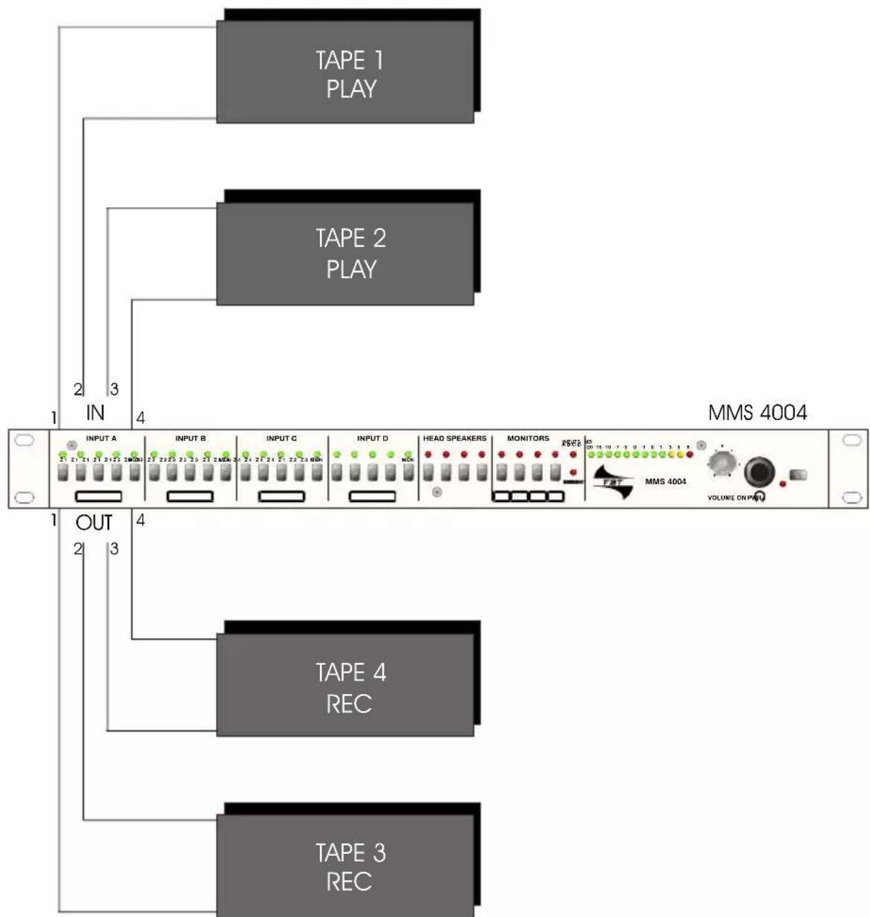
flowchart
graph TD
    A["TAPE 1 PLAY"] --> B["INPUT A"]
    C["TAPE 2 PLAY"] --> D["INPUT B"]
    E["TAPE 3 REC"] --> F["TAPE 4 REC"]
    G["TAPE 4 REC"] --> H["HEAD SPEAKERS"]
    I["MMS 4004"] --> J["MONITORS"]
    K["VOLUME ON INPUT"] --> L["MMS 4004"]
    style A fill:#999
    style C fill:#999
    style E fill:#999
    style G fill:#999
    style I fill:#999
    style K fill:#999
    style L fill:#ccc
    style B fill:#ccc
    style D fill:#ccc
    style F fill:#ccc
    style H fill:#ccc
    style J fill:#ccc
    style L fill:#ccc
    style N fill:#ccc
    style O fill:#ccc
    style P fill:#ccc
    style Q fill:#ccc
    style R fill:#ccc
    style S fill:#ccc
    style T fill:#ccc
    style U fill:#ccc
    style V fill:#ccc
    style W fill:#ccc
    style X fill:#ccc
    style Y fill:#ccc
    style Z fill:#ccc
flowchart
graph TD
    A[" Speakers Line"] --> B[" Zone8 "]
    B --> C[" Line"]
    C --> D[" Music "]
    C --> E[" CALL "]
    D --> F[" ALL CALL "]
    E --> F
    F --> G[" Music "]
    F --> H[" CALL "]
    G --> I[" Remote CALL "]
    H --> J[" Remote CALL "]
    I --> K[" Line COM"]
    J --> L[" Line COM"]
    K --> M[" Line COM"]
    L --> N[" Line COM"]
    M --> O[" Line COM"]
    N --> P[" Line COM"]
    O --> Q[" Line COM"]
    P --> R[" Line COM"]
    Q --> S[" Line COM"]
    R --> T[" Line COM"]
    S --> U[" Line COM"]
    T --> V[" Line COM"]
    U --> W[" Line COM"]
    V --> X[" Line COM"]
    W --> Y[" Line COM"]
    X --> Z[" Line COM"]
    Y --> AA[" Line COM"]
    Z --> AB[" Line COM"]
    AA --> AC[" Line COM"]
    AB --> AD[" Line COM"]
    AC --> AE[" Line COM"]
    AD --> AF[" Line COM"]
    AE --> AG[" Line COM"]
    AF --> AH[" Line COM"]
    AG --> AI[" Line COM"]
    AH --> AJ[" Line COM"]
    AI --> AK[" Line COM"]
    AJ --> AL[" Line COM"]
    AK --> AM[" Line COM"]
    AL --> AN[" Line COM"]
    AM --> AO[" Line COM"]
    AN --> AP[" Line COM"]
    AO --> AQ[" Line COM"]
    AP --> AR[" Line COM"]
    AQ --> AS[" Line COM"]
    AR --> AT[" Line COM"]
MMS 4004
| CARATTERISTICHE CHARACTERISTICS | matricematrix |
| INGRESSI INPUTS | n. 4 a morsettiera bilanciatin. 4 balanced inputs on terminal strip |
| USCITE OUTPUTS | n. 4 a morsettiera bilanciaten. 4 balanced outputs on terminal strip |
| MASSIMO SEGNALE INGRESSO / Z MAX INPUT SIGNAL / Z | 22 dBu bilanciato / 10 kOhm22 dBu balanced / 10 kOhm |
| MASSIMO SEGNALE DI USCITA / Z MAX. OUTPUT SIGNAL / Z | 28 dBu bilanciato / 600 Ohm28 dBu balanced / 600 Ohm |
| USCITA MONITOR OUTPUT MONITOR | presa jack stereo 6.3mm per cuffia / morsettiera per altoparlante stereo jack socket 6.3mm for headphones / loudspeaker socket |
| EMERGENZA EMERGENCY | morsettiera per attivazione circuito emergenzaterminal strip for emergency circuit activation |
| CONTROLLI CONTROLS | -assegnazione di ogni ingresso su ciascuna uscita delle 4 zone-preascolto per ogni ingresso-monitor sulle 4 zone-tasti esclusione linea dedicata speaker-tasto power on-off-regolazione livello monitor-input assignment on each zone-monitor for each input-monitor for each output-headspeaker line exclusion-on-off push button-monitor level control |
| ALIMENTAZIONE POWER SUPPLY | 230 Vac con alimentatore esterno / 120 Vac con alimentatore esterno230 Vac with external power supply / 120 Vac with external power supply |
| INDICAZIONI LUMINOSE LED INDICATION | segnalazione uscita selezionatamonitor emergenza/monitor out per ogni uscitaVU meterpower on-offled indicating output choice for each inputmonitor activated/emergency/monitor output/led indicator for each outputVU meteron-off push button |
| INSERT INSERT | presa jack stereo 6.3mm su ciascuna uscita stereo jack 6.3mm socket on each output |
MZU 2008
BALANCED and UNBALANCED
A connection is balanced when the signal is carried by two conductors (hot and cold) and a screening braid. The hot pin has the job of carrying the in-phase signal, while the cold one carries the same signal, but out of phase. This method enables to make transmitted signals immune to electromagnetic interference even over long lines, thanks to the fact that when the two signals reach the receiving device, they are algebraically subtracted one from the other, producing a new signal with twicw the amplitude and eliminating the interference along its path.
IMPEDANCE (Z)
Represents the resistance offered to AC by an electric circuit. It is measured in Ohms and as opposed to the resistance, takes into consideration the circuit's inductive components (coils) and capacitive components (condensers). Audio signals' input and output circuits are divided into low impedance (with a Z of less than 5 kOhm, such as microphones and loudspeakers) and high impedance (when Z is more than 10kOhm, as is the case with electronic instruments, CD players and recorders). When connecting different units, it is important to have low impedances in inputs and high impedances (more of 2 kOhm) in outputs.
INSERT
This is an interruption in the circuit of the audio path inside a mixer: allows an audio processing to be inserted before the signal passes on to the following mixing or amplification stages. Dynamic processors, equalizers, etc. are normally connected to this socket.
MIXER
An active electronic circuit able to mix two or more audio signals together. A mixer can also feature audio effects, mixing them with the original signals.
I | UK
NOTE NOTES

I | UKNOTE NOTES


Audio Contractor
All information included in this operating manual have been scrupulously controlled; however FBT is not responsible for eventual mistakes. FBT Elettronica S.p.A. has the right to amend products and specifications without notice.
Brand : FBT
Model : MZU 2008
Category : Uncategorized