ISO140 - Electrical accessory BOSS - Free user manual and instructions
Find the device manual for free ISO140 BOSS in PDF.


| Product Type | Electronic device |
| Brand | Boss |
| Model | ISO140 |
| Dimensions (approx.) | 12 x 8 x 3 cm (4.7 x 3.1 x 1.2 in) |
| Weight (approx.) | 200 g (7 oz) |
| Power Supply | 2 x AAA batteries (not included) |
| Battery Life | Approx. 10 hours continuous use |
| Display | LCD screen |
| Key Functions | On/Off, mode selection, setting adjustment |
| Operating Temperature | 0°C to 40°C (32°F to 104°F) |
| Storage Temperature | -20°C to 60°C (-4°F to 140°F) |
| Material | ABS plastic |
| Cleaning | Wipe with a soft, dry cloth. Do not use solvents. |
| Maintenance | Remove batteries if not used for long periods. |
| Safety Precautions | Do not disassemble. Keep away from heat and water. |
| Spare Parts | Contact Boss customer service for replacement parts. |
| Repairability | Repairs should be performed by qualified personnel. |
| Certifications | CE, RoHS |
| Included Accessories | User manual only |
| Warranty | 1 year limited warranty |
Frequently Asked Questions - ISO140 BOSS
User questions about ISO140 BOSS
0 question about this device. Answer the ones you know or ask your own.
Ask a new question about this device
Download the instructions for your Electrical accessory in PDF format for free! Find your manual ISO140 - BOSS and take your electronic device back in hand. On this page are published all the documents necessary for the use of your device. ISO140 by BOSS.
USER MANUAL ISO140 BOSS
natural_image
Exterior view of a yellow and black utility vehicle driving on a dirt road with greenery in the background (no visible text or symbols)ISO140
USER MANUAL
SMART BATTERY
ISOLATOR

natural_image
Close-up of a black electronic component with a green label and coiled cable, no visible text or symbols.
natural_image
Product photo of red and black electrical cables with metal fittings and screws (no text or symbols visible)BOSS Audio Systems
3451 Lunar Court · Oxnard, CA 93030
www.bossaudio.com
805-751-4853 Customer Service
Tech Support: www.bossaudio.com/support
CE

1121

ENGINEERED
IN THE U.S.A.
Introduction
Congratulations on your purchase, and welcome to BOSS Audio Systems!
This smart battery isolator is designed to connect two batteries (start battery and second battery) in your vehicle (e.g. an ATV, UTV or trailer), and allows both batteries to be charged simultaneously from a power source (e.g. a vehicle alternator) in a parallel circuit.
The isolator can automatically disconnect the second battery from the start battery when the voltage drops to 12.8V, and reconnect both batteries when the voltage increases to at least 13.3V. This prevents drain of the start battery and thus ensures adequate voltage to start your vehicle, and allows you to use the second battery to keep car stereo playing and lights on when the vehicle engine is off.
When both batteries are connected together, the LED on the isolator turns on. When disconnected, the LED turns off, indicating a voltage below 12.8V.
This isolator is designed for use with 12V batteries only.
Package Contents
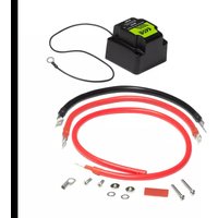
- 1x smart battery isolator with a mounting plate
- 1x red power cable (26"/650 mm, 6 GA) with one lug connector (0.3125"/8 mm)
- 1x red power cable (14"/350 mm, 6 GA) with two lug connectors (0.3125"/8 mm)
- 1x black ground cable (14"/350 mm, 4 GA) with two lug connectors (0.3125"/8 mm)
- 1x lug connector (0.3125"/0.32"/8 mm) and 1x red heat shrink tube (1.5"/38 mm)
- 2x domed head screws (1.5"/38 mm) and 2x flat head screws (0.75"/19 mm)
• 2x terminal nuts and 2x terminal washers - User manual and warranty
Important
Read and understand all instructions before you use your product. If you do not follow the instructions in this manual, we are not responsible for any resulting personal injury or damage to property. This will also void the warranty.
- WARNING: Always consult a professional installer.
- Installation must be performed by a professional. Contact our technical support for any installation question.
- Use only installation parts provided with the product. Using other mounting methods may void the warranty.
- Never operate the product when it is not mounted. Make sure the product is securely mounted and all cables are securely connected to prevent damage, especially in an accident.
- In the event of smoke, strange noise or odor emitted from the product or any other abnormal operational signs appearing on the product, disconnect the product from the power supply. Discontinue use and contact your dealer or our technical support. Using the product in this condition may result in permanent damage to the system.
- Servicing must only be carried out by a technician. Contact our technical support for any service question.
- Observe the safety and operating instructions of any other devices which are connected to the product.
- DO NOT use aggressive cleaning materials on the product.
- DO NOT submerge the product in water.
Specifications
- Input voltage: 12-14V DC
- Cut in/On voltage: 13.3V
- Cut out/Off voltage: 12.8V
- Sensing type: dual battery system
- Charge type: parallel
- Charging current: max 140A
-
Standby current: 10 mA
-
Voltage drop: none
- Status indicator: LED on - cut in; LED off - cut out
- Ingress protection rating: IP65
- Dimensions:
2.68" x 2.68" x 2.17"/ 68 x 68 x 55 mm
• Weight: 1.17 lbs / 530 g
Specifications are subject to change without notice.
Wiring
Important notes on wiring
- See the section "Important" for installation precautions.
- Before wiring, turn off your vehicle engine and disconnect the negative terminal on the start battery and second battery. Connect to 12V batteries only.
- Make sure all cables are securely connected to ensure safety.

Preparation: On the side covers at the bottom of the isolator, locate and select three hole marks out of eight depending on your specific cable routing. Then use a proper cutter tool to break the holes of a proper size through the covers so that three cables connected can be routed out of the isolator housing when mounting.
To prevent ingress of liquids and solid particles through the perforated holes, make sure the holes cut are suitably small and properly sealed.
- Connect your second battery to the isolator.
Using the supplied red cable (14"/350 mm) with two lug connectors, connect the positive terminal on the second battery to the terminal stud marked "SECOND BATT" on the bottom of the isolator. Remember to secure the cable on the stud using a supplied washer and nut.
-
Connect your start battery to the isolator.
-
Using the supplied red cable (26"/650 mm) with a single lug connector, connect it to the terminal stud marked "START BATT" on the bottom of the isolator using the attached lug connector. Remember to secure the cable on the stud using a supplied washer and nut.
- On the unterminated end of the red cable, strip the end to the correct length. Then fasten the stripped portion of the cable to the positive terminal on the start battery.
Depending on your battery terminal type, you may use the supplied separate lug connector and heat shrink tube so that the red cable can be securely fastened to the battery's positive terminal through the connected lug.
- Connect the second battery to the start battery.
Using the supplied black cable, connect the negative terminal on the start battery to the negative terminal on the second battery. Make sure to tighten the ground connection for safety.
- Find the black ground cable which is pre-attached to the bottom of the isolator. Fasten it to the metal frame (chassis) on your vehicle using the attached ring terminal and a suitable screw (not included). Make sure the ground contact point is clean (no paint coated) and the connection is tightened.
- Reconnect the negative terminal on both batteries only when the isolator mounting is completed (see the section "Mounting").
Mounting
Important notes on mounting
- See the section "Important" for installation precautions.
- Use only installation parts provided with the product. Using other mounting methods may void the warranty.
- Before you drill or cut any holes, investigate your vehicle's layout very carefully. Take special care when you work near the fuel tank, fuel lines, hydraulic lines and electrical wiring.
-
Mount the isolator in the location away from extreme heat and fuel lines. Avoid routing cables near any sharp or moving parts.
-
Select a suitable location that is easily accessible and is close to your start battery and second battery.
- Using four screw holes on the supplied mounting plate, mark four mounting holes on the mounting surface.
- Identify two conical holes (countersink) in the diagonal position on the mounting plate. Then correctly orient the mounting plate and fix it on the mounting surface using the conical holes and two supplied flat head screws (0.75"/19 mm).
A means conical holes (countersink); B means cylindrical flat-bottom holes (counterbore). - Correctly orient the isolator and mount it on the fixed mounting plate. Fix the isolator using the cylindrical holes and two supplied domed head screws (1.5"/38 mm).
Frequently Asked Questions
Q: What does LED on or off indicate?
A: When the LED on the isolator is on, both batteries are connected together and therefore are both being charged simultaneously. When the LED is off, both batteries are disconnected and simultaneous charging of both batteries is not possible.
When the battery voltage (start or second battery) increases to at least 13.3V, the isolator is automatically switched on and thus its LED is on. When the battery voltage drops to 12.8V, the isolator is automatically switched off and thus its LED is off.
Q: Is it safe to use a large amperage alternator with this isolator?
A: This isolator handles a max 140A. The alternator must be 140A as maximum output. For reassurance, a 140A circuit breaker or fuse should be used.
Q: How do I solve the issue of the isolator frequently clicking on and off?
A: The frequent cut in and out of the isolator is caused by improper grounding. Make sure the chassis ground point of the isolator is on the clean and bare metal (no paint coated). Simultaneously, check the ground cable connection on the isolator is secure.
- ISO140
- USER MANUAL
- SMART BATTERY
- ISOLATOR
- Introduction
- Package Contents
- Important
- Specifications
- Wiring
- Important notes on wiring
- Mounting
- Important notes on mounting
- Frequently Asked Questions
- Q: What does LED on or off indicate?
- Q: Is it safe to use a large amperage alternator with this isolator?
- Q: How do I solve the issue of the isolator frequently clicking on and off?
Brand : BOSS
Model : ISO140
Category : Electrical accessory