
VFL201A - LCD Screen Ikegami - Free user manual and instructions
Find the device manual for free VFL201A Ikegami in PDF.


| Product Type | Professional Video Monitor |
| Model | VFL201A |
| Brand | Ikegami |
| Display Size | 20 inches (diagonal) |
| Resolution | 1920 x 1080 pixels |
| Dimensions (W x H x D) | 483 x 132 x 450 mm (19 x 5.2 x 17.7 in) |
| Weight | 7 kg (15.4 lbs) |
| Power Supply | AC 100-240V, 50/60 Hz |
| Power Consumption | Approx. 80W |
| Input Connectors | BNC (SDI), HDMI, VGA, Composite, Component |
| Output Connectors | BNC (SDI loop-through) |
| Functions | Waveform, Vectorscope, Color Bars, Blue Only Mode, Marker Display |
| Mounting | 19-inch rack mountable (optional kit) |
| Operation Temperature | 0°C to 40°C |
| Storage Temperature | -20°C to 60°C |
| Accessories Included | Power cord, BNC cables, User manual |
| Safety Standards | CE, FCC compliant |
| Maintenance | Clean with soft dry cloth; avoid liquids |
| Repairability | Contact authorized service center for spare parts |
Frequently Asked Questions - VFL201A Ikegami
User questions about VFL201A Ikegami
0 question about this device. Answer the ones you know or ask your own.
Ask a new question about this device
Download the instructions for your LCD Screen in PDF format for free! Find your manual VFL201A - Ikegami and take your electronic device back in hand. On this page are published all the documents necessary for the use of your device. VFL201A by Ikegami.
USER MANUAL VFL201A Ikegami
Please follow the safety instructions below:
Before you use this unit, be sure to familiarize yourself with this "Safety Precautions" and the "Operation Manual" to use the unit in the proper manner.
After reading these documents, be sure to keep them in a safe place for your reference whenever the information is required.
Concerning Pictographic Symbols
The pictographic symbols contained in this “Safety Precautions” and placed on the units are provided by using various pictographs to ensure that you use this unit in the safe manner and to protect yourself or other persons from any hazards and to prevent any damages occurring from this unit.
The pictographic indications and their meanings are given below. Please thoroughly understand these indications and their meanings before using this unit.
Please understand that there may be some pictographic symbols that may not apply to the unit you purchased.
| Warning | This symbol indicates a content that any erroneous handling of this unit committed by ignoring this symbol may cause an accident resulting in death or serious injury. | |
| Caution | This symbol indicates a content that any erroneous handling of this unit committed by ignoring this symbol may cause an accident resulting in serious injury or in property loss or damage. |
(Note) The symbol indicates a content to call for the user's attention.
Example of Symbols
| The ○ symbol indicates that the action is prohibited. In the diagram or in its vicinity, the concrete contents of prohibition is illustrated. (In the diagrams at left, it is a caution against disassembly of the unit.) | |
| The ● symbol indicated that the action must be carried out in a coercive manner. In the diagram, the concrete content of caution is illustrated (In the diagrams at left, the power plug must be pulled out.) |

Warning
When you use the product:
| Do not place any container containing water or any liquid or small metallic pieces on the unit! Spilt liquid entering inside the unit may cause a fire or an electric shock accident. | |
| Do not use the unit by applying any voltage other than the specified voltage! Application of an unspecified voltage to the unit may cause a fire or an electric shock accident. | |
| Do not allow any metallic or combustible material to enter or be dropped into the unit from an opening! This may cause a fire or an electric shock accident. | |
| Do not make any alterations to this unit! This may cause a fire or an electric shock accident. |
When you install the product:
| Do not install this unit on an unstable position!By doing so, the unit may be dropped or fall down, causing a personal injury. | |
| Do not use the unit by applying any voltage other than the specified voltage!Application of an unspecified voltage to the unit may cause a fire or an electric shock accident. | |
| Be sure to employ a specialized engineering constructor to install the unit in place!This unit must be securely installed in place by using the specified method. Otherwise, it may be dropped or fall down, causing a fire, an electric shock, or a personal injury.If the unit is to be installed on the wall or on the ceiling, he sure to employ a specialized engineering constructor for the work. | |
| Do not make any alterations to this unit!This may cause a fire or an electric shock accident. |
When a trouble has occurred:
| If an abnormal condition should occur, indicated by smoke, strange odor, or noise, be sure to turn off the power switch and unplug the power plug from the outlet!If you keep using the unit as is, a fire or an electric shock accident may occur. Make sure that the smoke has gone out and contact our sales agent or the sales person in charge. | |
| If water or any foreign object has entered inside the unit, turn off the power switch and unplug the power plug from the outlet!If you keep using the unit as is, a fire or an electric shock accident may occur. Contact our sales agent or the sales person in charge. | |
| If the unit is dropped down or its case is broken, turn off the power switch and unplug the power plug from the outlet!If you keep using the unit as is, a fire or an electric shock accident may occur. Contact our sales agent or the sales person in charge. | |
| If this unit should go out of order, turn off the power switch and unplug the power plug from the outlet!If you keep using the unit as is, a fire or an electric shock accident may occur. Contact our sales agent or the sales person in charge. | |
| Do not use any damaged (with the core wire exposed or broken) power cord!If you keep using the unit as is, a fire or an electric shock accident may occur. Contact our sales agent or the sales person in charge. |

Caution
When you use the product:
| [10445] | Do not place any heavy object on this unit!By doing so, the unit may lose the balance and fall down or be dropped down, causing personal injury. |
 | Do not get on or sit on this unit or the carrying case!The unit may be broken or fall down, resulting in personal injury. |
 | Before moving the unit, be sure to turn off the power switch and unplug the power plug from the outlet and disconnect the connecting cables between devices!If you fail to do so, the power cord may be damaged, causing a fire or an electric shock accident. |
| [2307] | If the unit is not to be used for a long time, be sure to unplug the power plug from the outlet for safety.Failure to do so may cause a fire. |
When you install the product:
| Do not block the ventilation holes of this unit! | |
| (ZWS8) | Blocking the ventilation hole may cause heat to build up inside the unit, causing a fire. Do not use the unit in the following manner:Putting the unit upside down; toppling it over sideways; or inverting it.Pushing unit onto a narrow place with poor ventilation.Placing the unit on a soft material such as carpet.Covering the unit with a piece of table cloth, etc. |
To Use the Product Proficiently
When you use the product:
| ·When using the unit at a watery location such as near a bath or poolside, do not allow water to enter this unit or the cables.The water that has entered the unit or the cables may cause an electric accident.Please be especially careful when you use it when it is raining or snowing; near the beach; or in the kitchen. |
| ·If thunder is heard, be sure to use the unit by considering the operating environment and the situation.If required, interrupt the use of the unit, and keep off the unit, or else you may receive an electric shock. |
| ·Do not connect any device to an AC outlet with a power rating (W) exceeding the rating allowed for the outlet.Be sure to check the power rating value indicated near the AC outlet or the Instruction Manual, or the Operation Manual. |
| ·Do not use the power cord or connecting cables by forcefully bending (or twisting or pulling) them.By doing so, the insulation of the cord or cables may be damaged, causing an electric shock accident to occur. |
When you install the product:
| • Install the unit by keeping it away from a location exposed to excessive humidity or dust, oily smoke, or steam.Installation of the unit on such a location may cause an electric shock.Do not place the unit near a cooking table or a humidifier. |
| • Make sure that the unit is securely protected from falling by a sudden earthquake or a shock.Be sure to carry out a falling prevention measure for safety to ensure that no personal injury will occur by falling of this unit. |
Concerning Maintenance of the Product:
| For safety, be sure to turn off the power switch and unplug the power plug from the outlet before carrying out the maintenance of this unit.Failure to do so may cause an electric shock. |
| To ensure that the unit will maintain its performance in a stable manner for a long time, it is recommended that a “Periodic Inspection” should be carried out.Please consult with the sales person in charge for Periodic Inspections. |
| This unit contains some high voltage sections inside. Any inspection, maintenance or repair work of this unit must be carried out by a knowledgeable expert of this type of product, otherwise an electric shock accident may occur. |
Precautions for Use
Read this document carefully and take precautions regarding the following issues to ensure the safe use of this Viewfinder.
- Use of a power supply other than the specified supply (DC) is strictly forbidden.
- Do not apply any shock on the view finder.
Take necessary precautions against shock, as glass materials are used inside OLED / LCD.
- Don't apply strong external force against the screen of the viewfinder.
Don not press the screen strongly. Be careful not to apply strong external force to the screen of the viewfinder.
The screen may be damaged, causing a trouble.
- Avoid using or storing the unit at following locations:
Locations with temperatures outside the specified range
In the open air environment, necessary precautions must be taken against radiation as heat may build up inside the unit by direct sunlight, even if the surrounding temperature may be within the specified range. (Be sure to protect the unit from direct sunlight.)
Make sure that the exhaust and the intake ports on the rear of the Viewfinder is never blocked. Check the exhaust port in particular to confirm that it is not blocked by the black-out curtain and the like.
Rainy, Snowy, and Excessively Humid Locations
May cause an electric leakage or malfunction of the unit.
- Be careful of operation at low temperature
Keep in mind that the function of the backlight will be lower and the life will become short at low temperature. It is recommendable to use the unit at normal temperature.
- Avoid direct sunlight to the screen of the viewfinder
Keep in mind that there is a possibility of spoiling the display performance when the screen of the viewfinder is exposed to the direct sunlight for a long period of time.
Avoid directly touching the surface of the OLED / LCD panel as much as possible. For cleaning the surface, use a piece of dry and soft cloth to wipe off the dirt without harshly rubbing the surface. Do not use any solvent such as thinner or benzene.
- Do not display the same pattern for a long time.
Precautions should be taken as displaying the same pattern for a long time may cause burn-in on the screen.
- Turn off the power when the unit is not used.
- Change the displayed pattern regularly.
-
Turn off the marker when not in use.
-
Precautions against dew condensation
If the unit is used in an environment exposed to sudden temperature changes, dew condensation may occur on the panel surface or inside the unit. Precautions must be taken as operating the unit while condensation is remaining may cause deterioration of the display quality or malfunction of the unit. If dew condensation should occur, do not turn on the power before the dew condensation is eliminated.
9. Do not touch crystalline liquid leaked from the screen of the viewfinder.
When the screen of the viewfinder is accidentally broken and the liquid (crystalline liquid) leaks, do not touch it with your mouth, do not inhale or do not get it to your skin.
If the crystalline liquid gets in your eye or mouth, rinse it immediately with water. If your skin or clothes are stained with it, wipe off with alcohol etc. immediately and wash in cold water with soap.
If left stained, your skin or clothes may be damaged.
If it gets in your eye or mouth, rinse it immediately with water and receive medical treatment from a doctor.
10. Avoid use or storage of the unit in a corrosive gas environment.
Use or storage of this product at a location or the vicinity here corrosive gas including sulfur dioxide, hydrogen sulfide gas, or ammonia gas is generated will not only significantly reduce the service life of the product but also may cause malfunction or an electric leakage. Also, avoid using the unit in an environment exposed to the strong salt winds.
11. When storing the viewfinder for a long period of time, do so in a cool, dark place at constant temperature and humidity.
12. Do not disassembly and remodel.
Do not disassemble and remodel the viewfinder, otherwise causing a trouble or damage.
13. Do not use this product for a space apparatus, a nuclear energy controlling device, or a medical instrument involved with human life.
Concerning the Quality of the OLED / LCD Panel
An extremely high precision technology is used to produce the OLED / LCD panel built in this product, providing 99.99% or higher effective pixels. Please understand, however, that there may be missing pixels or always illuminating pixels at a rate of 0.01% or lower.
Warranty
In case the product should malfunction in the course of normal operations within one year from the date of delivery, the product will be repaired free of charge. However, any repair for the following cases has to be paid even within the warranty period:
-
Any malfunction or damage that has occurred due to one of the following causes:
-
An improper use
- A repair or an alteration carried out by the customer
- Transportation, movement, or falling that has occurred after purchase of the product
-
An external factor including an extraordinary natural phenomenon or application of abnormal voltages
-
Aged deterioration of OLED /LCD panel (Including changes in brightness; increases of light spots or unlit defects, etc.)
-
Damage, discoloration, or deterioration of the housing including the front surface of the panel
If it seems that the product is malfunctioning even after performing daily adjustments, indicated by a phenomenon such as no image available, please contact our sales agent or TECHNO IKEGAMI Co., Ltd.
Notice for Burning of the LCD Panel
This viewfinder employs a high-resolution QHD LCD Panel with 960x540 pixels, and it is possible to burn the LCD panel due to focused strong light, such as sunlight, through the eye-piece.
Please do not turn the eye-piece of the viewfinder toward the sun.
Pay attention the direction of the eye-piece relative to the sun, when not looking into the eye-piece for a period of time.
- If the LCD panel gets burned
Please contact your Ikegami service agency.
* You are liable for the cost of repair.
• The Images of Burned LCD panel
If the LCD panel gets burned due to focused sunlight, it may look like the images below (where circled in red).

natural_image
Simple grayscale image showing a faint oval shape against a dark background, no text or symbols present.
natural_image
Grid pattern with black and white rectangular blocks and a small oval shape in the bottom-right corner (no text or symbols)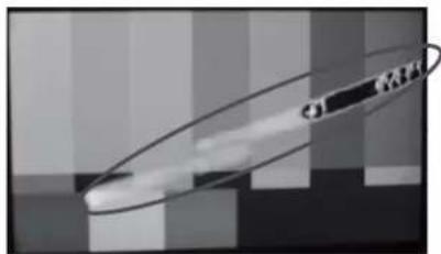
natural_image
Abstract grayscale image with curved lines and a small circular symbol, no readable text or symbols present.
natural_image
Black-and-white coastal scene with wooden boardwalk and rocky shoreline, no visible text or symbolsPreface
●Accessories
The following accessories are available for the product. Check each item:
• Operation manual (1)
- Mounting bracket (1)
Options
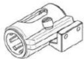
The following Options are available for the product. The "Offset hardware", by which you can adjust the position of mic holder, is supplied for each mic holder.
Mic holder Mic holder Mic holder
Type No.:XM-164
(small antivibration ∅21)
Type :XM-174A No.
(large antivibration ∅19\~21)
Type :XM-254 No.
(large ∅19\~26.5)


●How to Read the Operation Manual
This page explains general notes on reading the VFL201A Operation Manual, and the symbols and notations used in the manual.
Notes on the Manual
- This manual is written for readers with a basic knowledge of handing broadcast cameras.
- The contents of this manual are subject to change without notice in the future.
Symbols
The meanings of the symbols used in this manual are as follows:
| CAUTION: | Things you have to be careful during operation. Be sure to read. |
| Note: | Supplementary information or guidance. |
| Term: | Explains the meaning of a term you need to know. |
Notations
This following notations are used in this manual
This product, viewfinder, VF Indicates VFL201A
Illustrations and Displays
The illustrations and displays in the text are provided for explanation and may be slightly different from the actual equipment or image.
HDTV Analog I/F LCD Color Viewfinder
Table of Contents
Safety Precautions ...... i
Precautions for Use ...... ii
Preface ...... v
- Outline ......E-1
1-1. Outline E-1
1-2. Features and Functions E-1
- Names and Functions ...... E-2
2-1. Front side E-2
2-2. Back side E-3
2-3. Escutcheon E-3
2-4. Mounting/Removing VFL201A to/from the Mount Attachment for UNICAM XE series cameras .... E-4
2-5. Installation of microphone holder ....E-4
2-6. Detaching and installation of eyepiece ...... E-5
- Menu Operation ...... E-6
-
Function switch E-24
-
Specifications E-25
5-1. General specifications ......E-25
5-2. Ratesperformance ..... E-25
5-3. LCD module specifications .....E-26
- Functions ......E-27
6-1. Front operations ......E-27
6-2. Marker function E-27
6-3. Shadow function E-27
6-4. User marker function E-28
6-5. Video MAG function ......E-28
6-6. Peaking function E-28
6-7. Touch sensor function E-28
6-8. Screen saver function ......E-28
6-9. Screen OFF function E-28
- Applicable Standards ......E-29
7-1. Radio noise E-29
7-2. Environmental standards ......E-29
- Exterior Drawing.....JE-30
1. Outline
1-1. Outline
VFL201A is a 2-inch LCD viewfinder developed for HDTV. It has a high resolution QHD LCD with 960 (H) X 540 (V) pixels. It is possible for users to confirm high resolution video with the full color.
It has been developed as a successor to the VFL200HD which had been used for our UNICAM HD camera series. By improving its functions and operation, it achieves the performance required for a viewfinder for broadcast cameras.
1-2. Features and Functions
The LCD with the heater is used
A transparent heater is installed right under the liquid crystal layer. The ambient temperature can be detected and the image without deterioration due to the low response speed at the low temperature can be observed.
Full-color display of 16.7 million colors
16.7 million colors (8bits color) are achieved by a full-color display and a high definition image is supplied.
Abundant peaking features
This viewfinder supplies the abundant peaking features, "ZOOM UP PEAKING" which is synchronized with the camera zoom operation and "COLOR PEAKING" which can add the color on the peak signal, which support the good adjustment of focus.
Abundant markers with shadow
In addition to the area marker, center marker, shadow feature and cross hatch marker, there are 6 (maximum) user markers for each scene, on which users can set them freely. And also, 5 this kinds of scenes are prepared.
Image magnification display feature
This viewfinder can display the magnified image and support the accurate focusing.
Touch sensor function
It detects as soon as a FUNCTION switch is touched, and it displays the function name of the touched switch on the screen. (Patent pending)
2. Names and Functions
2-1. Front side

No. NAME FUNCTION
| 1 | PEAKING VR | The edge amount of peaking for the image is adjusted. |
| 2 | CONTRAST VR | The contrast of the image is adjusted. |
| 3 | BRIGHT VR The brightness of the image is adjusted. | |
| 4 | FUNCTION F1 | This switch can change the setting of a function, which is assigned on the MENU. The default function is “USRMRK”. |
| 5 | FUNCTION F2 | This switch can change the setting of a function, which is assigned on the MENU. The default function is “TALLY”. |
| 6 | FUNCTION F3 | This switch can change the setting of a function, which is assigned on the MENU. The default function is “MONO”. |
| 7 | Mike holder fixation hole | It is a screw hole to install the mike holder. |
| 8 | Diopter movement lever | It is a lever for the diopter movement. |
| 9 | Eyepiece positioning ring | When the back and forth adjustment for the position of the eye cup is needed, this ring is turned. |
| 10 | Eyepiece detaching lever | When the eye cup is detached from VF, this lever is pushed. |
| 11 | Front Tally lamp | This will be turned on by the control signal from the camera. Turning on can be prohibited by MENU. |
| 12 | Menu switch | This is used for setting the items of MENU. |
| 13 | Protection bar | Some front switches and volumes are protected from the external impact. |
2-2. Back side

| No. NAME FUNCTION | ||
| 1 | VF cable The VF cable for | UNICAM HD series cameras. |
| 2 | Rear tally with a cover | This tally will be turned on by the control signal from the camera. The turning on of this tally can't be prohibited. A cover can cut off the light of this tally, if needed. |
| 3 | Attachment for camera | This is the mounting hardware in order to install the VFL201A on the camera. |
| 4 | Eyepiece | This is an eyepiece to observe the VF image. Also, it has the dioptric lens feature. |
2-3. Escutcheon

| No. NAME FUNCTION | ||
| 1 | G TALLY | It receives a G tally signal from the camera, and the green LED lights up. |
| 2 | R TALLY (TOP) | It receives a R tally signal from the camera, and the red LED lights up. |
| 3 | BATT LED | It receives a battery warning signal from the camera, and the orange LED lights up. |
| 4 | [ ! ] LED | It receives a control signal from the camera, and the orange LED lights up.Refer to the instruction manual of the camera for the setting procedure and other details.In addition, while the screen saver or the screen OFF function is on, this LED blinks. |
| 5 | R TALLY (BOTTOM) | It receives a R tally signal from the camera, and the red LED lights up. |
| 6 | EXT LED | While the lens extender is in use, the orange LED lights up. |
2-4. Mounting/Removing the VFL201A to/from the Mount Attachment for UNICAM HD series cameras ■Mounting the VFL201A to the Mount Attachment
This section explains how to mount the VFL201A to the VF mounting attachment of the HDK-99. (The mounting method is the same for other cameras.)
CAUTION:
At first, please confirm whether the mounting hardware for VF is installed in the camera. If there is no mounting hardware in the camera, you can't install this VF.
1 The slide guide of VF is aligned with V shape edge of the mounting hardware for VF in the camera. And VF is mounted on the camera by sliding it while pushing the pin for blocking the VF falling out in.
CAUTION:
Please put the camera on a stable place and install VF to the camera.
2 Please turn VF fixing knob on the mounting hardware in the camera clockwise and fix VF firmly.
MEMO:
Please operate positioning in the horizontal direction of VF after loosening the VF fixing knob.
3 The VF connector is connected with the VF connector of the camera.
CAUTION:
Please pay attention to the direction of the connector.

■Removing VFL201A from the Mount Attachment
This section explains how to remove the VFL201A from the Mount Attachment.
Please remove the VF by the reverse procedure comparing with the mounting one.
CAUTION:
Please put the camera on a stable place and remove VF from the camera.
2-5. Installation of microphone (mike) holder
■The mike holder installation
This section explains the method of mounting the mike holder in VFL201A
At first, the off-set metal plate is fixed at the installation part of mike holder by the special screw.
The mike holder is installed at the installation part of the off-set metal plate by the special screw which is attached with the mike holder
CAUTION:
Please pay attention not to lose the above special screw after removing the mike holder.
2-6. Detaching and installation of eyepiece
■The eyepiece detaching
The detaching lever in the root of the VF eyepiece is pushed, the eyepiece is turned anti-clockwise and it will be detached.
CAUTION:
Please take care that dust doesn't enter VF inside after detaching it.
■The eyepiece installation
Please align the mountain sign displayed in the root of the VF eyepiece with the mountain sign displayed on the VF side and turn it clockwise while pressing it until you hear it clicks.
3. Menu Operation
flowchart
graph TD
    A["MENU(5/7) (MARKER)"] --> B["1. MARKER ON/OFF ON/OFF setting of display of MARKER"]
    B --> C["→MARKER SELECT Setting of marker type"]
    B --> D["→ASPECT MARKER Setting of aspect marker type"]
    B --> E["→SAFETY MARKER Setting of safety marker in "80% to 100% (on 1% basis)"]
    B --> F["→SHADOW MODE Setting of shadow display mode"]
    B --> G["→SHADOW LEVEL Setting of shadow level"]
    A --> H["MENU(6/7) (USER MARKER)"]
    H --> I["1. USER MARKER ON/OFF setting of display of user marker"]
    I --> J["2. MARKER LEVEL Setting of user marker display level"]
    I --> K["3. SCENE SELECT Setting of five types of scenes"]
    K --> L["→RESET SCENEx Execution of resetting the setting scene display"]
    L --> M["<SCENEx> Display of currently selected scene number"]
    M --> N["MRK1: ON □.... Setting of display/color/execution of user marker 1"]
    M --> O["MRK2: ON □.... Setting of display/color/execution of user marker 2"]
    M --> P["MRK3: ON □.... Setting of display/color/execution of user marker 3"]
    M --> Q["MRK4: ON □.... Setting of display/color/execution of user marker 4"]
    M --> R["MRK5: ON □.... Setting of display/color/execution of user marker 5"]
    M --> S["MRK6: ON □.... Setting of display/color/execution of user marker 6"]
    A --> T["MENU(7/7) (INFORMATION)"]
    T --> U["1. MPU VERSION Display of MPU version"]
    T --> V["2. H/W VERSION Display of hardware version"]
    T --> W["3. WORKING TIME Display of working time"]
    T --> X["4. LOAD FACTORY Execution of initialization to default data at shipping from the factory"]
3-2. How to operate and functional descriptions of menus (VF MENU)
◆ Basic operations of the menu switch
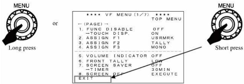
The MENU operation by using MENU switch is explained below.
① Changing MENU pages

flowchart
graph TD
    A["Long press"] --> B["Short press"]
    B --> C{If_the_MENU_switch_is_rotated_when["PAGE"] is displayed in red, the page will change as shown in the diagrams.}
    C --> D["When the MENU switch is press for long, the MENU screen will be displayed. The last MENU page when settings were made in a previous session will be displayed. The initial MENU page displayed immediately after the power is turned ON will be PAGE (1/7)."]
    D --> E["When [PAGE"] is magenta color and the Menu switch is pressed, the["PAGE"] characters will change to red, indicating that the PAGE change mode is enabled.]
② Setting the MENU
When characters of (PAGE) are displayed in red after the MENU screen display has started, pressing the MENU switch will cause the color of (PAGE) to turn to magenta. This indicates that the setting mode within the page is enabled, permitting changes to be made.

flowchart
graph TD
    A["MENU"] --> B["1. FUNC DISABLE OFF"]
    B --> C["2. ASSIGN F1 USRMRK"]
    C --> D["3. ASSIGN F2 TALLY"]
    D --> E["4. ASSIGN F3 MONO"]
    E --> F["5. VOLUME INDICATOR OFF"]
    F --> G["6. FRONT TALLY LOW"]
    G --> H["7. SCREEN SAVER OFF"]
    H --> I["→TIMER 30MIN"]
    I --> J["8. SCREEN OFF EXECUTE EXIT"]

    K["MENU"] --> L["1. FUNC DISABLE OFF"]
    L --> M["2. ASSIGN F1 USRMRK"]
    M --> N["3. ASSIGN F2 TALLY"]
    N --> O["4. ASSIGN F3 MONO"]
    O --> P["5. VOLUME INDICATOR OFF"]
    P --> Q["6. FRONT TALLY LOW"]
    Q --> R["7. SCREEN SAVER OFF"]
    R --> S["→TIMER 30MIN"]
    S --> T["8. SCREEN OFF EXECUTE EXIT"]

    U["MENU"] --> V["By rotating the MENU switch, any item in the page can be selected."]
    V --> W["By pressing the MENU switch, the columns at the right side can be selected. By rotating the MENU switch, changing settings will become possible."]
③ Turning OFF the MENU screen
To erase the MENU, press the MENU switch for long or by press [EXIT] for short.
(*) While a User Marker is being drawn, describing the User Marker can be performed.
(1) VF MENU (1/7) TOP MENU

① FUNC DISABLE
It will disable the FUNCTION switch operation in order to prevent accidental setting changes. It is applicable to all FUNCTION switches from F1 to F3.
In order to disable only a particular FUNCTION switch, leave this setting at "OFF" and select "BLANK" for the setting in Item ③.
The default value is "OFF".
*The FUNCTION switches can be turned ON/OFF by pressing the MENU switch for a couple of seconds, as well as, the operation of this menu setting.
② TOUCH DISPLAY
It turns ON/OFF the display of the function allocated to each FUNCTION switch on the screen when a corresponding FUNCTION switch is touched.
The default value is "ON".
*When "BLANK" is allocated to the FUNCTION switch, nothing is displayed on the screen even with this setting "ON."
③ ASSIGN F1\~F3
Sets up the various functions to be assigned to Function Switches F1 to F3.
◆Items that can be set up:
- USRMRK:ON/OFF switchover of USER MARKER display
• TALLY: OFF/LOW/HIGH setting of Front Tally
- SCR OFF: SCREEN OFF function (Long press)
• SCENE: Switchover of individual scenes of user marker
- REVERSE: Switches ON/OFF of the video inverting display function
- PRESET: Sets a preset value to CONTRAST and BRIGHT
- PEAKING: ON/OFF switchover of PEAKING
- PEAK-UP: Switchover of PEAKING magnification
•NOISESUP: Switchover of Coring levels
•MONO: COLOR/MONO switchover of display
• MARKER: ON/OFF switchover of marker
• MAG.: ON/OFF switchover of Video MAG. function
- GAMMA1.4: Switches between a value set at GAMMA SELECT and “GAMMA1.4”
• GAMMA: Switchover of GAMMA setting value
·CPT-DISP: ON/OFF switchover of CAPTURE operation
- CHROMA: COLOR/MONO switchover of display
• CAPTURE: Image capturing operation
• ZM-PEAK: ON/OFF switchover of ZOOM UP PEAKING
• ZEBRA: Switches ON/OFF of ZEBRA
- BLANK: Allocates no function
The default value is as follows.
F1: "USRMRK"
F2: "TALLY"
F3: "MONO"
④ VOLUME INDICATOR
Sets up ON/OFF of the manual volume indicator display and the zoom indicator display.. When adjusting the PEAKING, CONTRAST, or BRIGHT volume at the right of the front on the MANUAL side, the setting level is displayed by the VOLUME INDICATOR on the Display.
It also displays the indicator linked to the zoom position of the camera.
The default value is "OFF".
⑤ FRONT TALLY
Sets up the brightness and OFF for the Front Tally display. The setting can be made for "OFF", "LOW" or "HIGH".
The default value is "OFF".
*Setting [TALLY] on a FUNCTION switch will enable switching the setting to "OFF", "LOW" or "HIGH".
⑥ SCREEN SAVER
The screen can be automatically turned off under the following conditions in order to protect the LCD panel from deterioration: no operation is conducted for a period set in Item ⑦, and there is no change in the input video signal. In this section, this function is set ON/OFF.
After activation, the screen saver function can be cancelled when a switch and/or VR is operated or when the tally is illuminated by the control system. Then the video display restarts. The screen saver function is not cancelled with moving video.
While the screen saver function is working, the [ ! ] LED blinks.
After cancelling the screen saver function, it may take a moment to stabilize the screen brightness.
The default value is "OFF".
⑦ TIMER
⑥When the screen saver is set to ON, it sets the time required to start the screen saver function.
When there is no VF operation and when the same still picture is continuously displayed for the duration set here, the screen automatically turns off.
The set values of the timer are “5MIN”, “10MIN”, “15MIN”, “30MIN”, and “60MIN”.
The default value is "30MIN".
⑧ SCREEN OFF
When the VF is not used for a certain time, the screen can be forcibly turned off in order to protect the LCD panel from deterioration.
The screen OFF is cancelled when a switch and/or VR is operated or when the tally is illuminated by the control system.
While the screen OFF function is working, the [ ! ] LED blinks.
After cancelling the screen OFF function, it may take a while to stabilize the screen brightness.
* When [SCR OFF] is set to a FUNCTION switch, the screen can be turned off by keep pressing the FUNCTION switch for a couple of seconds. The screen OFF is cancelled when a switch and/or VR is operated or when the tally is illuminated by the control system.
(2) MENU (2/7) VF SETTING

① VOLUME PRESET
“CONTRAST” and “BRIGHT” are set on the setting value of ② and ③ respectively as the preset values.
The default value is "OFF".
* Setting [PRESET] on a FUNCTION switch will enable CONTRAST and BRIGHT value.
② CONTRAST
Sets up the Contrast PRESET value.
The setting value is a value between “-10” and “+10”.
The default value is "0".
③ BRIGHT
Sets up the Brightness PRESET value.
The setting value is a value between “-10” and “+10”.
The default value is "0".
④ H POSITION
Sets up the adjustment of the image position for horizontal direction. The setting value is a value between “-10” and “+10”.
The default value is "0".
⑤ V POSITION
Sets up the adjustment of the image position for vertical direction. The setting value is a value between “-10” and “+10”.
The default value is "0".
⑥ REVERSE SCAN
Sets up the Image Reversing Display function (rotation by 180°). The setting value that can be selected is “OFF” or “ON”.
The default value is "OFF".

*Setting [REVERSE] on a FUNCTION switch will enable ON/OFF switchover of Image Reversing Display function.
⑦ COLOR TEMP.
Sets up the COLOR Temperature.
The setting value is "D65" or "PANEL".
When this is set on "D65", the color temperature will be set to 6500K. When on "PANEL", the image quality, whose contrast is prior, will be realized
The default value is "D65". ("D65" means 6500K.)
⑧ RGB/YPbPr
It sets RGB/YPbPr for the input signal.
The default value is "RGB".
(3) VF MENU (3/7) VIDEO SETTING
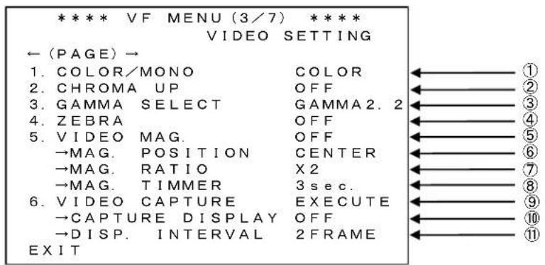
① COLOR/MONO
Sets up the COLOR/MONO display.
The default value is "COLOR".
* Setting [MONO] on a FUNCTION switch will enable ON/OFF switchover of COLOR/MONO.
② CHROMA UP
ON/OFF switchover of CHROMA UP. In ON mode, the color level is increased.
The default value is "OFF".
* Setting [CHROMA] on a FUNCTION switch will enable ON/OFF switchover of CHROMA UP.
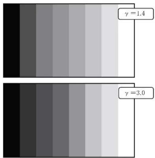
③ GAMMA SELECT
Sets up the Gamma value.
The normal Gamma setting is “2.2” as a standard. This is a function to increase the quality of the gradation in the dark section in images by lowering that Gamma's value to “1.4”, “1.8”, “2.2”, “2.6”, and “3.0”.
The default value is "GAMMA2.2".
* Setting [GAMMA] on a FUNCTION switch will enable GAMMA setting switchover.

By using this function, it becomes possible to support focusing operation while taking a dark scene or when focusing on a dark subject.
④ ZEBRA
It sets ON/OFF of ZEBRA.
The default value is "OFF".
* When [ZEBRA] is set to a FUNCTION switch, the ZEBRA can be switched ON/OFF.
⑤ VIDEO MAG
It sets ON/OFF of the screen magnification.
Video set to MAG. POSITION and MAG. RATIO is displayed on the entire screen, and the image of the entire video area is displayed small at the lower right corner.

The default value is "OFF".
* When [MAG] is set to the FUNCTION switch, the screen magnification function can be switched ON/OFF. (Switching ON/OFF is only available when [MAG] is set to the FUNCTION switch.)
⑥ MAG. POSITION
It sets a position of the screen to be magnified.
The following positions are available for setting.
"CENTER", "TOP", "BOTTOM", "LEFT", "RIGHT", "TOP-L" (TOP LEFT),
"TOP-R"(TOP RIGHT),
"BOTTOM-L"(BOTTOM LEFT).
"BOTTOM-R"(BOTTOM RIGHT)
The default value is "CENTER".

flowchart
graph TD
    A["TOP"] --> B["TOP-R"]
    B --> C["RIGHT"]
    C --> D["BOTTOM-R"]
    D --> E["BOTTOM"]
    E --> F["CENTER"]
    style A fill:#f9f,stroke:#333
    style B fill:#ccf,stroke:#333
    style C fill:#cfc,stroke:#333
    style D fill:#fcc,stroke:#333
    style E fill:#cff,stroke:#333
    style F fill:#ffc,stroke:#333
* Above figure is the figure applicable when MAG. RATIO: "x2".
⑦ MAG. RATIO
It switches the magnification ratio of the screen.
The set values of "x2" (twofold), "x4" (fourfold), and "x8" (eightfold) are available.
The default value is "x2" (twofold).
⑧ MAG. TIMER
Sets up the timer for VIDEO MAG.
The setting is made here for specifying the length of time between the point when the display is turned ON and the point when it is automatically turned OFF.
The setting value is a value between "1sec." and "7sec.", and "OFF".
If OFF is specified, the VIDEO MAG. function will always be set to the ON status.
The default value is "3sec."
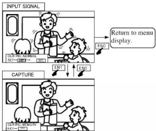
⑨ VIDEO CAPTURE
It captures the input video in the entire screen.
When EXECUTE is executed, the MENU is displayed at the lower left section of the screen. Pressing the ENT switch in this condition captures the entire screen.
When the ESC switch is pressed, it returns to the input signal.
* When [CAPTURE] is set to the FUNCTION switch, the input video is captured in the entire screen.
flowchart
graph TD
    A["INPUT SIGNAL"] --> B["OR PIC: NORMAL SET—ESC"]
    B --> C["ESC"]
    C --> D["Return to menu display."]
    E["CAPTURE"] --> F["ENT"]
    F --> G["ESC"]
    G --> H["Our PIC: MEMORY EXT—ESC"]
⑩ CAPTURE DISPLAY
Sets up ON/OFF of the Screen Capture function.
In the mode set up under item ⑪, ON/OFF switchover of the camera image and the capture image can be performed.
No switchover operation can be performed if the format of the Capture Image and that of the Camera Image differ. Make sure that both images are of the same format for executing switchover operation.
The default value is "OFF".
* When [CPT-DISP] is set to the FUNCTION switch, switching between the video on the camera and the captured image is conducted in the mode set in ⑪.
⑪ DISP. INTERVAL
Sets up the switchover interval between the captured image and the camera image in frame units.
The setting values that can be selected are "1 FRAME", "2 FRAMES", "3 FRAMES", "5 FRAMES", "10 FRAMES", "30 FRAMES", "60 FRAMES", and "HOLD" (manual switchover).
Sets up the number of FRAMES after which switchovers will occur automatically in the case of the "FRAME" mode.
In the "HOLD" mode, manual switching is available with [CPT-DISP] set to the FUNCTION switch.
The default value is "2FRAME".
(4) VF MENU (4/7) PEAKING

① PEAKING
Sets up ON/OFF of PEAKING function.
The default value is "ON".
* Setting [PEAKING] on a FUNCTION switch will enable ON/OFF switchover of PEAKING.
② PEAKING MODE
This sets the directions of the Peaking edge.
“H&V”: The Peaking edges are added to both the horizontal and vertical direction.
"H-ONLY": The Peaking edges are added to the horizontal direction only.
When the setting is “H&V”, the peaking edge flicker may be found in the moving picture. In this case, this phenomenon will be improved by changing the setting to “H-ONLY”.
The default value is "H&V".
③ PEAK WIDTH
Sets up the edge width of Peaking when Peaking is "ON".
The setting value is a value between "1" (thin) and "4" (thick).
The default value is "1".
④ PEAKING UP
When Peaking is "ON", sets up the magnification of the Peaking Level according to the differences in brightness.
By increasing the magnification, it will become easier for peaking to attach to those portions that are difficult for edges to attach because of a small difference in brightness.
In this case, however, peaking will attach even to the noise elements in the image. Therefore, a clear peaking can be realized by using this feature in conjunction with the preceding feature described under ④ NOISE SUP.
The setting values that can be selected are “×1”(OFF), “×2”, “×4”, and “×8”.
The default value is “×1” (OFF).
*Setting [PEAK-UP] on a FUNCTION switch will enable switching of the Peaking Magnification.
⑤ NOISE SUP (NOISE SUPPRESS)
Sets up the Coring Level of Peaking when Peaking is "ON".
This is a function for cutting off the weak edges below the specified threshold value in the edge elements of images. In other words, this function eliminates the edge elements attached to the noise elements in images, allowing a clearer peaking to be realized.
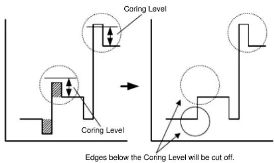
It should be remembered, however, that some weak elements normally attached to the image elements will also be cut off.
The setting value is a value between "0" and "9".
The default value is "5".
* Setting [NOISESUP] on a FUNCTION switch will enable switching of the Coring Level between "0" and "9".
* When the peaking color is set to a color other than "White" in ⑨, the NOISE SUP function does not work. The characteristic becomes the same as the set value "0".
⑥ COLOR PEAKING
The color for peaking can be selected among "White", "Yellow", "Green", "Red", and "Blue".
The default value is "White".
* Functions and characteristic of the peaking color is limited by colors.
- In case the color is "White", the variable peaking amount becomes 128 tones. In case of other colors, it becomes 64 tones. The minimum and maximum values are the same.
- When the color is other than "White", the ④ NOISE SUP function does not work.
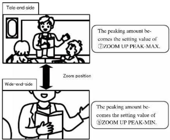
⑦ ZOOM UP PEAKING
When Peaking is "ON", the ON/OFF setting for the function of varying the Peaking amount in conjunction with the zoom position of the camera is carried out here.
flowchart
graph TD
    A["Tele-end-side"] --> B{The peaking amount becomes the setting value of ⑦ZOOM UP PEAK-MAX.}
    B --> C["Zoom position"]
    C --> D["Wide-end-side"]
    D --> E{The peaking amount becomes the setting value of ⑧ZOOM UP PEAK-MIN.}
The default value is "OFF".
*Setting [ZM-PEAK] on a FUNCTION switch will enable ON/OFF switchover of ZOOM UP PEAKING.
⑧ ZOOM UP PEAK-MAX
When ZOOM UP PEAKING is "ON", you can set the value of the peaking amount in the Tele-end side from the setting value in ⑨ to "100".
The default value is "100".
⑨ ZOOM UP PEAK-MIN
When ZOOM UP PEAKING is ON, you can set the value of the peaking amount in Wide-end side from "0" to the setting value in ⑧.
The default value is "0".
(5) VF MENU (5/7) MARKER

① MARKER ON/OFF
Sets up ON/OFF of the Maker Display.
The default value is "OFF".
* Setting [MARKER] on a FUNCTION switch will enable ON/OFF switchover of MARKER.
② MARKER SELECT
Switches over the Marker to be displayed.
The setting values that can be selected are "SAFETY", "CROSS5", "CROSS10", "C.CROSS", "ASPECT", "ASP+SAFE", and "FRM+SAFE".
The default value is "SAFETY".

③ ASPECT MARKER
Switches over the Aspect of the Aspect Marker.
The setting values that can be selected are "4:3", "13:9", "14:9", and "15:9".
The default value is "4:3".

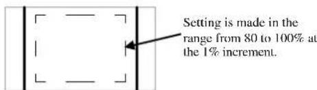
④ SAFETY MARKER
Switches the Safety Area of the Safety Marker.
The setting values that can be selected are between “80%” and “100%” (set at the 1% increment).
The default value is "80%".

⑤ SHADOW MODE
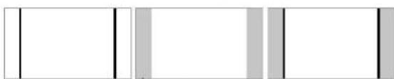
Switches the Display mode of the Aspect Marker.
The setting values that can be selected are "OFF", "SHADOW", and "MRK+SHD".
The default value is "MRK+SHD".
natural_image
Pure geometric lines and rectangles without any text, numbers, or symbolsSHADOWOFF MRK+SHO
⑥ SHADOW LEVEL
Switches the Shadow Level of the Aspect Marker.
The setting values that can be selected are “0%” (black), “20%”, “40%”, and “60%”.
The default value is "60%".
⑦ CENTER MARKER
"OFF", "Type-A" (with center intersection), and "Type-B" (no center intersection) are available for the center marker indication setting.
The default value is "OFF".

natural_image
Three empty rectangular boxes with plus signs in the center, no text or symbols present⑧ MARKER COLOR
Sets up the Marker Color.
The feature is in common with Aspect Marker, Safety Marker, Cross-hatching Marker, and Center Marker.
The setting values that can be selected are "White", "Yellow", "Red", "Blue", "Green", "Cyan", and "Magenta".
The default value is "White".
⑨ MARKER LEVEL
Switches the brightness level of Marker.
The setting values that can be selected are “20%”, “40%”, “60%”, “80%”, and “100%”.
The default value is "100%".
Type B OFF Type A
(6) VF MENU (6/7) USER MARKER

① USER MARKER
Sets up ON/OFF of the USER MARKER display.
The default value is "OFF".
* Setting [USRMRK] on a FUNCTION switch will enable ON/OFF switchover of USER MARKER.
② MARKER LEVEL
Sets up the brightness level of USER MARKER.
The setting values that can be selected are “20%”, “40%”, “60%”, “80%”, and “100%”.
The default value is "40%".
③ SCENE SELECT
Sets up the USER MARKER to be displayed from among SCENE1 through 5.
The default value is "SCENE1".
* Setting [SCENE] on a FUNCTION switch will enable switch-over of individual SCENES of the USER MARKER.
④ RESET SCENE\*
The drawn USER MARKERs are erased by each SCENE.
Select a SCENE to be erased in item ③ first. Then, press the MENU switch at RESET.
At this time, a dialog message asking for a confirmation for erasing is displayed.
At this time, selecting OK and pressing the MENU switch erase the USER MARKER of the SCENE.

The confirmation message

flowchart
graph TD
    A["SCENE1"] --> B["Scene2"]
    B --> C["SCENE3"]
    C --> D["SCENE4"]
    D --> E["SCENE5"]
⑤ MARKER1\~6
In a single scene, 6 types of User Marker can be set for making individual ON/OFF settings, display color settings (for white, yellow, cyan, green, magenta, red, and blue), and the setting for drawing.

flowchart
graph TD
    A["Individual ON/OFF setting"] --> B["Color setting"]
    B --> C["Drawing mode"]
    D["TYPE: **** VF MENU (6/7) **** USER MARKER"] --> E["← (PAGE) →"]
    E --> F["1. USER MARKER"]
    E --> G["2. MARKER LEVEL"]
    E --> H["3. SCENE SELECT"]
    E --> I["→RESET SCENE 1"]
    E --> J["<SCENE 1>"]
    J --> K["MRK1 ON"]
    J --> L["MRK2 ON"]
    J --> M["MRK3 ON"]
    J --> N["MRK4 ON"]
    J --> O["MRK5 ON"]
    J --> P["MRK6 ON"]
    J --> Q["EXIT"]
    R["OFF 40%"] --> S["DRAW-MARKER"]
    R --> T["DRAW-MARKER"]
    R --> U["DRAW-MARKER"]
    R --> V["DRAW-MARKER"]
    R --> W["DRAW-MARKER"]
    R --> X["DRAW-MARKER"]
    R --> Y["DRAW-MARKER"]
    R --> Z["DRAW-MARKER"]
    style A fill:#f9f,stroke:#333
    style B fill:#ccf,stroke:#333
    style C fill:#cfc,stroke:#333
    style D fill:#fcc,stroke:#333
    style E fill:#cff,stroke:#333
    style F fill:#ffc,stroke:#333
    style G fill:#ffc,stroke:#333
    style H fill:#ffc,stroke:#333
    style I fill:#ffc,stroke:#333
    style J fill:#ffc,stroke:#333
    style K fill:#cfc,stroke:#333
    style L fill:#cfc,stroke:#333
    style M fill:#cfc,stroke:#333
    style N fill:#cfc,stroke:#333
    style O fill:#cfc,stroke:#333
    style P fill:#cfc,stroke:#333
    style Q fill:#cfc,stroke:#333
    style R fill:#cfc,stroke:#333
    style S fill:#cfc,stroke:#333
    style T fill:#cfc,stroke:#333
    style U fill:#cfc,stroke:#333
    style V fill:#cfc,stroke:#333
    style W fill:#cfc,stroke:#333
The USER MARKER drawing mode is enabled and drawing actions are performed.
Numbers indicate coordinates of pixels in 960 × 540 . (1,1) (960,1)

- Selection of drawing item and how to draw the USER MARKER
Before start drawing, the drawing item will be selected by turning the MENU switch and you can decide the drawing item by pressing the MENU switch. The value will be selected by turning the MENU switch and that value can be decided by pressing the MENU switch.
Regarding the drawing items, you can change them cyclically like below by turning the MENU switch:
SIZE:H→SIZE:V→POSI:H→POSI:V
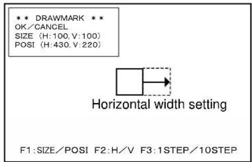
- Drawing for SIZE:H
Horizontal width of a BOX or a LINE can be changed by turning the MENU switch. And also, every time when you click the toggle switch F3, you can change this drawing width unit to 1 or 10 pixels cyclically.
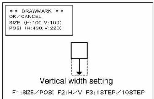
- Drawing for SIZE:V
Vertical width of a BOX or a LINE can be changed by turning the MENU switch. And also, every time when you click the toggle switch F3, you can change this drawing width unit to 1 or 10 pixels cyclically.
(960,540)(1,540)
- Drawing for POSI:H
A BOX or a LINE can be moved in the horizontal direction by turning the MENU switch.
And also, every time when you click the toggle switch F3, you can change the position movement unit to 1 or 10 pixels cyclically.
- Drawing for POSI:V
A BOX or a LINE can be moved in the vertical direction by turning the MENU switch.
And also, ever time when you click the toggle switch F3, you can change the position movement unit to 1 or 10 pixels cyclically.
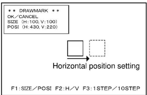

- How to use F1 and F2 toggle switches during the drawing of MARKER
During your drawing MAKER, every time when you click the toggle switch F1 or F2, you can change the drawing item, SIZE and POSI or H and V respectively easily.
F1: SIZE POSI
F2: H V
(7) VF MENU (7/7) INFORMATION
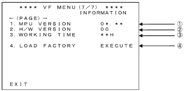
① MPU VERSION
Displays the MPU version.
② H/W VERSION
Display the Hard Ware version
③ WORKING TIME
Displays the accumulated Working Time in which the Viewfinder has been operated in increments of hours.
④ LOAD FACTORY
Returns all settings to the Factory Settings.
4. Switching "Valid/Invalid" operation of the FUNCTION Switches

Long press
◆ “Valid/Invalid” operation of the FUNCTION switches can be switched by holding the MENU switch for a couple of seconds, as well as, by setting with the MENU.
(1) When the MENU is not displayed
When the MENU switch is pressed, the MENU is displayed. Then, if the MENU switch is continuously pressed for two seconds or so, the MENU disappears, and "Valid/Invalid" operation of the FUNCTION switches is possible.
(2) When the MENU is displayed
When the MENU switch is pressed, the MENU disappears. Then, if the MENU switch is continuously pressed for two seconds or so, "Valid/Invalid" operation of the FUNCTION switches is possible.
* When the FUNCTION switch operation is set to "Invalid", the function name is also not displayed by the touch sensor.
5. Specifications
5-1. General specifications
(1) Power-supply voltage
+12 V DC (10.5\~18 V)
(2) Power consumption
4.1 W (+12V DC, Color bar ON (1080i/59.94), Heater OFF, Tally OFF)
(3) Operating ambient temperature/humidity: Storage ambient temperature/humidity
In operation: -20^ +45^
20%\~85% (non-condensing)
For storage: -20^ +60^
20%\~85% (non-condensing)
Maximum wet-bulb temperature: 29°C
(4) Outside dimensions
Main unit: 225 (W) × 76 (H) × 155 (D) mm
(not including protrusions and the mounting bracket)
(5) Mass
780 g or less
(6) Accessories
The mounting bracket (1)
Operation manual (1)
5-2. Rated performance
(1) Camera video signal
a) Input terminal
Input: camera interface 1 system
b) Input signal format (automatic recognition)
1080/60i, 1080/59.94i, 1080/50i, 1080/24PsF, 1080/23.98PsF, 1080/30p, 1080/29.97p, 1080/25p, 1080/24p, 1080/23.98p,
720/60p, 720/59.94p, 720/50p, 720/30p, 720/29.97p, 720/25p, 720/24p, 720/23.98p
c) Input signal
Analog RGB/YPbPr signal
d) Input level
G/Y: 1Vp-p (including SYNC) positive polarity
B/R/Pb/Pr: 700 mVp-p positive polarity
e) Input impedance
75 Ω
5-3. LCD module specifications
(1) Pixels number
960(H) x 540 (V) dot
(2) Pixel pitch
0.0155mm (W) x 0.0465mm (H)
(3) Screen size (display area)
44.64mm x 25.11mm (51.2mm diagonal)
(4) Screen brightness (Only LCD specification)
220cd/m²
(5) Drive method
a-TFT active matrix, non-interlace, normally white
(6) Pixel arrangement
RGB vertical stripe
(7) Response speed
Ton+Toff:16ms(typ.) (Ta=25°C)
(8) Contrast ratio
200:1 (Typ.)
(9) Number of display colors
16.77 million colors (Each of RGB at 8 bits)
(10) Angle of visibility
45^ (up and down, left and right) (contrast ratio 10:1 more)
6. Functions
6-1. Front operations
(1) Menu Switch
Rotary encoder (Moving cursor and enter)
(2) FUNCTION switch (F1 to F3)
Functions can be allocated to the toggle switches from the MENU.
In order to prevent erroneous operation, it is also possible to allocate "BLANK" which allows no operation or to disable the toggle switch operation itself.
(3) Volume
PEAKING, CONTRAST, BRIGHT
6-2. Marker function
(1) Center marker
- Type-A (with a center intersection point)
- Type-B (without a center intersection point)
(2) Safety marker
a) Types
• Safety area marker (80% \~ 100%)
- 5 × 5 division cross-hatch
- 10 × 10 division cross-hatch
• Cross
- Aspect marker (15:9/4:9/13:9/4:3)
- Aspect marker + safety marker
• Frame marker + safety marker
b) Marker level
- Setting in 5 steps of 20% , 40% , 60% , 80% , and 100%
6-3. Shadow function
Function for shadowing outside the aspect marker area
a) Types
- Various aspect markers + shadows
- Various aspect markers only
- Shadows only
b) Shadow contrast level
- Setting in 4 steps of 0% , 20% , 40% , and 60%
6-4. User marker function
Function for the user to draw a box at any location with any size in increments of pixels.
a) Number of scenes: 5
b) Number of types of markers per 1 scene: 6
c) Color: 7 colors (Individual settings allowed)
d) Marker level: 5-step setting in 20%, 40%, 60%, 80%, and 100%
e) Size allowed for drawing: 960 × 540 pixels
f) Drawing method: By using the switch
* Patent registered
6-5. Video-MAG. function
The input images are magnified to x2, x4, and x8. The section to be magnified can be selected from the center, top, bottom, left, right, upper left, upper right, lower left, and lower right. Because of this function, the visibility of pixels improves even in a high-resolution LCD, and confirmation of focusing becomes easier.
6-6. Peaking function
(1) Edge width
The setting value is 1 (thin) \~ 4 (thick).
(2) NOISE SUP
This is a function for cutting off the edges below the specified threshold value in the edge elements of images. In other words, this function eliminates the edge elements attached to the noise elements in images.
(3) PEAKING UP
The amplification of peaking level can be set on x1, x2, x4, and x8 according to the difference of luminance. The peaking will be effect for the pixels whose difference of luminance is low.
(4) ZOOM UP PEAKING
The peaking amount can be variable by being linked with zoom position. The peaking amount will be maximum in tele-end and minimum in tele-wide.
(5) COLOR PEAKING
This function adds the color on the edge of video when the peaking setting is ON. It will be easy to get the fine focusing.
6-7. Touch Sensor Function
When a FUNCTION switch is touched, it immediately detects and displays the function name of the touched switch on the screen. Because of this function, functions allocated to FUNCTION switches and the configuration becomes easy to recognize. Hiding the touch sensor function name is also possible by the menu.
* Patent pending
6-8. Screen Saver Function
When no operation is conducted, or the same image is displayed for a certain period, the screen can be turned off automatically. Because of this function, the screen can be protected from image burn-in, and the lifetime of the LCD can be extended.
6-9. Screen Off Function
With the screen OFF function allocated to a FUNCTION switch, the screen can be turned off if not used for a certain period. Because of this function, the screen can be protected from image burn-in, and the lifetime of the LCD can be extended.
7. Applicable Standards
7-1. Radio noise
·FCC Class-A
·EN55032 Class-A
·EN55103-2 E4
7-2. Environmental standards
Compliant with RoHS Directive
◆Precautions
* Please understand that the specifications and the appearance of this product are subject to changes without notice for improvements.
* Missing or bright spots may occur on this product at a rate of 0.01% or lower. Please understand that this phenomenon is not a malfunction of the product.
□Ikegami Electronics (U.S.A.), Inc.
300 Route 17 South, Mahwah, NJ 07430, U.S.A
Phone: (201) 368-9171, FAX (201) 569-1626
www.lkegami.com
□Ikegami Electronics (Europe) GmbH
Ikegami Strasse 1, D-41460 Neuss, Germany
Phone: 02131-1230, FAX 02131-102820
www.lkegami.de
□Ikegami Electronics (Europe) GmbH (U.K. Branch)
1 Windmill Business Village, Brooklands Close, Sunbury on Thames, TW16 7DY, England
Phone: 01932-769700 FAX 01932-769710
www.lkegami.co.uk
□Ikegami Electronics Asia Pacific Pte.LTD.
1 Tampines Central 5, #3-3 CPF Tampines Building, Singapore 529508
Phone: (+65) 6260-8820 FAX:(+65) 6260-8896
2nd Edition: Aug 2018
Published in Ikegami Factory of Ikegami Tsushinki Co., Ltd.
© July 2018 Ikegami Tsushinki Co., Ltd.
Ikegami
- Please follow the safety instructions below:
- Concerning Pictographic Symbols
- Warning
- Caution
- To Use the Product Proficiently
- Precautions for Use
- Rainy, Snowy, and Excessively Humid Locations
- Do not touch crystalline liquid leaked from the screen of the viewfinder.
- Avoid use or storage of the unit in a corrosive gas environment.
- When storing the viewfinder for a long period of time, do so in a cool, dark place at constant temperature and humidity.
- Do not disassembly and remodel.
- Do not use this product for a space apparatus, a nuclear energy controlling device, or a medical instrument involved with human life.
- Concerning the Quality of the OLED / LCD Panel
- Warranty
- Notice for Burning of the LCD Panel
- Preface
- ●Accessories
- Options
- Mic holder Mic holder Mic holder
- ●How to Read the Operation Manual
- Notes on the Manual
- Symbols
- Notations
- Illustrations and Displays
- HDTV Analog I/F LCD Color Viewfinder
- Table of Contents
- Outline
- 1-1. Outline
- 1-2. Features and Functions
- The LCD with the heater is used
- Full-color display of 16.7 million colors
- Abundant peaking features
- Abundant markers with shadow
- Image magnification display feature
- Touch sensor function
- Names and Functions
- 2-1. Front side
- 2-2. Back side
- 2-3. Escutcheon
- 2-4. Mounting/Removing the VFL201A to/from the Mount Attachment for UNICAM HD series cameras ■Mounting the VFL201A to the Mount Attachment
- CAUTION:
- MEMO:
- ■Removing VFL201A from the Mount Attachment
- 2-5. Installation of microphone (mike) holder
- ■The mike holder installation
- 2-6. Detaching and installation of eyepiece
- ■The eyepiece detaching
- ■The eyepiece installation
- Menu Operation
- 3-2. How to operate and functional descriptions of menus (VF MENU)
- ◆ Basic operations of the menu switch
- ② Setting the MENU
- ③ Turning OFF the MENU screen
- ① FUNC DISABLE
- The default value is "OFF".
- ② TOUCH DISPLAY
- The default value is "ON".
- ③ ASSIGN F1\~F3
- The default value is as follows.
- ④ VOLUME INDICATOR
- ⑤ FRONT TALLY
- ⑥ SCREEN SAVER
- ⑦ TIMER
- ⑧ SCREEN OFF
- ① VOLUME PRESET
- ② CONTRAST
- ③ BRIGHT
- ④ H POSITION
- ⑤ V POSITION
- ⑥ REVERSE SCAN
- ⑦ COLOR TEMP.
- ⑧ RGB/YPbPr
- VF MENU (3/7) VIDEO SETTING
- ① COLOR/MONO
- ② CHROMA UP
- ③ GAMMA SELECT
- ⑩ CAPTURE DISPLAY
- ⑪ DISP. INTERVAL
- VF MENU (4/7) PEAKING
- ① PEAKING
- ② PEAKING MODE
- ③ PEAK WIDTH
- ④ PEAKING UP
- The default value is “×1” (OFF).
- ⑤ NOISE SUP (NOISE SUPPRESS)
- ⑥ COLOR PEAKING
- The default value is "White".
- ⑦ ZOOM UP PEAKING
- ⑧ ZOOM UP PEAK-MAX
- ⑨ ZOOM UP PEAK-MIN
- ① MARKER ON/OFF
- ② MARKER SELECT
- ③ ASPECT MARKER
- ④ SAFETY MARKER
- ⑤ SHADOW MODE
- ① USER MARKER
- ② MARKER LEVEL
- ③ SCENE SELECT
- ④ RESET SCENE\*
- ⑤ MARKER1\~6
- Switching "Valid/Invalid" operation of the FUNCTION Switches
- When the MENU is not displayed
- When the MENU is displayed
- Specifications
- 5-1. General specifications
- Power-supply voltage
- Power consumption
- Operating ambient temperature/humidity: Storage ambient temperature/humidity
- Outside dimensions
- Mass
- Accessories
- 5-2. Rated performance
- Camera video signal
- 5-3. LCD module specifications
- Functions
- 6-1. Front operations
- Menu Switch
- FUNCTION switch (F1 to F3)
- Volume
- 6-2. Marker function
- Center marker
- Safety marker
- 6-3. Shadow function
- 6-4. User marker function
- 6-5. Video-MAG. function
- 6-6. Peaking function
- Edge width
- NOISE SUP
- PEAKING UP
- ZOOM UP PEAKING
- COLOR PEAKING
- 6-7. Touch Sensor Function
- 6-8. Screen Saver Function
- 6-9. Screen Off Function
- Applicable Standards
- 7-1. Radio noise
- 7-2. Environmental standards
- ◆Precautions
- Ikegami
Brand : Ikegami
Model : VFL201A
Category : LCD Screen