
VWA-05 - Wall mount AG Neovo - Free user manual and instructions
Find the device manual for free VWA-05 AG Neovo in PDF.


| Product Type | Wall Mount for Flat Panel Displays |
| Brand | AG Neovo |
| Model | VWA-05 |
| Compatible VESA Patterns | 75x75 mm, 100x100 mm |
| Maximum Load Capacity | 44 lbs (20 kg) |
| Material | Steel with powder coating |
| Color | Black |
| Tilt Angle | 0° to 15° forward tilt |
| Swivel Range | ±90° (left/right) |
| Rotation | 360° (landscape/portrait) |
| Distance from Wall | 1.5 to 2.5 inches (38-64 mm) |
| Installation Type | Fixed to wall studs or concrete |
| Included Hardware | M4, M5, M6 screws and anchors |
| Dimensions (WxHxD) | 6.4 x 9.0 x 1.5 inches (163 x 228 x 38 mm) |
| Weight | 1.5 lbs (0.68 kg) |
| Warranty | Limited 3-year warranty |
| Certifications | TUV, RoHS compliant |
| Maintenance | Wipe with dry cloth; do not use abrasive cleaners |
| Safety Features | Safety cable slot, anti-tip design |
Frequently Asked Questions - VWA-05 AG Neovo
User questions about VWA-05 AG Neovo
0 question about this device. Answer the ones you know or ask your own.
Ask a new question about this device
Download the instructions for your Wall mount in PDF format for free! Find your manual VWA-05 - AG Neovo and take your electronic device back in hand. On this page are published all the documents necessary for the use of your device. VWA-05 by AG Neovo.
USER MANUAL VWA-05 AG Neovo
Physical Dimensions (mm)
VWM-01 VWM-02


Installation

Slide the wallbrackets (2) wit the slot nut in the slot of the aluminium profile (1). Positionate them and sleightly turn on the bolts.
02

VWM-01: Mount the brackets (3) with screw (4 or 5) on the backside of the display. VWM-02: Screw only the screws (4 or 5) in the VESA holes of the display and keep a clearance of 4 mm.

Screw now the brackets with Profile(s) on the wall. Line-up the profile(s) by adjusting the wallbrackets (2). For videowall installation check distance (H + 1 mm) and distance (W-264 mm) and make sure the profiles are levelled (horizontally as well as vertically). To save installation time we suggest to use our additional profile VWA-01.

VWM-01: Hook the display with brackets to the aluminium profile and make sure that adjusting screw (c) does not touch the profile.
VWM-02: Hook the modules to the aluminium profile and make sure that adjusting screw (c) does not touch the profile. Place bolt (a) with associated washer in the sliding nut, but do not tighten. Place the two modules with a horizontal distance according to the width of the VESA.

neovo
VWM-01 / VWM-02 / VWA-01 & VWA-04

natural_image
Two black metal structural components with interlocking beams, displayed against a light blue background (no text or symbols visible)
Installation Manual
Video Wall Mounting Kit
VWM-01 Enclosed Parts

VWM-02 Enclosed Parts

Optional Profiles VWA-01 + Brackets VWA-04
VWA-01 L=2.000 mm


VWA-04

Set-up Guide
Single use
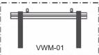
VWM-01:
Installation of single-use or in-line use
Easy installation of Videowall. Push-out function for build-in videowall, easy connecting and service of the displays.
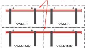
(even lowest line can still be VWM-01)
To install displays straight in one line. For easy and fast in-line or videowall setup.
VWM-02:
OPTIONAL
VWA-01:
In-line use

Videowall use

Installation

Place the screen(s) in the center of the aluminium profile. Adjust vertical positions by slightly turning screw (d) or balance horizontality by adjusting screw (e). if installation is perfect, fix the brackets at the profile by screw (c). For videowall installation keep a clearancy of 1mm between the screens.
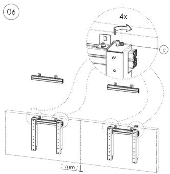

VWM-02: Hook the brackets (6) to the aluminium profile. Place bolt (a) with associated washer in the sliding nut, fix bracket with bolt (c) into the washer through (b) but do not tighten. Place the two brackets (6) with a horizontal distance according to the width of the VESA and push sleightly on the brackets (6) so they push out. Hang the display in the open bracket (6) by glyding the screws (4) or (5) into the key holes.
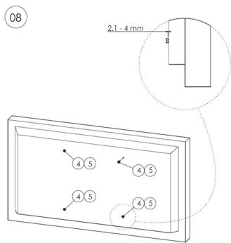

VWM-02: After hanging screen(s) on pushed-out brackets (6) teight-up screws (4) or (5). Keep a distance of 1 mm between 2 screens. Check horizontal positions and fine-tune it by turning screw (e).


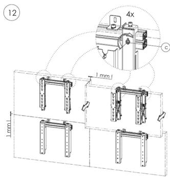
Check virtual position in the push-open and push-closed position and be aware of the 1mm free space when opening and closing the brackets. Push the screen, mounted on a VWM-02, by pressing against the indicated positions until a slight click is heard. The screen is now locked in the closed position. Turn screws (c) to teight-up the mounts.
Hang the remaining screens by repeating the steps 4 until 10. Consider a spacing between the screens of about 1mm.
Replace screen
Press on the screen until a slight click is heard. The screen is now unlocked and will come forward when loosening pressure. Sufficiently loosen the screws (4) or (5) at the rear of the screen, so that the screen can be lifted out of the keyholes.
Remove the screen from the "Push to Open" modules and if needed replace it with a new screen. Tighten the bolts (from Step A) again. Push on the screen until a slight click is heard. The screen is locked in the closed position. If a display on the lowest profile needs service, then only press on the screen above until a slight click is heard. Now release bolt (a) and lift slightly the lower display off the profile.
By using VMW-01 and VMW-02 in a combination, only the defect display needs to be uninstalled.
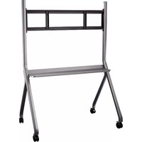
Brand : AG Neovo
Model : VWA-05
Category : Wall mount