Connecting Punch CPPI150 - Audio Amplifier Rockford Fosgate - Free user manual and instructions
Find the device manual for free Connecting Punch CPPI150 Rockford Fosgate in PDF.

User questions about Connecting Punch CPPI150 Rockford Fosgate
0 question about this device. Answer the ones you know or ask your own.
Ask a new question about this device
Download the instructions for your Audio Amplifier in PDF format for free! Find your manual Connecting Punch CPPI150 - Rockford Fosgate and take your electronic device back in hand. On this page are published all the documents necessary for the use of your device. Connecting Punch CPPI150 by Rockford Fosgate.
USER MANUAL Connecting Punch CPPI150 Rockford Fosgate
Output Connection 1 North American Standard Receptacle
Output Voltage Approx. 110 Volts AC RMS 60Hz Output Current 1.36 Amps RMS
Output Waveform Modified Rectangular Wave Input Voltage Range 10.6 to 15.5 Volts DC
Low Voltage Alam Voltage drops below 10.6 Volts DC
Low Voltage Shutdown Voltage drops below 9.6 Volts DC
No Load Input Current 0.3 Amps
Input Fuse 20 Amp AGU
Input Cable Hard Wired Lighter Plug
Additional Protection Overload, Over Voltage, Over Temp
Dimensions Length: 5.6" (142.2mm)
Width: 4.1" (104.1mm)
Height: 1.85" (47.0mm)
Model CPPI300
Output Connection 2 North American Standard Receptacles
Output Voltage Approx. 110 Volts AC RMS 60Hz Output Current 2.73 Amps RMS
Output Waveform Modified Rectangular Wave
Input Voltage Range 10.6 to 15.5 Volts DC
Low Voltage Alarm Voltage drops below 10.6 Volts DC
Low Voltage Shutdown Voltage drops below 9.6 Volts DC
No Load Input Current 0.3 Amps
Input Fuse 40 Amp AGU
Input Cable Lighter Plug and Battery Clip Adapter
Additional Protection Overload, Over Voltage, Over Temp
Dimensions Length: 7.5" (190.5mm)
Width: 4.1" (104.1mm)
Height: 1.85" (47.0mm)
Model
CPPI300HW
Output Connection 2 North American Standard Receptacles
Output Voltage Approx. 110 Volts AC RMS 60Hz
Output Current 2.73 Amps RMS
Output Waveform Modified Rectangular Wave
Input Voltage Range 10.6 to 15.5 Volts DC
Low Voltage Alarm Voltage drops below 10.6 Volts DC
Low Voltage Shutdown Voltage drops below 9.6 Volts DC
No Load Input Current 0.3 Amps
Input Fuse 40 Amp AGU
Input Cable Lighter Plug and Battery
Hard Wire Kit
Additional Protection Overload, Over Voltage, Over Temp
Dimensions Length: 7.5" (190.5mm)
Width: 4.1" (104.1mm)
Height: 1.85" (47.0mm)
WARRANTY INFORMATION
Rockford Fosgate offers a limited warranty with the following terms:
• Length of Warranty
One year parts and labor warranty. Requires proof of purchase.
• What is Covered
This warranty applies only to Rockford Fosgate products sold to consumers by Authorized Rockford Fosgate Dealers in the United States of America or its possessions. Product purchased by consumers from an Authorized Rockford Fosgate Dealer in another country are covered only by that country's Distributor and not by Rockford Fosgate.
• Who is Covered
This warranty covers only the original purchaser of Rockford Fosgate product purchased from an Authorized Rockford Fosgate Dealer in the United States. In order to receive service, the purchaser must provide Rockford Fosgate with a copy of the receipt stating the customer name, dealer name, product purchased and date of purchase.
Products found to be defective during the warranty period will be repaired or replaced (with a product deemed to be equivalent) at Rockford Tosgate's discretion.
• What is Not Covered
-
Damage caused by accident, abuse, improper operations, water, theft
-
Any cost or expense related to the removal or reinstallation of product
-
Service performed by anyone other than Rockford Foggate or an Authorized Rockford Foggate Service Center
-
Any product which has had the serial number detached, altered, or removed
-
Subsequent damage to other components
-
Any product purchased outside the U.S.
-
Any product not purchased from an Authorized Rockford Fosgate Dealer
- Limit on Implied Warranties
Any implied warranties including warranties of fitness for use and merchantability are limited in duration to the period of the express warranty set forth above. Some states do not allow limitations on the length of an implied warranty, so this limitation may not apply. No person is authorized to assume for Rockford Fosgate any other liability in connection with the sale of the product.
• How to Obtain Service
Please call 1-800-669-9899 for Rockford Fosgate Customer Service. You must obtain an RA# (Return Authorization number) to return any product to Rockford Fosgate. You are responsible for shipment of product to Rockford Fosgate. Always include Proof of Purchase. Mark RA# on outside of shipping carton.
Connecting Punch
Rockford Corporation 546 South Rockford Drive
Tempe, AZ 85281 USA
USA, (480) 967-3565
Europe, Fax (49) 4207-8101250
Japan, Fax (81) 559-79-1265
11.02 Printed in China MAN-4437-A
Thank you for purchasing the Rockford Fosgate Connecting Punch Power Inverter.
The Connecting Punch Power Inverters allow you to power a variety of AC voltage devices from your car, truck, boat or RV. Power 110 volt AC power devices such as notebook computers, video game consoles, and TVs directly from a 12 volt DC power supply.
Please read, understand and follow all instructions before connecting the Connecting Punch Power Inverter. If, after reading your manual, you still have questions regarding this product, we recommend that you see your Rockford Fosgate dealer. If you need further assistance, you can call us direct at 1-800-669-9899.
SAFETY INFORMATION

CAUTION:
To prevent injury and damage to the unit, please read and follow the instructions in this manual.

CAUTION:
If you feel unsure about installing this system yourself, have it installed by a qualified technician.

WARNING: To prevent serious personal injury, fire, electrical shock and/or damage, never connect the inverter to an AC powered outlet.
Always unplug the appliance or device from the inverter before attempting any repairs to the appliance or device.
Never connect the inverter to places designated as IGNITION PROTECTED.

CAUTION: Failure to observe the following safety precautions could result in fire, damage to the inverter, vehicle and/or personal injury.
- DO NOT use with 6 or 24 volt DC systems or positive ground electrical systems. The majority of all vehicles are negative ground.
- DO NOT use the inverter to operate high wattage appliances or devices that produce heat, such as hair dryers, healers, toasters, microwave ovens, etc.
• DO NOT operate the inverter if it is wel. - DO NOT install the inverter in the engine compartment. Install in a well ventilated, dry area.
- DO NOT use the inverter with a surge protector or power strip.
- DO NOT use the inverter to power medical equipment or devices.
- DO NOT replace a fuse with one of a different type or rating.
- DO NOT operate the inverter near flammable material or where flammable fumes or gases may accumulate.
• DO NOT connect the inverter to a vehicle battery while it is running. - ALWAYS turn any device connected to the inverter OFF before starting the vehicle.
FEATURES
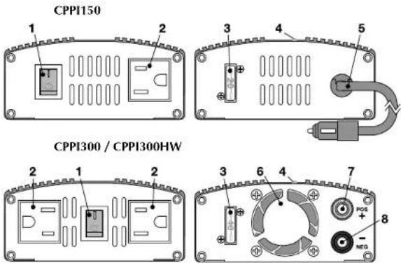
- Lighted On/Off Power Switch – Turns power on and off to AC outlet(s). I=On, O=Off.
- 110 Volt AC Power Outlet(s)
- External Fuse - 20A for CPPI150, 40A for CPPI300 & CPPI300HW.
- LED – Lights green when 12 volt DC power is connected and on.
- Lighter Plug - (CPPI150) Plug into vehicle lighter receptacle.
- High Speed Fan - (CPPI300 & CPPI300HW)
- Positive Binding Post – (CPPI300 & CPPI3001 IW) Connect to positive 12 volt DC power.
- Negative Binding Post - (CPPI300 & CPPI300HW) Connect to negative12 volt DC power.
Locate on your inverter in a well ventilated, dry place free from dirt and grease. Keep the inverter away from heater vents or heat producing devices. If at all possible, keep the inverter away from direct sunlight.
CONNECTIONS
Before connecting the inverter to power, determine the wattage needed to power your devices. Most electrical devices have labels that indicate the power consumption in amps or watts. To convert amps into watts, multiply amps by the voltage. Example: a 110 volt AC device requires 1.2 amps, 110 X 1.2 = 132 watts needed.
If you're plugging the inverter into a cigarette lighter outlet, ensure the outlet can supply the wattage needed. Most vehicles have a 15 or 20 amp fuse protecting the circuit. Multiply the fuse rating by voltage to determine the maximum wattage output available. Example: 12 volts X 15 amp fuse = 180 watts maximum.
NOTE: For loads over 180 watts, connect the inverter directly to the battery.
NOTE: Some vehicles may require you to turn the ignition switch to the On position to supply power to the cigarette lighter outlet.

CAUTION: To prevent fire, damage to the inverter, vehicle and/or personal injury, do not replace a fuse with one of a different type or rating.
NOTE: Some devices, such as TVs and stereos, may require 2 to 6 times their wattage rating to start up. Testing is the only way to check if the inverter will operate these devices. If an overload does occur, the inverter will shut down. Remove the device that caused the overload and if necessary turn the power switch on the inverter Off then On.
Connecting to Cigarette Lighter Outlet (All Models)
- (Models CPPI300 and 300I IW) Connect the cigarette plug harness to the binding posts on the inverter.
- Plug the cigarette plug into the cigarette lighter outlet.
- The green LED on the inverter should light showing power is connected and On.
- Turn the switch on the inverter to On. This will light.
- Plug your device into the inverter and use normally.
Connecting Directly to Battery
(CPPI300 and CPPI300HW Only)
- (Model CPPI300 only) Connect the battery clip harness to the binding posts on the inverter.
- Clip the RED (positive +) clip to the positive (+) post on the battery.
- Clip the BLACK (negative -) clip to the negative (-) post on the battery.

CAUTION: To prevent fire, damage to the inverter, vehicle and/or personal injury, never connect the inverter to a vehicle battery while it is running.
- The green LED on the inverter should light showing power is connected and On.
- Turn the switch on the inverter to On. This will light.
- Plug your device into the inverter and use normally.

CAUTION: To prevent damage to the inverter and/or vehicle, turn any device connected to the inverter OFF before starting the vehicle.