
FV-24CLM - Ceiling fan PANASONIC - Free user manual and instructions
Find the device manual for free FV-24CLM PANASONIC in PDF.


| Product Type | Ceiling Fan |
| Brand | Panasonic |
| Model | FV-24CLM |
| Diameter | 24 inches (610 mm) |
| Height | 8.2 inches (208 mm) |
| Weight | 5.1 lbs (2.3 kg) |
| Motor Type | DC Motor |
| Voltage | 120 V AC, 60 Hz |
| Power Consumption | 28 W |
| Airflow (High Speed) | 3,200 CFM |
| Number of Speeds | 6 |
| Reversible Motor | Yes (Summer/Winter) |
| Remote Control Included | Yes |
| Light Kit Compatible | No |
| Mounting Type | Ceiling Mount |
| Energy Star Certified | Yes |
| Noise Level (High Speed) | 18 dB |
| Material | ABS Plastic Blades, Metal Motor Housing |
| Color | White |
| Safety Features | Overheat Protection, Safety Cable Included |
| Cleaning Instructions | Wipe with dry cloth; do not use water or solvents |
| Warranty | Limited 5 Years |
Frequently Asked Questions - FV-24CLM PANASONIC
User questions about FV-24CLM PANASONIC
0 question about this device. Answer the ones you know or ask your own.
Ask a new question about this device
Download the instructions for your Ceiling fan in PDF format for free! Find your manual FV-24CLM - PANASONIC and take your electronic device back in hand. On this page are published all the documents necessary for the use of your device. FV-24CLM by PANASONIC.
USER MANUAL FV-24CLM PANASONIC
Operating and Installation Instructions
Ventilating Fan
Model No. / No. Model / 型号
FV-17CLM
FV-24CLM

natural_image
3D illustration of a mechanical component with layered surfaces and a cylindrical protrusion (no text or symbols)Operating and Installation Instructions Ventilating Fan
Thank you for purchasing this Panasonic product. Before operating this product, please read the instructions carefully, and save this manual for future use.
Contents
Safety precautions 2-3
Name of parts 7
How to install 8-11
Maintenance Back cover
Specifications Back cover
To avoid the possibility of causing injury to users or damage to properties, please follow all the explanations written below.

This symbol denotes an action that is COMPULSORY.

This symbol denotes an action that is PROHIBITED.

WARNING
A state that may be caused by the mishandling of products, which, if not avoided, may lead to the possibility of death or serious injury of users.

Follow strictly all the instructions given in this manual for installation.
Electrical and installation work need to be performed by a qualified individual.
Installation error may cause fi re, electrical shock, injury or Ventilating Fan to drop.

This appliance is not intended for use by persons (including children) with reduced physical, sensory or mental capabilities, or lack of experience and knowledge, unless they have been given supervision or instruction concerning the use of the appliance by a person responsible for their safety. Children should be supervised to ensure that they do not play with the appliance.

Means for disconnection must be incorporated in the fi xed wiring in accordance with the wiring rules.

Switch off the power supply and wait until the Blades are fully static, before cleaning or doing any maintenance jobs.
May cause injury or electrical shock if Ventilating Fan moves suddenly.
Kindly refer to your authorized dealer for repairing or maintenance.

This product must be properly and reliably grounded.

When this product is no longer be used, it must not be left in place but removed to prevent it from possibly dropping.

Do not switch on or off in case of gas leakage.
May cause fire or explosion due to electric spark.

Do not use power supply other than rated voltage mentioned.
Overheating may cause electrical shock or fire.

Do not disassemble Ventilating Fan unless stated by this manual.
Must use only supplied parts.
May cause fi re, electrical shock, injury or Ventilating Fan to drop.

Do not touch Ventilating Fan while it is operating.
May cause injury, damage or Ventilating Fan to drop.

Do not sprinkle water to Ventilating Fan or do not wet Ventilating Fan.
May cause fi re or electrical shock due to short circuit.

CAUTION
A state that may be caused by the mishandling of products, which, if not avoided, may result in the injury of users or property damage.

To avoid the possibility of causing injury to users or damage to properties, please follow all the explanation written in this manual. The manufacturer will not be responsible for any accidents or injuries caused by defective, defi cient installation or installation which does not follow the instruction manual.

Be sure to provide an appropriate opening for air intake.

Install this product securely.

Make sure that a square inspection hole of at least 45 cm is available.

This Ventilating Fan must be installed by a qualified technician.
May cause injury if Ventilating Fan drops.

Use a device for disconnection from the supply, having a contact separation of at least 3 mm in double poles switch, which must be incorporated in the fixed wiring in accordance with the local electrical wiring rules.

Ventilating Fan must be mounted above 2.5 m from the floor.

This product must be install on to the ceiling which is enough strong, if the ceiling is not enough strong it must be reinforced for it to be strong enough.

This fan should be installed so that the metal parts of the product and mounting screw do not contact any metallic members in the ceiling, such as metal laths, wire laths and metal plate, it is possible to cause fi re harzards in case of leak.

Routine maintenance is required every year. Disconnect the power source before you conduct any maintenance.

If the supply cord is damaged, it must be replaced by the manufacturer or its service agent or a similarly qualified person in order to avoid a hazard.

This product is for in house use only. Can cause rust, discolour, damage or injury.

Do not install this product in places with high temperature.

Do not install this product in places with excessive oil fume.

Do not install this product in places with steam.

Do not form the duct as shown below.


For this fan, precautions must be taken to avoid the back-flow of gases into the room from the open-flue of gas or other fuel-burning appliances.

Do not install the power switch in the bathroom.

Do not install the Ventilating Fan outside of the window or the wall.

Never use petrol, benzene, thinner or any other such chemicals for cleaning the Ventilating Fan.

Do not allow water to contact electrical part such as motors or switches.

Do not immerse blade or other resin parts in hot water over 60 °C.

natural_image
Six identical screwdrivers arranged in two rows, each with a central screw head (no text or symbols)Dimension / Dimensi / 尺寸


| Parts | piece(s) |
| A Fan Body | 1 |
| B Louver | 1 |
| C Tapping Screw | 6 |
| Bahagian-bahagian | unit |
| A Badan Kipas | 1 |
| B Ram | 1 |
| C Skru Tetapan | 6 |
- Do not place Ventilating Fan directly on the floor. It may cause scratches to the product.
Note:
• The illustrations in this manual are for explanation purposes only and may differ from the actual unit.
Perhatian:
1 Identify your ceiling structure and choose one of the methods shown below.
1-A Fan Body Installation (with a wooden keel)
① Remove the caution label a and adhesive tape from the adaptor assembly.
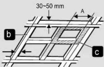
② Build a wooden frame Ⓓ horizontally from the wooden keel ⓑ. Note that the distance between the top of Fan Body Ⓐ and the roof (attic) should be at least 20 mm.
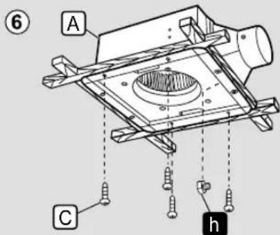
③ Firmly secure Fan Body A with 6 Tapping Screws C.
1-B Fan Body Installation (install the adaptor assembly fi rst)
① First remove the hexagon screw h attaching the adaptor assembly to Fan Body A.
② Remove the adaptor assembly by pushing up ① and pulling to the direction ②. Then peel off the caution label a and adhesive tape from the adaptor assembly.
③ Build a wooden frame c horizontally from the wooden keel b. Note that the distance between the top of the fan body and the ceiling should be at least 20 mm.
④ Attach the adaptor assembly to the wooden frame c as shown in the figure.
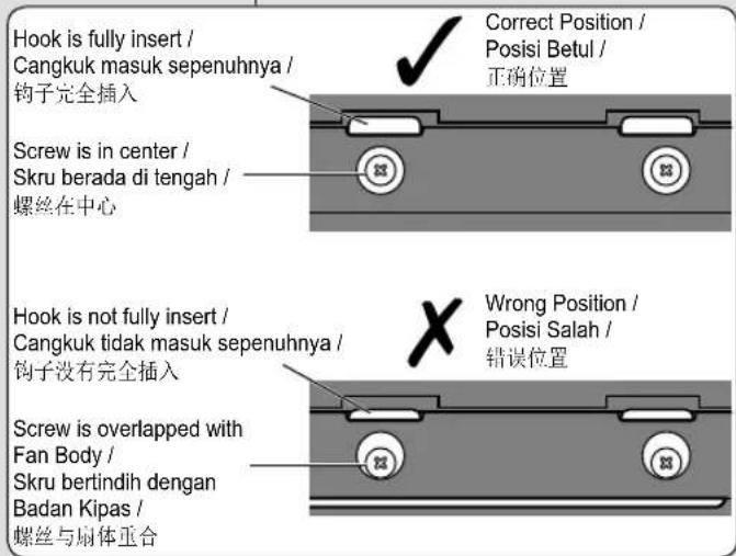
⑤ Insert Fan Body Ⓐ in the wooden frame ⓒ, and connect it to the adaptor assembly.
⑥ Firmly secure Fan Body A with 4 Tapping Screws C and a hexagon screw h.
③
Approximate / Kira-kira / 大约为 30 mm

Hook securely / Disangkut kemas / 钩环保护
FV-17CLM


How to install
Cara pemasangan
如何安装
2 Power Cord Connection.
• Make sure all connections are fastened fi rmly after wiring is fi nished.
- It is required to use terminal (not included) that complies IEC 60998.
- All connections should be accommodated in a suitable compartment.
Sambungan Kord Kuasa.
3 Duct Connection and Ceiling Plate Installation.
① Insert the duct i into the adaptor assembly, and tighten it with adhesive tape (not supplied).
(Suspend the duct i from the ceiling to prevent any external force onto Fan Body A.)
② Install the ceiling plate j. Note that the gap k between the fl ange l and the ceiling plate j should be 2 to 3 mm.
③ Slope the duct i downward and guide it through the wall to the outside. Be sure to prevent rainwater from falling in the duct i from its outlet. (The minimum size of the hole opening on the wall is ∅116 mm)
④ Install the pipe hood or vent cap (optional accessories) on the outer wall.
Note:
- Optional accessories and duct i are not provided by manufacturer.
flowchart
graph LR
    A["①: Raw Material Input"] --> B["②: Internal Component"]
    B --> C["③: Pipe Structure with Wall, Dinding, Wall, Inner側, Slope/Condong/斜度, Outside/Luar/外侧"]
    C --> D["④: Final Packaging with Pipe hood, Vent cap, Penutup, Lubang, and MCX100P, VCX100P"]
How to install
Cara pemasangan
如何安装
4 Test Run and Louver Installation
① When the power is turned on, check for malfunctions as follow:
- Does the fan rotate correctly?
- Does the fan rotate anti-clockwise?
• Is there any abnormal sound or vibration?
② Insert the mounting spring n by pressing the spring and put in direction into the slots m.
Then mount Louver ☐ to Fan Body ☐. (Please wear gloves during installation.)
① Remove Louver B by pressing the spring ① and pull out in direction ②.
Note:
- Do not dismantle Louver Ⓑ into two pieces.
② Rinse Louver B with water and then dry it with a soft dry cloth or leave it air dry. (Do not dry by direct sunlight or heat.)
③ Clean the dirt off Fan Body A with a suction cleaner q.
④ Wipe the dust off Fan Body A with a soft cloth moistened with kitchen detergent, and then clear it with a clean soft cloth. Finally, install Louver B. (Refer Step 4 - ② on page 11.)
■ Nota:


Specifications
Spesifikasi
规格
| Model Model | 型号 | FV-17CLM FV-24CLM | ||
| Voltage (V) Voltan | (V) 电压 (V) 240 240 | |||
| Frequency (Hz) Frekuensi (Hz) 频率 (Hz) 50 50 | ||||
| Power Consumption (W) | Penggunaan Kuasa (W) | 功率 (W) | 13 | 17 |
| Air Delivery (m3/h) | Sebaran Angin (m3/h) | 排气量 (m3/h) | 90 | 160 |
| Noise (dB(A)) | Hingar (dB(A)) | 噪音 (dB(A)) | 29 | 31 |
| Static Pressure (Pa) | Tekanan Statik (Pa) | 静压 (Pa) | 110 | 100 |
| Net Weight (kg) | Berat Bersih(kg) | 净重 (kg) | 2.0 | 3.1 |
Insulation class E IP code:IPX2 Type of Insulation: Functional Insulation Penebat kelas E Kod IP:IPX2 Jenis Penebat: Penebat Berfungsi
E 级绝缘
防水等级:IPX2
绝缘种类:机能绝缘
- Operating and Installation Instructions
- Operating and Installation Instructions Ventilating Fan
- Contents
- WARNING
- CAUTION
- Note:
- Perhatian:
- Identify your ceiling structure and choose one of the methods shown below.
- 1-A Fan Body Installation (with a wooden keel)
- 1-B Fan Body Installation (install the adaptor assembly fi rst)
- FV-17CLM
- How to install
- Cara pemasangan
- 如何安装
- Power Cord Connection.
- Sambungan Kord Kuasa.
- Duct Connection and Ceiling Plate Installation.
- Test Run and Louver Installation
- ■ Nota:
- Specifications
- Spesifikasi
- 规格
Brand : PANASONIC
Model : FV-24CLM
Category : Ceiling fan