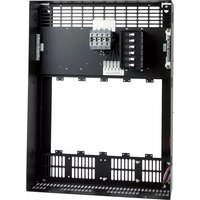
RDA-ENC6B - Electrical enclosure AMX - Free user manual and instructions
Find the device manual for free RDA-ENC6B AMX in PDF.


| Product Type | Enclosure / Rack Mount Chassis |
| Brand | AMX |
| Model | RDA-ENC6B |
| Color | Black |
| Material | Steel |
| Rack Units | 6U |
| Dimensions (H x W x D) | 10.5 in x 19 in x 12 in (267mm x 483mm x 305mm) |
| Weight | 15 lbs (6.8 kg) |
| Power Input | 100-240 VAC, 50/60 Hz |
| Power Consumption | 30W (max) |
| Operating Temperature | 32°F to 104°F (0°C to 40°C) |
| Mounting | 19-inch rack mount with included brackets |
| Compatibility | AMX control systems and modules |
| Certifications | FCC, CE, UL |
| Warranty | 2 years limited |
| Included Accessories | Mounting brackets, screws, power cord, user manual |
| Functions | Enclosure for AMX control processors, amplifiers, or other 6U modules |
| Cooling | Vented front and rear panels for passive airflow |
| Front Panel | Removable front door with lock |
| Rear Panel | Cutouts for cable management |
Frequently Asked Questions - RDA-ENC6B AMX
User questions about RDA-ENC6B AMX
0 question about this device. Answer the ones you know or ask your own.
Ask a new question about this device
Download the instructions for your Electrical enclosure in PDF format for free! Find your manual RDA-ENC6B - AMX and take your electronic device back in hand. On this page are published all the documents necessary for the use of your device. RDA-ENC6B by AMX.
USER MANUAL RDA-ENC6B AMX
The RDA-ENC6B (FG606-13) enclosure provides secure mounting for AMX Lighting and ProLink controllers, and lighting modules. These enclosures contain circuit breakers. They also provide 18 knockouts for 1/2", 3/4", and 1" conduits. They include circuit breakers and terminals for multi-phase wiring.
These enclosures are CE, UL, and C-UL approved.


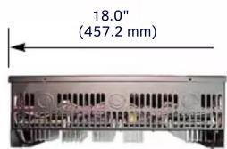
BOTTOM VIEW
RDA-ENC6B Configurations:
- ENC6B/120 20 A Breakers
- ENC6B/240 10 A Breakers
Note:
LINE INPUTS: 120 A MAX PER TERMINAL
Use 75° C copper conductors only.
Torque terminals to 44 in-lbs.
FIG. 1 TOP, FRONT, BOTTOM, AND SIDE VIEWS OF THE RDA-ENC6B ENCLOSURES
Installation Instructions:
- For indoor use only.
- Mount on vertical surface only.
- Maintain 12" (304.88 mm) minimum clearance above and below the enclosure.
- Route class 1 conductors through upper conduit knockouts.
- Route class 2 conductors through lower conduit knockouts.
- Use 75^ C (167°F) copper conductors only.
- Install filler plate #28-10500 (RDA-EFP) in all unused openings.
- Install only UL approved modules (see the UL Number Cross Reference to AMX Lighting ID table).
Enclosure Weights:
• RDA-ENC6B: 16.5 lbs. (7.48 kg)
Dimensions between center lines (from FIG. 2):
RDA-ENC6B:
• A to B = 16.0" (406.4 mm)
• B to C = 22.88" (581.2 mm)
Radia enclosures must be mounted on a vertical surface with a minimum of 12" (304.8 mm) clearance above and below the enclosure.

FIG. 2 BRACKET CONFIGURATION
Specifications
• Maximum input wire #1/0 AWG (50mm ^4 )
• Maximum line input is 120 A (per terminal)
- Torque input wire to 44 in-lbs. (5.0 N/m)
• Wire stripping length: 0.67 inches (17 mm)
- Input 1 feeds channels 1, 4, 7, and 10
- Input 2a feeds channels 5 and 11
- Input 2b feeds channels 2 and 8
- Input 3 feeds channels 3, 6, 9, and 12
- Breakers are UL 489 listed 10,000 AIC, 100% Switching Duty, Hydraulic-Magnetic
The following table cross references the UL ID module numbers and AMX Lighting module IDs. The modules identified are the only ones that can be used in the RDA-ENC6B enclosures.
UL NUMBER CROSS REFERENCE TO AMX LIGHTING ID
| UL ID AMX ID |
| 28-10140 RDD-DM6/120 |
| 28-10150 RDD-DM6/240 |
| 28-10160 RDD-DM6/277 |
| 28-10170 RDA-PSM/120 |
| 28-10200 RDM-INC |
| 28-10210 RDM-2INC |
| 28-10260 RDM-3SWM |
| 28-10350 RDM-2FDB |
| 28-10370 RDM-DC, RDM-2DC, RDM-3DC |
Lighting Application Drawings

SINGLE PHASE. 120VAC. 2W + G CONNECTED PHASE CONTROLS ALL DIMMRS 1-6

SINGLE PHASE. 120/208VAC. 3W + G PHASE B - CONTROLS DIMMERS 1, 4 AND 5 PHASE A - CONTROLS DIMMERS 2, 3, AND 6

THREE PHASE. 120/208VAC. 4W + G
PHASE A = CONTROLS DIMERS 1 AND 4
PHASE B = CONTROLS DIMERS 2 AND 5
PHASE C = CONTROLS DIMERS 3 AND 6
Note:
LINE INPUTS: 120 A MAX PER TERMINAL
Use 75° C copper conductors only.
Torque terminals to 44 in-lbs.
FIG. 3 ENC6B AND ENC12B POWER DISTRIBUTION
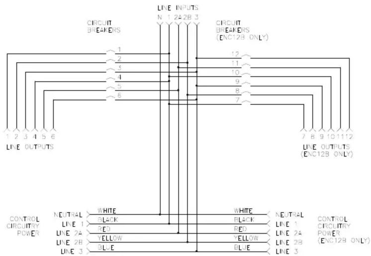
FIG. 4 ENC6B AND ENC12B INPUT TERMINAL BLOCK WIRING
Brand : AMX
Model : RDA-ENC6B
Category : Electrical enclosure