8653 - Lock Lockwood - Free user manual and instructions
Find the device manual for free 8653 Lockwood in PDF.

| Product Type | Mortise Lock |
| Brand | Lockwood |
| Model | 8653 |
| Finish | Polished Brass |
| Backset | 60 mm |
| Faceplate Dimensions | 24 mm x 235 mm |
| Weight | Approximately 1.2 kg |
| Power Source | None (Mechanical) |
| Key Type | Standard Pin Tumbler |
| Number of Keys Supplied | 3 |
| Main Functions | Deadbolt locking and unlocking via key; latch bolt operation via handle |
| Security Rating | Australian Standard AS 4145.2 compliant |
| Installation | Requires standard mortise preparation for 60 mm backset |
| Maintenance | Periodic lubrication with graphite powder; clean exterior with damp cloth |
| Spare Parts Available | Keys, faceplates, strike plates, and internal springs |
| Warranty | 2 years against manufacturing defects |
| Operating Temperature | -10°C to 50°C |
| Material | Brass body with stainless steel bolts |
| Reversibility | Non-handed (field reversible) |
| Compliance | Meets fire safety standards for exit doors |
Frequently Asked Questions - 8653 Lockwood
User questions about 8653 Lockwood
0 question about this device. Answer the ones you know or ask your own.
Ask a new question about this device
Download the instructions for your Lock in PDF format for free! Find your manual 8653 - Lockwood and take your electronic device back in hand. On this page are published all the documents necessary for the use of your device. 8653 by Lockwood.
USER MANUAL 8653 Lockwood

LOCKWOOD 8653 SECURITY
SLIDING 3 POINT DOOR LOCK
Part No. 8653-221 kw.60916
INSTALLATION INSTRUCTIONS
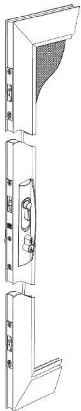
natural_image
Technical line drawing of a three-tiered door frame structure with no visible text or symbols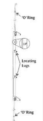
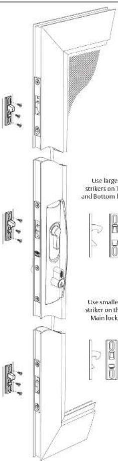
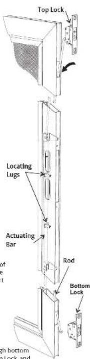
Ensure Actuating bar and Rods are assembled as shown prior to assembly to the door frame. With the 'TOP' mark facing the top of the door.
Keeping the Locating Lugs of the Actuating bar facing the front edge of the stile, insert the rod assembly through the top cut-out, and slide it through the door section. With the Top lock in the locked position, connect the rod and push into place.
Pull bottom rod end through bottom cut-out. Connect to Bottom Lock, and push into place.
1a
Mounting of the Handle below the centreline
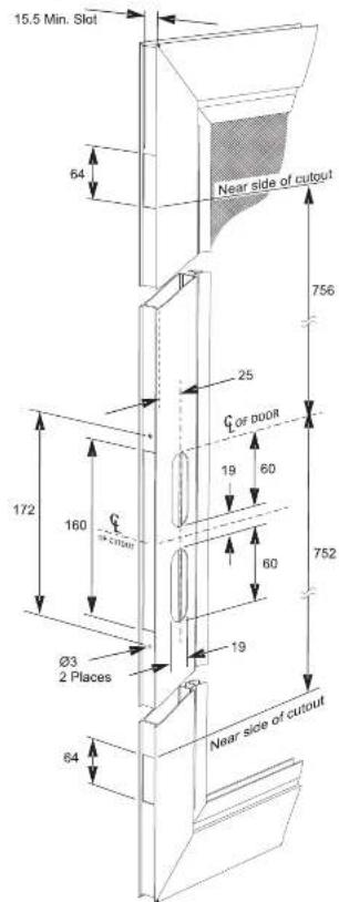
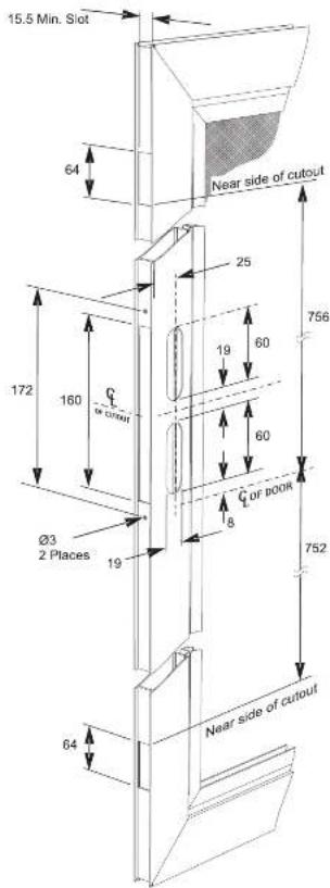
Both sides of the door stile must be cut out to the dimensions given. Start with the centreline of the door.
Both sides of the door stile must be cut out to the dimensions given. Start with the centreline of the door.
1b
Mounting of the Handle above the centreline
2
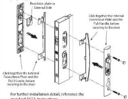
After ascertaining the handling configuration required, simply click the desired handle plates together and install the operating levers and external restrictor plate as required. Then secure the furniture plates to the door section using the two 25mm screws & plugs supplied.

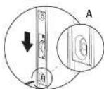
Installation of Top Auxiliary Lock
Step A Ensure the lock is in the Red "Locked" position. Gently push the top lock until it stops.
Drill a ∅3mm hole in the centre of the slot, and loosely fit the first fixing screw.
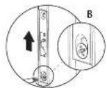
Step B Push the lock towards the top of the door, tighten the first screw.
Check the beak position as per Step 4. Unlock and lock the main lock to check operation.
Ensure the lock is in the Red "Locked" position, drill and fasten the second screw.

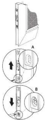
Installation of Bottom Auxiliary Lock
Step A Ensure the lock is in the Red "Locked" position. Gently push the bottom lock until it stops.
Drill a ∅3mm hole in the centre of the slot, and loosely fit the first fixing screw.
Step B Push the lock towards the bottom of the door, tighten the first screw.
Check the beak position as per Step 4. Unlock and lock the main lock to check operation.
Ensure the lock is in the Red "Locked" position, drill and fasten the second screw.

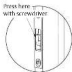
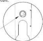
Checking of Top and Bottom Auxiliary Locks
For correct function, the beak should remain secure when pressure is applied in deadlocked state.
To check correct function,
deadlock the door and apply downwards pressure
apply downwards pressure with a screw driver. In position
shown. If the beak releases, the lock is
now out of sync. Re-synchronise the lock and
adjust the lock slightly downwards. Deadlock,
and repeat test until the beak is secure.
Re-synchronising the Lock
If the lock is out of sync and
cannot be operated, rem the furniture claims and
the furniture plates and indicator assembly.
Insert a small flat head screw
driver into the indicator
mechanism as shown. Turn the mechanism in the key locking
direction. Check the operation of the lock.

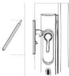
Mounting the Striker
With the strikers inserted in the main lock body, and the top and bottom locks, either mark the position on the outside of the jamb or remove the backing from the tape and allow the strikers to stick to the frame. Remove strikers from locks.
natural_image
Technical line drawing of a door handle and keyhole assembly (no text or symbols)For the main lock drill two ∅3mm holes and fit to door jamb where marked using 12mm countersunk screws.
Adjust striker to correct
position and then tighten
screws. For timber jambs, use longs
jambus, use longer 10g screws provide
Repeat the process
with the top and bottom
strikers using the 8g screws provided.