
Hybrid 1500 - Heating Real Flame - Free user manual and instructions
Find the device manual for free Hybrid 1500 Real Flame in PDF.


| Product Type | Electric Heater with Flame Effect |
| Brand | Real Flame |
| Model | Hybrid 1500 |
| Heating Power | 1500 W (max) |
| Heating Area | Up to 37 m² (400 sq ft) |
| Voltage | 120 V ~ 60 Hz |
| Dimensions (W x H x D) | 76.2 x 45.7 x 20.3 cm (30 x 18 x 8 in) |
| Weight | 15.9 kg (35 lbs) |
| Heat Settings | Low (750 W) / High (1500 W) |
| Flame Modes | 5 flame brightness levels, with or without heat |
| Control Method | Touch panel and remote control |
| Thermostat | Adjustable thermostat (62°F – 82°F) |
| Timer | 1 – 8 hours auto shut-off |
| Safety Features | Overheat protection, tip-over switch, cool-touch glass |
| Installation | Freestanding or wall-mounted |
| Power Cord Length | 1.8 m (6 ft) |
| Maintenance | Wipe with dry cloth; do not use water or abrasives |
| Spare Parts | Replacement flame bulbs, remote control, glass panel |
| Reparability | Consult qualified technician for repairs |
Frequently Asked Questions - Hybrid 1500 Real Flame
User questions about Hybrid 1500 Real Flame
0 question about this device. Answer the ones you know or ask your own.
Ask a new question about this device
Download the instructions for your Heating in PDF format for free! Find your manual Hybrid 1500 - Real Flame and take your electronic device back in hand. On this page are published all the documents necessary for the use of your device. Hybrid 1500 by Real Flame.
USER MANUAL Hybrid 1500 Real Flame
Hybrid fire boxes are approved to be installed as a zero clearance firebox and are designed to operate on Natural Gas and ULPG gases ONLY.
Approval Number: GMK10099
Installed primarily as a decorative appliance. Not certified as a Space Heater.
VERSION 10.2
WARRANTY INFORMATION
The benefits provided to you under the following warranty are in addition to any other rights and remedies available to you under the law.
1. Warranty
If:
(a) during the first 15 years from the date of purchase (Firebox Warranty Period), there is a defect in the firebox of the Gas Burner; or
(b) during the first 2 years from the date of purchase (Parts Warranty Period), there is a defect in the gas valves or other parts of the Gas Burner,
due to improper workmanship or material, Glen Dimplex will replace or repair the Gas Burner without charge. Any replacement product is warranted only for the time remaining on the original Firebox Warranty Period or the Parts Warranty Period as relevant.
2. Registration
You must register to receive the benefit of this warranty by completing the warranty registration on our website (www.realflame.com.au) or completing and mailing the attached registration card within 30 days of purchase of your Gas Burner (or, if the Gas Burner is fitted to a new home, within 30 days of the date of settlement of purchase of such new home).
3. Exclusions
Glen Dimplex is not obliged to replace or repair the Gas Burner under clause 1 if:
(a) it has been improperly stored, installed, connected, used, operated or repaired, or damaged, abused, tampered with, altered (without our written approval), or not maintained in strict accordance with our installation and operating instructions; or
(b) it has been installed in an outdoor setting.
4. Limit of Liability
The warranty provided under this warranty is limited to replacement or repair of the Gas Burner only, at our option. To the extent permitted by law, Glen Dimplex excludes liability for consequential loss or any other loss or damage caused to property or persons arising from any cause whatsoever, and damage arising from normal wear and tear.
5. Claiming under the Warranty
In order to claim under this warranty you must, within the Firebox Warranty Period or the Parts Warranty Period (as relevant), contact Glen Dimplex, providing the original proof of purchase and the details below:
Supplier Name
Date Of Purchase / settlement of property if new home ____
Model / Serial Number
This warranty does not cover the cost of claiming under the warranty or transporting the Gas Burner to and from the supplier.
Our goods come with guarantees that cannot be excluded under the Australian Consumer Law. You are entitled to a replacement or refund for a major failure and for compensation for any other reasonably foreseeable loss or damage. You are also entitled to have the goods repaired or replaced if the goods fail to be of acceptable quality and the failure does not amount to a major failure.
If you would like to speak to someone about your Gas Burner or claiming under this warranty, please contact the Service Warranty Desk on 1300 554 155.
Glen Dimplex Australia Pty Ltd ACN 69 118 275 460
Head Office: 1340 Ferntree Gully Road, Scoresby 3179
Telephone: (03) 8706 2000 Facsimile: (03) 876 2001
INSTALLATION NOTICE
The installation of this appliance is only to be carried out by an authorised person in accordance with the Manufacturer's Instructions, local gas fitting regulations, AS/NZS 5601.1-2013 installation code for gas burning appliances and any other relevant statutory regulations.
In all cases the installation of this appliance shall meet the requirements as set out in AS/NZS 5601.0423.
NOTE: A slight smell may be apparent for the first few hours of use. This is due to the heat resistant paint curing. It is recommended to open windows in the room for the first lighting of the fire. In some instances a slight discolouration may occur inside the firebox. This is a normal condition and is not covered by warranty.
IMPORTANT SAFETY NOTICES
■ DO NOT PLACE ARTICLES ON OR AGAINST THIS APPLIANCE.
■ DO NOT USE OR STORE FLAMMABLE MATERIAL NEAR THE APPLIANCE.
■ DO NOT SPRAY AEROSOLS IN THE VICINITY OF THIS APPLIANCE WHILST IT IS IN OPERATION.
■ CARE MUST BE TAKEN TO ENSURE THAT ANY RETURN AIR REGISTER OR EXHAUST SYSTEM DOES NOT ADVERSLEY AFFECT THE OPERATION OF THE APPLIANCE OR DRAUGHT OF CHIMNEY OR FLUE.
■ DO NOT MODIFY THIS APPLIANCE.
THIS APPLIANCE IS DESIGNED TO OPERATE WITH LUMINOUS FLAMES. THIS MAY EXHIBIT SLIGHT CARBON DEPOSITS.
WARNING
This firebox has a naked flame, care should be taken when it is operating if children or the infirm are in close proximity. A safety screen is recommended if constant supervision is not possible. It is recommended that a secondary guard complying with AS-NZS2286 be installed.
The appliance is not intended for use by persons (including children) with reduced physical, sensory or mental capabilities, or lack of experience and knowledge, unless they have been given supervision or instruction concerning use of the appliance by a person responsible for their safety. Children should be supervised to ensure that they do not play with the appliance.
SERVICING
It is recommended you service your gas fire every 2 years as a minimum.
VENTILATION REQUIREMENTS
| MODEL SIZE EFFECTIVE VENTILATION | |
| HYBRID 1000 50,000mm | 2 |
| HYBRID 1500 72,000mm | 2 |
| HYBRID 1800 72,000mm | 2 |
| HYBRID 3300L 72,000mm | 2 |
| HYBRID 3300R 72,000mm | 2 |
THIS APPLIANCE REQUIRES FRESH AIR TO OPERATE SAFELY. THE ROOM WHERE THIS APPLIANCE IS INSTALLED MUST HAVE PERMANENT VENTILATION FROM OUTDOORS. THIS VENTILATION MUST NOT BE MODIFIED.
NOT INTENDED AS A FIREPLACE INSERT.
CONTENTS
Contents 4
Data Plate 5
Zero Clearance Modular Installation & Dimensions....6
Dimensions Hybrid 1000....7
Dimensions Hybrid 1500....8
Dimensions Hybrid 1800....9
Dimensions Hybrid 3300....10
Zero Clearance Modular Installation
Timber Frame Installation ....11
Installation Check List....12
Lighting/Testing and Failure Procedure 13
Flue Requirements (Standard) 14
Flue Requirements (Power Flue Kit)....15
Optional Power Flue ....16
Introduction....16
Installation ....16
Commissioning....19
Motor Clearance....20
Frameout ....21
Motor 21
Internal Motor 22
External Motor 22
Dimensions....23
Troubleshooting Electronic Ignition and Power Flue System ......25
Wiring Diagram....27
Parts 28
Bases & Fronts 29
Glen Dimplex contact information....32
DATA PLATE (Affixed to the base of the unit for reference to gas pressure & consumption)
Hybrid 1000 & Hybrid Signature 1000
Fitted with Magiglo 750 or 750EI burner
| Gas Injector Size (mm) TPP N.G.C. (Mj/Hr) |
| Natural Gas 3 x 1.90 0.75 kPa 39 |
| ULPG 3 x 0.95 2.55 kPa 34 |
Hybrid 1500 & Hybrid Signature 1500
Fitted with 1000 or 1000EI burner
| Gas Injector Size (mm) TPP N.G.C. (Mj/Hr) |
| Natural Gas 3 x 2.25 0.75 kPa 49 |
| ULPG 3 x 1.12 2.60 kPa 49 |
Fitted with 1200 burner
| Gas Injector Size (mm) TPP N.G.C. (Mj/Hr) |
| Natural Gas 4 x 2.20 0.80 kPa 55 |
| ULPG 4 x 0.95 2.55 kPa 48 |
Hybrid 1800 & Hybrid Signature 1800
Fitted with 1400 or 1400EI burner
| Gas Injector Size (mm) TPP N.G.C. (Mj/Hr) |
| Natural Gas 4 x 2.25 0.85 kPa 60 |
| ULPG 4 x 0.95 2.55 kPa 48 |
Hybrid 3300L & Hybrid 3300R, Hybrid signature 3300L & Hybrid signature 3300R
Fitted with 1400EI burner
| Gas Injector Size (mm) TPP N.G.C. (Mj/Hr) |
| Natural Gas 4 x 2.25 0.85 kPa 60 |
| ULPG 4 x 0.95 2.55 kPa 48 |
ZERO CLEARANCE MODULAR INSTALLATION
- The Firebox is designed to be installed into a new frame out as shown on page 11.
- The fire can be installed at ground level or raised to what ever height is required providing the flue length is 3.6 meters or more.
• The firebox can sit directly onto a wooden surface. - The Firebox requires twin skin flue with an AGA approved cowl (or optional Power Flue – refer pages 15 to 27)
• The control valve on the Firebox is an electronic ignition system and as such, electrical work is required.
Overall Dimensions (in mm)
| MODEL A | B | C | D | E | ||
| 1000 | 920 | 1100 | 450 | 570 | 180 | |
| 1500 | 1000 | 1600 | 450 | 500 | 190 | |
| 1800 | 1140 | 1900 | 450 | 500 | 190 | |
| 3300 L&R Assembled | 1135 | 3400 | 450 | 500 | 190 | |


Right Hand Hybrid shown
Flue Sizes (in mm)
| MODEL Size Inner Outer |
| HYBRID 1000 250 300 |
| HYBRID 1500 300 350 |
| HYBRID 1800 300 350 |
| HYBRID 3300L / 3000R 300 x 2 350 x 2 |
| POWER FLUE (optional) Refer model |
THIS APPLIANCE REQUIRES FRESH AIR TO OPERATE SAFELY. THE ROOM WHERE THIS APPLIANCE IS INSTALLED MUST HAVE PERMANENT VENTILATION FROM OUTDOORS, IN ACCORDANCE WITH THE VENTILATION REQUIREMENTS OF AS/NZS 5601.
DIMENSIONS
Hybrid 1000 - Left Hand Model

| A | B | C | D | E | F | G | H |
| 9201100450570 | 180 | 335230150 | |||||
| I | J | K | L | M | N | O |
| 400120501050520350 | ||||||


Hybrid 1000 - Right Hand Model

DIMENSIONS
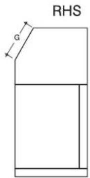
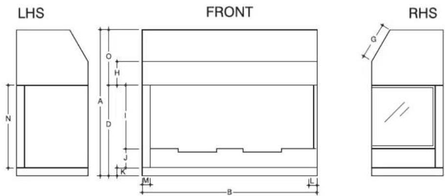
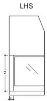
Hybrid 1500 - Left Hand Model
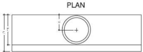
| A | B | C | D | E | F | G | H |
| 10001600450500190370215300 | |||||||
| I | J | K | L | M | N | O |
| 330120501050450500 | ||||||


Hybrid 1500 - Right Hand Model


DIMENSIONS
Hybrid 1800 - Left Hand Model
| A | B | C | D | E | F | G | H |
| 11351900450500190370215435 | |||||||

| IJ | K | L | M | N | O |
| 330120501050450635 | |||||


REAR

Hybrid 1800 - Right Hand Model


DIMENSIONS
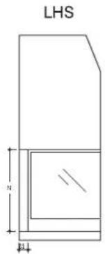
Hybrid 3300 - Left Hand Model
| A | B | C | D | E | F | G | H |
| 11353400450500190370215435 | |||||||
| I | J | K | L | M | N | O |
| 330120501050450635 | ||||||
PLAN

LHS
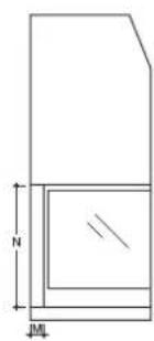
FRONT
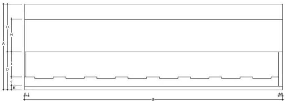
REAR

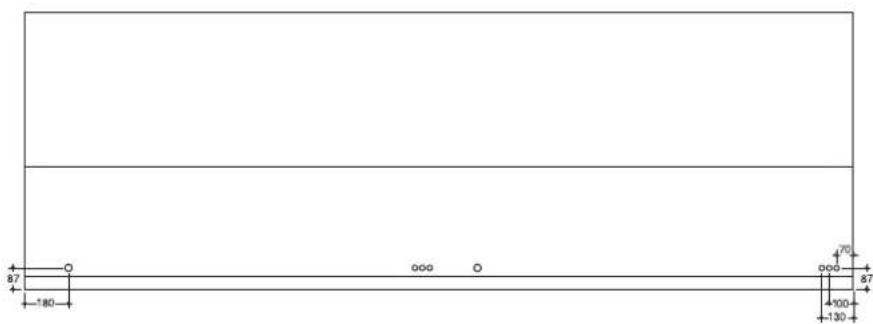
Hybrid 3300 - Right Hand Model
PLAN

LHS
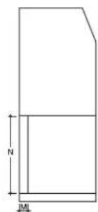
FRONT
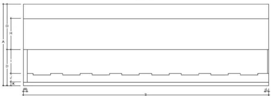
RHS

ZERO CLEARANCE HYBRID INSTALLATION
Timber Frame Installation

Frameout Dimensions (in mm)
| MODEL A B C D |
| HYBRID 1000 1020 1150 475 2100 |
| HYBRID 1500 1100 1650 475 2100 |
| HYBRID 1800 1235 1950 475 3000 |
| HYBRID 3300L&R Assembled 1235 3450 475 3600 |
CLEARANCES FROM COMBUSTIBLES
| Floor 0 mm |
| Sides 25 mm |
| Top 100 mm |
| Flue Outer 25 mm |
ZERO CLEARANCE HYBRID INSTALLATION
Installation Procedure
TICK BOXES
☐ Check frame out has been constructed correctly and has not been plastered.
☐ Check frame out and structure above is clear of any structures that may impede the flue run. If the flue needs to be off set with 45 deg bends, the offset length can be no more than 20% of the total flue run. It is recommended that after the last bend at least two full lengths of flue are added in the vertical.
☐ Ensure an adequately sized gas connection is available within the frame out, a 15mm gas copper pipe is to be provided into the firebox. An access hole is provided in the back of the firebox. A 500mm tail is required into the firebox to allow for connection to the burner.
☐ Position the unit ensuring the wiring loom and gas pipe are accessible.
☐ Connect the twin skin flue (or Optional Power Flue if supplied).
☐ Install an AGA approved gas cowl ensuring the termination meets all relevant code requirements.
☐ Connect the gas line to the burner connection using the 15mm flared copper union (supplied).
☐ Connect the wiring terminals to the ignition pack as shown below.
Note: Do not locate the switch further than 6 meters from the firebox.
Place the burner surround or optional front or marble base over the burner.
Place the coals or optional pebbles randomly on the ceramic blanket. If coals and logs option is supplied, place logs on top of coals randomly.
IMPORTANT! Only ceramics supplied by Glen Dimplex are to be used.

LIGHTING MAIN BURNER
FOR YOUR SAFETY READ BEFORE LIGHTING
■ Before igniting the fire, check for gas leaks.
■ Use only the ignition components supplied.
Do not use this appliance if any part has been under water. Immediately call a qualified service technician to inspect the appliance and replace any part of the control system and any gas control that has been under water.
LIGHTING INSTRUCTIONS
- STOP! Read the safety information before proceeding.
- Turn on the remote wall switch.
- If the fire will not stay lit after several tries turn the switch to "OFF" and call your service technician or gas supplier.
TO TURN OFF GAS TO APPLIANCE
- Turn off the remote wall switch.
TESTS TO BE CARRIED OUT BY INSTALLER
- Carry out a smoke test to ensure the fireplace is drawing.
- Test that the Test Point Pressures are correctly set.
- Check that there are no gas leaks form any of the fittings.
- Explain to the customer how the unit operates and how to turn it on and off.
FAILURE PROCEDURE
If when the wall switch is turned to the “ON” position and the fire fails to ignite, check the following:
- Ensure that the wiring terminals are not loose.
- Test that the inlet and working pressures are both correct.
FLUE REQUIREMENTS
Natural Draught
The standard natural draught flue kit consists of 4 x 900mm lengths of twin skin flue (refer to page 6 for correct sizing) and an AGA approved cowl.

These notes must be read in conjunction with AGA code 601.

A minimum of 3.6m flue is required to protrude 500mm above roof line.
Flue can be offset with two 45° bends no more than 20% of overall height of flue.
CLEARANCES
| Floor 0 mm |
| Sides 25 mm |
| Back 25 mm |
| Top 100 mm |
| Flue Outer 25 mm |
FLUE REQUIREMENTS
Power Flue Kit (Optional - refer to pages 15 to 27 for details)
The standard Power Flue Kit consists of ;
- 1 x Power Flue Fan
- 1 x Power Flue Motor
- 1 x Control Module
• 1 x Electronic Ignition Pack - 1 x Baffle
• 1 x Pressure Differential Switch - 1 x Loom
- 1 x Termination Cowl (horizontal or vertical)

A ‘flue’ using a fan to remove or assist in removing combustion products from an appliance, is known as a ‘power flue’.
A power flue application can be used to enable a client to have a decorative fire with a horizontal flue run or a vertical flue run where flue space is inadequate for the normal flue.
WHERE FITTED A POWERFLUE SYSTEM MUST BE DESIGNED AND INSTALLED TO MEET GAS INSTALLATION CODES AS5601.1.2013 CLAUSE H2 - POWER FLUE DESIGN.
Where the powerflue option described in this manual is installed, it represents a Power Flue installed in accordance with AS/NZS 5601.1 Paragraph H2. The powerflue system when installed to the instructions is designed to comply with the requirements of AS/NZS5601.
The powerflue must be installed and commissioned by the installer in accordance with Paragraph H2.2.7 AS/NZS 5601.1.
INSTALLATION INSTRUCTIONS
VENTILATION REQUIREMENTS
A requirement of the gas installation code AS/NZS5601.1-2013 is that ventilation is required as per the manufacturers instructions. Clause 6.10.9.5 of AS/NZS5601.1-2013 sets out the ventilation requirements.
Ventilation requirements of models installed with Power Flue
| MODELS Ventilation Sq mm |
| Double Vision, Hot Box and all Heatseekers 18,000 |
| Pure Vision, Simplicity, Elegance, Signature, Hybrid 1000 & 1500 Sizes 18,000 |
| Pure Vision, Simplicity, Elegance, Signature, Hybrid 1800 Sizes 32,000 |
| Pure Vision, Simplicity, Elegance, Signature, Hybrid 3300 Size 64,000 |
ACCESS TO POWER FLUE MOTOR
Access must be provided to the flue motor, this access MUST be at least 400mm x 400mm. There MUST be a minimum clearance of 250mm between the top of the motor and any fixed object i.e. ceiling or stud work. This is so the top of the fan box can be removed.
WIRING OF THE POWER FLUE
All wiring for the power flue is carried out at the factory and plug connectors are fitted for easy installation. The power supply for the power flue is via a 3-pin plug at the rear of the firebox that can be plugged into a power socket within the cavity.
ISOLATION SWITCH
If the power point is within a cavity an isolation switch accessible from outside the cavity must be provided.
WIRING CLEARANCES
Wiring must at all times have a clearance of at least 150mm from the flue.
FAN FAILURE SENSING DEVICE
All Glen Dimplex Power Flue systems are fitted with a sensing device within the unit to ensure that, in the event of flow failure, the safety shut off valve within the module will go into lockout and shut off the gas supply to the unit. The device should ALWAYS be in the vertical position. Refer to the pressure differential switch on page 15.
'LOCKOUT'
'Lockout' is the term used when the module in the unit senses a fault. When a fault is detected by the module it will shut off the gas and go into lockout. If this occurs contact the manufacturer.
INSTALLATION INSTRUCTIONS (continued)
Listed below are the minimum clearances required for fan-assisted terminations:
- Below eaves, balconies and other projections. 200mm
1a. Below eaves, balconies and other projections for a 1500 & 1800 model ....300mm - From the ground, above a balcony or other surface....300mm
- From a return wall or external corner....300mm
- From a G as meter....1000mm
- From an electricity meter or fuse box. 500mm
- From a drainpipe or soil pipe....75mm
- Horizontally from any building structure or obstruction facing a terminal. .....500mm
- From any other flue terminal. Cowl, or combustion air intake. 300mm
- Horizontally from any openable window, door, non-mechanical air inlet, or any other opening into a building with the exception of sub floor ventilation.....300mm
- From a mechanical air inlet including a spa blower....1000mm
- Vertically below an openable window, non-mechanical air inlet, or any other opening into a building with the exception sub floor ventilation.....500mm
ELECTRICAL
SHOULD THE SUPPLY FLEX AT THE BACK OF THE FIREBOX BE DAMAGED, A SPECIALLY PREPARED FLEX IS REQUIRED. FOR REPLACEMENT CONTACT THE MANUFACTURER.
THE ON/OFF WALL SWITCH MUST NEVER BE ATTACHED TO A METAL FRAME.
WARNING
Whenever servicing the power flue system, always turn off the electrical power supply and close the manual gas control valve.
IMPORTANT INFORMATION
In addition to the instructions in this manual all national, state and local regulations must be adhered to. These include but are not limited to:
• Australian Standards AS3000 - Electrical Installation.
• Australian Standards AS/NZS5601.1-2013 - Gas Installation.
- Local Gas and Electrical Authority Regulations.
• Municipal Building Codes.
The power flue should be serviced every 12 months by an authorised technician. If repairs are needed an authorised technician must carry them out.
FITTING THE MOTOR
The Power Flue motor is fitted with two sets of spigots. The set on the base of the Power Flue box sit on top of the vertical flue and the set mounted on the side plate connect to the horizontal flue.
The 1800, 3000 and 3300 units have a power flue motor with a 200mm spigot and a twin spigot of 200mm and 250mm.
INSTALLATION INSTRUCTIONS (continued)
FLUE SIZE
The flue size for each model is different. Please refer to the table below.
| MODELS A mm B mm |
| Double Vision, Hot Box and all Heatseekers 150 200 |
| Pure Vision, Simplicity, Elegance, Signature, Hybrid 1000 & 1500 Sizes 150 200 |
| Pure Vision, Simplicity, Elegance, Signature, Hybrid 1800 & 3300 Sizes 200 250 |
NOTE: Ensure all power flue inner and outer flue lengths are sealed at joins.
HORIZONTAL FLUE RUN
The maximum length of horizontal flue run is to be 13.5 metres with a maximum of four (4) bends; these bends can be 45° or 90° . The horizontal flue run is to have a grade downwards from the motor to the termination.
VERTICAL FLUE RUN (see page 20)
The minimum vertical flue run is 900mm from the top of the firebox (1500mm from the floor). If a longer vertical run is required twin skin flue 150mm & 200mm can be added between the muffler top and the fan. The flue can be cut to the required height. For 1800 and 3300 units 200mm/250mm flue is required.
FLUE CLEARANCES
All flue clearances are as per the requirements listed in the heater specifications.
TERMINATION
The termination to be used for all horizontal installations is to be either a small flush cowl or if used as a service access panel, a large flush cowl is required. For vertical termination a vertical approved cowl must be used. An external motor can be used as an option on horizontal and vertical terminations.
INSTALLATION OF POWER FLUE KIT
POWER FLUE MUFFLER
The power flue muffler has a spigot at each end. The end that attaches to the firebox has a spigot equivalent to the inner flue spigot diameter of the firebox, the top of the muffler has a 150mm spigot which the motor fits to, or the 150/200 twin skin flue if required. The flow arrow on the muffler is to be pointing up. If a 1800 or 3300 unit is used the flue is 200mm/250mm.
WIRING (see wiring diagram page 27)
A 3 metre lead is supplied with the power flue, this lead has a different connection on each end, one end is plugged into the connection on the left hand side of the firebox and the other end is to be plugged into the fan. The wire coming from the rear of the firebox with the standard 3-pin plug attached is to be plugged into a power point. A single gang wall switch is also supplied attached to the 3 metres of lead; this wall switch is to be attached at a location accessible to the client. No other wiring is required.
SERVICING OF THE POWER FLUE MOTOR
The Glen Dimplex Power Flue motor is designed so as to make servicing the motor a simple task. The power lead connected to the motor is to be disconnected (unplugged) and the screws are to be undone, the fan motor will then lift out for servicing. The fan Motor box connected to the flue does not have to be disconnected from the flue.
COMMISSIONING THE POWER FLUE SYSTEM
THE INSTALLER MUST COMMISSION THE POWERFLUE SYSTEM AS PER CLAUSE H2.2.7 (AS5601.1.2013)
The correct CO2 concentration shall be established by adjustment of dampers and checked by flue gas analysis. A check that the controls are operating in the manner specified shall be carried out.
The check shall include a simulation of fan failure.
Commissioning the powerflue systed is an additional requirement to commissioning the appliance. The appliance must also be commissioned as per AS5601.1.2013.
Sizing of the fan
In order to select a suitable fan, it is necessary to determine the volume and temperature of the flue gases. Before this can be done the percentage of CO2 in the flue gases shall be decided.
If discharge is at a low level, 1% CO 2 may be used in the design formula. For other situations, values between 4% and 8% may be used. These values will give flue gas temperatures of 140°C and 220°C respectively.
For appliances with modulating burners, the CO2 concentration in the flue shall be considered when the appliance is operating at normal rate, i.e. 8% CO2 in the combustion chamber.
The quantity of flue gases to be handled by the fan may be determined by the following simplified formula, which is sufficiently accurate for most flue gases currently distributed. A suitable fan may then be selected.
Q = T/R
Where Q = volume of flue gases, litres per second
T = total gas consumption of appliances connected to flue megajoules per hour
R = desired % CO₂ concentration by volume in the flue gases at the discharge point
FLUE GASES - RELATIONSHIP BETWEEN % CO₂ VOLUME FLOW RATE & % EXCESS AIR
CO 2 % Volume Flow Rate L/s/MJ/h Excess Air %
10 0.10 33
9 0.11 50
8 0.13 67
70.1490
6.7 0.15 100
6 0.17 120
5 0.20 170
4.4 0.23 200
4 0.25 230
3.3 0.30 300
3 0.33 400
2.2 0.45 500
2 0.50 500
1.7 0.60 700
1.2 0.80 1000
1.0 1.00 1200
0.8 1.20 1500
0.6 1.60 2000
0.5 2.00 2600
POWER FLUE MOTOR CLEARANCE
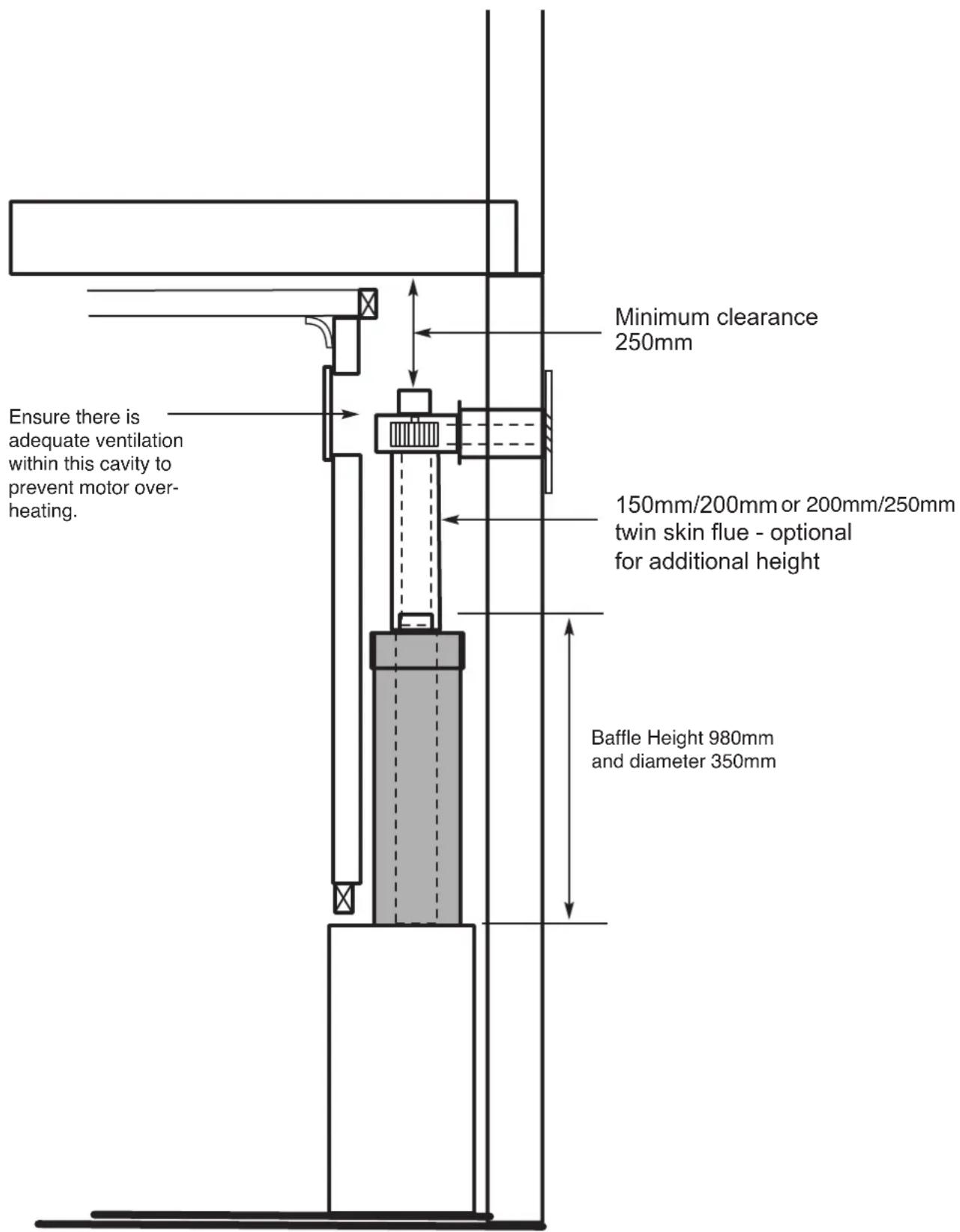
TYPICAL POWER FLUE FRAMEOUT

INTERNAL MOTOR

NOTE:
- Maximum of 4 elbows, 45° or 90° .
- Allow 400mm x 400mm access panel for service of motor.
EXTERNAL MOTOR
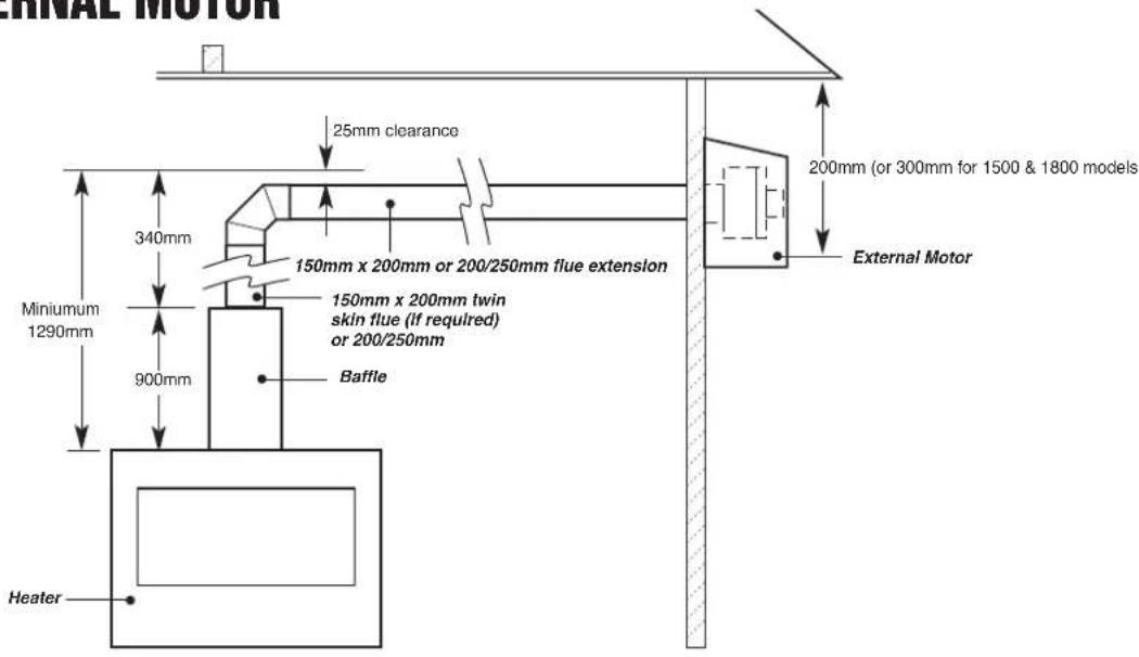
NOTE:
- Maximum of 4 elbows, 45° or 90° .
DIMENSIONS
External Flue Motor

| A | B | C | D | E | F | G | H |
| 302 | 348 | 345 | 55/5 | 90/40 | 20 | 200/250 | 150/200 |
| I | J | K | L | M | N | O | P |
| 13 | 20 | 120 | 60 | 105 | 75 | 45 | 112 |
| MODELS | H mm | G mm |
| Double Vision, Hot Box and all Heatseekers | 150 | 200 |
| Pure Vision, Simplicity, Elegance, Signature, Hybrid 850, 1000 & 1500 Sizes | 150 | 200 |
| Pure Vision, Simplicity, Elegance, Signature, Hybrid 1800, 3000 & 3300 Sizes | 200 | 250 |
Power Flue Flush Termination 500 x 500


Power Flue Flush Termination 300 x 300


REAR

DIMENSIONS
Internal Power Flue Motor
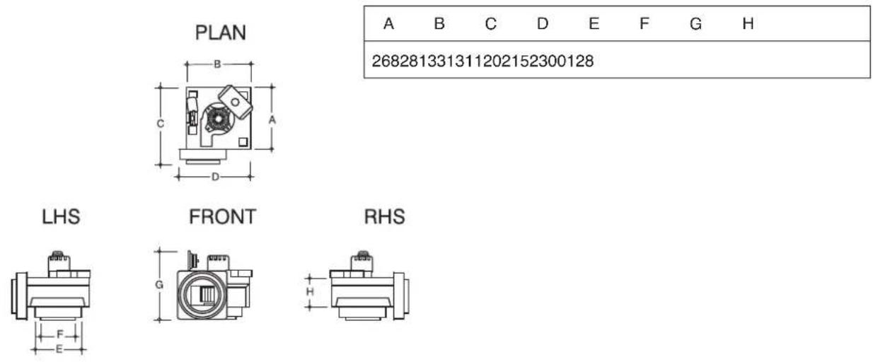
| A | B | C | D | E | F | G | H |
| 268281331311202152300128 | |||||||
Internal Power Flue Motor 200/250

| A | B | C | D | E | F | G | H | |
| PLAN | 268281322 | 336 | 252202336128 | |||||
TROUBLE SHOOTING FOR ELECTRONIC IGNITION AND POWER FLUE SYSTEM.
| Symptom | Possible Cause | Corrective Action |
| Fire turned on and nothing happens | No Power to Module | Connect Power |
| Fire turned on and motor starts but there is no spark | Pressure switch not operating | Check pressure switch |
| Fire sparks when turned on but will not ignite | A. No Gas Connect Gas. | |
| B. Sparker is to far from metal | Adjust sparker so it cross lights to metal. | |
| C. Pressure switch (Power Flue) is not operating correctly. | Remove fan from housing and check that small tube supplying air to pressure switch has not moved or been damaged. | |
| C. Valve solenoids are faulty | Check solenoids | |
| D. Solenoid wires to module not connected correctly | Check that the four pin plug from the valve has been connected correctly | |
| Fire ignites and then shuts down within a couple of seconds | A. Something is touching the heat sensor | Ensure that nothing is touching the sensor which is located behind the cover plate at front of burner. |
| B. The power polarity is reversed | Check polarity | |
| Fire ignites and shuts down after several minutes | A. Insufficient air for burner to operate correctly | Check that the unit has correct ventilation as per Installation manual. |
| B. Pressure switch not operating correctly | Check air supply tube to pressure switch. |
TROUBLE SHOOTING FOR ELECTRONIC IGNITION AND POWER FLUE SYSTEM. (continued)
The power flue and electronic control box have a red LED light that indicates the possible cause of a problem, the LED light will flash in different sequences for different problems, the most common are:-
Long Flash Short Flash
| 1 | 0 | Normal Running State. |
| 1 | 1 | Flame Failure. |
| 1 | 2 | Waiting for pressure switch ON |
| 1 | 3 | Waiting for pressure switch OFF |
| 2 | 1 | Maximum retries exceeded |
POWER FLUE WIRING DIAGRAM
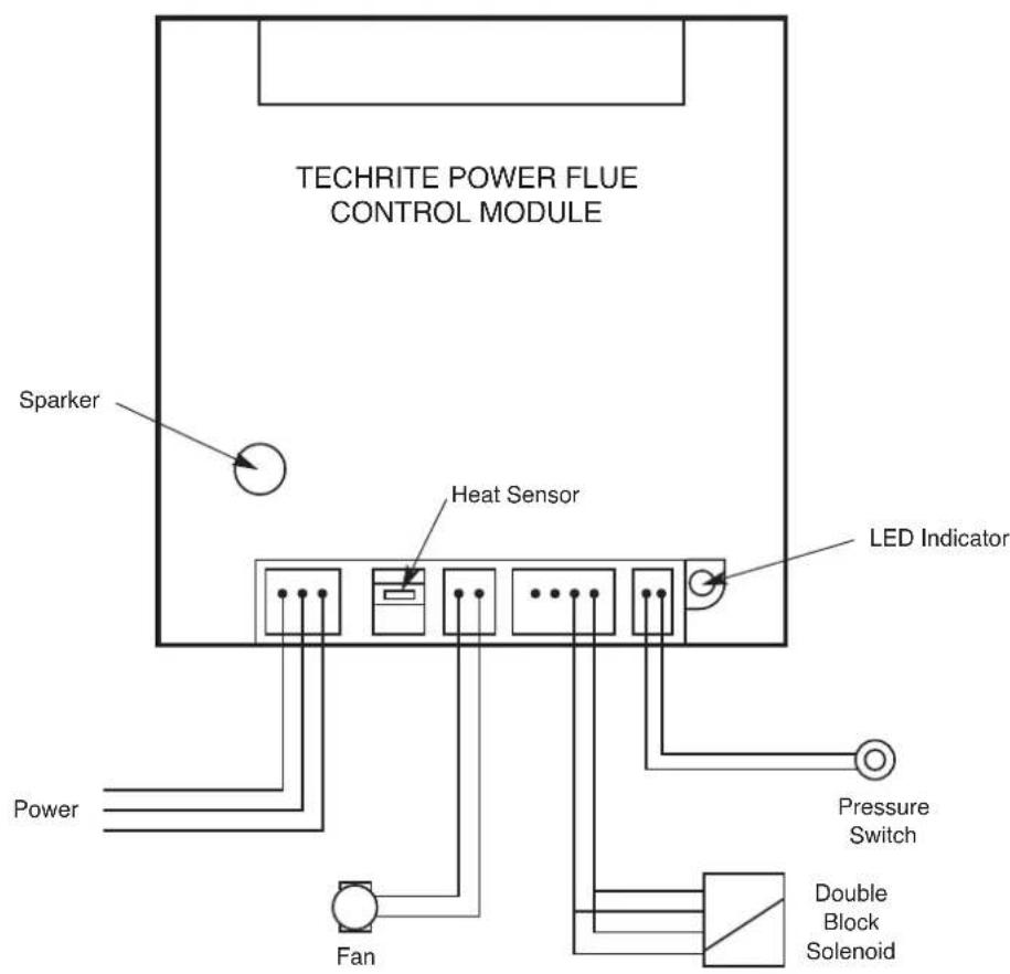
NOTE
For C Bus and/or fresh air damper interlock systems, please contact us for wiring diagrams and relevant system instructions at info@realflame.com.au

White Rogers Valve Used For Electronic Ignition For 850 & 100 Modular Boxes.
Part Number: W0079

Dungs Valve used On 1400 Burner In 1800 Modular Box.
Part Number: DUBM 241221

Sparker and Sensor Fitted to all Electronic Ignitions.
Part Number: GST0829985
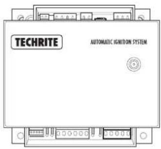
Techrite Electronic Ignition Module.
Part Number: TAIS00RISD5

Techrite Power Flue Module used on all Power Flue Models.
Part Number: TAISCPRI5DS

Regulator fitted to all Natural Gas 1400 Magiglo Burners.
Part Number: 2369
MARBLE BASES AND FRONTS
**NOTE: The bases used should be manufactured from a non-combustible material such as metal or natural stone. Reconstituted stone and other materials which may contain resins or combustible components should not be used. The base should not be stuck down under any circumstances as it is used for access to the burner and other components.

Note: I & J are for Hybrid versions of Simplicity/Purevision where glass is fitted to one side and one side is solid. Left Hand Hybrid means the glass is on the left, and Right Hand means the glass is on the right.
| MODEL A | B | C | D | E | F | G | H | I# J# | |||
| HYBRID 1000 | 765 | 425 | 997 | 212 | 170 | 997 | 116 | 116 | 130 | 115 | |
| HYBRID 1500 | 1215 | 425 | 1495 | 232 | 170 | 1495 | 140 | ||||
| HYBRID 1800 | 1415 | 425 | 1795 | 232 | 170 | 1795 | 190 |
I & J are based on a Left Hand Hybrid. Reverse for Right Hand unit.

www.realflame.com.au
1300 554 155
- WARRANTY INFORMATION
- WARRANTY
- REGISTRATION
- EXCLUSIONS
- LIMIT OF LIABILITY
- CLAIMING UNDER THE WARRANTY
- INSTALLATION NOTICE
- IMPORTANT SAFETY NOTICES
- WARNING
- SERVICING
- CONTENTS
- DATA PLATE (AFFIXED TO THE BASE OF THE UNIT FOR REFERENCE TO GAS PRESSURE & CONSUMPTION)
- HYBRID 1000 & HYBRID SIGNATURE 1000
- HYBRID 1500 & HYBRID SIGNATURE 1500
- HYBRID 1800 & HYBRID SIGNATURE 1800
- HYBRID 3300L & HYBRID 3300R, HYBRID SIGNATURE 3300L & HYBRID SIGNATURE 3300R
- ZERO CLEARANCE MODULAR INSTALLATION
- DIMENSIONS
- HYBRID 1500 - LEFT HAND MODEL
- HYBRID 1500 - RIGHT HAND MODEL
- HYBRID 1800 - LEFT HAND MODEL
- HYBRID 1800 - RIGHT HAND MODEL
- HYBRID 3300 - LEFT HAND MODEL
- HYBRID 3300 - RIGHT HAND MODEL
- ZERO CLEARANCE HYBRID INSTALLATION
- INSTALLATION PROCEDURE
- TICK BOXES
- LIGHTING MAIN BURNER
- FOR YOUR SAFETY READ BEFORE LIGHTING
- LIGHTING INSTRUCTIONS
- TO TURN OFF GAS TO APPLIANCE
- TESTS TO BE CARRIED OUT BY INSTALLER
- FAILURE PROCEDURE
- FLUE REQUIREMENTS
- NATURAL DRAUGHT
- POWER FLUE KIT (OPTIONAL - REFER TO PAGES 15 TO 27 FOR DETAILS)
- INSTALLATION INSTRUCTIONS
- VENTILATION REQUIREMENTS
- ACCESS TO POWER FLUE MOTOR
- WIRING OF THE POWER FLUE
- ISOLATION SWITCH
- WIRING CLEARANCES
- FAN FAILURE SENSING DEVICE
- LOCKOUT
- INSTALLATION INSTRUCTIONS (CONTINUED)
- ELECTRICAL
- IMPORTANT INFORMATION
- FITTING THE MOTOR
- FLUE SIZE
- HORIZONTAL FLUE RUN
- VERTICAL FLUE RUN (SEE PAGE 20)
- FLUE CLEARANCES
- TERMINATION
- INSTALLATION OF POWER FLUE KIT
- POWER FLUE MUFFLER
- WIRING (SEE WIRING DIAGRAM PAGE 27)
- SERVICING OF THE POWER FLUE MOTOR
- COMMISSIONING THE POWER FLUE SYSTEM
- SIZING OF THE FAN
- POWER FLUE MOTOR CLEARANCE
- TYPICAL POWER FLUE FRAMEOUT
- NOTE
- EXTERNAL FLUE MOTOR
- POWER FLUE FLUSH TERMINATION 500 X 500
- POWER FLUE FLUSH TERMINATION 300 X 300
- INTERNAL POWER FLUE MOTOR
- INTERNAL POWER FLUE MOTOR 200/250
- TROUBLE SHOOTING FOR ELECTRONIC IGNITION AND POWER FLUE SYSTEM. (CONTINUED)
- POWER FLUE WIRING DIAGRAM
- MARBLE BASES AND FRONTS
- NOTE: I & J ARE
- NOTE: I & J ARE FOR HYBRID VERSIONS OF SIMPLICITY/PUREVISION WHERE GLASS IS FITTED TO ONE SIDE AND ONE SIDE IS SOLID. LEFT HAND HYBRID MEANS THE GLASS IS ON THE LEFT, AND RIGHT HAND MEANS THE GLASS IS ON THE RIGHT
Brand : Real Flame
Model : Hybrid 1500
Category : Heating