GP8502P - Uncategorized Netis - Free user manual and instructions
Find the device manual for free GP8502P Netis in PDF.

| Product Type | 8-Port Gigabit PoE Switch |
| Dimensions (W x D x H) | 200 x 130 x 40 mm |
| Weight | 0.5 kg |
| Power Supply | External DC adapter, 48V 1.5A |
| Number of Ports | 8 x Gigabit Ethernet with PoE |
| PoE Budget | 120W total |
| Switching Capacity | 16 Gbps |
| MAC Address Table | 8K entries |
| Main Functions | PoE power supply, data switching, auto-negotiation, flow control |
| Care and Cleaning | Wipe with a dry cloth; do not use liquid cleaners |
| Safety Precautions | Keep away from moisture and heat; ensure proper ventilation |
| Spare Parts and Reparability | Power adapter available; no user-serviceable parts inside |
| General Information | Brand: Netis; Model: GP8502P |
Frequently Asked Questions - GP8502P Netis
User questions about GP8502P Netis
0 question about this device. Answer the ones you know or ask your own.
Ask a new question about this device
Download the instructions for your Uncategorized in PDF format for free! Find your manual GP8502P - Netis and take your electronic device back in hand. On this page are published all the documents necessary for the use of your device. GP8502P by Netis.
USER MANUAL GP8502P Netis
netis PON Terminal
Quick Installation Guide

* This Q/Q is for notes PCN Terminal, including models- EP8101Q, EP8104, EP8104P, GP8501G, GP8501GP, GP8502P.
* The product image shown in this QIG is EP8104P, as an example.
2.Hardware Connection
text_image
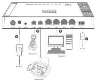
Diagram of a network equipment rack with labeled ports and components including power, telephone, computer, and printer2.1. Connect the fiber. Plug one end of the fiber into the PON port.
2.2. Connect the Ethernet cable. Attach one end of a network cable to your computer's Ethernet port, and the other end to the LAN port.
2.3. Connect the telephone line. Attach one end of a telephone line to your telephone/voice port/fax machine, and the other end to the PHONE port. (Optional)
2.4 Attach the power adapter. Plug the provided Power Adapter into the PWR jack of netia ONU and the other end to a standard electrical socket.
3.LED and Button Description
| LED | Color | Status | Indication |
| PWR | Green | On | The ONU is powered on. |
| Off | The ONU is powered off. | ||
| LOS | Red | On | The PON optical module is powered off. |
| Flashing | The received optical power of the ONU is lower than the optical receiver sensitivity. | ||
| Off | The ONU receives optical power normally. | ||
| PON | Green | On | The ONU has connected to the OLT. |
| Flashing | The ONU is trying to set up a connection to the OLT. | ||
| Off | The ONU fails to connect to the OLT. | ||
| LAN/ITV | Green | On | There is a device connected to the corresponding LAN port, but there is no data being transferred. |
| Flashing | The device is sending or receiving data over the corresponding LAN port. | ||
| Off | There is no device connected to the corresponding LAN port. | ||
| PHONE(For GPS1047, GPS101GP, GPS102P) | Green | On | The ONU has been registered the server. |
| Flashing | The PHONE port is transferring data. | ||
| Off | The ONU can't register the server. | ||
| RUN(For GPS101GP, GPS101G) | Green | On | There's a hardware failure. |
| Off | The ONU is powered off or there's a hardware failure. | ||
| Flashing(1s interval) | The ONU is working normally. | ||
| Flashing(300ms interval) | There's a software failure. |
| Button | Description |
| Default | The Default button is used to set factory defaults. |
| ON/OFF | The ON/OFF button is used to power on and power off. |
neta PON Terminal Quick Installation Guide
rieta PDM Terminal Quick installed on Guide
netto PON Terminal Quick Instantation Guide
4. Login the ONU via Web Management Page
4.1. Manually set the IP address of the wired network adapter on your computer as below.
IP Address/IPv4 Address: 192.168.2.X (1 < X < 254. X: 201)
Subnet Mask: 265,265,265.0 Default Gateway/Router 193-158-2-201
For Windows 8/7/Vista
1) Go to "Settings" (for Windows 8)/"Start" (for Windows 7/Vista) > "Control Panel"
2) Left-click on "Network and Internet" > "Network and Sharing Center" >
"Change adapter settings" (for Windows 8/7)/Manage network
connections" (for Windows Vista).
3) Right-click on "Local Area Connection" and left-click on "Properties" 4) Double-click on "Internet Protocol Version 4 (TCP/IPv4)"
4) Double-click on Internet Protocol Version 4 (TCP/IPV4) 5) Select "Use the following IP address": set like above IP
5) Select "Use the following IP address", set the above IP parameters and then left-click on "OK"
For Windows XP/2000
1) Go to "Start" > "Control Panel".
2) Left-click on 'Network and Internet Connections' > 'Network
Connections
3) Right-click on "Local Area Connection" and left-click on "Properties".
4) Double-click on "Internet Protocol (TCP/IP)"
5) Select "Use the following IP address", set the above IP parameters and
then left-click on "OK"
For MAC OS
1) Click on the "Apple" menu > "System Preferences"
2) Click on the "Network" icon.
3) Click on "Ethernet" in the left side box and click on "Advanced" in the lower
right corner.
4) in the top options, select "TCP/IP".
5) In the pull-down menu next to "Configure ipv4" select "Manually"
6) Fill in the "IPv4 Address/Subnet Mask/Router" parameters, and click "OK"
then "Apply"
4.2. Open your browser and type 192.168.2.201 in the address field. Then type in the username guest and password guest to login the web management page.
e 192.168.2.201
4.3. You will see the following ONU management page to finish the further settings.
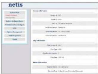
text_image
netis System Tools C:\Users\My Documents C:\Users\Design\Tools Web Development Options HKEY System Management FISI Management Internet Internet Information Image (0, 1) Image (0, 2) SQL Server - SQL Server Database Server - SQL Server Database Server - SQL Server Database Server - SQL Server File Information C:\Users\My Documents C:\Users\My Documents C:\Users\My Documents C:\Users\My Documents Internet Information Internet (0, 1) C:\Users\My Documents C:\Users\My Documents C:\Users\My Documents Internet Information Internet (0, 1) C:\Users\My Documents C:\Users\My Documents C:\Users\My Documents5.Troubleshooting
What can I do if the Power LED does not light up?
1) Make sure that the ONU is properly plugged into a power outlet and pre-
check if the power outlet is working time. 31) looking and plus the ONU into the power outlet again. If the Power LED
2) Englog and plug the cold into the power drain again. If she Power still fails to light up, contact your local dealer for technical support.
What can I do if the LOS LED is always red on?
A 1) Make sure that the fiber is plugged into the PON port family and the fiber
cable is not broken.
2) If the LOS LED still sold on, which means that the
What can I do if the PON LED does not light up?
10
A: 1) Make sure that the power is on, and the fiber connection is running properly. 2) If all the hardware connection is fine but the PON LED is still off, please contact your ISP for further help.
How do I restore my nella ONU's configuration to its default settings?
A With the ONU powered on, use a pin to press and hold the Default button on the rear panel for 5 seconds at last before releasing it. The ONU will reboot and all configurations are back to factory default.
Appendix: FCC Statement
This device complies with Part 15 of the FCC Rules. Operation is subject to the following two conditions.
(1) this device may not cause harmful interference and
(2) this device must accept any interference received; including interference that may cause undesired operation.
This equipment has been tested and found to comply with the limits for a Class B digital device, pursuant to part 15 of the FCC rules. These limits are designed to provide reasonable protection against harmful interference in a residential installation. This equipment generates, uses and can radiate radio frequency energy and, if not installed and used in accordance with the instructions, may cause harmful interference to radio communications. However, there is no guarantee that interference will not occur in a particular installation. If this equipment does cause harmful interference to radio or television reception, which can be determined by turning the equipment off and on, the user is encouraged to try to correct the interference by one or more of the following measures:
increase the separation between the equipment and receiver
-Connect the equipment into an outlet on a circuit different from that to which the receiver is connected.
-Consult the dealer or an experienced radio/TV technician for help.
Warning
[A shielded-type power cord is required in order to meet FCC emission limits and also to prevent interference to the nearby radio and television reception. It is essential that only the supplied power cord be used.]
[Use only shielded cables to connect I/O devices in this equipment.]
You are cautioned that changes or modifications not expressly approved by the party responsible for compliance could void your authority to operate the equipment.
[ ] depend on EUT condition.
NETIS SYSTEMS CO., LTD.
www.nella-systems.com
MADE IN CHINA
PHUMOLO
-
4