MDUO18048060 - Air Conditioning MRCOOL - Free user manual and instructions
Find the device manual for free MDUO18048060 MRCOOL in PDF.

| Product Type | Ductless Mini-Split Air Conditioner |
| Model Number | MDUO18048060 |
| Brand | MRCOOL |
| Cooling Capacity | 18,000 BTU |
| Heating Capacity | 18,000 BTU (Heat Pump) |
| SEER Rating | Up to 20 |
| Voltage | 208-230 V |
| Phase | Single Phase |
| Frequency | 60 Hz |
| Indoor Unit Dimensions (WxHxD) | 36.0 x 12.5 x 8.0 inches |
| Outdoor Unit Dimensions (WxHxD) | 34.5 x 26.0 x 14.0 inches |
| Indoor Unit Weight | 30 lbs |
| Outdoor Unit Weight | 135 lbs |
| Refrigerant | R-410A |
| Noise Level (Indoor) | 20 - 45 dB(A) |
| Noise Level (Outdoor) | 55 - 60 dB(A) |
| Thermostat Control | Yes, with remote |
| Remote Control | Included (IR) |
| Filter Type | Washable, reusable |
| Drainage | Condensate drain included |
| Installation Type | Wall-mounted, ductless |
| Energy Star Rated | Yes |
| Warranty | 7 years (compressor), 2 years (parts) |
Frequently Asked Questions - MDUO18048060 MRCOOL
User questions about MDUO18048060 MRCOOL
0 question about this device. Answer the ones you know or ask your own.
Ask a new question about this device
Download the instructions for your Air Conditioning in PDF format for free! Find your manual MDUO18048060 - MRCOOL and take your electronic device back in hand. On this page are published all the documents necessary for the use of your device. MDUO18048060 by MRCOOL.
USER MANUAL MDUO18048060 MRCOOL
natural_image
Abstract blue logo design resembling a stylized animal or mythical creature (no text or symbols)MRCOOL®
COMFORT MADE SIMPLE
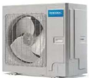
DC INVERTER HEAT PUMP CONDENSING UNIT SERVICE MANUAL
Capacity: 24kBtu/h\~60kBtu/h
Rate Frequency: 60Hz
Operation Range:
Cooling: 5°F (-15°C)\~129.2°F (54°C)
Heating: -22^ F(-30^ C) 75.2^ F(24^ C)
natural_image
Exterior view of a modern air conditioning unit with fan and ventilation grille (no visible text or symbols)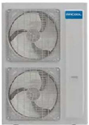
natural_image
Two identical air purifiers with visible blades and grid patterns, no text or symbols present.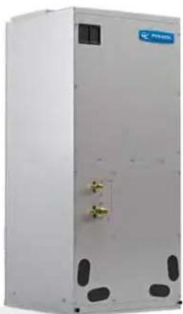
natural_image
Exterior view of a white industrial cabinet with gold connectors and ventilation slots (no visible text or symbols)Foreword
Thank you for choosing MRCOOL Universal air conditioners. In order to correctly install and use our units, and for the satisfactory operation effect, please read this manual carefully.
This manual specifies safe operation requirements from perspectives of product introduction, control, troubleshooting and maintenance, as well as basic principles and implementation methods. Professional operators must abide by relevant national (local) safety requirements and technical specifications set forth in this manual during operations; otherwise, the air conditioning system may fail or be damaged, and personnel safety accident may also occur.
Safety Notice
 | Before using the air conditioner, please first read the instruction manual. |
 | Before installing the air conditioner, please first read the instruction manual. |
 | Before repairing the air conditioner, please first read the technical service manual. |
CONTENTS
1 Product Introduction ....3
1.1 Lists of Units ....3
1.2 Electrical Parameters....5
2 Control....6
2.1 Operation Mode ....6
2.2 Control Mode 8
2.3 Functions....10
3 Troubleshooting....14
3.1 Wiring Diagrams ...... 14
3.2 PCB Layout....17
3.3 Error Code 25
3.4 Troubleshooting ....26
3.5 Failures Not Caused by Errors....53
4 Maintenance....55
4.1 System Diagram ....55
4.2 Connection Pipe Vacuum Pumping 55
4.3 Refrigerant Charging....57
4.4 Maintenance of Major Components....59
4.5 Removal of Major Components....69
4.6 Explosive View and Lists of Parts....104
Appendices 110
1 Resistance/Temperature Lists of Temperature Sensors .... 110
1.1 Voltage List of 15 KΩ Temperature Sensors.... 110
1.2 Voltage List of 20 KΩ Pipeline Temperature Sensors .... 112
1.3 Voltage List of 50 KΩ Discharge Temperature Sensors....114
2 Temperature/Pressure List of Refrigerant 117
3 Operation Tools 117
Safety Notice on Maintenance

PROHIBITED:
(1) Do not pierce or burn.
(2) Please note that refrigerant may be odorless.
(3) The appliance shall be stored in a room without continuously operating ignition sources (For example: open flames, an operating gas appliance or an operating electric heater).
(4) Indoor unit adopts special joints that can't be detached. The installation method is the same with the common joints. However, because the joint can't be detached, if it is badly connected and causes leakage, it needs to be cut and replaced by a new one through welding.
(5) Using unsuitable parts or tools may lead to electric shock or fire hazard.
(6) If refrigerant leaks during maintenance, please ventilate the room immediately. Heavy leakage may lead to breathing difficulty, severe injury or death.
(7) Disconnect power before disassembling the appliance for maintenance.
(8) The appliance should be maintained and cared by authorized technical personnel with necessary qualifications.

WARNING:
(1) If the working place is more than 6.5 Feet high, please wear a safety helmet, gloves and a safety belt.
(2) Never mix any other substances except the specified refrigerant into the refrigerant circuit.
(3) When re-locating the appliance, check whether the new location is strong enough to withstand the weight of the appliance.
(4) If there is refrigerant leak, please fix the leak before charging in the refrigerant. After refrigerant is charged, check for refrigerant leaks. If you cannot spot the leak, stop the maintenance work. Please evacuate the system and close the service valve to prevent refrigerant leaking into the room.
(5) Prepare suitable tools and protectors.
(6) If you need to carry out maintenance or check the electric circuit without cutting off the power, please be careful not to touch the electrical parts.

NOTICE:
(1) If the appliance is maintained at a humid place, it should be grounded to avoid electric shock.
(2) Never repair the unit with wet hands. Operating the unit with wet hands may lead to electric shock.
(3) If the unit is not correctly grounded, please check and fix it.
(4) Before cleaning the unit, please disconnect power to prevent the inner fan from starting up and running at
high speed; Otherwise personal injury may occur.
(5) Measure the insulation resistance after maintenance. The resistance must be 3.3 Feet or higher. Bad insulation may lead to electric shock.
(6) Welding and cutting work must be done in a well-ventilated place.
(7) Gas appliances, heaters and other fire sources should be kept away from the installation and maintenance site.
(8) Maintenance should be done according to suggestions of the manufacturer.
(9) Maintenance should be done only after the refrigerant is completely reclaimed from the unit.

OBSERVED:
(1) After the maintenance work is done, check the drainage of indoor unit.
(2) Do not tilt the unit, otherwise, water may spill out from the unit and make the floor and furniture wet.
(3) Disassembly of the unit, handling of the refrigerant, oil and accessories should all be done according to applicable local rules and regulations.
Safety Notice on Operation

PROHIBITED:
(1) Never try to modify the unit, otherwise, it may cause electric shock, overheat or fire hazard.
(2) If the power cord or conducting wires are scratched, please replace them.
(3) Never use connected or extended power cord or share the power socket with other appliances.
(4) Prepare a specialized power circuit for the appliance.

WARNING:
(1) If the power plug is dirty, please clean it before inserting it to the power socket. If the power plug is loose, please tighten it up.
(2) Do not damage the power cord. A damaged or refitted power cord may lead to electric shock or fire hazard.
(3) Check frequently whether the appliance is in good condition.

NOTICE:
(1) After changing the batteries of remote control, please discard them to avoid being swallowed by children.
(2) When the unit is working, do not remove the fan cover.
(3) Do not use organic solvents to wipe the controller operating panel.
(4) Before cleaning the unit, cut off the power supply.
1 Product Introduction
1.1 Lists of Units
1.1.1 List of Outdoor Units
| Model | Power Supply | Product Code | Appearance |
| V/Ph/Hz | |||
| MDUO18024036 | 208/230V-1Ph-60Hz | 810512032921 | 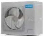 |
| MDUO18048060 | 208/230V-1Ph-60Hz | 810512032938 | 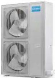 |
1.1.2 List of Indoor Units
| Model | Cooling/Heating Capacity (Btu/h) | Power Supply | Product Code | Appearance | |
| V/Ph/Hz | |||||
| Airhandler | MDUI18024 | 24000/24000 | 208/230V-1Ph-60Hz | 810512032945 | 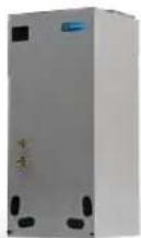 |
| Airhandler | MDUI18036 | 36000/36000 | 208/230V-1Ph-60Hz | 810512032969 | 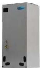 |
| Airhandler | MDUI18048 | 48000/48000 | 208/230V-1Ph-60Hz | 810512032976 |  |
| Airhandler | MDUI18060 | 54000/54000 | 208/230V-1Ph-60Hz | 810512032952 |  |
NOTE: 1 Ton = 12000Btu/h = 3.517kW
1.2 Electrical Parameters
| Model | Power supply | Circuit breaker capacity |
| V/Ph/Hz | A | |
| MDUO18024036 | 208/230V-1Ph-60Hz | 35 |
| MDUO18036048 | 208/230V-1Ph-60Hz | 45 |
| Model | Power Supply | Fuse Capacity | Circuit Breaker Capacity |
| V/Ph/Hz | A | A | |
| MDUI18024 | 208/230V-1Ph-60Hz | 3.15 | 15 |
| MDUI18036 | 208/230V-1Ph-60Hz | 3.15 | 15 |
| MDUI18048 | 208/230V-1Ph-60Hz | 3.15 | 15 |
| MDUI18060 | 208/230V-1Ph-60Hz | 3.15 | 15 |
2 Control
2.1 Operation Mode
2.1.1 Cooling Mode
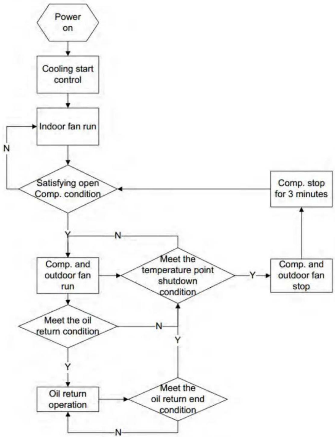
flowchart
graph TD
    A["Power on"] --> B["Cooling start control"]
    B --> C["Indoor fan run"]
    C --> D{Satisfying open Comp. condition}
    D -->|N| C
    D -->|Y| E["Comp. and outdoor fan run"]
    E --> F{Meet the oil return condition}
    F -->|Y| G["Oil return operation"]
    F -->|N| H{Meet the temperature point shutdown condition}
    H -->|Y| I["Comp. and outdoor fan stop"]
    I --> J["Comp. stop for 3 minutes"]
    J --> K{Meet the oil return end condition}
    K -->|N| C
    K -->|Y| L["End"]
2.1.2 Heating Mode
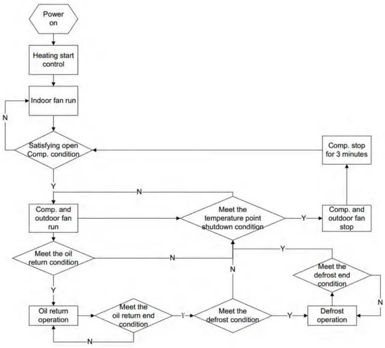
flowchart
graph TD
    A["Power on"] --> B["Heating start control"]
    B --> C["Indoor fan run"]
    C --> D{Satisfying open Comp. condition}
    D -->|N| C
    D -->|Y| E["Comp. and outdoor fan run"]
    E --> F{Meet the oil return condition}
    F -->|Y| G["Oil return operation"]
    F -->|N| H{Meet the temperature point shutdown condition}
    H -->|Y| I["Comp. and outdoor fan stop"]
    H -->|N| J{Meet the defrost end condition}
    J -->|Y| K["Defrost operation"]
    J -->|N| L["Comp. stop for 3 minutes"]
    L --> M["End"]
    E --> N{Meet the oil return end condition}
    N -->|Y| O{Meet the defrost condition}
    O -->|Y| P["End"]
    O -->|N| Q["End"]
2.2 Control Mode
2.2.1 Based Control
2.2.1.1 Compressor Control
When cooling or heating mode is turned on, indoor fan will run for a while before the compressor starts. Under different modes, the compressor can only be stopped after running for some time (special cases excluded). This is to protect the compressor from frequent start or stop. Once the compressor is stopped, it must not be restarted right away. Please wait for a few minutes.
2.2.1.2 EXV Control
When the unit is first started, the electronic expansion valve will reset control. During the process, the expansion valve will produce rattling sound. When cooling or heating mode is turned on, the valve will be open at a certain step before the compressor starts.
2.2.1.3 Outdoor Fan Control
This series air conditioner has two types of outdoor units: one with a single fan and the other with double fans. The outdoor fan can run at the highest level 10 and the lowest level 1. By controlling the speed of outdoor fan, the unit can achieve cooling at low temperature and heating at high temperature. In fan mode, outdoor fan will not work.
2.2.1.4 4-way Valve Control
After heating mode is turned on for a while, 4-way valve will be energized to change the direction of refrigerant flow so that the system can run in heating and the indoor unit will not blow cold air. Under other modes, the valve will not be energized.
To avoid the 4-way valve from incorrectly changing directions, when the unit stops in heating, due to a temperature point or other protection reasons, the 4-way valve will continue to function temporarily and lose power after a while.
There must be adequate differential pressure for the 4-way valve to change directions.
2.2.2 Special Control
2.2.2.1 Defrosting Control
ODU defrosting control in heating: Defrosting will start when the temperature sensed by outdoor tube temperature sensor reaches a preset value. During defrosting, the 4-way valve will switch to the cooling condition,
and outdoor and indoor fan will both stop. When the temperature sensed by outdoor tube temperature sensor reaches the preset value of defrosting stop, system will quit defrosting. The 4-way valve will switch back to the heating condition, compressor and outdoor unit fan restart.
2.2.2.2 Oil Return Control
If the unit is running at low frequency for a long time, system will enable oil return control. This is to lead oil in the pipeline back to the compressor so that the compressor will not be lack of oil. Generally, the oil return takes about 5min. The compressor running frequency will be raised to the preset oil return frequency.
2.2.3 Protection Control
2.2.3.1 High Pressure Protection Control
System will enable high pressure protection control if the high pressure switch is detected open for continuously a little time. Under high pressure protection, system will be shut down and display error code E1.
When high pressure protection occurs for the first time, system will restore operation if the high pressure switch is detected to be reclosed for continuously a little time. When high pressure protection occurs for the second time in a certain time period, system will not restore operation. You need to manually turn off the unit and clear the error before restarting up the unit. (If high pressure protection occurs frequently, please send for professional personnel to repair.)
2.2.3.2 Low Pressure Protection Control
System will enable low pressure protection control if the low pressure switch is detected open for continuously a little time. Under low pressure protection, system will be shut down and display error code E3. When low pressure protection occurs, system will restore operation if the low pressure switch is detected to be reclosed within a few minutes after shutdown. If low pressure protection occurs for several times in a period of time, system will not restore operation automatically. You need to manually turn off the unit before restarting up the unit.
2.2.3.3 High Temperature Prevention Control
Under heating mode, system will enable high temperature prevention control if the temperature sensed by indoor tube temperature sensor reaches a certain value. When high temperature prevention control is enabled, outdoor fan will slow down.
2.2.3.4 Discharge High Temperature Protection Control
System will enable discharge temperature protection control if the discharge high temperature sensor is
detected open for continuously a little time. Under discharge high temperature protection, system will be shut down and display error code E4. When discharge high temperature protection occurs, system will restore operation if the discharge high temperature sensor is detected to be reclosed within a few minutes after shutdown. If discharge high temperature protection occurs for several times in a period of time, system will not restore operation automatically. You need to manually turn off the unit before restarting up the unit.
2.3 Functions
2.3.1 Set Capacity Dip Switch
Set the capacity of the outdoor unit through the four dip switches of the outdoor unit main control board. Specific dip switch definition, the first dip switch distinguishes the capacity.
| Capacity | 24K | 36K | 48K | 60K |
| Dip Switches | 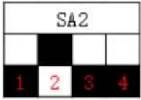 | 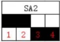 | 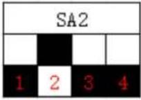 | 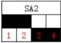 |
2.3.2 Set Defrost Mode
The second dip switch is selecting the defrost mode.
The second dip switch is used to change the defrost setting, factory default setting is standard defrost. Under extremely low environment temperature, if the standard defrost cannot have the condenser defrosted completely, please set the second dip switch to be strong defrost. Under strong defrost, the defrosting time will be longer, which enable the condenser to be defrosted completely.
| Defrost mode | Outdoor unit dip switches |
| Standard Defrost(Default) | 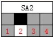 |
| Strong Defrost | 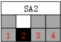 |
2.3.3 Set Operating Mode
The third dip switch and the fourth dip switch are selecting the operating mode. Standard mode is the conventional mode.
By setting the strong mode dip switches of the condensing unit, the air conditioner can quickly increase the capacity output and ensure reliable operation in a short time, so as to meet the user's demand for the indoor temperature to quickly reach the set temperature.
Energy saving mode is achieved by setting the condensing unit operating mode to operate the air conditioner within a small load range.
| Operating mode | Outdoor unit dip switches |
| Standard mode (Default) | 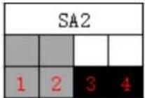 |
| Strong mode | 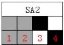 |
| Energy saving mode | 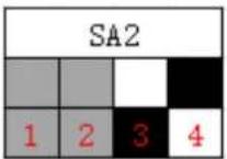 |
2.3.4 Set Indoor Fan Speed
Set the indoor fan speed through the eight dip switches of the indoor main control board. The higher level, the higher speed of the indoor unit fan.
| Capacity | 24K indoor unit dip switches | 36K indoor unit dip switches | ||
| Level 1(Default) | 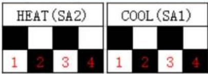 | 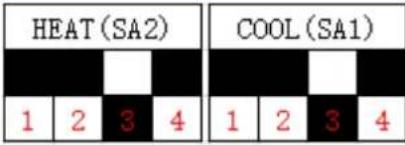 | ||
| Level 2 | 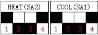 | 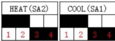 | ||
| Level 3 | 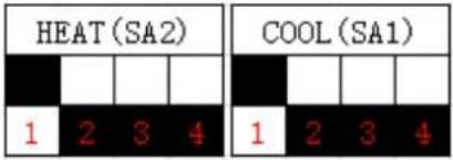 | 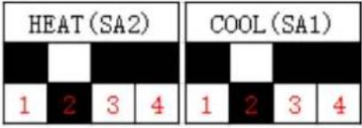 | ||
| Capacity | 48K indoor unit dip switches | 60K indoor unit dip switches |
| Level 1(Default) | 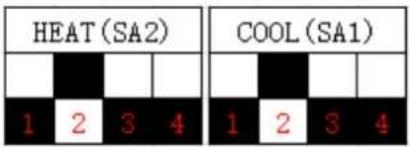 | 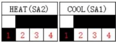 |
| Level 2 | 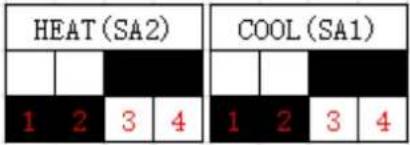 | 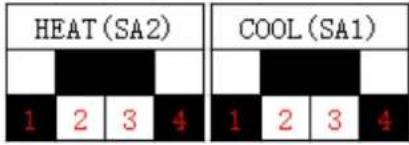 |
| Level 3 | 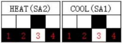 | 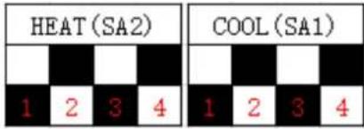 |
2.3.5 Forced Defrost Control
Press and hold "SW1" for about 5s to enter the first level menu of the debugging mode, the outdoor unit mainboard LED displayer flashes. Under the first level menu, short press "SW1" to switch various functions. After switching to "06", short press "SW2" or "SW3" to enter the forced defrosting mode, "ON" means open, "OF" means close, and then short press "SW1" to save. During debugging, if no operation is performed within 10s, the debugging mode interface will be exited.
2.3.6 Refrigerant Recovery Control
Press and hold "SW1" for about 5s to enter the first level menu of the debugging mode, the outdoor unit mainboard LED displayer flashes. Under the first level menu, short press "SW1" to switch various functions. After switching to "08", short press "SW2" or "SW3" to enter the refrigerant recovery control mode, "ON" means open, "OF" means close. And then short press "SW1" to save. During debugging, if no operation is performed within 10s, the debugging mode interface will be exited.
2.3.7 Forced Operation Control
Press and hold "SW1" for about 5s to enter the first level menu of the debugging mode, the outdoor unit mainboard LED displayer flashes. Under the first level menu, short press "SW1" to switch various functions. After
switching to "09", short press "SW2" or "SW3" to enter the forced operation control mode, "01" denotes that turn on the forced operation cooling mode; "02" denotes that turn on the forced operation cooling mode; "OF" indicates that shut down the forced cooling / heating mode. And then short press "SW1" to save. During debugging, if no operation is performed within 10s, the debugging mode interface will be exited.
2.3.8 Thermostat Functions
Thermostat model: XE70-00/E1, please refer to the thermostat instruction manual for all functions.
3 Troubleshooting
3.1 Wiring Diagrams
The following electric diagram is for reference only. Please refer to diagram sticked on the unit as the latest version.
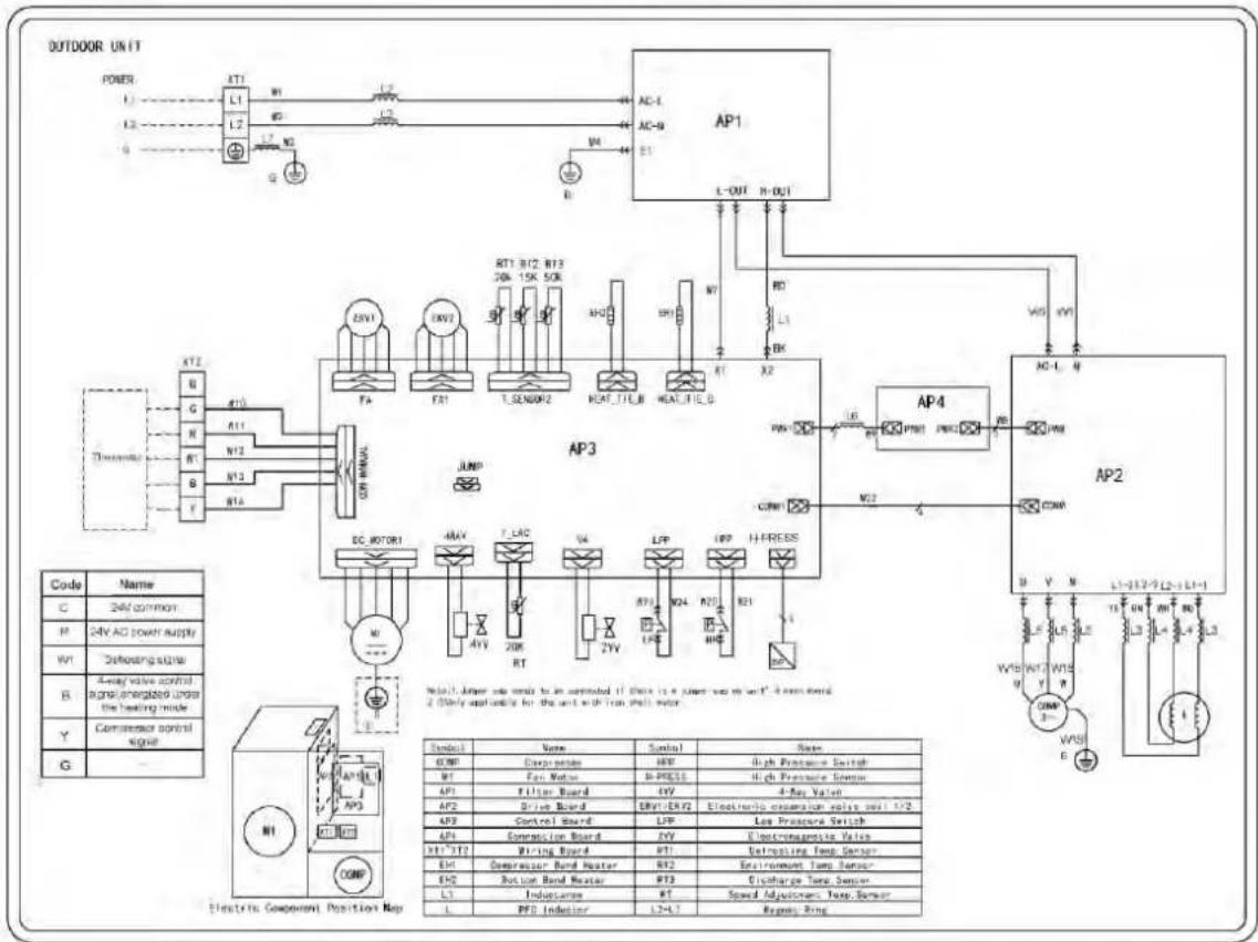
3.1.1 Wiring Diagrams for OUTDOOR UNITS
Model: MDUO18024036
flowchart
graph TD
    subgraph OUTDOOR_UNIT
        POWER["POWER"] --> L1["L1"]
        L2["L2"] --> L2
        L3["L3"] --> L3
        L4["L4"] --> L4
        L5["L5"] --> L5
        L6["L6"] --> L6
        L7["L7"] --> L7
        L8["L8"] --> L8
        L9["L9"] --> L9
        L10["L10"] --> L10
        L11["L11"] --> L11
        L12["L12"] --> L12
        L13["L13"] --> L13
        L14["L14"] --> L14
        L15["L15"] --> L15
        L16["L16"] --> L16
        L17["L17"] --> L17
        L18["L18"] --> L18
        L19["L19"] --> L19
        L20["L20"] --> L20
        L21["L21"] --> L21
        L22["L22"] --> L22
        L23["L23"] --> L23
        L24["L24"] --> L24
        L25["L25"] --> L25
        L26["L26"] --> L26
        L27["L27"] --> L27
        L28["L28"] --> L28
        L29["L29"] --> L29
        L30["L30"] --> L30
        L31["L31"] --> L31
        L32["L32"] --> L32
        L33["L33"] --> L33
        L34["L34"] --> L34
        L35["L35"] --> L35
        L36["L36"] --> L36
        L37["L37"] --> L37
        L38["L38"] --> L38
        L39["L39"] --> L39
        L40["L40"] --> L40
        L41["L41"] --> L41
        L42["L42"] --> L42
        L43["L43"] --> L43
        L44["L44"] --> L44
        L45["L45"] --> L45
        L46["L46"] --> L46
        L47["L47"] --> L47
        L48["L48"] --> L48
        L49["L49"] --> L49
        L50["L50"] --> L50
        AP1["AP1"] --> FA["FA"]
        AP2["AP2"] --> FAN["FAN"]
        AP3["AP3"] --> TSENOM["TESENOM"]
        AP4["AP4"] --> HEAT_TIC_B["HEAT_TIC_B"]
        AP5["AP5"] --> HEAT_FIE_D["HEAT_FIE_D"]
    end

    subgraph OUTDOOR_UNIT
        POWER_Power["POWER"]
        Power_LPower["Power"]
        Power_LPower_LPower["Power"]
        Power_LPower_LPower_LPower["Power"]
    end

    subgraph OUTDOOR_UNIT
        POWER_Power["Power"]
        Power_LPower_LPower_LPower["Power"]
    end

    subgraph OUTDOOR_UNIT
        POWER_Power_Rates["Power"]
        Power_LPower_Rates["Power"]
    end

    subgraph OUTDOOR_UNIT
        POWER_Power_Solar["Solar"]
        POWER_LPower_Solar_Solar["Power"]
    end

    subgraph OUTDOOR_UNIT
        POWER_Power_Tek["Sink"]
        POWER_LPower_Tek_Sink["Power"]
    end

    subgraph OUTDOOR_UNIT
        POWER_Power_Tek_Rates["Power"]
        POWER_LPower_Tek_Rates["Power"]
    end

    subgraph OUTDOOR_UNIT
        POWER_Power_Solar_Solar["Solar"]
        POWER_LPower_Solar_Solar["Power"]
    end

    subgraph OUTDOOR_UNIT
        POWER_Power_Tek_Rates["Power"]
        POWER_LPower_Tek_Rates["Power"]
    end

    subgraph OUTDOOR_UNIT
        POWER_Power_Solar_Solar_Solar["Solar"]
    end

    subgraph OUTDOOR_UNIT
        POWER_Power_Tek_Rates["Power"]
        POWER_LPower_Tek_Rates["Power"]
    end

    subgraph OUTDOOR_UNIT
        POWER_Power_Solar_Solar_Solar_Solar["Solar"]
    end

    subgraph OUTDOOR_UNIT
        POWER_Power_Tek_Rates["Power"]
        POWER_LPower_Tek_Rates["Power"]
    end

    subgraph OUTDOOR_UNIT
        POWER_Power_Solar_Solar_Solar_Solar_Solar["Solar"]
    end

    subgraph OUTDOOR_UNIT
        POWER_Power_Tek_Rates["Power"]
        POWER_LPower_Tek_Rates["Power"]
    end

    subgraph OUTDOOR_UNIT
        POWER_Power_Solar_Solar_Solar_Solar_Solar_Solar["Solar"]
    end

    subgraph OUTDOOR_UNIT
        POWER_Power_Tek_Rates["Power"]
        POWER_LPower_Tek_Rates["Power"]
    end

    subgraph OUTDOOR_UNIT
        POWER_Power_Solar_Solar_Solar_Solar_Solar_Solar_Solar["Solar"]
    end

    subgraph OUTDOOR_UNIT
        POWER_Power_Tek_Rates["Power"]
        POWER_LPower_Tek_Rates["Power"]
    end

    subgraph OUTDOOR_UNIT
        POWER_Power_Solar_Solar_Solar_Solar_Solar_Solar_Solar_Solar["Solar"]
    end

    subgraph OUTDOOR_UNIT
        POWER_Power_Tek_Rates["Power"]
        POWER_LPower_Tek_Rates["Power"]
    end

    subgraph OUTDOOR_UNIT
        POWER_Power_Solar_Solar_Solar_Solar_Solar_Solar_Solar_Solar_Solar["Solar"]
    end

    subgraph OUTDOOR_UNIT
        POWER_Power_Tek_Rates["Power"]
        POWER_LPower_Tek_Rates["Power"]
    end

    subgraph OUTDOOR_UNIT
        POWER_Power_Solar_Solar_Solar_Solar_Solar_Solar_Solar_Solar_Solar_Solar["Solar"]
    end

    subgraph OUTDOOR_UNIT
        POWER_Power_Tek_Rates["Power"]
        POWER_LPower_Tek_Rates["Power"]
    end

    subgraph OUTDOOR_UNIT
        POWER_Power_Solar_Solar_Solar_Solar_Solar_Solar_Solar_Solar_Solar_Solar_Solar["Solar"]
    end

    subgraph OUTDOOR_UNIT
        POWER_Power_Tek_Rates["Power"]
        POWER_LPower_Tek_Rates["Power"]
    end

    subgraph OUTDOOR_UNIT
        POWER_Power_Solar_Solar_Solar_Solar_Solar_Solar_Solar_Solar_Solar_Solar_Solar["Solar"]
    end
</details>
Model: MDUO18048060

<details>
<summary>text_image</summary>
Outdoor unit
Power
XT1
L1
L2
L3
3
0
AC-L
N-OUT1
L-OUT-N-OUT
AP1
DE-RS
L-OUT1
AP1
DC-MOTOR1
L-OUT1
L-OUT-N-OUT
AC-L
N-OUT1
L-OUT-N-OUT
AC-L
N-OUT1
L-OUT-N-OUT
AC-L
N-OUT1
AC-L
N-OUT1
AC-L
N-OUT1
AC-L
N-OUT1
AC-L
N-OUT1
AC-L
N-OUT1
AC-L
N-OUT1
AC-L
N-OUT1
AC-L
N-OUT1
AC-L
N-OUT1
AC-L
N-OUT1
AC-L
N-OUT1
AC-L
N-OUT1
AC-L 5 6 7 8 9 10 11 12 13 14 15 16 17 18 19 20 21 22 23 24 25 26 27 28 29 30 31 32 33 34 35 36 37 38 39 40 41 42 43 44 45 46 47 48 49 50 51 52 53 54 55 56 57 58 59 60 61 62 63 64 65 66 67 68 69 70 71 72 73 74 75 76 77 78 79 80 81 82 83 84 85 86 87 88 89 90 91 92 93 94 95 96 97 98 99 100
AC-VI
R-VI
R-VI
R-VI
R-VI
R-VI
R-VI
R-VI
R-VI
R-VI
R-VI
R-VI
R-VI
R-VI
R-VI
R-VI
R-VI
R-VI
R-VI
R-VI
R-VI
R-VI
R-VI
R-VI
R-VI
R-VI
TJX2
TJX2
TJX2
TJX2
TJX2
TJX2
TJX2
TJX2
TJX2
TJX2
TJX2
TJX2
TJX2
TJX2
TJX2
TJX2
TJX2
TJX2
TJX2
TJX2
TJX1
TJX1
TJX1
TJX1
TJX1
TJX1
TJX1
TJX1
TJX1
TJX1
TJX1
TJX1
TJX1
TJX1
TJX1
TJX1
TJX1
TJX1
TJX1
TJX1
TJX0
TJX0
TJX0
TJX0
TJX0
TJX0
TJX0
TJX0
TJX0
TJX0
TJX0
TJX0
TJX0
TJX0
TJX0
TJX0
TJX0
TJX0
TJX0
TJX0
TJX1
TJX1
TJX1
TJX1
TJX1
TJX1
TJX1
TJX1
TJX1
TJX1
TJX1
TJX1
TJX1
TJX1
TJX1
TJX1
TJX1
TJX1
TJX0
TJXO0
TJXO0
TJXO0
TJXO0
TJXO0
TJXO0
TJXO0
TJXO0
TJXO0
TJXO0
TJXO0
TJXO0
TJXO0
TJXO0
TJXO0
TJXO0
TJXO0
</details>
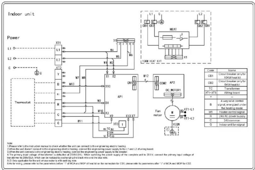
<h1 id="312-wiring-diagrams-of-indoor-units">3.1.2 Wiring Diagrams of INDOOR UNITS</h1>
Model: MDUI18024, MDUI18036

<details>
<summary>flowchart</summary>
```mermaid
graph TD
subgraph Power
L1["L1"] --> X1["XT1"]
L2["L2"] --> X2["XT2"]
G["G"] --> X3["XT3"]
Y["Y"] --> X4["X4"]
B["B"] --> X5["X5"]
#1["R"] --> X6["X6"]
R["G"] --> X7["X7"]
C["C"] --> X8["X8"]
G["G"] --> X9["X9"]
X1 --> W1["W1"]
X2 --> W2["W2"]
X3 --> W3["W3"]
X4 --> W4["W4"]
X5 --> W5["W5"]
X6 --> W6["W6"]
X7 --> W7
X8 --> W8
X9 --> W9
X10 --> W10
X11 --> W11
X12 --> W12
W1 --> X1["XT1-L1"]
W2 --> X2["XT2-L2"]
W3 --> X3["XT3-L3"]
W4 --> X4["XT4-L4"]
W5 --> X5["XT5-L5"]
W6 --> X6["XT6-L6"]
end
subgraph Thermostat
Y["Y"] --> X1
B["B"] --> X2
#1["R"] --> X3
R["G"] --> X4
C["C"] --> X5
G["G"] --> X6
end
subgraph Motor
AP1["X10"] --> AP2["X11"]
AP1 --> COM2["COM2"]
AP1 --> M["MC Motor1"]
AP1 --> XT1-XT3["XT1-XT3"]
AP1 --> XT1-XT7["XT1-XT7"]
AP1 --> XT1-XT8["XT1-XT8"]
AP1 --> XT1-XT9["XT1-XT9"]
AP1 --> XT1-XT10["XT1-XT10"]
AP1 --> XT1-XT11["XT1-XT11"]
AP1 --> XT1-XT12["XT1-XT12"]
end
subgraph Fan motor
M["M"] --> BD["BD"]
BD --> XT1-XTL["XT1-L1"]
BD --> BK["BK"]
BK --> XT1-XTL
MT["MT"] --> YEGN["YEGN"]
YEGN --> G["G"]
end
Note:
1. Please refer to the instruction manual to check whether the unit can connect to the engineering electric heating.
2. When the unit doesn't connect to the engineering electric heating, connect the engineering power supply to the L1 and L2 of wiring board.
3. When the unit connects to the engineering electric heating, connect the engineering power supply to the breaker.
4. The primary input voltage of transformer is defaulted at 230V(BK). When switching the power supply of the complete unit to 208V, connect the primary input voltage of transformer to 208V(BU), which can be realized by exchanging the black wire and the blue wire.
5. Only applicable for the unit whose motor is with earthing wire.
Legend:
Code: CB1 = Circuit breaker, TC = Transformer, XT1-XT3 = Wiring board, Y = -, B = 4-way valve control signal, VW = Heater control signal, R = 24V AC power supply, C = 24V common, G = Indoor unit fan signal.
Model: MDUI18048, MDUI18060
3.2 PCB Layout
3.2.1 Interface
Indoor unit:
Model: MDUI18024, MDUI18036, MDUI18048, MDUI18060 Mainboard
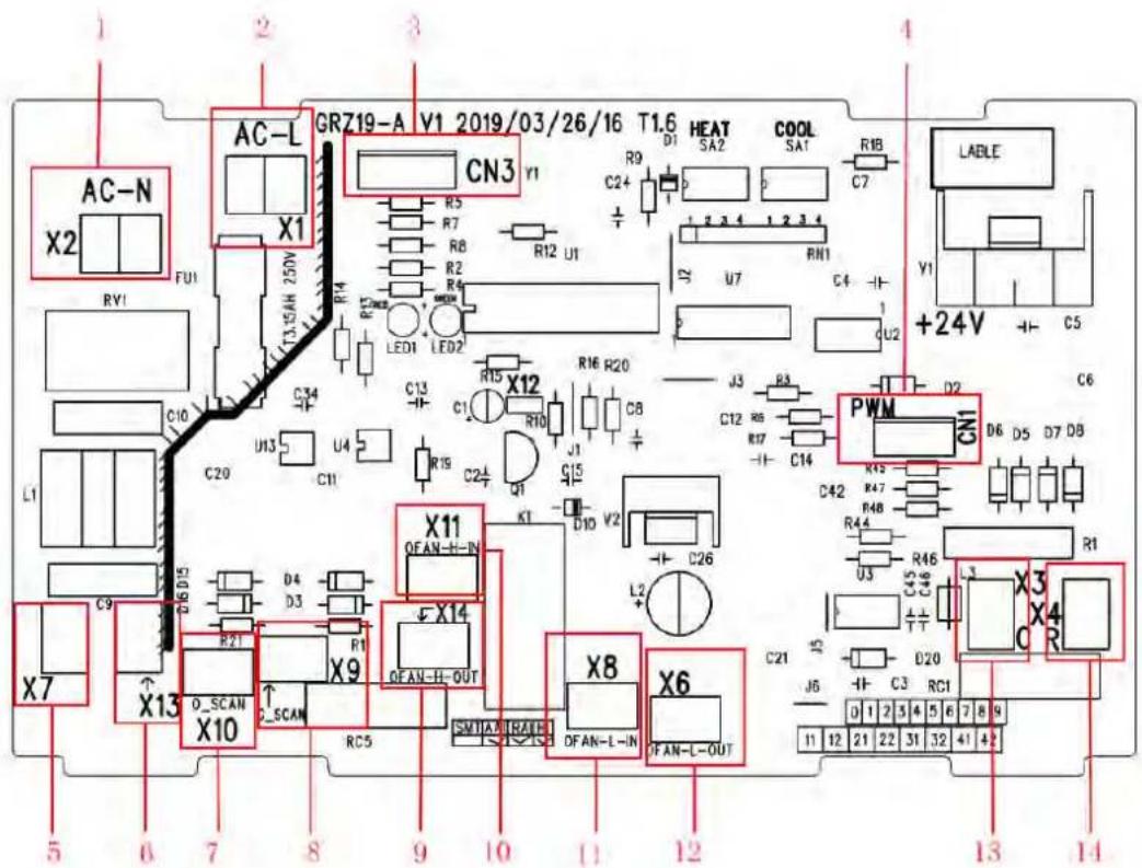
| No. | Printing | Interface | No. | Printing | Interface |
| 1 | AC-N (X2) | Neutral wire input | 8 | X9(G_SCAN) | Indoor motor check |
| 2 | AC-L (X1) | Live wire input | 9 | X14(OFAN-H-OUT) | AC motor high speed output |
| 3 | CN3 | Wired control communication interface | 10 | X11(OFAN-H-IN) | AC motor high speed input |
| 4 | CN1 | DC motor output | 11 | X8(OFAN-L-IN) | AC motor low speed input |
| 5 | X7 | Transformer Neutral wire input | 12 | X6(OFAN-L-OUT) | AC motor low speed output |
| 6 | X13 | Transformer Live wire input | 13 | X3(C) | Transformer Neutral wire output |
| 7 | X10(O_SCAN) | 4-Way check | 14 | X4(R) | Transformer Live wire output |
Pinboard
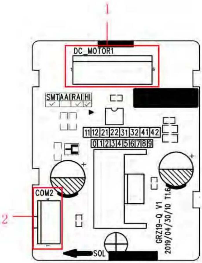
| No. | Printing | Interface | No. | Printing | Interface |
| 1 | DC-MOTOR1 | DC motor output | 2 | COM2 | DC motor control signal input |
Outdoor unit:
Model: MDUO18024036, MDUO18048060
Mainboard
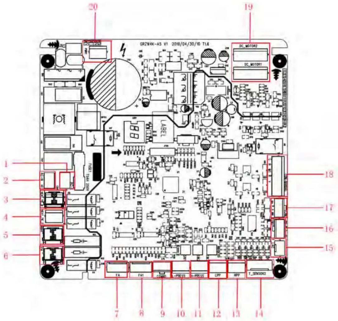
| No. | Printing | Interface | No. | Printing | Interface |
| 1 | AC-L | Live wire input | 11 | H-PRESS | High pressure sensor interface |
| 2 | AC-N | Neutral wire input | 12 | LPP | System low pressure protection interface |
| 3 | HEAT_TIE_B | Chassis electric heating belt | 13 | HPP | System high pressure protection interface |
| 4 | HEAT_TIE_C | Compressor electric heating belt | 14 | T_SENSOR2 | 2. Outdoor tube temperature sensor interface4. Outdoor ambient temperature sensor interface6. Discharge temperature sensor interface |
| 5 | 4WAY | 4-way valve | 15 | T_LAC | Low temperature cooling temperature sensing |
| 6 | VA | Electromagnetic valve interface | 16 | COM7 | Unit communication interface |
| 7 | FA | Electronic expansion valve interface | 17 | CN6 | GPRS communication interface |
| 8 | FA1 | Electronic expansion valve 1 interfaceRefrigerant heat dissipation | 18 | COM-MANUAL | Thermostat interface |
| 9 | COMM1 | Drive communication interface | 19 | DC_MOTOR1DC_MOTOR2 | DC motor output |
| 10 | L-PRESS | Low pressure sensor interface | 20 | PWR1 | 310V DC power supply interface |
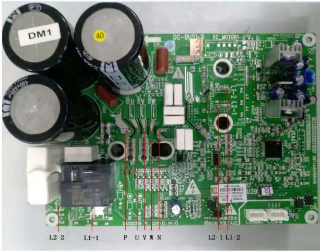
Drive Board:
Model: MDUO18024036
| No. | Printing | Interface | No. | Printing | Interface |
| 1 | L2-2 | PFC induction wire (blue) | 10 | P-OUT | Reserved |
| 2 | AC-L | Live wire | 11 | L1-2 | PFC induction wire (white) |
| 3 | L1-1 | PFC induction wire (brown) | 12 | L2-1 | PFC induction wire (yellow) |
| 4 | N | Neutral wire | 13 | G-OUT | Reserved |
| 5 | COMM1 | Communication terminal, same with COMM | 14 | U | Compressor U phase terminal |
| 6 | COMM | Communication terminal, same with COMM1 | 15 | V | Compressor V phase terminal |
| 7 | PWR | Drive power supply terminal | 16 | W | Compressor W phase terminal |
| 8 | DC-MOTOR1 | DC fan terminal | 17 | JTAG1 | Programming interface (for testing) |
| 9 | DC-BUS1 | Power discharge terminal (for testing) | - | - | - |
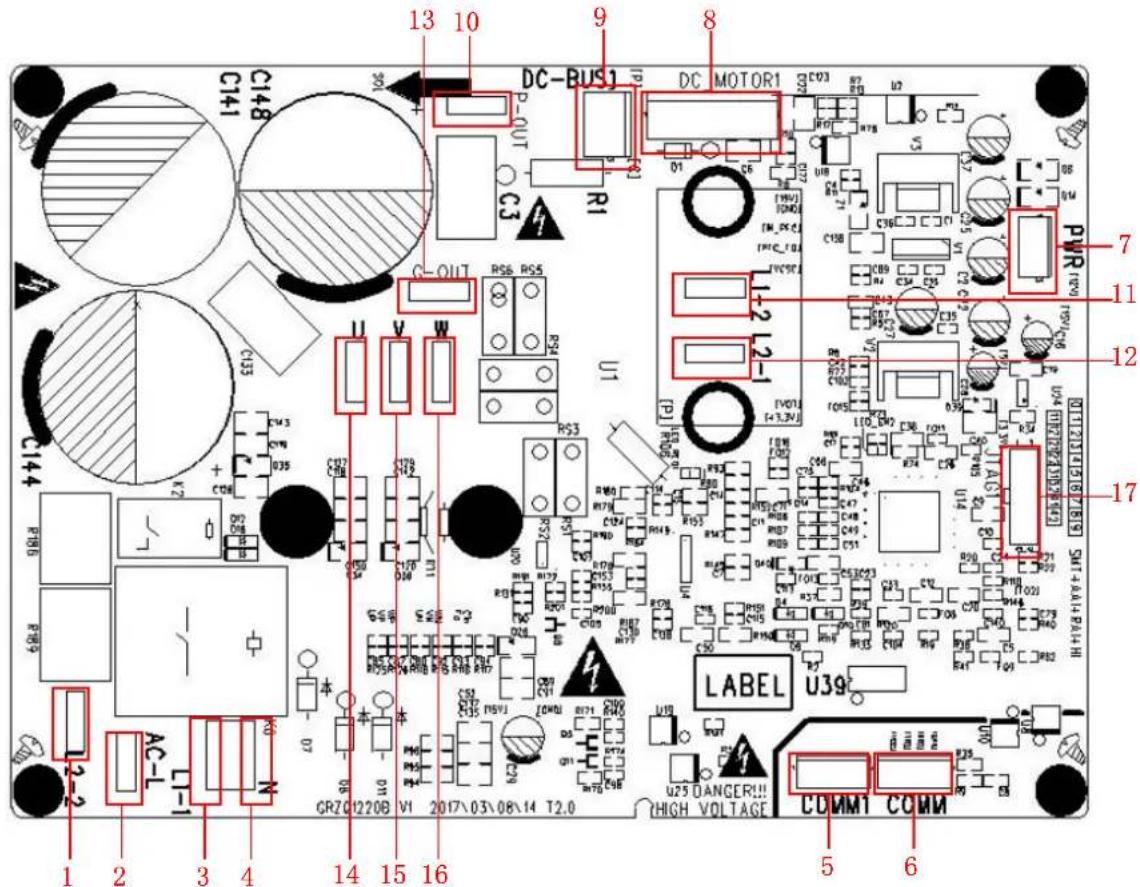
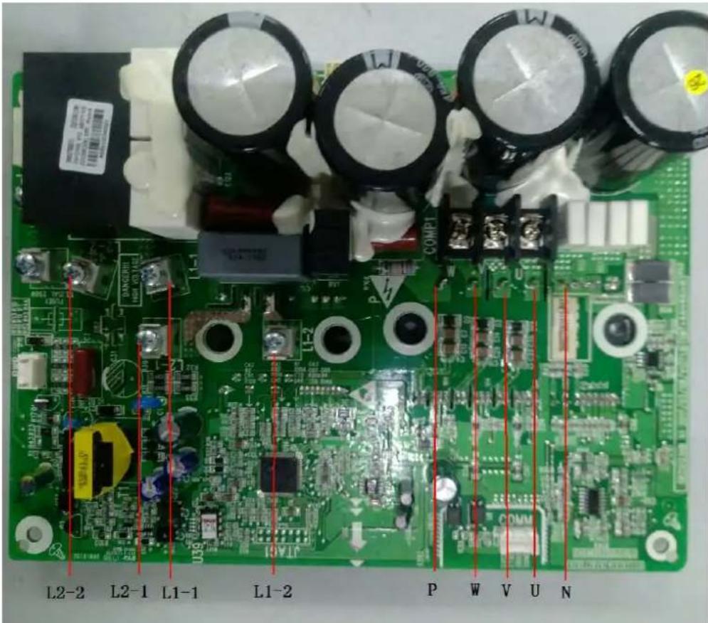
Model: MDUO18048060
| No. | Printing | Interface | No. | Printing | Interface |
| 1 | L2-2 | PFC induction wire (blue) | 8 | L1-2 | PFC induction wire (white) |
| 2 | AC-L | Live wire | 9 | U | Compressor U phase terminal |
| 3 | L1-1 | PFC induction wire (brown) | 10 | V | Compressor V phase terminal |
| 4 | N | Neutral wire | 11 | W | Compressor W phase terminal |
| 5 | JTAG1 | Programming interface (for testing) | 12 | PWR | Drive power supply terminal |
| 6 | COMM | Communication terminal, same with COMM | 13 | DC-BUS | Power discharge terminal (for testing) |
| 7 | L2-1 | PFC induction wire (yellow) | - | - | - |
Filtering Board:
Model: MDUO18024036
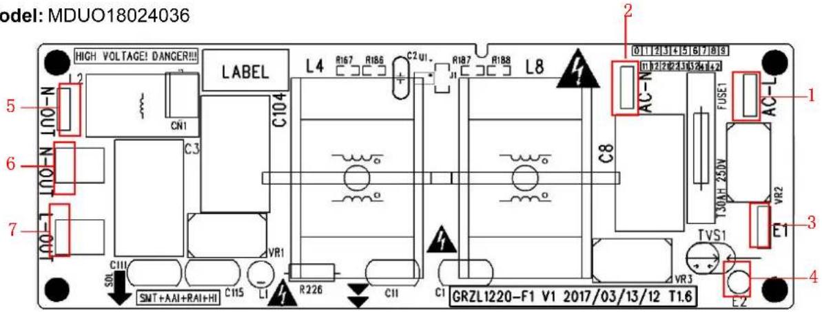
| No. | Printing | Interface | No. | Printing | Interface |
| 1 | AC-L | Power input live wire terminal | 5 | N-OUT | Power output neutral wire terminal (reserved) |
| 2 | AC-N | Power input neutral wire terminal | 6 | N-OUT | Power output neutral wire terminal |
| 3 | E1 | Filtering board ground wire terminal | 7 | L-OUT | Power output live wire terminal |
| 4 | E2 | Filtering board grounding hole (reserved) | - | - | - |
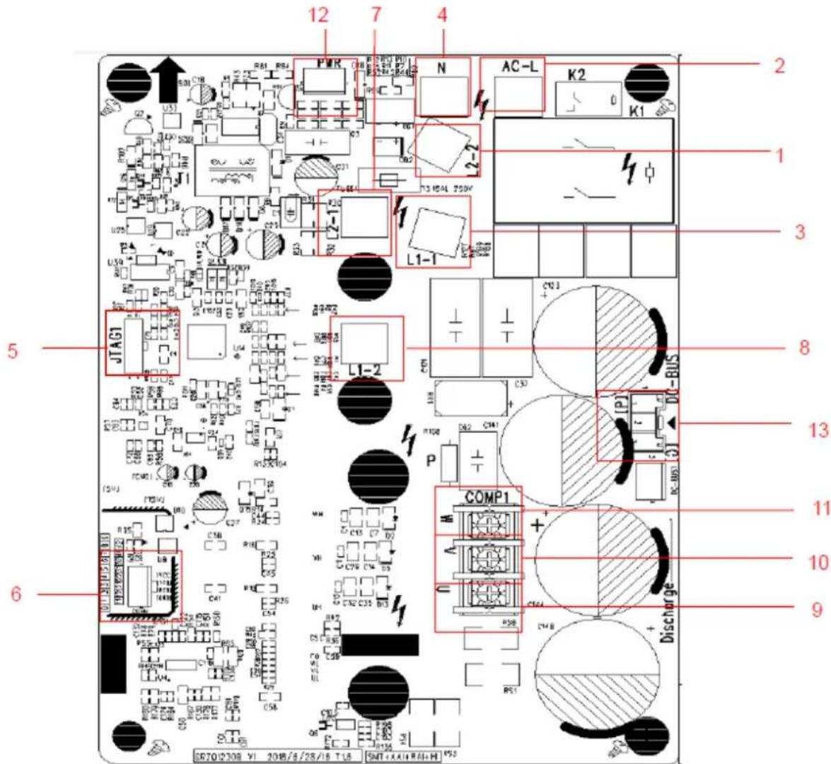
Model: MDUO18048060
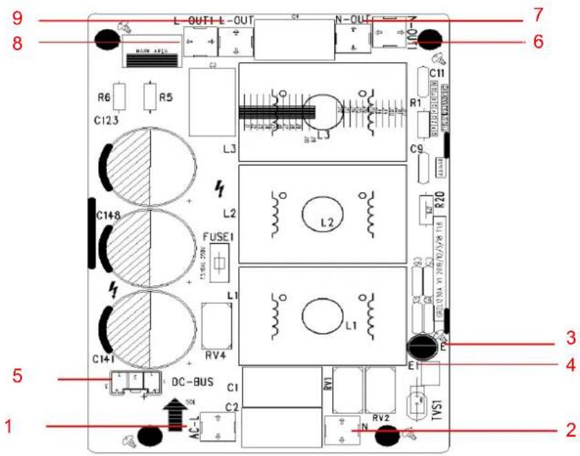
| No. | Printing | Interface | No. | Printing | Interface |
| 1 | AC-L | Power input live wire terminal | 6 | N-OUT1 | Power output neutral wire terminal (reserved) |
| 2 | N | Power input neutral wire terminal | 7 | N-OUT | Power output neutral wire terminal |
| 3 | E | Filtering board ground wire terminal | 8 | L-OUT1 | Power output live wire terminal |
| 4 | E1 | Filtering board grounding hole (reserved) | 9 | L-OUT | Power output live wire terminal |
| 5 | DC-BUS | Power discharge terminal (for testing) | - | - | - |
3.2.2 IPM, PFC Testing Method
3.2.2.1 Method of Testing IPM Module
(1) Preparation before test: prepare a universal meter and turn to its diode option, and then remove the wires U, V, W of the compressor after it is powered off for one minute.
(2) Testing Steps
Step 1: put the black probe on the place P and the red one on the wiring terminal U, V, W respectively as shown in the following figure to measure the voltage between UP, VP and WP.
Step 2: put the red probe on the place N and the black one on the wiring terminal U, V, W respectively as shown in the following figure to measure the voltage between NU, NV and NW.
(3) If the measured voltages between UP, VP, WP, NU, NV, NV are all among 0.3V-0.7V, then it indicates the IPM module is normal; If any measured valve is 0, it indicates the IPM is damaged.
3.2.2.2 Method of Testing PFC Module Short Circuit
(1) Preparation before test: prepare a universal meter and turn to its diode option, and then remove the wires L1-2, L2-1 after it is powered off for one minute.
(2) Testing Steps:
Step 1: Put the black probe on the place P and the red one on the wiring terminal L1-2, L2-1 respectively as shown in the following figure to measure the voltage between L1-2 and P; L2-1 and P.
Step 2: Put the red probe on the place N and the black one on the wiring terminal L1-2, L2-1 respectively as shown in the following figure to measure the voltage between N and L1-2; N and L2-1.
(3) If the measured voltages between L1-2 and P; L2-1 and P; N and L1-2; N and L2-1 are all among 0.3V-0.7V, then it indicates the PFC module is normal; If any measured valve is 0, it indicates the PFC is damaged.
MDUO18024036
MDUO18048060
3.3 Error Code
| No. | Error code | Error |
| 1 | E1 | Compressor high pressure protection |
| 2 | E3 | Compressor low pressure protection |
| 3 | E4 | Compressor air discharge high-temperature protection |
| 4 | F2 | Condenser temperature sensor error |
| 5 | F3 | Outdoor ambient temperature sensor error |
| 6 | F4 | Discharge temperature sensor error |
| 7 | F6 | ODU tube temperature sensor error |
| 8 | EE | ODU memory chip error |
| 9 | H4 | Overload |
| 10 | H5 | IPM protection |
| 11 | H6 | DC fan error |
| 12 | H7 | Driver out-of-step protection |
| 13 | HC | Pfc protection |
| 14 | Lc | Startup failure |
| 15 | P0 | Driver reset protection |
| 16 | P5 | Over-current protection |
| 17 | P6 | Master control and driver communication error |
| 18 | P7 | Driver module sensor error |
| 19 | P8 | Driver module high temperature protection |
| 20 | PA | AC current protection |
| 21 | Pc | Driver current error |
| 22 | PL | Bus low-voltage protection |
| 23 | PH | Bus high-voltage protection |
| 24 | PU | Charge loop error |
| 25 | ee | Drive memory chip error |
| 26 | e1 | High pressure sensor error |
| 27 | C4 | ODU jumper cap error |
If malfunction occurs during operation, LCD temperature display zone will show the failure information. If several malfunctions occur at the same time, their corresponding error codes will be shown in turn. When malfunction occurs, please shut off the unit and send for professional personnel to repair. For example, E1 (as shown below) indicates high pressure protection.
3.4 Troubleshooting
3.4.1 "E1" Compressor High Pressure Protection
Error display: ODU mainboard LED displayer
Error judgment condition and method:
It is judged through the action of high pressure switch. If the high pressure switch is cut off, it is judged that high pressure is too high and the system stops operation for protection.
Possible reason:
■Cut-off valve of ODU is not fully opened;
■High pressure switch is abnormal;
■Outdoor or indoor fan is not working properly;
■IDU filter or air duct is blocked (heating mode);
■Ambient temperature is too high;
■Refrigerant charging amount is too much;
■System pipeline is blocked
Troubleshooting:
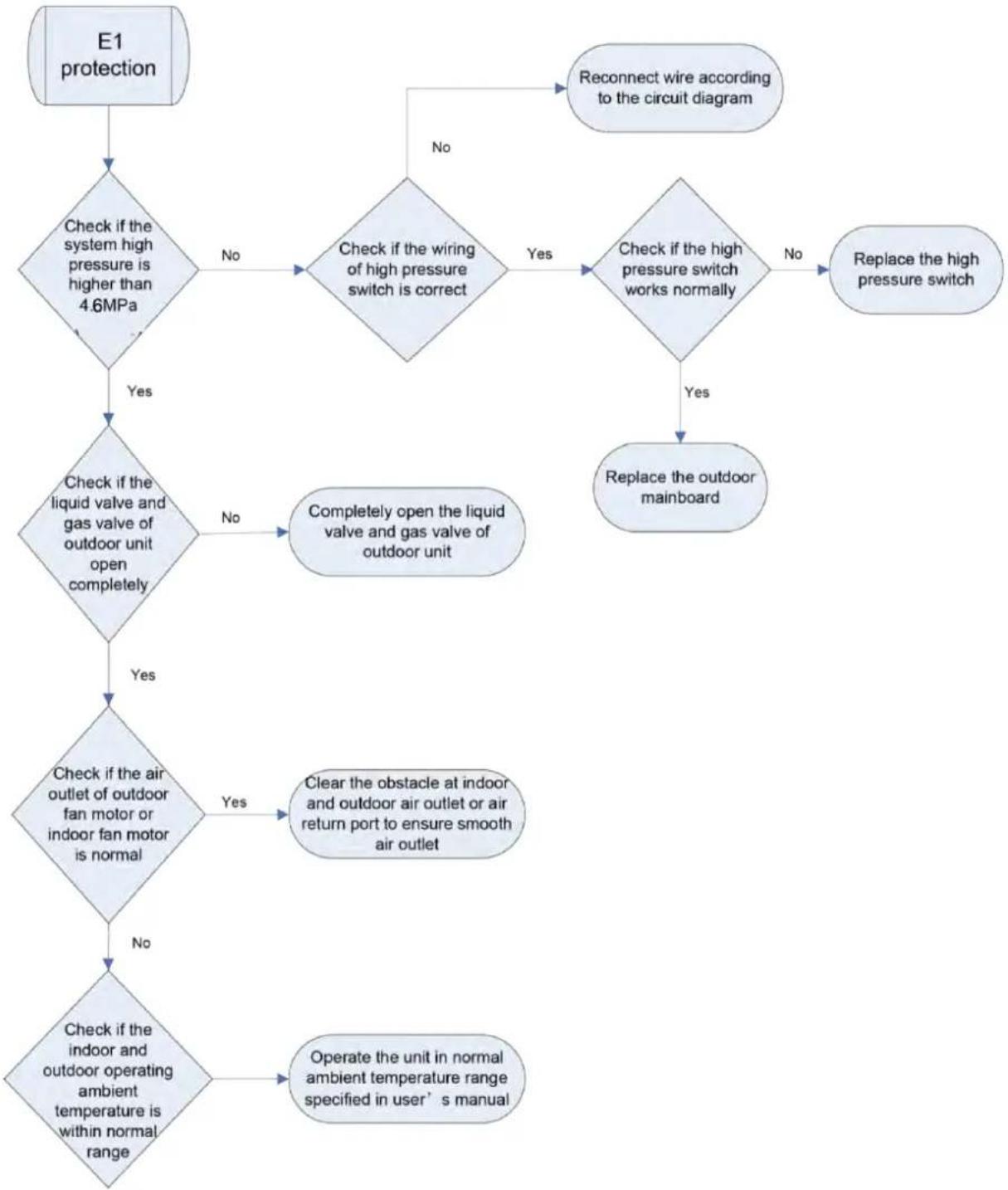
flowchart
graph TD
    A["E1 protection"] --> B{Check if the system high pressure is higher than 4.6MPa}
    B -->|No| C{Check if the wiring of high pressure switch is correct}
    C -->|Yes| D{Check if the high pressure switch works normally}
    D -->|No| E["Replace the high pressure switch"]
    D -->|Yes| F["Replace the outdoor mainboard"]
    B -->|Yes| G{Check if the liquid valve and gas valve of outdoor unit open completely}
    G -->|No| H["Completely open the liquid valve and gas valve of outdoor unit"]
    G -->|Yes| I{Check if the air outlet of outdoor fan motor or indoor fan motor is normal}
    I -->|Yes| J["Clear the obstacle at indoor and outdoor air outlet or air return port to ensure smooth air outlet"]
    I -->|No| K{Check if the indoor and outdoor operating ambient temperature is within normal range}
    K -->|No| L["Operate the unit in normal ambient temperature range specified in user's manual"]
    K -->|Yes| M["Reconnect wire according to the circuit diagram"]
3.4.2 "E3" Compressor Low-pressure Protection, Refrigerant Shortage
Protection, Refrigerant Recovery Mode
Error display: ODU mainboard LED displayer
Error judgment condition and method:
It is judged through the action of low pressure switch. If the low pressure switch is cut off, it is judged that low pressure is too low and the system stops operation for protection.
Possible reason:
■Cut-off valve of ODU is not fully opened;
■Low pressure sensor is abnormal;
■Outdoor or indoor fan is not working properly;
■IDU filter or air duct is blocked (cooling mode);
■Ambient temperature is too low;
■Refrigerant charging amount is insufficient;
■System pipeline is blocked;
Troubleshooting:
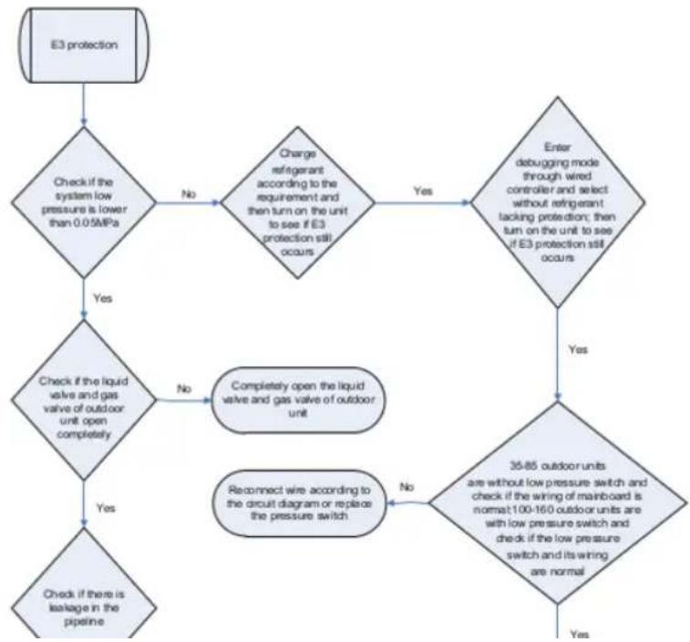
flowchart
graph TD
    A["E3 protection"] --> B{Check if the system low pressure is lower than 0.05MPa}
    B -->|No| C{Charge refrigerator according to the requirement and then turn on the unit to see if E3 protection still occurs}
    C -->|Yes| D["Enter debugging mode through wired controller and select without refrigerant lacking protection; then turn on the unit to see if E3 protection still occurs"]
    D -->|Yes| E{Check if the liquid valve and gas valve of outdoor unit open completely}
    E -->|No| F["Completely open the liquid valve and gas valve of outdoor unit"]
    F --> G{Reconnect wire according to the circuit diagram or replace the pressure switch}
    G -->|No| H{35-85 outdoor units are without low pressure switch and check if the wiring of mainboard is normal; 100-160 outdoor units are with low pressure switch and check if the low pressure switch and its wiring are normal}
    H -->|Yes| I["Check if there is leakage in the pipeline"]
Possible reason:
■Cut-off valve of ODU is not fully opened;
■Electronic expansion valve is abnormal;
■Outdoor or indoor fan is not working properly;
■IDU filter or air duct is blocked (cooling mode);
■Ambient temperature exceeds allowable operation range;
■Refrigerant charging amount is insufficient;
■System pipeline is blocked;
Troubleshooting:
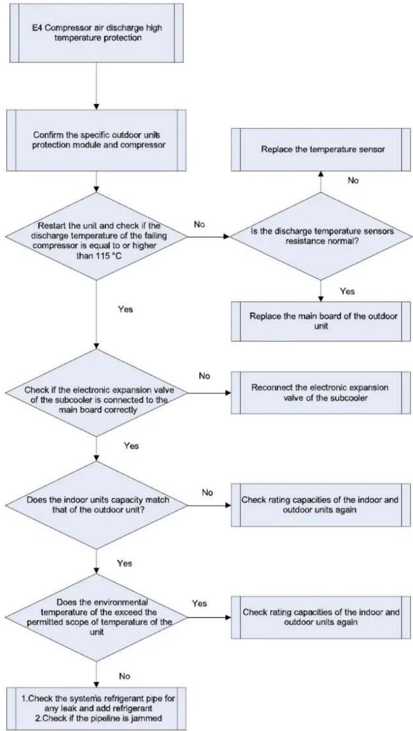
flowchart
graph TD
    A["E4 Compressor air discharge high temperature protection"] --> B["Confirm the specific outdoor units protection module and compressor"]
    B --> C{Restart the unit and check if the discharge temperature of the failing compressor is equal to or higher than 115 °C}
    C -->|No| D{Is the discharge temperature sensors resistance normal?}
    C -->|Yes| E{Replace the main board of the outdoor unit}
    D -->|No| F["Replace the temperature sensor"]
    D -->|Yes| G["Replace the main board of the outdoor unit"]
    E --> H{Is the discharge temperature sensors resistance normal?}
    H -->|No| I["Replace the main board of the outdoor unit"]
    H -->|Yes| J{Check if the electronic expansion valve of the subcooler is connected to the main board correctly}
    J -->|No| K["Reconnect the electronic expansion valve of the subcooler"]
    J -->|Yes| L{Does the indoor units capacity match that of the outdoor unit?}
    L -->|No| M["Check rating capacities of the indoor and outdoor units again"]
    L -->|Yes| N{Does the environmental temperature of the exceed the permitted scope of temperature of the unit}
    N -->|Yes| O["Check rating capacities of the indoor and outdoor units again"]
    N -->|No| P["1. Check the systemis refrigerant pipe for any leak and add refrigerant\n2. Check if the pipeline is jammed"]
3.4.4 "F2" Condenser Temperature Sensor Error
Error display: ODU mainboard LED displayer
Error judgment condition and method:
Sample the AD value of temperature sensor through temperature sensor detecting circuit and judge the range of AD value, If the sampling AD value exceeds upper limit and lower limit in 5 seconds continuously, report
the error.
Possible reason:
■Poor contact between temperature sensor and terminal in mainboard interface
■Temperature sensor is abnormal
■Detecting circuit is abnormal
Troubleshooting:
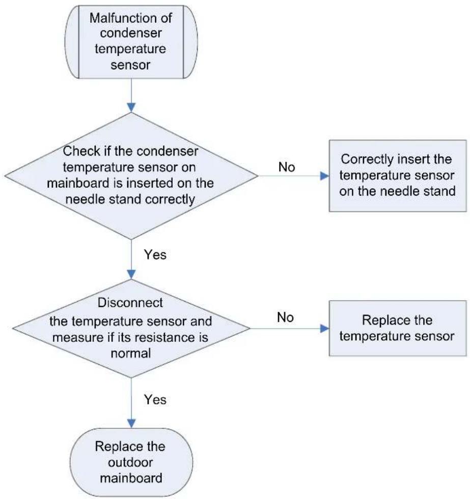
flowchart
graph TD
    A["Malfunction of condenser temperature sensor"] --> B{Check if the condenser temperature sensor on mainboard is inserted on the needle stand correctly}
    B -->|No| C["Correctly insert the temperature sensor on the needle stand"]
    B -->|Yes| D{Disconnect the temperature sensor and measure if its resistance is normal}
    D -->|No| E["Replace the temperature sensor"]
    D -->|Yes| F["Replace the outdoor mainboard"]
NOTE:
Please refer to Appendix 1 for the relation between temperature and resistance of temperature sensor.
3.4.5 "F3" Outdoor Ambient Temperature Sensor Error
Error display: ODU mainboard LED displayer
Error judgment condition and method:
Sample the AD value of temperature sensor through temperature sensor detecting circuit and judge the range of AD value, If the sampling AD value exceeds upper limit and lower limit in 5 seconds continuously, report the error.
Possible reason:
■Poor contact between ambient temperature sensor and terminal in mainboard interface
■Ambient temperature sensor is abnormal
■Detecting circuit is abnormal
Troubleshooting:
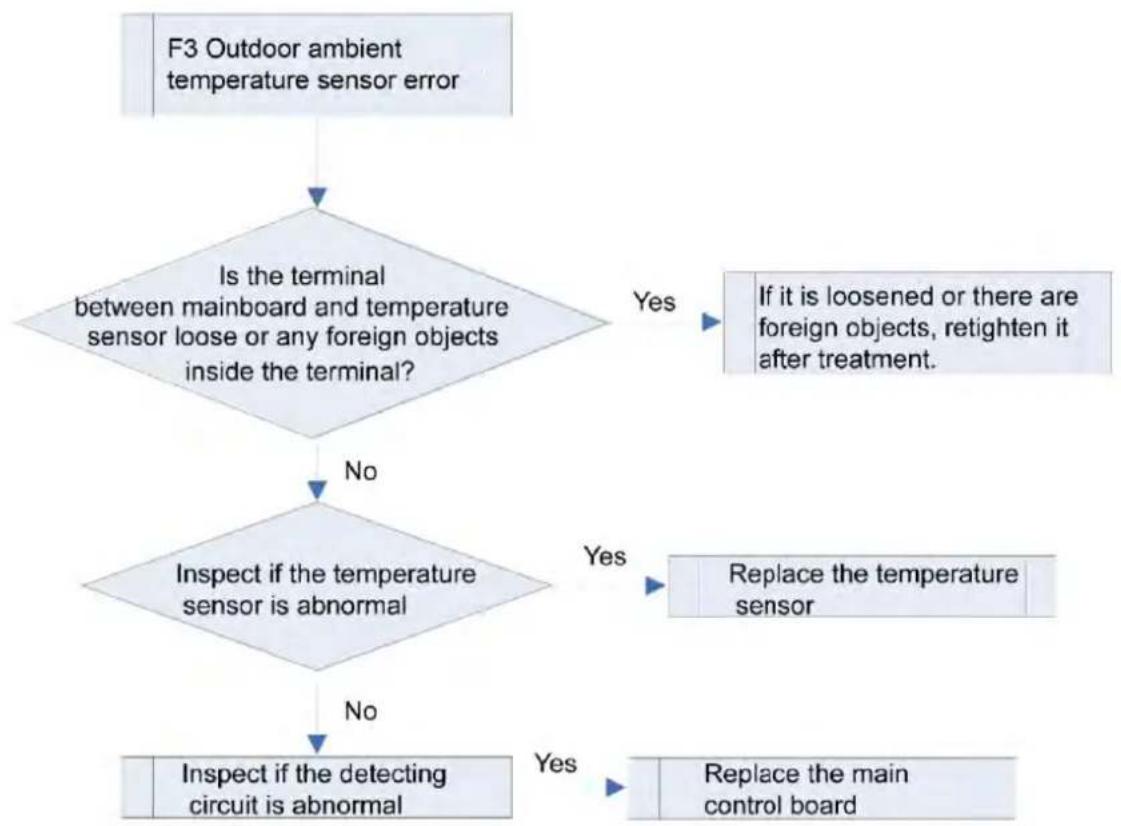
flowchart
graph TD
    A["F3 Outdoor ambient temperature sensor error"] --> B{Is the terminal between mainboard and temperature sensor loose or any foreign objects inside the terminal?}
    B -->|Yes| C["If it is loosened or there are foreign objects, retighten it after treatment."]
    B -->|No| D{Inspect if the temperature sensor is abnormal}
    D -->|Yes| E["Replace the temperature sensor"]
    D -->|No| F["Inspect if the detecting circuit is abnormal"]
    E --> G["Replace the main control board"]
    F --> H["Yes"]
NOTE:
Please refer to Appendix 1 for the relation between temperature and resistance of temperature sensor.
3.4.6 "F4" Discharge Temperature Sensor Error
Error display: ODU mainboard LED displayer
Error judgment condition and method:
Sample the AD value of temperature sensor through temperature sensor detecting circuit and judge the range of AD value, If the sampling AD value exceeds upper limit and lower limit in 5 seconds continuously, report the error.
Possible reason:
■Poor contact between temperature sensor and terminal in mainboard interface
■Temperature sensor is abnormal
■Detecting circuit is abnormal
Troubleshooting:
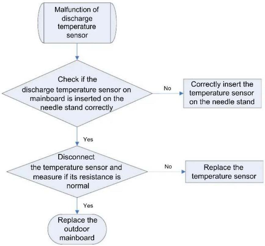
flowchart
graph TD
    A["Malfunction of discharge temperature sensor"] --> B{Check if the discharge temperature sensor on mainboard is inserted on the needle stand correctly}
    B -->|No| C["Correctly insert the temperature sensor on the needle stand"]
    B -->|Yes| D{Disconnect the temperature sensor and measure if its resistance is normal}
    D -->|No| E["Replace the temperature sensor"]
    D -->|Yes| F["Replace the outdoor mainboard"]
NOTE:
Please refer to Appendix 1 for the relation between temperature and resistance of temperature sensor.
3.4.7 "F6" ODU Tube Temperature Sensor Error
Error display: ODU mainboard LED displayer
Error judgment condition and method:
Sample the AD value of temperature sensor through temperature sensor detecting circuit and judge the range of AD value, If the sampling AD value exceeds upper limit and lower limit in 5 seconds continuously, report the error.
Possible reason:
■Poor contact between temperature sensor and terminal in mainboard interface
■Temperature sensor is abnormal
■Detecting circuit is abnormal
Troubleshooting:
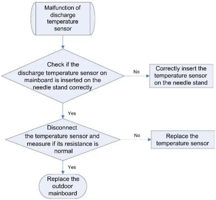
flowchart
graph TD
    A["Malfunction of discharge temperature sensor"] --> B{Check if the discharge temperature sensor on mainboard is inserted on the needle stand correctly}
    B -->|No| C["Correctly insert the temperature sensor on the needle stand"]
    B -->|Yes| D{Disconnect the temperature sensor and measure if its resistance is normal}
    D -->|No| E["Replace the temperature sensor"]
    D -->|Yes| F["Replace the outdoor mainboard"]
NOTE:
Please refer to Appendix 1 for the relation between temperature and resistance of temperature sensor.
3.4.8“EE” ODU Memory Chip Error
Error display: ODU mainboard LED displayer
Error judgment condition and method:
If ODU mainboard cannot read the memory chip, this error will be reported.
Possible reason:
■Memory chip on the ODU mainboard is damaged.
■Memory chip is weakly welded.
■Memory chip lead is short-circuited.
Troubleshooting:
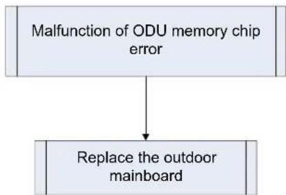
flowchart
graph TD
    A["Malfunction of ODU memory chip error"] --> B["Replace the outdoor mainboard"]
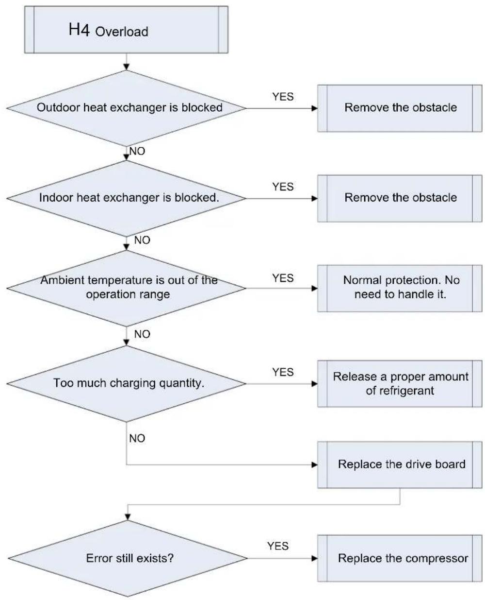
3.4.9 "H4" Overload
Error display: ODU mainboard LED displayer
Error judgment condition and method:
When condensing pressure is higher than the protection value, system will report overload protection.
Possible reason:
■Cooling ODU heat exchanger is blocked or heat exchange is bad.
■Heating IDU heat exchanger is blocked or heat exchange is bad.
■Operating temperature is too high.
■System charging quantity is too much.
Troubleshooting:
flowchart
graph TD
    A["H4 Overload"] --> B{Outdoor heat exchanger is blocked}
    B -->|YES| C["Remove the obstacle"]
    B -->|NO| D{Indoor heat exchanger is blocked.}
    D -->|YES| E["Remove the obstacle"]
    D -->|NO| F{Ambient temperature is out of the operation range}
    F -->|YES| G["Normal protection. No need to handle it."]
    F -->|NO| H{Too much charging quantity.}
    H -->|YES| I["Release a proper amount of refrigerant"]
    H -->|NO| J["Replace the drive board"]
    I --> K["Replace the compressor"]
    J --> L{Error still exists?}
    K --> L
    L -->|YES| M["End"]
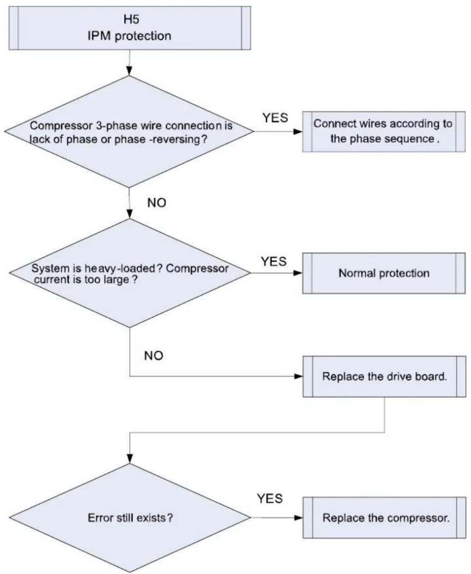
3.4.10 "H5" IPM Protection
Error display: ODU mainboard LED displayer
Error judgment condition and method:
When power is connected and drive chip received IPM lead F0 that is of low level, than it is IPM module malfunction. System will shut down for protection.
Possible reason:
■Compressor 3-phase wire connection is lack of phase or phase-reversed.
■System is overloaded and compressor current is too large.
■Drive board IPM module is damaged.
■Drive board IPM module's 15V power supply is lower than 13.5V.
■Drive board 6-line PWM signal and the corresponding element are abnormal.
■Drive board compressor current sampling circuit element is damaged or drive chip current sampling AD terminal is abnormal.
■Compressor is damaged.
Troubleshooting:
flowchart
graph TD
    A["H5\nIPM protection"] --> B{Compressor 3-phase wire connection is lack of phase or phase -reversing?}
    B -->|YES| C["Connect wires according to the phase sequence."]
    B -->|NO| D{System is heavy-loaded? Compressor current is too large?}
    D -->|YES| E["Normal protection"]
    D -->|NO| F["Replace the drive board."]
    F --> G{Error still exists?}
    G -->|YES| H["Replace the compressor."]
3.4.11 "H6" DC Fan Error
Error display: ODU mainboard LED displayer
Error judgment condition and method:
Mainboard doesn't receive the signal of outdoor fan within 30s after the outdoor fan starts up.
Possible reason:
■Outdoor fan wiring terminal is not correctly connected to the mainboard.
■Outdoor fan is damaged.
■If it is a new unit or a new motor has been replaced in the unit and the wire connection is correct, then probably it is the program that goes wrong.
Troubleshooting:
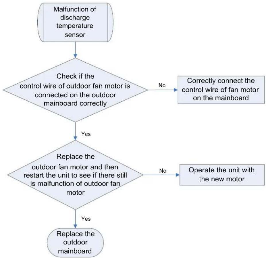
flowchart
graph TD
    A["Malfunction of discharge temperature sensor"] --> B{Check if the control wire of outdoor fan motor is connected on the outdoor mainboard correctly}
    B -->|No| C["Correctly connect the control wire of fan motor on the mainboard"]
    B -->|Yes| D{Replace the outdoor fan motor and then restart the unit to see if there still is malfunction of outdoor fan motor}
    D -->|No| E["Operate the unit with the new motor"]
    D -->|Yes| F["Replace the outdoor mainboard"]
3.4.12 "H7" Driver Out-of-Step Protection
Error display: ODU mainboard LED displayer
Error judgment condition and method:
During operation, it can't detect the rotor position and stops output. Or the actual running speed differs too much from the set running speed. In each case, compressor runs out of step and system stops for protection.
Possible reason:
■Compressor 3-phase wire connection is lack of phase or phased-reversed.
■Compressor phase wire connection is bad.
■System is blocked, short of refrigerant or compressor oil.
■Drive board IPM module is damaged.
■Drive board compressor current sampling circuit element is damaged or drive chip current sampling AD terminal is abnormal.
■Compressor is damaged.
Troubleshooting:
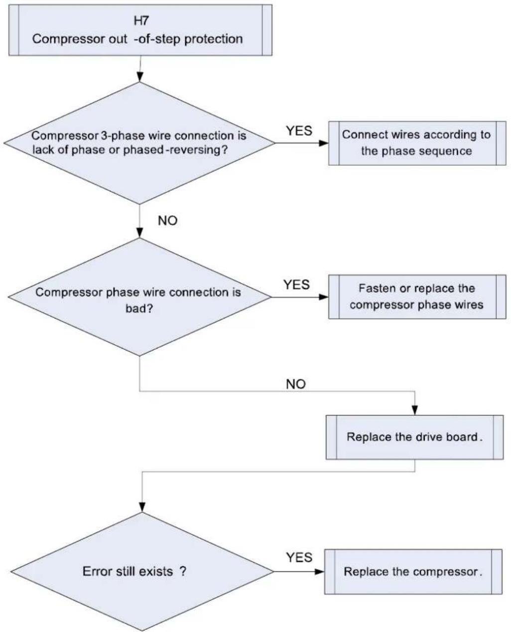
flowchart
graph TD
    A["H7\nCompressor out -of-step protection"] --> B{Compressor 3-phase wire connection is lack of phase or phased-reversing?}
    B -->|YES| C["Connect wires according to the phase sequence"]
    B -->|NO| D{Compressor phase wire connection is bad?}
    D -->|YES| E["Fasten or replace the compressor phase wires"]
    D -->|NO| F["Replace the drive board."]
    F --> G{Error still exists ?}
    G -->|YES| H["Replace the compressor."]
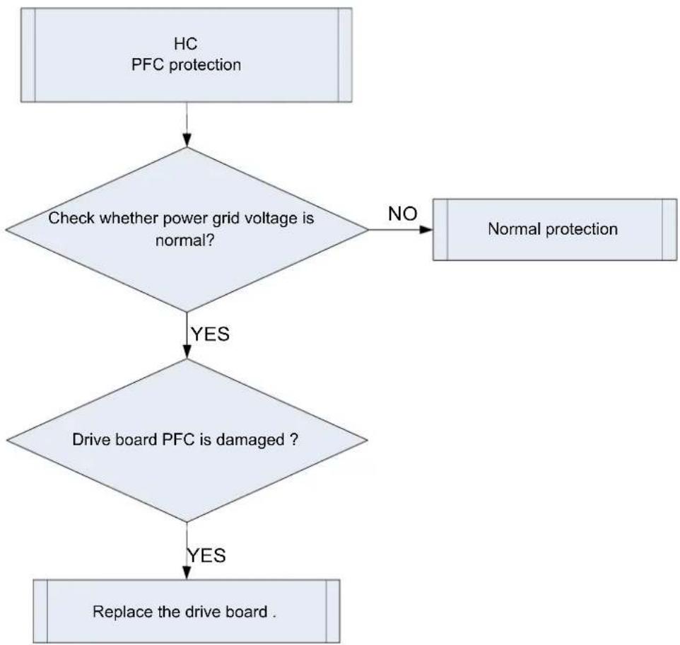
3.4.13 "HC" PFC Protection
Error display: ODU mainboard LED displayer
Error judgment condition and method:
After power is connected, and drive chip received PFC lead F0 that is of low level, than it is PFC module malfunction. System will shut down for protection.
Possible reason:
■Power grid voltage is abnormal.
■Drive board PFC module is damaged.
■Drive board PFC module's 15V power supply is lower than 13.5V.
■Drive board PWM signal for PFC and the corresponding element are abnormal.
■Drive board PFC current sampling circuit element is damaged or drive chip current sampling AD terminal is abnormal.
Troubleshooting:
flowchart
graph TD
    A["HC PFC protection"] --> B{Check whether power grid voltage is normal?}
    B -->|NO| C["Normal protection"]
    B -->|YES| D{Drive board PFC is damaged ?}
    D -->|YES| E["Replace the drive board ."]
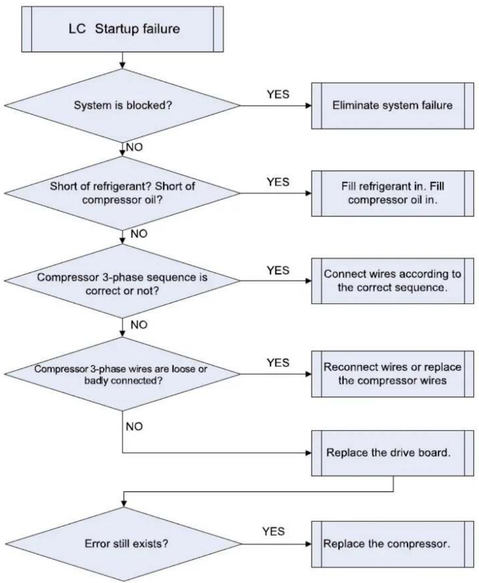
3.4.14 "Lc" Startup Failure
Error display: ODU mainboard LED displayer
Error judgment condition and method:
Check the error code on nixie tube of ODU main control board. If PJ is displayed, it indicates inverter compressor startup failure
Possible reason:
■Poor contact of compressor UVW wire;
■Compressor is broken;
■Compressor drive board is broken;
Troubleshooting:
flowchart
graph TD
    A["LC Startup failure"] --> B{System is blocked?}
    B -->|YES| C["Eliminate system failure"]
    B -->|NO| D{Short of refrigerant? Short of compressor oil?}
    D -->|YES| E["Fill refrigerant in. Fill compressor oil in."]
    D -->|NO| F{Compressor 3-phase sequence is correct or not?}
    F -->|YES| G["Connect wires according to the correct sequence."]
    F -->|NO| H{Compressor 3-phase wires are loose or badly connected?}
    H -->|YES| I["Reconnect wires or replace the compressor wires"]
    H -->|NO| J["Replace the drive board."]
    J --> K{Error still exists?}
    K -->|YES| L["Replace the compressor."]
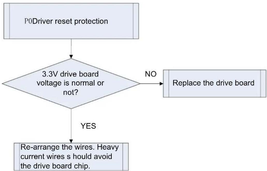
3.4.15 "P0" Driver Reset Protection
Error display: ODU mainboard LED displayer
Error judgment condition and method:
Drive board chip resets and starts initialization. After the drive board is energized for 5s, it detects that the chip resets again. In this case, it can be judged as drive chip reset protection.
Possible reason:
■3.3V drive chip supply voltage drop.
■TRST lead of JTAG programming is interrupted.
Troubleshooting:
flowchart
graph TD
    A["P0Driver reset protection"] --> B{3.3V drive board voltage is normal or not?}
    B -->|NO| C["Replace the drive board"]
    B -->|YES| D["Re-arrange the wires. Heavy current wires s hould avoid the drive board chip."]
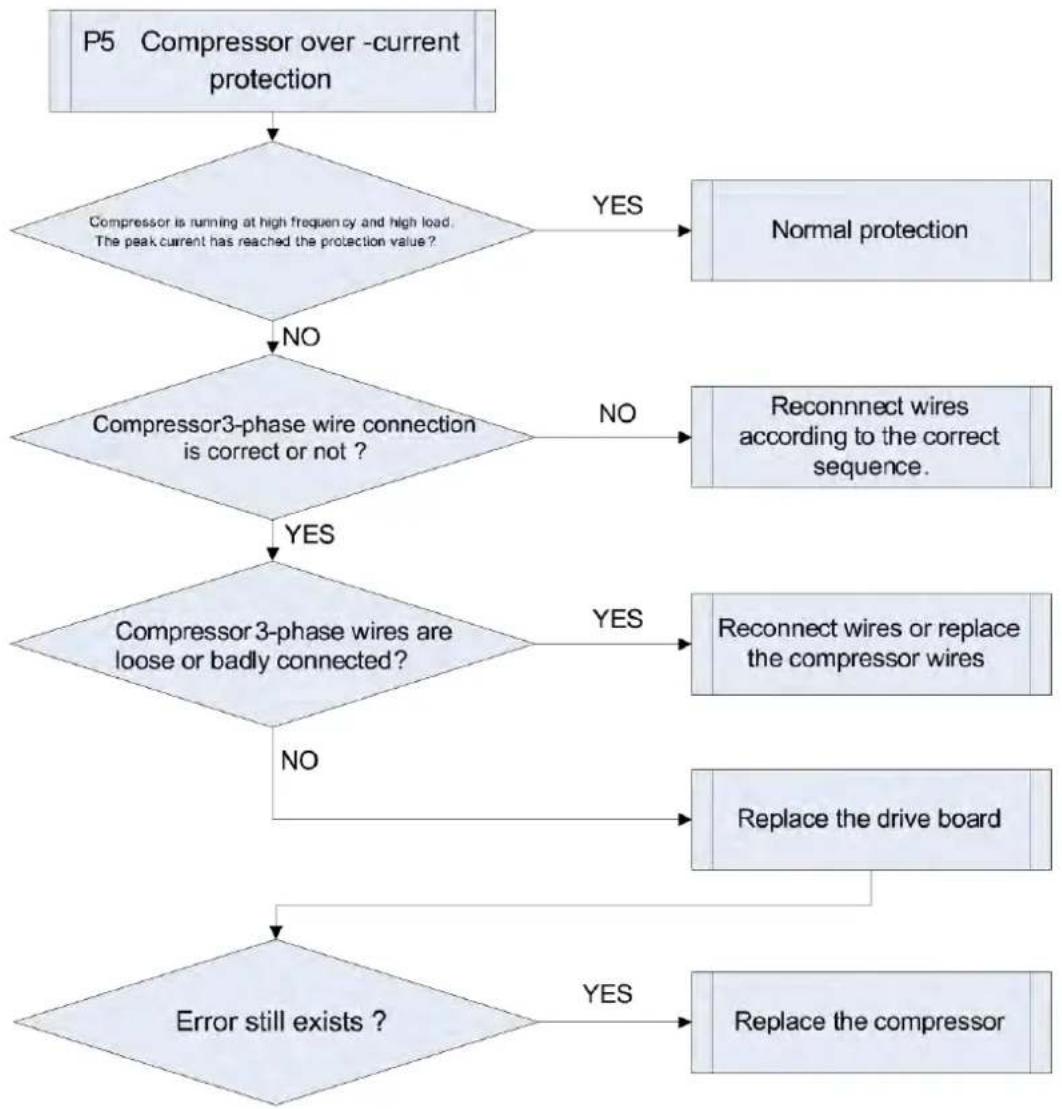
3.4.16 "P5" Over-Current Protection
Error display: ODU mainboard LED displayer
Error judgment condition and method:
If compressor's instant current value is higher than the set current protection value, then it can be judged that compressor over-current occurs and system will shut down for protection.
Possible reason:
■System load is too much and compressor current is too large.
■Compressor 3-phase wire connection is lack of phase or phase-reversed.
■Compressor phase wire is loose or has bad contact.
■Drive board current sampling circuit element is damaged or drive chip current sampling AD terminal is abnormal.
■Compressor is damaged.
Troubleshooting:
flowchart
graph TD
    A["P5 Compressor over -current protection"] --> B{Compressor is running at high frequency and high load. The peak current has reached the protection value?}
    B -->|YES| C["Normal protection"]
    B -->|NO| D{Compressor3-phase wire connection is correct or not?}
    D -->|NO| E["Reconnect wires according to the correct sequence."]
    D -->|YES| F{Compressor 3-phase wires are loose or badly connected?}
    F -->|YES| G["Reconnect wires or replace the compressor wires"]
    F -->|NO| H["Replace the drive board"]
    G --> I["Error still exists?"]
    H --> I
    I -->|YES| J["Replace the compressor"]
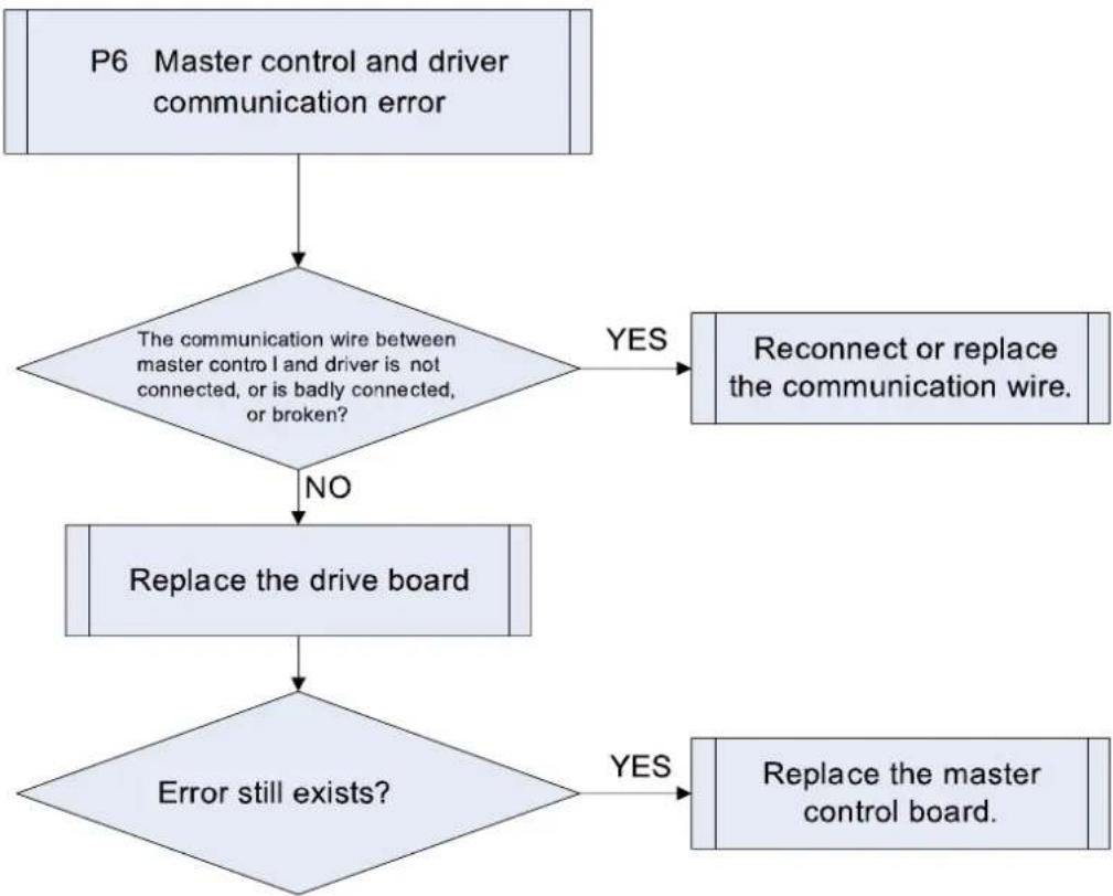
3.4.17 "P6" Master Control and Driver Communication Error
Error display: ODU mainboard LED displayer
Error judgment condition and method:
If there is no other malfunction and the communication between master control and driver is cut off for 30s, then it can be judged that the communication between master control and driver is faulted. System will shut down for protection.
Possible reason:
■Communication wire between master control and driver is not well connected, or has bad contact, or is broken.
■The switch power of drive board is abnormal, therefore, the 3.3V power voltage is abnormal.
■Communication circuit of the drive board or the master control board is abnormal.
Troubleshooting:
flowchart
graph TD
    A["P6 Master control and driver communication error"] --> B{The communication wire between master control and driver is not connected, or is badly connected, or broken?}
    B -->|YES| C["Reconnect or replace the communication wire."]
    B -->|NO| D["Replace the drive board"]
    D --> E{Error still exists?}
    E -->|YES| F["Replace the master control board."]
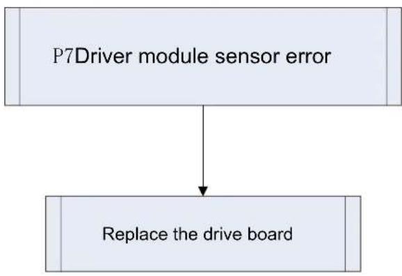
3.4.18 "P7" Driver Module Sensor Error
Error display: ODU mainboard LED displayer
Error judgment condition and method:
If IPM or PFC module temperature is lower than the set protection value, then it can be judged that driver module sensor error occurs and system will shut down for protection.
Possible reason:
■Module temperature sensor is short-circuited or broken-circuited.
■Drive board current sampling circuit element is damaged or drive chip current sampling AD terminal is abnormal.
Troubleshooting:
flowchart
graph TD
    A["P7Driver module sensor error"] --> B["Replace the drive board"]
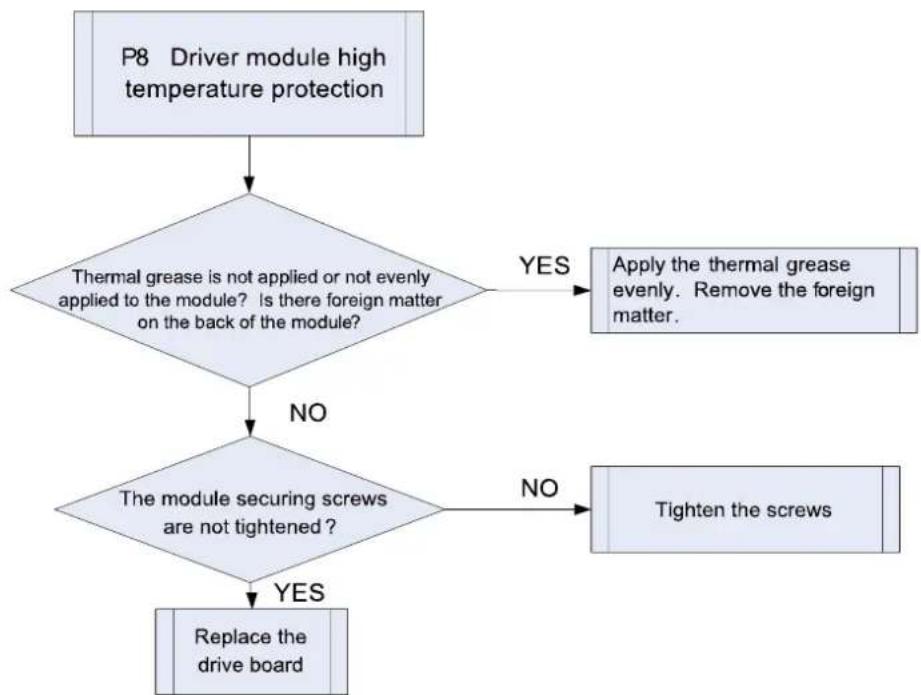
3.4.19 "P8" Driver Module High Temperature Protection
Error display: ODU mainboard LED displayer
Error judgment condition and method:
If IPM module temperature or PFC module temperature exceeds the set protection value, then it can be judged that driver module temperature is too high and system will shut down for protection.
Possible reason:
■Thermal grease is not applied or not evenly applied to the module, or there is other substance on the back of the module.
■The module securing screws are not tightened up.
■Drive board temperature sampling circuit element is damaged or drive chip temperature sampling AD terminal is abnormal.
Troubleshooting:
flowchart
graph TD
    A["P8 Driver module high temperature protection"] --> B{Thermal grease is not applied or not evenly applied to the module? Is there foreign matter on the back of the module?}
    B -->|YES| C["Apply the thermal grease evenly. Remove the foreign matter."]
    B -->|NO| D{The module securing screws are not tightened?}
    D -->|NO| E["Tighten the screws"]
    D -->|YES| F["Replace the drive board"]
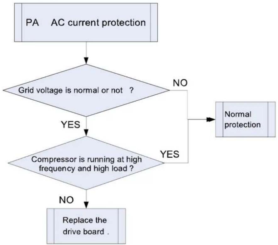
3.4.20 "PA" AC Current Protection
Error display: ODU mainboard LED displayer
Error judgment condition and method:
If input current value exceeds the set protection value, then it can be judged that AC current protection occurs and system will shut down for protection.
Possible reason:
■System is heavy-loaded and compressor current is too large.
■Grid voltage is abnormal.
■PFC module is damaged.
■Drive board PFC current sampling circuit element is damaged or drive chip PFC current sampling AD terminal is abnormal.
Troubleshooting:
flowchart
graph TD
    A["PA AC current protection"] --> B{Grid voltage is normal or not ?}
    B -->|YES| C["Compressor is running at high frequency and high load ?"]
    B -->|NO| D["Normal protection"]
    C -->|YES| D
    C -->|NO| E["Replace the drive board ."]
3.4.21 "Pc" Driver Current Error
Error display: ODU mainboard LED displayer
Error judgment condition and method:
After power charging, if offset voltage average is detected to exceed 12.5% of 1.65V in 1s, then it can be judged that current detection (or current sensor) circuit is faulted. System will shut down for protection.
Possible reason:
■Current detection (or current sensor) sampling circuit element is abnormal.
■Drive chip compressor current sampling AD terminal is badly welded or short-circuited.
Troubleshooting:
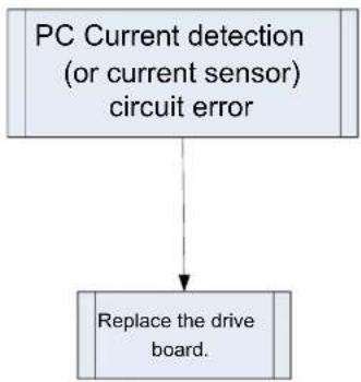
flowchart
graph TD
    A["PC Current detection (or current sensor) circuit error"] --> B["Replace the drive board."]
3.4.22 "PL" Bus Low-Voltage Protection
Error display: ODU mainboard LED displayer
Error judgment condition and method:
When compressor is running and there is no other malfunction, if busbar voltage is lower than the set value for low voltage protection, then it can be judged that bus low-voltage protection occurs. System will shut down for protection.
Possible reason:
■Voltage of power grid is abnormal.
■Drive board busbar voltage sampling circuit element is damaged or drive board busbar voltage sampling AD terminal is abnormal.
Troubleshooting:
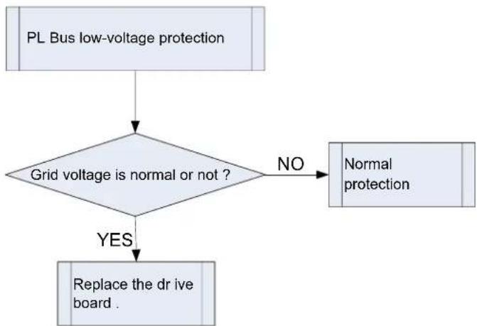
flowchart
graph TD
    A["PL Bus low-voltage protection"] --> B{Grid voltage is normal or not ?}
    B -->|NO| C["Normal protection"]
    B -->|YES| D["Replace the drive board ."]
3.4.23 "PH" Bus High-Voltage Protection
Error display: ODU mainboard LED displayer
Error judgment condition and method:
If there is no other malfunction and the busbar voltage is higher than the set value for high voltage protection, then it can be judged that bus high-voltage protection occurs. System will shut down for protection.
Possible reason:
■Voltage of power grid is abnormal.
■Drive board busbar voltage sampling circuit element is damaged or drive board busbar voltage sampling AD terminal is abnormal.
Troubleshooting:
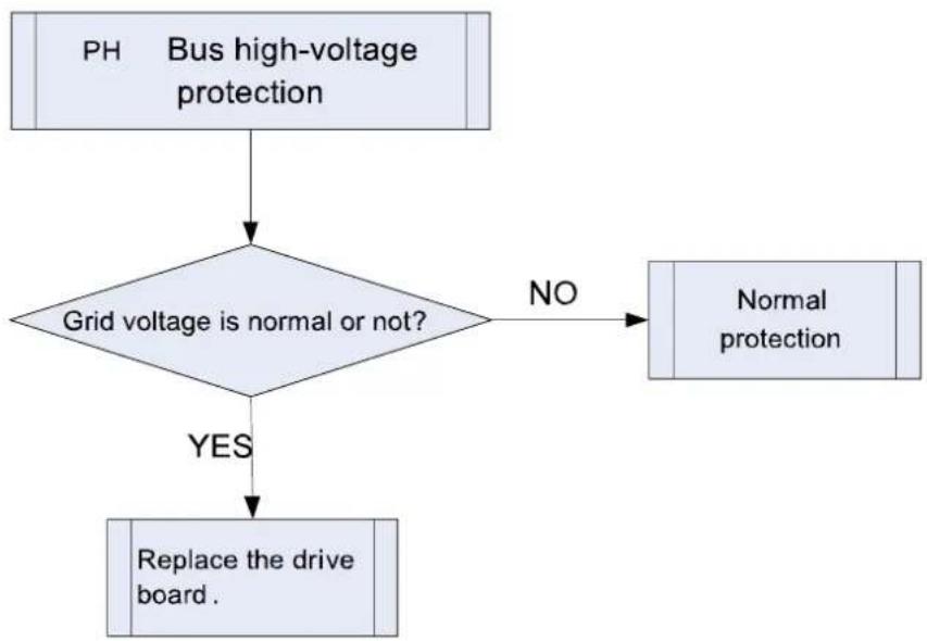
flowchart
graph TD
    A["PH Bus high-voltage protection"] --> B{Grid voltage is normal or not?}
    B -->|NO| C["Normal protection"]
    B -->|YES| D["Replace the drive board."]
3.4.24 "PU" Charge Loop Error
Error display: ODU mainboard LED displayer
Error judgment condition and method:
When the charge loop starts to get charged and the busbar voltage cannot reach the set value in a certain period of time, then it can be judged that charge loop error exists. System will shut down for protection.
Possible reason:
■Voltage of power grid is abnormal. Voltage is too low.
■Drive board charge loop element is abnormal.
■Drive board busbar voltage sampling circuit element is damaged or drive chip busbar voltage sampling AD terminal is abnormal.
Troubleshooting:
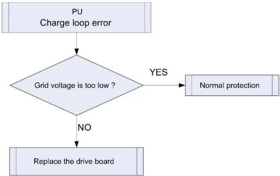
flowchart
graph TD
    A["PU\nCharge loop error"] --> B{Grid voltage is too low ?}
    B -->|YES| C["Normal protection"]
    B -->|NO| D["Replace the drive board"]
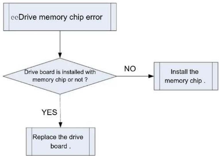
3.4.25 "ee" Drive Memory Chip Error
Error display: ODU mainboard LED displayer
Error judgment condition and method:
If power is connected but the drive board with memory chip cannot detect the memory chip or read the memory chip data correctly, then it can be judged that drive memory chip error exists.
Possible reason:
■The drive board that needs memory chip is not installed with the memory chip.
■The lead or connector of memory chip is badly welded or short-circuited.
Troubleshooting:
flowchart
graph TD
    A["ccDrive memory chip error"] --> B{Drive board is installed with memory chip or not ?}
    B -->|NO| C["Install the memory chip ."]
    B -->|YES| D["Replace the drive board ."]
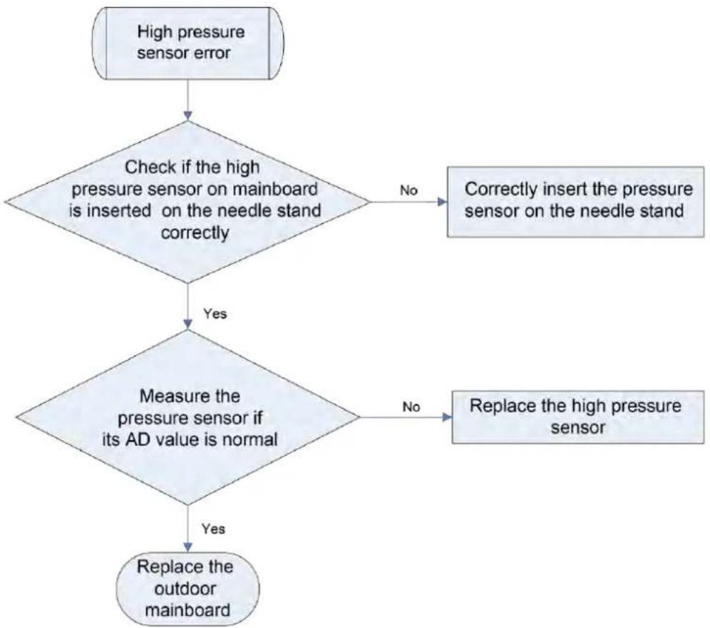
3.4.26 "e1" High Pressure Sensor Error
Error display: ODU mainboard LED displayer
Sample the AD value of pressure sensor through pressure sensor detecting circuit and judge the range of AD value, If the sampling AD value exceeds upper limit and lower limit in 30 seconds continuously, report the error.
■Poor contact between pressure sensor and terminal in mainboard interface
■Pressure sensor is abnormal
■Detecting circuit is abnormal
Troubleshooting:
flowchart
graph TD
    A["High pressure sensor error"] --> B{Check if the high pressure sensor on mainboard is inserted on the needle stand correctly}
    B -->|No| C["Correctly insert the pressure sensor on the needle stand"]
    B -->|Yes| D{Measure the pressure sensor if its AD value is normal}
    D -->|No| E["Replace the high pressure sensor"]
    D -->|Yes| F["Replace the outdoor mainboard"]
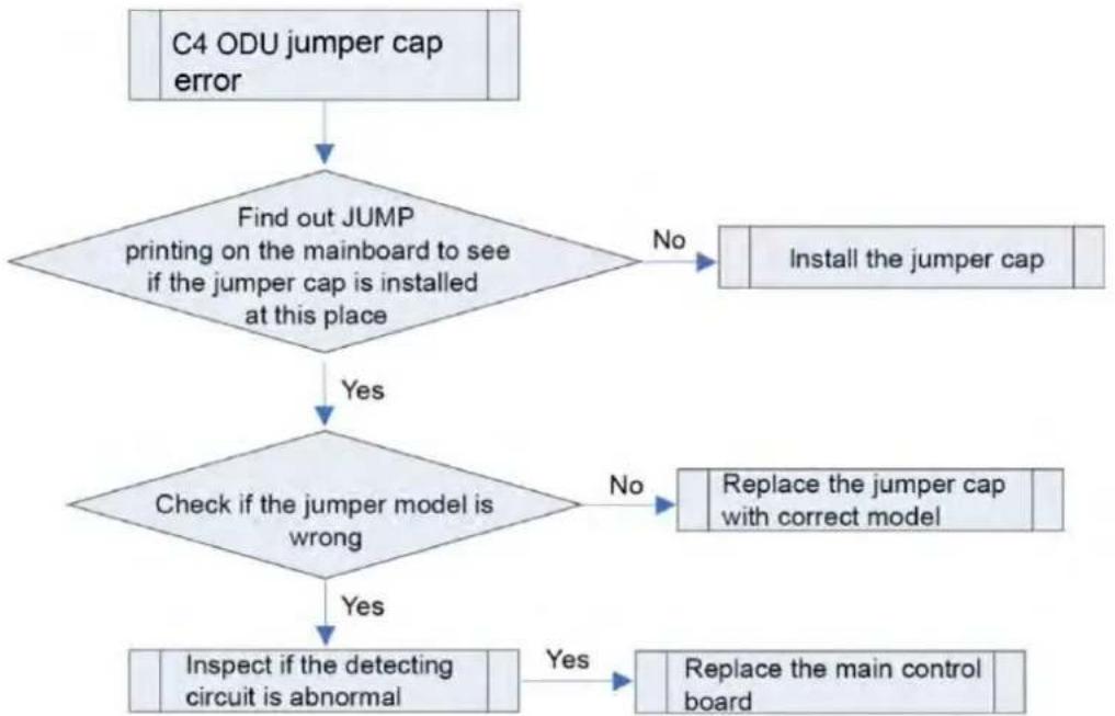
3.4.27 "C4" ODU Jumper Cap Error
Error display: ODU mainboard LED displayer
Error judgment condition and method:
If jumper cap model doesn't match with mainboard, report the error
Possible reason:
■Jumper cap is not installed
■Jumper cap model is wrong
■Detecting circuit is abnormal
Troubleshooting:
flowchart
graph TD
    A["C4 ODU jumper cap error"] --> B{Find out JUMP printing on the mainboard to see if the jumper cap is installed at this place}
    B -->|No| C["Install the jumper cap"]
    B -->|Yes| D{Check if the jumper model is wrong}
    D -->|No| E["Replace the jumper cap with correct model"]
    D -->|Yes| F["Inspect if the detecting circuit is abnormal"]
    E --> G["Replace the main control board"]
    F --> H["Yes"]
3.5 Failures Not Caused by Errors
(1) If your air conditioner fails to function normally, please first check the following items before maintenance:
| Problem | Cause | Corrective measure |
| The air conditioner can't run. | If you turn off the unit and then immediately turn it on, in order to protect the compressor and avoid system overload, compressor will delay running for 3min. | Please wait for a while. |
| Wire connection is wrong. | Connect wires according to the wiring diagram. | |
| Fuse or circuit breaker is broken. | Replace the fuse or switch on the circuit breaker. | |
| Power failure. | Restart after power is resumed. | |
| Power plug is loose. | Re-insert the power plug. | |
| Thermostat has low battery. | Replace the batteries. | |
| Bad cooling or heating effect. | Air inlet and outlet of the units have been blocked. | Clear the obstacles and keep the room for the units well ventilated. |
| Improper temperature setting | Reset a proper temperature. | |
| Fan speed is too low. | Reset a proper fan speed. | |
| Air flow direction is not right. | Change the direction of air louvers. | |
| Doors or windows are open. | Close them. | |
| Exposed under direct sunshine. | Put on curtains or louvers in front of the windows. | |
| Too many heat sources in the room. | Remove unnecessary heat sources. | |
| Filter is blocked or dirty. | Send for a professional to clean the filter. | |
| Air inlets or outlets of the units are blocked. | Clear away obstacles that are blocking the air inlets and outlets of the units. |
(2) The following situations are not operation failures.
| Problem | Time of occurrence | Cause |
| Mist comes from the air conditioner. | During operation. | If the unit is running under high humidity, the wet air in the room will be quickly cooled down. |
| The air conditioner generates some noise. | System switches to heating mode after defrosting. | Defrosting process will generate some water, which will turn to water vapor. |
| The air conditioner is buzzing at the beginning of operation. | Thermostat will be buzzing when it starts working. The noise will become weak 1min later. | |
| Dust comes from the air conditioner. | When the unit is turned on, it purrs. | When the system is just started, the refrigerant is not stable. About 30s later, the purr of the unit becomes low. |
| About 20s after the unit first enables the heating mode or there is refrigerant brushing sound when defrosting under heating. | It's the sound of 4-way valve switching direction. The sound will disappear after the valve changes its direction. | |
| There is hissing sound when the unit is started or stopped and a slight hissing sound during and after operation. | It's the sound of gaseous refrigerant that stops flowing and the sound of drainage system. | |
| There is a sound of crunching during and after operation. | Because of temperature change, front panel and other components may be swelled up and cause abrasion sound. | |
| There is a hissing sound when the unit is turned on or suddenly stopped during operation or after defrosting. | Because refrigerant suddenly stops flowing or changes the flow direction. | |
| The unit starts operation after being unused for a long time. | Dust inside the units come out together with the air. | |
| The air conditioner generates some smell. | During operation. | The room smell or the smell of cigarette comes out through the units. |

NOTICE:
Check the above items and adopt the corresponding corrective measures. If the air conditioner continues to function poorly, please stop the air conditioner immediately and contact MrCool's technical support center.
4 Maintenance
4.1 System Diagram
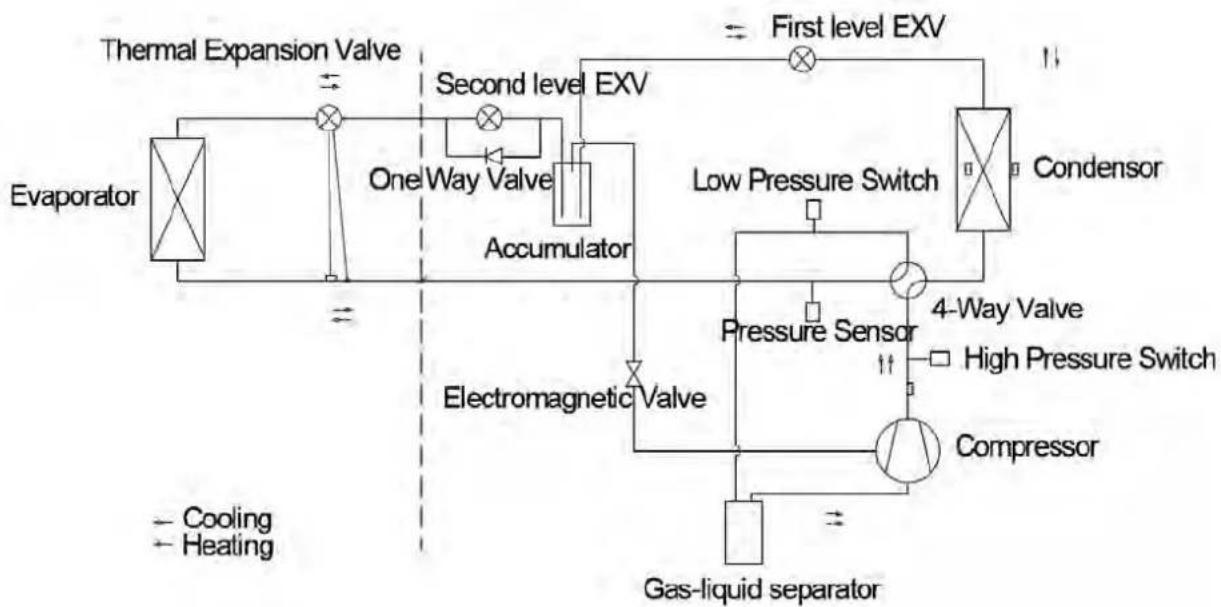
flowchart
graph TD
    A["Evaporator"] --> B["Thermal Expansion Valve"]
    B --> C["Second level EXV"]
    C --> D["One Way Valve"]
    D --> E["Accumulator"]
    E --> F["Electromagnetic Valve"]
    F --> G["4-Way Valve"]
    G --> H["High Pressure Switch"]
    H --> I["Compressor"]
    I --> J["Gas-liquid separator"]
    K["Low Pressure Switch"] --> L["Condensor"]
    M["Cooling"] --> N["Heating"]
    O["First level EXV"] --> P["Exterior"]
    Q["Electric Magnetic Valve"] --> R["Pressure Sensor"]
4.2 Connection Pipe Vacuum Pumping
 NOTICE NOTICE | |
| 1 | Make sure the outlet of vacuum pump is away from fire source and is well-ventilated. |
| 2 | Before vacuum pumping, make sure the unit cut-off valves are closed. |
| 3 | When vacuum pumping, both the liquid pipe and the gas pipe must be pumped. |
(1) Remove the caps of the liquid valve, gas valve and also the service port.
(2) meanwhile the gas and liquid valves should be kept closed in case of refrigerant leak.
(3) Connect the hose used for evacuation to the vacuum pump.
(4) Open the switch at the lower pressure side of the manifold valve assembly and start the vacuum pump.
Meanwhile, the switch at the high pressure side of the manifold valve assembly should be kept closed, otherwise evacuation would fail.
(5) The evacuation duration depends on the unit's capacity, generally.
| Model | Time(min) |
| MDUO18024036 | 35 |
| MDUO18048060 | 40 |
And verify if the pressure gauge at the low pressure side of the manifold valve assembly reads -0.1Mpa (-750mmHg), if not, it indicates there is leak somewhere. Then, close the switch fully and then stop the vacuum pump.
(6) Wait for 10min to see if the system pressure can remain unchanged. If the pressure increase, there may be leakage.
(7) Slightly open the liquid valve and let some refrigerant go to the connection pipe to balance the pressure inside and outside of the connection pipe, so that air will not come into the connection pipe when removing the hose. Notice that the gas and liquid valve can be opened fully only after the manifold valve assembly is removed.
(8) Place back the caps of the liquid valve, gas valve and also the service port.
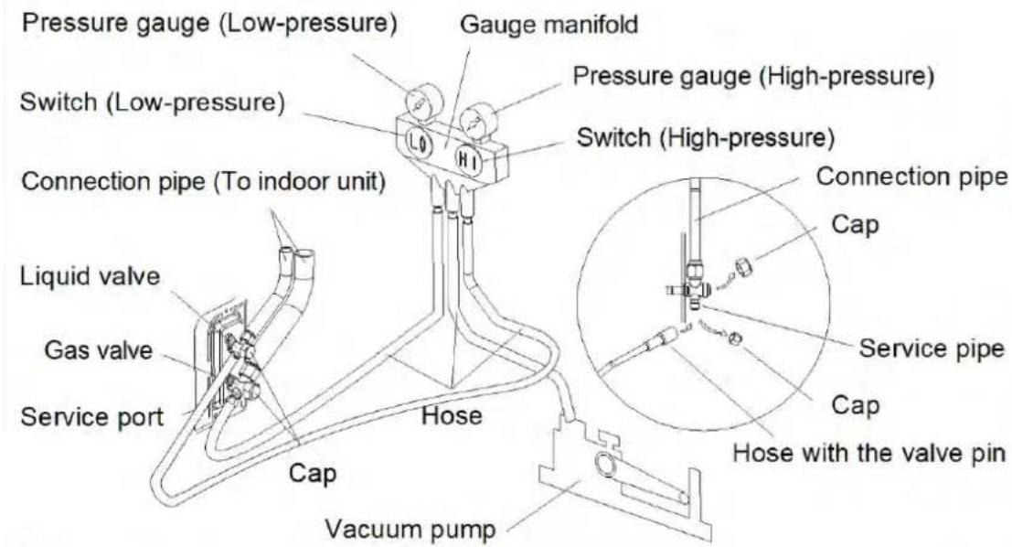

NOTICE:
For large-size units, there are maintenance ports for liquid valve and gas valve. During evacuation, you may connect the two hoses of the branch valve assembly to the maintenance ports to speed up the evacuation.
Refrigerant should be reclaimed into the appropriate storage tank. System should use oxygen-free nitrogen purging to ensure safety. This process may need to repeat several times. Do not use compressed air or oxygen in this process.
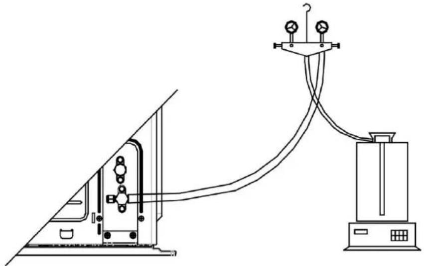
4.3 Refrigerant Charging
Pre-charging
Step 1: Connect the high pressure gauge line to the valve of liquid pipe and connect the low pressure gauge line to the valve of gas pipe. Connect the middle gauge line to the vacuum pump. Power on the vacuum pump and perform vacuum drying.
Step 2: After vacuum drying, close the high and low pressure gauge valves. Then remove the middle gauge line from the connector of vacuum pump. Then connect to the refrigerant tank.
Step 3: Loosen the middle gauge line from the connector of pressure gauge to a proper extent and slightly open the valve of refrigerant tank. Evacuate the middle gauge line. Then tighten up the connector again and completely open the valve of refrigerant tank at the same time.
Step 4: Keep the refrigerant tank erect and put it on an electronic scale. Record the current weight as m1.
natural_image
Technical line drawing of a mechanical testing setup with a pump, pressure gauge, and control unit (no text or labels)Step 5: Open the high pressure gauge valve (Keep the low pressure gauge valve closed). Then charge refrigerant into the system. Meanwhile, record the weight of refrigerant tank as m2.
Step 6: m1-m2=m. If m equals to the required charging quantity M, close the valve of refrigerant tank at once. Then move to step 8.
Step 7: If you can't continue to charge refrigerant into the system and the quantity of charged refrigerant is less than the required charging quantity, then record the current quantity of charged refrigerant:
$$ m = m 1 - m 2 $$
$$ m ^ {\prime} = M - m $$
The remaining charging quantity is: m`=M-m
Step 8: After charging, remove the pressure gauge.
Refrigerant charging when unit is turned on:
Step 1: Close the valve of refrigerant tank. First remove the pressure gauge lines and connect the outdoor unit to the indoor unit. Then reconnect the pressure gauge lines. Connect the low pressure gauge line to the other joint of gas valve and connect the high pressure gauge line to the liquid valve. Connect the middle gauge line to the vacuum pump. Power on the vacuum pump and perform vacuum drying.
Step 2: After vacuum drying, close the high and low pressure gauge valves. Then remove the middle gauge line from the connector of vacuum pump. Then connect to the refrigerant tank.
Step 3: Loosen the middle gauge line from the connector of pressure gauge to a proper extent and slightly open the valve of refrigerant tank. Evacuate the middle gauge line. Then tighten up the connector again and completely open the valve of refrigerant tank at the same time.
Step 4: Turn on the air conditioner and let it run for a while.
Step 5: Open the low pressure gauge valve (Keep the high pressure gauge valve closed). Then charge in the remaining charging quantity m'.
Step 6: After all required refrigerant is charged in, close the valve of refrigerant tank.
Step 7: Remove the pressure gauge to finish the refrigerant charging work.
Procedure of refrigerant charging
Following is the supplementary requirement for refrigerant charging on the basis of normal procedure:
1) Make sure that when charging refrigerant into the system, no other types of refrigerant will be mixed. The pipeline for refrigerant charging should be as short as possible to reduce the amount of refrigerant left in it.
2) The refrigerant tank should stand erect.
3) Make sure the refrigerating system is already grounded before refrigerant charging.
4) When charging is completed (or not yet completed), stick a label on the system.
5) Before re-charging refrigerant into the system, use oxygen-free nitrogen to perform pressure test. When charging is completed, perform leak test before trial running. Before leaving the workplace, perform a leak test again.
4.4 Maintenance of Major Components
4.4.1 Replacement of thermostat
Please refer to the instruction manual of thermostat XE70-00/E1.
4.4.2 How to replace the compressor
4.4.2.1 Diagnosis of compressor failure
A. On condition that the unit can be started up
Step 1:
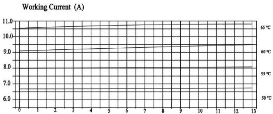
If the unit can be started up, then start it up to check the current of the faulted compressor. Use a pressure gauge to measure the pressure of the big and small valves. Connect with a computer to monitor the data. Refer to the following table based on the recommended working current. The electric current of an inverter compressor will be different under different rotation speed or different working conditions. If the compressor is working at 60Hz, the working current corresponding to different condensing temperature and evaporating temperature is shown below:
Inverter compressor QXFT-F310zN450
line
| Working Current (A) | 50 °C | 55 °C | 60 °C | 65 °C | | ------------------- | ----- | ----- | ----- | ----- | | 0 | 6.5 | 9.0 | 10.5 | 11.0 | | 1 | 6.5 | 9.0 | 10.5 | 11.0 | | 2 | 6.5 | 9.0 | 10.5 | 11.0 | | 3 | 6.5 | 9.0 | 10.5 | 11.0 | | 4 | 6.5 | 9.0 | 10.5 | 11.0 | | 5 | 6.5 | 9.0 | 10.5 | 11.0 | | 6 | 6.5 | 9.0 | 10.5 | 11.0 | | 7 | 6.5 | 9.0 | 10.5 | 11.0 | | 8 | 6.5 | 9.0 | 10.5 | 11.0 | | 9 | 6.5 | 9.0 | 10.5 | 11.0 | | 10 | 6.5 | 9.0 | 10.5 | 11.0 | | 11 | 6.5 | 9.0 | 10.5 | 11.0 | | 12 | 6.5 | 9.0 | 10.5 | 11.0 | | 13 | 6.5 | 9.0 | 10.5 | 11.0 |Inverter compressor QXAU-F516zX440A
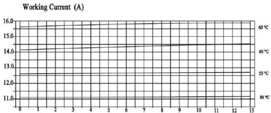
line
| Time | Working Current (A) | | ---- | ------------------- | | 0 | 11.0 | | 1 | 11.5 | | 2 | 12.0 | | 3 | 12.5 | | 4 | 13.0 | | 5 | 13.5 | | 6 | 14.0 | | 7 | 14.5 | | 8 | 15.0 | | 9 | 15.5 | | 10 | 16.0 | | 11 | 16.0 | | 12 | 16.0 | | 13 | 16.0 |Step 2:
Judge whether the operating noise of the compressor is normal, and whether there is a sharp noise or obvious scraping. If there is a normal compressor working nearby, compare their operating noise.
Step 3:
Examine whether the electronic expansion valve of the outdoor unit is active and whether the 4-way valve works or not. How to examine:
(1) Electronic expansion valve:
The electronic expansion valve will be reset every time when the unit is powered on or off. Touch the valve and you can feel the movement of the valve spool. In the last stage of the reset process, you will hear the click of the valve and feel its vibration.
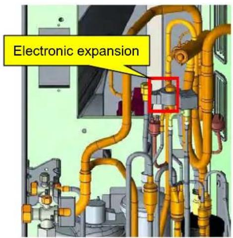
Touch the electronic expansion valve:
a. Touch the top of the electronic expansion valve and you can feel its move as it is reset upon startup.
b. Make sure the coil is fixed firmly.
(2) 4-way valve:
During normal operation, the 4 copper tubes that connect to the valve will have different temperature. When the 4-way valve is working, it will generate some noise and vibration.
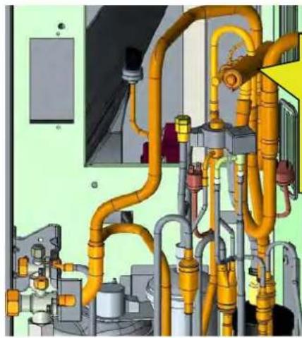
natural_image
Industrial piping system with yellow and gray pipes, no visible text or symbolsThis is the position of the 4-way valve. Do not touch it directly with your hands. There is hot refrigerant at the exhaust pipe, so be careful not to be scalded.
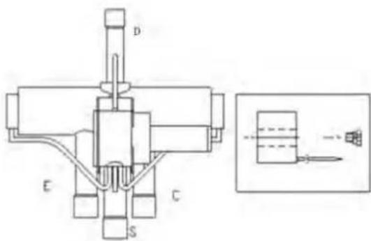
D- Connect to the exhaust side
Caution! High temperature!
Labels on the 4-way valve:
D-connect to the exhaust side; E-connect to the evaporator of indoor unit;
S-connect to the inhalation side of the liquid separator; C-connect to the condenser;
When the system is in cooling mode, C-the pipeline is with high pressure and high temperature; E, S-the pipeline is with low pressure and low temperature;
When the system is in heating mode, E-the pipeline is with high pressure and high temperature; C, S-the pipeline is with low pressure and low temperature;
Because D is connected to the exhaust side, it is with high pressure and high temperature regardless of the operating mode. When the unit is powered on, in defrosting or oil return mode, the 4-way valve will produce some noise. Do not touch the pipes directly with your hands and be cautious of the hot temperature.
Step 4:
Check the drive board of compressor, i.e. the IPM module.
Please refer to the IPM checking method in the section of troubleshooting.
Check the drive board of compressor, i.e. the IPM module.
Please refer to the IPM checking method in the section of troubleshooting.
B. On condition that the unit cannot be started up
Step 1:
Cut off the power supply and detach the cover of the wiring box of the compressor. Check the wiring of the compressor.
Step 2:
Check the resistance between the wiring terminals (U, V, W) of compressor.
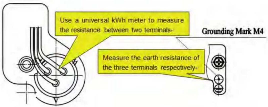
Refer to the following table for the resistance between any two terminals:
| Compressor model | UV Winding resistance | VW Winding resistance | WU Winding resistance |
| QXFT-F310zN450 | 0.79 ± 7% | 0.79 ± 7% | 0.79 ± 7% |
| QXAU-F516zX440A |
Measure the earth resistance of each wiring terminal. The resistance should be above 10 megohm. If not, we can judge that the compressor is faulted inside.
Step 3:
On condition that the unit cannot be started up, we also need to check the solenoid valve assembly of the system, including the electronic expansion valve. The checking method is the same as instructed above.
Step 4:
Check whether the IPM module is normal. Please refer to the IPM checking method in the section of troubleshooting.
4.4.2.2 Replacement of compressor
Step 1: Preparation
(1) Prepare the components for replacement
When carrying the old and new compressors, do not place the compressors horizontally or upside down. The angle of inclination should be within ± 30^ . Make sure the lubricant inside the compressors will not flow from the oil
balance mouth. The suction and exhaust openings of the compressors must be sealed. If a rubber seal is missing, user adhesive tape to seal the opening. This is to prevent the compressor oil from contacting the air.
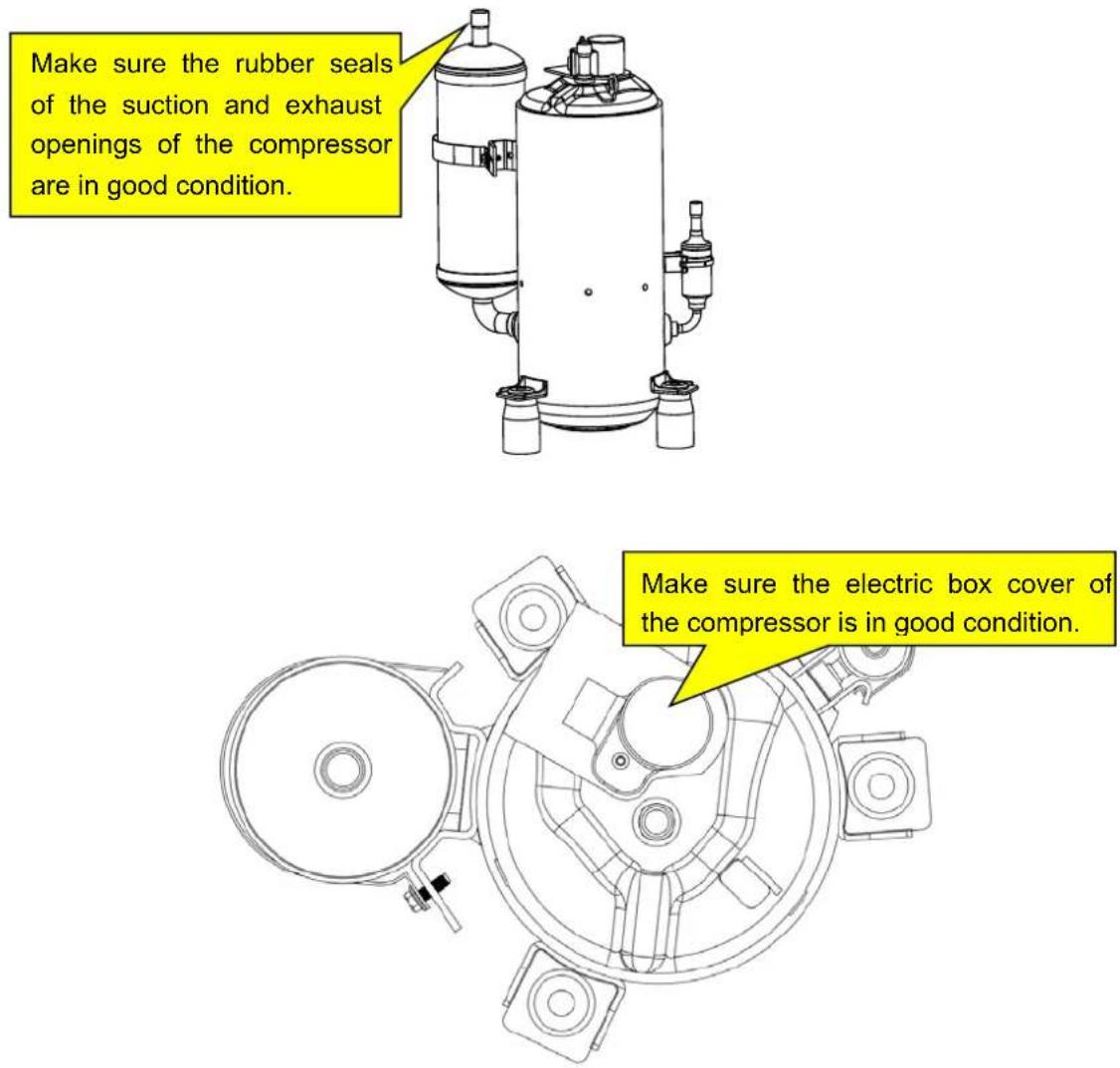

NOTICE: Before replacement, make sure the nameplates and models of the compressors are identical.

NOTICE: Make sure the lubricant is sealed inside the compressors.
(2) Prepare relevant tools
1) Prepare nitrogen. Please strictly follow the nitrogen welding standards during the welding process. Make sure there is sufficient nitrogen. The nitrogen pressure should be above 2.0MPa;
2) Prepare welding rods. Prepare some welding rods of common specifications and some special welding rods that contain more than 5 % silver. They are used to weld the compressor. The suction and exhaust openings of the compressor are all connected to copper-plated steel pipes, so we need to use special welding rods and solder;
3) Prepare applicable welding tools. Please evaluate how much oxygen and acetylene should be used according to the current welding condition. Try to avoid repeated welding.
4) Prepare a complete set of tools, including an internal hexagonal wrench, diagonal pliers, pincer pliers, nipper pliers, a universal meter, a pressure gauge, cross screwdriver, straight screwdriver, more than two wrenches, insulating tape and wire cables.
Step 2: Disconnect power
If the compressor needs to be replaced after judging as above, then switch off the outdoor unit and disconnect the power cable of the outdoor unit. Use insulating tape to wrap the power cable and put a notice board on the power switch to remind people to be cautious of electric shock.
Step 3: Neaten the electric components
When you detach the compressor wires, temperature sensors and electric heaters, mark them correspondingly for the convenience of reconnecting them.
Step 4: Discharge refrigerant
Discharge refrigerant from the system. Discharge simultaneously from the high pressure side and low pressure side. Do not discharge too fast (It should take more than 12h to completely discharge the refrigerant); otherwise, large quantity of lubricant will escape from the system together with the refrigerant.
Step 5: Detach the compressor
Check the condition of the damaged compressor, including its position and model.
If the information of the compressor is confirmed, check the oil quality.
(a) If the oil is clear and impurities-free, we consider that the oil of the system is not polluted. Meanwhile, if we confirm that the valves and pipes are also normal, then we can replace the compressor only. For the removal of compressor, please refer to the section: Removal of Major Components.
How to check oil quality:
(1) After the compressor is detached, put it on a solid ground and shake it at an angle of 30 45^ to ensure that the contaminant at the bottom of the compressor can be poured out.
(2) Place the compressor at a position above the ground level and then pour out the oil from the air outlet of the compressor. Collect the oil in a transparent container. The amount of oil should be over 150ml.
NOTE:
1) The axial direction of the compressor should not slant at an angle larger than 20^ to the horizontal direction.
2) Prevent the compressor from falling.
3) Put a transparent container (over 150ml in volume) under the exhaust pipe to collect the compressor oil, thus we can see the oil quality.
(3) Put the container of compressor lubricant in a bright location and see if there is impurity and discoloration. Sniff at the compressor lubricant. Normally, there is no pungent smell.
(b) If the oil is contaminated, replace the compressor and the gas-liquid separator.
NOTE: Confirm whether the compressor needs to be replaced. The pipe mouths of the faulted compressor must be sealed by adhesive tape as soon as the compressor is detached. Make sure the compressor is well preserved for the ease of future analysis.
Step 6: Check the components
If the oil is contaminated, check the components of the unit, including the gas-liquid separator.
Check the gas-liquid separator
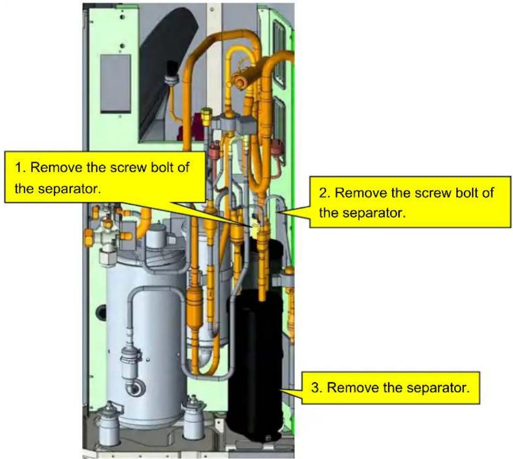
When the separator is detached, check whether there are impurities inside. Below is the checking method:
NOTE:
When pouring the liquid from the separator, make sure the discharge pipe is at the lower position. Slant at an angle not larger than 20^
Use a transparent container to collect the content inside the separator. Check its color, seal it well and return it to the factory for inspection.
NOTE:
If the compressor is damaged and needs to be replaced, the gas-liquid separator should also be replaced, whether or not there are impurities in the separator or other abnormal conditions.
Confirm which parts of the system should be replaced. Make sure the pipe mouths of the damaged parts or components are sealed by adhesive tape as soon as they are detached. Keep them in the original condition for future analysis.
Step 7: Clear the pipeline
After confirming which parts of the system should be replaced, check the pipeline of the system. Blow through the main pipeline with nitrogen. After clearing the pipeline, if the components are not replaced immediately, seal the pipeline with adhesive tape to prevent the system from being contaminated by water and impurities in the air.
Step 8: Replace the compressor
For the removal of compressor, please refer to the section: Removal of Major Components.
Step 9: Check/Replace the gas-liquid separator
NOTE:
If a compressor is damaged and needs to be replaced, its gas-liquid separator should also be replaced. This is to avoid the abnormal condition of the separator from affecting the safe and reliable operation of the system.
For the removal of gas-liquid separator, please refer to the section: Removal of Major Components.
Step 10: Check the system for leaks
(1) First of all, check each welding point. Check whether the welding points are smooth and whether there is any obvious welding hole or other abnormal condition.
(2) Next, fill high-pressure nitrogen into the system for leak detection. If it is only the outdoor unit that needs to be repaired and the indoor unit is confirmed normal, then it's OK to charge high-pressure nitrogen into the outdoor unit only. Fill in the nitrogen simultaneously from the high pressure side and low pressure side. We recommend charging the nitrogen from the big and small valves at the same time. The pressure of nitrogen should be above 20kgf. Then use soapy water to check for leaks. Check the welding points particularly.
(3) Finally, retain the pressure of the system. Fill high-pressure nitrogen into the system and maintain the pressure above 25kgf. Close the big and small valves and keep the pressure of indoor and outdoor units for more than 12h. If the pressure remains unchanged, then start vacuum pumping; otherwise, check the system for leaks again.
Temperature should be considered when judging the pressure change. If temperature changes by 1^ C
(33.8°F), pressure will change by 0.01MPa or so.
For example, if temperature is 30^(86^) when nitrogen of 2.5MPa is charged, and temperature changes to 25^ ( 77^ ) after 12h, we consider that the system is qualified if the pressure is found at 2.43MPa or above.
Step 11: Evacuate the system and charge refrigerant
Please refer to the section of maintenance: vacuum pumping and refrigerant charging.
Step 12: Connect electric components
Connect cables, compressor wires and the electric heating belt according to the signs marked before and the wiring diagram on the cover of the electric box.
4.4.3 How to replace the drive module of compressor
Step 1: First, make sure that power is cut off. Set the universal meter at the AC voltage and measure the voltage between L1, L2, L3, and N. If each time the voltage is 0V (Errors may occur to the universal meter, sometimes the voltage may not be 0V), proceed with the next step and put a sign on the power switch that reads "Under maintenance, don't switch on".
Step 2: Measure the voltage between DC bus P and N on the drive board of the compressor. Set the universal meter at the DC voltage and measure the voltage between P and N as shown below. If the voltage is below 36V, proceed with the next step. In case that a universal meter is not available, disconnect power for 20min and then continue with the next step.
Step 3: Remove all the wires on the drive board of the compressor.
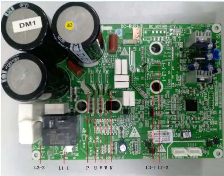
Step 4: Remove the screws on the drive board of the compressor. The screws are located in the white circles as shown above in the picture.
Step 5: Replace with a new compressor drive board. Before replacement, apply some silica gel on the IPM module.
Step 6: Install the new compressor drive board. Fix the screws and connect the wires correctly.
4.5 Removal of Major Components
4.5.1 Removal of ODU Major Components
| Picture | Name | Function | |
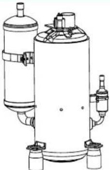 | Compressor | Through compression, the low pressure refrigerant occupies a less space. As its pressure and temperature both rise, it becomes high pressure and high temperature refrigerant. It is the power drive of the system. | |
 | 4-way valve | It is used to change directions, the flow of refrigerant in cooling/heating. | |
 | Motor | The power drive of the fan. It enables the fan to run so as to provide smooth currents of air for forced convection and heat exchange of condenser and evaporator. | |
 | Fan | It is used to provide smooth currents of air for forced convection and heat exchange of condenser and evaporator. | |
 | Gas liquid separator | Installed at the suction side of compressor, it can separate the liquefi refrigerant from the gaseous refrigerant to make sure that only gaseous refrigerant will be sucked into the compressor. If liquefied refrigerant gets inside the compressor, ineffective compressor or slugging phenomenon will occur. | |
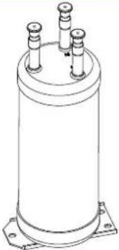 | Accumulator | Flash refrigerant from liquid to gas | |
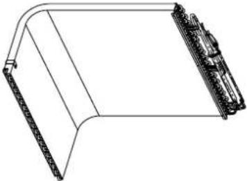 | Condenser | It is used to transfer partial heat of the hot flow to the cold flow so that the flow temperature can reach the specified index. It is an energy exchanging device. | |
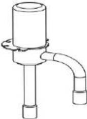 | Electronic expansion valve | It is used to lower the pressure and temperature of liquefied refrigerant and adjust the flow of refrigerant entering the evaporator. | |
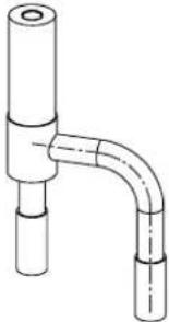 | Electromagnetic Valve | Electromagnetic valve controls increased enthalpy switch. | |
Model: MDUO18024036
| Removal of front panel | |||
| NOTE: Before removing the front panel, make sure power is cut off. | |||
| Step | Picture | Work instruction | |
| 1. Remove the upper cover plate. | 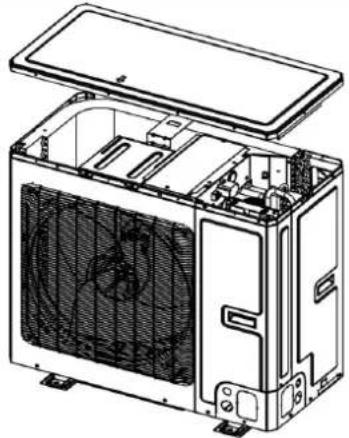 | Unscrew the screws of the upper cover plate with a screwdriver. | |
| 2. Remove the front side plate. | 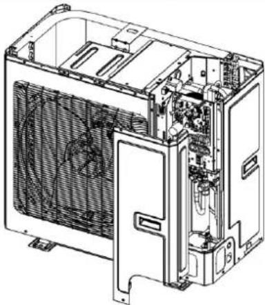 | Unscrew the screws of the upper and front side plate with a screwdriver. | |
| 3. Remove the front grill. | 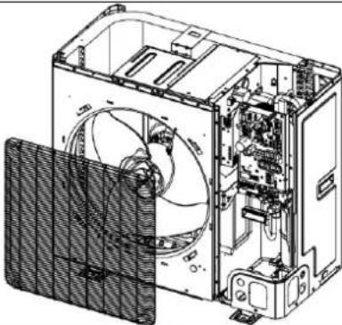 | Unscrew the screws of the front grill with a screwdriver. | |
| 4. Remove the front panel. | 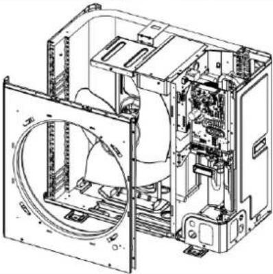 | Unscrew the screws that connect the front panel to the middle insulating board and screws around the front panel. | |
| 5. Remove the right side plate. |  | Unscrew the screws that connect the right side plate to the electric box and the screws around the right side plate. | |
| 6. Install the right side plate |  | Screw up the screws around the right side plate. Be careful to handle well the clasps at the bottom of the right side plate. | |
| 7. Install the front panel. |  | Install the front panel by mounting on 6 clasps on its both sides. Please note that there is one screw on the lower right side. | |
| 8. Install the grill. |  | Attach the grill back in place and tighten up the screws. | |
| 9. Install the front side plate. | 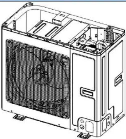 | ● Fix the clasps on both sides of the plate and tighten up the screws. | |
| 10. Install the upper cover plate. |  | ● Tighten up the screws around the upper cover plate. | |
Model: MDUO18024036
| Removal of compressor/gas liquid separator | ||
| NOTE: Before removing the compressor/gas liquid separator, make sure there is no refrigerant in the pipeline and power is cut off. | ||
| Step | Picture | Work instruction |
| 1. Remove wires. | 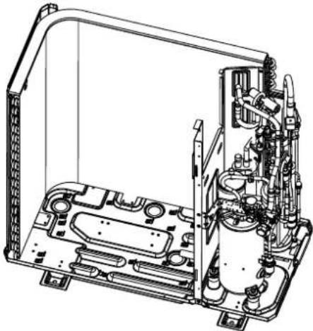 | Loosen the securing screws of the wires with a screwdriver.Remove the wires.NOTE: When removing the wires, mark the wire terminals corresponding to their color so as to avoid misconnection. |
Removal of compressor/gas liquid separator
| NOTE: Before removing the compressor/gas liquid separator, make sure there is no refrigerant in the pipeline and power is cut off. | ||
| Step | Picture | Work instruction |
| 2. Break off the pipes that connecting to the compressor/gas liquid separator. | 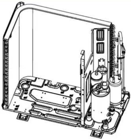 | Weld the pipes that are connected to the compressor/gas liquid separator.Then remove the pipes.NOTE: When welding the pipes, do not let the flame burn the other components. |
| 3. Loosen the compressor's base connectors / gas liquid separator's base nuts. | 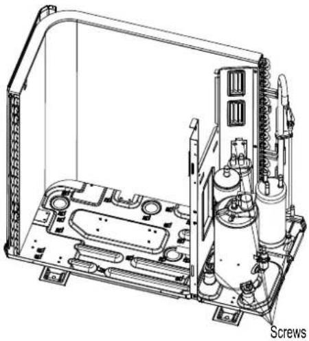 | Use a wrench to twist off the compressor/gas liquid separator's base nuts. |
| 4. Remove the compressor/gas liquid separator from the chassis. | 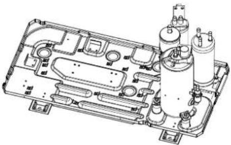 | Take away the compressor/gas liquid separator and replace with a new one.NOTE: When replacing the compressor/gas liquid separator, avoid touching the nearby pipeline and components. |
| Removal of compressor/gas liquid separator | ||
| NOTE: Before removing the compressor/gas liquid separator, make sure there is no refrigerant in the pipeline and power is cut off. | ||
| Step | Picture | Work instruction |
| 5. Install the new compressor/gas liquid separator onto the chassis. | 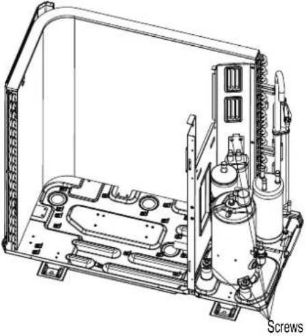 | After replacing the compressor/gas liquid separator, tighten up the base screw nuts. |
| 6. Connect the welding interfaces of compressor/gas liquid separator to the pipeline. | 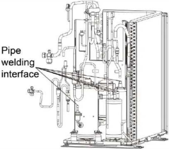 | Weld the connection pipes of compressor so as to connect them to the compressor.NOTE: When replacing the compressor, avoid touching the nearby pipeline and components. |
| 7. Connect the compressor wires. | 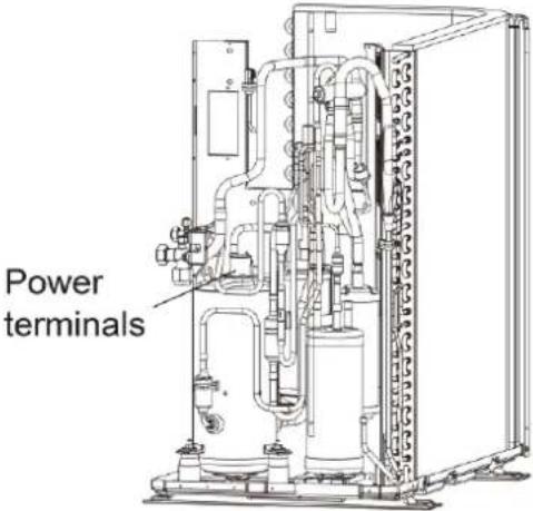 | Connect the compressor wires to the wire terminals on the top of compressor.NOTE: When connecting the wires, be sure to match the colors with the corresponding wire terminals. |
Model: MDUO18024036
| Removal of 4-way valve | ||
| NOTE: Before removing the 4-way valve, make sure refrigerant is fully discharged from the unit and power is cut off. | ||
| Step | Picture | Work instruction |
| 1. Take off the coil of the 4-way valve. | 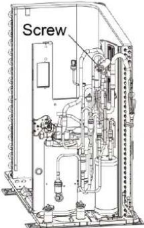 | Carefully unscrew the screws of electromagnetic coil with a screwdriver. |
| 2. Break off the connection pipes from the 4-way valve. | Four-wav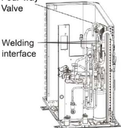 | Use a soldering gun to loosen the 4 joints on the 4-way valve and then remove the connection pipes.NOTE: When welding the pipes, the 4-way valve should be wrapped with wet cloth for cooling. Do not let the flame burn the other components. |
| 3. Replace the 4-way valve and connect it to the connection pipes. | Four-wav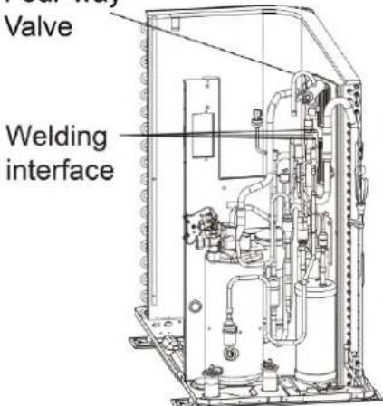 | Replace the 4-way valve and then use a soldering gun to weld the 4 joints of the 4-way valve.NOTE:When welding the pipes, the 4-way valve should be wrapped with wet cloth for cooling. Do not let the flame burn the other components. |
| 4. Install the coil of 4-way valve. | 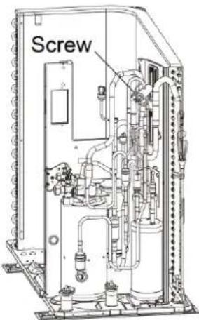 | ● Tighten the screws of the coil of 4-way valve with a screwdriver. |
Model: MDUO18024036
| Removal of fan and motor | ||
| Note: Before removing the fan, make sure power is cut off. | ||
| Step | Picture | Work instruction |
| 1. Remove the grill. | 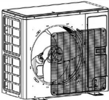 | Use a screwdriver to unscrew the two screws on the upper left and lower right corners. |
| 2. Remove the fan. | 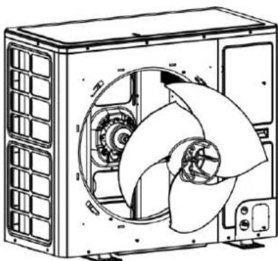 | Use a wrench to remove the specialized nut and gasket of the fan.NOTE: Please keep the nut and gasket safe after removing them from the fan. |
| 3. Remove motor. | 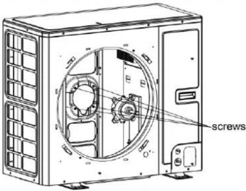 | Use a screwdriver to unscrew the bolt of motor.NOTE: Motor wire should be first removed from the electric box. |
| 4. Install the motor. | 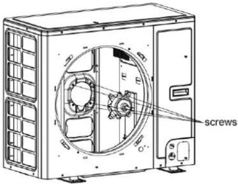 | Replace with a new motor.Then tighten up the screw bolt. |
| 5. Install the fan. | 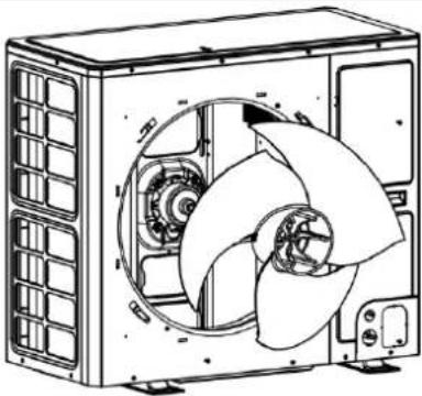 | Install the fan in place. Put on the gasket and use a wrench to secure the screw nut.NOTE: After installing the fan, turn the fan by hand to see if it can run normally. If not, please check for the reason. |
| 6. Install the grill. | 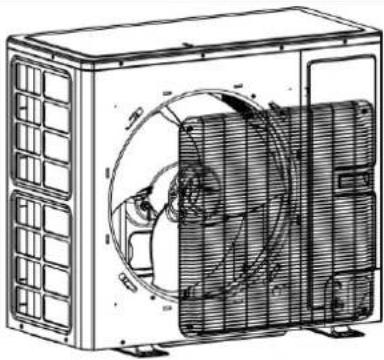 | After replacing the motor, use a screwdriver to tighten up the screw bolt that secures the motor.Arrange the wires according to the wiring diagram. |
Model: MDUO18024036
| Removal of condenser | ||
| NOTE:Before removing the condenser, make sure there is no refrigerant in the pipeline and power is cut off. | ||
| Step | Picture | Work instruction |
| 1. Remove the panels. | 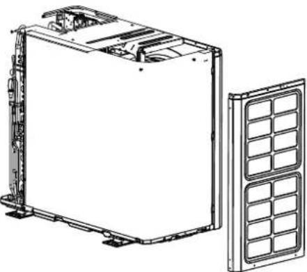 | Remove the upper, lower and front panels. |
| 2. Remove the electric box. | 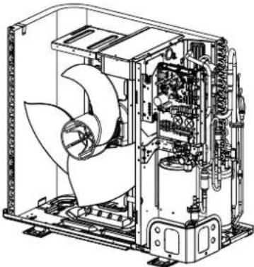 | Loosen the wire clamp at the bottom of the electric box.Unscrew the screws of electric box.The connection wires inside and outside the electric box should be removed. |
| 3. Remove motor support. | 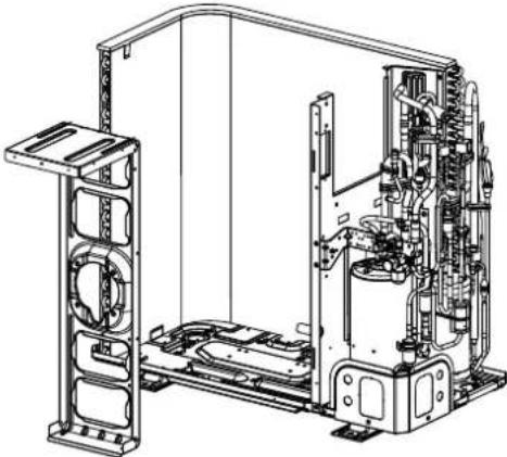 | When removing the motor support, be careful to protect the components. |
| 4. Remove the condenser. | 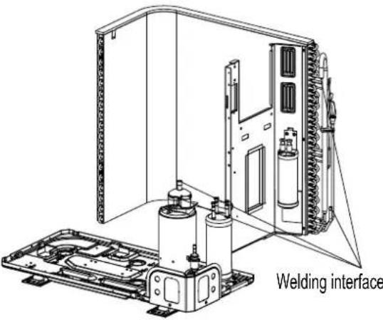 | Heat up the welding points of connection pipes through gas welding until the pipes break off.NOTE:When welding the pipes, do not let the flame burn the other components. The welding points of condenser are steel and copper welding points. Be sure to maintain the welding quality. |
| 5. Take out the condenser. | 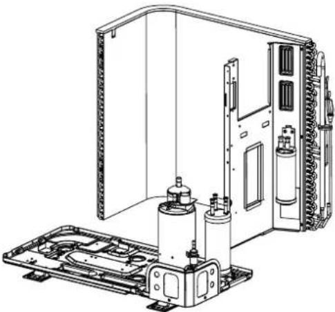 | Loosen the securing screws of condenser support. Take off the plate type heat exchanger and the support as a whole. |
| 6. Install the new condenser. |  | Secure the screws of condenser and support. Then fix them together on the chassis.Install the condenser by referring to the positions of entering and leaving pipes. Weld the connection pipes.Nitrogen welding: the pressure of nitrogen is 0.5±0.1kgf/ cm2 (relative pressure).NOTE:When welding the pipes, do not let the flame burn the other components. |
| 7. Secure the electric box and arrange the wires according to the requirement. | 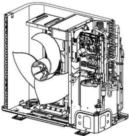 | ● Put the electric box in place and tighten up the screws of electric box.● Arrange and secure the wires as original. |
| 8. Check and open the upper and side panels. | 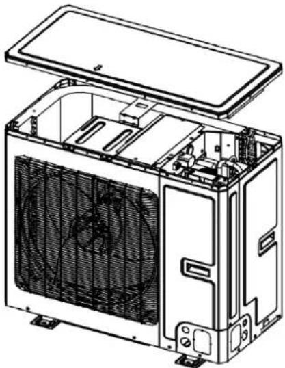 | ● Check whether each component and connection wire is well connected.● If everything is OK, place back the upper, left and right side panels. |
Model: MDUO18024036
| Removal of electronic expansion valve | ||
| NOTE:Before removing the electronic expansion valve, make sure there is no refrigerant in the pipeline and power is cut off. | ||
| Step | Picture | Work instruction |
| 1. Remove the electric box. | 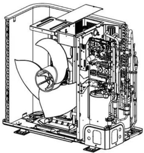 | Remove the upper, lower and front panels.Loosen the wire clamp at the bottom of the electric boxUnscrew the screws of electric box.The connection wires inside and outside the electric box should be removed.When removing the electric box, be careful to protect the components. |
| 2. Remove the fixed block. | 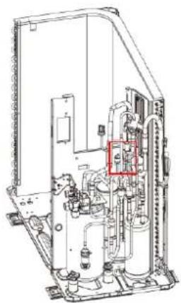 | Remove the fixed block between the electronic expansion valve and the pipe. |
| 3. Remove the electronic expansion valve. | 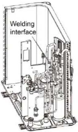 | Take off the coil of electronic expansion valve.Loosen the connection pipe of electronic expansion valve by welding. Then remove the connection pipe.NOTE:When welding the pipe, do not let the flame bunt the other components. |
| 4. Take out the electronic expansion valve. | 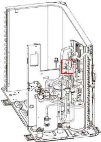 | Take out the electronic expansion valve. |
| 5. Install the new electronic expansion valve. | 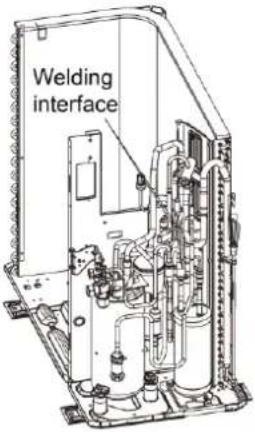 | Weld the connection pipe of electronic expansion valve.When welding the electronic expansion valve, the valve should be wrapped with wet cloth.Nitrogen welding: the pressure of nitrogen is 0.5 ± 0.1 kgf/ cm2 (relative pressure).NOTE:When welding the pipes, do not let the flame burn the other components.Install the coil of electronic expansion valve. |
Removal of electronic expansion valve
| NOTE:Before removing the electronic expansion valve, make sure there is no refrigerant in the pipeline and power is cut off. | |||
| Step | Picture | Work instruction | |
| 6. Secure the electric box and arrange the wires as required. | 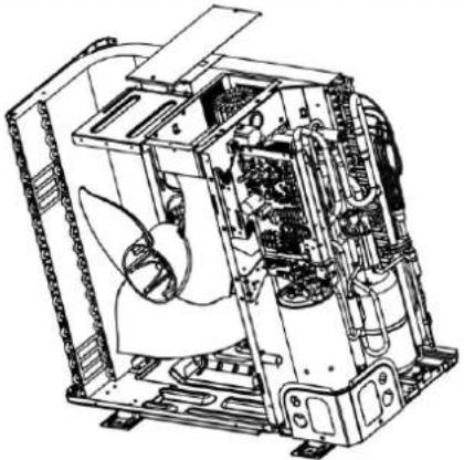 | ● Put the electric box back in place and tighten up the screws.● Arrange the wires as original. | |
| 7. Check and open the upper and front panels. | 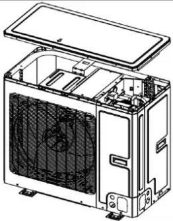 | ● Check whether each component and connection wire is well connected.● If everything is OK, install the upper, left and right panels. Tighten up the screws. | |
Model: MDUO18048060
| Removal of front panel | ||
| NOTE: Before removing the front panel, make sure power is cut off. | ||
| Step | Picture | Work instruction |
| 1. Remove the upper cover plate. | 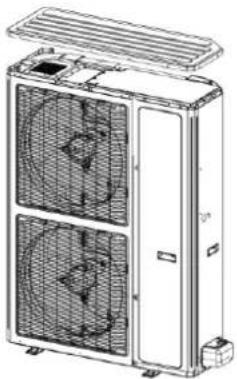 | ● Unscrew the screws of the upper cover plate with a screwdriver. |
| 2. Remove the front plate. | 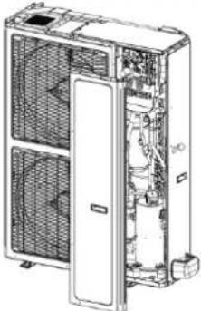 | Unscrew the screws of the front plate with a screwdriver. |
| 3. Remove the front grill. | 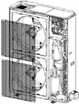 | Unscrew the screws of the front grill with a screwdriver. |
| 4. Remove the front panel. | 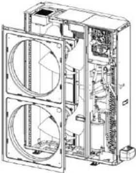 | Unscrew the screws that connect the front panel to the middle insulating board and screws around the front panel. |
| 5. Install the front panel. | 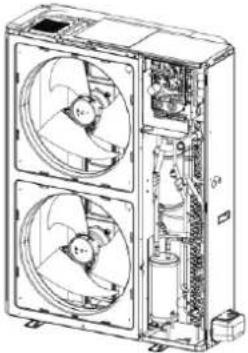 | Install the front panel by mounting on 6 clasps on its both sides. Please note that there is one screw on the lower right side. |
| 6. Install the grill. | 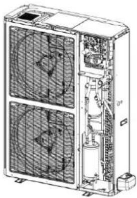 | Attach the grill back in place and tighten up the screws. |
| 7. Remove the valve cover | 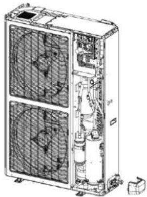 | Unscrew the screws of the valve cover with a screwdriver. |
| 8. Remove the right side plate. | 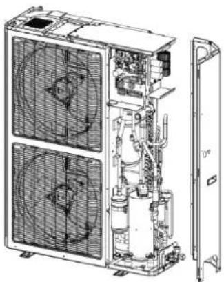 | Unscrew the screws that connect the right side plate to the electric box and the screws around the right side plate. |
| 9. Install the right side plate. | 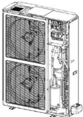 | Screw up the screws around the right side plate. Be careful to handle well the clasps at the bottom of the right side plate. |
| 10. Install the grill. | 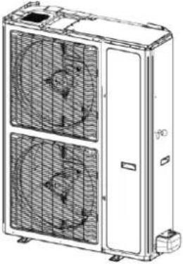 | Attach the grill back in place and tighten up the screws. |
| 11. Install the upper cover plate. | 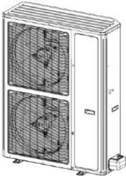 | Tighten up the screws around the upper cover plate. |
Model: MDUO18048060
| Disassembly of compressor | ||
| NOTE:Before removing the compressor, make sure there is no refrigerant in the pipeline and power is cut off. | ||
| Step | Picture | Work instruction |
| 1. Remove wires. | 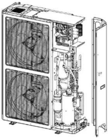 | Loosen the securing screws of the wires with a screwdriver.Remove the wires.NOTE:When removing the wires, mark the wire terminals corresponding to their color so as to avoid misconnection. |
| 2. Loosen the securing screws at the foot of compressor. | 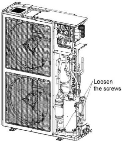 | Use a wrench to twist off the screw nuts at the foot of compressor. |
| 3. Break off the pipes that connecting to the compressor. | 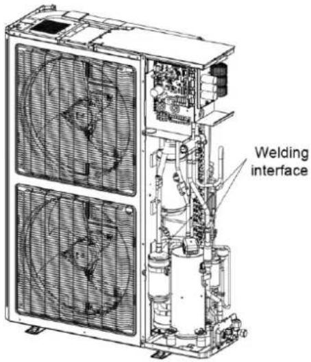 | Weld the pipes that are connected to the compressor.Then remove the pipes.NOTE:When welding the pipes, do not let the flame burn the other components. |
| 4. Remove the compressor from the chassis. | 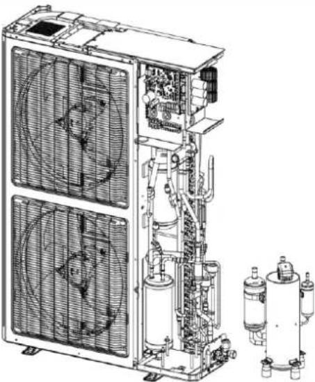 | Take out the compressor and replace it.NOTE:When replacing the compressor, avoid touching the nearby pipeline and components. |
| 5. Fix the new compressor back onto the chassis. | 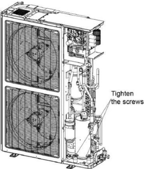 | After replacing the compressor, tighten up the screws at the foot of compressor. |
| 6. Connect the compressor suction port and exhause port with the pipes. | 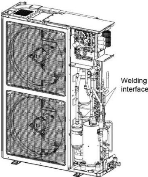 | Weld the compressor connection pipes and connect them to the compressor.NOTE:When replacing the compressor, avoid touching the nearby pipeline and components. |
| 7. Connect the compressor wires. | 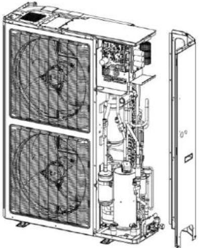 | Connect the compressor wires to the wire terminals on the top of compressor.NOTE: When connecting the wires, be sure to match the colors with the corresponding wire terminals. |
Model: MDUO18048060
| Removal of 4-way valve | ||
| NOTE:Before removing the 4-way valve, make sure refrigerant is fully discharged from the unit and power is cut off. | ||
| Step | Picture | Work instruction |
| 1. Take off the coil of the 4-way valve. | 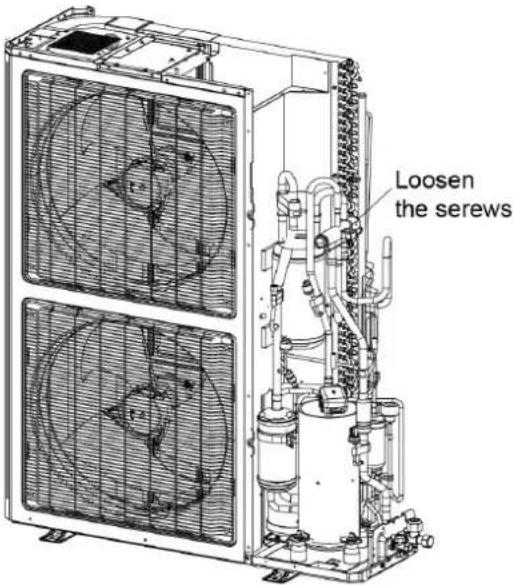 | • Carefully unscrew the screws of electromagnetic coil with a screwdriver. |
| 2. Break off the connection pipes from the 4-way valve. | 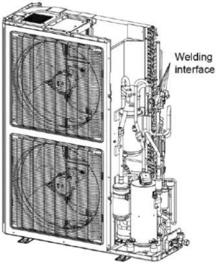 | Use a soldering gun to loosen the 4 joints on the 4-way valve and then remove the connection pipes.NOTE:When welding the pipes, the 4-way valve should be wrapped with wet cloth for cooling. Do not let the flame burn the other components. |
| 3. Replace the 4-way valve and connect it to the connection pipes. | 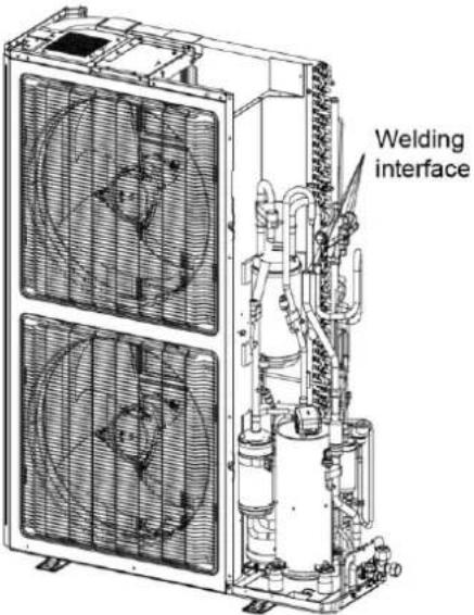 | Replace the 4-way valve and then use a soldering gun to weld the 4 joints of the 4-way valve.Note: When welding the pipes, the 4-way valve should be wrapped with wet cloth for cooling. Do not let the flame burn the other components. |
| 4. Install the coil of 4-way valve. | 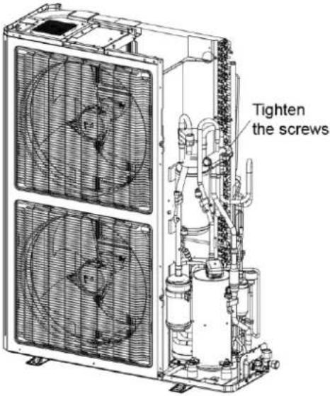 | Tighten the screws of the coil of 4-way valve with a screwdriver. |
Model: MDUO18048060
| Removal of fan and motor | ||
| NOTE: Before removing the fan, make sure power is cut off. | ||
| Step | Picture | Work instruction |
| 1. Remove the grill. | 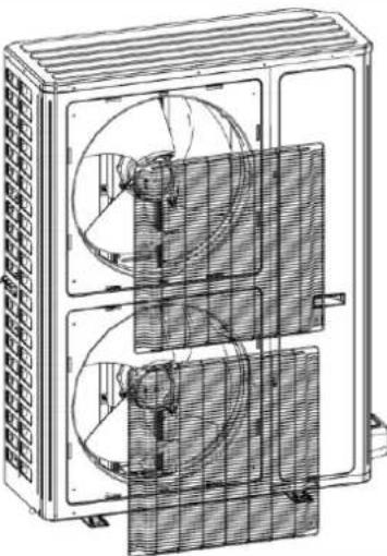 | Use a screwdriver to unscrew the two screws on the upper left and lower right corners. |
| 2. Remove the fan. |  | Use a wrench to remove the specialized nut and gasket of the fan.NOTE: Please keep the nut and gasket safe after removing them from the fan. |
| 3. Remove motor. | 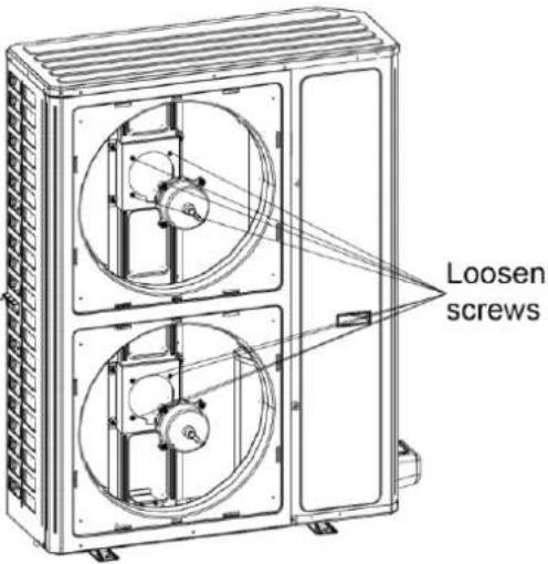 | Use a screwdriver to unscrew the bolt of motor.NOTE: Motor wire should be first removed from the electric box. |
| 4. Install the motor. | 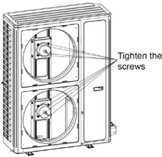 | Replace with a new motor.Then tighten up the screw bolt. |
| 5. Install the fan. | 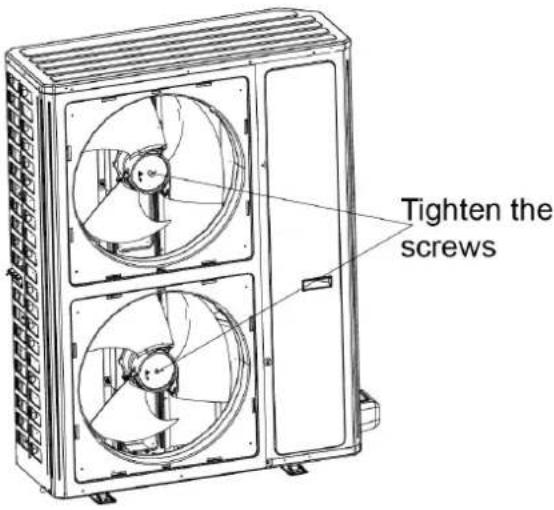 | Install the fan in place. Put on the gasket and use a wrench to secure the screw nut.NOTE:After installing the fan, turn the fan by hand to see if it can run normally. If not, please check for the reason. |
| 6. Install the grill. | 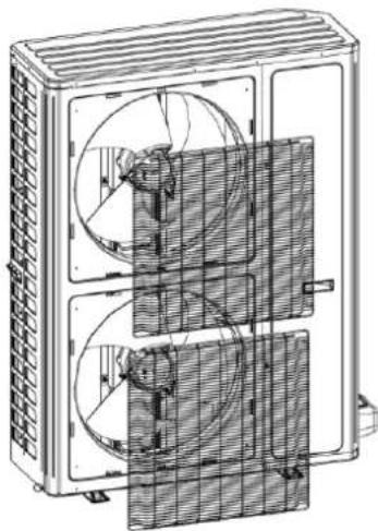 | After replacing the motor, use a screwdriver to tighten up the screw bolt that secures the motor. |
Model: MDUO18048060
| Removal of gas liquid separator | ||
| NOTE: Before removing the gas liquid separator, make sure there is no refrigerant in the pipeline and power is cut off. | ||
| Step | Picture | Work instruction |
| 1. Loosen the wire clamp at the bottom of the electric box and the screws of electric box. |  | Remove the upper, lower and front panels.Loosen the wire clamp at the bottom of the electric box.Unscrew the screws of electric box. |
| 2. Remove the electric box. | 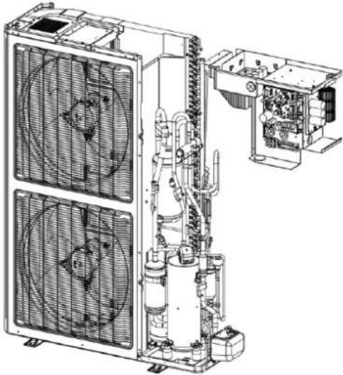 | The connection wires inside and outside the electric box should be removed.When removing the electric box, be careful to protect the components. |
| 3. Remove the compressor/gas liquid separator from the chassis. | 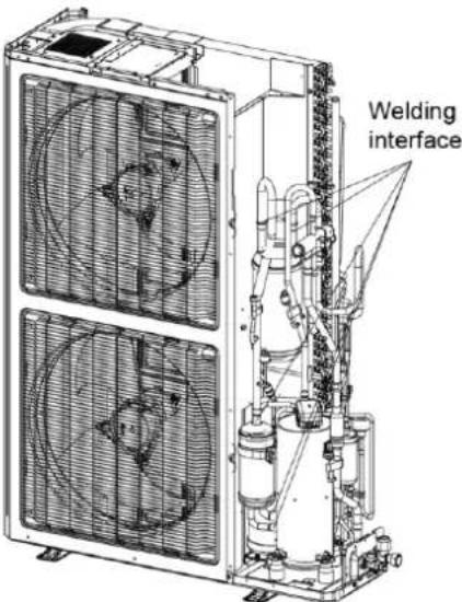 | Take away the compressor/gas liquid separator and replace with a new one.NOTE: When replacing the compressor/gas liquid separator, avoid touching the nearby pipeline and components. |
| 4. Install the new gas liquid separator | 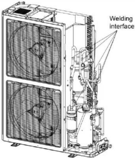 | Install the gas liquid separator by referring to the positions of entering and leaving pipes.Weld the 2 welding interfaces.Nitrogen welding: the pressure of nitrogen is 0.5 ± 0.1 kgf/cm^2 (relative pressure).NOTE: When welding the pipes, do not let the flame burn the other components.Tighten the screws of gas liquid separator. |
| 5. Secure the electric box and arrange the wires as required. | 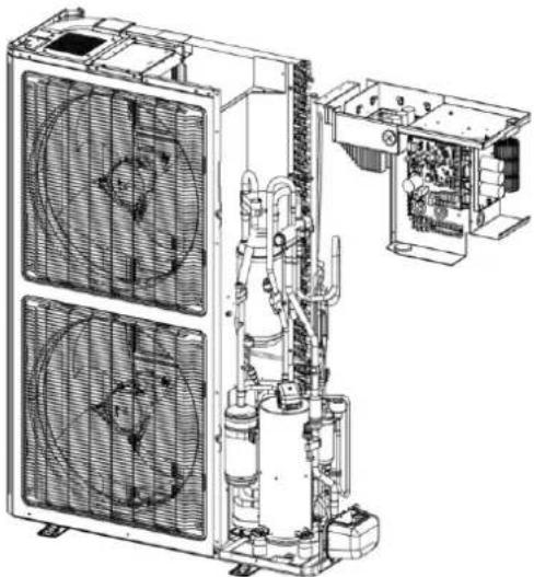 | Put the electric box back in place and tighten up the screws.Arrange the wires as original. |
| 6. Check and open the upper and side panels. | 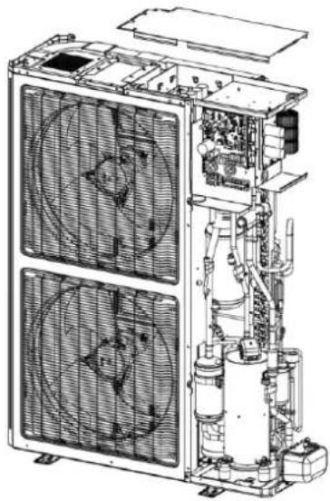 | Check whether each component and connection wire is well connected.If everything is OK, install the upper, left and right panels.Tighten up the screws. |
Model: MDUO18048060
| Removal of electronic expansion valve | ||
| NOTE:Before removing the electronic expansion valve, make sure there is no refrigerant in the pipeline and power is cut off. | ||
| Step | Picture | Work instruction |
| 1. Loosen the wire clamp at the bottom of the electric box and the screws of electric box. | 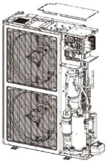 | Remove the upper, lower and front panels.Loosen the wire clamp at the bottom of the electric box.Unscrew the screws of electric box. |
| 2. Remove the electric box. | 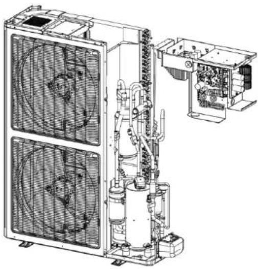 | The connection wires inside and outside the electric box should be removed.When removing the electric box, be careful to protect the components. |
| 3. Remove the electronic expansion valve. | 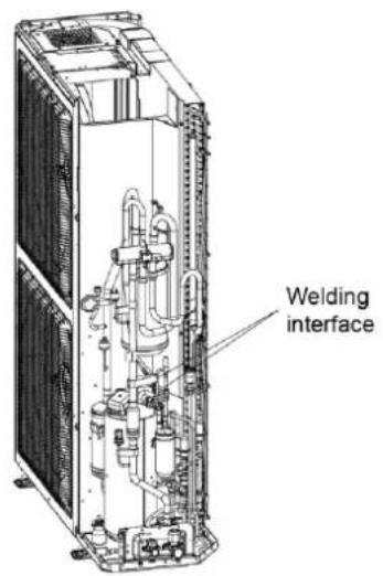 | Take off the coil of electronic expansion valve.Loosen the connection pipe of electronic expansion valve by welding. Then remove the connection pipe.NOTE:When welding the pipe, do not let the flame bunt the other components. |
| 4. Take out the electronic expansion valve. | 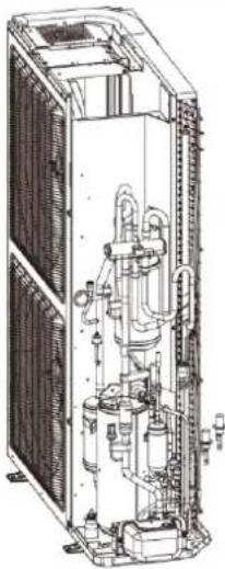 | Take out the electronic expansion valve. |
| 5. Install the new electronic expansion valve. | 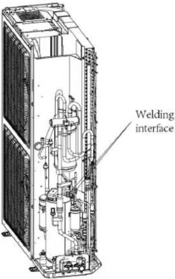 | Weld the connection pipe of electronic expansion valve.When welding the electronic expansion valve, the valve should be wrapped with wet cloth.Nitrogen welding: the pressure of nitrogen is 0.5 ± 0.1 kgf/ cm ^2 (relative pressure).NOTE: When welding the pipes, do not let the flame burn the other components.Install the coil of electronic expansion valve. |
| 6. Secure the electric box and arrange the wires as required. |  | Put the electric box back in place and tighten up the screws.Arrange the wires as original. |
| 7. Check and open the upper and side panels. | 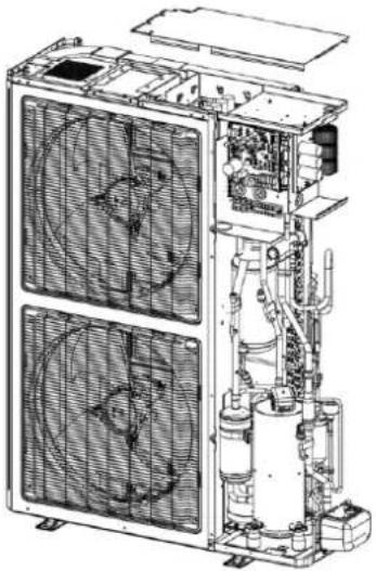 | Check whether each component and connection wire is well connected.If everything is OK, install the upper, left and right panels. Tighten up the screws. |
4.5.2 Removal of IDU Major Components
4.5.2.1 Airhandler Unit
| Disassembly and Assembly of the Electric Box | ||
| Step | Picture | Work instruction |
| 1. Remove the upper panel | 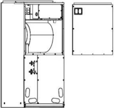 | Loosen screws around the upper panel with a screwdriver.Remove the upper panel away from the unit. |
| 2. Remove the electric box. | 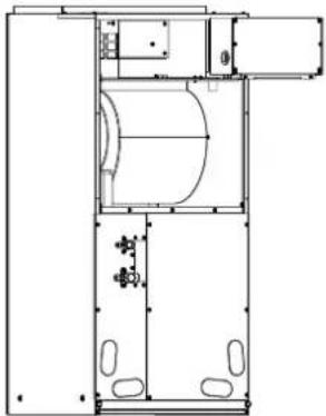 | Disconnect the power cord and control line from the wiring terminals, and then draw them out.Loosen screws around the electric box with a screwdriver.Remove the electric box from the unit. |
| 3. Remove the electric element. | 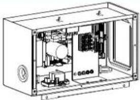 [IMAGE] [IMAGE]  | Disconnect the electric element from the wiring terminal.Loosen screws around the electric element with a screwdriver.Remove the electric element from the electric box. |
| 4. Mount the new electric element. | 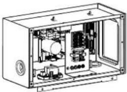  | Place the electric element at the proper position.Tighten the screws around the electric element with a screwdriver.Wire the electric element to the wiring terminal. |
| 5. Reinstall the electric box. |  | Place the electric box at the proper position.Tighten screws around the electric box with a screwdriver.Connect the power cord and control line properly.Reassemble the unit as before. |
| Disassembly and Assembly of the Fan Motor | ||
| Step | Picture | Work instruction |
| 1. Remove the upper panel. | 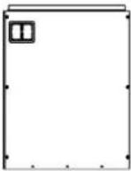 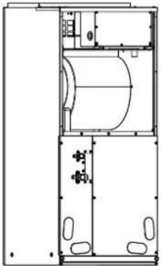 | Loosen screws round the upper panel with a screwdriver.Remove the upper panel from unit. |
| 2. Remove the fan. | 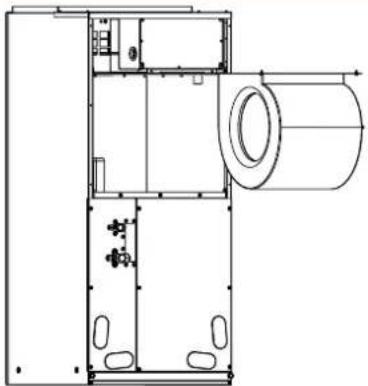 | · Disconnect the wires of the fan from the wiring terminal and draw them out.· Loosen screws located at the front of the fan with a screwdriver.· Remove the fan from the unit. |
| 3. Remove the motor. | 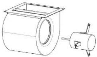 | · Loosen screws fixing the motor and fan blades.· Loosen screw bolts fixing the bracket.· Remove the motor rightward from the fan. |
| 4. Reinstall the fan. | 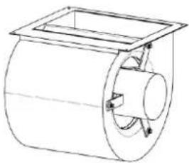 | · Place the motor at the proper position.· Tighten screws fixing the motor and fan blades.· Tighten screw bolts fixing the motor bracket.· After the installation, reassemble the unit as before. |
| Disassembly and Assembly of the Evaporator and Drain Pan | ||
| Step | Picture | Work instruction |
| 1. Remove the upper panel. | 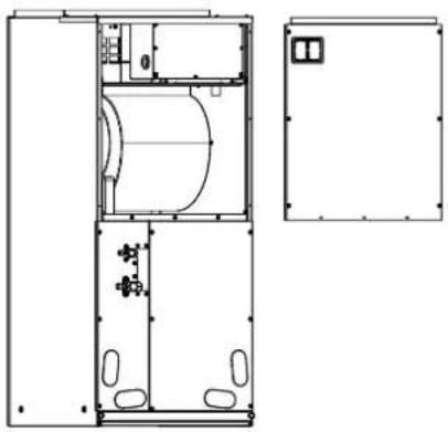 | Loosen screws round the upper panel with a screwdriver.Remove the upper panel from unit |
| 2. Remove the lower panel (1) and panel (2). | 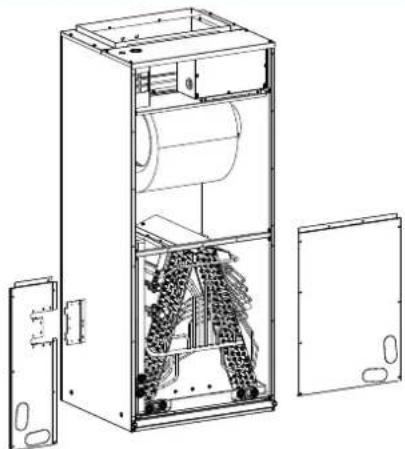 | Loosen screws round the lower panel with a screwdriver.Remove the lower panel from unit. |
| 3. Remove the enhanced frame if applicable. | 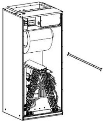 | Remove the screws from enhanced frame.Disassemble the enhanced frame from the unit. |
| 4. Remove the mounting plate of the drain pan. | 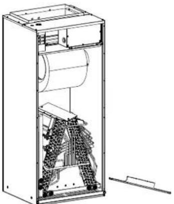 | Loosen screws at both side of the mounting plate with a screwdriver.Remove the mounting plate from the unit. |
| 5. Remove the primary drain pan. | 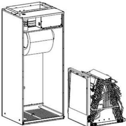 | Remove the primary drain pan from the unit. |
| 6. Remove the secondary drain pan. | 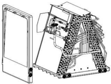 | Remove the secondary drain pan from the unit. |
| 7. Remove the evaporator. | 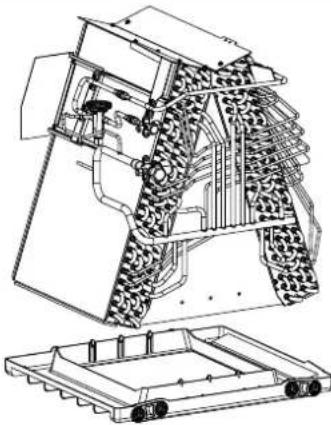 | Remove the evaporator away from the primary drain pan.Reassemble the unit as before. |
| Disassembly and Assembly of the Filter | ||
| Step | Picture | Work instruction |
| 1. Remove the mounting plate. | 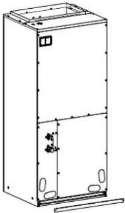 | ● Loosen screws fixing the mounting plate with a screwdriver.● Remove the mounting plate away from the unit. |
| 2. Remove the filter screen. | 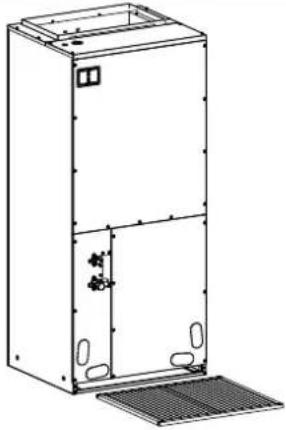 | Remove the filter screen away from the unit.After replacing the filter screen, reassemble the unit as before. |
4.6 Explosive View and Lists of Parts
4.6.1 ODU Explosive View and Lists of Parts
MDUO18024036 (Product code: 810512032921)
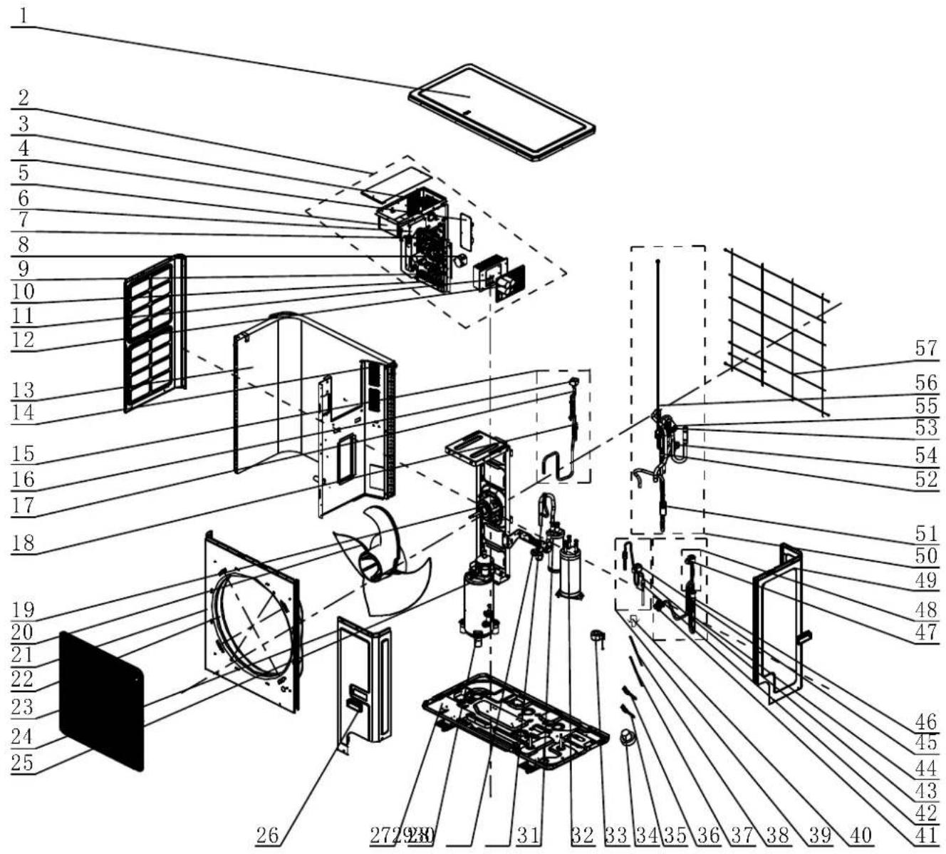
| No. | Material name |
| 1 | Coping |
| 2 | Electric Box Assy |
| 3 | PFC Inductance |
| 4 | Filter Board |
| 5 | Reactor Sub-Assy |
| 6 | Power Switch |
| 7 | Main Board |
| 8 | Inductance |
| 9 | Terminal Board |
| 10 | Terminal Board |
| 11 | Radiator |
| 12 | Main Board |
| 13 | Condenser Assy |
| 14 | Filter Sub-Assy |
| 15 | Electromagnetic Valve Sub-Assy |
| 16 | Magnet Coil (Electromagnetic Valve) |
| 17 | Electromagnetic Valve |
| 18 | Strainer |
| 19 | Brushless DC Motor |
| 20 | Axial Flow Fan |
| 21 | Cabinet |
| 22 | Diversion Circle |
| 23 | Front Grill |
| 24 | Front Side Plate |
| 25 | Compressor And Fittings |
| 26 | Handle |
| 27 | Chassis Assy |
| 28 | Foot |
| 29 | Cut Off Valve |
| 30 | Fusible Plug |
| 31 | Gas-liquid Separator |
| 32 | Accumulator |
| 33 | 4 Way Valve Coil |
| 34 | Drainage Hole Cap |
| 35 | Temperature Sensor |
| 36 | Temperature Sensor |
| 37 | Electrical Heater(Compressor) |
| 38 | Electrical Heater (Chassis) |
| 39 | Electric Expansion Valve Sub-Assy |
| 40 | Drainage Joint |
| 41 | Cut-Off Valve 3/8(N) |
| 42 | Strainer |
| 43 | Electric Expand Valve Fitting |
| 44 | One Way Valve |
| 45 | Electronic Expansion Valve |
| 46 | Strainer |
| 47 | Electric Expand Valve Fitting |
| 48 | Electric Expansion Valve Sub-Assy |
| 49 | Rear Side Plate |
| 50 | 4-Way Valve Assy |
| 51 | Silencer |
| 52 | Pressure Protect Switch |
| 53 | Filter |
| 54 | Pressure Protect Switch |
| 55 | 4-Way Valve |
| 56 | Pressure Sensor |
| 57 | Rear Grill |
MDUO18048060 (Product code: 810512032938)
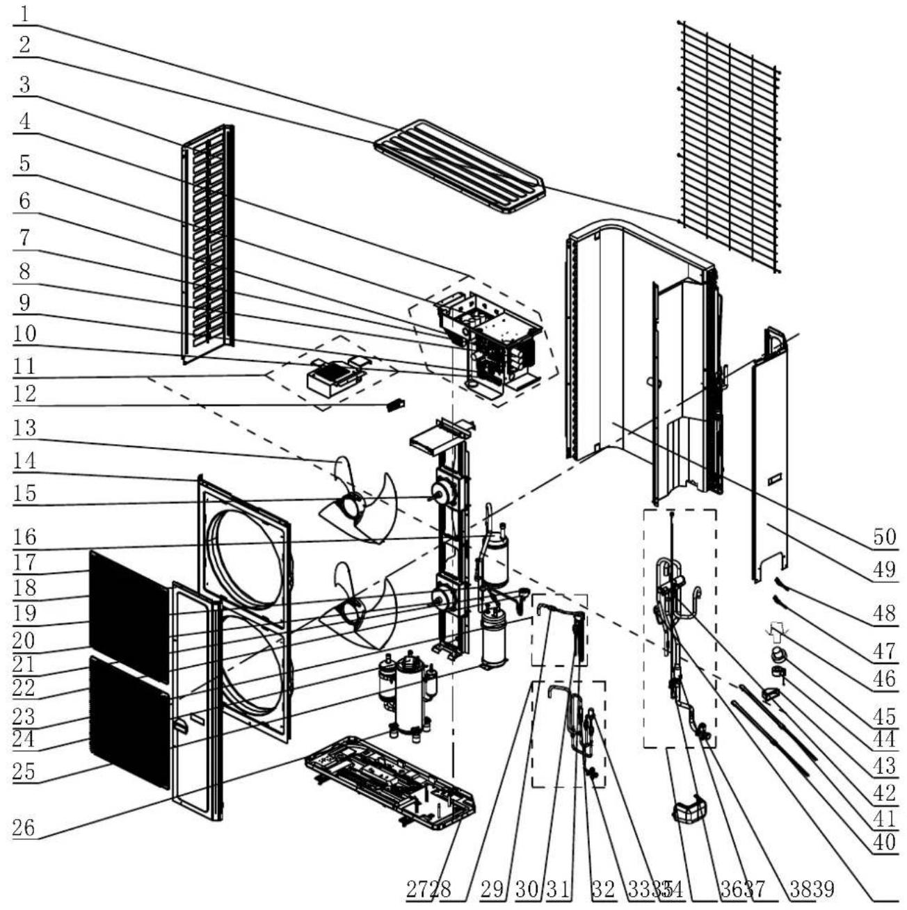
| No. | Material name |
| 1 | Coping |
| 2 | Rear Grill |
| 3 | Left Side Plate |
| 4 | Electric Box Assy |
| 5 | Drive Board |
| 6 | Radiator |
| 7 | Main Board |
| 8 | Filter Board |
| 9 | Terminal Board |
| 10 | Terminal Board |
| 11 | Inductance Box Assy |
| 12 | Handle |
| 13 | Axial Flow Fan |
| 14 | Cabinet |
| 15 | Brushless DC Motor |
| 16 | Gas-liquid Separator Sub-Assy |
| 17 | Front Grill |
| 18 | Front Side Plate |
| 19 | Pressure Protect Switch |
| 20 | Brushless DC Motor |
| 21 | Electromagnetic Valve |
| 22 | Electric Expand Valve Fitting |
| 23 | Electric Expansion Valve Sub-Assy |
| 24 | Compressor and Fittings |
| 25 | Accumulator |
| 26 | Foot |
| 27 | Chassis Sub-Assy |
| 28 | Cut Off Valve Sub-Assy |
| 29 | Strainer |
| 30 | Magnet Coil (Electromagnetic Valve) |
| 31 | Electric Expand Valve Fitting |
| 32 | One Way Valve |
| 33 | Cut-off Valve |
| 34 | Electronic Expansion Valve |
| 35 | 4-Way Valve Assy |
| 36 | Pressure Sensor |
| 37 | Strainer |
| 38 | Cut Off Valve 3/8 |
| 39 | Pressure Protect Switch |
| 40 | Electrical Heater(Compressor) |
| 41 | Electrical Heater(Compressor) |
| 42 | 4-Way Valve |
| 43 | Handle |
| 44 | 4 Way Valve Coil |
| 45 | Drainage Hole Cap |
| 46 | Drainage Joint |
| 47 | Temperature Sensor |
| 48 | Temperature Sensor |
| 49 | Rear Side Plate Sub-Assy |
| 50 | Condenser Assy |
4.6.2 IDU Explosive View and Lists of Parts
MDUI18024 MDUI18036 MDUI18048 MDUI18060
Product Code: 810512032945 810512032969 810512032976 810512032952
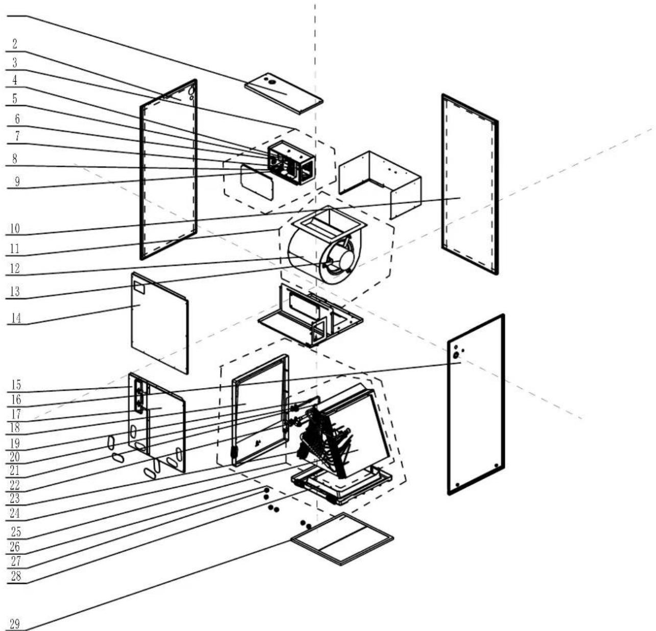
| No. | Material name |
| 1 | Coping |
| 2 | Left Side Plate |
| 3 | Electric Box Assy |
| 4 | Terminal Board |
| 5 | Transformer |
| 6 | Terminal Board |
| 7 | Main Board |
| 8 | Terminal Board |
| 9 | Pinboard |
| 10 | Rear Side Plate |
| 11 | Centrifugal Fan Assy |
| 12 | Motor For Centrifugal Fan |
| 13 | Brushless DC Motor |
| 14 | Top Cover Board Sub-Assy |
| 15 | Bottom Cover Plate Assy |
| 16 | Right Side Plate |
| 17 | Bottom Cover Plate Assy |
| 18 | Water Tray |
| 19 | Strainer |
| 20 | Cut-Off Valve 3/8(N) |
| 21 | Thermal Expansion Valve |
| 22 | Cut Off Valve |
| 23 | Evaporator Assy |
| 24 | Evaporator Assy |
| 25 | Evaporator Assy |
| 26 | Water Tray Assy |
| 27 | Choke Plug |
| 28 | Water Tray |
| 29 | Filter Sub-Assy |
Appendices
1 Resistance/Temperature Lists of Temperature Sensors
1.1 Voltage List of 15 KΩ Temperature Sensors (including ODU temperature sensors)
| Temperature (°C) | Resistance (kΩ) | Voltage (V) | Temperature (°C) | Resistance (kΩ) | Voltage (V) |
| -20 | 144 | 0.311 | 71 | 2.523 | 2.825 |
| -19 | 138.1 | 0.323 | 72 | 2.439 | 2.838 |
| -18 | 128.6 | 0.345 | 73 | 2.358 | 2.852 |
| -17 | 121.6 | 0.362 | 74 | 2.28 | 2.865 |
| -16 | 115 | 0.381 | 75 | 2.205 | 2.877 |
| -15 | 108.7 | 0.4 | 76 | 2.133 | 2.889 |
| -14 | 102.9 | 0.42 | 77 | 2.064 | 2.901 |
| -13 | 97.4 | 0.44 | 78 | 1.997 | 2.912 |
| -12 | 92.22 | 0.462 | 79 | 1.933 | 2.923 |
| -11 | 87.35 | 0.484 | 80 | 1.871 | 2.934 |
| -10 | 82.75 | 0.506 | 81 | 1.811 | 2.945 |
| -9 | 78.43 | 0.53 | 82 | 1.754 | 2.955 |
| -8 | 74.35 | 0.554 | 83 | 1.699 | 2.964 |
| -7 | 70.5 | 0.579 | 84 | 1.645 | 2.974 |
| -6 | 66.88 | 0.605 | 85 | 1.594 | 2.983 |
| -5 | 63.46 | 0.631 | 86 | 1.544 | 2.992 |
| -4 | 60.23 | 0.658 | 87 | 1.497 | 3.001 |
| -3 | 57.18 | 0.686 | 88 | 1.451 | 3.009 |
| -2 | 54.31 | 0.714 | 89 | 1.408 | 3.017 |
| -1 | 51.59 | 0.743 | 90 | 1.363 | 3.025 |
| 0 | 49.02 | 0.773 | 91 | 1.322 | 3.033 |
| 1 | 46.8 | 0.801 | 92 | 1.282 | 3.04 |
| 2 | 44.31 | 0.835 | 93 | 1.244 | 3.047 |
| 3 | 42.14 | 0.866 | 94 | 1.207 | 3.054 |
| 4 | 40.09 | 0.899 | 95 | 1.171 | 3.061 |
| 5 | 38.15 | 0.931 | 96 | 1.136 | 3.068 |
| 6 | 36.32 | 0.965 | 97 | 1.103 | 3.074 |
| 7 | 34.58 | 0.998 | 98 | 1.071 | 3.08 |
| 8 | 32.94 | 1.033 | 99 | 1.039 | 3.086 |
| 9 | 31.38 | 1.067 | 100 | 1.009 | 3.092 |
| 10 | 29.9 | 1.102 | 101 | 0.98 | 3.098 |
| 11 | 28.51 | 1.138 | 102 | 0.952 | 3.103 |
| 12 | 27.18 | 1.174 | 103 | 0.925 | 3.108 |
| 13 | 25.92 | 1.21 | 104 | 0.898 | 3.114 |
| 14 | 24.73 | 1.246 | 105 | 0.873 | 3.119 |
| 15 | 23.6 | 1.282 | 106 | 0.848 | 3.123 |
| 16 | 22.53 | 1.319 | 107 | 0.825 | 3.128 |
| 17 | 21.51 | 1.356 | 108 | 0.802 | 3.133 |
| 18 | 20.54 | 1.393 | 109 | 0.779 | 3.137 |
| 19 | 19.63 | 1.429 | 110 | 0.758 | 3.141 |
| 20 | 18.75 | 1.467 | 111 | 0.737 | 3.145 |
| 21 | 17.93 | 1.503 | 112 | 0.717 | 3.15 |
| 22 | 17.14 | 1.54 | 113 | 0.697 | 3.153 |
| 23 | 16.39 | 1.577 | 114 | 0.678 | 3.157 |
| 24 | 15.68 | 1.613 | 115 | 0.66 | 3.161 |
| 25 | 15 | 1.65 | 116 | 0.642 | 3.165 |
| 26 | 14.36 | 1.686 | 117 | 0.625 | 3.168 |
| 27 | 13.74 | 1.722 | 118 | 0.608 | 3.171 |
| 28 | 13.16 | 1.758 | 119 | 0.592 | 3.175 |
| 29 | 12.6 | 1.793 | 120 | 0.577 | 3.178 |
| 30 | 12.07 | 1.829 | 121 | 0.561 | 3.181 |
| 31 | 11.57 | 1.863 | 122 | 0.547 | 3.184 |
| 32 | 11.09 | 1.897 | 123 | 0.532 | 3.187 |
| 33 | 10.63 | 1.931 | 124 | 0.519 | 3.19 |
| 34 | 10.2 | 1.964 | 125 | 0.505 | 3.192 |
| 35 | 9.779 | 1.998 | 126 | 0.492 | 3.195 |
| 36 | 9.382 | 2.03 | 127 | 0.48 | 3.198 |
| 37 | 9.003 | 2.062 | 128 | 0.467 | 3.2 |
| 38 | 8.642 | 2.094 | 129 | 0.456 | 3.203 |
| 39 | 5.997 | 2.125 | 130 | 0.444 | 3.205 |
| 41 | 7.653 | 2.185 | 131 | 0.433 | 3.207 |
| 42 | 7.352 | 2.215 | 132 | 0.422 | 3.21 |
| 43 | 7.065 | 2.243 | 133 | 0.412 | 3.212 |
| 44 | 6.791 | 2.272 | 134 | 0.401 | 3.214 |
| 45 | 6.529 | 2.299 | 135 | 0.391 | 3.216 |
| 46 | 6.278 | 2.326 | 136 | 0.382 | 3.218 |
| 47 | 6.038 | 2.353 | 137 | 0.372 | 3.22 |
| 48 | 5.809 | 2.379 | 138 | 0.363 | 3.222 |
| 49 | 5.589 | 2.404 | 139 | 0.355 | 3.224 |
| 50 | 5.379 | 2.429 | 140 | 0.346 | 3.226 |
| 51 | 5.179 | 2.453 | 141 | 0.338 | 3.227 |
| 52 | 4.986 | 2.477 | 142 | 0.33 | 3.229 |
| 53 | 4.802 | 2.5 | 143 | 0.322 | 3.231 |
| 54 | 4.625 | 2.522 | 144 | 0.314 | 3.232 |
| 55 | 4.456 | 2.544 | 145 | 0.307 | 3.234 |
| 56 | 4.294 | 2.566 | 146 | 0.299 | 3.235 |
| 57 | 4.139 | 2.586 | 147 | 0.292 | 3.237 |
| 58 | 3.99 | 2.607 | 148 | 0.286 | 3.238 |
| 59 | 3.848 | 2.626 | 149 | 0.279 | 3.24 |
| 60 | 3.711 | 2.646 | 150 | 0.273 | 3.241 |
| 61 | 3.579 | 2.664 | 151 | 0.266 | 3.242 |
| 62 | 3.454 | 2.682 | 152 | 0.261 | 3.244 |
| 63 | 3.333 | 2.7 | 153 | 0.254 | 3.245 |
| 64 | 3.217 | 2.717 | 154 | 0.248 | 3.246 |
| 65 | 3.105 | 2.734 | 155 | 0.243 | 3.247 |
| 66 | 2.998 | 2.75 | 156 | 0.237 | 3.249 |
| 67 | 2.898 | 2.766 | 157 | 0.232 | 3.25 |
| 68 | 2.797 | 2.781 | 158 | 0.227 | 3.251 |
| 69 | 2.702 | 2.796 | 159 | 0.222 | 3.252 |
| 70 | 2.611 | 2.811 | 160 | 0.217 | 3.253 |
1.2 Voltage List of 20 KΩ Pipeline Temperature Sensors (including temperature sensors for defroster, IDU and ODU pipes)
| Temperature (°C) | Resistance (kΩ) | Voltage (V) | Temperature (°C) | Resistance (kΩ) | Voltage (V) |
| -30 | 361.8 | 0.173 | 66 | 3.998 | 2.75 |
| -29 | 339.8 | 0.183 | 67 | 3.861 | 2.766 |
| -28 | 319.2 | 0.195 | 68 | 3.729 | 2.781 |
| -27 | 300 | 0.206 | 69 | 3.603 | 2.796 |
| -26 | 282.2 | 0.218 | 70 | 3.481 | 2.811 |
| -25 | 265.5 | 0.231 | 71 | 3.364 | 2.825 |
| -24 | 249.9 | 0.245 | 72 | 3.252 | 2.838 |
| -23 | 235.3 | 0.259 | 73 | 3.144 | 2.852 |
| -22 | 221.6 | 0.273 | 74 | 3.04 | 2.865 |
| -21 | 208.9 | 0.288 | 75 | 2.94 | 2.877 |
| -20 | 196.9 | 0.304 | 76 | 2.844 | 2.889 |
| -19 | 181.4 | 0.328 | 77 | 2.752 | 2.901 |
| -18 | 171.4 | 0.345 | 78 | 2.663 | 2.912 |
| -17 | 162.1 | 0.362 | 79 | 2.577 | 2.923 |
| -16 | 153.3 | 0.381 | 80 | 2.495 | 2.934 |
| -15 | 145 | 0.4 | 81 | 2.415 | 2.944 |
| -14 | 137.2 | 0.42 | 82 | 2.339 | 2.954 |
| -13 | 129.9 | 0.44 | 83 | 2.265 | 2.964 |
| -12 | 123 | 0.462 | 84 | 2.194 | 2.974 |
| -11 | 116.5 | 0.484 | 85 | 2.125 | 2.983 |
| -10 | 110.3 | 0.507 | 86 | 2.059 | 2.992 |
| -9 | 104.6 | 0.53 | 87 | 1.996 | 3.001 |
| -8 | 99.13 | 0.554 | 88 | 1.934 | 3.009 |
| -7 | 94 | 0.579 | 89 | 1.875 | 3.017 |
| -6 | 89.17 | 0.605 | 90 | 1.818 | 3.025 |
| -5 | 84.61 | 0.631 | 91 | 1.763 | 3.033 |
| -4 | 80.31 | 0.658 | 92 | 1.71 | 3.04 |
| -3 | 76.24 | 0.686 | 93 | 1.658 | 3.047 |
| -2 | 72.41 | 0.714 | 94 | 1.609 | 3.054 |
| -1 | 68.79 | 0.743 | 95 | 1.561 | 3.061 |
| 0 | 65.37 | 0.773 | 96 | 1.515 | 3.068 |
| 1 | 62.13 | 0.804 | 97 | 1.47 | 3.074 |
| 2 | 59.08 | 0.835 | 98 | 1.427 | 3.08 |
| 3 | 56.19 | 0.866 | 99 | 1.386 | 3.086 |
| 4 | 53.46 | 0.898 | 100 | 1.346 | 3.092 |
| 5 | 50.87 | 0.931 | 101 | 1.307 | 3.098 |
| 6 | 48.42 | 0.965 | 102 | 1.269 | 3.103 |
| 7 | 46.11 | 0.998 | 103 | 1.233 | 3.108 |
| 8 | 43.92 | 1.033 | 104 | 1.198 | 3.114 |
| 9 | 41.84 | 1.067 | 105 | 1.164 | 3.119 |
| 10 | 39.87 | 1.102 | 106 | 1.131 | 3.123 |
| 11 | 38.01 | 1.138 | 107 | 1.099 | 3.128 |
| 12 | 36.24 | 1.174 | 108 | 1.069 | 3.133 |
| 13 | 34.57 | 1.209 | 109 | 1.039 | 3.137 |
| 14 | 32.98 | 1.246 | 110 | 1.01 | 3.141 |
| 15 | 31.47 | 1.282 | 111 | 0.9825 | 3.145 |
| 16 | 30.04 | 1.319 | 112 | 0.9556 | 3.15 |
| 17 | 28.68 | 1.356 | 113 | 0.9295 | 3.153 |
| 18 | 27.39 | 1.393 | 114 | 0.9043 | 3.157 |
| 19 | 26.17 | 1.429 | 115 | 0.8799 | 3.161 |
| 20 | 25.01 | 1.466 | 116 | 0.8562 | 3.165 |
| 21 | 23.9 | 1.503 | 117 | 0.8333 | 3.168 |
| 22 | 22.85 | 1.54 | 118 | 0.8111 | 3.171 |
| 23 | 21.85 | 1.577 | 119 | 0.7895 | 3.175 |
| 24 | 20.9 | 1.614 | 120 | 0.7687 | 3.178 |
| 25 | 20 | 1.65 | 121 | 0.7485 | 3.181 |
| 26 | 19.14 | 1.686 | 122 | 0.7289 | 3.184 |
| 27 | 18.32 | 1.722 | 123 | 0.7099 | 3.187 |
| 28 | 17.55 | 1.758 | 124 | 0.6915 | 3.19 |
| 29 | 16.8 | 1.793 | 125 | 0.6736 | 3.192 |
| 30 | 16.1 | 1.828 | 126 | 0.6563 | 3.195 |
| 31 | 15.43 | 1.863 | 127 | 0.6395 | 3.198 |
| 32 | 14.79 | 1.897 | 128 | 0.6232 | 3.2 |
| 33 | 14.18 | 1.931 | 129 | 0.6074 | 3.203 |
| 34 | 13.59 | 1.965 | 130 | 0.5921 | 3.205 |
| 35 | 13.04 | 1.998 | 131 | 0.5772 | 3.207 |
| 36 | 12.51 | 2.03 | 132 | 0.5627 | 3.21 |
| 37 | 12 | 2.063 | 133 | 0.5487 | 3.212 |
| 38 | 11.52 | 2.094 | 134 | 0.5351 | 3.214 |
| 39 | 11.06 | 2.125 | 135 | 0.5219 | 3.216 |
| 40 | 10.62 | 2.155 | 136 | 0.509 | 3.218 |
| 41 | 10.2 | 2.185 | 137 | 0.4966 | 3.22 |
| 42 | 9.803 | 2.215 | 138 | 0.4845 | 3.222 |
| 43 | 9.42 | 2.243 | 139 | 0.4727 | 3.224 |
| 44 | 9.054 | 2.272 | 140 | 0.4613 | 3.226 |
| 45 | 8.705 | 2.299 | 141 | 0.4502 | 3.227 |
| 46 | 8.37 | 2.326 | 142 | 0.4394 | 3.229 |
| 47 | 8.051 | 2.353 | 143 | 0.4289 | 3.231 |
| 48 | 7.745 | 2.379 | 144 | 0.4187 | 3.232 |
| 49 | 7.453 | 2.404 | 145 | 0.4088 | 3.234 |
| 50 | 7.173 | 2.429 | 146 | 0.3992 | 3.235 |
| 51 | 6.905 | 2.453 | 147 | 0.3899 | 3.237 |
| 52 | 6.648 | 2.477 | 148 | 0.3808 | 3.238 |
| 53 | 6.403 | 2.5 | 149 | 0.3719 | 3.24 |
| 54 | 6.167 | 2.522 | 150 | 0.3633 | 3.241 |
| 55 | 5.942 | 2.544 | 151 | 0.3549 | 3.242 |
| 56 | 5.726 | 2.565 | 152 | 0.3468 | 3.244 |
| 57 | 5.519 | 2.586 | 153 | 0.3389 | 3.245 |
| 58 | 5.32 | 2.607 | 154 | 0.3312 | 3.246 |
| 59 | 5.13 | 2.626 | 155 | 0.3237 | 3.247 |
| 60 | 4.948 | 2.646 | 156 | 0.3164 | 3.249 |
| 61 | 4.773 | 2.664 | 157 | 0.3093 | 3.25 |
| 62 | 4.605 | 2.682 | 158 | 0.3024 | 3.251 |
| 63 | 4.443 | 2.7 | 159 | 0.2956 | 3.252 |
| 64 | 4.289 | 2.717 | 160 | 0.2891 | 3.253 |
| 65 | 4.14 | 2.734 |
1.3 Voltage List of 50 KΩ Discharge Temperature Sensors (including discharge air temperature sensor)
| Temperature (°C) | Resistance (kΩ) | Voltage (V) | Temperature (°C) | Resistance (kΩ) | Voltage (V) |
| -30 | 911.56 | 0.036 | 61 | 11.736 | 1.518 |
| -29 | 853.66 | 0.038 | 62 | 11.322 | 1.548 |
| -28 | 799.98 | 0.041 | 63 | 10.925 | 1.577 |
| -27 | 750.18 | 0.043 | 64 | 10.544 | 1.606 |
| -26 | 703.92 | 0.046 | 65 | 10.178 | 1.635 |
| -25 | 660.93 | 0.049 | 66 | 9.8269 | 1.664 |
| -24 | 620.94 | 0.052 | 67 | 9.4896 | 1.693 |
| -23 | 583.72 | 0.056 | 68 | 9.1655 | 1.722 |
| -22 | 549.04 | 0.059 | 69 | 8.9542 | 1.741 |
| -21 | 516.71 | 0.063 | 70 | 8.5551 | 1.778 |
| -20 | 486.55 | 0.066 | 71 | 5.9676 | 1.806 |
| -19 | 458.4 | 0.07 | 72 | 7.9913 | 1.834 |
| -18 | 432.1 | 0.075 | 73 | 7.7257 | 1.862 |
| -17 | 407.51 | 0.079 | 74 | 7.4702 | 1.889 |
| -16 | 384.51 | 0.084 | 75 | 7.2245 | 1.916 |
| -15 | 362.99 | 0.088 | 76 | 6.9882 | 1.943 |
| -14 | 342.83 | 0.094 | 77 | 6.7608 | 1.969 |
| -13 | 323.94 | 0.099 | 78 | 6.542 | 1.995 |
| -12 | 306.23 | 0.104 | 79 | 6.3315 | 2.021 |
| -11 | 289.61 | 0.11 | 80 | 6.1288 | 2.046 |
| -10 | 274.02 | 0.116 | 81 | 5.9336 | 2.071 |
| -9 | 259.37 | 0.123 | 82 | 5.7457 | 2.096 |
| -8 | 245.61 | 0.129 | 83 | 5.5647 | 2.12 |
| -7 | 232.67 | 0.136 | 84 | 5.3903 | 2.144 |
| -6 | 220.5 | 0.143 | 85 | 5.2223 | 2.168 |
| -5 | 209.05 | 0.151 | 86 | 5.0605 | 2.191 |
| -4 | 195.97 | 0.158 | 87 | 4.9044 | 2.214 |
| -3 | 188.12 | 0.167 | 88 | 4.7541 | 2.237 |
| -2 | 178.65 | 0.175 | 89 | 4.6091 | 2.259 |
| -1 | 169.68 | 0.184 | 90 | 4.4693 | 2.281 |
| 0 | 161.02 | 0.193 | 91 | 4.3345 | 2.302 |
| 1 | 153 | 0.202 | 92 | 4.2044 | 2.323 |
| 2 | 145.42 | 0.212 | 93 | 4.0789 | 2.344 |
| 3 | 135.96 | 0.223 | 94 | 3.9579 | 2.364 |
| 4 | 131.5 | 0.233 | 95 | 3.841 | 2.384 |
| 5 | 126.17 | 0.242 | 96 | 3.7283 | 2.404 |
| 6 | 119.08 | 0.256 | 97 | 3.6194 | 2.423 |
| 7 | 113.37 | 0.267 | 98 | 3.5143 | 2.442 |
| 8 | 107.96 | 0.28 | 99 | 3.4128 | 2.46 |
| 9 | 102.85 | 0.292 | 100 | 3.3147 | 2.478 |
| 10 | 98.006 | 0.306 | 101 | 3.22 | 2.496 |
| 11 | 93.42 | 0.319 | 102 | 3.1285 | 2.514 |
| 12 | 89.075 | 0.333 | 103 | 3.0401 | 2.531 |
| 13 | 84.956 | 0.348 | 104 | 2.9547 | 2.547 |
| 14 | 81.052 | 0.362 | 105 | 2.8721 | 2.564 |
| 15 | 77.349 | 0.378 | 106 | 2.7922 | 2.58 |
| 16 | 73.896 | 0.393 | 107 | 2.715 | 2.595 |
| 17 | 70.503 | 0.41 | 108 | 2.6404 | 2.611 |
| 18 | 67.338 | 0.427 | 109 | 2.5682 | 2.626 |
| 19 | 64.333 | 0.444 | 110 | 2.4983 | 2.64 |
| 20 | 61.478 | 0.462 | 111 | 2.4308 | 2.655 |
| 21 | 58.766 | 0.48 | 112 | 2.3654 | 2.669 |
| 22 | 56.189 | 0.499 | 113 | 2.3021 | 2.682 |
| 23 | 53.738 | 0.518 | 114 | 2.2409 | 2.696 |
| 24 | 51.408 | 0.537 | 115 | 2.1816 | 2.709 |
| 25 | 49.191 | 0.558 | 116 | 2.1242 | 2.722 |
| 26 | 47.082 | 0.578 | 117 | 2.0686 | 2.734 |
| 27 | 45.074 | 0.599 | 118 | 2.0148 | 2.747 |
| 28 | 43.163 | 0.621 | 119 | 1.9626 | 2.759 |
| 29 | 41.313 | 0.643 | 120 | 1.9123 | 2.77 |
| 30 | 39.61 | 0.665 | 121 | 1.8652 | 2.781 |
| 31 | 37.958 | 0.688 | 122 | 1.8158 | 2.793 |
| 32 | 36.384 | 0.711 | 123 | 1.7698 | 2.804 |
| 33 | 34.883 | 0.735 | 124 | 1.7253 | 2.814 |
| 34 | 33.453 | 0.759 | 125 | 1.6821 | 2.825 |
| 35 | 32.088 | 0.784 | 126 | 1.6402 | 2.835 |
| 36 | 30.787 | 0.809 | 127 | 1.5996 | 2.845 |
| 37 | 29.544 | 0.835 | 128 | 1.5602 | 2.855 |
| 38 | 28.359 | 0.86 | 129 | 1.522 | 2.864 |
| 39 | 27.227 | 0.886 | 130 | 1.485 | 2.873 |
| 40 | 26.147 | 0.913 | 131 | 1.449 | 2.882 |
| 41 | 25.114 | 0.94 | 132 | 1.4141 | 2.891 |
| 42 | 24.128 | 0.967 | 133 | 1.3803 | 2.9 |
| 43 | 23.186 | 0.994 | 134 | 1.3474 | 2.908 |
| 44 | 22.286 | 1.022 | 135 | 1.3155 | 2.916 |
| 45 | 21.425 | 1.05 | 136 | 1.2846 | 2.924 |
| 46 | 20.601 | 1.078 | 137 | 1.2545 | 2.932 |
| 47 | 19.814 | 1.107 | 138 | 1.2233 | 2.94 |
| 48 | 19.061 | 1.136 | 139 | 1.1969 | 2.947 |
| 49 | 18.34 | 1.164 | 140 | 1.1694 | 2.955 |
| 50 | 17.651 | 1.193 | 141 | 1.1476 | 2.96 |
| 51 | 16.99 | 1.223 | 142 | 1.1166 | 2.969 |
| 52 | 16.358 | 1.252 | 143 | 1.0913 | 2.975 |
| 53 | 15.753 | 1.281 | 144 | 1.0667 | 2.982 |
| 54 | 15.173 | 1.311 | 145 | 1.0429 | 2.988 |
| 55 | 14.618 | 1.34 | 146 | 1.0197 | 2.995 |
| 56 | 14.085 | 1.37 | 147 | 0.9971 | 3.001 |
| 57 | 13.575 | 1.4 | 148 | 0.9752 | 3.007 |
| 58 | 13.086 | 1.429 | 149 | 0.9538 | 3.013 |
| 59 | 12.617 | 1.459 | 150 | 0.9331 | 3.018 |
| 60 | 12.368 | 1.475 | - | - | - |
2 Temperature/Pressure List of Refrigerant
| R410A | |||||||
| Temperature | Pressure | Temperature | Pressure | Temperature | Pressure | ||
| °C | kPa | °C | kPa | °C | kPa | ||
| -30 | 275 | 0 | 803 | 30 | 1880 | ||
| -29 | 286 | 1 | 823 | 31 | 1910 | ||
| -28 | 298 | 2 | 851 | 32 | 1960 | ||
| -27 | 311 | 3 | 879 | 33 | 2030 | ||
| -26 | 324 | 4 | 903 | 34 | 2080 | ||
| -25 | 334 | 5 | 937 | 35 | 2130 | ||
| -24 | 348 | 6 | 962 | 36 | 2180 | ||
| -23 | 363 | 7 | 994 | 37 | 2240 | ||
| -22 | 375 | 8 | 1020 | 38 | 2290 | ||
| -21 | 391 | 9 | 1050 | 39 | 2350 | ||
| -20 | 404 | 10 | 1090 | 40 | 2410 | ||
| -19 | 424 | 11 | 1110 | 41 | 2460 | ||
| -18 | 435 | 12 | 1150 | 42 | 2510 | ||
| -17 | 453 | 13 | 1180 | 43 | 2580 | ||
| -16 | 468 | 14 | 1220 | 44 | 2650 | ||
| -15 | 483 | 15 | 1250 | 45 | 2710 | ||
| -14 | 504 | 16 | 1280 | 46 | 2770 | ||
| -13 | 520 | 17 | 1320 | 47 | 2840 | ||
| -12 | 538 | 18 | 1350 | 48 | 2910 | ||
| -11 | 556 | 19 | 1400 | 49 | 2980 | ||
| -10 | 579 | 20 | 1440 | 50 | 3050 | ||
| -9 | 598 | 21 | 1470 | 51 | 3100 | ||
| -8 | 618 | 22 | 1520 | 52 | 3180 | ||
| -7 | 639 | 23 | 1560 | 53 | 3250 | ||
| -6 | 660 | 24 | 1600 | 54 | 3320 | ||
| -5 | 682 | 25 | 1640 | 55 | 3400 | ||
| -4 | 705 | 26 | 1680 | 56 | 3480 | ||
| -3 | 728 | 27 | 1730 | 57 | 3540 | ||
| -2 | 752 | 28 | 1780 | 58 | 3630 | ||
| -1 | 777 | 29 | 1820 | 59 | 3720 | ||
3 Operation Tools
The following tools will be used: 1) Liquid-level gauge; 2) Screwdriver; 3) Electric driven rotary hammer; 4) Drill; 5) Pipe expander; 6) Torque wrench; 7) Open-end wrench; 8) Pipe cutter; 9) Leak detector; 10) Vacuum pump; 11) Pressure gauge; 12) Universal meter; 13) Hexagon wrench; 14) Tapeline.

natural_image
Abstract blue logo design featuring stylized animal-like figures and a bird, no text or symbols present.MRCOOL®
COMFORT MADE SIMPLE
- MRCOOL®
- COMFORT MADE SIMPLE
- DC INVERTER HEAT PUMP CONDENSING UNIT SERVICE MANUAL
- Foreword
- Safety Notice
- CONTENTS
- Product Introduction ....3
- Control....6
- Troubleshooting....14
- Maintenance....55
- Appendices 110
- Resistance/Temperature Lists of Temperature Sensors .... 110
- Temperature/Pressure List of Refrigerant 117
- Operation Tools 117
- Safety Notice on Maintenance
- PROHIBITED:
- WARNING:
- NOTICE:
- OBSERVED:
- Safety Notice on Operation
- Product Introduction
- Lists of Units
- List of Outdoor Units
- List of Indoor Units
- Electrical Parameters
- Control
- Operation Mode
- Cooling Mode
- Heating Mode
- Control Mode
- Based Control
- Compressor Control
- EXV Control
- Outdoor Fan Control
- 4-way Valve Control
- Special Control
- Defrosting Control
- Oil Return Control
- Protection Control
- High Pressure Protection Control
- Low Pressure Protection Control
- High Temperature Prevention Control
- Discharge High Temperature Protection Control
- Functions
- Set Capacity Dip Switch
- Set Defrost Mode
- Set Operating Mode
- Set Indoor Fan Speed
- Forced Defrost Control
- Refrigerant Recovery Control
- Forced Operation Control
- Thermostat Functions
- Troubleshooting
- Wiring Diagrams
- Wiring Diagrams for OUTDOOR UNITS
- PCB Layout
- Interface
- IPM, PFC Testing Method
- Method of Testing IPM Module
- Method of Testing PFC Module Short Circuit
- Error Code
- Troubleshooting
- "E1" Compressor High Pressure Protection
- "E3" Compressor Low-pressure Protection, Refrigerant Shortage
- Protection, Refrigerant Recovery Mode
- Possible reason:
- Troubleshooting:
- "F2" Condenser Temperature Sensor Error
- NOTE:
- "F3" Outdoor Ambient Temperature Sensor Error
- Error judgment condition and method:
- "F4" Discharge Temperature Sensor Error
- "F6" ODU Tube Temperature Sensor Error
- 3.4.8“EE” ODU Memory Chip Error
- "H4" Overload
- "H5" IPM Protection
- "H6" DC Fan Error
- "H7" Driver Out-of-Step Protection
- "HC" PFC Protection
- "Lc" Startup Failure
- "P0" Driver Reset Protection
- "P5" Over-Current Protection
- "P6" Master Control and Driver Communication Error
- "P7" Driver Module Sensor Error
- "P8" Driver Module High Temperature Protection
- "PA" AC Current Protection
- "Pc" Driver Current Error
- "PL" Bus Low-Voltage Protection
- "PH" Bus High-Voltage Protection
- "PU" Charge Loop Error
- "ee" Drive Memory Chip Error
- "e1" High Pressure Sensor Error
- "C4" ODU Jumper Cap Error
- Failures Not Caused by Errors
- Maintenance
- System Diagram
- Connection Pipe Vacuum Pumping
- Refrigerant Charging
- Maintenance of Major Components
- Replacement of thermostat
- How to replace the compressor
- Diagnosis of compressor failure
- Step 2:
- Step 3:
- Electronic expansion valve:
- 4-way valve:
- Replacement of compressor
- Prepare relevant tools
- Step 2: Disconnect power
- Step 3: Neaten the electric components
- Step 4: Discharge refrigerant
- Step 5: Detach the compressor
- Step 7: Clear the pipeline
- How to replace the drive module of compressor
- Removal of Major Components
- Removal of ODU Major Components
- Removal of IDU Major Components
- Airhandler Unit
- Explosive View and Lists of Parts
- ODU Explosive View and Lists of Parts
- IDU Explosive View and Lists of Parts
- Appendices
- Resistance/Temperature Lists of Temperature Sensors
- Voltage List of 15 KΩ Temperature Sensors (including ODU temperature sensors)
- Voltage List of 20 KΩ Pipeline Temperature Sensors (including temperature sensors for defroster, IDU and ODU pipes)
- Voltage List of 50 KΩ Discharge Temperature Sensors (including discharge air temperature sensor)
- Operation Tools
Brand : MRCOOL
Model : MDUO18048060
Category : Air Conditioning