SURFboard SBG6400 - Router Arris - Free user manual and instructions
Find the device manual for free SURFboard SBG6400 Arris in PDF.

| Product Type | DOCSIS 3.0 Cable Modem + Router + Voice Gateway |
| Brand | Arris |
| Model | SURFboard SBG6400 |
| Dimensions | 7.5 x 5.5 x 1.5 inches (19.1 x 14 x 3.8 cm) |
| Weight | 1.1 lbs (0.5 kg) |
| Power Supply | 12V DC, 1A (12W) |
| Wireless Standard | 802.11b/g/n (2.4 GHz) |
| Max Wireless Speed | 300 Mbps |
| WAN Connection | DOCSIS 3.0 (8x4 channel bonding) |
| Ethernet Ports | 4 x Gigabit LAN 10/100/1000 |
| Voice Ports | 2 x RJ-11 (Phone) with VoIP |
| USB Ports | 1 x USB 2.0 (for storage sharing) |
| Antennas | 2 x internal |
| Security | WPA/WPA2, SPI Firewall, MAC Filtering, DoS Protection |
| LED Indicators | Power, Online, Voice, WiFi, LAN x4, USB |
| Operating Temperature | 32°F to 104°F (0°C to 40°C) |
| Certifications | FCC, IC, CE |
| Cleaning Instructions | Unplug and wipe with a dry soft cloth. Do not use liquids. |
| Spare Parts Availability | Power adapter and Ethernet cables available from authorized resellers. |
| Repairability | Not user-serviceable. Contact ISP or Arris support. |
Frequently Asked Questions - SURFboard SBG6400 Arris
User questions about SURFboard SBG6400 Arris
0 question about this device. Answer the ones you know or ask your own.
Ask a new question about this device
Download the instructions for your Router in PDF format for free! Find your manual SURFboard SBG6400 - Arris and take your electronic device back in hand. On this page are published all the documents necessary for the use of your device. SURFboard SBG6400 by Arris.
USER MANUAL SURFboard SBG6400 Arris
natural_image
Illustration of a residential neighborhood with houses, roads, and power lines under a blue sky (no text or symbols)SURFboard® SBG6400 DOCSIS 3.0 Wireless Gateway
User Guide
© 2015 ARRIS Enterprises, Inc. All rights reserved.
No part of this publication may be reproduced or transmitted in any form or by any means or used to make any derivative work (such as translation, transformation, or adaptation) without written permission from ARRIS Enterprises, Inc. ("ARRIS"). ARRIS reserves the right to revise this publication and to make changes in content from time to time without obligation on the part of ARRIS to provide notification of such revision or change.
ARRIS, SURFboard, and the ARRIS logo are all trademarks or registered trademarks of ARRIS Enterprises, Inc. Other trademarks and trade names may be used in this document to refer to either the entities claiming the marks and the names of their products. ARRIS disclaims proprietary interest in the marks and names of others.
Wi-Fi Alliance ^® , Wi-Fi ^® , the Wi-Fi logo, the Wi-Fi CERTIFIED logo, Wi-Fi Protected Access ^® (WPA), the Wi-Fi Protected Setup logo, and WMM ^® are registered trademarks of Wi-Fi Alliance. Wi-Fi Protected Setup ^™ , Wi-Fi Multimedia ^™ , and WPA2 ^™ are trademarks of Wi-Fi Alliance.
ARRIS provides this guide without warranty of any kind, implied or expressed, including, but not limited to, the implied warranties of merchantability and fitness for a particular purpose. ARRIS may make improvements or changes in the product(s) described in this manual at any time.
The capabilities, system requirements and/or compatibility with third-party products described herein are subject to change without notice.
Contents
Safety and Regulatory Information......viii
Getting Started....1
Introduction ....1
In The Box....1
Additional Items Needed (Not Included) 2
System Requirements....2
Contact Information....2
Product Overview....3
Front Panel 3
Wi-Fi Protected Setup™ (WPS)....4
Rear Panel....5
Gateway Label 6
Installing the Gateway....7
Connect the SBG6400 to Your Computer ....7
Establish an Internet Connection....8
Setting Up a Wireless Network Connection....9
Launch the SBG6400 Quick Start Wizard 9
Set Up a Wireless Network Using Your Computer....15
Quick Connect Using the Windows Taskbar 16
Connect Using the Windows Control Panel....18
Test Your Wireless Network Connection....21
Use the SBG6400 WPS Pairing Button 21
Using the Gateway Web Manager 22
Start the Gateway Web Manager....22
Gateway Web Manager Menu Options....24
Get Help....25
Overview Help....26
Help Links....26
Field Level Help....27
Exit the SBG6400 Web Manager....27
Configuring Your Wireless Network....28
Set Up Your Wireless Primary Network....28
Enable or Disable WPS on Your Wireless Network 29
Set Up a Wireless Guest Network....30
Change Your Wireless Network Name (SSID)....32
SURFboard SBG6400 Wireless Gateway • User Guide
iii
Change the Wireless Channel....33
Protecting & Monitoring Your Wireless Network....35
Prevent Unauthorized Access....35
Change the Default Username and Password....35
Set Up Firewall Protection ....38
Set Up Firewall Event Log Notifications....39
Set Up Parental Controls 40
Set Up Port Triggers....42
Set Up Port Forwarding....43
Set Up the DMZ Host 45
Store Remote Firewall Logs....46
Managing Your Gateway and Connected Networks....47
View the Gateway Status and Network Connection 47
View the Gateway Product Information....48
View the Gateway Status....48
Back Up Your Gateway Configuration....49
Restore Your Gateway Settings....50
Reset Your Gateway Settings....51
Set Up Your USB Storage Device ....53
Troubleshooting Tips 54
Solutions 54
Front Panel LED Icons and Error Conditions....55
Gateway Configuration Screen Definitions....57
Basic Screens....57
Setup 57
DHCP....60
DDNS....61
Backup and Restore....62
USB Connect 63
Advanced Screens 64
Options 64
IP Filtering....66
MAC Filtering 67
Port Filtering....67
Port Triggers 68
Port Forwarding....69
DMZ Host 71
Firewall Screens....72
SURFboard SBG6400 Wireless Gateway • User Guide
iv
Protection Level....72
Parental Control 74
Local Log 76
Remote Log....77
Warranty Information 79
Tables
Table 1: SBG6400 Package Contents....1
Table 2: SBG6400 Front Panel LED Icons....3
Table 3: SBG6400 Rear Panel Ports & Connectors....5
Table 4: SBG6400 Web Manager Main Menu Options....25
Table 5: Troubleshooting Solutions....54
Table 6: Front Panel LED Icons and Error Conditions....55
Table 7: Basic Setup Screen - Field Descriptions....59
Table 8: Basic DHCP Screen - Field Descriptions ....60
Table 9: Basic DDNS Screen - Field Descriptions....61
Table 10: Basic Backup & Restore - Field Descriptions....62
Table 11: Basic USB Connect - Field Descriptions ....63
Table 12: Advanced Options - Field Descriptions....65
Table 13: Advanced IP Filtering - Field Descriptions....66
Table 14: Advanced MAC Filtering - Field Descriptions....67
Table 15: Advanced Port Filtering - Field Descriptions....68
Table 16: Advanced Port Triggers - Field Descriptions ....69
Table 17: Advanced Port Forwarding - Field Descriptions....70
Table 18: Advanced DMZ Host - Field Descriptions....71
Table 19: Firewall Protection Level - Field Descriptions....73
Table 20: Firewall Parental Control-Set Time Zone - Field Descriptions....74
Table 21: Firewall Parental Control - Field Descriptions....75
Table 22: Firewall Local Log - Field Descriptions....77
Table 23: Firewall Remote Log - Field Descriptions ....78
Figures
Figure 1 – SBG6400 Front View....3
Figure 2 - SBG6400 Rear View ....5
SURFboard SBG6400 Wireless Gateway • User Guide
V
Figure 3 – SBG6400 Connection Diagram ......7
Figure 4 – Gateway Login Screen with Device Status Button....10
Figure 5 - Login Alerts Screen ....10
Figure 6 – SBG6400 Quick Start Wizard Opening Screen....11
Figure 7 – SBG6400 Quick Start Wizard Welcome Screen....11
Figure 8 – SBG6400 Quick Start Wizard-Step 2 of 6 Screen....12
Figure 9 – SBG6400 Quick Start Wizard-Step 3 of 6 Screen....13
Figure 10 – SBG6400 Quick Start Wizard-Step 4 of 6 Screen....14
Figure 11 – SBG6400 Quick Start Wizard-Step 5 of 6 Screen ....14
Figure 12 - SBG6400 Quick Start Wizard-Step 6 of 6 Screen ....15
Figure 13 – Windows Taskbar Icons ....16
Figure 14 – Sample Available Wireless Networks Window....16
Figure 15 – Sample Available Wireless Networks Window....17
Figure 16 – Network Connection Window ......17
Figure 17 – Network Connection-Create Network Password Window....18
Figure 18 – Control Panel-Network and Sharing Center Window....19
Figure 19 – Manually Connect to a Wireless Network Window ....19
Figure 20 – Manually Connect to a Wireless Network Window ....20
Figure 21 – Gateway Login Screen....22
Figure 22 – SBG6400 Web Manager Main Screen....23
Figure 23 - Login Alerts Screen....24
Figure 24 - SBG6400 Web Manager Main Menu Buttons ....24
Figure 25 – SBG6400 Web Manager Main Menu Links ......25
Figure 26 – Help Overview Screen....26
Figure 27 - Help Links Screen ....27
Figure 28 – Field Level Help Screen....27
Figure 29 – Wireless Primary Network Settings Screen....28
Figure 30 – WPS Setup Screen ....29
Figure 31 – Wireless Guest Network Screen....31
Figure 32 – Change Your Network Name (SSID) and Password Screens....33
Figure 33 – Wireless 802.11 Radio Screens....34
Figure 34 – SBG6400 Web Manager Main Screen....36
Figure 35 – Change Username Screen....37
Figure 36 - Change User Password Screen....37
Figure 37 – Firewall Protection Level Screen....39
Figure 38 – Set Up Firewall Local Log Screen....39
Figure 39 – Parental Control-Change Time Zone Screen....40
Figure 40 – Firewall Parental Control Screen....41
SURFboard SBG6400 Wireless Gateway • User Guide
vi
Figure 41 – Create Port Triggers Screen ....42
Figure 42 – Add Port Triggers Screen ....42
Figure 43 – Create Forwarded Ports Screen ....43
Figure 44 – Add Forwarded Ports Screen....44
Figure 45 – Commonly Used Forwarded Ports List....45
Figure 46 – Advanced DMZ Host Screen....45
Figure 47 – Firewall Remote Log Screen ....46
Figure 48 – Device Status Button....47
Figure 49 – Device Status Screen....47
Figure 50 – SBG6400 Status – Product Information Screen....48
Figure 51 – SBG6400 Status Connection Screen....49
Figure 52 – SBG6400 Backup and Restore Screen....50
Figure 53 – Restore Factory Defaults Screen....52
Figure 54 – Status Configuration Screen....52
Figure 55 – SBG6400 USB Connect Screen....53
Figure 56 – Basic Setup Screen (1 of 2)....58
Figure 57 - Basic Setup Screen (2 of 2)....58
Figure 58 – Basic DHCP Screen....60
Figure 59 – Basic DDNS Screen....61
Figure 60 – Basic Backup & Restore Screen....62
Figure 61 - Basic Backup & Restore Screen....63
Figure 62 – Advanced Options Screen....64
Figure 63 – Advanced IP Filtering Screen....66
Figure 64 – Advanced MAC Filtering Screen....67
Figure 65 - Advanced Port Filtering Screen....68
Figure 66 – Advanced Port Triggers Screen....69
Figure 67 – Commonly Used Port Forwarding Port Numbers List....70
Figure 68 – Advanced Port Forwarding Screen ....70
Figure 69 – Advanced DMZ Host Screen....71
Figure 70 – Firewall Protection Level Screen....73
Figure 71 – Firewall Parental Control-Set Time Zone Screen....74
Figure 72 – Firewall Parental Control Screen....75
Figure 73 – Firewall Local Log Screen....76
Figure 74 – Firewall Remote Log Screen ....78

Safety and Regulatory Information
IMPORTANT SAFETY INSTRUCTIONS
Read This Before You Begin — When using your equipment, basic safety precautions should always be followed to reduce the risk of fire, electric shock, and injury to persons, including the following:
- Read all of the instructions listed here and/or in the user manual before you operate this device. Give particular attention to all safety precautions. Retain the instructions for future reference.
- This device must be installed and used in strict accordance with manufacturer's instructions, as described in the user documentation that is included with the device.
- Comply with all warning and caution statements in the instructions. Observe all warning and caution symbols that are affixed to this device.
- To prevent fire or shock hazard, do not expose this device to rain or moisture. The device must not be exposed to dripping or splashing. Do not place objects filled with liquids, such as vases, on the device.
- This device was qualified under test conditions that included the use of the supplied cables between system components. To ensure regulatory and safety compliance, use only the provided power and interface cables and install them properly.
- Different types of cord sets may be used for connections to the main POWER supply circuit. Use only a main line cord that complies with all applicable device safety requirements of the country of use.
• Installation of this device must be in accordance with national wiring codes and conform to local regulations. - Operate this device only from the type of power source indicated on the device's marking label. If you are not sure of the type of power supplied to your home, consult your dealer or local power company.
- Do not overload outlets or extension cords, as this can result in a risk of fire or electric shock. Overloaded AC outlets, extension cords, frayed power cords, damaged or cracked wire insulation, and broken plugs are dangerous. They may result in a shock or fire hazard.
- Route power supply cords so that they are not likely to be walked on or pinched by items placed upon or against them. Pay particular attention to cords where they are attached to plugs and convenience receptacles, and examine the point where they exit from the device.
- Place this device in a location that is close enough to an electrical outlet to accommodate the length of the power cord.
- Place the device to allow for easy access when disconnecting the power cord of the device from the AC wall outlet.
- Do not connect the plug into an extension cord, receptacle, or other outlet unless the plug can be fully inserted with no part of the blades exposed.
- Place this device on a stable surface.
- Avoid damaging the device with static by touching the coaxial cable when it is attached to the earth-grounded coaxial cable-TV wall outlet.
- Always first touch the coaxial cable connector on the device when disconnecting or reconnecting the Ethernet cable from the device or user's PC.
- It is recommended that the customer install an AC surge protector in the AC outlet to which this device is connected. This is to avoid damaging the device by local lightning strikes and other electrical surges.
• Postpone installation until there is no risk of thunderstorm or lightning activity in the area.
- Do not use this product near water: for example, near a bathtub, washbowl, kitchen sink or laundry tub, in a wet basement, or near a swimming pool.
- Do not cover the device or block the airflow to the device with any other objects. Keep the device away from excessive heat and humidity and keep the device free from vibration and dust.
- Wipe the device with a clean, dry cloth. Never use cleaning fluid or similar chemicals. Do not spray cleaners directly on the device or use forced air to remove dust.
- For added protection, unplug the device from the wall outlet and disconnect the cables to avoid damage to this device due to lightning and power surges.
- Upon completion of any service or repairs to this device, ask the service technician to perform safety checks to determine that the device is in safe operating condition.
- Do not open the device. Do not perform any servicing other than that contained in the installation and troubleshooting instructions. Refer all servicing to qualified service personnel.
• This device should not be used in an environment that exceeds 104°F (40°C).
SAVE THE ABOVE INSTRUCTIONS
Note to CATV System Installer — This reminder is provided to call the CATV system installer's attention to Articles 820.93 and 820.100 of the National Electric Code, which provides guidelines for proper grounding and, in particular, specifies that the Coaxial cable shield shall be connected to the grounding system of the building, as close to the point of cable entry as practical.
FCC STATEMENTS
FCC Interference Statement
This equipment has been tested and found to comply with the limits for a Class B digital device, pursuant to part 15 of the FCC Rules. These limits are designed to provide reasonable protection against harmful interference in a residential environment. This equipment generates, uses, and can radiate radio frequency energy and, if not installed and used in accordance with the instructions, may cause harmful interference to radio communications. However, there is no guarantee that interference will not occur in a particular installation. If this equipment does cause harmful interference to radio or television reception, which can be determined by turning the device off and on, the user is encouraged to try to correct the interference by one or more of the following measures:
• Reorient or relocate the receiving antenna.
- Increase the separation between the device and receiver.
- Connect the equipment into an outlet on a circuit different from that to which the receiver is connected.
- Consult the dealer or an experienced radio/TV technician for help.
This device complies with Part 15 of the FCC Rules. Operation is subject to the following two conditions: (1) This device may not cause harmful interference, and (2) This device must accept any interference received, including interference that may cause undesired operation.
FCC Caution: Any changes or modifications not expressly approved by ARRIS for compliance could void the user's authority to operate the equipment.
FCC Radiation Exposure Statement
This equipment complies with FCC radiation exposure limits set forth for an uncontrolled environment. To comply with the FCC RF exposure compliance requirements, the separation distance between the antenna and any person's body (including hands, wrists, feet and ankles) must be at least 21 cm (8 inches).
This transmitter must not be co-located or operating in conjunction with any other antenna or transmitter except those already approved in this filing.
The availability of some specific channels and/or operational frequency bands are country dependent and are firmware programmed at the factory to match the intended destinations. The firmware setting is not accessible by the end user.
INDUSTRY CANADA (IC) STATEMENT
This device complies with RSS-210 of the Industry Canada Rules. Operation is subject to the following two conditions:
• This device may not cause interference, and
• This device must accept any interference, including interference that may cause undesired operation of the device.
CAN ICES-3 (B)/NMB-3 (B)
IC Radiation Exposure Statement
Important Note: This equipment complies with IC radiation exposure limits set forth for an uncontrolled environment. This equipment should be installed and operated with a minimum distance of 20 cm between the radiator and your body.
Avis D'Industrie Canada (IC)
This device is a wireless network product that uses Direct Sequence Spread Spectrum (DSSS) and Orthogonal Frequency-Division Multiple Access (OFDMA) radio technologies. The device is designed to be interoperable with any other wireless DSSS and OFDMA products that comply with:
- The IEEE 802.11 Standard on Wireless LANs (Revision B, Revision G, and Revision N), as defined and approved by the Institute of Electrical Electronics Engineers
• The Wireless Fidelity (Wi-Fi) certification as defined by the Wireless Ethernet Compatibility Alliance (WECA).

Restrictions on the Use of Wireless Devices
In some situations or environments, the use of wireless devices may be restricted by the proprietor of the building or responsible representatives of the organization. For example, using wireless equipment in any environment where the risk of interference to other devices or services is perceived or identified as harmful.
If you are uncertain of the applicable policy for the use of wireless equipment in a specific organization or environment, you are encouraged to ask for authorization to use the device prior to turning on the equipment.
The manufacturer is not responsible for any radio or television interference caused by unauthorized modification of the devices included with this product, or the substitution or attachment of connecting cables and equipment other than specified by the manufacturer. Correction of the interference caused by such unauthorized modification, substitution, or attachment is the responsibility of the user.
The manufacturer and its authorized resellers or distributors are not liable for any damage or violation of government regulations that may arise from failing to comply with these guidelines.
Security Warning: This device allows you to create a wireless network. Wireless network connections may be accessible by unauthorized users. For more information on how to protect your network, see Change the Default User Name and Password for instructions or visit the ARRIS Support website: www.arris.com/consumer.
CARING FOR THE ENVIRONMENT BY RECYCLING

When you see this symbol on a ARRIS product, do not dispose of the product with residential or commercial waste.
Recycling your ARRIS Equipment
Please do not dispose of this product with your residential or commercial waste. Some countries or regions, such as the European Union, have set up systems to collect and recycle electrical and electronic waste items. Contact your local authorities for information about practices established for your region.
1
Getting Started
Introduction
The ARRIS SURFboard ^® SBG6400 Wireless Gateway is a combination DOCSIS 3.0 ^® cable modem and 2.4 GHz Wi-Fi router. It provides secure ultra high-speed wired and wireless broadband connections for your computer and other wireless network devices on your home or small business network. The SBG6400 also includes a Wi-Fi ^® Pairing button option for quick and easy connections for your WPS-enabled wireless devices.
This guide provides instructions for installing and configuring the SBG6400, setting up secure wireless network connections, and managing your gateway and network configurations.
In The Box
Before installing the SBG6400, check that the following items are also included in the box. If any items are missing, please contact your service provider for assistance or call ARRIS Technical Support at 1-877-466-8646.
Table 1: SBG6400 Package Contents
| Item | Description | |
| SBG6400 Wireless Gateway |  | High-speed DOCSIS 3.0 cable modem, wireless access point (2.4 GHz only), and two-port Ethernet router |
| Power Supply |  | Power adapter and cord for an electrical wall outlet connection |
| Ethernet Cable |  | Category 5 Enhanced (Cat 5e) network cable |
| Software License & Regulatory Card |  | Safety and regulatory information, software license, and warranty for the gateway |
Item
SBG6400 Quick Start Guide
Description
Provides basic information for installing the gateway and setting up a secure wireless connection on your home network.
Additional Items Needed (Not Included)
The following items are not included in the box and must be purchased separately, if needed:
- Coaxial (coax) cable, if one is not already connected to a cable wall outlet
• USB cable for USB device connections
• RF splitter (for additional coaxial cable connections, such as a set-top box or Smart TV)
System Requirements
• High-speed Internet access account
- Web browser access – Internet Explorer, Google Chrome, Firefox, or Safari
• Compatible operating systems:
- Windows ^® 10
- Windows 8
• Windows 7 Service Pack 1 (SP1)
• Windows Vista™ SP2 or later
- Windows XP SP3
Note Microsoft no longer supports Windows XP. The SBG6400 should still function without any problems.
• Mac ^® 10.4 or higher
- UNIX ^®
- Linux ^®
Contact Information
For technical support and additional ARRIS product information:
- Visit the ARRIS Support website: www.arris.com/consumer
• Call ARRIS Technical Support: 1-877-466-8646
2
Product Overview
Front Panel
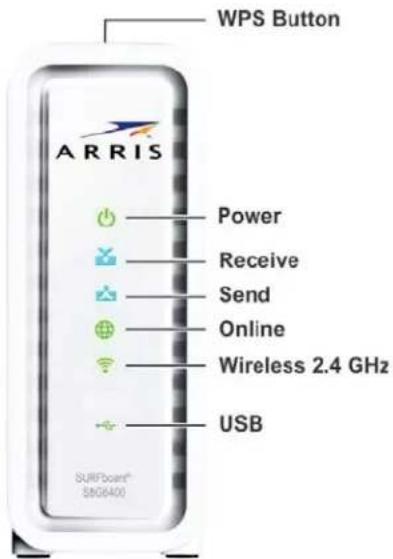
Figure 1 - SBG6400 Front View
Table 2: SBG6400 Front Panel LED Icons
| LED Icon | Blinking | On (Solid) |
 WPS Button WPS Button | Not applicable – no LED on buttonNote: The Wireless LED will blinkAmber to indicate the WPS pairing process is in progress. | Not applicable – no LED on button |
 POWER POWER | Not applicable – icon does not blink | Green: Power is properly connected |
 RECEIVE RECEIVE | Scanning for a downstream (receive) channel connection | Green: Non-bonded downstream channel is connectedBlue*: High-speed Internet connection with bonded downstream channels |
 | Scanning for an upstream (send) channel connection | Green: Non-bonded upstream channel is connectedBlue*: High-speed Internet connection with bonded upstream channels |
 | Scanning for an Internet connection | Green: Startup process completedNote: This may also indicate that your SBG6400 is connected to your service provider, but it may not be provisioned. |
 | Green: Wi-Fi enabled with encrypted wireless data activity.Amber: WPS Pairing process is underway between the SBG6400 and a WPS-enabled wireless device. | Green: Any of the following applies:2.4 GHz wireless connection is made between the SBG6400 and another Wi-Fi enabled device on your home network; for example, Wi-Fi telephone, tablet, or laptop.The WPS Pairing process between the SBG6400 and WPS-enabled wireless device was successful.The WPS Pairing process either failed or did not complete after two minutes. |
 | Green: Read/write activity is detected on the connected USB device. | Green: USB device is detected after it is connected to the SBG6400. |
*Indicates DOCSIS 3.0 operation (high-speed Internet access) which may not be available in all locations. Check with your service provider for availability in your area.
Wi-Fi Protected Setup™ (WPS)
Wi-Fi Protected Setup (WPS) is a wireless network setup option that provides a quick and easy solution for setting up a secure wireless network connection for any WPS-enabled wireless device; such as a computer, tablet, gaming device, or printer. WPS automatically configures your wireless network connections and sets up wireless security. See Use the SBG6400 WPS Pairing Button for more information.
Rear Panel
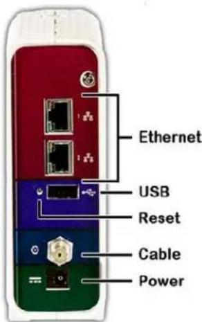
Figure 2 - SBG6400 Rear View
Table 3: SBG6400 Rear Panel Ports & Connectors
| Port Name | Description |
 | Two one-gigabit, 2.4 GHz only Ethernet ports for RJ-45 cable connections:Green - LED is ON - Indicates a device connection is detectedGreen - LED is Blinking - Indicates data traffic is in progressAmber - LED is ON - Indicates 10/100 Base-T connection(s)Amber - LED is OFF - Indicates GigE connection(s) |
 | USB 2.0 port connection to your USB device |
| Reset Button | Can be used to reboot the gateway or reset the gateway settings.To reboot (or restart) the gateway, press the indented Reset button once using the end of a paper clip or other small object with a narrow tip, and then release.To reset the gateway configuration back to the factory default settings, press and hold the indented Reset button for 15 seconds using the end of a paper clip or other small object with a narrow tip, and then release.See Reset Your Gateway Settings for more information on an alternative method to reset the gateway settings using the SBG6400 Web Manager. |
| Reset Button (continued) | WARNING! Resetting to factory defaults also deletes any custom gateway configurations, including your user passwords and other security settings. You should back up the gateway configuration files before resetting the gateway. See Back Up Your Gateway Configuration for more information. |
| CABLE | Coaxial cable connector |
| POWER | 12VDC Power line voltageWARNING! To avoid any damage to your SBG6400 Gateway, only use the power adapter and cord provided in the box. |
Gateway Label
The gateway label is located on the bottom of the SBG6400. It contains specific gateway ID information that you may need when contacting your service provider or call ARRIS Technical Support.
To receive Internet service, you may have to contact your service provider for assistance. You may need to provide the following information listed on the gateway label:
• Gateway model name (SBG6400)
• Gateway MAC address (HFC MAC ID)
• Gateway serial number (S/N)
3
Installing the Gateway

This product is for indoor use only. Do not route the Ethernet cable(s) outside of the building. Exposure of the cables to lightning could create a safety hazard and damage the product.
Connect the SBG6400 to Your Computer
Before installing the SBG6400:
- Check with your service provider to ensure broadband cable service is available in your area. To set up a wireless network, you will need a high-speed Internet connection provided by an Internet service provider.
Note When contacting your service provider, you may need your gateway information listed on the gateway label located on the bottom of the SBG6400 (see Gateway Label).
- Choose a location in your home where your computer and gateway are preferably near existing cable and electrical wall outlets.
For the best Wi-Fi coverage, a central location in your home or building is recommended.
Note The following installation procedure covers the wired Ethernet connection process so that you can confirm that the SBG6400 was properly installed and can connect to the Internet.
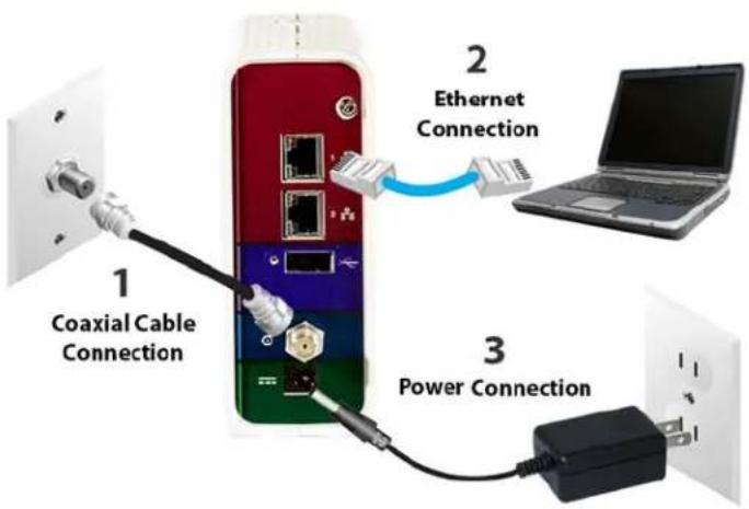
Figure 3 - SBG6400 Connection Diagram
- Check that a coaxial cable is already connected to a live cable wall outlet or RF splitter (optional).
- Connect the other end of the coaxial cable to the Cable connector on the SBG6400.
Use your hand to tighten the connectors to avoid damaging them. - Connect the Ethernet cable (included) to an available Ethernet port on the SBG6400.
- Connect the other end of the Ethernet cable to the Ethernet port on your computer or other network device in your home.
Optional: Repeat steps 3 and 4 for an additional computer or other network device that you want to install as a wired connection on your home network. - Connect the power cord (included) to the Power port on the SBG6400.
- Plug the other end of the power cord into an electrical wall outlet.
Note This automatically powers ON the SBG6400.
Establish an Internet Connection
Although your computer may already be configured to automatically access the Internet, you should still perform the following gateway connectivity test to verify that the devices were connected properly.
- Power ON the computer connected to the SBG6400, if it is turned off, and then log on.
- Contact your service provider to activate (provision) the SBG6400. You may have to provide the HFC MAC ID listed on the gateway label.
Note Your service provider may allow for automatic activation which will automatically launch its own special website when you open a web browser.
- After the SBG6400 is activated, open a web browser (Internet Explorer, Google Chrome, Firefox, or Safari) on your computer or other network device.
If the service provider's website did not open, continue with step 4. If it did open, proceed to step 5.
- Type a valid URL (such as www.surfboard.com) in the address bar and then press Enter.
The ARRIS website should open. If it did not open, do one of the following:
• See Troubleshooting Tips for more information.
- Contact your service provider for assistance.
- See Troubleshooting Tips for more information. - Contact your service provider for assistance.
Note: Do not attempt to change the network options on your computer to access the Internet.
Contact your service provider first.
- Check that the Power, Receive, Send, and Online front panel LEDs on the SBG6400 light up in sequential order (see Front Panel for additional LED status information).
- If all four LEDs did not light up solid and you also do not have an Internet connection, you may have to contact your service provider to reactivate the SBG6400 or check for possible signal issues.
• If you still cannot connect to the Internet, please call ARRIS Technical Support.
4
Setting Up a Wireless Network Connection
ARRIS recommends that you first verify that your computer can connect to the Internet using an Ethernet connection before configuring your wireless network.
You must already have Internet access in your home before setting up a wireless network connection. Also, make sure your computer and the SBG6400 are connected through an Ethernet connection.
Choose one of the following options to set up your wireless network connection:
- Launch the SBG6400 Quick Start Wizard
- Set Up a Wireless Network Using Your Computer
After setting up your wireless network connection, check that your wireless network connection was set up properly. See Test Your Wireless Network Connection for more information.
Launch the SBG6400 Quick Start Wizard
The SBG6400 Quick Start Wizard is a six-step application to help you quickly customize the default wireless network settings on your SBG6400. It configures your wireless network name (SSID), Wi-Fi Security key (network password), and Wi-Fi Security code.
IMPORTANT NOTE: The quick start wizard uses the default settings already configured for your SBG6400 to help you quickly set up your wireless home network. However, the wizard will only let you change the wireless network name (SSID) and Wi-Fi Security key (network password). After completing the wizard and getting your SBG6400 connected to the Internet, you will be able to make additional network configuration changes to further customize your wireless home network and connect your wireless devices. See Configuring Your Wireless Network for more information.
- Open a web browser (such as Internet Explorer, Google Chrome, Firefox, or Safari) on the computer connected to the SBG6400.
- Type the default LAN IP address, http://192.168.0.1, in the Address bar and then press Enter. The gateway Login screen displays (see Figure 4).
-
Type the default username and password. Both entries are case-sensitive.
-
Username: admin
- Password: password
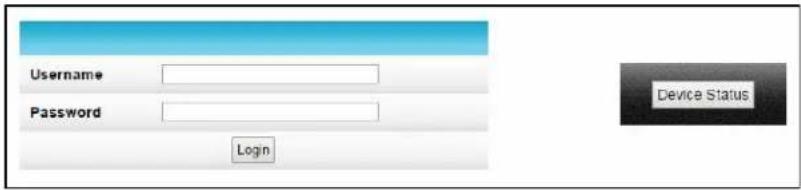
Figure 4 – Gateway Login Screen with Device Status Button
Note The Device Status button provides a quick method for you to view the current configuration settings and connection status of your SBG6400 without having to log in to the SBG6400 Web Manager (see View Your Gateway Status and Network Connection for more information).
- Click Login to open the SBG6400 Web Manager. The following Alerts screen displays.
Note If the default user name and password are not working, your service provider may have to set up alternate login credentials. Please contact your service provider or call ARRIS Technical Support for assistance.
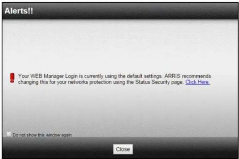
Figure 5 - Login Alerts Screen
The Login Alerts screen displays when you log in using the default username and password. ARRIS recommends changing the username and password for network security purposes. There are two options available:
• Quick Start Wizard (continue with step 5 in this procedure)
- SBG6400 Web Manager (see Change the Default Username and Password for more information)
For now, continue with the following steps to set up your wireless network connection.
- Click Close to close the Login Alerts screen. The Launch Quick Start Wizard screen displays.
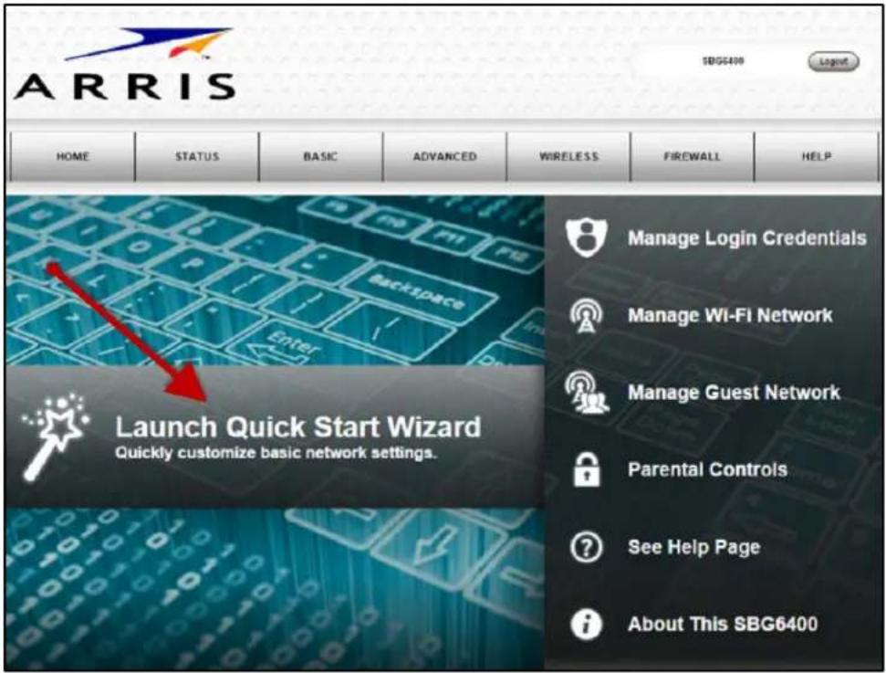
Figure 6 – SBG6400 Quick Start Wizard Opening Screen
- Click Launch Quick Start Wizard to start the wizard. The Welcome screen displays.
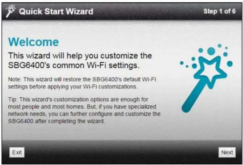
Figure 7 – SBG6400 Quick Start Wizard Welcome Screen
- Click Next to open the Wi-Fi Network Name & Passphrase screen.
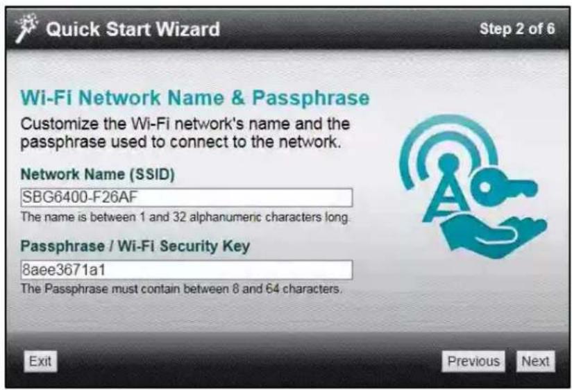
Figure 8 – SBG6400 Quick Start Wizard-Step 2 of 6 Screen
-
Do one of the following to change your wireless network name in the Network Name (SSID) field for connecting to your home network:
-
Keep the default network name or SSID (also listed on the SBG6400 gateway label).
Note You must keep the default network name, if this is your first time setting up your wireless network. You cannot change the network name until after you have completed the installation wizard. - Enter a name of your choice for your wireless network. Your new network name must contain from one to 32 alphanumeric characters.
Note: You can change your wireless network name (SSID) as many times as you wish after you have completed setting up your wireless network for the first time. You can also use the SBG6400 Web Manager to change your SSID (see Change Your Wireless Network Name (SSID) for more information).
-
Do one of the following to change your wireless network password in the Passphrase / Wi-Fi Security Key field:
-
Keep the default passphrase or Wi-Fi Security key (also listed on the SBG6400 gateway label).
- Enter a password of your choice for your wireless network password.
The passphrase or Wi-Fi Security key is the sign-on access code for your wireless network. The access code must contain from eight to 64 characters consisting of any combination of letters, numbers, and symbols. It should be as unique as possible to protect your wireless network and deter hackers or unauthorized access to your wireless network.
Note ARRIS recommends that you change the default Wi-Fi Security Key to a more secure wireless password to protect your wireless network from unauthorized access. See Prevent Unauthorized Access for more information.
- Click Next to open the Wi-Fi Security Configuration screen.
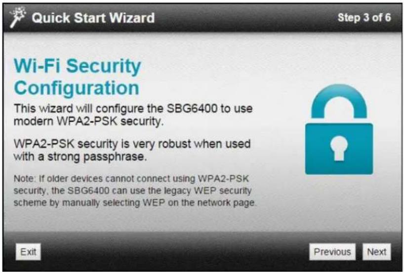
Figure 9 - SBG6400 Quick Start Wizard-Step 3 of 6 Screen
The wizard configures WPA2-PSK as the default wireless security code. It is the highest wireless network security level. See Set Up Your Wireless Primary Network to change the wireless security code for your wireless home network.
- Click Next to open the User Security Configuration screen (see Figure 10).
This screen allows you to change the current (or default) login username and user password to log on to the SBG6400 Web Manager.
a. Select Change Username checkbox and then enter your new username in both fields.
b. Select Change Password checkbox and then enter your new user password in both fields.
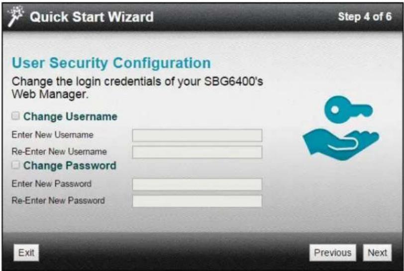
Figure 10 - SBG6400 Quick Start Wizard-Step 4 of 6 Screen
Note You must select each checkbox to activate the field to enter your new username and password. Otherwise, the fields are disabled. The Next button is disabled, if the username or password was not entered correctly. Make sure to repeat the same username and password in their respective fields.
- Click Next to open the Review Settings screen and confirm your wireless network settings.
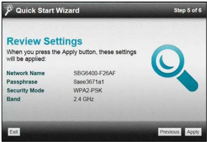
Figure 11 - SBG6400 Quick Start Wizard-Step 5 of 6 Screen
- Click Apply to accept the wireless network settings and open the Settings Applied screen or click Previous to go back and change your wireless network name and/or user password. Wait for your wireless network settings to be saved. When it is complete, the Settings Applied screen will open.
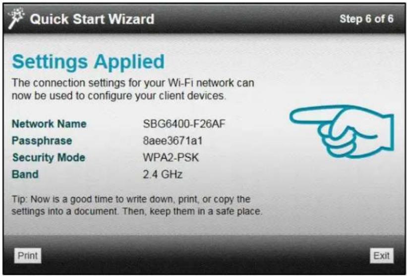
Figure 12 - SBG6400 Quick Start Wizard-Step 6 of 6 Screen
- Click Exit on the Settings Applied screen to close the SBG6400 Quick Start Wizard.
Note: You can click Print to print a copy of your wireless network settings from a connected printer. This can handy for keeping a record of your new wireless network settings.
Set Up a Wireless Network Using Your Computer
Use one of the following options to create your wireless network:
• Quick Connect Using the Windows Taskbar
- Connect Using the Windows Control Panel
Note The steps for setting up a wireless network may differ slightly depending on the Windows operating system running on your computer. The steps used here apply to Windows 7.
Quick Connect Using the Windows Taskbar
- From the Windows taskbar (see Figure 13), click the Wireless Link icon to open the list of available wireless networks (see Figure 14).
Note If the icon is not visible, click the Show hidden icons button (see below) on the Windows taskbar to open and select from the list of additional icons.

Figure 13 – Windows Taskbar Icons
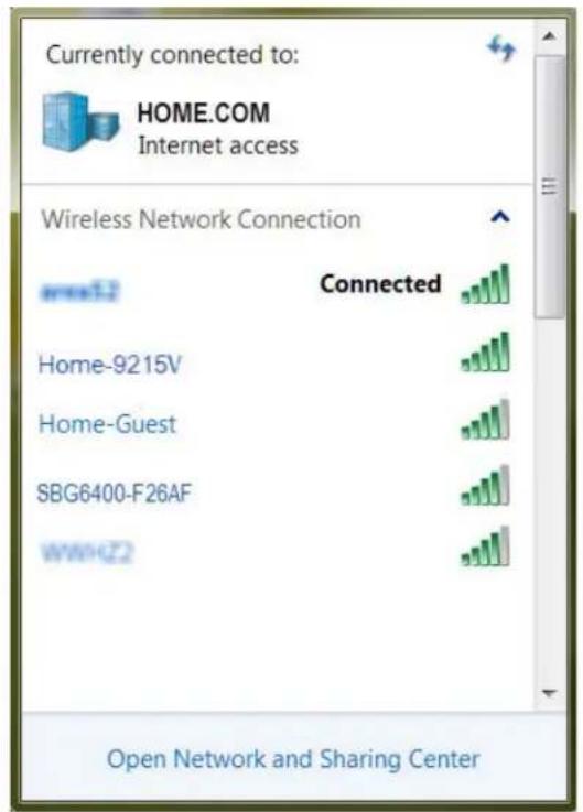
Figure 14 – Sample Available Wireless Networks Window
- Locate and then left-click on the SBG6400 wireless network name or SSID (for example, SBG6400-#####) for your SBG6400 from the wireless networks list (see Figure 15).
The default SSID is listed on the gateway label on the bottom of your SBG6400.
Note You must use the default wireless network name or SSID listed on the gateway label to set up your wireless network connection for the first time. However, you have the option to change your wireless network name (SSID) later after you have completed your wireless network connection here. See Change Your Wireless Network Name (SSID) for more information.
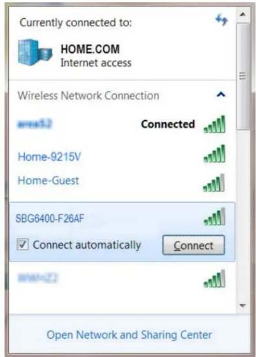
Figure 15 – Sample Available Wireless Networks Window
- Select Connect automatically to set up your wireless devices for automatic connections to your home network upon log on.
- Click Connect to open the Connect to a Network window.
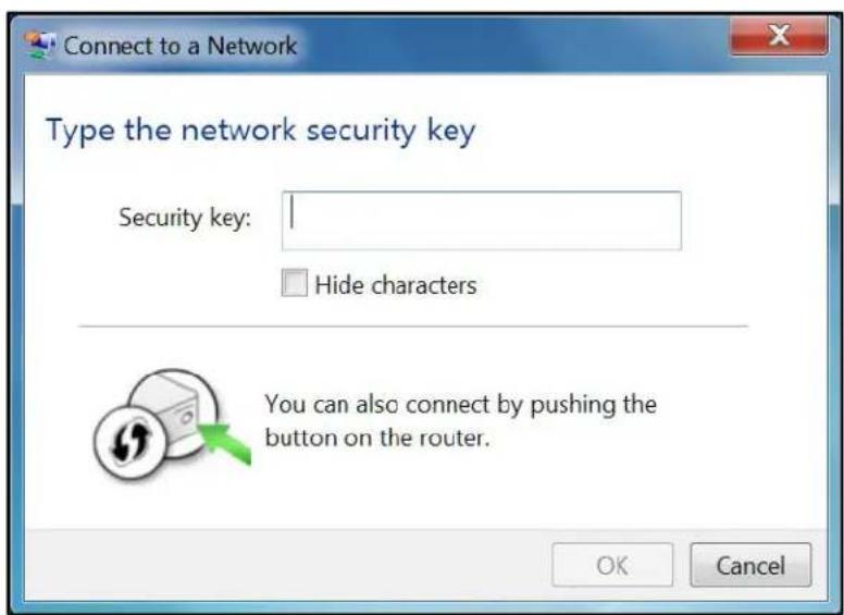
Figure 16 – Network Connection Window
- Enter the default Wi-Fi Security Key code for your wireless network password in the Security key field (check your SBG6400 gateway label).
Note: If you have already changed your wireless network password using the SBG6400 Web Manager, enter that password in the Security key field.
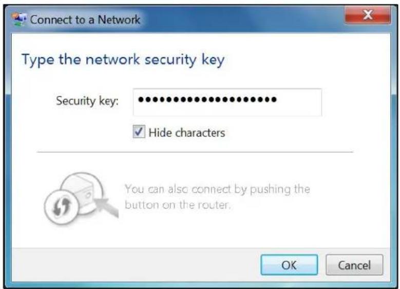
Figure 17 – Network Connection-Create Network Password Window
- Select Hide characters and then click OK to encrypt (or hide) your network Security key (network password).
Connect Using the Windows Control Panel
- From the Windows taskbar, click Start button and then click Control Panel.
- Click Network and Sharing Center to open the Network and Sharing Center window.
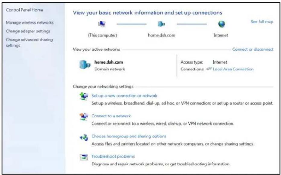
Figure 18 - Control Panel-Network and Sharing Center Window
- Click Manage wireless networks under Control Panel Home (left side of the window) to open the list of available networks.
- Click Add on the network list menu bar to open the Manually connect to a wireless network window.
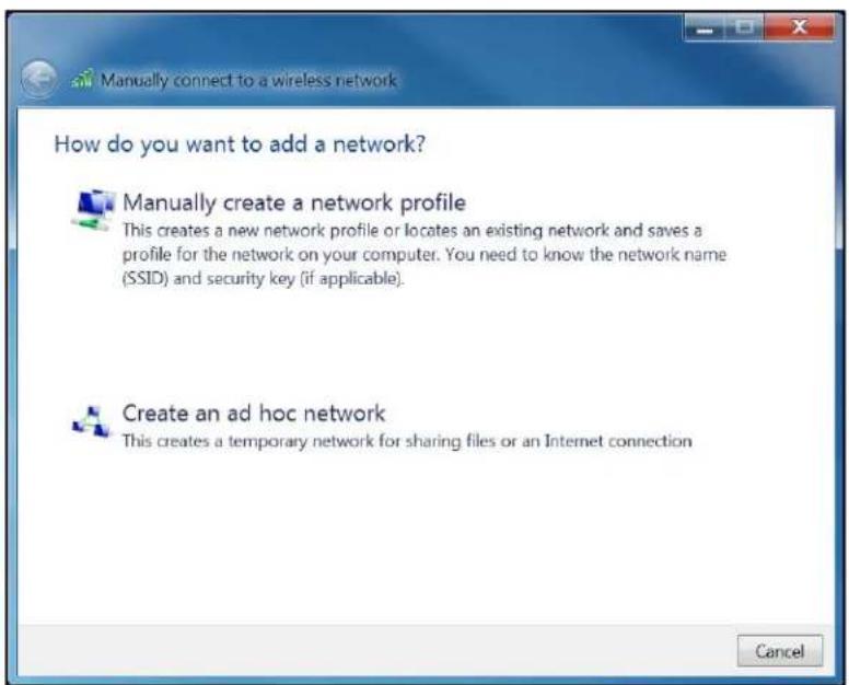
Figure 19 – Manually Connect to a Wireless Network Window
- Click Manually create a network profile to open another Manually connect to a wireless network window.
![Manually connect to a wireless network Enter information for the wireless network you want to add Network name: Security type: [Choose an option] Encryption type: Security Key: Hide characters Start this connection automatically Connect even if the network is not broadcasting Warning: If you select this option, your computer's privacy might be at risk.](/content/2026/05/1042078/images/7e2ad776fe44bc71639bd755f4301399d5a02d7515bcbf8eb7ec403e60160080.jpg)
Figure 20 – Manually Connect to a Wireless Network Window
-
Enter the ARRIS wireless network name or SSID (SBG6400-######) for your SBG6400 in the Network name field. Do one of the following:
-
Enter the default SSID name listed on the gateway label on the bottom of your SBG6400.
• If you have already changed the wireless network name, enter it here.
Note You have the option to change your wireless network name (or SSID) after setting up your wireless network connection for the first time. See Change Your Wireless Network Name (SSID) for more information.
- Select the wireless Security level for your wireless network from the Security type drop-down list.
Note ARRIS recommends the WPA2-Personal wireless security level. It is the highest security level available and also the default security level for the SBG6400.
- Select the password encryption type from the Encryption type drop-down list. This is used for network security.
• TKIP – Temporal Key Integrity Protocol
- AES – Advanced Encryption Standard (recommended). AES is the default encryption type for the SBG6400.
- Enter a Security code or passphrase for your wireless network password in the Security Key field.
You can use the WI-FI Security Key listed on the SBG6400 gateway label or create your own personal network password.
Note Remember to use a unique combination of letters, numbers, and characters to create a more secure password. See Prevent Unauthorized Access for more information.
- Select Hide characters to prevent your Security Key or password from displaying in the field.
- Select Start this connection automatically so that your wireless devices will automatically connect to your wireless network when they are logged on.
- Click Next to complete the wireless network setup.
The Successfully addedmessage for your new wireless network should appear. - Click Close to exit.
Test Your Wireless Network Connection
Perform the following connectivity test to check that the SBG6400 and other wireless devices are connected to your wireless home network:
- Disconnect the Ethernet cable from your computer and the SBG6400, if your wireless devices successfully connected to your wireless network.
- Open a web browser on your computer.
- Type a valid URL (such as www.surfboard.com) in the address bar, and then press Enter. If the website did not open, please contact your service provider or call ARRIS Technical Support for assistance.
Use the SBG6400 WPS Pairing Button
The WPS Pairing button automatically connects your WPS-enabled wireless devices to your wireless home network using the default SBG6400 SSID (network name) and Wi-Fi Security Key (network password) listed on the gateway label.
Note: To use the WPS Pairing button option, your computer hardware must support WPS and also have WPA security compatibility.
- Power ON your gateway and other WPS-enabled wireless devices that you want to connect to your wireless network.
- Press and hold the WPS button located on the top of the SBG6400 for five to 10 seconds and then release (see Front Panel for the SBG6400 front view).
- If applicable, press the WPS button on your WPS-enabled computer or other WPS device.
- Repeat step 3 for each additional WPS-enabled wireless device that you want to connect to your wireless network.
5
Using the Gateway Web Manager
Use the SBG6400 Web Manager to view and monitor the configuration settings and operational status of your gateway. You can also configure your network connections and wireless security settings. See Protecting & Monitoring Your Wireless Network for more information.
Note If you did not purchase your gateway from a retail store, you may notice a few blocked configuration settings in the SBG6400 Web Manager that cannot be modified. This may be due to some restrictions set up by your service provider to prevent unauthorized changes to certain configuration parameters.
Start the Gateway Web Manager
- Open any web browser on the computer connected to the SBG6400.
- In the Address bar, type 192.168.0.1 for the Gateway Web Manager IP address, and then press Enter. The gateway Login screen displays.

Figure 21 - Gateway Login Screen
Note You must use the default user name and password (listed below) to login to the SBG6400 Web Manager for the first time.
-
Type the default user name and password. Both entries are case-sensitive.
-
Username: admin
-
Password: password
-
Click Login to open the SBG6400 Web Manager. The SBG6400 Web Manager Main Screen displays (see Figure 22).
-
If the default user name and password are not working, your service provider may have to set up alternate login credentials. Please contact your service provider or callARRIS Technical Support for assistance.
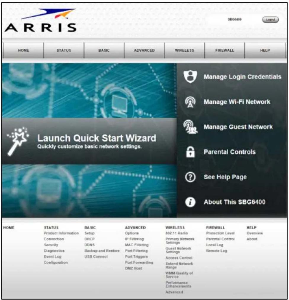
Figure 22 - SBG6400 Web Manager Main Screen
Note The Login Alerts screen below will display if you logged in using the default username and password. ARRIS recommends changing your username and password for network security purposes. See Change the Default Username and Password for more information.
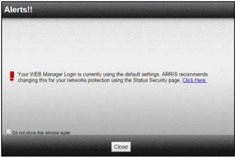
Figure 23 - Login Alerts Screen
Gateway Web Manager Menu Options
Main Menu Buttons
The SBG6400 main menu buttons are displayed along the top of the SBG6400 Web Manager screen. To display the drop-down submenu options, click the menu button.
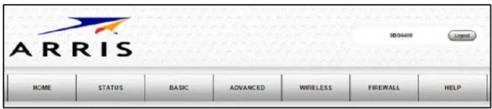
Figure 24 - SBG6400 Web Manager Main Menu Buttons
Main Menu Links
The SBG6400 main menu and related submenu option links are also displayed along the bottom of the SBG6400 Web Manager screen. To open a submenu option, click on the link.
| HOME | STATUS | BASIC | ADVANCED | WIRELESS | FIREWALL | HELP |
| Product Information | Setup | Options | 802.11 Radio | Protection Level | Overview | |
| Connection | DHCP | IP Filtering | Primary Network Settings | Parental Control | About | |
| Security | DONS | MAC Filtering | Gurat Network Settings | Local Log | ||
| Diagnostics | Backup and Restore | Port Filtering | Remote Log | |||
| Event Log | USB Connect | Port Triggers | Access Control | |||
| Configuration | Port Forwarding DMZ Host | Extend Network Range | ||||
| WMM Quality of Service | ||||||
| Performance Enhancements | ||||||
| Advanced |
Figure 25 - SBG6400 Web Manager Main Menu Links
Table 4: SBG6400 Web Manager Main Menu Options
| Menu Option | Function |
| Home | Displays the Quick Start Wizard main screen. |
| Status | Provides information about the gateway hardware and software, MAC address, gateway IP address, serial number, and related information.Additional screens provide diagnostic tools and also allow you to change your gateway user name and password. |
| Basic | Configures the gateway IP-related configuration data, including Network Configuration, WAN Connection Type, DHCP, and DDNS. |
| Advanced | Controls Internet protocols which configure and monitor how the gateway routes IP traffic on the SBG6400. |
| Wireless | Configures and monitors the gateway wireless networking features. |
| Firewall | Configures and monitors the gateway firewall. |
| Help | Provides general information to help you set up your home network. |
Get Help
You can choose any of the following three options to obtain help information for any SBG6400 Web Manager function. General help information is available for any SBG6400 menu option when you click the Help button on that page.
- Overview Help
- Help Links
- Field Level Help
Overview Help
General help information is available when you click Help, Overview on the SBG6400 Main Menu.
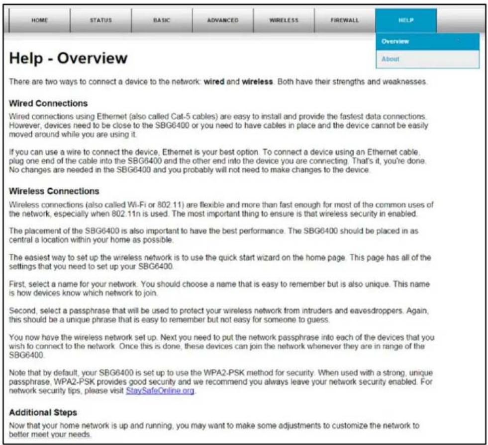
Figure 26 – Help Overview Screen
Help Links
Provides a concise list of your gateway configuration settings with applicable links for easy access when you click Help, About on the SBG6400 Main Menu. The link opens the related configuration screen.
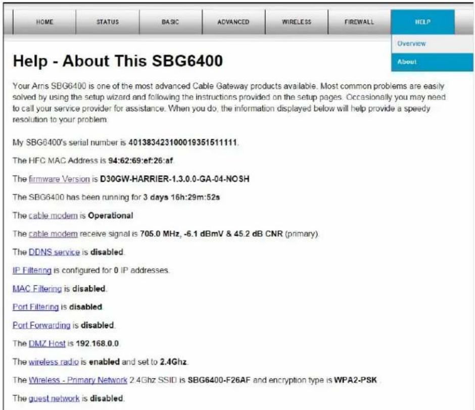
Figure 27 - Help Links Screen
Field Level Help
More specific help information is available throughout the web manager for field level help when you click the Help link located to the right of the applicable field.
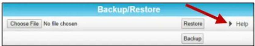
Figure 28 – Field Level Help Screen
Exit the SBG6400 Web Manager
To log out and close the SBG6400 Web Manager:
- Click Logout located in the upper right corner of the screen above the SBG6400 Main Menu buttons.
6
Configuring Your Wireless Network
The SBG6400 supports a secure method for setting up multiple access points on your wireless home network. This enables you to designate a guest network for visitors, friends, or other family members without giving them access to your files or other devices on your primary network. You have the option to create a PIN or pushbutton method for logging onto your wireless network.
Set Up Your Wireless Primary Network
- Open a web browser and log onto the SBG6400 to open the SBG6400 Web Manager. See Start the Gateway Web Manager for more information.
- Click Wireless on the SBG6400 Main Menu bar.
- Click Primary Network Settings from the Wireless submenu options.
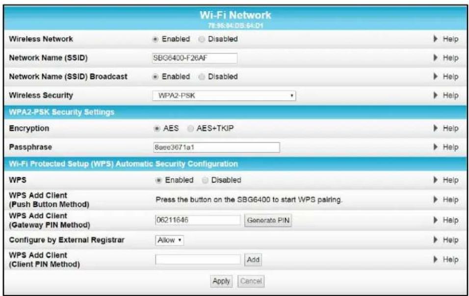
Figure 29 – Wireless Primary Network Settings Screen
- Select Enabled or Disabled in the Wireless Network field to turn ON or OFF wireless networking on your wireless network.
- Keep the default network name (also listed on the gateway label) or enter a name of your choice for your wireless primary network in the Network Name (SSID) field.
The network name must consist of any combination of up to 32 ASCII characters. It cannot match any other SSID on your SBG6400.
- Select Enabled or Disabled in the Network Name (SSID) Broadcast field to turn ON or OFF outside access to your wireless network.
- Select one of the following wireless network security options for your wireless network from the Wireless Security drop-down list:
• WPA2-PSK: Wi-Fi Protected Access version 2 with Pre-Shared Key (recommended)
- WPA2-PSK + WPA-PSK: combination Wi-Fi Protected Access version 2 with Pre-Shared Key and Wi-Fi Protected Access with Pre-Shared Key
• Unencrypted: Allows access to the wireless network without a Wi-Fi Security Key
• WPA-PSK: Wi-Fi Protected Access with Pre-Shared Key, standard encryption
- WPA2 (Enterprise): Wi-Fi Protected Access version 2 provides additional network security and requires a user name and password for network logon
- WPA2 + WPA (Enterprise): combination Wi-Fi Protected Access version 2 and Wi-Fi Protected Access provides additional network security and requires a user name and password for network logon
-
Choose the wireless network encryption type in the Encryption field:
-
AES – Advanced Encryption Standard: Provides the strongest encryption (recommended)
-
AES+TKIP – Advanced Encryption Standard and Temporal Key Integrity Protocol Allows both AES and TKIP-capable clients to connect to your wireless network
-
Enter any combination of characters and words for your network password in the Passphrase field.
-
Click Apply if you are done or continue with Enable or Disable WPS on Your Wireless Network below to set up WPS on your wireless network.
Enable or Disable WPS on Your Wireless Network
From the Wireless Primary Network screen, go to the WPS Automatic Security Configuration section:
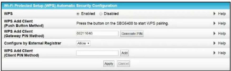
Figure 30 - WPS Setup Screen
- Select Enabled in the WPS field to turn ON the Wi-Fi Protected Setup (WPS) network security on your home network. Continue with step 2.
- or -
Select Disabled in the WPS field to turn OFF the Wi-Fi Protected Setup (WPS) network security on your home network. Proceed to step 3 to finish.
- Select one of the following WPS Pairing methods to add or pair your WPS-enabled wireless devices:
- Push Button – Press the WPS button on the SBG6400 to start the WPS pairing process with the WPS-enabled wireless device you want to connect to your wireless network.
Repeat for each additional WPS-enabled wireless device.
- Gateway PIN – Click Generate PIN to automatically create a new numeric password for logging onto your wireless home network.
- Configure by External Registrar – Select to Allow or Deny the client to enter the PIN to access a wireless access point on your wireless network.
Note: This feature is not recommended.
- Client PIN – Enter a numeric password to log onto your wireless network and then click Add.
- Click Apply.
Set Up a Wireless Guest Network
Note: This feature may be disabled on your SBG6400. Some service providers or cable operators do not allow for secondary (or guest) wireless networks on their gateway devices.
- Open a web browser and log onto the SBG6400 to open the SBG6400 Web Manager. See Start the Gateway Web Manager for more information.
- Click Wireless on the SBG6400 Main Menu bar.
- Click Guest Network Settings on the Wireless submenu options (see Figure 31).
- Select the guest network from the Selected Guest Network drop-down list.
- Select Enabled or Disabled in the Guest Network field to turn ON or OFF the selected wireless guest network.
- Do one of the following to name your wireless guest network in the Guest Network Name (SSID) field:
- Keep the default guest network name.
- Enter a new name of your choice.
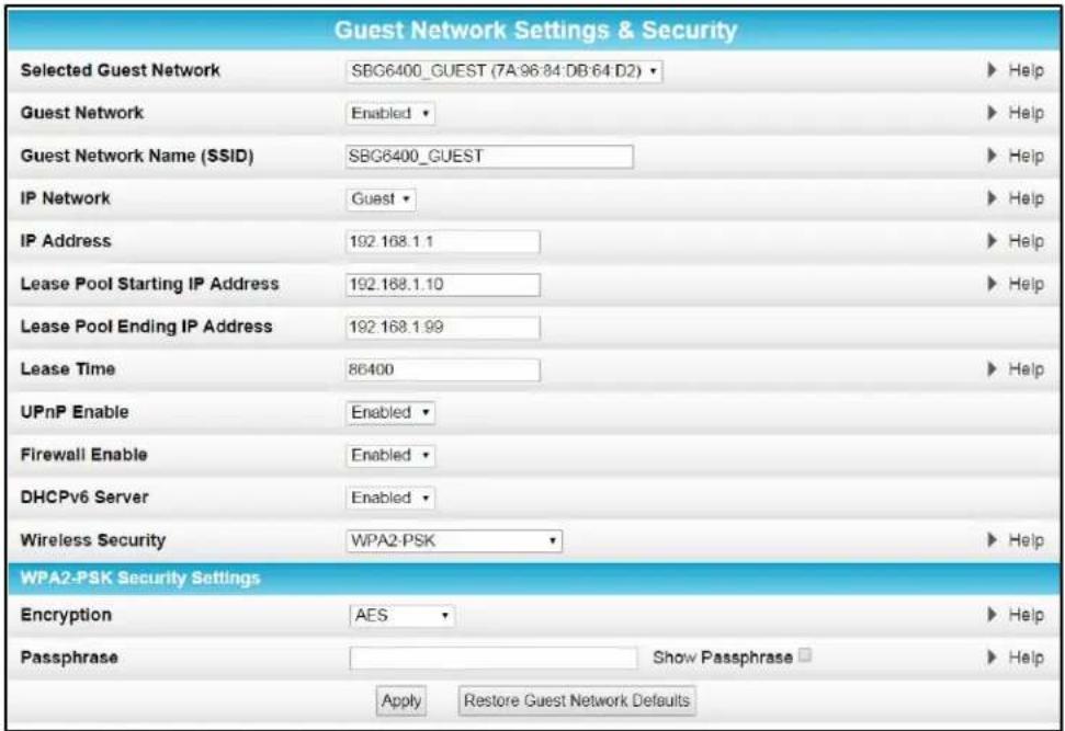
Figure 31 – Wireless Guest Network Screen
-
Select LAN or Guest from the IP Network drop-down list.
-
LAN – Configures the guest network to be part of your primary network and allow guest users to connect to your primary network
-
Guest – Configures the guest network to only allow access to a specific network and not your primary network
-
Enter the IP address for the SBG6400 on the Guest network in the IP Address field.
- Enter the starting IP address for the guest network lease pool in the Lease Pool Starting IP Address field.
- Enter the ending IP address for the guest network lease pool in the Lease Pool Ending IP Address field.
- Enter the lease time for the guest network lease pool in the Lease Time field.
- Select Enabled or Disabled in the UPnP (Universal Plug and Play) Enable field to allow or disallow any network devices, such as smart phones, tablets, gaming devices, or printers to automatically connect to your wireless home network.
- Select Enabled or Disabled in the Firewall Enable field to turn ON or OFF the gateway firewall.
-
Select Enabled or Disabled in the DHCPv6 Server field to allow the DHCPv6 server to send leases to the guest network clients from the guest network lease pool you specified earlier. Note If the DHCP server is disabled, you must assign static IP addresses to the guest network STAs.
-
Select one of the following wireless network security options for your guest network from the Wireless Security drop-down list:
• WPA2-PSK: Wi-Fi Protected Access version 2 with Pre-Shared Key (recommended)
- WPA2-PSK + WPA-PSK: combination Wi-Fi Protected Access version 2 with Pre-Shared Key and Wi-Fi Protected Access with Pre-Shared Key
• WPA-PSK: Wi-Fi Protected Access with Pre-Shared Key, standard encryption
• Unencrypted: Turns off network security
- WPA2 + WPA (Enterprise): combination Wi-Fi Protected Access version 2 and Wi-Fi Protected Access provides additional network security and requires a user name and password for network logon
- WPA2 (Enterprise): Wi-Fi Protected Access version 2 provides additional network security and requires a user name and password for network logon
Note Additional network security settings based on the wireless network security option you select will display.
- Click Apply.
Change Your Wireless Network Name (SSID)
The SSID (Service Set Identification) is the wireless network name assigned to your SBG6400 wireless primary and guest networks. The default SSID which is listed on the gateway label is automatically populated in the network configuration screens. A list of SSIDs of available wireless networks in close proximity of your home (for example, neighbors or local businesses) will display when you or someone else in your home attempt to establish a wireless network connection. For security purposes and quick recognition of your wireless network, ARRIS recommends that you change the default SSID. You should also consider changing the default wireless password or passphrase (see Prevent Unauthorized Access for more information).
Note When you change the SSID, any wireless devices that are already connected to your wireless network will be disconnected from the network. The wireless devices will have to be reconnected to the wireless network using the new SSID.
Do the following to change your wireless network name or SSID:
-
Open a web browser and log onto the SBG6400 to open the SBG6400 Web Manager. See Start the Gateway Web Manager for more information.
-
Click Wireless on the SBG6400 Main Menu bar.
-
Click Primary Network Settings from the Wireless submenu options to open the Wi-Fi Network screen.
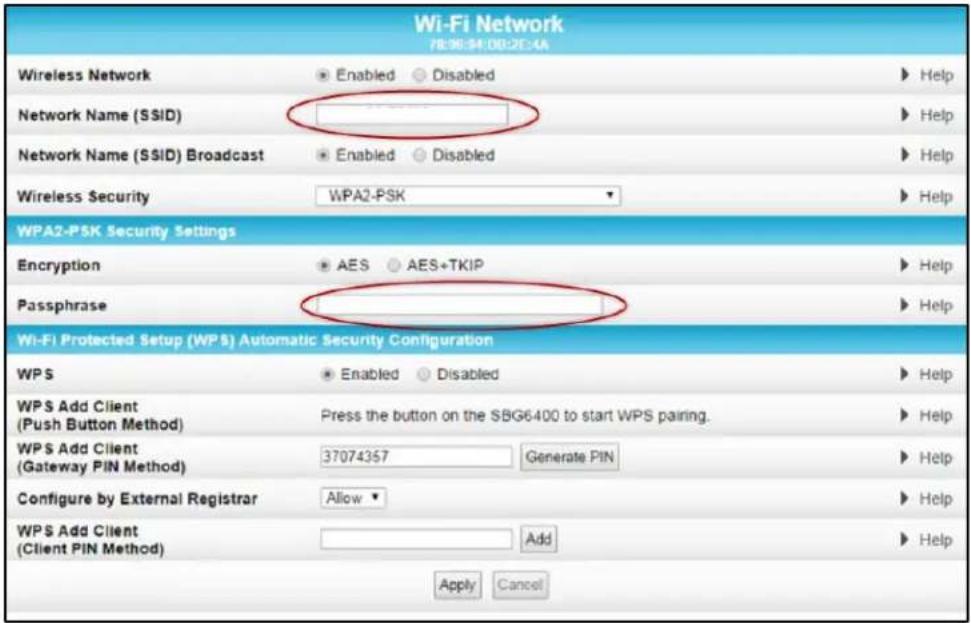
Figure 32 – Change Your Network Name (SSID) and Password Screens
- Make sure Enabled is selected in the Wireless Network field to turn ON wireless networking on your home network.
- Delete the current network name in the Network Name (SSID) field and then enter a new name of your choice for your wireless network.
- The network name can contain any combination of up to 32 alphanumeric characters.
- Make sure Enabled is selected in the Network Name (SSID) Broadcast field.
- Delete the current wireless password (passphrase) in the Passphrase field and enter a new passphrase for the wireless network password.
- See Prevent Unauthorized Access for more information.
- Click Apply at the bottom of the screen.
The new wireless network name should appear in the list of available wireless networks when you reconnect your wireless devices.
Change the Wireless Channel
Network interference may occur at any time when using a wireless network connection. This may be caused by other wireless access points that are using the same wireless channel as your SBG6400 and are also operating within close proximity in your home. When experiencing wireless network interference, changing the wireless channel on the SBG6400 can improve network connectivity (or signal strength) and avoid network interference. By default, the SBG6400 is set on Channel 1.
Do the following to change the wireless channel on the SBG6400:
- Open a web browser and log onto the SBG6400 to open the SBG6400 Web Manager. See Start the Gateway Web Manager for more information.
- Click Wireless on the SBG6400 Main Menu bar.
- Click 802.11 Radio from the Wireless submenu options to open the Wireless 802.11 Radio screen.
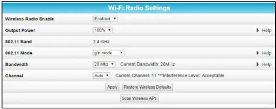
Figure 33 – Wireless 802.11 Radio Screens
- Select a channel number from the Channel drop-down list that is different from the channel number listed as the Current Channel.
Note ARRIS recommends to use Channel 6 or 11, if it is not listed as the Current Channel. In the Wi-Fi spectrum, there are multiple channels that overlap and thus degrade wireless network performance. Channels 1, 6, and 11 are used for better network performance and stability because they do not overlap.
- Click Apply.
7
Protecting & Monitoring Your Wireless Network
After you have successfully connected the SBG6400 and your wireless devices, you should configure the gateway to protect your wireless network from unwanted and unauthorized access by any wireless devices within range of your wireless network. Although security for the SBG6400 is already configured, you can use the SBG6400 Configuration Manager to tailor the level of security and access that you want to allow on your network.
Prevent Unauthorized Access

To prevent unauthorized access and configuration to your wireless network, ARRIS recommends that you immediately change the default user name and password after connecting to the Internet and logging on to the SBG6400 for the first time.
One of the most important recommendations for securing your wireless home network is to change the default administrator password on your SBG6400 and other wireless devices as well. Default passwords are commonly used and shared on the Internet.
To ensure that your wireless home network is secure, you should follow these best practices for creating user passwords:
• Always create a secure password or pass phrase that is not easily guessed.
- Use phrases instead of names so that it may be easier for you to remember.
- Use a combination of upper and lowercase letters, numbers, and symbols.
- Continue to change your administrator password on a regular basis.
Note If your service provider supplied the SBG6400, you may not have the necessary user privileges to change the login user name.
Change the Default Username and Password
To change the default username:
- Log in to the SBG6400 from any web browser on the computer connected to the SBG6400.
-
Type the Gateway Web Manager IP address, http://192.168.0.1, in the Address bar and then press Enter. The gateway Login screen displays.
-
Type the default username and password as they appear below:
-
Username: admin
-
Password: password
-
Click Login to open the SBG6400 Web Manager.
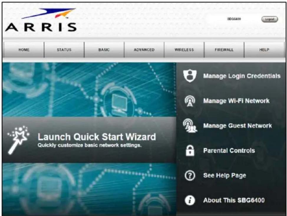
Figure 34 - SBG6400 Web Manager Main Screen
- Click the Status button on the menu bar and then click Security to display the Status Security screen.
- Confirm that Change Username is displayed in the drop-down selection box (see Figure 35).
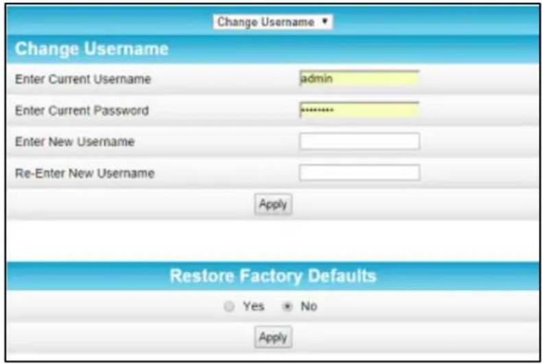
Figure 35 – Change Username Screen
- Complete each field entry, but note the following:
• All fields (for example, Current Username & Current Password) are case-sensitive.
Note: For first time logons, the current username is admin and the current password is password.
• Make sure No is selected under Restore Factory Defaults.
- Click Apply to update your user name.
- Click Change Username drop-down arrow to display Change Password.
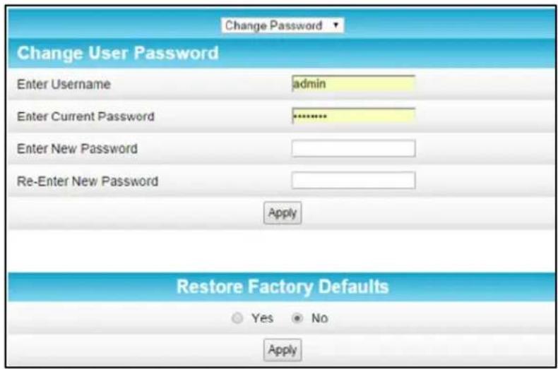
Figure 36 – Change User Password Screen
- Complete each field entry, but note the following:
• All fields are case-sensitive.
- Username is your new user name, if you changed it.
• Make sure No is selected for Restore Factory Defaults.
• Find a secure place to write down and keep your new user name and password.
- Click Apply to update your password.
Set Up Firewall Protection
You can set up firewall filters and firewall alert notifications on your wireless home network. You can also block Java Applets, Cookies, ActiveX controls, popup windows, Proxies, and website access. See Protection Level for more information.
To set the firewall protection level:
-
From any screen, do one of the following to open the Firewall Protection Level screen (see Figure 37):
-
Click the Firewall menu button on the SBG6400 Main Menu and then select Protection Level.
-
Click the Firewall-Protection Level menu link at the bottom of the screen.
-
Click the Firewall Protection Setting drop-down button to select the firewall protection level.
Possible values:
• Off - No security, highest risk
• Low - Common security, higher risk
• Medium - Safer configuration, modest risk
• High - Safest configuration, highest security
Note Selecting Off will disable firewall protection on your home network. Your computer(s) and other Ethernet-enabled devices on your network will be at risk for possible attacks from viruses and hackers.
-
Select each Web filter that you want to set for the firewall.
-
Click Apply.
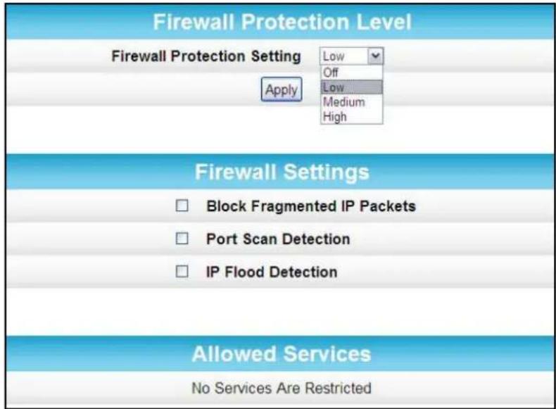
Figure 37 – Firewall Protection Level Screen
Set Up Firewall Event Log Notifications
When a firewall attack is detected on your home network, a separate email alert notification is generated and a local log or report of the event is created. You can set up automatic email alert notifications for whenever a firewall attack is detected on the SBG6400. See Local Log for more information.
To set up Firewall Event Log notifications:
- Click the Firewall-Local Log menu link or click the Firewall menu button on the SBG6400 Main Menu and then select Local Log.
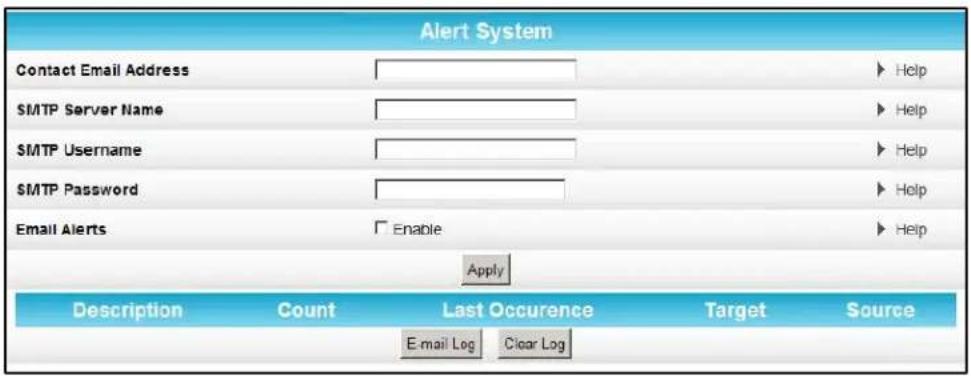
Figure 38 – Set Up Firewall Local Log Screen
-
Enter your email address in the Contact Email Address field.
-
Enter the name of the email server in the SMTP Server Name field. Check with your service or email provider.
- Enter the user name for your email account.
- Enter the password for your email account.
- Select Enable checkbox in the E-mail Alerts field to allow for automatic Email alerts.
- Click Apply.
Set Up Parental Controls
You can set up the following Parental Controls on your home network:
- Allow or block access to specific Internet sites.
- Allow or block access to specific MAC addresses.
- Set time limitations for computer usage or Internet access
Note. Any Parental Control filters that do not include assigned ports, will apply to all ports. This also applies to MAC addresses as well.
You can also link each user on your network to specified rules for login, time-access, and content filtering. See Parental Control for more information.
To set Parental Controls:
- From any screen, click the Firewall-Parental Control menu link or click the Firewall menu button on the SBG6400 Main Menu and then select Parental Control.
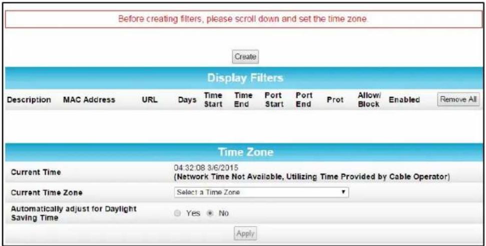
Figure 39 – Parental Control-Change Time Zone Screen
Note: Before setting up any Parental Control filters, you must first set the time zone on your SBG6400 for your current location.
- Click Current Time Zone drop-down button to select your time zone location.
- Select Yes or No to automatically adjust the time on your SBG6400 for Daylight Saving Time.
- Click Apply and then click Create to continue setting up Parental Controls.
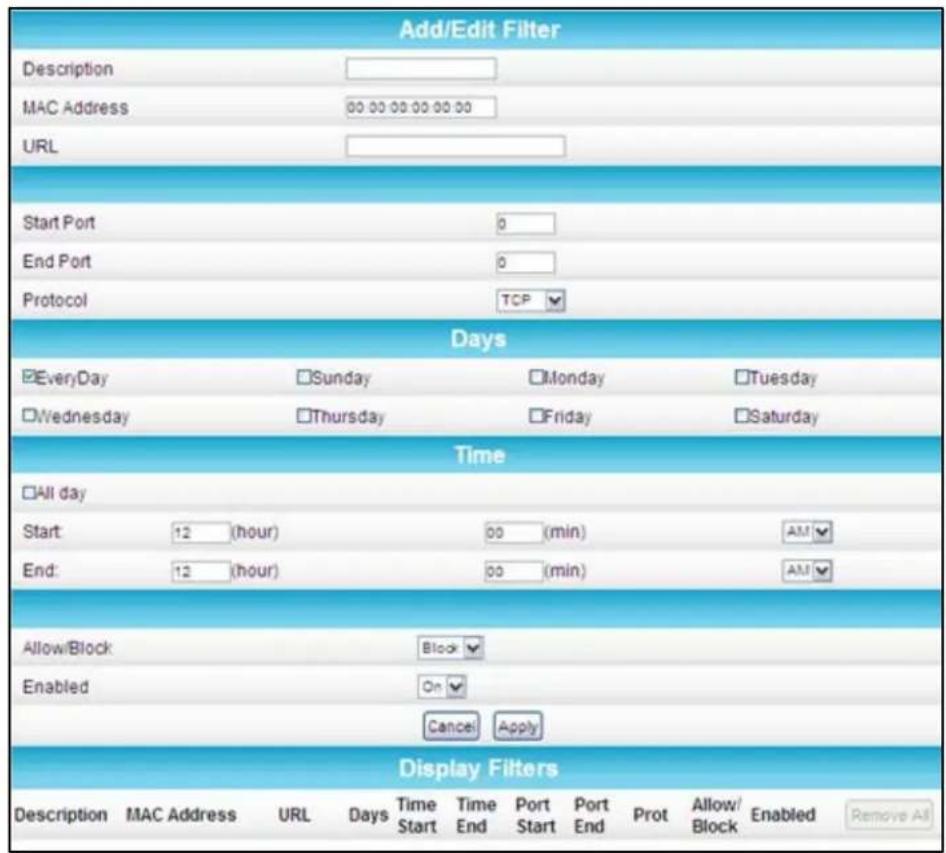
Figure 40 - Firewall Parental Control Screen
- Enter a name for the user profile that you want to create in the Description field.
- Enter the 12-digit (hexadecimal) MAC address of the device for which you are creating Parental Controls in the MAC Address field.
- Enter the web address of the Internet site that you want to block or access.
- Enter the Starting port number of the in the Start Port field.
- Enter the Ending port number of the in the End Port field.
- Select TCP, UDP, or BOTH from the Internet Protocol drop-down list.
- Select the days of the week that you want to allow the selected user to access the Internet.
- Select the time range that you want to allow the selected user to access the Internet.
- Select to Allow or Block Internet access for the time and days you set previously.
- Select On or Off in the Enabled field to enable or disable this Parental Control restriction.
- Click Apply, when done.
Set Up Port Triggers
You can use Port Triggers to configure dynamic triggers to specific devices on the LAN. This allows special applications that require specific port numbers with bi-directional traffic to function properly. Applications such as video conferencing, voice, gaming, and some messaging program features may require these special settings.
Note If you enable the firewall and set up custom port triggers, then you must set the firewall protection level to Low or Off to allow traffic through the custom ports. See Set Up Firewall Protection for more information.
To configure Port Triggers:
- Click Advanced on the SBG6400 Main Menu bar.
- Click Port Triggers from the Advanced submenu options.
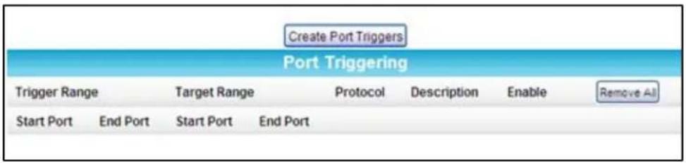
Figure 41 – Create Port Triggers Screen
- Click Create Port Triggers button to open the Add Port Triggering Entry window.
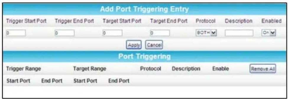
Figure 42 - Add Port Triggers Screen
- Enter the starting port number for the port to be triggered in the Trigger Start Port field.
- Enter the ending port number for the port to be triggered in the Trigger End Port field.
- Enter the starting port number of the Port Trigger range in the Target Start Port field.
- Enter the ending port number of the Port Trigger range in the Target End Port field.
-
Select TCP, UDP, or BOTH from the Internet Protocol drop-down list.
-
Enter a unique name in the Description field.
- Select On to enable IP port triggers or Off to disable them.
- Click Apply to create your port triggers.
- Repeat steps 3 thru 11 for each additional port trigger that you want to create.
Set Up Port Forwarding
You can use Port Forwarding to set up a computer or other network device on your home network (LAN) to be accessible to computers or other remote network devices on the Internet. This allows you to open specific ports behind the firewall on your LAN to set up dedicated connections between your computer and other remote computers for online gaming or other online services. Some allowable services are predefined under the Commonly Forwarded Ports. See Figure 45 for a list of commonly used port numbers.
Note ARRIS recommends that you manually configure the TCP/IP settings listed below on the computer you are setting up for remote access. Otherwise, remote access to your computer will not be available on the Internet.
- IP address
- Subnet mask
- Default gateway
• DNS address (at least one)
To set up Port Forwarding:
- Click Advanced on the SBG6400 Main Menu bar.
- Click Port Forwarding from the Advanced submenu options.
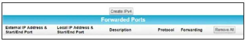
Figure 43 – Create Forwarded Ports Screen
- Click Create IPv4 to set up a specific port or range of ports for port forwarding.
Note To map a port, you would enter the range of port numbers that you want forwarded locally and the IP address for sending traffic to those ports. If you only want a single port specification, enter the same port number in the start and end locations for that IP address.
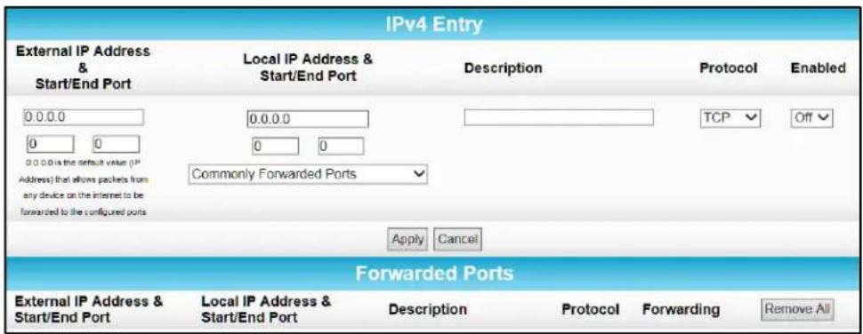
Figure 44 - Add Forwarded Ports Screen
-
Do either of the following to set up the External IP Address:
-
Keep the IP Address set at 0.0.0.0 in the External IP Address field and then enter the port number in the Start Port field. Repeat the same port number in the End Port field (select a specific port from the Commonly Forwarded Ports drop-down list, see Figure 45).
• This allows incoming data traffic on the specified ports from any remote IP address. - Enter a specific remote IP address of your choice in the External IP Address field and then enter the specific port numbers in the Start and End Port fields (select a specific port from the Commonly Forwarded Ports drop-down list, see Figure 45).
- This allows incoming data traffic on the specified ports from only one remote IP address.
Note: To forward a range of ports, enter the first number of the port range in the Start Port field and the last number of the port range in the End Port field.
- Do the following to set up your Local IP Address:
a. Enter the IP address of your local computer that you are setting up for port forwarding.
b. Enter the port number of your choice in the Start Port field. Repeat the same port number in the End Port field (select a specific port from the Commonly Forwarded Ports drop-down list, see Figure 45).
Note To forward a range of ports, enter the first number of the port range in the Local Start Port field and the last number of the port range in the Local End Port field.
- Enter a description to name the forwarded port you are creating.
- Select TCP, UDP, or BOTH from the Internet Protocol drop-down list.
-
Select On or Off from the Enabled drop-down list to enable or disable port forwarding.
-
Click Apply.
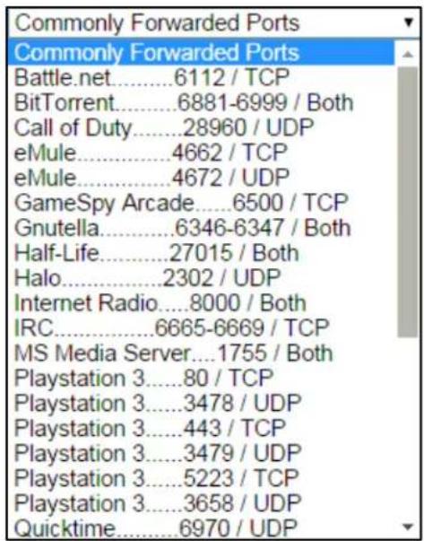
Figure 45 – Commonly Used Forwarded Ports List
Set Up the DMZ Host
WARNING! The gaming DMZ host is not protected by the SBG6400 gateway firewall. It is exposed to the Internet and thus vulnerable to attacks or hacking from any computer on the Internet. Consider carefully before configuring a device to be in the DMZ.
You can configure one computer on your home network to be the DMZ Host. That computer will operate outside of the SBG6400 firewall and allow remote access from the Internet to your computer, gaming device, or other IP-enabled device. The DMZ Host feature will only allow outside users to have direct access to the designated DMZ Host device and not your home network. See DMZ Host for more information.
To create the DMZ Host:
- Click Advanced on the SBG6400 Main Menu bar.
- Click DMZ Host from the Advanced submenu options.
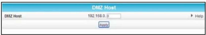
Figure 46 - Advanced DMZ Host Screen
-
Enter the last one to three digits (from 2 to 254) of the IP address of the computer or gaming device that you are setting up as the DMZ host.
-
Click Apply.
Note Remember to reset the IP address back to 0(zero) to close all the ports when you are finished with the needed application. If you do not reset the IP address, that computer will be exposed to the public Internet.
Store Remote Firewall Logs
You can store firewall attack reports or logs on a computer in your home, so that multiple instances can be logged over a period of time. You can select individual attack or configuration items to send to the SysLog server, so that only the items of interest will be monitored.
Note: The SysLog server must be on the same network as the Private LAN behind the Configuration Manager (typically 192.168.0.x).
To store remote Firewall logs:
- Click the Firewall-Remote Log menu link or click the Firewall menu button on the SBG6400 Main Menu and then select Remote Log.
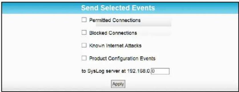
Figure 47 – Firewall Remote Log Screen
-
Select all desired event types that you want to monitor. This will activate the SysLog monitoring feature.
-
Enter the last digits from 10 to 254 of the SysLog server's IP address. Note Normally, the IP address of this SysLog server is hard-coded so that the address always agrees with the entry on this page.
-
Click Apply.
8
Managing Your Gateway and Connected Networks
View the Gateway Status and Network Connection
You can use the Device Status button on the SBG6400 Login screen to view the current gateway configuration and network connection status of your SBG6400 without having to login to the SBG6400 Web Manager.
- Open any web browser on the computer connected to the SBG6400.
- Type the default LAN IP address, 192.168.0.1, in the address bar and then press Enter. The gateway Login screen displays.
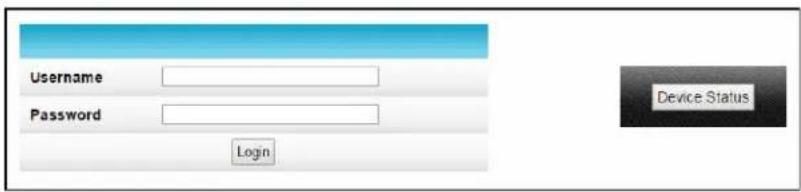
Figure 48 - Device Status Button
- Click Device Status button to open the SBG6400 Device Status screen.
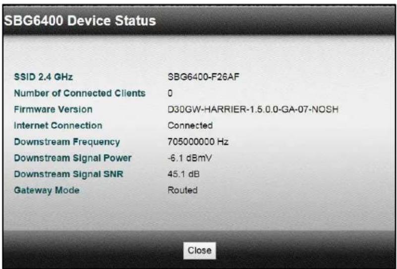
Figure 49 - Device Status Screen
View the Gateway Product Information
The Status Product Information screen displays general product information, including the firmware version and the current network connection status of the gateway.
To open the Status Product Information page:
- Click Status on the SBG6400 Main Menu.
- Click Product Information from the Status submenu options.
- Click the Refresh button (F5) in your web browser to reload the information on the screen.
| Information | |
| Standard Specification Compliant | DOCSIS 3.0 |
| Hardware Version | 1 |
| Software Version | D30GW-HARRIER-1.5.0.0-GA-07-NOSH |
| Cable Modem MAC Address | 94:62:69:ef.26:af |
| Serial Number | 401383423100019351511111 |
| Status | |
| Up Time | 3 days 08h;18m:20s |
| Cable Modem IP Address | ---,---,---,--- |
Figure 50 - SBG6400 Status - Product Information Screen
View the Gateway Status
The Status Connection screen displays information about the RF upstream and downstream channels, including downstream channel frequency, upstream channel ID, and upstream and downstream signal power and modulation.
This screen also displays IP lease information including the current IP address of the gateway, the duration of both leases, the expiration time of both leases, and the current system time from the DOCSIS time server.
To open the Status Connection screen:
- Click Status on the SBG6400 Main Menu.
- Click Connection from the Status submenu options.
| Startup Procedure | ||||||||
| Procedure Status Comment | ||||||||
| Acquire Downstream Channel Locked | ||||||||
| Connectivity State OK Operational | ||||||||
| Boot State OK Operational | ||||||||
| Configuration File OK | ||||||||
| Security Enabled BPI+ | ||||||||
| DOCSIS Network Access Enabled Allowed | ||||||||
| Downstream Bonded Channels | ||||||||
| Channel | Lock Status | Modulation | Channel ID | Frequency | Power | SNR | Corrected | Uncorrectables |
| 1 | Locked | QAM256 | 1 | 705000000 Hz | -6.1 dBmV | 45.4 dB | 1 | 0 |
| 2 | Locked | QAM256 | 2 | 711000000 Hz | -6.2 dBmV | 44.7 dB | 1 | 0 |
| 3 | Locked | QAM256 | 3 | 717000000 Hz | -6.2 dBmV | 44.6 dB | 1 | 0 |
| 4 | Locked | QAM256 | 4 | 723000000 Hz | -6.1 dBmV | 44.6 dB | 4 | 0 |
| 5 | Locked | QAM256 | 5 | 729000000 Hz | -6.5 dBmV | 43.9 dB | 2 | 0 |
| 6 | Locked | QAM256 | 6 | 735000000 Hz | -6.5 dBmV | 44.6 dB | 4 | 0 |
| 7 | Locked | QAM256 | 7 | 741000000 Hz | -6.8 dBmV | 44.6 dB | 1 | 0 |
| 8 | Locked | QAM256 | 8 | 747000000 Hz | -6.7 dBmV | 44.6 dB | 1 | 0 |
| Upstream Bonded Channels | ||||||||
| Channel | Lock Status | US Channel Type | Channel ID | Symbol Rate | Frequency | Power | ||
| 1 | Locked | ATDMA | 3 | 5120 Ksym/sec | 23300000 Hz | 47.5 dBmV | ||
| 2 | Locked | ATDMA | 1 | 5120 Ksym/sec | 30700000 Hz | 47.5 dBmV | ||
| 3 | Locked | TDMA and ATDMA | 2 | 2560 Ksym/sec | 18500000 Hz | 47.3 dBmV | ||
| 4 | Locked | TDMA and ATDMA | 4 | 2560 Ksym/sec | 35500000 Hz | 47.3 dBmV | ||
Upstream Bonded Channels
Figure 51 – SBG6400 Status Connection Screen
Back Up Your Gateway Configuration
You can save a backup copy of the current gateway settings to your local computer. You can use the backup file to restore your custom gateway settings in the event that you made changes that you no longer want.

ARRIS recommends that you perform the gateway configuration backup using the SBG6400 default login username and password.
To create a back up copy of your gateway settings:
- Click Basic on the SBG6400 Main Menu.
- Click Backup and Restore from the Basic submenu options.
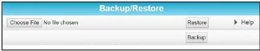
Figure 52 - SBG6400 Backup and Restore Screen
- Click Backup and then click OK at the Select 'Save' prompt (see screen below) to back up your SBG6400 configuration settings.
- GatewaySettings.bin is the backup gateway configuration file that is downloaded to your computer.
- Note: GatewaySettings.bin is the default file name for your gateway configuration file.
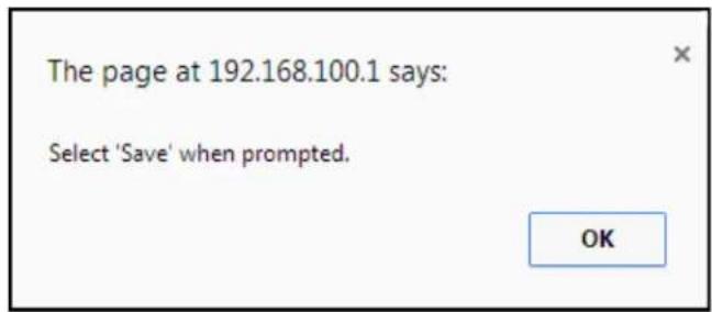
- Right-click on the configuration file name at the bottom of your screen and then select Show in folder to open the Downloads folder on your computer.
- The backup SBG6400 configuration file was saved to the Downloads folder.
Restore Your Gateway Settings
WARNING! This action will delete your current gateway configuration settings (including any custom user name and/or password) and allow you to restore a previously saved gateway configuration.
Note: After the configuration settings are restored, the gateway will reboot and you will have to log on using the default username (admin) and password (password).
- Click Basic on the SBG6400 Main Menu.
-
Click Backup and Restore from the Basic submenu options.
-
Click Choose File to search for a previously saved gateway configuration file from the Downloads folder on your computer.
- Select the GatewaySettings.bin file that you want restored on your SBG6400 and then click Open.
- Click Restore and then click OK at the reboot message prompt (see below) to reboot the SBG6400 and restore your SBG6400 configuration settings.
Note: Click Cancel if you have not saved your current SBG6400 configuration and do not want to lose it.
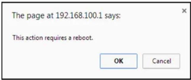
Reset Your Gateway Settings
At any time, you can reset the SBG6400 gateway configuration settings and your user name and password back to the default factory settings. There are two methods available for resetting the gateway configuration settings on the SBG6400:
• Using the SBG6400 Reset button, see Reset button
• Using the SBG6400 Web Manager (this section)
WARNING! This process also deletes any custom gateway configurations you may have already created. ARRIS recommends that you create a backup copy of your gateway configuration before resetting the gateway. See Back Up Your Gateway Configuration for more information.
From the SBG6400 Web Manager, do the following to open the Status Security screen:
- Click Status on the SBG6400 Main Menu.
- Click Security from the Status submenu options.
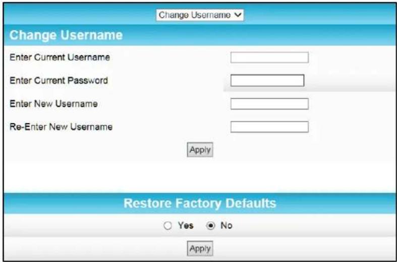
Figure 53 – Restore Factory Defaults Screen
- Select Yes under Restore Factory Defaults.
- Click Apply to reset the default username and password, and restore the original gateway configuration.
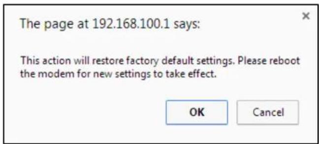
- Click OK.
- Click Status on the SBG6400 Main Menu.
- Click Configuration from the Status submenu options to display the Status Configuration screen.
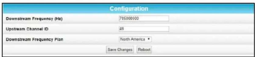
Figure 54 – Status Configuration Screen
- Click Reboot.
- Log back in using the default username and password.
- Username: admin
- Password: password
Note: For network security purposes, ARRIS recommends that you change the gateway default username and password. See Change the Default User Name and Password for more information.
Set Up Your USB Storage Device
The SBG6400 has one USB 2.0 port that can only be used to connect a USB hard drive or flash drive. The removable USB storage device will be available to all the computers or other network devices connected to your home network. This allows you to share various types of text and graphic files, as well as multimedia content (videos, music, photos) with family, friends, and other users (local or remote) on your home network.
- Check that your USB device is properly connected to the USB port on the rear of the SBG6400 and powered on.
The USB LED on the front panel should light up solid green.
- Log in to the SBG6400 Web Manager.
- Click Basic on the SBG6400 Main Menu.
- Click USB Connect from the Basic submenu options.
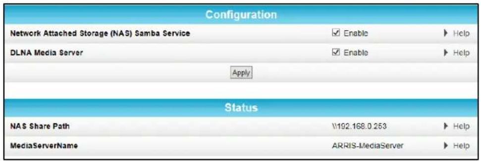
Figure 55 - SBG6400 USB Connect Screen
- Select Enable in the Network Attached Storage (NAS) Samba Service field to enable your connected USB device on your home network.
- Select Enable in the DLNA Media Server field to make your connected USB device accessible to the other devices on your home network.
- Click Apply.
A
Troubleshooting Tips
If the solutions listed in this section do not solve your problem, contact your service provider for assistance.
Your service provider may ask for the status of the front panel LEDs as described in Front Panel LED Icons and Error Conditions.
You may have to reset the SBG6400 gateway configuration to its original factory settings if the gateway is not functioning properly.
Solutions
Table 5: Troubleshooting Solutions
| Gateway Problem | Possible Solution |
| Power LED Icon is OFF | Check the power connection between the gateway and electrical wall outlet.If the gateway is plugged into a power strip, check the power strip to make sure it is switched ON.Check that the electrical wall outlet is working and that it is not controlled by a light switch.If so, disconnect the gateway power cord from the wall outlet and connect it to another electrical outlet that is not controlled by a light switch. |
| Cannot Access the Internet | Check that all cable and power connections on the gateway and computer are properly connected.Check that the Power, Online, and Wireless LEDs on the gateway front panel are lit (solid).Check or update the latest drivers for your network adapters.If none of the above solutions resolved the problem, contact your service provider or call ARRIS Technical Support at 1-877-466-8646 for assistance. |
| Cannot Send or Receive Data | Check each end of the coaxial cable connection on the gateway and cable wall outlet. Hand tighten each connector, if necessary.Check the Ethernet cable to make sure it is properly connected to the gateway and computer. |
| Cannot Send or Receive Data (continued) | Check the status of the front panel LEDs on the gateway and then refer to Front Panel LED Icons and Error Conditions to identify the problem.If you have cable television service, check your television to ensure your cable service is operating properly.If none of the above solutions resolve the problem, contact your service provider or call ARRIS Technical Support at 1-877-466-8646 for further assistance. |
| Wireless devices cannot send or receive data | Check that the Wireless LED on the gateway front panel is lit (solid).Check that the coaxial cable connections are connected properly. Then, check your IP address. If the problem still persists, check the Wireless Security setting on the Wireless Primary Network Settings screen.If you enabled the WPA Wireless Security mode and configured a passphrase (wireless network password) on the gateway, check that each affected wireless client has the identical passphrase. If this does not resolve the problem, check if the wireless client supports the type of WPA security configured on the gateway. |
Front Panel LED Icons and Error Conditions
The SBG6400 front panel LED icons provide status information for the following error conditions:
Table 6: Front Panel LED Icons and Error Conditions
| LED Icon | Status | If, During Startup: | If, During Normal Operation: |
 POWER POWER | Off Gateway is not properly plugged into the electrical outlet | Gateway is unplugged | |
 RECEIVE RECEIVE | Blinking Downstream receive channel cannot be acquired | Downstream channel is lost | |
 SEND SEND | Blinking Upstream send channel cannot be acquired | Upstream channel is lost | |
| [4746]ONLINE | Blinking | IP registration is unsuccessful | IP registration is lost |
| [5470]WIRELESS | Off | Wireless networking is disabled or wireless device is not detected | Wireless device is not connected to the network |
 | Off | USB device is not detected | USB device is not connected |
B
Gateway Configuration Screen Definitions
This section provides detailed field definitions for the following ARRIS SBG6400 network configuration screens:
- Basic
- Advanced
- Firewall
Basic Screens
- Setup
DHCP
• DDNS - Backup and Restore
- USB Connect
Setup
You can use the SBG6400 Basic Setup screen to configure basic SBG6400 IP-related configuration data, including your local network configuration, and WAN connection type.
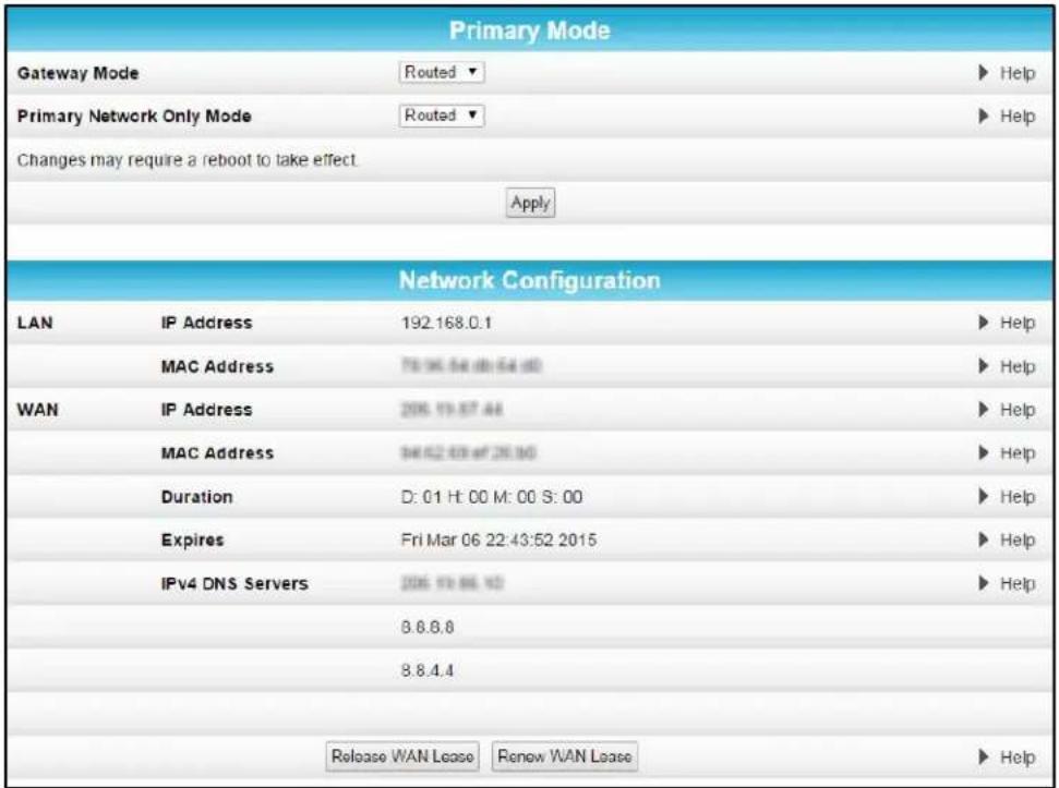
Figure 56 – Basic Setup Screen (1 of 2)
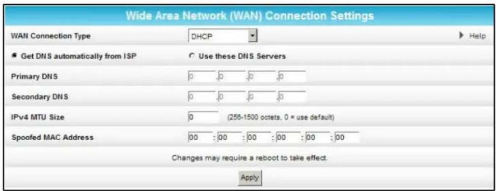
Figure 57 – Basic Setup Screen (2 of 2)
Table 7: Basic Setup Screen - Field Descriptions
| Field | Description |
| Primary Mode | |
| Gateway Mode | Sets the operating mode for the network devices on your home network. Routed - private IP addresses are assigned to your network devices. Bridged - public IP addresses are assigned to your network devices. |
| Primary Network Only Mode | Controls the operating mode (Routed and Bridged) for your primary network (Ethernet, USB, primary SSID, and MoCA). |
| Network Configuration | |
| LAN | |
| IP Address | The IP address for the SBG6400 on your home network (LAN). |
| MAC Address | Media Access Control (MAC) address — unique hardware address assigned to the SBG6400 on your home network. |
| WAN | |
| IP Address | The public WAN IP address for your SBG6400, which is either dynamically or statically assigned by the cable company. |
| MAC Address | Media Access Control address — unique address assigned to the SBG6400 on the cable company's network. |
| Duration | The length of time that the cable system lends an IP address to the SBG6400. The WAN lease is renewed when the SBG6400 requests the to be reset before it expires. |
| Expires | Displays the exact date and time the WAN lease expires. |
| IPv4 DNS Servers | The IP addresses of the servers that convert the website names into Internet addresses. |
| Release WAN Lease | Releases the IP address back to the service provider's DHCP server. |
| Renew WAN Lease | Requests that the cable company reset the timer for the IP address. |
| WAN Connection Type | Select DHCP, Static IP address, L2TP (dhcp)-Layer 2 Tunneling Protocol with DHCP, or L2TP (static)- Layer 2 Tunneling Protocol with a static IP address. |
DHCP
You can use the Basic DHCP (Dynamic Host Configuration Protocol) screen to configure the IP settings of your SBG6400 gateway and the DHCP server on your home network. You can also view the status of the optional internal SBG6400 DHCP server.
WARNING! Do not modify these setting unless you are an experienced network administrator with a strong understanding of IP addressing, sub-netting, and DHCP.
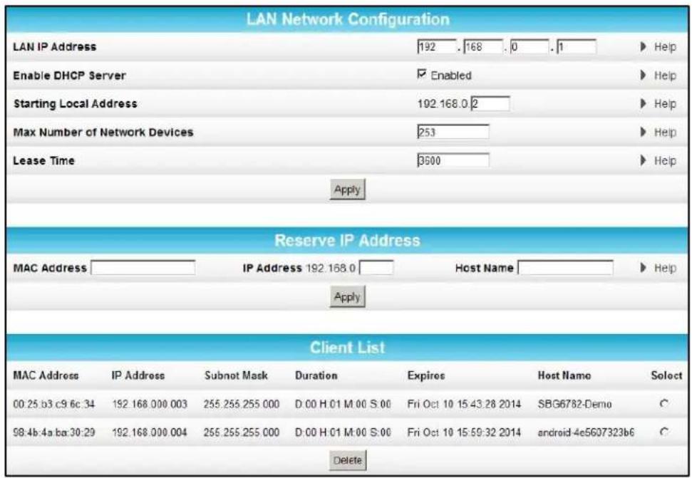
Figure 58 - Basic DHCP Screen
Table 8: Basic DHCP Screen - Field Descriptions
| Field | Description |
| LAN Network Configuration | |
| LAN IP Address | The IP address of the SBG6400 on your home network (LAN). |
| Enable DHCP Server | Checkmark Enabled to enable the SBG6400 DHCP Server. Uncheck Enabled to disable the SBG6400 DHCP Server. |
| Starting Local Address | This is the starting IP address that the SBG6400 DHCP server automatically assigns to devices on your home network. Default is 192.168.0.2. |
| Ending Local Address | This is the last IP address that the SBG6400 DHCP server automatically assigns to a device on your home network. |
| Lease Time | Sets the time in seconds that the SBG6400 DHCP server leases an IP address to a client. The default is 3600 seconds (60 minutes). |
| Reserve IP Address | Lists clients in which the DHCP server reserves a specific IP address on the home network (LAN) |
| Client List | Lists the IP address that was assigned by the DHCP server. |
DDNS
You can use the Basic DDNS (Dynamic Domain Name System) screen to set up the DDNS service to assign a static Internet domain name to a dynamic IP address. This allows various servers on the Internet to access your computer for processing your requests when you are visiting various Internet sites.
Note DDNS is a paid service that requires a registration and applicable account.
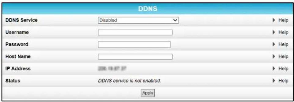
Figure 59 - Basic DDNS Screen
Table 9: Basic DDNS Screen - Field Descriptions
| Field | Description |
| DDNS Service | Select Disabled to turn off the DDNS service .Select wwwDynDNS.org to enable the DDNS service |
| Username | Enter your user name for the Dynamic Domain Name system |
| Password | Enter your password for the Dynamic Domain Name system |
| Host Name | Enter the host name for the Dynamic Domain Name system |
| IP Address | Displays the IP address |
| Status | Shows if the DDNS service is Enabled or Disabled |
Backup and Restore
You can use the Basic Backup and Restore screen to save a backup copy of the current SBG6400 gateway configuration settings locally on your computer or restore previously saved gateway configurations.
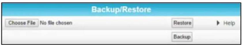
Figure 60 – Basic Backup & Restore Screen
Table 10: Basic Backup & Restore - Field Descriptions
| Field | Description |
| Browse | Allows you to search for a file on your computer to retrieve or save the gateway configuration. |
| Restore | Restores a previously saved gateway configuration. |
| Backup | Creates a back up copy of the current gateway configuration. |
USB Connect
You can use the Basic USB Connect screen to obtain configuration and status information for available applications when a storage device is connected to the USB port on the SBG6400.
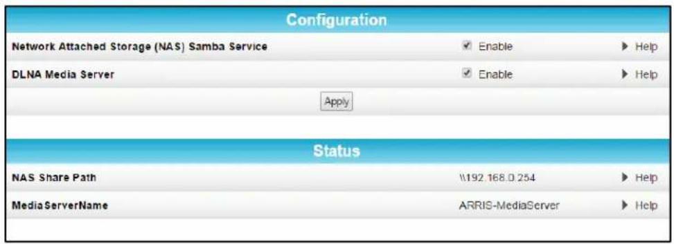
Figure 61 – Basic Backup & Restore Screen
Table 11: Basic USB Connect - Field Descriptions
| Field | Description |
| Configuration | |
| Network Attached Storage Samba Service | Enables or disables the network attached storage SAMBA service on the SBG6400. The data on the removable storage device will be accessible to the LAN with read-write permissions. |
| DLNA Media Server | Enables or disables the DLNA Media Server on the SBG6400.The data on the USB device connected to the SBG6400 will be accessible to any LAN device using a DLNA-certified player or device. |
| Status | |
| NAS Share Path | Network path used to connect to the network attached storage (NAS) Samba service from your home network. |
| MediaServerName | Server used to play the media contents of an external storage device connected on your home network. |
Advanced Screens
- Options
- IP Filtering
- MAC Filtering
- Port Filtering
- Port Triggers
- Port Forwarding
- DMZ Host
Options
You can use the Advanced Options to set the operating modes for adjusting how the SBG6400 routes IP traffic on your home network.
| WAN Blocking | Enable |
| IPsec Pass-through | Enable |
| PPTP Pass-through | Enable |
| Remote Config Management | Enable |
| Multicast Enable | Enable |
| UPnP Enable | Enable |
| NAT ALG Status | |
| FTP | Enable |
| TFTP | Enable |
| Kerb88 | Enable |
| Kerb1293 | Enable |
| ICQ | Enable |
| ICQTalk | Enable |
| IRC665x | Enable |
| IRC7000 | Enable |
| IRC8000 | Enable |
| H225 | Enable |
| RSVP | Enable |
| NetBios | Enable |
| MSN | Enable |
| PPTP | Enable |
| Net2Phone | Enable |
| RTSP | Enable |
| IKE | Enable |
| SIP | Enable |
| Apply | |
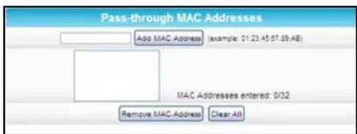
Figure 62 – Advanced Options Screen
Table 12: Advanced Options - Field Descriptions
| Field | Description |
| WAN Blocking | Prevents the SBG6400 Web Manager or the computers behind it from being visible to other computers on the SBG6400 WAN. |
| IPsec Pass-through | Enables the IPsec Pass-through protocol to be used through the SBG6400 Web Manager so that a VPN device (or software) may communicate properly with the WAN. |
| PPTP Pass-through | Enables the Point-to-Point Tunneling Protocol (PPTP)Pass-through protocol to be used through the SBG6400 Web Manager so that a VPN device (or software) may communicate properly with the WAN. |
| Remote Config Management | Allows remote access to the SBG6400 Web Manager. This enables you to configure the SBG6400 WAN by accessing the WAN IP address at Port 8080 of the SBG6400 Web Manager from anywhere on the Internet.For example, in the Internet browser URL window, type http://WanIPAddress:8080/ to access the SBG6400 Web Manager remotely. |
| Multicast Enable | Allows multicast-specific traffic (denoted by a multicast specific address) to be passed to and from the computers on the home network (LAN) behind the SBG6400 Web Manager. |
| UPnP Enable | Turns on the Universal Plug and Play protocol (UPnP) agent in the SBG6400 Web Manager.Select this option, if you are running a CPE (client) application that requires UPnP. |
| NAT ALG Status | Turn ON or OFF the various Network Address Translation (NAT) and Application Level Gateway (ALG) status options on your wireless network |
| Add MAC Address | Enter the MAC address for the computer you want to block and click Add MAC Address button.Repeat for up to 20 MAC addresses. |
| Remove MAC Address | Enter the MAC address filter that you want to delete or block, then click Remove MAC Address button. |
| Clear All button | Deletes all of your MAC Address filters. |
IP Filtering
IP filtering allows you to define which local computers will be denied access to the SBG6400 WAN. You can configure IP address filters to block Internet traffic to specific network devices on your home network by entering the starting and ending IP address ranges.
Note You only have to enter the LSB (Least-significant byte) of the IP address; the upper bytes of the IP address are set automatically from the SBG6400 Web Manager's IP address.
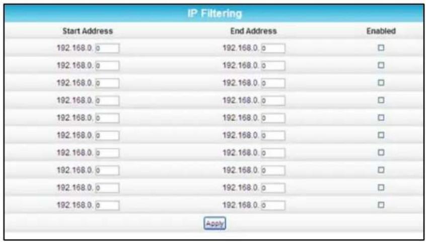
Figure 63 - Advanced IP Filtering Screen
Table 13: Advanced IP Filtering - Field Descriptions
| Field | Description |
| Start Address | Enter the starting IP address range of the computers for which you want to deny access to the SBG6400 WAN.Be sure to only enter the least significant byte of the IP address. |
| End Address | Enter the ending IP address range of the computers you want to deny access to the SBG6400 WAN.Be sure to only enter the least significant byte of the IP address. |
| Enabled | Activates the IP address filter, when selected.Select Enabled for each range of IP addresses you want to deny access to the SBG6400 WAN.When done, clickApplyto activate and save your settings. |
MAC Filtering
MAC filtering allows you to define up to 20 Media Access Control (MAC) address filters to prevent computers from sending outgoing TCP/UDP traffic to the WAN via their MAC addresses. This is useful because the MAC address of a specific NIC card never changes, unlike its IP address, which can be assigned via the DHCP server or hard-coded to various addresses over time.
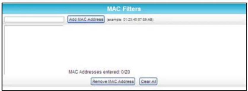
Figure 64 – Advanced MAC Filtering Screen
Table 14: Advanced MAC Filtering - Field Descriptions
| Field | Description |
| Add MAC Address | Enter the MAC address for the computer you want to block and click Add MAC Address button.Repeat for up to 20 MAC addresses. |
| Remove MAC Address | Enter the MAC address filter that you want to delete block and click Remove MAC Address button. |
| Clear All button | Deletes all of your MAC Address filters. |
Port Filtering
Port filtering allows you to define port filters to prevent all devices from sending outgoing TCP/UDP traffic to the WAN on specific IP port numbers. By specifying a starting and ending port range, you can determine what TCP/UDP traffic is allowed out to the WAN on a per-port basis.
Note The specified port ranges are blocked for ALL computers, and this setting is not IP address or MAC address specific. For example, if you want to block all computers on your home network from accessing HTTP sites (or web surfing), you would create the following port filter and then clickApply.
- Set Start Port to 80
-
Set End Port to 80
-
Set Protocol to TCP
- Select Enabled
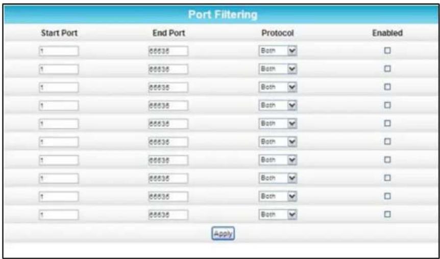
Figure 65 - Advanced Port Filtering Screen
Table 15: Advanced Port Filtering - Field Descriptions
| Field | Description |
| Start Port | The starting port number of the Port Filtering range. |
| End Port | The ending port number of the Port Filtering range. |
| Protocol | Select TCP, UDP, or BOTH from the drop-down list. |
| Enabled | Select to activate or deselect to deactivate the selected IP port triggers. |
Port Triggers
You can use Port Triggers to configure dynamic triggers to specific devices on the LAN. This allows special applications that require specific port numbers with bi-directional traffic to function properly. Applications such as video conferencing, voice, gaming, and some messaging program features may require these special settings.
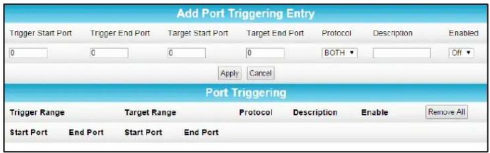
Figure 66 - Advanced Port Triggers Screen
Table 16: Advanced Port Triggers - Field Descriptions
| Field | Description |
| Trigger Start Port | The starting port number of the Port Trigger range. |
| Trigger End Port | The ending port number of the Port Trigger range. |
| Target Start Port | The starting port number of the Port Target range. |
| Target End Port | The ending port number of the Port Target range. |
| Protocol | Select TCP, UDP, or BOTH from the drop-down list. |
| Description | Name the port trigger. |
| Enabled | Select On or Off to activate or deactivate the selected IP port triggers. |
Port Forwarding
Port forwarding allows you to run a publicly accessible server on your home network by specifying the mapping of TCP/UDP ports to a local computer. This enables incoming requests on specific port numbers to reach web servers, FTP servers, mail servers, etc. so that they can be accessible from the Internet.
To map a port, you must enter the range of port numbers that want forwarded locally and the IP address to which traffic to those ports should be sent. If you only want a single port specification, enter the same port number in the start and end locations for that IP address.
A table of commonly used port numbers is also displayed on the page for your convenience. These are some of the ports used by common applications.
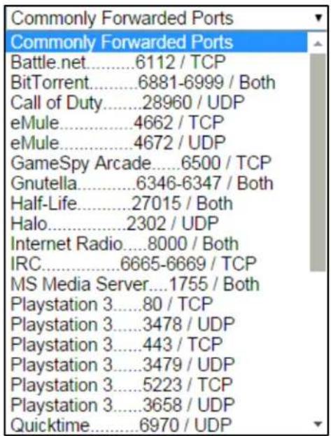
Figure 67 – Commonly Used Port Forwarding Port Numbers List
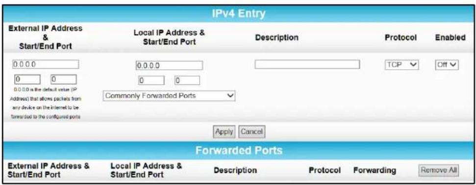
Figure 68 - Advanced Port Forwarding Screen
Table 17: Advanced Port Forwarding - Field Descriptions
| Field | Description |
| External IP Address & Start/End Port | Single port: Remote IP address and a specific port number (enter the same port number in the Start and End Port fields).Range of ports: Remote IP address and a specific range of port numbers (enter the first and last port numbers of the desired port range in the Start and End Port fields). |
| Local IP Address & Start/End Port | Single port: IP address of the local computer or device and a specific port number (enter the same port number in the Start and End Port fields).Range of ports: IP address of the local computer or device and a specific range of port numbers (enter the first and last port numbers of the desired port range in the Start and End Port fields). |
| Description | Name of the forwarded port. |
| Protocol | Select TCP, UDP, or Both for the Internet protocol. |
| Enabled | Select On or Off to enable or disable port forwarding on the selected port(s). |
| Commonly Forwarded Ports | List of port numbers used by common applications. |
DMZ Host
You can configure one computer on your home network as the DMZ Host. The computer will not operate outside of the SBG6400 firewall. This allows all port forwarding requests to go through the DMZ Host. You can set up a separate subnetwork for remote access from the Internet to your computer, gaming devices, or other IP-enabled device so that your home network is not exposed to hackers or other external attacks from the Internet. Outside users will only have direct access to the designated DMZ Host device and not your home network.
If you set up a computer as the DMZ Host, remember to set the IP address back to zero (0) when you are finished with the needed application, since this computer will be exposed to the Internet. Although the computer is protected from Denial of Service (DoS) attacks via the SBG6400 firewall, it is still exposed to the Internet.

Figure 69 - Advanced DMZ Host Screen
Table 18: Advanced DMZ Host - Field Descriptions
| Field | Description |
| DMZ Host | Enter the IP address of the selected computer you are setting up as the DMZ host. |
Firewall Screens
- Protection Level
- Parental Control
- Local Log
- Remote Log
The firewall is already configured on the SBG6400. You can configure additional firewall filters and firewall alert notifications for your home network. The SBG6400 firewall protects your wireless LAN from hackers and other unwanted attacks or intrusions from the Internet. Firewall protection also provides the following benefits:
- Advanced, integrated stateful-inspection firewall supporting intrusion detection, session tracking, and denial-of-service attack prevention.
- Maintains state data for every TCP/IP session on the OSI network and transport layers.
- Monitors all incoming and outgoing packets and applies the firewall policy to each one; also, screens for improper packets and intrusion attempts.
-
Generates comprehensive notifications for the following:
-
User authentications
- Rejected internal and external connection requests
• Session creation and termination
• Outside attacks (intrusion detection)
Protection Level
The Firewall Protection Level screen has various settings related to blocking or exclusively allowing different types of data through the SBG6400 from the WAN to the LAN. There are three firewall protection security levels which correspond to the number of services are allowed:
• Off - No security, highest risk
• Low - Common security, higher risk
• Medium - Safer configuration, modest risk
• High - Safest configuration, highest security
Firewall protection enables the Stateful Packet Inspection (SPI) firewall features. Block Fragmented IP packets prevent all fragmented IP packets from passing through the firewall. Port Scan Detection detects and blocks port scan activity originating on both the LAN and WAN. IP Flood Detection detects and blocks packet floods originating on both the LAN and WAN.
You can block Java Applets, Cookies, ActiveX controls, pop up windows, and Proxies.
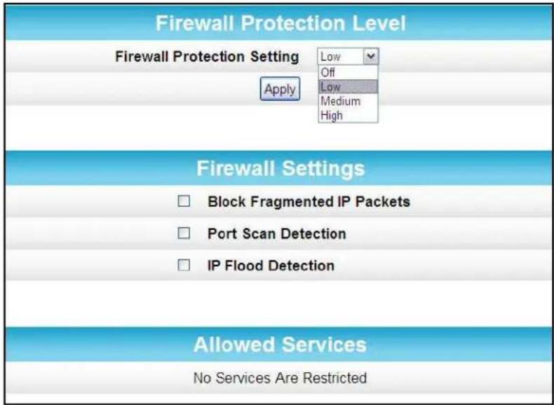
Figure 70 – Firewall Protection Level Screen
Table 19: Firewall Protection Level - Field Descriptions
| Field | Description |
| Firewall Protection Level | Select Low, Medium, or High to set the level of firewall protection that you want for your gateway.Select Off to disable firewall protection.Note:If you choose to disable firewall protection, your computer(s) and other Ethernet-enabled devices on your home network will be at risk for possible attacks from viruses and hackers. |
| Firewall Settings | Checkmark to enable each filter that you want to set for the firewall.ClickApply, when done. |
| Allowed Services | Listing of the websites you selected to allow access to from your home network. |
Parental Control
You can use the Parental Control screen to set up user access restrictions on a specific device connected to your SBG6400 network. You can set up the following Parental Controls:
- Allow or block access to specific Internet sites.
- Allow or block access to specific MAC addresses.
- Allow or block Internet access based on specific day and time settings.
- Enable or disable Internet session duration timers to limit the amount of time for Internet access.
Note When creating Parental Control access filters, remember to assign the Start and End ports. Otherwise, any filters without assigned ports will apply to all ports. This also applies to MAC addresses.
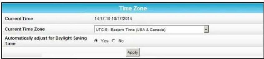
Figure 71 – Firewall Parental Control-Set Time Zone Screen
Table 20: Firewall Parental Control-Set Time Zone - Field Descriptions
| Field | Description |
| Current Time | Enter the current time. |
| Current Time Zone | Select your time zone. |
| Automatically adjust for Daylight Saving Time | Select Yes or No if you want the time to change for Daylight Saving Time. |
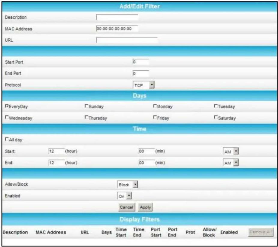
Figure 72 - Firewall Parental Control Screen
Table 21: Firewall Parental Control - Field Descriptions
| Field | Description |
| Description | Enter a name to create a new user profile. |
| MAC Address | Enter the 12-digit (hexadecimal) hardware address of the device that you are setting up for parental controls.The MAC addressed is assigned by the hardware manufacturer and should be located on the device label. |
| URL | Enter the web address of the Internet site that you want to block or access. |
| Start Port | Enter the starting port number of the range of ports for which you want to block incoming or outgoing access.Default port is 0. |
| End Port | Enter the ending port number of the range of ports for which you want to block incoming or outgoing access.Default port is 0. |
| Protocol | Select TCP, UDP, or Both for the Internet protocol. |
| Days | Select the days of the week that the selected user can access the Internet. |
| Time | Set the start and end time of day that the selected user can access the Internet. |
| Allow/Block | Set to allow or block Internet access for the time defined above. |
| Enabled | Turn ON or OFF this Parental Control restriction. |
| Time Zone | Update the related time information for your location. |
Local Log
A Local Event Log is generated when a firewall attack against the SBG6400 is detected. You can choose to receive notification of the logged firewall events in either of the following two formats:
- Individual e-mail alerts sent out automatically each time the firewall is under attack
- Local log stored within the gateway and displayed in table form on the Local Log page
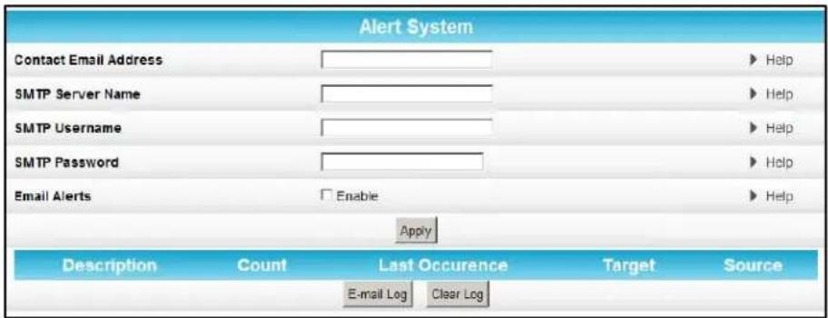
Figure 73 - Firewall Local Log Screen
Table 22: Firewall Local Log - Field Descriptions
| Field | Description |
| Contact Email Address | Your email address |
| SMTP Server Name | Name of the email Simple Mail Transfer Protocol (SMTP) serverThe firewall page requires the name of your email server for sending a firewall log to your email address. You can obtain the SMTP server name from your service provider. |
| SMTP Username | Your user name for your email account. Check with your email service provider. |
| SMTP Password | Your password for your email account. Check with your service provider. |
| Email Alerts | Enable or disable emailing firewall alerts. |
Remote Log
You can send firewall attack reports out to a standard SysLog server, so that many instances can be logged over a long period of time. You can select individual attack or configuration items to send to the SysLog server so that only the items of interest will be monitored.
There are four types of Firewall reports that you can monitor and log:
- Permitted Connections – Select to notify the server to send you email logs identifying who is connecting to your network.
- Blocked Connections – Select to notify the server to send you email logs identifying who was blocked from connecting to your network.
- Known Internet Attacks – Select to notify the server to send you email logs of known Internet attacks against your network.
- Product Configuration Events – Select to notify the server to send you email logs of the basic product configuration events logs.
The SysLog server must be on the same network as the Private LAN behind the Configuration Manager (typically 192.168.0.x).
To activate the SysLog monitoring feature, check all desired event types to monitor and enter the last byte of the IP address of the SysLog server. Normally, the IP address of this SysLog server is hard coded so that the address always agrees with the entry on this page.

Figure 74 – Firewall Remote Log Screen
Table 23: Firewall Remote Log - Field Descriptions
| Field | Description |
| Permitted Connections | Select if you want email notification of who is connecting to your network. |
| Blocked Connections | Select if you want email notification of who is blocked from connecting to your network. |
| Known Internet Attacks | Select if you want email notification of known Internet attacks against your network. |
| Product Configuration Events | Select if you want email notification of the basic product configuration events. |
| to Syslog server at 192.168.0.x | Enter the last digit(s) of your SysLog server's IP address.Possible values: 10 to 254 |
C
Warranty Information
SURFboard SBG6400 Wireless Gateway ARRIS Enterprises, Inc. ("ARRIS")
Retail Purchasers (SURFboard): If you purchased this Product directly from ARRIS or from an authorized ARRIS retail reseller, ARRIS warrants to you, the original end user customer, that (A) the Product, excluding Software, will be free from defects in materials and workmanship under normal use, and (B) with respect to Software, (i) the media on which the Software is provided will be free from defects in material and workmanship under normal use, and (ii) the Software will perform substantially as described in its documentation. This Limited Warranty to you, the original end user customer, continues (A) for Software and the media upon which it is provided, for a period of ninety (90) days from the date of purchase from ARRIS or an authorized ARRIS reseller, and (B) for the Product (excluding Software), for a period of two (2) years from the date of purchase from ARRIS or from an authorized ARRIS reseller. To take advantage of this Limited Warranty or to obtain technical support, you must call the ARRIS toll-free telephone number, 1-877-466-8646. Technical support charges may apply. ARRIS' sole and exclusive obligation under this Limited Warranty for retail sales shall be to repair or replace any Product or Software that does not meet this Limited Warranty. All warranty claims must be made within the applicable Warranty Period.
General Information. The warranties described in this Section shall not apply: (i) to any Product subjected to accident, misuse, neglect, alteration, Acts of God, improper handling, improper transport, improper storage, improper use or application, improper installation, improper testing or unauthorized repair; or (ii) to cosmetic problems or defects which result from normal wear and tear under ordinary use, and do not affect the performance or use of the Product. ARRIS' warranties apply only to a Product that is manufactured by ARRIS and identified by ARRIS owned trademark, trade name or product identification logos affixed to the Product. ARRIS does not warrant to you, the end user, or to anyone else that the Software will perform error free or without bugs.
ARRIS IS NOT RESPONSIBLE FOR, AND PROVIDES "AS IS" ANY SOFTWARE SUPPLIED BY 3RD PARTIES. EXCEPT AS EXPRESSLY STATED IN THIS SECTION ("WARRANTY INFORMATION"), THERE ARE NO WARRANTIES OF ANY KIND RELATING TO THE PRODUCT, EXPRESS, IMPLIED OR STATUTORY, INCLUDING BUT NOT LIMITED TO IMPLIED WARRANTIES OF MERCHANTABILITY, FITNESS FOR A PARTICULAR PURPOSE, OR THE WARRANTY AGAINST INFRINGEMENT PROVIDED IN THE UNIFORM COMMERCIAL CODE. Some states do not allow for the exclusion of implied warranties, so the above exclusion may not apply to you.
What additional provisions should I be aware of? Because it is impossible for ARRIS to know the purposes for which you acquired this Product or the uses to which you will put this Product, you assume full responsibility for the selection of the Product for its installation and use. While every reasonable effort has been made to insure that you will receive a Product that you can use and enjoy, ARRIS does not warrant that the functions of the Product will meet your requirements or that the operation of the Product will be uninterrupted or error-free.
ARRIS IS NOT RESPONSIBLE FOR PROBLEMS OR DAMAGE CAUSED BY THE INTERACTION OF THE PRODUCT WITH ANY OTHER SOFTWARE OR HARDWARE. ALL WARRANTIES ARE VOID IF THE PRODUCT IS OPENED, ALTERED, AND/OR DAMAGED.
THESE ARE YOUR SOLE AND EXCLUSIVE REMEDIES for any and all claims that you may have arising out of or in connection with this Product, whether made or suffered by you or another person and whether based in contract or tort.
IN NO EVENT SHALL ARRIS BE LIABLE TO YOU OR ANY OTHER PARTY FOR ANY DIRECT, INDIRECT, GENERAL, SPECIAL, INCIDENTAL, CONSEQUENTIAL, EXEMPLARY OR OTHER DAMAGES ARISING OUT OF THE USE OR INABILITY TO USE THE PRODUCT (INCLUDING, WITHOUT LIMITATION, DAMAGES FOR LOSS OF BUSINESS PROFITS, BUSINESS INTERRUPTION, LOSS OF INFORMATION OR ANY OTHER PECUNIARY LOSS), OR FROM ANY BREACH OF WARRANTY, EVEN IF ARRIS HAS BEEN ADVISED OF THE POSSIBILITY OF SUCH DAMAGES. IN NO CASE SHALL ARRIS' LIABILITY EXCEED THE AMOUNT YOU PAID FOR THE PRODUCT.
These matters are governed by the laws of the Commonwealth of Pennsylvania, without regard to conflict of laws principles and excluding the provisions of the United Nations Convention on Contracts for the International Sale of Goods.
Retail Purchasers (SURFboard). If you purchased this Product directly from ARRIS or from an ARRIS authorized retail reseller, please call the ARRIS toll-free telephone number, 1-877-466-8646, for warranty service or technical support. Technical support charges may apply. For online technical support, please visit www.arris.com/consumer.

ARRIS Enterprises, Inc.
3871 Lakefield Drive
Suwanee, GA 30024
www.arris.com
365-095-26377 x.3 07/15
