FS-L3202D - Monitor FSN - Free user manual and instructions
Find the device manual for free FS-L3202D FSN in PDF.

| Product Type | LED Monitor |
| Screen Size | 32 inches (80 cm) |
| Resolution | 1920 x 1080 (Full HD) |
| Aspect Ratio | 16:9 |
| Brightness | 250 cd/m² |
| Contrast Ratio | 3000:1 (typical) |
| Response Time | 5 ms |
| Viewing Angle | 178° / 178° |
| Refresh Rate | 60 Hz |
| Connectivity | HDMI x1, VGA x1, Audio Out x1 |
| Power Supply | AC 100-240V, 50/60Hz |
| Power Consumption (typical) | ≤60W |
| Standby Power Consumption | ≤0.5W |
| Weight (with stand) | Approx. 7.5 kg |
| Dimensions (with stand) | 730 x 480 x 200 mm |
| VESA Mount Compatibility | 100 x 100 mm |
| Included Accessories | Power cable, VGA cable, User manual |
| Cleaning Instructions | Use a soft, dry cloth; avoid solvents |
| Safety Precautions | Do not place near heat sources; ensure proper ventilation |
| Spare Parts & Repairability | Available from authorized service centers; contact FSN support |
Frequently Asked Questions - FS-L3202D FSN
User questions about FS-L3202D FSN
0 question about this device. Answer the ones you know or ask your own.
Ask a new question about this device
Download the instructions for your Monitor in PDF format for free! Find your manual FS-L3202D - FSN and take your electronic device back in hand. On this page are published all the documents necessary for the use of your device. FS-L3202D by FSN.
USER MANUAL FS-L3202D FSN
Medical Technologies
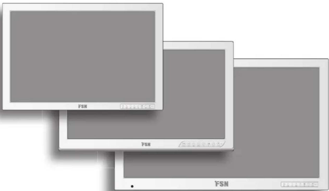
natural_image
Three computer monitors with 'FSN' branding, shown in grayscale without any text or symbols on the screens themselves.Medical Display
FS-L2402D FS-P2603D FS-P2607D (3D) FS-L3202D
User's Guide
Before connecting, operating or adjusting this product, please read this instruction booklet carefully and completely.
Table of Contents
Introduction 3
Symbol Definitions 4
Safety Instructions 6
Caution 8
FCC Information. 10
Parts 14
Connectors....15
Mechanical Drawing 16
Controls 19
Power Management 20
On Screen Display (OSD) 21
3D Control (FS-P2607D only) 27
OSD System Overview 28
Remote Control (FS-L3202D only) 31
Standard Signal Tables.... 33
Signal Connector Pin Assignments 34
General Specification 36
Cleaning Instructions 39
Contacts. 44
The specifications and information in this document are subject to change without notice.
Overview

natural_image
Black-and-white photo of medical staff in protective gear operating equipment (no visible text or symbols)FS-L2402D FS-P2603D FS-P2607D (3D) FS-L3202D
This product from FSN Medical Technologies is a high-end surgical display monitor designed for advanced digital OR applications. This medical display is uniquely equipped to handle tasks in the demanding operating room environment. The input/output options have been expanded, including dual DVI and on-board DC out power for smaller component needs. This unit features LED backlight technology.
We have implemented methods to fine-tune the properties of FSN displays. Distinct color space settings have been calibrated to well-known surgical color preferences, providing the user with the ideal surgical visualization system. Features include:
• Rapid signal detection, robust mode tables
• Artifact-free HD images
• Fanless - sterile field compatible
• Calibrated to clinical color
• Image pan, zoom, freeze, picture-in-picture
FSN Medical Technologies has solutions for managing your operating room video signals. Our products are engineered and built for compatibility with other highly specialized surgical and diagnostic equipment used in surgical suites, operating rooms, emergency rooms, and procedural facilities.
Symbol Definitions
The following symbols appear on the product, its labeling, or the product packing. Each symbol carries a special definition, as defined below:
 | Dangerous : High Voltage Power | ada |  | |
 | Direct Current |  | Indicates equipotential earth ground | |
 | Indicates protective earth ground |  | Indicates top-bottom direction | |
 | DC Power control switch Fragile |  | ||
 | Do not get wet Maximum Stacking |  | ||
 | Consult the operating instruc-tions. |  | Indicates the manufacturer | |
 | Indicates the manufacturing date |  | Authorized representative in the European community | |
 | Korea Certification Humidity limitatic |  | ||
 | Serial Number |  | Atmospheric pressure limitation | |
 | Temperature limitation |
 | Indicates proof of conformity to applicable European Economic Community Council directives and to harmonized standards published in the official journal of the European Communities. |
 | Medical Equipment is in accordance with UL 60601-1 and CAN/CSA C22.2 No. 601.1 in regards to electric shock, fire hazards, and mechanical hazard. |
 | Tested to comply with FCC Class B standard. |
 | Indicates the display is approved according to the CCC regulations. |
 | China RoHS labels. |
 | This symbol indicates that the waste of electronic equipment must not be disposed as unsorted municipal waste and must be collected separately. Please contact the manufacturer or other authorized disposal company to decommission your equipment. |
Language: English
Note: A printed copy of the manual in English is provided with the product. Users within EU member states, please contact local distributor for other languages or refer to the CD manual enclosed with the product. This applies to EU member states where the product has been purchased through authorized channels.
Safety Instructions
On Safety
- Before connecting the AC power cord to the DC adapter outlet make sure the voltage designation of the DC adapter corresponds to the local electrical supply.
- Never insert anything metallic into the cabinet openings of the medical LCD monitor. Doing so may create the danger of electric shock.
- To reduce the risk of electric shock, do not remove cover. No user-serviceable parts inside. Only a qualified technician should open the case of the medical LCD monitor.
- Never use your medical LCD monitor if the power cord has been damaged. Do not allow anything to rest on the power cord, and keep the cord away from areas where people can trip over it.
- Be sure to hold the plug, not the cord, when disconnecting the medical LCD monitor power cord from an electric socket.
- Unplug your medical LCD monitor power cord when it is going to be left unused for an extended period of time.
- Unplug your medical LCD monitor power cord from the AC outlet before any service.
- If your medical LCD monitor does not operate normally, in particular, if there are any unusual sounds or smells coming from it, unplug it immediately and contact an authorized dealer or service center.
- Please contact the manufacturer if the set should be installed in an inaccessible area.
Warning: Do not touch input or output connectors and the patient simultaneously.
Warning: This medical LCD monitor is intended for connection to input/output signals and other connectors that comply with relevant IEC standard (e.g., IEC60950 for IT equipment and IEC60601 series for medical electrical equipment). In addition, all such combination-system shall comply with the standard IEC 60601-1-1 or clause 16 of the 3 Ed. of IEC 60601-1, respectively, safety requirements for medical electrical systems. Any person who has formed a combination-system is responsible for the system to comply with the requirements of IEC 60601-1-1 or clause 16 of the 3 Ed. of IEC 60601-1, respectively. If in doubt, contact qualified technician or your local representative.
Warning: To avoid risk of electric shock, this equipment must only be connected to a supply mains with protective earth. Power supply (AC/DC Adapter) is specified as a part of the LCD Color Display. Do not to position equipment so that it is difficult to disconnect the power cord plug from the appliance inlet.
Warning: Do not modify this equipment without authorization of the manufacturer.
On installation
- Openings in the medical LCD monitor cabinet are provided for ventilation. To prevent overheating, these openings should not be blocked or covered. If you put the medical LCD monitor in a bookcase or some other enclosed space, be sure to provide adequate ventilation.
- Put your medical LCD monitor in a location with low humidity and a minimum of dust.
- Do not expose the medical LCD monitor to rain or use it near water (in kitchens, near swimming pools, etc.). If the medical LCD monitor accidentally gets wet, unplug it and contact an authorized dealer immediately. You can clean the medical LCD monitor with a damp cloth if necessary, but be sure to unplug the medical LCD monitor first.
- Place your medical LCD monitor near an easily accessible AC outlet.
- High temperature can cause problems. Don't use your medical LCD monitor in direct sunlight and keep it away from heaters, stoves, fireplaces, and sources of heat.
- Don't place your medical LCD Monitor on an unstable stand, Medical LCD monitor may malfunction or fall.
- This medical LCD monitor should not topple over when tilted at a 5^ angle, in any position, during NORMAL USE, excluding transport.
- In the position specified for transport, medical LCD monitor shall not overbalance when tilted at a 10 degree angle.
- When carrying this product, please use both handles (if included) on the left and right side of the product, and carry using two people. If you want the product to be installed in another place, please call your service center.
- Do not use other cables or accessories that are not provided.
- Do not lay this monitor on the other equipment.
Environmental Conditions for Operation and Storage
Temperature range within 0^ C to 40^ C(operation), -20^ C to 60^ C (storage)
Relative humidity range 10% to 85%
Atmospheric pressure range within 500 to 1060hPa.
Intended Use
This Medical LCD Monitor is an accessory intended for use with Medical Equipment to display alphabetical, numerical and graphical data.
Cautions
Caution

This symbol alerts the user that important literature concerning the operation of this unit been included. Therefore, it should be read carefully in order to avoid potential problems.

This symbol warns users that un-insulated voltage within the unit may have sufficient attitude to cause electrical shock. Therefore, it is dangerous to make contact with any part of the unit. To reduce the risk of electrical shock, DO NOT remove cover (or back). There are other-serviceable parts inside. Refer servicing to qualified service personnel.
To prevent fire or shock hazards, do not expose this unit to rain or moisture. Do not use this unit's polarized plug with an extension cord receptacle or other outlets unless the prongs can be fully inserted. This display is designed to meet the medical safety requirements for a patient vicinity device. This device may not be used in connection with life support equipment.

Underwriters Laboratories (UL) Classification:
UL safety Compliance:
This medical LCD monitor is U.L. Classified WITH RESPECT TO ELECTRIC SHOCK, FIRE AND MECHANICAL HAZARDS ONLY IN ACCORDANCE WITH UL 60601-1/CAN/CSA C22.2 NO. 601.1

EEC Safety Compliance:
This medical LCD monitor unit meets the requirements of EN-60601-1 so as to conform to the Medical Device Directive 93/42/EEC (general safety information). Use 120V rating 5-15P type plug only in the U.S.
This medical LCD monitor complies to the above standards only when used with the supplied medical grade power supply.
FS-L2402D / FS-P2603D / FS-P2607D / FS-L3202D - BPM150S24F10 (BRIDGE POWER CORP).
Caution: Make sure the power cord is the correct type that is required in your area. This medical LCD monitor has a universal power supply that allows operation in either 100-120V AC or 200-240V AC voltage areas (no user adjustment is required).
Use the proper power cord with correct attachment plug type. If the power source is 120 V AC, use a power cord which is a Hospital Grade Power Cord with NEMA 5-15 style plug, labeled for 125 volts AC with UL and C-UL approvals. If the power source is a 240 V AC supply, use the tandem (T blade) type attachment plug with ground conductor power cord that meets the respective European country's safety regulations.
The hospital-grade plug for medical products intended for use in Denmark has DEMKO approval and is rated 13 amps at 250Vac. Plug is recommended for use in medical applications and specifications are being added to the standard SB 107-2-D1. Plug mates with maker's Danish hospital-grade socket. Hospital sockets have slightly different shaped openings allowing only the hospital plug, not the standard Danish plug, to be inserted, to protect the ac circuit in specific medical settings.
A ground post, located on the back of the display, may be used for the purpose of grounding the display's chassis. Any such ground must be installed in accordance with applicable electrical codes. The ground post is shown on the mechanical drawing found in this user's guide.

Recycling
Follow local governing ordinances and recycling plans regarding the recycling or disposal of this equipment.
Cleaning Instructions

Follow your hospital protocol for the handling of blood and body fluids. Clean the display with a diluted mixture of mild detergent and water. Use a soft towel or swab. Use of certain detergents may cause degradation to the labels and plastic components of the product. Consult cleanser manufacturer to see if agent is compatible. Do not allow liquid to enter the display.
Servicing
Do not attempt to service the medical LCD monitor yourself, as opening or removing covers may expose you to dangerous voltages or other hazards, and will void the warranty. Refer all servicing to qualified service personnel. Unplug the medical LCD monitor from its power source and refer servicing to qualified personnel under the following conditions:
- If the power cord or plug is damaged or frayed.
- If liquid has been spilled into the medical LCD monitor.
- If objects have fallen into the medical LCD monitor.
- If the medical LCD monitor has been exposed to rain or moisture.
- If the medical LCD monitor has been subjected to excessive shock by being dropped.
- If the cabinet has been damaged.
- If the medical LCD monitor seems to be overheated.
- If the medical LCD monitor emits smoke or abnormal odor.
- If the medical LCD monitor fails to operate in accordance with the operating instructions.
Accessories
Use only accessories specified by the manufacturer, or sold with the medical LCD monitor.
Classification
- Protection against electric shock : Class I including AC/DC Adapter
- Applied Parts : No Applied Parts
- Degree of safety in the presence of flammable anesthetics mixture with air or with oxygen or with nitrous oxide. Not suitable for use in the presence of a flammable anesthetics mixture with oxygen or with nitrous oxide.
- Mode of operation : Continuous.
FCC Information
This medical LCD monitor unit has been tested and found to comply with the limits of a Class B digital device, pursuant to Part 15 of the FCC rules. These limits are designed to provide reasonable protection against interference. This monitor can radiate radio frequency energy and, if not installed and used in accordance with the instructions, it may interfere with other radio communications equipment. There is no guarantee that interference will not occur in a particular installation. If this equipment is found to cause harmful interference to radio or television reception, the user is encouraged to try to correct the interference by carrying out one or more of the following measures:
- Reorient or relocate the receiving antenna.
- Increase the distance between the medical LCD monitor and the subject of interference.
- Plug the monitor into an outlet on a different electrical circuit than that to which the subject of interference is connected.
- Consult the dealer or an experienced radio/TV technician for help.
NOTICES TO USER
This device complies with part 15 of the FCC Rules. Operation is subject to the following two conditions:
(1) this device may not cause harmful interference, and (2) this device must accept any interference received, including interference that may cause undesired operation.
FCC WARNING
This medical LCD monitor generates or uses radio frequency energy. Changes or modifications to this medical LCD monitor may cause harmful interference unless the modifications are expressly approved in the instruction manual. The user could lose authority to operate this equipment if an unauthorized change or modification is made.
PRODUCT LIFETIME
The average lifespan of this LCD monitor has been determined to be approximately 5 years, considering the LCD flat panel which has been specified with a lifetime of 50,000 hours.
- Guidance and manufacturer's declaration - electromagnetic emission
| The medical LCD monitor is intended for use in the electromagnetic environment specified below. The customer or the user of the medical LCD monitor should assure that it is used in such an environment. | ||
| Emission test Compliance | Electromagnetic | environment -guidance |
| RF EmissionsCISPR 11 | Group 1 | The medical LCD monitor uses RF energy only for its internal function. Therefore, its RF emissions are very low and are not likely to cause any interference in nearby electronic equipment. |
| RF EmissionsCISPR 11 | Class B | The medical LCD monitor is suitable for use in all establishments, including domestic establishments and those directly connected to the public low-voltage power supply network that supplies buildings used for domestic purposes. |
| Harmonic emissionsIEC 61000-3-2 | D | |
| Voltage fluctuationsIEC 61000-3-3 | Complies | |
- Guidance and manufacturer's declaration - electromagnetic immunity
| This medical LCD monitor is intended for use in the electromagnetic environment specified below.The customer or the user of the medical LCD monitor should assure that it is used in such an environment. | |||
| Immunity test IEC | 50601 Test level | Compliance level | Electromagnetic environment-guidance |
| Electrostatic discharge(ESD)IEC 61000-4-2 | 6 kV contact8 kV air | 6 kV contact8 kV air | Floors should be wood, concrete or ceramic tile. If floors are covered with synthetic material, the relative humidity should be at least 30% |
| Electrical fast transient/burstIEC 61000-4-4 | 2 kV for power supply lines1 kV for input/output lines | 2 kV for power supply lines1 kV for input/output lines | Main power quality should be that of a typical commercial or hospital environment. |
| SurgeIEC 61000-4-5 | 1 kV differential mode2 kV common mode | 1 kV differential mode2 kV common mode | Main power quality should be that of a typical commercial or hospital environment. |
| Conducted RFIEC 61000-4-6 | 3 Vrms150 kHz to 80MHz | 3 Vrms150 kHz to 80MHz | Portable and mobile RF communications equipment should be used no closer to any part of the LCD monitor, including cables, than the recommended separation distance calculated from the equation applicable to the frequency of the transmitter.Recommended separation distance : d d = [ 3,5V_1 ] Where P is the maximum output power rating of the transmitter in watts (W) |
- Guidance and manufacturer's declaration - electromagnetic immunity
| This medical LCD monitor is intended for use in the electromagnetic environment specified below.The customer or the user of monitor should assure that it is used in such an environment. | |||
| Immunity test IEC 60601 Test level | Compliance level | Electromagnetic environment-guidance | |
| Power frequency (50/60Hz) Magnetic field IEC 61000-4-8 | 3.0 A/m 3.0 A/m | Power frequency magnetic fields should be at levels characteristic of a typical location in a typical commercial or hospital environment. | |
| Voltage dips, short Interruptions and voltage variations on power supply input lines IEC 61000-4-I 1 | <5% UT(>95% dip in UT) for 0.5 cycle40% UT(60% dip in UT) for 5 cycle70% UT(30% dip in UT) for 25 cycle<5% UT(<95% dip in UT) for 5 sec. | <5% UT(>95% dip in UT) for 0.5 cycle40% UT(60% dip in UT) for 5 cycle70% UT(30% dip in UT) for 25 cycle<5% UT(<95% dip in UT) for 5 sec. | Main power quality should be that of a typical commercial or hospital environment.If the user of monitor requires continued operation during power mains interruptions, it is recommended that monitor be powered from an uninterruptible power supply or a battery.Note: UTis the A.C. mains voltage prior to application of the test level. |
| Radiated RF IEC 61000-4-3 | 3 V/m80.0 MHz to 2.5 GHz | 3 V/m80.0 MHz to 2.5 GHz | Recommended separation distance d = [ 3,5E_1 ] 80MHz to 800MHz d = [ 7E_1 ] 80MHz to 2.5GHzWhere P is the maximum output power rating of the transmitter in watts (W) according to the transmitter manufacturer and d is the recommended separation distance in meters (m). Field strengths from fixed RF transmitters, as determined by an electromagnetic site survey, should be less than the compliance level in each frequency range. |
4. Recommended separation distances between portable and mobile RF communications equipment and this medical LCD monitor.
The medical LCD monitor is intended for use in an electromagnetic environment in which radiated RF disturbances are controlled. The customer or the user of the monitor can help prevent electromagnetic interference by maintaining a minimum distance between portable and mobile RF communications equipment (transmitters) and the medical LCD monitor as recommended below, according to the maximum output power of the communications equipment.
| Rated maximum output power [W] of transmitter | Separation distance according to frequency of transmitter[m] | ||
| 150kHz to 80MHz d = [ 3,5V_1 ] | 80MHz to 800MHz d = [ 3,5E_1 ] | 800MHz to 2.5GHz d = [ 7E_1 ] | |
| V1=3Vrms E1=3V/m | E1=3V/m | ||
| 0.01 0.116 0.1 | 16 | 0.2333 | |
| 0.1 0.368 0.3 | 687 0.7378 | ||
| 1 1.166 1.16 | 60 0.2333 | ||
| 10 3.687 3.68 | 872 0.7375 | ||
| 100 11.660 1 | 1.6600 23.333 | ||
| For transmitters rated at a maximum output power not listed above, the recommended separation distance (d) in meters (m) can be estimated using the equation applicable to the frequency of the transmitter, where P is the maximum output power rating of the transmitter in watts (W) according to the transmitter manufacturer.Note 1) At 80 MHz and 800 MHz, the separation distance for the higher frequency range applies.Note 2) These guidelines may not apply in all situations. Electromagnetic propagation is affected by absorption and reflection from structures, objects and people. | |||
Parts
Monitor
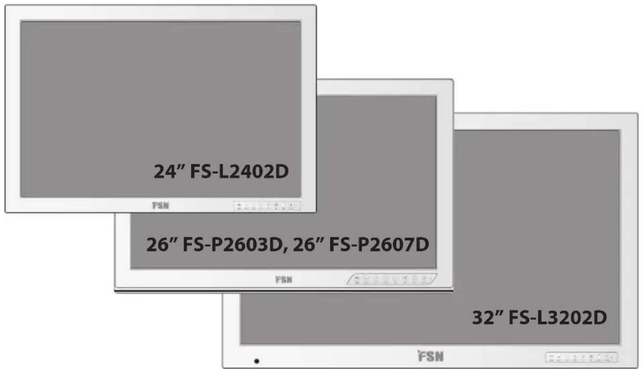
24" FS-L2402D or 26" FS-P2603D or 26" FS-P2607D or 32" FS-L3202D
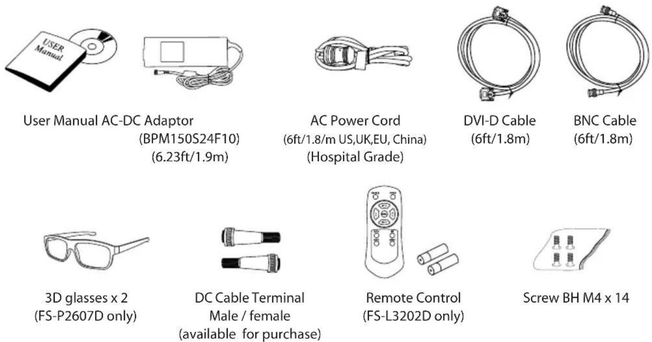
Accessories
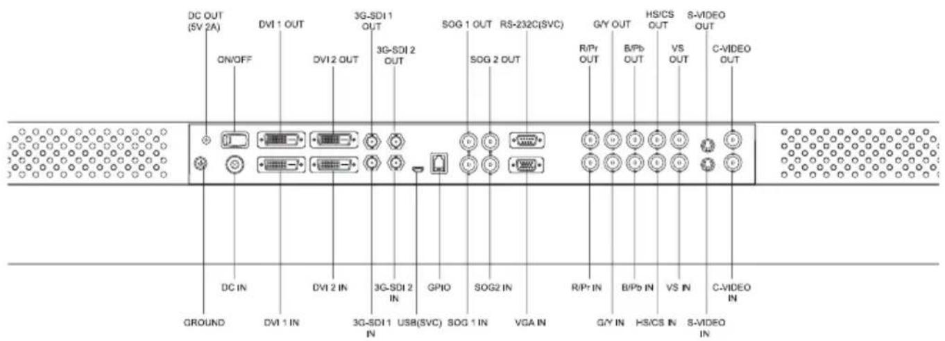
Connectors
24" FS-L2402D Monitor Connector
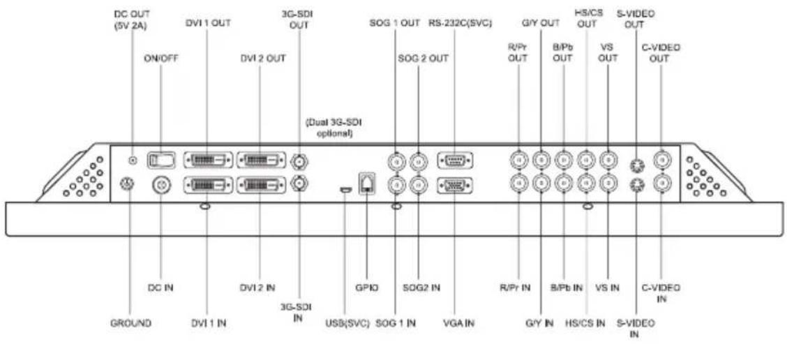
26" FS-P2603D, 26" FS-P2607D Monitor Connector
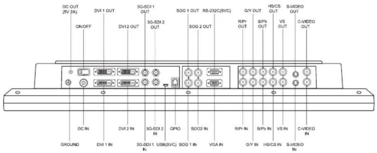
32" FS-L3202D Monitor Connector
Mechanical Product Drawing
24" FS-L2402D Dimension
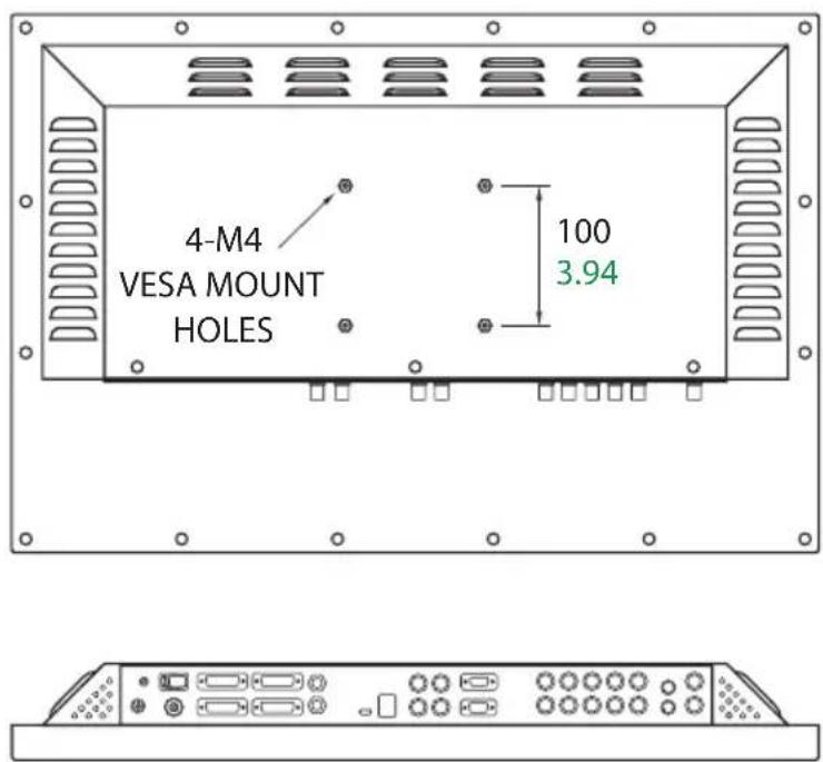
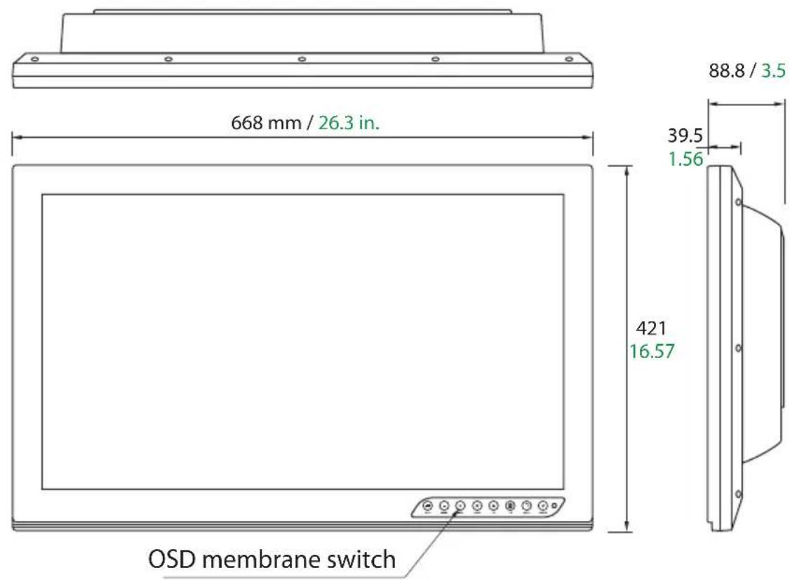
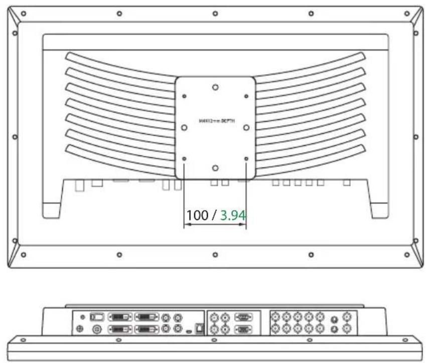
Mechanical Product Drawing
26" FS-P2603D, 26" FS-P2607D Dimension
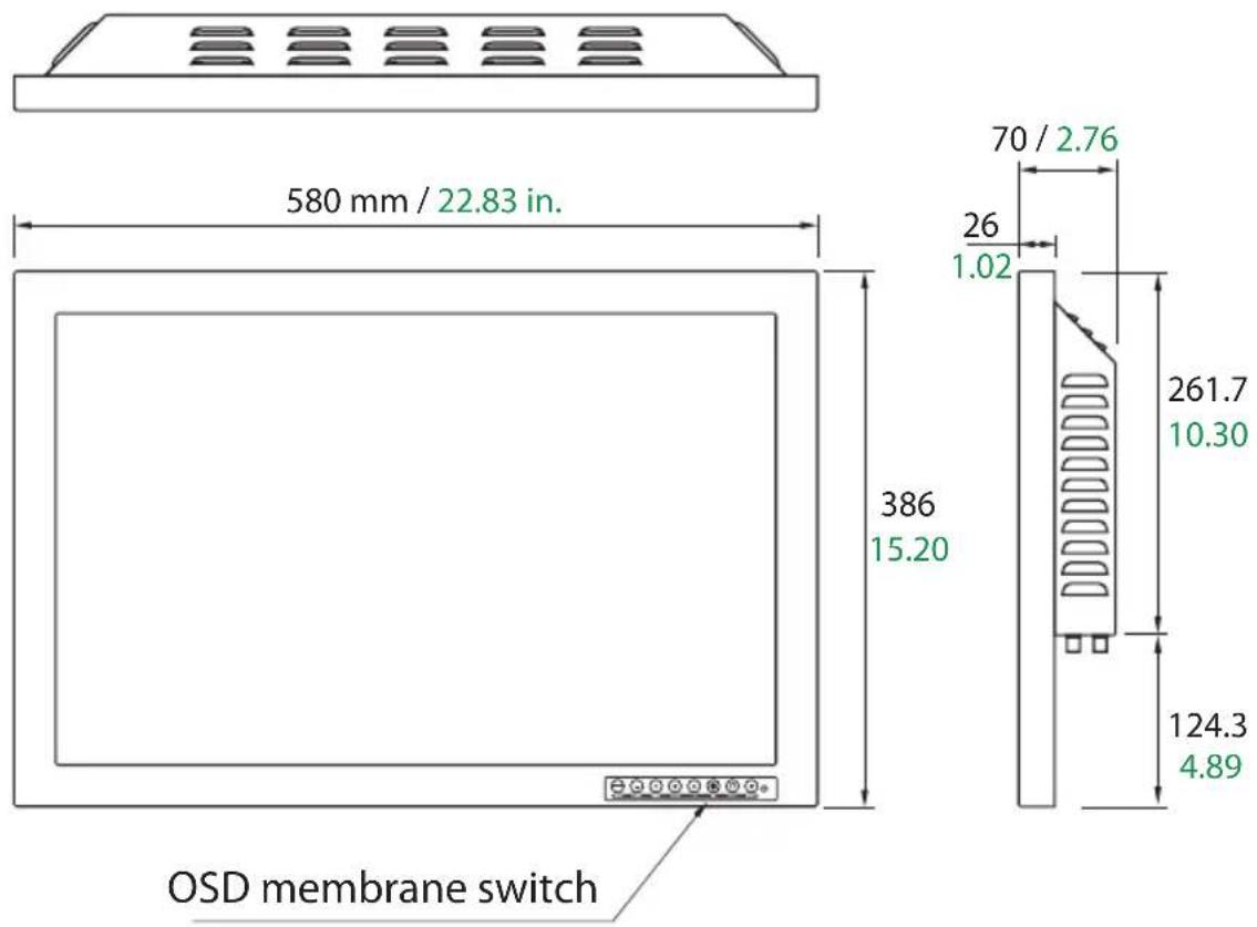
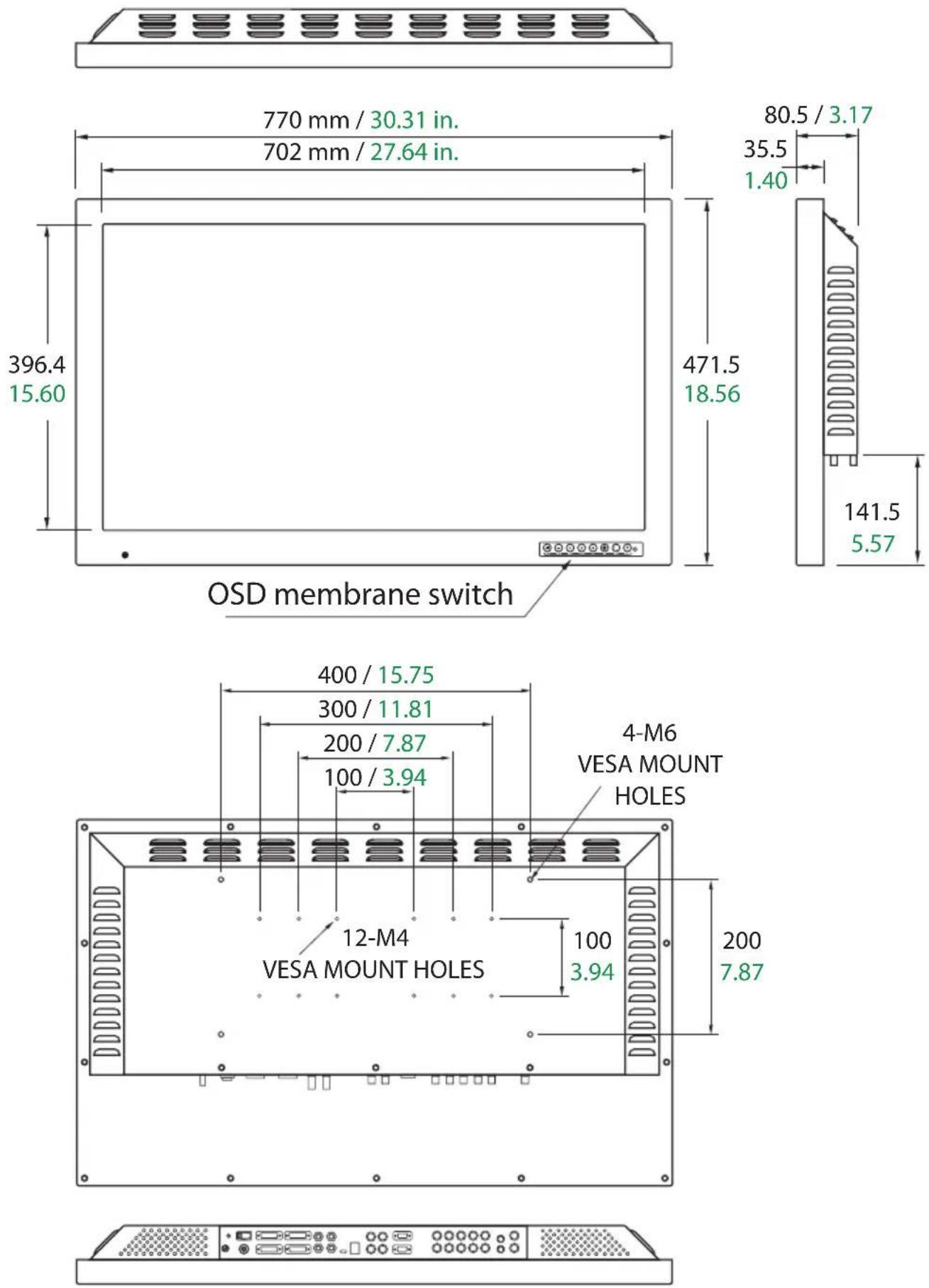
Mechanical Product Drawing
32" FS-L3202D Dimension
Controls
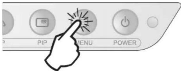
On Screen Display (OSD) Buttons
An 8 button keypad, located in bottom right corner on the front of the display, allows the user to make adjustments to various display parameters using the On Screen Display (OSD) system.
| QUICK ADJUST. Press to decrease the display contrast. No need to enter the OSD main menu.When the OSD menu is activated, press to decrease the adjustment of the selected function. | QUICK ADJUST. Press to decrease the display brightness. No need to enter the OSD main menu.When the OSD menu is activated, press to move the menu selection downward. | Press to enable PIP (picture in Picture) function.Select from:PIPPBP1PBP2 | No Light - Normal, display has power and an active signal.Blinking Light - Standby Mode, no active signal is present.Constant Light - Off Mode, power to the LCD screen has been turned off using the OSD power button, however the display unit is still connected to a power source.Note 1 : Normal and Off Mode behavior of the Power Indicator Light can be changed according to the requirements of the customer. Constant light can be changed to indicate Normal if desired.Note 2 : The main AC power switch on the display's back panel should be in the ON position. The front OSD power button is used to turn on the LCD screen on and off. | |
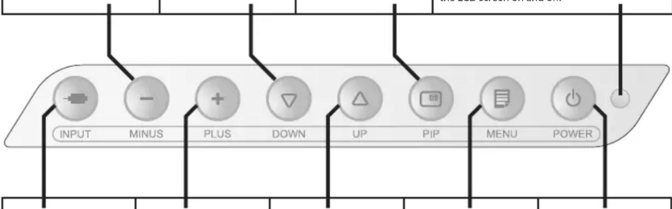 | ||||
| Press to show the input selection menu and to change the display signal source.Input choices: DVI 1, DVI 2, SDI 1, SDI 2*, SOG 1, SOG 2, VGA, RGBS, YPbPr, S-VIDEO, C-VIDEO*FS-L2402D optional. | QUICK ADJUST. Press to increase the display contrast. No need to enter the OSD main menu.When the OSD menu is activated, press to increase the adjustment of the selected function. | QUICK ADJUST. Press to increase the display brightness. No need to enter the OSD main menu.When the OSD menu is activated, press to move the menu selection upward. | Press to activate the OSD menu.When the OSD menu is active, press to exit from the main menu or submenu. | Press to turn power on/off to the display's front LCD screen. |
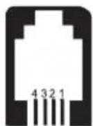
GPIO
There are four pins on the RJ9 GPIO connector. Each pin has a pre programmed function assigned to it. The function is initiated when the pin is grounded.
Pin 1.
Primary and Secondary Swap. Grounding this pin will swap the primary and secondary image.
Pin 2.
PIP, PBP1, PBP2, Single. Continuously grounding this pin causes the position and size choices to cycle.

Pin 3.
Record Indicator. The record indicator is displayed in the top left corner when the pin is ground to pin 4. The indicator will vanish when the contact is opened.

Pin 4.
Connector Ground. This is the common ground location.
Monitor
RJ9
Power Management
This monitor does not adhere to the VESA DPMS standard when no signal is present on the video input.
Status LED sign Power Consumption
FS-L2402D FS-P2603D, FS-P2607D S-L3202D
Normal mode Off <78W (92VA) <70W (83VA) <75W (86VA)
Standby mode Blinking <16W (38VA) <16W (38VA) <16W (38VA)
OSD power off Constant <15W (37VA) <15W (37VA) <15W (37VA)
DC power off Off <0.5W (17VA) <0.5W (17VA) <0.5W (17VA)
On Screen Display (OSD) Menus
FSN display monitors come equipped with a rich set of features for system set-up, image adjustments, and screen layout control. These features are managed through the On Screen Display, or OSD. Some options presented in the OSD are contextual and vary depending on the active input signal. See the Controls section for a complete description of each OSD button.
1. Enter the OSD
To activate the OSD menu, press the MENU button on the front of the display monitor. To close the OSD menu, press the menu button to exit from the main menu or a sub menu.
2. Pick a Main Menu Category
After entering the OSD, use the UP ▲nd Down buttons on the front of the display monitor to navigate to a main menu category.
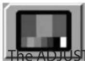

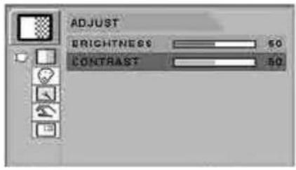
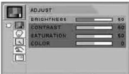
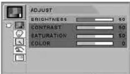
or The ADJUST menu controls brightness, contrast, and more.
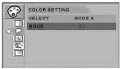
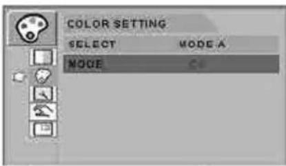
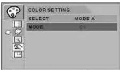
The COLOR SETTING menu controls preset or customized color settings.

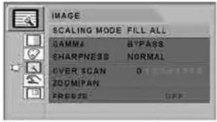
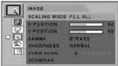
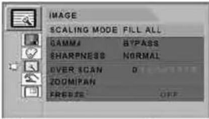
The IMAGE menu controls horizontal / vertical positioning and sharpness.
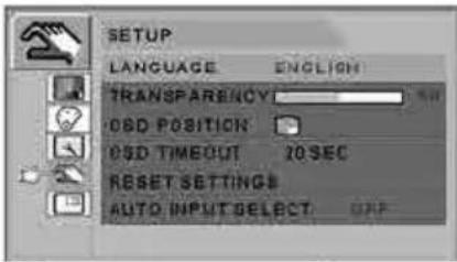
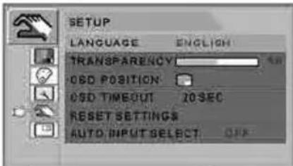
The SETUP menu controls language, OSD behavior, and more.
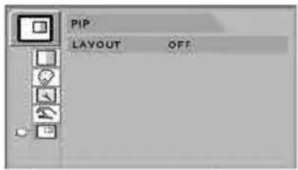
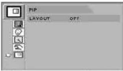
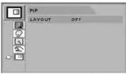
The PIP menu controls picture in picture layouts.
3. Pick a Submenu Category
After using the UP ▲nd Down buttons to navigate to the desired main menu category, press the + button to enter the submenus associated with the selected main menu.
Submenus for the following signal types:
VGA Analog, RGB, Sync On Green (SOG)
After selecting a main menu category, press the + button to enter the associated submenus as shown below. Next, use the UP ▲ and Down ▼ buttons to navigate to the desired submenu, then adjust as needed with the + and - buttons. Select the MENU button to exit from the submenu or main menu.
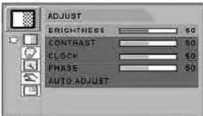 | Submenus under the ADJUST menu1. BRIGHTNESS Increases or decreases the brightness. (Range: 0~100)2. CONTRAST Increases or decreases the contrast. (Range: 0~100)3. CLOCK Increases or decreases the sampling frequency. (Range: 0~100)4. PHASE Increases or decreases the phase level. (Range: 0~100)5. AUTO ADJUST fits to the most appropriate screen on the D-SUB Analog / RGBs signal. |
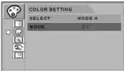 | Submenus under the COLOR SETTING menu1. SELECT Changes the image color setting. (MODE A,B)2. MODE Changes the color mode. (C1, C2, C3, USER)3. RED Red balance. (Only works with USER mode) (Range: 0~255)4. GREEN Green balance. (Only works with USER mode) (Range: 0~255)5. BLUE Blue balance. (Only works with USER mode) (Range: 0~255) |
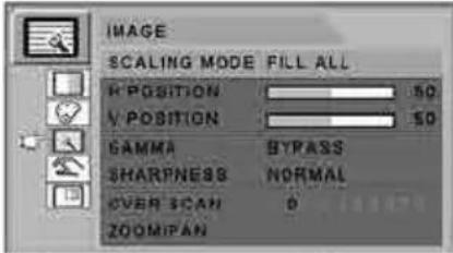 | Submenus under the IMAGE menu1. SCALING MODE Changes the image size. (FILL ASPECT, 1:1,FILL H, FILL V, FILL ALL)2. H POSITION Adjusts the horizontal position of the displayed source image. (Range: 0~100)3. V POSITION Adjusts the vertical position of the displayed source image. (Range: 0~100)4. GAMMA Adjusts GAMMA value. (BYPASS,1.8,2.0,2.2,2.4,2.6,PACS,V0,V1,V2)5. SHARPNESS Sets the sharpness of image. (Softest, Soft, Normal, Sharp, Sharpest)6. OVER SCAN Adjusts the displayed size. (0~8)7. ZOOM / PAN Enlarges the image, moves images left and right.8. FREEZE Keeps the image still. |
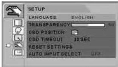 | Submenus under the SETUP menu1. LANGUAGE Changes the OSD language. (9 languages)2. TRANSPARENCY Adjusts the OSD background from white opaque to translucent.3. OSD POSITION Changes the OSD position. (9 Positions)4. OSD TIMEOUT Adjusts the length of time the OSD Menu is present on the screen. (5, 10, 20, 30, 60, 90, 120, 180, 240 seconds)5. RESET SETTINGS Changes all the OSD values to factory default.6. AUTO INPUT SELECT Disables or enables auto source select. (ON: Searches through all possible input sources until an active video source is found.OFF: Video input is manually selected.) |
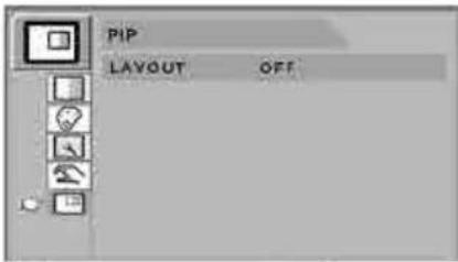 | Submenus under the PIP menu1. LAYOUT Changes the layout. (OFF, PIP, PBP1. PBP2)2. INPUT Changes the secondary source.3. SIZE Changes the PIP size. (Small, Large)4. POSITION Changes the PIP position.5. SWAP Swaps the position of the Primary and Secondary images. |
Submenus for the following signal types:
DVI
After selecting a main menu category, press the + button to enter the associated submenus as shown below. Next, use the UP ▲ and Down ▼ buttons to navigate to the desired submenu, then adjust as needed with the + and - buttons. Select the MENU button to exit from the submenu or main menu.
 | Submenus under the ADJUST menu1. BRIGHTNESS Increases or decrease the brightness. (Range: 0~100)2. CONTRAST Increases or decreases the contrast. (Range: 0~100) |
 | Submenus under the COLOR SETTING menu1. SELECT Changes the image color setting. (MODE A,B)2. MODE Changes the color mode. (C1, C2,C3, USER)3. RED Red balance. (Only works with USER mode) (Range: 0~255)4. GREEN Green balance. (Only works with USER mode) (Range: 0~255)5. BLUE Blue balance. (Only works with USER mode) (Range: 0~255) |
 | Submenus under the IMAGE menu1. SCALING MODE Changes the image size. (FILL ASPECT, 1:1,FILL H, FILL V, FILL ALL)2. GAMMA Adjusts GAMMA value. (BYPASS,1.8,2.0,2.2,2.4,2.6,PACS,V0,V1,V2)3. SHARPNESS Sets the sharpness of image. (Softest, Soft, Normal, Sharp, Sharpest)4. OVER SCAN Adjusts the displayed size. (0~8)5. ZOOM / PAN Enlarges the image, moves images left and right.6. FREEZE Keeps the image still. |
 | Submenus under the SETUP menu1. LANGUAGE Changes the OSD language. (9 language)2. TRANSPARENCY Adjusts the OSD back ground from white opaque to half translucent.3. OSD POSITION Changes the OSD position. (9 Positions)4. OSD TIMEOUT Adjusts time until the OSD menu will disappear after adjusting the menu. (5, 10, 20, 30, 60, 90, 120, 180, 240 seconds)5. RESET SETTINGS Changes all the OSD values to factory default.6. AUTO INPUT SELECT Disables or enables auto source select. (ON: Searches through all possible input sources until an active video source is found.OFF: Video input is manually selected.) |
 | Submenus under the PIP menu1. LAYOUT Changes the layout. (OFF, PIP, PBP1. PBP2)2. INPUT Changes the secondary source.3. SIZE Changes the PIP size. (Small, Large)4. POSITION Changes the PIP position.5. SWAP Swaps the position of the Primary and Secondary images. |
Submenus for the following signal types:
YPbPr
After selecting a main menu category, press the + button to enter the associated submenus as shown below. Next, use the UP ▲ and Down ▼ buttons to navigate to the desired submenu, then adjust as needed with the + and - buttons. Select the MENU button to exit from the submenu or main menu.
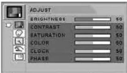 | Submenus under the ADJUST menu1. BRIGHTNESS Increases or decreases the brightness. (Range: 0~100)2. CONTRAST Increases or decreases the contrast. (Range: 0~100)3. SATURATION Changes the tone of color. (Range: 0~100)4. COLOR Changes the richness of color. (Range: green 0~50, red 0~50)5. CLOCK Increases or decreases the sampling frequency. (Range: 0~100)6. PHASE Increases or decreases the Phase level. (Range: 0~100) |
 | Submenus under the COLOR SETTING menu1. SELECT Changes the image color setting. (MODE A,B)2. MODE Changes the color mode. (C1, C2, C3, USER)3. RED Red balance. (Only works with. USER mode) (Range: 0~255)4. GREEN Green balance. (Only works with USER mode) (Range: 0~255)5. BLUE Blue balance. (Only works with USER mode) (Range: 0~255) |
 | Submenus under the IMAGE menu1. SCALING MODE Changes the image size. (FILL ASPECT, 1:1,FILL H, FILL V, FILL ALL)2. H POSITION Adjusts the horizontal position of the displayed source image. (Range: 0~100)3. V POSITION Adjusts the vertical position of the displayed source image. (Range: 0~100)4. GAMMA Adjusts GAMMA value. (BYPASS,1.8,2.0,2.2,2.4,2.6,PACS,V0,V1,V2)5. SHARPNESS Sets the sharpness of image. (Softest, Soft, Normal, Sharp, Sharpest)6. OVER SCAN Adjusts the displayed size. (0~8)7. ZOOM / PAN Enlarges the image, moves images left and right.8. FREEZE Keeps the image still. |
 | Submenus under the SETUP menu1. LANGUAGE Changes the OSD language. (9 language)2. TRANSPARENCY Adjusts the OSD back ground from white opaque to half translucent.3. OSD POSITION Changes the OSD position. (9 positions)4. OSD TIMEOUT Adjusts time until the OSD menu will disappear after adjusting the menu. (5, 10, 20, 30, 60, 90, 120, 180, 240 seconds)5. RESET SETTINGS Changes all the OSD values to factory default.6. AUTO INPUT SELECT Disables or enables auto source select. (ON: Searches through all possible input sources until an active video source is found.OFF: Video input is manually selected.) |
 | Submenus under the PIP menu1. LAYOUT Changes the layout. (OFF, PIP, PBP1. PBP2).2. INPUT Changes the secondary source.3. SIZE Changes the PIP size. (Small, Large)4. POSITION Changes the PIP position.5. SWAP Swaps the position of the Primary and Secondary images. |
Submenus for the following signal types:
S-VIDEO, C-VIDEO
After selecting a main menu category, press the + button to enter the associated submenus as shown below. Next, use the UP ▲ and Down ▼ buttons to navigate to the desired submenu, then adjust as needed with the + and - buttons. Select the MENU button to exit from the submenu or main menu.
 | Submenus under the ADJUST menu1. BRIGHTNESS Increases or decreases the brightness. (Range: 0~100)2. CONTRAST Increases or decreases the contrast. (Range: 0~100)3. SATURATION Changes the tone of color. (Range: 0~100)4. COLOR Changes the richness of color. (Range: green 0~50, red 0~50) |
 | Submenus under the COLOR SETTING menu1. SELECT Changes the image color setting. (MODE A,B)2. MODE Changes the color mode. (C1, C2, C3, USER)3. RED Red balance. (Only works with USER mode) (Range: 0~255)4. GREEN Green balance. (Only works with USER mode) (Range: 0~255)5. BLUE Blue balance. (Only works with USER mode) (Range: 0~255) |
 | Submenus under the IMAGE menu1. SCALING MODE Changes the image size. (FILL ASPECT, 1:1,FILL H, FILL V, FILL ALL)2. H POSITION Adjusts the horizontal position of the displayed source image. (Range: 0~100)3. V POSITION Adjusts the vertical position of the displayed source image. (Range: 0~100)4. GAMMA Adjusts GAMMA value. (BYPASS,1.8,2.0,2.2,2.4,2.6,PACS,V0,V1,V2)5. SHARPNESS Sets the sharpness of image. (Softest, Soft, Normal, Sharp, Sharpest)6. OVER SCAN Adjusts the displayed size. (0~8)7. ZOOM / PAN Enlarges the image, moves images left and right.8. FREEZE Keeps the image still. |
 | Submenus under the SETUP menu1. LANGUAGE Changes the OSD language. (9 language)2. TRANSPARENCY Adjust the OSD back ground from white opaque to half translucent.3. OSD POSITION Changes the OSD position. (9 Positions)4. OSD TIMEOUT Adjusts time until the OSD menu will disappear after adjusting the menu. (5, 10, 20, 30, 60, 90, 120, 180, 240 seconds)5. RESET SETTINGS Changes all the OSD values to factory default.6. AUTO INPUT SELECT Disables or enables auto source select. (ON: Searches through all possible input sources until an active video source is found.OFF: Video input is manually selected.) |
 | Submenus under the PIP menu1. LAYOUT Changes the layout. (OFF, PIP, PBP1. PBP2)2. INPUT Changes the secondary source.3. SIZE Changes the PIP size. (Small, Large)4. POSITION Changes the PIP position.5. SWAP Swaps the position of the Primary and Secondary images. |
Submenus for the following signal types:
SDI
After selecting a main menu category, press the + button to enter the associated submenus as shown below. Next, use the UP ▲ and Down ▼ buttons to navigate to the desired submenu, then adjust as needed with the + and - buttons. Select the MENU button to exit from the submenu or main menu.
 | Submenus under the ADJUST menu1. BRIGHTNESS Increases or decreases the brightness. (Range: 0~100)2. CONTRAST Increases or decreases the contrast. (Range: 0~100)3. SATURATION Changes the tone of color. (Range: 0~100)4. COLOR Changes the richness of color. (Range: green 0~50, red 0~50) |
 | Submenus under the COLOR SETTING menu1. SELECT Changes the image color setting. (MODE A,B)2. MODE Changes the color mode (C1, C2, C3, USER)3. RED Red balance. (Only works with USER mode) (Range: 0~255)4. GREEN Green balance. (Only works with USER mode) (Range: 0~255)5. BLUE Blue balance. (Only works with USER mode) (Range: 0~255) |
 | Submenus under the IMAGE menu1. SCALING MODE Changes the image size. (FILL ASPECT, 1:1,FILL H, FILL V, FILL ALL)2. GAMMA Adjusts GAMMA value. (BYPASS,1.8,2.0,2.2,2.4,2.6,PACS,V0,V1,V2)3. SHARPNESS Sets the sharpness of image. (Softest, Soft, Normal, Sharp, Sharpest)4. OVER SCAN Adjusts the displayed size. (0~8)5. ZOOM / PAN Enlarges the image, moves images left and right.6. FREEZE Keeps the image still. |
 | Submenus under the SETUP menu1. LANGUAGE Changes the OSD language. (9 language)2. TRANSPARENCY Adjusts the OSD back ground from white opaque to half translucent.3. OSD POSITION Changes the OSD position. (9 Positions)4. OSD TIMEOUT Adjusts time until the OSD menu will disappear after adjusting the menu. (5, 10, 20, 30, 60, 90, 120, 180, 240 seconds)5. RESET SETTINGS Changes all the OSD values to factory default.6. AUTO INPUT SELECT Disables or enables auto source select. (ON: Searches through all possible input sources until an active video source is found.OFF: Video input is manually selected.) |
 | Submenus under the PIP menu1. LAYOUT Changes the layout. (OFF, PIP, PBP1. PBP2)2. INPUT Changes the secondary source.3. SIZE Changes the PIP size. (Small, Large)4. POSITION Changes the PIP position.5. SWAP Swaps the position of the Primary and Secondary images. |
3D Control (FS-P2607D)
FS-P2607D is equipped to display three-dimensional video images. This model has an additional main On Screen Display (OSD) menu category. Following are instructions for adjusting the 3D features of FS-P2607D.
1. Enter the OSD
To activate the OSD menu, press the MENU button on the front of the display monitor. To close the OSD menu, press the menu button to exit from the main menu or a sub menu.
2. Choose the 3D CONTROL Category
After entering the OSD, use the UP ▲nd Down buttons on the front of the display monitor to navigate to the 3D CONTROL main menu category.
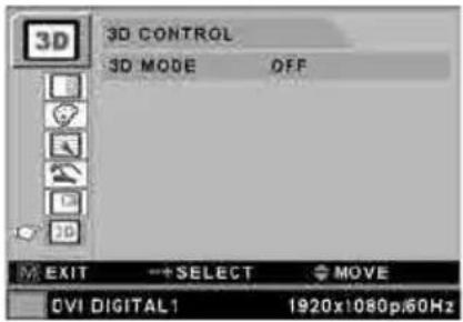
The 3D CONTROL menu is used to adjust 3D settings on FS-P2607D.
After navigating to the 3D CONTROL main menu category, press the + button to enter the 3D CONTROL submenu.
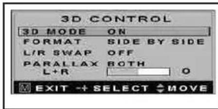
Submenus under the 3D CONTROL menu
- 3D MODE ON/OFF Turns the 3D mode on or off.
- FORMAT Changes the format of the 3D image being displayed.
- L/R SWAP Swaps the left and right images.
- PARALLAX Selects the left, right, or both images for changing their parallax setting. The status bar below parallax shows the adjustment to L, R, or Both.
| Submenu Function/Description | |
| 3D FORMAT | Changes the 3D format. 3D is only supported using DVI or SDI input sources.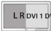 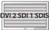     Side by Side Line by Line Dual Input Images can be switched using L/R swap function Top / BottomDVI 2 and SDI 1, 2 support Top/Bottom Side by Side Line by Line Dual Input Images can be switched using L/R swap function Top / BottomDVI 2 and SDI 1, 2 support Top/Bottom |
| PARALLAX | Changes the point of view on 3D. Left or Right can be adjusted independently, or both can be adjusted together.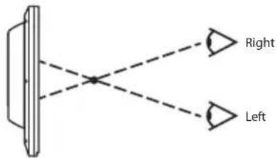 |
On Screen Display (OSD) System Overview
Submenu Descriptions
| Submenu Function/Description | |||
| BRIGHTNESS | Quick Adjust Method: Press the UP ▲ or DOWN ▼ buttons.Or, select BRIGHTNESS submenu and adjust with the PLUS + and MINUS -. Setting the brightness too high or too low will decrease the amount of visible gray scales. | ||
| CONTRAST | Quick Adjust Method: Press the PLUS + or MINUS - buttons.Or, select CONTRAST submenu and adjust with the PLUS + and MINUS -. Setting the contrast too high or too low will cause loss of some gray scales. | ||
| CLOCK | Do not adjust. This setting will adjust automatically after auto adjustment. When frequency value is wrong, the horizontal image may display incorrectly or picture noise may be present. | ||
| PHASE | Do not adjust . This setting will adjust automatically after auto adjustment. When frequency value is wrong, picture noise may be present. | ||
| AUTO ADJUST Fits to the most appropriate screen on the D-SUB Analog signal. | |||
| SHARPNESS Adjusts the sharpness of a video image. | |||
| SATURATION Changes the color tone. | |||
| COLOR Changes the r chness of color. | |||
| COLOR MODE C1 | Custom color setting mode 1. (C1 in MODE-A is the default color setting (REC709 with D65)) | ||
| COLOR MODE C2 Customer color setting mode 2 | |||
| COLOR MODE C3 Customer color setting mode 3 | |||
| COLOR MODE USER Bypasses default color settings and allows for custom user adjustable color settings. | |||
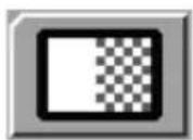
| SCALING MODE Results when the image has an aspect ratio > 16:9 | |||
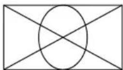 FILL ALL FILL ASPECT, FILL H 1:1 FILL V FILL ALL FILL ASPECT, FILL H 1:1 FILL V |  |  | 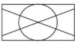 |
| SCALING MODE Results when the image has an aspect ratio < 16:9 | |||
 FILL ALL FILL ALL |  FILL ASPECT, FILL V FILL ASPECT, FILL V |  1:1 FILL H 1:1 FILL H | 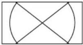 |
On Screen Display (OSD) System Overview (continued)
Submenu Descriptions
| Submenu Function/Description | |||||
| H POSITION |  | Adjusts the horizontal position of the image. This setting will return to the default state when executing AUTO ADJUST or RESET SETTINGS. | |||
| V POSITION |  | Adjusts the vertical position of the image. This setting will return to the default state when executing AUTO ADJUST or RESET SETTINGS. | |||
| GAMMA | Adjusts the gamma curve of a video image. Note: BYPASS depends on panel gamma value, please refer to the panel specification. | ||||
| 1.8 2.0 2.2 2.4 2.6 PACS V0,V1,V2 | |||||
 |  |  | 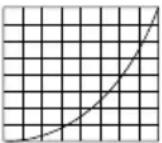 | 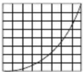 | 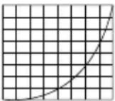 |
| SHARPNESS | Adjusts the sharpness of a video image. | ||||
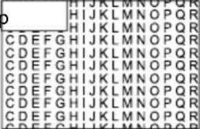
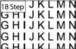
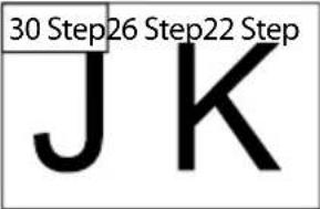
| OVER SCAN | Enables an 8-step, 10% maximum, over scan of original input image.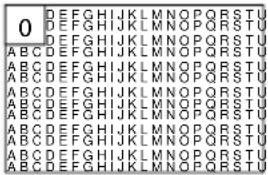         | ||||
On Screen Display (OSD) System Overview (continued)
Submenu Descriptions
| Submenu Function/Description | |||
| ZOOM / PAN Controls image ZOOM in/out. | |||
 |  |  |  |
 |  |  |  |
Controls the image PAN left/right, up/down. The maximum ZOOM size is ten times as large as the original. | |||
| FREEZE Freezes the main image. Does not freeze secondary image in PIP mode. | |||
| LANGUAGE | Changes the OSD to one of 9 languages: ENGLISH, GERMAN, FRENCH, SPANISH, ITALIAN, JAPANESE, CHINESE, TURKISH, KOREAN | ||
| OSD TRANSPARENCY | Adjusts the transparency of the OSD menu box.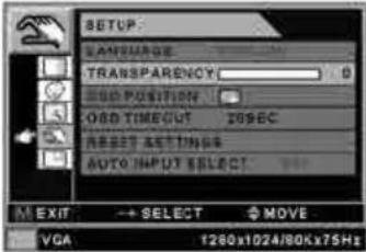 [Transparent] [Transparent] 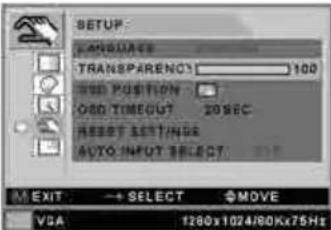 | ||
OSD POSITION Changes the on-screen position of the OSD menu box to 1 of 9 locations.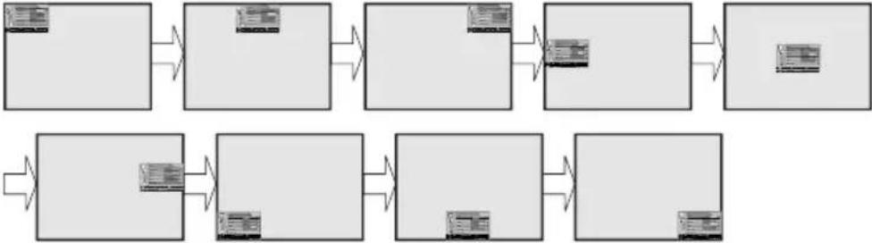 | |||
On Screen Display (OSD) System Overview (continued)
Submenu Descriptions
| Submenu | Function/Description | |
| OSD TIMEOUT | Adjusts the time until the OSD menu will disappear after making adjustments. | |
| RESET SETTINGS | Resets the unit to its original status when it left the factory. | |
| AUTO INPUT SELECT | When set to ON, the monitor will automatically search for connected input sources.Does not affect the sub window when in PIP mode. | |
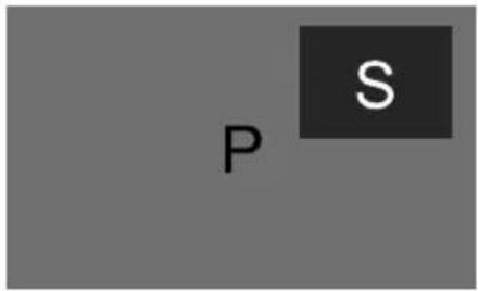
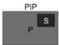
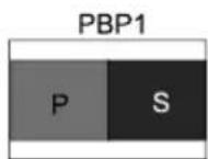
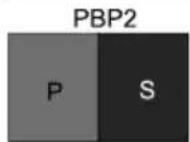
| PIP LAYOUT | Changes the sub window layout: OFF, PIP, PBP1, PBP2. Picture in Picture (PIP)- Supported scaling modes: FILL ASPECT, FILL ALL,FILL H, FILL V.- FILL ASPECT is the default scaling mode. Picture in Picture (PIP)- Supported scaling modes: FILL ASPECT, FILL ALL,FILL H, FILL V.- FILL ASPECT is the default scaling mode.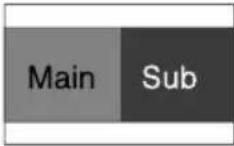 Picture by Picture 1 (PBP1)- Supported scaling modes: FILL ASPECT, FILL ALL.- FILL ASPECT is the default scaling mode.- Canvas aspect ratio is 4:3. Picture by Picture 1 (PBP1)- Supported scaling modes: FILL ASPECT, FILL ALL.- FILL ASPECT is the default scaling mode.- Canvas aspect ratio is 4:3. Picture by Picture 2 (PBP2)- Supported scaling modes: FILL ASPECT, FILL ALL.- FILL ALL is the default scaling mode.- Canvas aspect ratio is half window. Picture by Picture 2 (PBP2)- Supported scaling modes: FILL ASPECT, FILL ALL.- FILL ALL is the default scaling mode.- Canvas aspect ratio is half window. | |
| PIP INPUT | Selects the PIP source input. The following table shows PIP matching options withthe main and sub window. | |
| DVI 1 DVI 2 VGA SOG 1 SOG 2 SDI 1 SDI 2*YPbPr/RGBS C/S-Video | ||
| DVI 1 XO O O O O O O O | ||
| DVI 2 O X O O O O O O | ||
| VGA O O X O O O O O | ||
| SOG 1 O O O X O O O O | ||
| SOG 2 O O O X O O O | ||
| SDI 1 O O O O X O O | ||
| SDI 2* O O O O O X O O | ||
| YPbPr/RGBS O O O O O O X O | ||
| C/S-Video O O O O O O O X | ||
 | ||
| PIP SIZE | Changes the size of the sub window when using PIP mode.   Small - 25% of panel size Large - 33% of panel size CAUTION : DO notchange input sourceaspect ratio. The PIPaspect ratio dependson input timing. Small - 25% of panel size Large - 33% of panel size CAUTION : DO notchange input sourceaspect ratio. The PIPaspect ratio dependson input timing. | |
| PIP POSITION | Changes the on-screen position of the PIP sub window to 1 of 9 locations.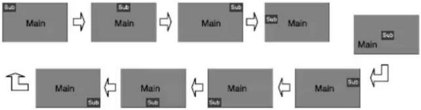 | |
On Screen Display (OSD) System Overview (continued)
Submenu Descriptions
| Submenu Function/Description | |
| PIP SWAP | Swap main window and sub window contents in PIP,PBP1,PBP2.Picture in picture (PIP):Picture by Picture 1 (PBP1): 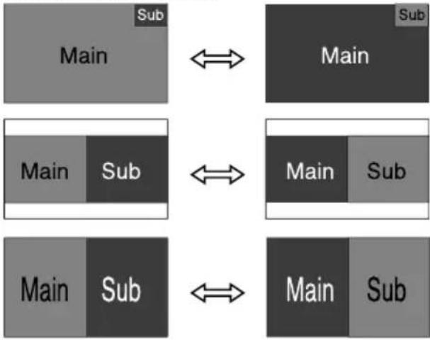 Picture by Picture 2 (PBP2)*: Picture by Picture 2 (PBP2)*: |
* Scaling mode must be set to "FILL ALL" in the OSD's IMAGE menu for PBP2 to fill the screen.
Remote Control (FS-L3202D only)
| Key Name Description | |
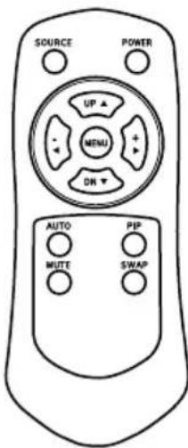 | Power Soft power. Turns the monitor ON/OFF. |
| Source Changes the display signal source. | |
| Menu With OSD deactivated, Activates the OSD menu. With OSD activated, exits from main menu or sub menu. | |
| UP (▲) With OSD deactivated, hot key for brightness control. Increases the brightness. With OSD activated, moves the OSD cursor upward. | |
| Down (▼) With OSD deactivated, hot key for brightness control. Decreases the brightness. With OSD activated, moves the OSD cursor downward. | |
| Plus (+) With OSD deactivated, hot key for contrast control. Increases the contrast. With OSD activated, enters the sub menu and increases the adjustment of the selected function. | |
| Minus (-) With OSD deactivated, hot key for contrast control. Decreases the contrast. With OSD activated, decreases the adjustment of the selected function. | |
| AUTO Fit a D-SUB analog signal to the most appropriate screen. | |
| PIP Enables PIP (Picture in Picture) function. Select PIP,PBP1,PBP2. | |
| MUTE N/A | |
| SWAP Swaps the position of the primary and secondary images. |
Standard Signal Table
PC Supported Mode
| Resolution | Horizontal Frequency (KHz) | Vertical Frequency (Hz) | Clock Frequency (MHz) |
| 640 x 350 @70Hz 31.469 70.087 25.175 | |||
| 640 x 480 @60Hz 31.469 59.940 25.175 | |||
| 640 x 480 @72Hz 37.861 72.809 31.500 | |||
| 640 x 480 @75Hz 37.500 75.000 31.500 | |||
| 640 x 480 @85Hz 43.269 85.008 36.000 | |||
| 800 x 600 @56Hz 35.156 56.250 36.000 | |||
| 800 x 600 @60Hz 37.879 60.317 40.000 | |||
| 800 x 600 @72Hz 48.077 72.188 50.000 | |||
| 800 x 600 @75Hz 46.875 75.000 49.500 | |||
| 800 x 600 @85Hz 53.674 85.061 56.250 | |||
| 1024 x 768 @60Hz 48.363 50.004 65.000 | |||
| 1024 x 768 @70Hz 56.476 70.069 75.000 | |||
| 1024 x 768 @75Hz 60.023 75.029 78.750 | |||
| 1024 x 768 @85Hz 68.677 84.997 94.500 | |||
| 1152 x 864 @60Hz 54.348 50.053 80.000 | |||
| 1152 x 864 @75Hz 67.500 75.000 108.000 | |||
| 1280 x 720 @60Hz 45.000 50.000 74.250 | |||
| 1280 x 960 @60Hz 60.000 50.000 108.000 | |||
| 1280 x 960 @85Hz 85.938 85.002 148.500 | |||
| 1280 x 1024 @60Hz 63.974 60.013 108.500 | |||
| 1280 x 1024 @75Hz 79.976 75.025 135.000 | |||
| 1280 x 1024 @85Hz 91.146 85.024 157.500 | |||
| 1600 x 1200 @60Hz (**) 74.077 59.981 130.375 | |||
| 1600 x 1200 @60Hz 75.000 60.000 162.000 | |||
| 1920 x 1080 @60Hz 67.500 60.000 148.500 | |||
| 1920 x 1200 @ 60Hz 74.038 59.950 153.999 (*) |
(*) FS-L2402D only (**) Preferred Timing for 1600 x 1200 @60Hz input
SDI Video Format
| Output Signal Description | |
| SMPTE-424M 1080p (3G) | |
| SMPTE-292M 720p , 1080i (HD) | |
| SMPTE-259M 480i , 576i (SD) |
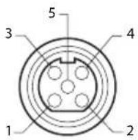
Signal Connector Pin Assignments
DC Input
| Pin No. | Assignment |
| 1 | Ground |
| 2 | Ground |
| 3 | +24V (DC) |
| 4 | F.G. (ground) |
| 5 | +24V (DC) |
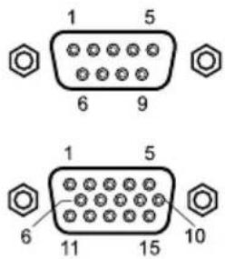
VGA & Debug Port Interface Connector
| Pin No. | Assignment Pin No. Assignment | ||
| 1 RED 1 - | |||
| 2 GREEN 2 TXD | |||
| 3 BLUE 3 RXD | |||
| 4 GND 4 - | |||
| 5 GND 5 GND | |||
| 6 | GND-RED 6 - | ||
| 7 | GND-GREEN | 7 - | |
| 8 | GND-BLUE | 8 RS_VDD | |
| 9 | DDC 5V / Check Cable | 9 - | |
| 10 | GND-SYNC | ||
| 11 | GND | ||
| 12 | DDC DATA | ||
| 13 | HORIZONTAL SYNC | ||
| 14 | VERITICAL SYNC | ||
| 15 | DDC CLOCK | ||
Signal Connector Pin Assignments
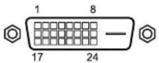
DVI Input / output interface connector
| Pin No. | Assignment Pin No. | Assignment | |
| 1 | T.M.D.S. Data 2- 13 | T.M.D.S. Data 3+ | |
| 2 | T.M.D.S. Data 2+ 14 +5V Power | ||
| 3 | T.M.D.S. Data 2/4 Shield 15 GND | ||
| 4 | T.M.D.S. Data 4- 16 Hot Plug Detect | ||
| 5 | T.M.D.S. Data 4+ 17 T.M.D.S.Data 0- | ||
| 6 | DDC Clock 18 T.M.D.S. Data 0+ | ||
| 7 | DDC Data 19 T.M.D.S. Data 0/5 Shield | ||
| 8 | No Connection 20 T.M.D.S. Data 5- | ||
| 9 | T.M.D.S. Data 1- 21 T.M.D.S. Data 5+ | ||
| 10 | T.M.D.S. Data 1+ 22 | T.M.D.S. Clock Shield | |
| 11 | T.M.D.S. Data 1/3 Shield 23 T.M. | D.S. Clock+ | |
| 12 | T.M.D.S. Data 3- 24 | T.M.D.S. Clock- | |
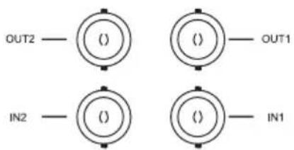
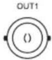
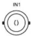
SOG input / output interface connector
| Pin No. | Description Pin No. | Description |
| IN1 SOG SIGNAL IN IN2 SOG SIGNAL IN | ||
| OUT1 | SOG SIGNAL OUT | OUT2 |
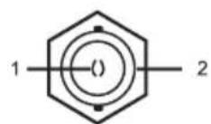
SDI interface connector
| CN8Pin No. | Description |
| 1 | SDI input |
| 2 | GND |
Signal Connector Pin Assignments (continued)
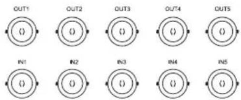
Component (RGBS, YPbPr) input / output interface connector
| Pin No. | Description Pin No. | Description | |
| IN1 | R/Pr IN OUT1 | R/Pr OUT | |
| IN2 | G/Y IN OUT2 | G/Y OUT | |
| IN3 | B/Pb IN OUT3 | B/Pb OUT | |
| IN4 | HS/CS IN OUT4 | HS/CS OUT | |
| IN5 | VS IN OUT5 | VS OUT |
C-Video input / output interface connector
| Pin No. | Description Pin No. | Description |
| IN1 | C-Video IN | OUT1 C-Video OUT |
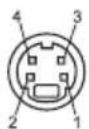
S-Video input / output interface connector
| Description | Description | ||
| IN | Y/C IN | OUT | Y/C OUT |
| Pin No. | Description Pin No. | Description | |
| 1 | Y GND | 2 | C GND |
| 3 | Y SIGNAL | 4 | C SIGNAL |
GPIO
| Pin No. | Assignment |
| 1 | P,S Swap |
| 2 | PIP,PBP1,PBP2 Select |
| 3 | Record Indicator |
| 4 | Ground |

1234
Specification
FS-L2402D
| Item Description | ||
| Optical Characteristics | Type 24" LED backlit LCD | |
| Screen Size 24 inch(16:10) | ||
| Maximum Resolution 1920X 1200 | ||
| Pixel Pitch 0.27 x 0.27 | ||
| Display Colors 16.7M colors | ||
| Contrast Ratio (Typ.) 1000:1 | ||
| Viewing Angle 89° / 89° / 89° | ||
| Response Time 14 msec (gray to gray) | ||
| Luminance (Typical) 600 cd/m ^2 | ||
| Front Filter Acrylic Double side Anti-Reflection coating | ||
| Resolution Signal Input | VGA~1200p | |
| Power Consumption | Maximum | Max 78W (92VA max) |
| Standby Mode | Max 16W (38VA max) | |
| Control Key | Front Side | INPUT, -, +, ▲, ▼, PIP, MENU, POWER |
| Input Signal | Video | 2 x DVI-D, 1 x SDI(SD/HD/3G)(2 x SDI optional),2 x SOG, 1 x VGA, 1 x C-VIDEO, 1 x S-VIDEO1 x Component (RGBS,YPbPr) |
| Output Signal | Video | 2 x DVI-D, 1 x SDI(SD/HD/3G) (2 x SDI optional),2 x SOG, 1 x C-VIDEO, 1 x S-VIDEO1 x Component (RGBS,YPbPr) |
| Power Supply | AC/DC Adaptor (AC 100-240V~, DC 24V 6.25A) | |
| Mounting Hole | VESA standard (100mm X 100mm) | |
| Dimensions | Size and Weight | 580(W) x 386(H) x 70(D) (mm)7.5 Kg -Without stand22.835(W) x 15.197(H) x 2.756(D) (inch)16.53 lbs - Without stand |
Specification
FS-P2603D, FS-P2607D (3D)
| Item Description | ||
| Optical Characteristics | Type 26" LED backlit LCD | |
| Screen Size 26 inch(16:9) | ||
| Maximum Resolution 1920X 1080 @ 60Hz | ||
| Pixel Pitch 0.3(H) mm X 0.3(V) mm | ||
| Display Colors 1.07 Billion colors | ||
| Contrast Ratio (Typ.) 1400:1 | ||
| Viewing Angle 89° / 89° / 89° / 89° | ||
| Response Time 18 msec (rising and falling) | ||
| Luminance (Typical) 450 cd/m ^2 | ||
| Front Filter Glass Double side Anti-Reflection coating | ||
| 3D Feature (FS-P2607D) | Passive 3D with Xpol® polarization filter | |
| Resolution | Signal Input | VGA~1080p |
| Power Consumption | Maximum | Max 70W (83VA max) |
| Standby Mode | Max 16W (38VA max) | |
| Control Key | Front Side | INPUT, -, +, ▲, ▼, PIP, MENU, POWER |
| Input Signal | Video | 2 x DVI-D, 2 x SDI(SD/HD/3G), 2 x SOG1 x VGA, 1 x C-VIDEO, 1 x S-VIDEO1 x Component (RGBS,YPbPr) |
| Output Signal | Video | 2 x DVI-D, 2 x SDI(SD/HD/3G), 2 x SOG1 x C-VIDEO, 1 x S-VIDEO1 x Component (RGBS,YPbPr) |
| Power Supply | AC/DC Adaptor (AC 100-240V~, DC 24V 6.25A) | |
| Mounting Hole | VESA standard (100mm X 100mm) | |
| Dimensions | Size and Weight | 668(W) x 421(H) x 88.8(D) (mm)8.2 Kg - (FS-P2603D without stand)8.3 Kg - (FS-P2607D without stand)26.299(W) x 16.574(H) x 3.496(D) (inch)18 lbs - (FS-P2603D without stand)18.3 lbs - (FS-P2607D without stand) |
Specification
FS-L3202D
| Item Description | ||
| Optical Characteristics | Type 32" LED backlit LCD | |
| Screen Size 32 inch(16:9) | ||
| Maximum Resolution 1920X 1080 @ 60Hz | ||
| Pixel Pitch 0.36375 x 0.36375 | ||
| Display Colors 16.7M colors | ||
| Contrast Ratio (Typ.) 1300:1 | ||
| Viewing Angle 89° / 89° / 89° | ||
| Response Time 25 msec (Gray to Gray) | ||
| Luminance (Typical) 500 cd/m ^2 | ||
| Front Filter Glass Double side Anti-Reflection coating | ||
| Resolution Signal Input | VGA~1080p | |
| Power Consumption | Maximum | Max 75W (86VA max) |
| Standby Mode | Max 16W (38VA max) | |
| Control Key | Front Side | INPUT, -, +, ▲, ▼, PIP, MENU, POWER |
| Input Signal | Video | 2 x DVI-D, 2 x SDI(SD/HD/3G), 2 x SOG1 x VGA, 1 x C-VIDEO, 1 x S-VIDEO1 x Component (RGBS,YPbPr) |
| Output Signal | Video | 2 x DVI-D, 2 x SDI(SD/HD/3G), 2 x SOG1 x C-VIDEO, 1 x S-VIDEO1 x Component (RGBS,YPbPr) |
| Power Supply | AC/DC Adaptor (AC 100-240V~, DC 24V 6.25A) | |
| Mounting Hole | VESA standard (100mm X 100mm, 200mm x 100mm, 400mm x 200mm) | |
| Dimensions | Size and Weight | 770(W) x 471.5(H) x 80.5(D) (mm)12.8 Kg -Without stand30.31(W) x 18.56(H) x 3.16(D) (inch)28.1 lbs - Without stand |
Note: CCC certification is not available for this model.
Cleaning Instructions
Precautions
Before cleaning, switch the display in stand-by position to prevent the control touch panel from being activated inadvertently by sweeping over the front filter. In stand-by position the touch panel cannot be activated by just sweeping over them. To switch the display on again, you must press the stand-by key again.
Take care not to damage or scratch the front filter or LCD panel.
- Be careful with rings or other jewelry that can touch the front filter.
- Do not apply pressure on the front filter or LCD panel.
- Do not apply or spray liquid directly to the front filter, panel or cabinet as excess liquid may cause damage to internal electronics. Instead, apply the liquid to the cleaning cloth.
• Follow your hospital protocol for the handling of blood and body fluids.
• The display is not disinfected or packed in sterile environment. - Follow your hospital protocol in case the display needs to be disinfected prior to installation.
Front Filter
Proceed as follows:
- Remove dust with a dry, lint-free, non-abrasive soft cotton cloth.
- Remove fingerprints or grease using a lint-free, non-abrasive soft cotton cloth that is lightly moistened with plain water or a mild commercial glass cleaning product suited for coated glass surfaces.
- Gently wipe dry with a dry cloth.
The following products are tested and approved:
• Misty Clear Lemon 10 Disinfectant
- Bohle glass cleaner
• Zep Heavy-duty glass & all surface cleaner
- Klear Screen
• Screen TFT (Kontakt Chemie)
• Incidin Foam (Ecolab)
- Microzid
- Mild detergent
• Isopropyl alcohol with concentration < 5%
- Household bleach (generic sodium hypochlorite, solutions of 5.25% sodium hypochlorite diluted with water between 1:10 and 1:100)
Cleaning Instructions (continued)
Precautions
Do NOT use on front filter:
• Alcohol/solvents at higher concentration > 5%
• Strong alkalis, strong solvents
- Acid
• Detergents with fluoride
• Detergents with ammonia
• Detergents with abrasives
- Steel wool
- Sponge with abrasives
- Steel blades
- Cloth with steel thread
Cabinet
Proceed as follows:
- Clean the cabinet using a soft cotton cloth, lightly moistened with a recognized cleaning product for medical equipment.
- Repeat with water only.
• Wipe dry with a dry cloth.
The cabinet has been tested for resistance to the following products:
• Virex Ready-to-use Disinfectant Cleaner
• Misty Clear Lemon 10 Disinfectant
• Misty Multi-Purpose Disinfectant Cleaner
• Misty Multi-Purpose Disinfectant Cleaner II
• Zep Heavy-duty glass & all surface cleaner
- Klear Screen
• Screen TFT (Kontakt Chemie)
• Incidin Foam (Ecolab)
- Microzid
- Mild detergent
• Isopropyl alcohol with concentration < 5%
• Precise Hospital Foam Cleaner Disinfectant
- Household bleach (generic sodium hypochlorite, solutions of 5.25% sodium hypochlorite diluted with water between 1:10 and 1:100)
Notes
Thank you for choosing our product.
Service
Please contact our customer service if you need any information or help with our products.
Warranty
One year, parts and labor.
EC Representative
FORESEESON GmbH
Industriestrasse 38a, 63150 Heusenstamm, Germany
Tel. +49(0)6104-643980
FORESEESON UK Ltd.
Unit 71, Barwell Business Park
Leatherhead Road, Chessington, Surrey
KT9 2NY, UK
Tel. +44-(0)208-546-1047
FORESEESON KOREA
404B, Pangyoinnovalley B, 253 Pangyo-ro, Bundang-gu,
Seongnam-si, Gyeonggi-do, Korea, 463-400
Room 307, 3F No. 56, 461 Hongcao Road
Caohejing Development District
Xuhui, Shanghai 200233
Tel: 86-21-6113-4188

FSN™
FORESEESON CUSTOM DISPLAYS, INC.
2210 E. Winston Road, Anaheim, CA 92806 USA
Tel. 1-714-300-0540 Fax. 1-714-300-0546
Specifications are subject to change with or without notice.


FS-L2402D
FS-P2603D
www.fsnmed.com

Medical Technologies


- Medical Display
- User's Guide
- Table of Contents
- Overview
- FS-L2402D FS-P2603D FS-P2607D (3D) FS-L3202D
- Symbol Definitions
- Language: English
- Safety Instructions
- On Safety
- On installation
- Environmental Conditions for Operation and Storage
- Intended Use
- Cautions
- Caution
- Underwriters Laboratories (UL) Classification:
- UL safety Compliance:
- EEC Safety Compliance:
- Recycling
- Cleaning Instructions
- Servicing
- Accessories
- Classification
- FCC Information
- NOTICES TO USER
- FCC WARNING
- PRODUCT LIFETIME
- Recommended separation distances between portable and mobile RF communications equipment and this medical LCD monitor.
- Parts
- Connectors
- Mechanical Product Drawing
- Controls
- On Screen Display (OSD) Buttons
- GPIO
- Pin 1.
- Pin 2.
- Pin 3.
- Pin 4.
- Power Management
- On Screen Display (OSD) Menus
- Enter the OSD
- Pick a Main Menu Category
- Pick a Submenu Category
- VGA Analog, RGB, Sync On Green (SOG)
- DVI
- YPbPr
- S-VIDEO, C-VIDEO
- SDI
- 3D Control (FS-P2607D)
- Choose the 3D CONTROL Category
- Submenus under the 3D CONTROL menu
- On Screen Display (OSD) System Overview
- On Screen Display (OSD) System Overview (continued)
- Submenu Descriptions
- Remote Control (FS-L3202D only)
- Standard Signal Table
- Signal Connector Pin Assignments
- DVI Input / output interface connector
- SOG input / output interface connector
- SDI interface connector
- Signal Connector Pin Assignments (continued)
- Component (RGBS, YPbPr) input / output interface connector
- C-Video input / output interface connector
- S-Video input / output interface connector
- Specification
- FS-L3202D
- Precautions
- Front Filter
- Cleaning Instructions (continued)
- Do NOT use on front filter:
- Cabinet
- Notes
- Thank you for choosing our product.
- Service
- Warranty
- FORESEESON GmbH
- FORESEESON UK Ltd.
- FORESEESON KOREA
- FSN™
- FORESEESON CUSTOM DISPLAYS, INC.
Brand : FSN
Model : FS-L3202D
Category : Monitor