
XL-6500 - Video projector NEC - Free user manual and instructions
Find the device manual for free XL-6500 NEC in PDF.


| Product Type | Video Projector |
| Brand | NEC |
| Model | XL-6500 |
| Display Technology | DLP |
| Native Resolution | XGA (1024 x 768) |
| Brightness | 2500 ANSI Lumens |
| Contrast Ratio | 2000:1 |
| Lamp Life (Normal Mode) | 3000 hours |
| Lamp Type | 200W UHP |
| Dimensions (W x H x D) | 310 x 96 x 245 mm |
| Weight | 3.2 kg |
| Power Consumption | 280W (Standby: 0.5W) |
| Input Connectors | VGA, S-Video, Composite Video, Audio In |
| Output Connectors | VGA Monitor Out, Audio Out |
| Built-in Speaker | 1 x 2W Mono |
| Noise Level | 35 dB (Eco Mode: 30 dB) |
| Keystone Correction | Vertical ±30° |
| Projection Lens | F=2.0-2.5, f=20-30 mm (1.5x manual zoom) |
| Maintenance | Clean air filter every 1000 hours; replace lamp when needed |
| Safety Features | Auto power off, overheat protection, Kensington lock slot |
| Spare Parts Available | Lamp module, air filter, remote control |
| Repairability | User-replaceable lamp and filter; other repairs by authorized service |
Frequently Asked Questions - XL-6500 NEC
User questions about XL-6500 NEC
0 question about this device. Answer the ones you know or ask your own.
Ask a new question about this device
Download the instructions for your Video projector in PDF format for free! Find your manual XL-6500 - NEC and take your electronic device back in hand. On this page are published all the documents necessary for the use of your device. XL-6500 by NEC.
USER MANUAL XL-6500 NEC
CAUTION: To turn off main power, be sure to remove the plug from power outlet. The power outlet socket should be installed as near to the equipment as possible, and should be easily accessible.
3. GSGV Acoustic Noise Information Ordinance:
The sound pressure level is less than 70 dB(A) according to ISO 3744 or ISO 7779.
WARNING
TO PREVENT FIRE OR SHOCK HAZARDS, DO NOT EXPOSE THIS UNIT TO RAIN OR MOISTURE. ALSO DO NOT USE THIS UNIT'S POLARIZED PLUG WITH AN EXTENSION CORD RECEPTACLE OR OTHER OUTLETS, UNLESS THE PRONGS CAN BE FULLY INSERTED. REFRAIN FROM OPENING THE CABINET AS THERE ARE HIGH-VOLTAGE COMPONENTS INSIDE. REFER SERVICING TO QUALIFIED SERVICE PERSONNEL.

CAUTION
RISK OF ELECTRIC SHOCK DO NOT OPEN

CAUTION: TO REDUCE THE RISK OF ELECTRIC SHOCK, DO NOT OPEN COVER. NO USER-SERVICEABLE PARTS INSIDE. REFER SERVICING TO QUALIFIED SERVICE PERSONNEL.

This symbol warns the user that uninsulated voltage within the unit may have sufficient magnitude to cause electric shock. Therefore, it is dangerous to make any kind of contact with any part inside of this unit.

This symbol alerts the user that important literature concerning the operation and maintenance of this unit has been included. Therefore, it should be read carefully in order to avoid any problems.
DOC compliance Notice
This Class A digital apparatus meets all requirements of the Canadian Interference-Causing Equipment Regulations.
Precautions
Please read this manual carefully before using your NEC MultiSync Hivid 6500 Projector and keep the manual handy for future reference.
AVERTISSEMENT
POUR EVITER UN FEU OU UN RISQUE D'ELECTROCUTION NE PAS EXPOSER CET ENSEMBLE A LA PLUIE OU A L'HUMIDITE; DE MEME, NE PAS BRANCHER LA PRISE POLAIRE AVEC UNE RALLONGE A MOINS QUE LES DENTS DE LA PREMIERE NE S'Y INSERENT PLEINEMENT.
EVITER D'OUVRIR LE COFFRET CAR IL Y A, A L'INTERIEUR, DES COMPOSANTS SOUMIS A UNE HAUTE-TENSION; POUR LES REPARATIONS, S'ADRESSER A UN PERSONNEL QUALIFIE.

ATTENTION
RISQUE D'ELECTROCUTION NE PAS OUVRIR

ATTENTION: POUR EVITER LES RISQUES D'ELECTROCUTION, NE PAS OUVRIR LE COUVERCLE. AUCUN DES ELEMENTS INTERNES NE DOIT ETRE REPARE PAR L'UTILISATEUR. NE CONFIER L'ENTRETIEN QU'A UN PERSONNEL QUALIFIE.

This equipment has been tested and found to comply with the limits for a Class A digital device, pursuant to Part 15 of the FCC Rules. These limits are designed to provide reasonable protection against harmful interference when the equipment is operated in a commercial environment. This equipment generates, uses, and can radiate radio frequency energy and, if not installed and used in accordance with the installation manual, may cause harmful interference to radio communications. Operation of this equipment in a residential area is likely to cause harmful interference in which case the user will be required to correct the interference at his own expense.
Important Safeguards
These safety instructions are to ensure the long life of your projector and to prevent fire and shock. Please read them carefully and heed all warnings.
Installation
- Place the projector on a flat, level surface and in a dry area free from dust and moisture.
- Do not place the projector in direct sunlight, near heaters or heat radiating appliances.
- Exposure to direct sunlight, smoke or steam could harm internal components.
- Handle your projector carefully. Dropping or jarring your projector could damage internal components.
- Do not place heavy objects on top of the projector.
- If installing the projector on the ceiling:
a. The ceiling must be strong enough to support the projector and the installation must be performed in accordance with any local building codes.
b. Qualified NEC authorized dealer personnel must install the projector.
Power Supply
- The projector is designed to operate on a power supply of 2.4KW(MAX) AC200-240V 50/60Hz. Ensure that your power supply fits this requirement before attempting to use your projector.
- Handle the power cable carefully and avoid excessive bending. A damaged cord can cause electric shock or fire.
- If the projector will not be used for an extended period of time, disconnect the plug from the power outlet.
- Placing the power cord and the RGB cable closely to each other can cause beat noise. If this happens, keep the two separated so that beat noise is not generated.
Cleaning
- Unplug the projector before cleaning.
- Clean the cabinet periodically with a damp cloth. If heavily soiled, use a mild detergent. Never use strong detergents or solvents such as alcohol or thinner.
- Use a blower or lens paper to clean the lens, and be careful not to scratch or mar the lens.
Fire and Shock Precautions
- Ensure that there is sufficient ventilation and that vents are unobstructed to prevent potentially dangerous concentrations of ozone and the build-up of heat inside your projector. Allow at least 3 inches (10cm) of space between your projector and a wall.
- Prevent foreign objects such as paper clips and bits of paper from falling into your projector. Do not attempt to retrieve any objects that might fall into your projector. Do not insert any metal objects such as a wire or screwdriver into your projector. If something should fall into your projector, disconnect it immediately and have the object removed by a qualified NEC service person.
- Do not place any liquids on top of your projector.
CAUTION: High Pressure Lamp May Explode if Improperly Handled. Refer Servicing to Qualified Service Personnel.
Lamp Caution: Please read before operation
Due to the lamp being sealed in a pressurized environment, there is a small risk of explosion, if not operated correctly. There is minimal risk involved, if the unit is proper working order, but if damaged or operated beyond the recommended 1500 hours, the risk of explosion increases.
Please note that there is a warning system built in, that displays the following message when you reach 1500 hours of operation" Lamp Running Time is Over 1500 Hours!!" When you see this message please contact your NEC Dealer for a replacement.
If the lamp does explode, smoke will be discharged from the vents located on the side of the unit. This smoke is comprised of glass in particulate form and Xenon gas, and will not cause harm if kept out of your eyes. If your eyes have been exposed to this gas, please flush your eyes out with water immediately and seek immediate medical attention. Do not rub your eyes! This could cause serious injury.
WARNING: Do not look into the lens while the projector is on. Serious damage to your eyes could result.
Recommendations importantes
NEC Technologies, Inc.(hereafter NECTECH) warrants this product to be free from defects in material and workmanship under the following terms.
HOW LONG IS THE WARRANTY
Parts and labor are warranted for (1) One Year from the date of the first customer purchase. The lamp is warranted for 1000 hours of operating time or 90 days, whichever comes first.
WHO IS PROTECTED
This warranty may be enforced only by the first purchaser.
WHAT IS COVERED AND WHAT IS NOT COVERED
Except as specified below, this warranty covers all defects in material or workmanship in this product. The following are not covered by the warranty:
- Any product which is not distributed in the U.S.A. or Canada by NECTECH or which is not purchased in the U.S.A. or Canada, from an authorized NECTECH dealer.
If you are uncertain as to whether a dealer is authorized, please contact NECTECH at 800-836-0655.
- Any product on which the serial number has been defaced, modified or removed.
- Damage, deterioration or malfunction resulting from:
a. Accident, misuse, abuse, neglect, fire, water, lightning or other acts of nature, unauthorized product modification, or failure to follow instructions supplied with the product.
b. Repair or attempted repair by anyone not authorized by NECTECH.
c. Any shipment of the product (claims must be presented to the carrier).
d. Removal or installation of the product.
e. Any other cause which does not relate to a product defect.
- Cartons, batteries, external cabinets, magnetic tapes, or any accessories used in connection with the product.
WHAT NEC WILL COVER
We will pay labor and material expenses for covered items, but we will not pay for the following:
- Removal or installation charges.
- Costs of initial technical adjustments(set-up), including adjustment of user controls. These costs are the responsibility of the NECTECH dealer from whom the product was purchased.
- Payment of shipping charges.
HOW YOU CAN GET WARRANTY SERVICE
- To obtain service on your product, consult the dealer from whom you purchased the product, or ship it prepaid to any authorized NECTECH service center.
- Whenever warranty service is required, the original dated in voice (or a copy) must be presented as proof of warranty coverage, and should be included in any shipment of the product. Please also include in any mailing, your name, address and a description of the problem (s).
- For the name of the nearest NECTECH authorized service center, call NECTECH at 800-836-0655.
LIMITATION OF IMPLIED WARRANTIES
All implied warranties, including warranties of merchantability and fitness for a particular purpose, are limited in duration to the length of this warranty.
EXCLUSION OF DAMAGES
NECTECH's liability for any defective product is limited to the repair or replacement of the product at our option. NECTECH shall not be liable for:
- Damage to other property caused by any defects in this product, damages based upon inconvenience, loss of use of the product, loss of time, commercial loss; or
- Any other damages whether incidental, consequential or otherwise. Some states do not allow limitation on how long an implied warranty lasts and/or do not allow the exclusion or limitation of incidental or consequential damages, so the above limitations and exclusions may not apply to you.
HOW STATE LAW RELATES TO THE WARRANTY
This warranty gives you specific legal rights, and you may also have other rights which vary from state to state.
FOR MORE INFORMATION, TELEPHONE 800-836-0655
NEC TECHNOLOGIES, INC.
1250 N. Arlington Heights Road, Suite 500
Itasca. Illinois 60143-1248
NOTE: All products returned to NECTECH for service MUST have prior approval. To get approval, call NEC Technologies at 800-836-0655.

TABLE OF CONTENTS
INTRODUCTION
Introduction To The MultiSync Hivid 6500 Projector......7
How Do You Get Started?......7
What's In The Box? 7
1. PART NAMES AND FUNCTIONS
Input Panel Features....8
Remote Control Features 12
Remote Control Battery Installation.... 14
2.INSTALLATION
Setting Up Your MultiSync Hivid 6500 Projector.... 16
Moving the Projector 16
Selecting A Location.... 16
Screen Size and Projection Distance 16
Examples of Connections 20
Cautions on Connections.... 20
When Used in Stand Alone Operation.... 20
When Used with One Switcher (ISS-6020/ISS-6020G) ..... 21
When Used with Two or More Switchers (100 Inputs)...... 22
REMOTE 1 Connector....24
3. OPERATION
General Controls.... 26
Using The On-screen Menus 27
On Adjustment Mode.... 27
Menu Descriptions & Functions 28
Task Bar 28
Storing Projector Settings (Automatic Save Feature) ...... 29
Basic Operation (Operate Menu).... 30
Source Select 30
Source Information.... 32
Picture Control 37
Display Control 38
Image Control.... 39
Sound Control 40
Closed Caption 40
Timer Setting.... 41
Ajusting and Setting (Adjust Menu) 43
Source Registry 43
Amplitude 48
White Balance 48
Signal Level 48
Uniformity 49
Display Function ....50
Lamp Mode 51
Set Option 52
Passcode 52
Setting Mode ....59
Menu Mode 67
Execute Mode ....71
Help Menu 74
Help 74
Topics 74
Set Information 74
Others....75
Test Pattern 75
Normalize/Load/Cancel 76
4. SPECIFICATIONS 78......
5. APPENDIX
Message List 80
This section introduces you to your new MultiSync Hivid 6500 Projector, provides a list of materials that comes with your projector and describes the features and controls.
Congratulations On Your Purchase Of The MultiSync Hivid 6500 Projector
The MultiSync Hivid 6500 is one of the very best projectors available today. Digital Light Processing ^™ (DLP ^™ ) by Texas Instruments enables you to project high bright precise images up to 500 inches across (measured diagonally) from your PC or Macintosh computer (desktop or notebook), VCR, document camera, laser disc player, DVD player and even an HD VCR or HD laser disc player.
You can use the projector on a tabletop or cart, you can permanently mount it on a ceiling*, or you can use MultiSync Hivid 6500 Projector to project images from behind the screen. The wired remote control can be used with a cable, and you can even use the wireless remote control.
Features you'll enjoy :
- A high-performance 1.6 KW Xenon lamp that delivers 6500 lumens (ANSI) and lamp life is 1500 hours.
• DLP offers true color reproduction. - Display size can be altered to accommodate any picture size from 80 to 500 inches (measured diagonally).
- White Uniformity circuit keeps color of a large image evenly
- DLP projects images with uniform brightness onto screens while colors remain true to their original source.
- Magnifying, Reducing and Panorama mode allows you to make an image large or smaller and wider.
- Edge-blending feature provides a clean unbroken image of multiple screens.
- The new bulb type Xenon short arc lamp offers bright images and yet its long life.
- An image can be projected from in front or behind a screen, and the projector can even be installed on the ceiling*.
- Supports HDTV and DVD signals as well as most IBM VGA, S-VGA, XGA, SXGA(scaling), Macintosh or any other RGB signals within a horizontal frequency range or 15 to 80kHz and a vertical frequency range of 30 to 120Hz . This includes NTSC, PAL, SECAM, and NTSC4.43 standard video signals.
- On-screen monitor out terminal allows you to view on-screen message on your PC when setting up your system.
- The remote control can be used with or without a cable.
* Installing the MultiSync Hivid 6500 Projector on the ceiling must be done by authorized NEC technicians. Consult your NEC dealer for more information.
How Do You Get Started?
The fastest way to get started is to take your time and do everything right the first time. Taking a few minutes now to review the manual may save you hours later on. At the beginning of each section of the manual you'll find an overview. If the section doesn't apply, you can skip it.
What's In The Box?
Make sure your box contains everything listed. If any pieces are missing, contact your dealer. Please save the original box and packing materials if you ever need to ship your MultiSync Hivid 6500 Projector.
• NEC MultiSync Hivid 6500 Projector
- Remote Control with Remote Cable (wireless/wired).
- Power Cable
- Ferrite Core
- Two AA Batteries
- User Manual

1. PART NAMES AND FUNCTIONS
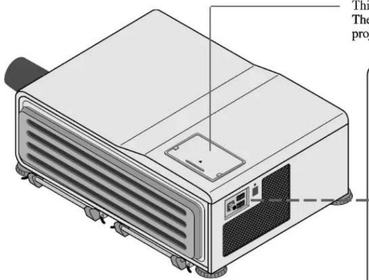
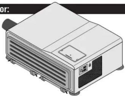
This compartment accommodates the remote control. The remote control serves as the key panel on the projector when it is plugged and fit in this compartment.
POWER ON/STANDBY Indicator
lights in green when the projector is turned on and lights in red when the projector is in standby.
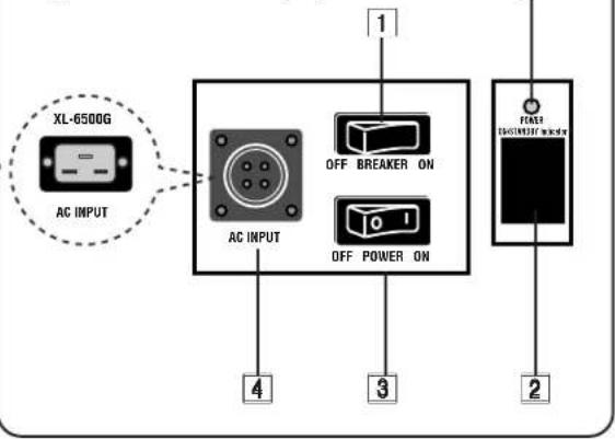
1 BBreakeSwitch
Press the switch to the ON position to turn on the breaker and press to the OFF position to turn off the breaker.
When abnormal conditions are encountered, the breaker will trip and turn the projector off.
If the projector will not be used for an extended period of time, turn off the breaker by pressing the switch to the OFF position.
2 Remote Sensor
Receives the signal from the supplied remote control when used in the wireless mode.
3 Power Switch (Main power)
To turn on the main power to the projector press the switch to the ON position (1). The STANDBY and the RC READY indicator will light.
In this condition you can start up the projector by pressing the POWER ON button on the remote control or the POWER button on the side panel.
Press to the OFF position (0) to turn the main power off.
NOTE: When turning off the main power, first return the projector to the standby condition by pressing the POWER OFF button on the remote control or the POWER button on the side panel and then turn off the main POWER switch. These procedures are necessary to protect your projector and the connected equipment.
4 AC INPUT
Connect the supplied power cord here (AC 200-240V).
5 POWER Button
Turns the projector on when the projector is in the standby condition (Main Power switch must be on and the STANDBY indicator lit). Turns the projector off after “- -” on the two digit display is blinking for three minutes.
NOTE: Do not turn off the main power while “- -” on the two digit display is blinking. During this time the lamp is cooling off.
6 POWERIndiator
Lights up when the projector is turned on.
7 SSTAANBBYIndiator
Lights up when the projector's main POWER switch is on. When the projector is used with the ISS-6020 switcher on SW1 level or SW2 level mode, this indicator flashes when the projector is not connected with the switcher correctly or when the switcher is turned off.
Lights up when the projector's main POWER switch is on. Flashes when the projector receives a signal from the remote control.
|9| LAMP Indicator
Displays the lamp on or off.
Indicator illuminates—Lamp is turned on Indicator goes out-Lamp is turned off
10 Two Digit Display
INDICATOR: Displays projector error codes. ("00" in normal operation) ON/OFF Switch: Turns the INDICATOR on or off.
11 REMOTE 2 Jacks
IN: for the wired remote control.
OUT: for daisy-chaining multiple projectors and operating them with the same remote control. To do so, connect to a second projector's IN terminal to relay the input at the IN terminal of the first projector until all the projectors are connected.
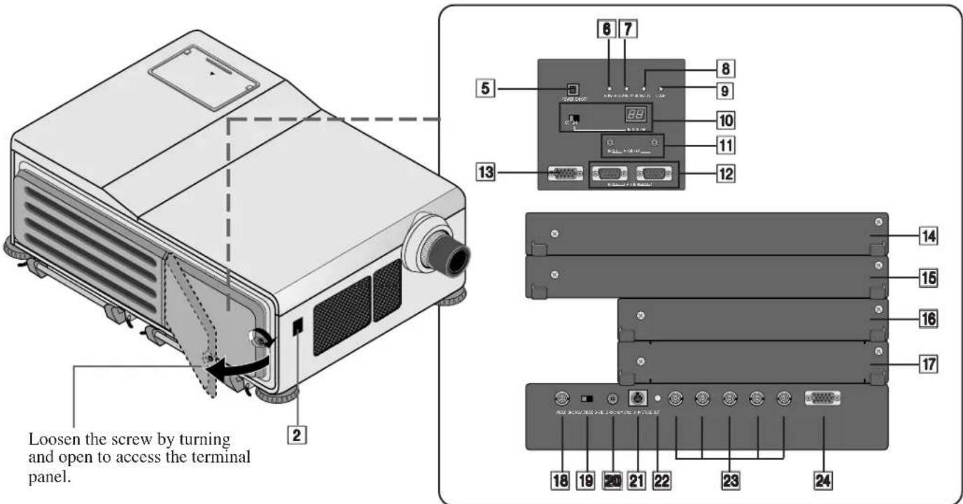
12 OPTION Connectors (D-Sub 9-pin)
For system expansion such as PC-control. IN: connect to the external equipment such as PC. OUT: for daisy-chaining multiple projectors and operating them with the same external equipment. To do so, connect to a second projector's IN terminal to relay the input at the IN terminal of the first projector until all the projectors are connected.
13 REMOTE 1 Connector (Mini D-Sub 15-pin)
This terminal allows external control of the projector from either the Switcher or from an external control. When the Switcher is used, connect to the REMOTE 1 terminal on the back of the Switcher. NOTE: The ISS-6020/ISS-6020G Switcher is compatible with this projector.
14 INPUT E
Not used.
15 INPUT D
Used for the factory-installed video processor only.
16 INPUT C
Slot for adding optional RGB or video input cards.
17 INPUT B
Slot for adding optional RGB or video input cards.
18 VIDEO Input BNC Terminal (INPUT A)
Connect to the BNC video output of the external equipment such as a VCR or laser disk player.
19 VIDEO Input Select Switch
Selects VIDEO input between BNC and RCA type.
20 VIDEO Input RCA Terminal (INPUT A)
Connect to the RCA video output of the external equipment such as a VCR or laser disk player.
21 S-VIDEO Input Terminal (INPUT A)
Connect to the S-video output of the external equipment such as a VCR with an S-video output. This terminal allows switching between S2 and S1 VIDEO input modes. See the "S-Video Mode" section for more information.
22 Active Indicator (green LED)
Lights up when the INPUT A slot is selected.
23 R/Cr, G/Y, B/Cb, H H/V and V Input Terminals (INPUT A)
Connect R,G,B,H (Horizontal sync) and V (Vertical sync) outputs of the external equipment such as the Switcher). If using a component with a combined sync (SYNC) output, connect it to the H/V terminal. Connect component video outputs of the external equipment such as DVD player.
24 OSD OUT Connector (Mini D-Sub 15-pin)
Outputs on-screen information. You can use this connector to loop your on-screen information to an external monitor.
NOTE:
1) A picture may be distorted or no picture may appear when any one of the following procedures is performed:
* An SXGA signal is input to the projector.
* A High-refresh signal is input to the projector.
2) Some types of monitor may display no image on the screen.
OPTIONAL Boards
VIDEO INPUT Board [XG VIDIN (A)]
Front view
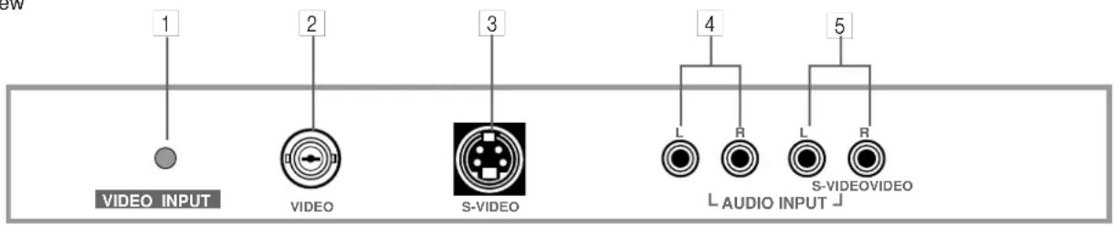
1 Active Indicator (green LED)...... Lights up when this board is selected.
2 VIDEO INPUT Terminal ...... Connects composite video output signals.
3 S-VIDEO INPUT Terminal ...... Connects S-video output signals.
4 VIDEO INPUT Terminal ...... Connect to the audio outputs of the external equipment such as a VCR.
(Not available on this model.)
5 S-VIDEO INPUT Terminal ...... Connect to the S-video audio outputs of the external equipment such as a VCR
with S-video outputs. (Not available on this model.)
RGB INPUT Board [XG RGBIN (A)]
Front view

1 Active Indicator (green LED)..... Lights up when this board is selected.
2 R Input Terminal.... Connects an Red output signal.
3 | G Input Terminal ...... Connects a Green output signal.
4 B Input Terminal.... Connects a Blue output signal.
5 H/HV Input Terminal ...... Connects horizontal sync or horizontal/vertical sync output signals.
6 | V Input Terminal ...... Connects a vertical sync output signal.
7 AUDIO Input Terminals...... Connect to the audio outputs of the external equipment such as ISS-6020/6020G.
(Not available on this model.)
RGB INPUT Board
Top view
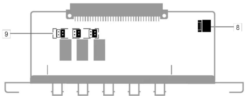
8 Rotary Switch (S1001)
9 Jumper(S1002, S1003, S1004)
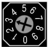
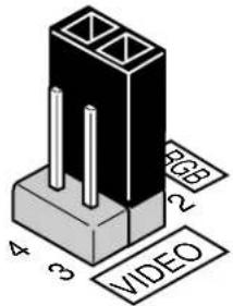
The combination of the rotary switch and the jumper pins allows the projector to accept VIDEO signals. Note that this board cannot accept RGB signals when board is set to VIDEO input.
Rotary switch (S1001)
Jumper (S1002, S1003, S1004)
Setting of Rotary switch
| No. | Mark | Input |
| 0 | VIDEO | VIDEO input |
| 1 | OPTION | Option |
| 3 | RGB | RGB input |
| 2,4-9 | Not used |
*1) No 1 is for future system expansion.
*2) No 3 is factory preset.
Table for Setting Rotary Switch and Jumpers.
| Setting of Rotary switch and Jumpers | Input Signal | Board Identification | |||
| Rotary Switch(S1001) | Jumpers | R terminal | G terminal | B terminal | |
| 0 | (2, 3) Short | VIDEO | Y | C | VIDEO |
| 3 | (1, 2) Short | R | G | B | RGB |
* indicates factory preset.
SLOT FOR OPTIONAL MODULE
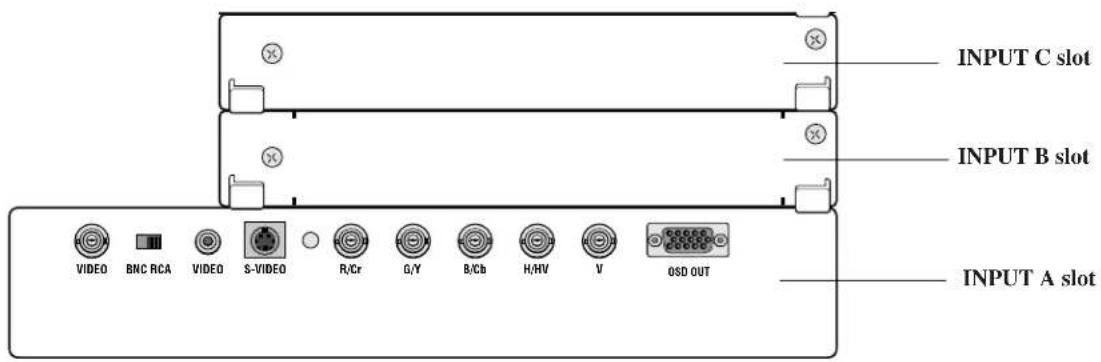
Corresponding slot number
You can also select the input signal directly by pressing the INPUT "1" through "10" button. In this case INPUT buttons function as follows:
1) When the slot A(Mother board) is selected:
INPUT 1..... RGB input
INPUT 2..... VIDEO input
INPUT 3..... S-VIDEO input
3) When the slot C (optional board) is selected:
When VIDEO board installed When RGB board installed
INPUT 7..... VIDEO input INPUT 7 ..... RGB input
INPUT 8..... S-VIDEO input
2) When the slot B (optional board) is selected:
When VIDEO board installed When RGB board installed
INPUT 4..... VIDEO input INPUT 4 ..... RGB input
INPUT 5..... S-VIDEO input
Remote control unit
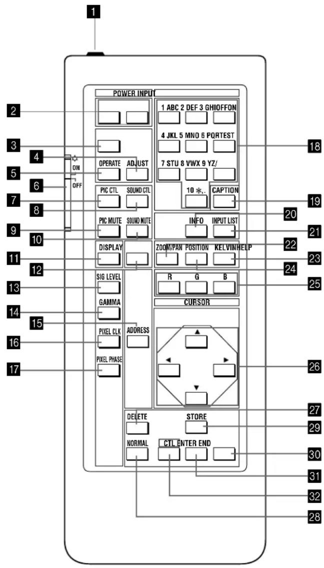
You can use your remote control with the cable or wirelessly to operate your MultiSync Hivid 6500 Projector.
If you want to use your remote control with the cable, connect one end of the cable to the jack on the remote control and the other end to the REMOTE 2 IN jack of the projector.
1 Remote Jack
Insert the supplied remote cable here.
2 POWER Buttons (ON/OFF)
Press the ON button to turn the projector on when the projector is in the standby condition (STANDBY and RC READY indicators lit). Press the OFF button to return the projector to the standby condition.
3 TEST Button
Press to display the TEST PATTERN menu from which you can select a test pattern.
4 ADJUST Button
Press to display the ADJUST menu.
5 OPERATE Button
Press to display the OPERATE menu. Hold down the CTL button and then press the OPERATE button to directly display the Lens Control adjustment screen.
6 Backlight Switch
Turns the backlight on and off.
If no button operation is made within 30 seconds with the Backlight ON, the Backlight will turn off to conserve battery life. The light stays on in standby and power-on when the remote control is used as a wired remote.
7 PIC CTL Button
Press to display the picture adjustment screen.
NOTE: Some function items will not be available depending on the type of video signal.
8 SOUND CTL Button
Press to display the VOLUME adjustment screen. You can adjust the volume of the ISS-6020/ISS-6020G
Switcher. (when used with the ISS-6020 switcher on SW1 level or SW2 level mode)
9 PICTURE (PIC) MUTE Button
Press to mute the picture. Press again to display the picture.
10 SOUND MUTE Button
Press to mute the sound. Press again to return the sound. (when used with the ISS-6020 switcher on SW1 level or SW2 level mode)
11 DISPLAY Button
Press to turn on or off the on-screen display. Pressing with CTL eliminates the on-screen display; pressing with CTL will restore display.
NOTE: Even if the on-screen display may be turned off with pressing CTL and DISPLAY, any adjustment will still change the projector's memory settings. This mode is available even when an input is switched to another or the power is turned off using the POWER OFF button on the remote control.
12 HELP Button
Press to display the explanation of the current selected function and available functions.
13 SIG LEVEL Button
Press to display the SIGNAL LEVEL menu. You can set the level for an RGB or component signal.
14 GAMMA Button
Press to display the GAMMA CORRECTON menu. You can select two options.
15 ADDRESS Button
Press to display the ADDRESS menu. Pressing with CTL allows you to specify the address for the remote control.
16 PIXEL CLK Button
Press to display the PIXEL CLOCK adjustment screen. You can adjust a picture width to the screen by adjusting the clock frequencies to eliminate the vertical banding in the image.
17 PIXEL PHASE
Press to display the PIXEL PHASE adjustment screen. You can adjust the clock phase to reduce video noise, dot interference or cross talk. (This is evident when part of your image appears to be shimmering.)
18 INPUT Button
Selects menus and switches input signals.
19 CAPTION Button
Press to display the CLOSED CAPTION menu.
20 INFO Button
Press to display the various parameters and settings of the currently displayed image. Pressing with the CTL button displays some of items available.
21 INPUT LIST Button
Press to display the memory list of the recorded input signals.
22 ZOOM/PAN Button
Press to display the ZOOM adjustment screen. The zoom function enlarge or reduce the projected image. Pressing with CTL displays the PAN adjustment screen. The pan function enlarge or reduce the selected part of an image.
23 KELVIN Button
Press to enter the KELVIN mode. You can adjust the color temperature.
24 POSITION Button
Press to enter the position mode. You can adjust the horizontal, vertical position and horizontal, vertical blanking and image size.
25 R, G, and B Buttons
The R and B buttons are used for Uniformity only.
26 CURSOR Buttons
Used for increasing and decreasing control levels, cursor movement and convergence adjustments.
27 DELETE Button
Used to delete characters or numbers you typed.
28 NORMAL Button
Returns the standard level for each signal. When pressed once, the confirmation message will be displayed. When "YES" is selected and ENTER is pressed, the data will be returned to the standard level. While holding down the CTL button, press the NORMAL button to display the LOAD menu to select the LOAD (last stored level).
29 STORE Button
Memorizes the adjustments setting of each signal separately.
When pressed once, the confirmation message “STORE?” will be displayed. When selecting “YES” and ENTER, the data will be stored in memory.
30 END Button
Ends the adjustment mode.
31 ENTER Button
Executes menu selection and switches to selected input.
32 CTL Button
Used in conjunction with other buttons, similar to a shift key on a computer.
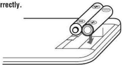
Remote Control Battery Installation
- Press firmly and slide the battery cover off.
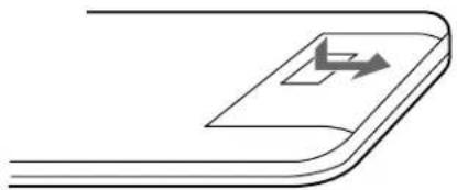
natural_image
Pure diagram of a curved surface with a rectangular object and an arrow symbol, no text or labels present.- Remove both old batteries and install new ones (AA). Ensure that you have the batteries' polarity (+/-) aligned correctly.
- Slip the cover back over the batteries until it snaps into place.
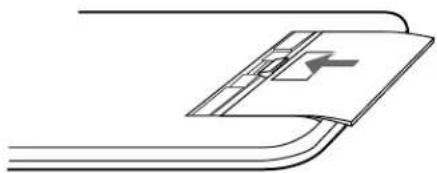
natural_image
Pure diagram of a mechanical component with no text, numbers, or symbolsNOTE: The remote control is powered by two alkaline 1.5V AA batteries.
Remote Control Precautions
- When using the remote wirelessly, you should be within 23 ft.(7 m) of the projector and at an angle of no more than 30 degrees.
- When the cable is connected to the remote control, it will not work wirelessly.
- Handle the remote control carefully.
- If the remote control gets wet, wipe it dry immediately.
- Avoid excessive heat and humidity.
- If you will not be using the remote control for a long time, remove the batteries.
- Do not mix new and old or different types of batteries.
- Avoid using the remote control as wireless with the backlight switch ON for an extended period of time. This can cause short battery life.
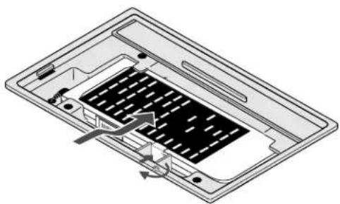
- Be sure to secure the remote control with the metal fitting when installing the projector on the ceiling and using the remote control as the key panel of the projector.
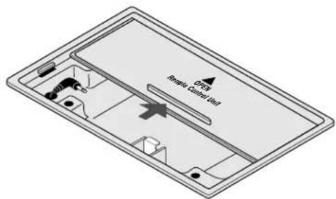
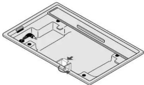
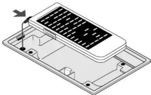
When using the remote control as the key panel on the projector:
The following steps are necessary only when the projector is installed on the ceiling.
When you use the projector in floor projection, you do not need to fasten the remote with the metal fitting. Simply open the lid and put the remote in the compartment.
natural_image
Isometric illustration of a portable electronic device with ventilation slots and control panel (no text or symbols)- Slide and open the lid.
- Loosen the screw on the metal fitting.
natural_image
Isometric technical drawing of a rectangular electronic device casing with internal components and mounting holes (no text or symbols)- Plug the mini plug into the remote jack of the remote control.
natural_image
Isometric diagram of a solar panel installation with labeled components (no text or symbols)-
Place the remote control in the compartment.
-
Tighten the screw and secure the remote control with the metal fitting.
natural_image
Technical diagram of a device casing with internal components and directional arrows indicating flow or movement (no text or symbols)
2. INSTALLATION
This section describes how to set up your MultiSync Hivid 6500 projector and how to connect video and audio sources.
Setting Up Your MultiSync Hivid 6500 Projector
To set up and use your MultiSync Hivid 6500 Projector, you must first do:
- Determine the screen size and the optional lens to be used.
NOTE: Consult your dealer for lens order and installation.
- Set up a screen or select a non-glossy white wall onto which you can project your image.
Moving The Projector
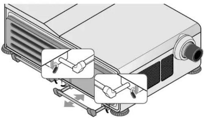
Always carry your projector by the handle. Ensure that the power cord and any other cables connecting to video sources are disconnected before moving the projector. When moving the projector or when it is not in use, cover the lens with the lens cap.
Pulling Out the Handles
Pull out the handle from the bottom side.
Retracting the Handles
Press down the two levers at the same time to retract the handle.
natural_image
Diagram of a projector with three labeled parts showing internal components and directional arrows (no text or symbols present)Selecting A Location
The further your projector is from the screen or wall, the larger the image. The minimum size the image can be projected is 80" (2 m) measured diagonally. The largest the image can be is 500" (12.7 m).
WARNING
- Only use your projector on a solid, level surface. If the projector falls to the ground, you can be injured and the projector severely damaged.
- Do not use the projector where temperatures vary greatly. The projector must be used at temperatures between 50 degrees F (10 degree C) and 104 degrees F (40 degree C).
- Do not expose the projector to moisture, dust, or smoke. This will harm the screen image.
- Ensure that you have adequate ventilation around your projector so heat can dissipate. Do not cover the vents on the bottom or back of the projector.
Screen Size and Projection Distance
- Place your projector on a flat level surface at the optimal distance from the screen or wall so you realize the size image you want. (Avoid having bright room lighting or sun light directly on the screen or wall where you'll be projecting the image.)
- Connect the power cable, remove the lens cap and turn the projector on. (If no input signal is available, the projector will display a black screen.)
- Ensure that the projector is square to the screen.
- Move the projector left or right to center the image horizontally on the screen.
- To move the projected image up or down, select the Lens Control from the Operate menu.
- Adjust the focus using the Lens Control on the Operate menu.
- Increase or reduce the size of the projected image by using the ZOOM/PAN button on the remote control.
Ceiling Installation
Installing your MultiSync Hivid 6500 Projector on the ceiling must be done by a qualified technician. Contact your NEC dealer for more information.
Do not attempt to install the projector yourself.
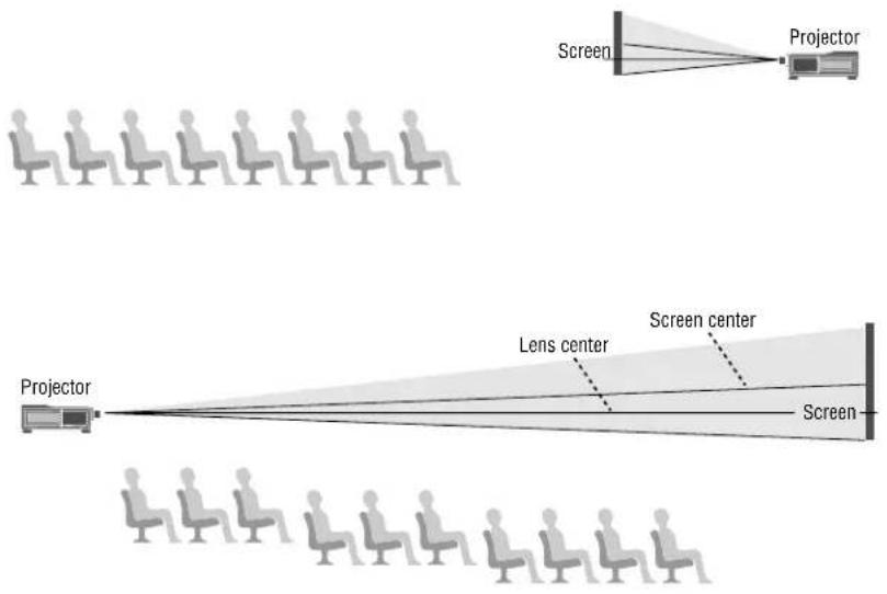
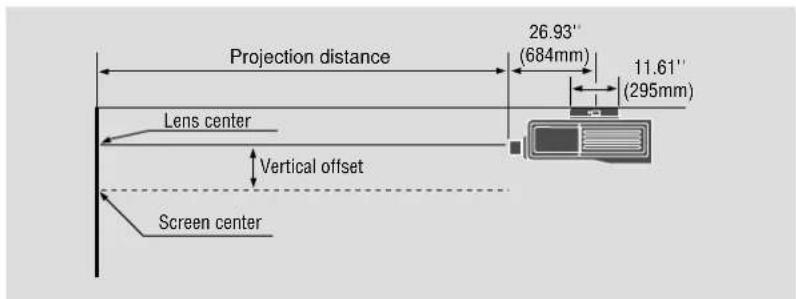
The following shows the proper relative positions of the projector and screen. Refer to the table to determine the position of installation. Install in such a way that the projector and screen are positioned in the proper direction and at the proper angle. If not, the projector's performance will be affected and its reliability will decrease. Be sure to position the projector properly.
The manufacturer will not be held responsible for any problems occurring when the projector is not installed in the proper position.
If your projector is mounted on the ceiling and your image is upside down, use PJ ORIENTATION on the ADJUST-SETTING Menu to correct the orientation. (See page 59.)
■ Projection model : XL-3500/3500G
| Lens | Model No. | XL-L1.27 XL | -L3 XL-L5 XL-L7 | XL-L1.5Z | XL-L3Z | ||
| Magnification | 1.27:1 | 3.0:1 5.0:1 | 7.0:1 | Zoom1.5-3.0 | Zoom3.0-7.0 | ||
| Screen size (Diagonal) | 100" | 2.58m102in | 6.10m240in | 10.16m400in | 14.22m560in | 3.05-6.10m120-240in | 6.10-14.22m240-600in |
| 200" | 5.16m203in | 12.19m480in | 20.32m800in | 28.45m1120in | 6.10-12.19m240-480in | 12.19-28.45m480-1120in | |
| 300" | 7.74m305in | 18.29m720in | 30.48m1200in | 42.67m1680in | 9.14-18.29m360-720in | 18.29-42.67m720-1680in | |
| 400" | 10.32m406in | 24.38m960in | 40.64m1600in | 56.90m2240in | 12.19-24.38m480-960in | 24.38-56.90m960-2240in | |
| 500" | 12.90m508in | 30.48m1200in | 50.80m2000in | 71.12m2800in | 15.24-30.48m600-1200in | 30.48-71.12m1200-2800in | |
| Vertical offset | 1/2V | 1/2V 1/2V 1/2V | 1/4V 1/4V | ||||
| V=Screen Height (inch) | Fixed focal length lens | Zoom lens | |||||
■ Projection model : XL-6500/6500G
| Lens | Model No. | XL-L1.27 | XL-L3 XL- | L5 XL-L7 | XL-L1.5Z | XL-L3Z | HVL-X1Z | HVL-X2Z | HVL-X3Z | |
| Magnification | 1.0:1 2.3:1 3.9:1 | 5.5:1 | Zoom1.2-2.3 | Zoom2.3-5.5 | Zoom1.5-2.5 | Zoom2.5-4 | Zoom4-7 | |||
| Screen size (Diagonal) | 100" | 2.0m80in | 4.7m184in | 7.9m312in | 11.2m440in | 2.4-4.7m96-184in | 4.7-11.2m184-440in | 3.0-5.1m120-200in | 5.1-8.1m200-320in | 8.1-14.2m320-560in |
| 200" | 4.1m160in | 9.3m368in | 15.8m624in | 22.4m880in | 4.9-9.3m192-368in | 9.3-22.4m368-880in | 6.1-10.2m240-400in | 10.2-16.3m400-640in | 16.3-28.4m640-1120in | |
| 300" | 6.1m240in | 14.0m552in | 23.8m936in | 33.5m1320in | 7.3-14.0m288-552in | 14.0-33.5m552-1320in | 9.1-15.2m360-600in | 15.2-24.4m600-960in | 24.4-42.7m960-1680in | |
| 400" | 8.1m320in | 18.7m736in | 31.7m1248in | 44.7m1760in | 9.8-18.7m384-736in | 18.7-44.7m736-1760in | 12.2-20.3m480-800in | 20.3-32.5m800-1280in | 32.5-56.9m1280-2240in | |
| 500" | 10.2m400in | 23.4m920in | 39.6m1560in | 55.9m2200in | 12.2-23.4m480-920in | 23.4-55.9m920-2200in | 15.2-25.4m600-1000in | 25.4-40.6m1000-1600in | 40.6-71.1m1600-2800in | |
| Vertical offset | ±1/5.1V | ±1/1.5V | ±1/5.1V | ±1/5.1V | 0 | 0 | ±1/2.1V | ±1/2.1V | ±1/3.8V | |
| V=Screen Height (inch) | Fixed focal length lens Zoom lens | Zoom lens | ||||||||
NOTE: "Vertical Offset" refers to as movable range between lens center and screen center. Vertical offset is decided by ratio of screen height (V).
Example: When using a 100" screen (4:3) and XL-6500 with the lens (HVL-X1Z), you can get 29 inches(0.73m) of your vertical offset by using the formula (100 x 3/5 x 1/2.1) and you can make your screen height larger by 29 inches(0.73m).
*For screen sizes between 80" and 500" not indicated on the above table, use the following proportional formula:
Diagonal screen size (4:3) x 4/5 = Screen width W(Screen width) x magnification = Projection distance
Unit=inches
NOTE: The margin of error for projection distance is +/- 3% in fixed-focal-length lens and +/- 5% in zoom lens.
Nine lenses are available. The four are fixed-focal-length lenses; the two are zoom lenses.
Order lens from your NEC dealer using lens's model number. Consult your NEC dealer for lens installation and replacement.
Reflecting The Image
Using a mirror to reflect your projector's image enables you to enjoy a much larger image. Contact your NEC dealer if you need a mirror.
If you're using a mirror and your image is inverted, use the ADJUST-SETTING Menu to access to correct the orientation. (See page 59.)
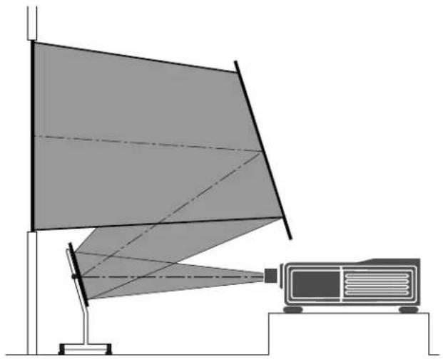
natural_image
Diagram of a projector setup with a triangular reflector and base unit (no text or symbols)Rear Screen Projection
You can use your MultiSync Hivid 6500 to project an image from the rear onto a transparent screen. The distance the projector must be from the screen is the same as if you were projecting the image from the front. Contact your NEC dealer if you need a transparent screen.
If you're projecting the image from the rear and your image is inverted, use the ADJUST-SETTING Menu to access to correct the orientation. (See page 59.)
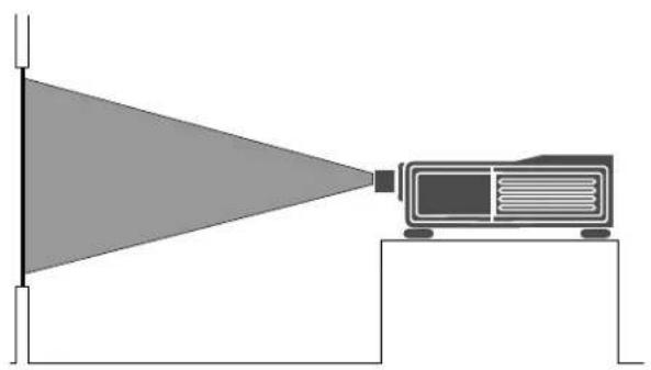
natural_image
Diagram showing a projector projecting off a wall-mounted base (no text or symbols present)EXAMPLES OF CONNECTIONS.
CAUTIONS ON CONNECTIONS:
- Unplug the projector and other equipment from the AC supply before making connections.
- Make sure that the plug of the power cord is properly connected to the power outlet. A loose connection may cause hum or noise.
- Confirm your connection layout with the user's manual accompanying the equipment to be connected with the ISS-6020/ISS-6020G Switcher.
When Used in Stand Alone Operation
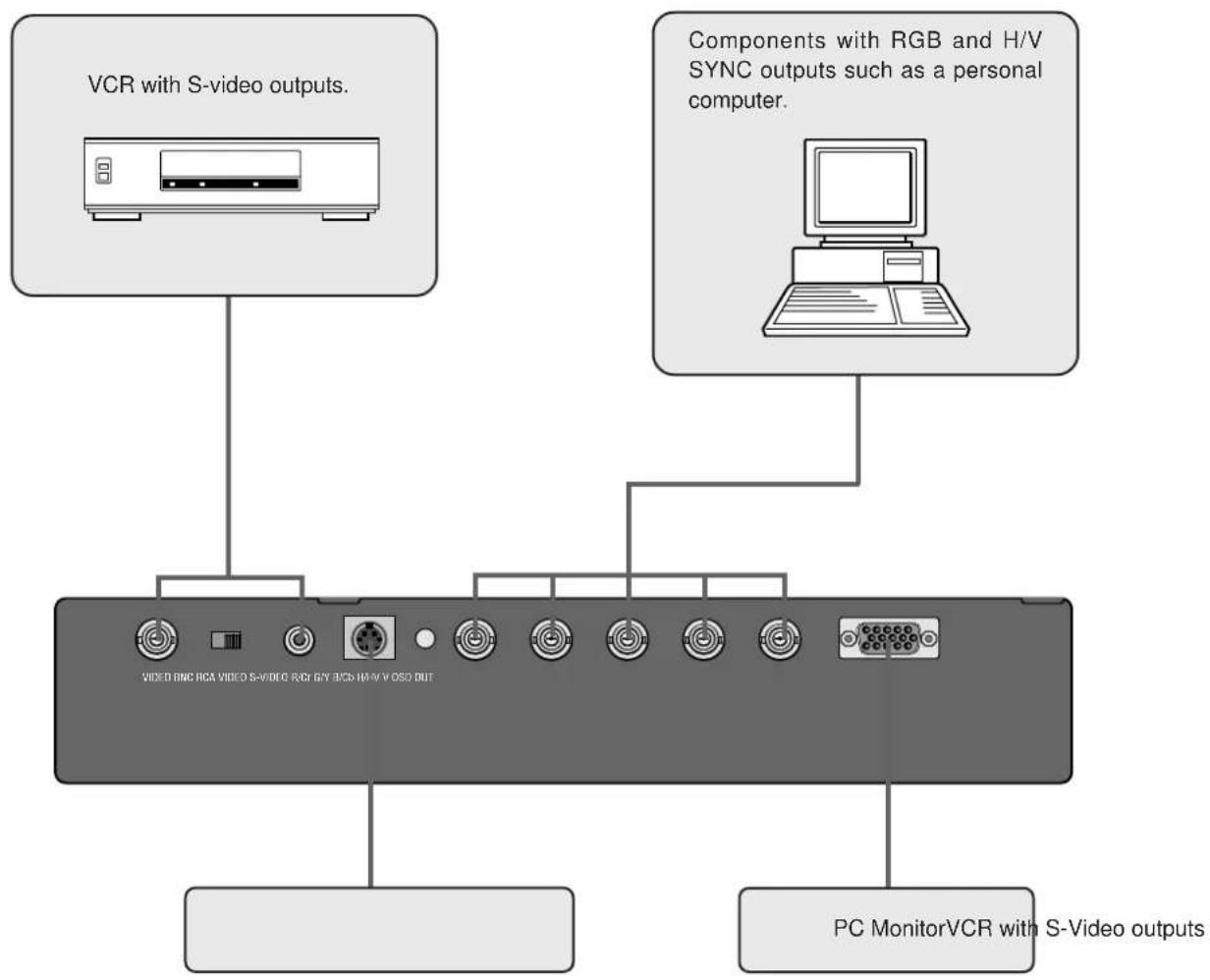
flowchart
graph TD
    A["VCR with S-video outputs."] --> B["PC MonitorVCR with S-Video outputs"]
    C["Components with RGB and H/V SYNC outputs such as a personal computer."] --> D["PC MonitorVCR with S-Video outputs"]
- Make sure that the STANDALONE mode is selected from the CONNECT CONDITION menu. See page 71 for connecting the Switcher.
When Used with One Switcher (ISS-6020/ISS-6020G)
Up to 10 input signals can be accepted when the projector is connected to one Switcher. Using the projector with the Switcher allows easy adjustment and signal selection.
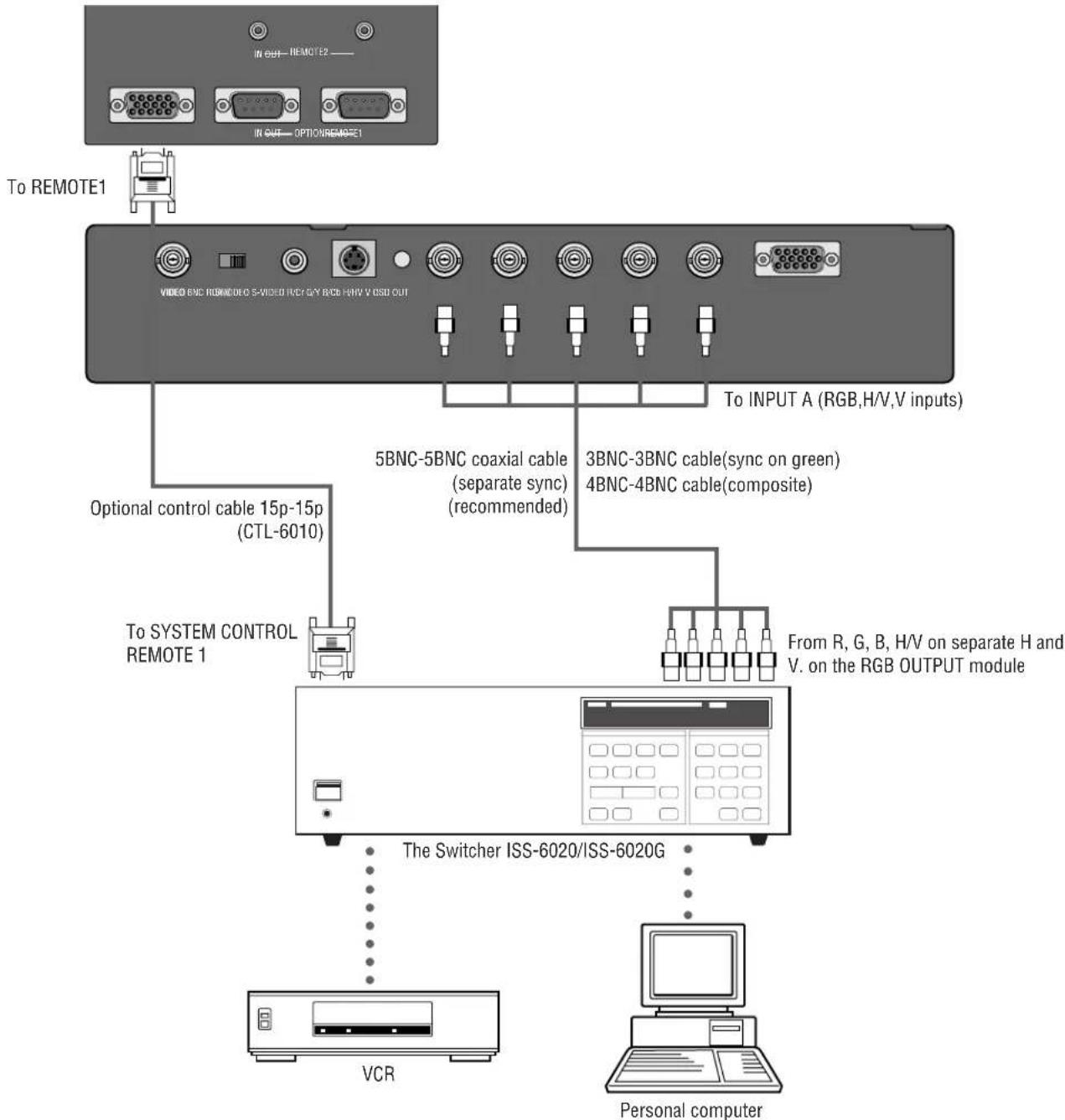
flowchart
graph TD
    A["To REMOTE1"] --> B["VIDEO END REMOTE0 S-VI/DND I/O/SPY BOX H/H/V OSD OUT"]
    B --> C["To INPUT A (RGB,H/V,V inputs)"]
    B --> D["5BNC-5BNC coaxial cable (separate sync) (recommended)"]
    D --> E["3BNC-3BNC cable(sync on green)"]
    D --> F["4BNC-4BNC cable(composite)"]
    B --> G["Optional control cable 15p-15p (CTL-6010)"]
    B --> H["To SYSTEM CONTROL REMOTE 1"]
    H --> I["From R, G, B, H/V on separate H and V. on the RGB OUTPUT module"]
    I --> J["The Switcher ISS-6020/ISS-6020G"]
    J --> K["VCR"]
    J --> L["Personal computer"]
- Make sure that the SW1 LEVEL mode is selected from the CONNECT CONDITION menu. See page 71 for the information in detail.
- For more information on the Switcher, refer to the user's manual accompanying the ISS-6020/ISS-6020G Switcher.
- All cables mentioned above are optional.
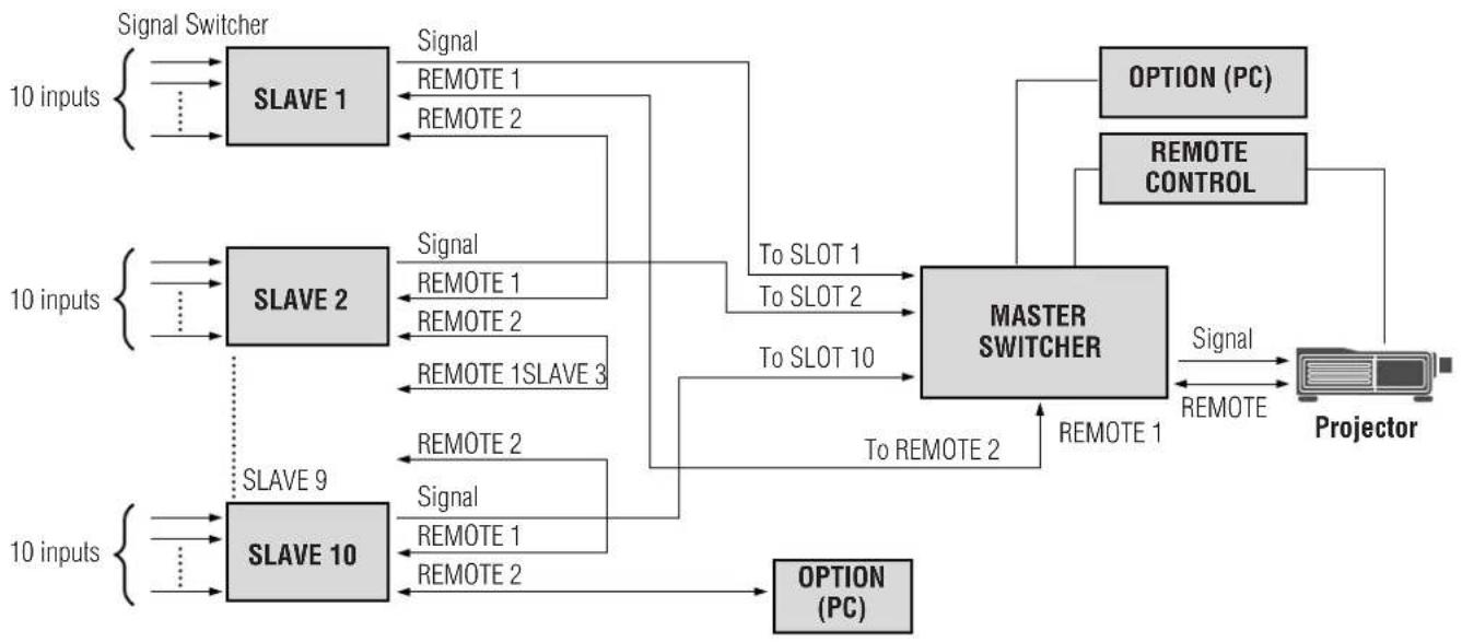
When Used with Two or More Switchers (100 Inputs)
Up to 100 inputs can be accepted using the Switcher.
How to make connections:
① Connect the REMOTE 1 terminal of the master Switcher to the REMOTE 1 of the projector using the optional control cable (15p-15p/CTL-6010).
② Next connect the REMOTE 2 terminal of the master Switcher to the REMOTE 1 terminal of the first slave Switcher using the same optional control cable as mentioned above. Third, connect the REMOTE 2 terminal of the first slave to the REMOTE 1 of the second slave, and the REMOTE 2 terminal of the second slave to the REMOTE 1 terminal of the third slave (— and the REMOTE 2 of the ninth slave to the REMOTE 1 of the tenth slave). Connect all the Switchers with optional control cables.
NOTE:
- Be sure to set all the slide switches (S8603) of the Switcher to RS-422 positions. Set the one on the last slave Switcher to the appropriate position to match the connected equipment such as a personal computer. (RS-422/RS-232C for PC control of projector)
- Set the DIP switch S8601 of the Switcher.
flowchart
graph TD
    subgraph_Signal_Switcher["Signal Switcher"]
        A1["SLAVE 1"] -->|Signal| B1["MASTER SWITCHER"]
        A2["SLAVE 2"] -->|Signal| B1
        A3["SLAVE 9"] -->|Signal| B1
        A4["SLAVE 10"] -->|Signal| B1
        A1 -->|REMOTE 1| B1
        A2 -->|REMOTE 1| B1
        A3 -->|REMOTE 2| B1
        A4 -->|REMOTE 2| B1
        A1 -->|REMOTE 2| B2["PROJECTOR"]
        A2 -->|REMOTE 2| B2
        A3 -->|REMOTE 2| B2
        A4 -->|REMOTE 2| B2
    end
    Note1["10 inputs"] --> A1
    Note2["10 inputs"] --> A2
    Note3["10 inputs"] --> A3
    Note4["10 inputs"] --> A4
    Note5["10 inputs"] --> A5
    Note6["10 inputs"] --> A6
    Note7["10 inputs"] --> A7
    Note8["10 inputs"] --> A8
    Note9["10 inputs"] --> A9
    Note10["10 inputs"] --> A10
    Note11["10 inputs"] --> A11
    Note12["10 inputs"] --> A12
    Note13["10 inputs"] --> A13
    Note14["10 inputs"] --> A14
    Note15["10 inputs"] --> A15
    Note16["10 inputs"] --> A16
    Note17["10 inputs"] --> A17
    Note18["10 inputs"] --> A18
    Note19["10 inputs"] --> A19
    Note20["10 inputs"] --> A20
    Note21["10 inputs"] --> A21
    Note22["10 inputs"] --> A22
    Note23["10 inputs"] --> A23
    Note24["10 inputs"] --> A24
    Note25["10 inputs"] --> A25
    Note26["10 inputs"] --> A26
    Note27["10 inputs"] --> A27
    Note28["10 inputs"] --> A28
    Note29["10 inputs"] --> A29
    Note30["10 inputs"] --> A30
    Note31["10 inputs"] --> A31
    Note32["10 inputs"] --> A32
    Note33["10 inputs"] --> A33
    Note34["10 inputs"] --> A34
    Note35["10 inputs"] --> A35
    Note36["10 inputs"] --> A36
    Note37["10 inputs"] --> A37
    Note38["10 inputs"] --> A38
    Note39["10 inputs"] --> A39
    Note40["10 inputs"] --> A40
    Note41["10 inputs"] --> A41
    Note42["10 inputs"] --> A42
    Note43["10 inputs"] --> A43
    Note44["10 inputs"] --> A44
    Note45["10 inputs"] --> A45
    Note46["10 inputs"] --> A46
    Note47["10 inputs"] --> A47
    Note48["10 inputs"] --> A48
    Note49["10 inputs"] --> A49
    Note50["10 inputs"] --> A50
    Note51["10 inputs"] --> A51
    Note52["10 inputs"] --> A52
    Note53["10 inputs"] --> A53
    Note54["10 inputs"] --> A54
    Note55["10 inputs"] --> A55
    Note56["10 inputs"] --> A56
    Note57["10 inputs"] --> A57
    Note58["10 inputs"] --> A58
    Note59["10 inputs"] --> A59
    Note60["10 inputs"] --> A60
    Note61["10 inputs"] --> A61
    Note62["10 inputs"] --> A62
    Note63["10 inputs"] --> A63
    Note64["10 inputs"] --> A64
    Note65["10 inputs"] --> A65
    Note66["10 inputs"] --> A66
    Note67["10 inputs"] --> A67
    Note68["10 inputs"] --> A68
    Note69["10 inputs"] --> A69
    Note70["10 inputs"] --> A70
    Note71["10 inputs"] --> A71
    Note72["10 inputs"] --> A72
    Note73["10 inputs"] --> A73
    Note74["10 inputs"] --> A74
    Note75["10 inputs"] --> A75
    Note76["10 inputs"] --> A76
    Note77["10 inputs"] --> A77
    Note78["10 inputs"] --> A78
    Note79["10 inputs"] --> A79
    Note80["10 inputs"] --> A80
    Note81["10 inputs"] --> A81
    Note82["10 inputs"] --> A82
    Note83["10 inputs"] --> A83
    Note84["10 inputs"] --> A84
    Note85["10 inputs"] --> A85
    Note86["10 inputs"] --> A86
    Note87["10 inputs"] --> A87
    Note88["10 inputs"] --> A88
    Note89["10 inputs"] --> A89
    Note90["10 inputs"] --> A90
- Make sure that the SW2 LEVEL mode is selected from the CONNECT CONDITION menu. See page 71 for the information in detail.
- Refer to the user's manual accompanying the Switcher.
• Cables mentioned are not included with the projector.
Set the DIP switch (S8601) of the Switcher as follows:
NOTE: Slave numbers 1 to 10 must correspond to the master's slot numbers 1 to 10.
| ISS-6020ISS-6020G | Output to Setting of S8601 | |
| Master | The Projector | 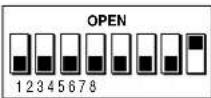 |
| Slave 1 | Slot 1 of the Master | 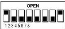 |
| Slave 2 | Slot 2 of the Master | 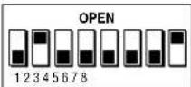 |
| Slave 3 | Slot 3 of the Master | 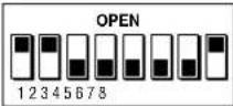 |
| Slave 4 | Slot 4 of the Master | 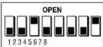 |
| Slave 5 | Slot 5 of the Master | 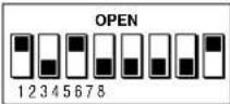 |
| Slave 6 | Slot 6 of the Master | 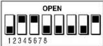 |
| Slave 7 | Slot 7 of the Master | 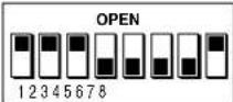 |
| Slave 8 | Slot 8 of the Master | 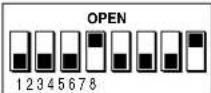 |
| Slave 9 | Slot 9 of the Master | 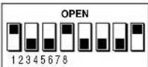 |
| Slave 10 | Slot 10 of the Master | 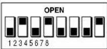 |
REMOTE 1 Terminal
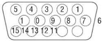
This terminal is used for either connecting the ISS-6020/ISS-6020G Switcher or a third party external control device. When the Switcher is used, connect it with the optional control cable (15-15 pin; 50 ft./16m; CTL-6010) to this terminal.
When used with the Switcher.
| Pin No. FUNCTION | |
| 1, 2, 6 and 7 Sending and receiving data when the Switcher is used. | |
| 9 Identifying the Projector | |
| 15 Ground | |
| Others Used inside the Projector. Normally set to OPEN. | |
When using with the Switcher ISS-6020/ISS-6020G, connect no. 1,2,6,7,9 and 15 pins of the projector to the same no. pins of the switcher as shown below.
REMOTE 1 terminal of the Projector mini D-sub 15 pin (male)
REMOTE 1 terminal of the Switcher mini D-sub 15 pin (male)
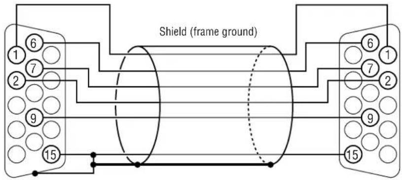
Pins without a number are open.
Pin Configuration of Optional CTL-6010 Cable
When used in stand alone operation.
| Pin No. | SHORT/OPEN | FUNCTION | |||
| 14 | SHORTOPEN | External control mode ONExternal control mode OFF | |||
| 5 | SHORTOPEN | POWER ONPOWER OFF | |||
| 10 | SHORTOPEN | PICTURE MUTE ONPICTURE MUTE OFF | |||
| 4,8,12,11 | 11 | 12 | 8 | 4 | |
| OPEN | OPEN | OPEN | OPEN | INPUT-A RGB | |
| OPEN | OPEN | OPEN | SHORT | VIDEO | |
| OPEN | OPEN | SHORT | OPEN | S-VIDEO | |
| OPEN | OPEN | SHORT | SHORT | COMPONENT | |
| OPEN | SHORT | OPEN | OPEN | COMPONENT(HDTV) | |
| OPEN | SHORT | OPEN | SHORT | INPUT-B RGB | |
| OPEN | SHORT | SHORT | OPEN | VIDEO | |
| OPEN | SHORT | SHORT | SHORT | S-VIDEO | |
| SHORT | OPEN | OPEN | OPEN | COMPONENT | |
| SHORT | OPEN | OPEN | SHORT | COMPONENT(HDTV) | |
| SHORT | OPEN | SHORT | OPEN | INPUT-C RGB | |
| SHORT | OPEN | SHORT | SHORT | VIDEO | |
| SHORT | SHORT | OPEN | OPEN | S-VIDEO | |
| SHORT | SHORT | OPEN | SHORT | COMPONENT | |
| SHORT | SHORT | SHORT | OPEN | COMPONENT(HDTV) | |
The term "SHORT" means to connect with pin 15
- When in the external control mode, the POWER, INPUT and PICTURE MUTE buttons on the remote control will not function.
NOTE: Pin 13 is the external remote signal terminal. The projector can be controlled by the same format signal as the supplied remote control from the external controller regardless of setting Pin 14.
NOTE: When turning off the power to the projector using the external control, do not disconnect the plug from the power outlet. These procedures are to protect your projector and the connected equipment.

3. OPERATION
This section describes how to select a computer or video source and how to adjust the picture and sound, register a new signal and other settings and adjustments for set-up
General Controls
Before you turn on your MultiSync Hivid 6500 Projector ensure that the computer or video source is turned on and that your lens cap is removed.
1. Turn On The Projector
The breaker switch and the main power switch are on the back panel of the MultiSync Hivid 6500 Projector. By turning these switch on, the projector will go into its standby mode and the POWER ON/STANDBY indicator will glow red. Only after you press the 'On' button on the remote control or projector cabinet will the POWER ON/STANDBY light turn to green and the projector become ready to use.
2. Select The Computer Or Video Source
Press the INPUT button on the remote control to display the image. Or press the Operate button on the remote control and use the Source Selection to select your video source: Video, S-Video, RGB or Y/Cr/Cb.
NOTE: When the message "New Signal" is displayed, register the signal in the Source Registry menu.
3. Adjust The Image and The Sound
Press the PIC CTL button on the remote control or use the Operate-Picture Control menu to adjust the picture. Press the SOUND CTL button on the remote control or use the Operate-Sound Control menu to increase or decrease the volume.
4. Turn Off The Projector
First press the POWER button on the remote control or the projector cabinet. The STANDBY light will glow. Allow the fan to cool the projector for three minutes. This will extend the life of the lamp. Then turn off the main power switch on the back panel. The power light will go out. Last turn off the breaker switch on the back panel.
IMPORTANT:
- The projector should be unplugged if it will not be used for an extended period.
- If you want to turn off the image briefly (five minutes or less), press the PIC MUTE button instead of turning the projector off and on.
- The projector will display a message "No Signal !!" if no input signal is present.
- Do not turn the projector off and then immediately back on. The Projector needs to cool down for three minutes before it is powered on again.
CAUTION: Do not unplug the projector or turn off the main power while the cooling fan is on and the "--" on Two Digit display is blinking for three minutes.
Using The On-Screen Menus
- Press the OPERATE or ADJUST button on the remote control to display the Operate or Adjust menu.
- Use the ☑ or ☒ button on the remote control to highlight the "1. Ope.", "2. Adj." or "3. Help" in yellow and the selected menu will drop down.
- Press the ⚠ button to highlight the item you want to adjust or set in the selected menu.
- Press the ENTER button on the remote control to select the item.
- Adjust the level or turn the selected item on or off by using the ☐ ☒ or ☑ ☒ buttons on the remote control. The on-screen gauge will show you the amount of increase or decrease.
- Press the STORE button on the remote control to store the change.
NOTE: The change is stored automatically when the Automatic Save ("Auto Data Store") Feature mode is set to "ENABLE". See page 64.
- Repeat steps 2-5 to adjust an additional item, or press the END button on your remote control to quit.
Adjustment Mode
The Adjustment mode contains various adjustment items for set-up.
Open the Adjustment menu and select the item you wish to adjust.
To display the Adjustment menu, proceed as follows:
① Press the ADJUST button.
- The projector may ask for your passcode.
② Enter your registered passcode.
When a passcode has not been registered:
- Since no passcode is programmed at the factory, pressing the ADJUST button will open the Adjustment menu.
- See “Entering Passcode”, “Registering Passcode”, “Changing Your Passcode” and “Canceling Your Passcode” on pages 52 through 58.
- Since no passcode is programmed at the factory, pressing the ADJUST button will open the Adjustment menu. - See “Entering Passcode”, “Registering Passcode”, “Changing Your Passcode” and “Canceling Your Passcode” on pages 52 through 58.
When your passcode has already been registered:
- When finishing the Adjustment mode, the “RETURN USER MODE?” menu will be displayed. If you select “YES” and press ENTER to end the Adjustment mode, you will have to enter your passcode to re-enter the Adjustment mode.
- When finishing the Adjustment mode by either selecting "NO" or pressing END, you do not need to enter your passcode to re-enter the Adjustment mode. To exit the Adjustment mode temporarily during adjusting, select "NO".
- When finishing the Adjustment mode, the “RETURN USER MODE?” menu will be displayed. If you select “YES” and press ENTER to end the Adjustment mode, you will have to enter your passcode to re-enter the Adjustment mode. - When finishing the Adjustment mode by either selecting “NO” or pressing END, you do not need to enter your passcode to re-enter the Adjustment mode. To exit the Adjustment mode temporarily during adjusting, select “NO”.
Passcode?
* * * *
Menu Descriptions & Functions
Access of all set-up functions is done through the menu system. Depending upon button selection, your desired screen will be displayed as shown below:
NOTE: Some function items will not be available on the input video signal or connected peripheral equipment. Functions not available are indicated in gray.
Operate Menu Adjust Menu Help
| 1. Ope. 2. Adj 3. Help |
| -Operate- |
| 1. Source Select |
| 2. Source Information |
| 3. Picture Control ▷ |
| 4. Lens Control |
| 5. Display Control ▷ |
| 6. Image Control ▷ |
| 7. Sound Control |
| 8. Closed Caption |
| 9. Timer Setting ▷ |
enu
| 1. Ope. 2. Adj 3. Help | |
| -Adjustment- | |
| 1. Source Registry | ▷ |
| 2. Amplitude | |
| 3. White Balance | |
| 4. Signal Level | |
| 5. Uniformity | ▷ |
| 6. Display Function | ▷ |
| 7. Lamp Mode | |
| 8. Set Option | ▷ |
| 1. Ope. 2. Adj 3. Help |
| -Help-1. Help2. Topics3. Set Information |
Typical keys on the remote control work as follows:
OPERATE : Accesses the Operate menu.
ADJUST : Accesses the Adjust menu.
☐ : Selects the next upper item in the menu. Or increases the adjustments.
☑ : Selects the next lower item in the menu. Or decreases the adjustments.
☒: Selects the next right side item in the menu or task bar. Or increase the adjustments.
☒ : Selects the next left side item in the menu or task bar. Or decrease the adjustments.
ENTER : Proceeds to the selected menu choice or to the selected adjustment.
END : Returns to the previous menu or exits the selected function.
INPUT(1-10): Directly switches to the corresponding input or opens the corresponding sub menu or item.
About Task bar
The mens (Operate, Adjust or Help) has the common bar across the top of the menu. This is called the Task bar. A press of either of the OPERATE or ADJUST button on the remote control displays the task bar with the menu.
On-Screen Menu Elements:
Highlight: Indicates the selected menu in yellow; indicates the selected control in white back.
Delta symbol (▷) in the menu or sub menu: Indicates further choices are available. Use the ENTER button to open the pull-down menu.
Inverted delta symbol ( ) in the adjustment or setting screen: Indicates further choices are available. Use the ENTER button to open the pull-down menu. Note that a solid inverted delta symbol ( ) indicates the item is currently selected.
Storing Projector Settings (Automatic Save Feature)
You have two options to store projector settings in the memory: automatically and manually.
* The Automatic Save Feature mode has been set to "DISABLE" by factory. For information on setting, see "Automatic Auto Data Store" on page 64.
- When the Automatic Save Feature mode is set to "ENABLE", projector settings will be stored in the projector's memory automatically.
Settings are stored automatically when any one of the following procedures is performed:
• One input is switched to another.
• The projector is turned off.
• After every 10 minutes of elapsed time.
■ When the Automatic Save Feature mode is set to "DISABLE", projector settings can be stored in the projector's memory manually.
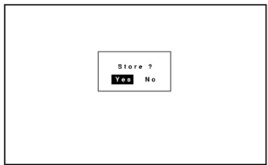
When you try to return the source screen by pressing END several times, the "STORE?" menu is displayed.
To manually save settings, proceed as follows:
-
Use the END button to display the "STORE" menu from the current adjustment screen or menu.
-
Use the CURSOR ☑ or ☒ button to highlight "Yes" or "No" and press ENTER.
Items to select
- Yes ---- Overwrites the currently projected signal and saves the settings. Note that "Yes" is available only for registered signals.
- No ---- Does not save settings.
Basic Operation (Operate Menu)
Source Select
Enables you to select a source such as a VCR, laser disk player, DVD player, or computer.
- Use the CURSOR button to highlight the source to be switched to and press the ENTER to the selected source.
NOTE:
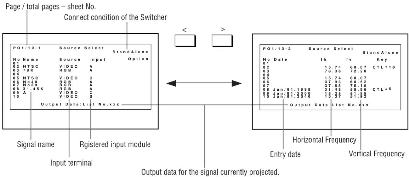
- The Source Select menu has 10 pages. Each page consists of two sheets. Press the button to go on to the next sheet or the previous sheet.
- To advance to the next page or to the previous page, hold down the CTL button then press the CURSOR ☐/☒ or ☑/☒ . To directly access the page, hold down the CTL button then any one of the INPUT buttons.
To select a source using the INPUT buttons on the remote control when no menus are displayed:
1) Press the INPUT "0" button.
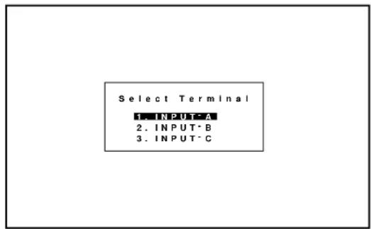
- The Select Terminal menu is displayed.
2) Use the CURSOR ☑ button to select an input terminal you wish to input.
3) Press the ENTER button to execute selection and to switch to the selected input. To cancel, press any one of the INPUT buttons.
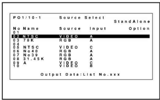
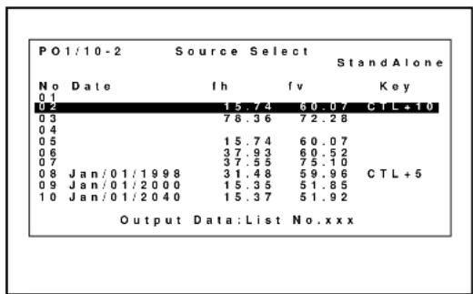
INPUT SELECT List Format
NOTE:
- While you are viewing a source screen, you can also select the input signal directly by pressing the INPUT "1" through "10" button. In this case INPUT buttons function as follows:
When using the projector in stand alone operation:
| Input Module\Input Mode | RGB | VIDEO | S-VIDEO | COMPONENT | COMPONENT (HDTV) | Slot Selection |
| A | 1 | 2 | 3 | 4 | 5 |
1
Numbers designate INPUT buttons on the remote control.
When using the projector with the ISS-6020/ISS-6020G:
INPUT 1 through 10 → Selects the corresponding number slot of the ISS-6020/ISS-6020G
When using the projector with two ISS-6020/ISS-6020G or more:
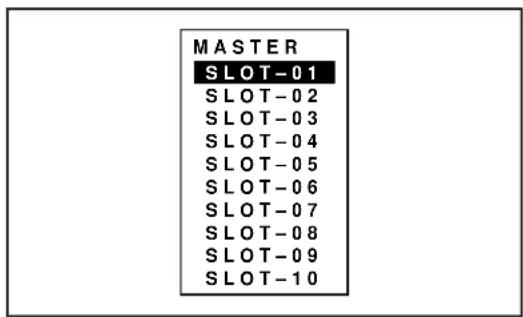
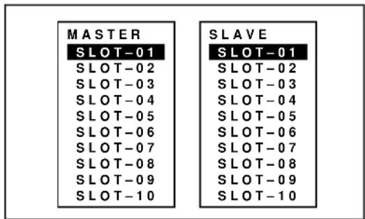
To switch to another input signal, enter the master slot number, then the slave slot number by using INPUT buttons and press ENTER.
Example: If you want to select a signal from the no.3 slot of the slave Switcher which is connected to the no.2 slot of the master Switcher, first press the INPUT "2" button, then the INPUT "3" button and then press ENTER.
- You can switch to any input signal of NO 01 through10 on the Source Select list by holding down the CTL button and pressing one of the INPUT buttons corresponding to the input number. To activate this function you must first select ENABLE in the Direct Key. For further details, contact your dealer.
- If there are two or more memory locations that contain the same signal information the projector will reference the signal nearest the beginning of the list. To select the next signal use the CURSOR △ or ▼ button and press ENTER.
Source Information
Provides and changes information for the parameters of your current projected source.
NOTE: For other registered signals, change their parameters on the Source Registry menu.
The menu items you can display, change or specify are as follows:
| Source Name---- | Changes a user name that has previously been entered. |
| Direct Key ---- | Assigns settings of source to each INPUT button (1-10) with CTL. |
| Input Slot ---- | Selects an input terminal for the registered signal when you need to do due to adding optional equipment. |
| Display Mode ---- | Selects the screen display mode. |
| Signal System---- | Displays the signal system of the current source such as RGB, Video, S-Video, or Component signal. |
| Video System ---- | Displays the current video standard. |
| Sync Frequency (H/V)---- | Displays the current sync frequency. |
| Sync Polarity (H/V) ---- | Displays the current sync polarity. |
| Sync System ---- | Selects the detection method of the sync signal. |
| Sync Termination---- | Selects the impedance of the sync signal. |
| Scale Mode ---- | Enables or disables to enlarge or reduce the image. To take effect, press and hold CTL then press ZOOM/PAN; to cancel it, do the same again. |
| Input Sig.Size ---- | Specifies the picture size of input signal. |
| Output Sig.Size ---- | Specifies the picture size of output signal. |
| Color Matrix ---- | Selects the mode to match the output format of an HDTV or DVD signal. |
| CTI Control ---- | Turns this feature on so you can make the color sharper. |
| (Color Transient Improvement) | |
| Noise Reduction ---- | Turns this feature on so video noise can be reduced. |
| Source Select Counter ---- | Resets the number of times a signal is selected for display. |
| Source Display Timer ---- | Resets the time of signal display. |
Use the CURSOR ☑ button to select the item you want to view or set.
| Source Information Page1/3 | |
| Source Name | [ ] |
| Direct Key | [Not Used ☑] |
| Input Slot | [INPUT A☑] |
| Display Mode | [GRAPHICS ☑] |
| Signal System | RGB |
| Video System | |
| Sync Frequency | fH= 15.74KHzfV= 61.23Hz |
| Sync Polarity | HD(+) VD(+) |
| Source Information Page2/3 | |
| Sync System | [Auto ☑]Mix Sync |
| Sync Termination | [75Ω ☑] |
| Scale Mode | [None Scale ☑] |
| Input Sig. Size | H:1024 V:768 |
| Output Sig. Size | H:1024 V:768 |
| Source Information Page3/3 | |
| Color Matrix | [Default ☑] |
| CTI Control | [OFF ☑] |
| Noise Reduction | [OFF ☑] |
| Select Counter | 0000 |
| Display Timer | 0000H 00M |
The following items can be set:
■ Source Name
To change the source name or input a new source name by selecting one character at a time with the INPUT buttons 1 through 10 and by moving the cursor with the CURSOR button.
Only after completely finishing the selection of the characters, press ENTER.
- If you have made an error, use the CURSOR button and reenter the correct letter or number.
To delete one character, move the highlight to the character to be deleted and then press the NORMAL button.
To delete all the entered name, hold down the CTL button then press the NORMAL button.
- The above is the same procedure of the signal entry. See To change the source name or input a new source name by selecting one character at a time with the INPUT buttons 1 through 10 and by moving the cursor with the CURSOR button. Only after completely finishing the selection of the characters, press ENTER.
To delete one character, move the highlight to the character to be deleted and then press the NORMAL button.
To delete all the entered name, hold down the CTL button then press the NORMAL button.
- The above is the same procedure of the signal entry. See pages 45 and 46 for more details.
■ Direct Key
Use the CURSOR buttons to assign settings of a source to each of the 10 INPUT buttons with CTL.
■ Input Slot
You can select the input terminal for the registered signal. This feature is useful when you need to change the input terminal due to adding optional equipment.
NOTE: This setting cannot be done to the current projected signal.
When used in the stand alone operation:
Use the CURSOR button to select an input slot from three slots: INPUT A, INPUT B, and INPUT C, and press ENTER.
Items to select
- INPUT A ...... Standard installed terminal
- INPUT B .... Optional board terminal
- INPUT C .... Optional board terminal
When used with a single Switcher ISS-6020/ISS-6020G:
Use the CURSOR ☐ button to select the desired slot number "1" through "10" of the Switcher and press ENTER.
When used with two or more Switchers ISS-6020/ISS-6020G:
Use the CURSOR ☑ button to select the master slot number "1" through "10" first from the master menu, then select the slave slot number "1" through "10" from the slave menu and press ENTER.
■ Display Mode
This function is used to select the screen display mode. One of NTSC,
PAL/SECAM, GRAPHIC, INTERLACE GRAPHIC and HDTV can be selected.
Use the CURSOR button to select the desired mode and press the ENTER button.
■ Sync System
This function is used to select the detection method of the sync signal for an RGB signal.
Use the CURSOR ☑ button to select "AUTO", "G-SYNC", or "TRI-SYNC" and press ENTER.
- When "AUTO" is selected, the sync type will be displayed.
- Select "AUTO" in normal operation.
On-screen display
- AUTO ----Detects automatically a composite or HV separate sync signal.
• G-SYNC ---- Selects sync on green signal. - TRI-SYNC ----Selects a tri-sync signal (HDTV signal).
■ Sync Termination
This functions is used to select the impedance of the sync signal. Use the CURSOR button to select "75 Ω" or "Hi-Z", then press ENTER.
NOTE: The default setting is "75 Ω".
This should be "75 Ω" for normal use. Select the "Hi-Z" when inputting a TTL signal.
■ Scale Mode
This function is used to enable or disable to enlarge or reduce the image.
Use the CURSOR ☑ button to select the desired mode and press the ENTER button. To take effect, press and hold CTL then press ZOOM/PAN; to cancel it, do the same again.
■ Input Sig. Size
This function is used to specify the picture size of input signal.
Use the CURSOR ☑ to adjust the horizontal size.
Use the CURSOR ☑ to adjust the vertical size.
■ Output Sig. Size
This function is used to specify the picture size of output signal.
Use the CURSOR ☑ to adjust the horizontal size.
Use the CURSOR ☑ to adjust the vertical size.
■ Color Matrix
This function is used to select the mode to match the output format of an HDTV or DVD signal.
Use the CURSOR ☑ button to select the appropriate mode and press the ENTER button.
■ CTI(Color Transient Improvement) Control
This functions is used to turn this feature on so you can make the color sharper.
Use the CURSOR or button to select either On or Off and press the ENTER button.
■ Noise Reduction
This function is used to turn this feature on so video noise can be reduced.
Use the CURSOR ☑ button to select either On or Off and press the ENTER button.
■ Source Select Counter
This is used to reset the number of times a signal is selected for display.
When "Source Select Counter" is selected, the message "Do you want to reset the Source Select Counter? Yes No" is displayed.
Use the CURSOR △ or button to select either Yes or No and press the ENTER button.
■ Source Display Timer
This function is used to reset the time of signal display.
When "Source Display Time" is selected, the message "Do you want to reset the Source Display Timer? Yes No" is displayed.
Use the CURSOR △ or button ☑ select either Yes or No and press the ENTER button.
Picture Control
Provides access to controls for your image such as brightness, contrast, color, sharpness, hue, color temperature, gamma correction.
NOTE: Color, tint, and sharpness are available for an RGB source only.
- Use the CURSOR △, ▽ button ▶ select the item you want to adjust and press the ENTER button.
Items to select
- Brightness ---- Adjusts the overall image and background screen brightness.
- Contrast ---- Adjusts the image brightness in relation to the background.
• Color ---- Adjusts the color intensity of the image. - Sharpness ---- Adjusts the detail of the image.
- Hue ---- Adjusts the red and green values of the image.
• Color Temperature --- Adjusts the color temperature. -
Gamma Correction--- Adjusts the brightness of a dark area on the screen.
-
Use the CURSOR buttons to adjust the picture to your desired setting.
The CURSOR ☐ button increases the level.
The CURSOR or button decreases the level.
*For Gamma Correction, follow the instructions below.
- Use the CURSOR ☑ button to select either "Table" or "User Table" and press the ENTER button.
- Use the CURSOR ☑/☒ or ☑/☒ button to select your desired mode and press the ENTER button.
[EMPTY]
-Picture Control-
- Brightness
- Contrast
- Color
- Sharpness
- Hue
- Color Temperature
- Gamma Correction
Gamma Correction
Table [Default1]
User Table [1.0]
Lens Control
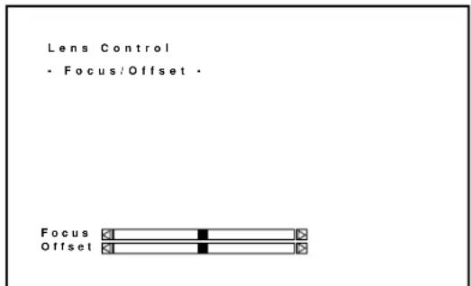
Allows you to adjust the focus and the vertical offset for your image.
You can also display the Lens Control adjustment screen directly by holding down the CTL button and then pressing the OPERATE button.
The CURSOR of button adjusts the focus.
The CURSOR or button adjusts the vertical offset.
Display Control
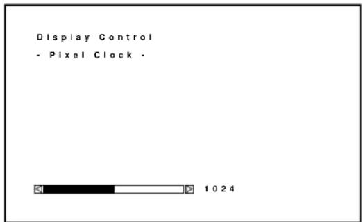
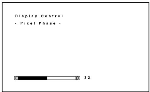
Enables you to fine tune the computer image or to remove any vertical banding that might appear by adjusting the clock frequencies, and to adjust the clock phase or to reduce video noise, dot interference or cross talk. This also allows you to pan or zoom in/out the image.
Use the CURSOR ☑ button to select the item you want and press the ENTER button.
Items to select
- Pixel Clock ---- Adjusts the clock frequencies to remove moire.
- Pixel Phase ---- Adjusts the clock phase to reduce video noise.
- Zoom/Pan----Magnifies or reduces the image. You also can pans the display when pressin with CTL.
-Display Control-
- Pixel Clock
- Pixel Phase
- Zoom/Pan
■ Pixel Clock / Pixel Phase
The CURSOR ☑ button increases video noise.
The CURSOR ☐ button decreases video noise.
■ Zoom/Pan
The CURSOR ☐ button enlarges the image or reduces the image.
The CURSOR ☑ button enlarges the image or reduces the image.
CTL+ □or △button pans the image.
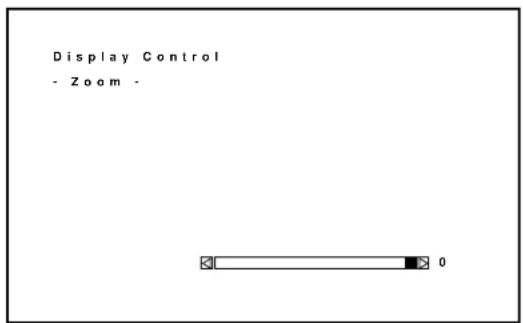
Image Control
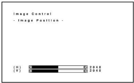
Enables you to adjust the image position and blanking.
Use the CURSOR 🔒 button to select the item you want to adjust and press the ENTER button.
Items to select
- Image Position ---- Adjusts the image position.
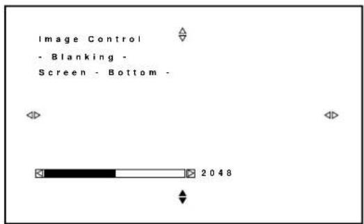
- Blanking---- Adjusts the screen area.
■ Image Position
Pressing the CURSOR ☑ moves the position of the picture left or right.
Pressing the CURSOR ☑ m ☑es the position of the picture up or down.
-Image Control-
- Image Position
- Blanking
■ Blanking
Press any one of the CURSOR buttons while press and hold CTL to select the position you want to adjust:
CTL+ △---- Top
CTL+ Right
CTL+ ☒---- Left
CTL+ ▽---- Bottom
Top and right ---- Pressing ▲r increases the adjustment values.
Pressing ▼ decreases the adjustment values.
Bottom and left ---- Pressing ☑ increases the adjustment values.
Pressing △r decreases the adjustment values.
Sound Control (only when used with the ISS-6020/ISS-6020G Switcher)
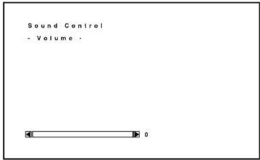
Provides access to control for your sound volume.
NOTE: This function works only with the ISS-6020/ISS-6020G Switcher.
The CURSOR

button
increases the volume.
The CURSOR

buwon
decreases the volume.
Closed Caption
Enables you to set several closed caption modes for text to be superimposed on the projection screen.
Use the CURSOR ☑ button to select the desired mode and press the ENTER button.
Items to select
• Caption 1-4 ---- Text is superimposed.
- Text 1-4 ----Text is displayed in full screen.
- Off ----Exits the selected Closed Caption mode.
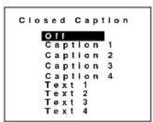
NOTE:
• The Closed Caption feature work with an NTSC 3.58 source only.
- Pressing ENTER executes store function. Switching to source other than NTSC3.58 source again.
Timer Setting
Enables you to program to turn on or off your projector automatically at a specified time. The two timer functions are available: On/Off Timer and Sleep Timer.
NOTE: When the On Timer is set and the projector is in standby, the two digit indicator flashes "00" to indicate that the On Timer is active.
Proceed as follows:
- Before setting On/Off Timer, maker sure that Date, Time Preset feature is set.
- Even after setting On/Off Timer, turning the projector on or off with the remote control is possible.
- There are two time display formats: 24-hour or AM/PM format. You can set either format in the "Date, Time Preset" in [Adjust - Set Option - Menu Mode].
User the CURSOR ☑ button to select "On/Off Timer" or "Sleep Timer".
Items to select
- On/Off Timer---Programs to turn on or off the power at a predetermined time.
- Sleep Timer---Programs to turn off the power at a predetermined time, up to two hours later in 30-minute increments.
To set the On/Off Timer:
1) Use the CURSOR button to select On/Off Timer and press ENTER to display the On/Off Timer menu.
2) Select a program number and press ENTER to display the On/Off Timer Setting menu.
3) Set the Week, Day, On-Time and Off-Time using the CURSOR buttons and INPUT buttons (1 thru 10). To cancel the on-time or off time, press NORMAL.
-Timer Setting-
- On/Off Timer
- Sleep Timer
![On/Off Timer Prg Week Day On Time Off Time 1 1 Week Mon 09:00 12:00 2 3 4 Every Mon-Fri 18:00 22:00 5 6 7 8 Execute Switch [Inactive ]](/content/2026/05/1042035/images/4d90df919220b6ea826bb38a0fafd3b8b9a43cdd88534bb36887a121e8b09d90.jpg)
![On-Off Timer Prg Wee On/Off Timer Setting Time 1 1 We Program 1 2 Week [1 Week ] 0 3 Day [Mon] 4 Ever 5 On Time [00:00] 6 Off Time [00:00] 7 Execute Entry Cancel Clear](/content/2026/05/1042035/images/e9fbf582d71887fd0ee50135f9a60b51ae2bcecada18471f6945f5e87cd03d48.jpg)
4) Select the Entry and press ENTER. This enables the On Timer or Off Timer function.
To cancel your data such as week, day, on/off time, select the Cancel and press ENTER.
To delete the setting data such as week, day and on/off time for the program number, select the Clear and press ENTER.
NOTE:
When setting On Timer during cooling the fan, the projector will turn on after the cooling has finished.
To set the Sleep Timer:
1) Use the CURSOR ☐ button to select the Sleep Timer and press ENTER to display the Sleep Timer menu.
2) Select the Set and press ENTER to drop the pull-down menu.
3) Select your desired time between 30 minutes and 2 hours in 30 minutes.
NOTE: "- : --" indicates the Sleep Timer will not be used.
To enable your settings:
Select "Active" in Execute Switch and press ENTER.

![On/Off Timer Prg Week Day On Time Off Time 1 1 Week Mon 09:00 12:00 2 3 4 Every Mon-Fri 18:00 22:00 5 6 7 8 Execute Switch [Inactive ]](/content/2026/05/1042035/images/840f6d2d0b2eeb93a22f9d944f86c3421bcedf5e5b7a7cd613f1f8dc6788a25a.jpg)
Adjusting and Setting (Adjustment)
Source Registry
On Source Registry
The projector uses a micro-processor to automatically read and distinguish between all video signals input at the same time. These signals are then used to make optimum adjustments for best image. Various parameters must be registered into the micro-processor beforehand to ensure the video signals are recognized and adjusted to optimum quality.
This function registers these video signals in the Source Select list and at the same time obtains the various parameters pertaining to these signals. Always access this mode first whenever inputting video signals for the first time so that you can register the video signals before making any adjustments. If the current input signal(s) has not been registered, the “New Signal” message is displayed on screen.
NOTE: If you have software which changes scanning mode due to the graphic board of your PC (such as VGA), it will be necessary to register signal entry for each scanning mode. This can be done using your PC by way of stopping the software in each scanning mode and performing a signal entry operation.
■ Source Registry
When connecting a signal for the first time, you need to register it into the projector's memory. You can copy the initial setting for the new signal from any other signal that has already been registered or use the factory preset setting.
To make the signal entry, proceed as follows:
① Press the ADJUST button.
• The Adjust menu is displayed.
② Use the CURSOR ☐ or ☑ button to highlight the “1.Source Registry” line and press ENTER.
- The Source Registry menu will be displayed.
- You can also select the Source Registry menu directly by pressing the INPUT "1" button.
-Adjustment-
1. Source Registry
- Amplitude
- White Balance
- Signal Level
- Uniformity
- Display Function
- Lamp Mode
- Set Option ▷
-Source Registry-
1. New Registry
- Registry Edit
Items to select
- New Entry ---- Registers a new signal.
- Registry Edit. - Changes setting various parameters of the registered signals.
③Use the CURSOR on button to highlight the "1.New Registry" line and press ENTER.
- The "1. Slot" menu is displayed. Then proceed as follows:
- Select slot.
- Select signal system.
- Set HDTV or not when selecting component signal.
- Input a user name.
- Select a location number for your registry.
To advance the next item, select Next and press ENTER. To return the previous item, select Prev and press ENTER. To cancel your registry, select Cancel.
1) To Select a Slot
You have two steps depending on whether you use your projector on standalone or with the ISS-6020 switcher(s).
NOTE: The setting INPUT TERMINAL cannot be done to the current projected signal.
When using the projector in stand alone application: Use the CURSOR button to select one of the three slots, and press ENTER.
Items to select
- INPUT A ---- Standard
- INPUT B ---- Optional board
- INPUT C ---- Optional board
When using with a single Switcher ISS-6020/ISS-6020G:
Use the CURSOR ☑ button to select the input slot number of the Switcher and press ENTER.
- Input slot numbers are from 1 through 10.
- The “4. User Name” screen will be displayed when you finish entering the slot number.
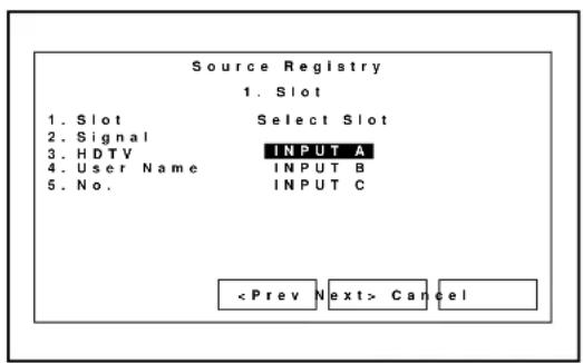
![Source Registry 1. Slot 1. Slot Select Slot 2. Signal 3. HDTV Master Slave 4. User Name [Slot1 ▼] [Slot1 ▼] 5. No. Cancel](/content/2026/05/1042035/images/9f2cba2eab36f9dbf7446e2da20af96d9b62e11f2e02e58321bb38c5c2b57553.jpg)
When using with two or more ISS-6020/ISS-6020G switchers:
Use the CURSOR or button to select the input slot number of the master Switcher and press ENTER. Then select the slot number of the slave Switcher and press ENTER.
- The “MASTER” menu will be displayed when the slot number of the master Switcher is selected.
- The “SLAVE” menu will be displayed when the slot number of the slave Switcher is selected.
- The “4. User Name” screen will be displayed when you finish entering the slot number.
2) To Select Signal System
Select your desired signal system.
Items to select
- RGB ---- Selects the RGB input signal of this projector
• C-Video ---- Selects the VIDEO input signal of this projector - S-Video ---- Selects the S-VIDEO input signal of this projector.
- COMPONENT ---- Selects the component input signal of this projector.
3) To Set HDTV or not When Selecting Component Signal.
When you select COMPONENT, you are asked if the component is HDTV or not.
Select Yes or No according to your component source.
4) To Input a User Name.
Input the source name by selecting one character at a time with the INPUT buttons 1 through 10 and by moving the cursor with the CURSOR button. After finishing the selection of the characters, press ENTER.
- Up to eight characters can be selected.
- Eight characters are assigned to one INPUT button.
- Whenever the INPUT button is pressed, characters will be rotated.
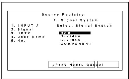
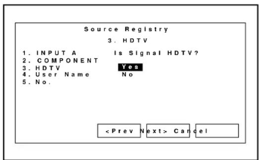
![Source Registry 4. User Name 1. INPUT A Input User Name 2. COMPONENT 3. HDTV Mode [ ] 4. User Name 5. No. Cancel](/content/2026/05/1042035/images/3b503a40fb6d30847d94dbfd3b0ce512a68fd0cb8ca8c444c4b9704909fda737.jpg)
For example: A → B → C → 1 → A .....
- When pressing the INPUT button while holding down the CTL button, another group of characters will be rotated.
For example: a → b → c → ! → a .....
- The characters corresponding to these INPUT buttons are as follows:
When using With CTL
INPUT 1 A, B, C, and 1 a, b, c, and !
INPUT 2 D, E, F, and 2 d, e, f, and “\par INPUT 3 G, H, I, and 3 g, h, i, and #
INPUT 4 J, K, L, and 4 j, k, l, and \$
INPUT 5 M, N, O, and 5 m, n, o, and %
INPUT 6 P, Q, R, and 6 p, q, r, and &
INPUT 7 S, T, U, and 7 s, t, u, and '\par INPUT 8 V, W, X, and 8 v, w, x, and (
INPUT 9 Y, Z, ?, and 9 y, z, /, and )
INPUT 10 *, , , and 0 ; , +, and -
If you have made an error in the input of a character, use the CURSOR button and enter the correct letter or number.
To delete one character, move the CURSOR button to the character to be deleted and then press the NORMAL button.
To delete all the entered name, hold down the CTL button then press NORMAL.
5) To Select a Registry Number.
Select the number location where you want to register the signal and press ENTER.
The “Do you want to register ?” message is displayed. If yes, press ENTER.
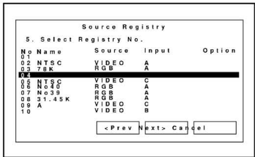
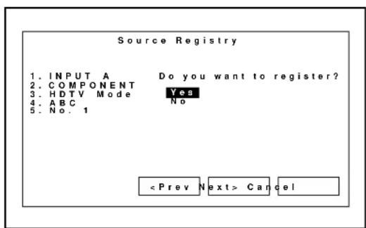
■ Registry Edit
This feature allows you to change various parameters of the source on the selected line. This can be done to the current projected signal as well as not projected source.
To edit the registered signal, proceed as follows:
1) Press the ADJUST button.
• The Adjust menu is displayed.
2) Use the CURSOR ☑ button to highlight the “1.Source Registry” line and press ENTER.
- The Source Registry menu will be displayed.
- You can also select the Source Registry menu directly by pressing the INPUT "1" button.
Items to select
- New Entry---- Registers a new signal.
- Registry Edit-------- Changes setting various parameters of the registered signals.
3) Use the CURSOR ☑ button to highlight the “2. Registry Edit” line and press ENTER.
- The “Registry Edit” screen is displayed.
4) Use the CURSOR ☑ button to highlight the registered signal and press ENTER.
- The “Edit Command” menu is displayed. Then proceed as follows:
* Cut Enables you to remove a selected signal from the list and place it on the “clipboard” in the projector.
* Copy Enables you to copy a selected signal from the list and place it on the “clipboard” in the projector.
* Paste Enables you to paste the signal placed on the “clipboard” to any other line of the list. To do this, select “Paste” and then select the line number you want to paste to. Last press ENTER.
* Information Enables you to set a various parameters. When “Information is selected, the Source Information screen is displayed. Select an item and press ENTER.
5) When setting is completed, press END.
NOE: The contents will leave the "clipboard" when you press END.
Edit Command
Cut
Copy
Paste
Information
Amplitude
Enables you to adjust the horizontal and vertical amplitude of the image.
NOTE: Normally use the normal value.
Use the CURSOR ☑ to adjust the horizontal amplitude.
Use the CURSOR or to adjust the vertical amplitude.
When the amplitude adjusting is completed, press the END button.
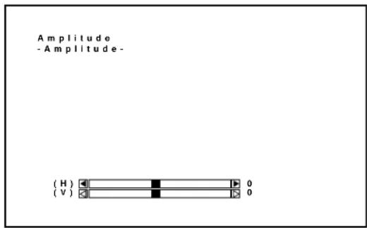
White Balance
Enables you to adjust the white balance of the image.
Items to select
- White/Red-Blue ----Adjust the white level for the red or blue.
- Black/Red-Blue ----Adjust the black level for the red or blue.
Use the CURSOR or to adjust the level of each item.
Use the CURSOR or to select an item.
When the white balance adjusting is completed, press the END button.

bar
| Category | Red | Black | |---|---|---| | White | 255 | 0 | | Blue | 64 | 128 |Signal Level
Enables you to adjust the signal level.
NOTE: You can directly access the Signal Level by pressing the SIGNAL LEVEL button on the remote control.
Use the CURSOR ☑ to adjust the level of each item.
Use the CURSOR or to select an item.
When the signal level adjusting is completed, press the END button.
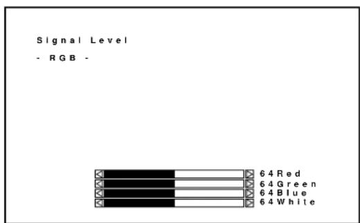
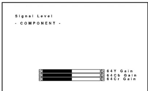
Uniformity
Enables you to adjust the white uniformity and edge blending.
The white uniformity feature allows you to adjust color balance on the left and right side of the screen; the edge-blending feature allows you to adjust the brightness on the area which two images projected from the two projectors are overlapped.
To Adjust White Uniformity
1) Press R or B button while pressing and holding CTL to select the color you want to adjust. Note that Green is not available.
2) Move the cursor to the area you want to adjust using CURSOR button while pressing and holding CTL.
- CTL + ☐ moves the cursor to the right.
- CTL + ☑ moves the cursor to the left.
- CTL + moves the cursor up.
- CTL + moves the cursor down.
3) Use the CURSOR buttons to adjust the white uniformity.
- Pressing or increases the level.
- Pressing or decreases the level.
4) Repeat from the step 1 for the other color.
1) Press the CURSOR buttons while pressing and holding CTL to select the area you want to adjust.
- CTL + selects the top
- CTL + Selects the bottom
- CTL + ☑ selects the right
- CTL + selects the left
2) Use the CURSOR ☐ button to select "DATA" or "POS.".
- "DATA" ---- Adjusts the level
- “POS.” ---- Adjusts the position
3) Use the CURSOR ☑ or ☒ button to adjust the edge blending.
- When "DATA" is selected:
Pressing □ increases the level.
Pressing □ decreases the level.
- When "POS." is selected:
Pressing ☐ moves the position to the top or the right.
Pressing ☑ moves the position to the bottom or the left.
To exit the Uniformity, press END.
-Uniformity-
-
White Uniformity
-
Edge Blending
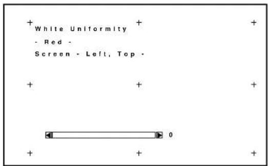
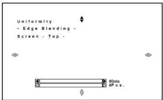
Display Function
Enables you to adjust various items such as the input signal size, output signal size, output position, interlace mode and sync protect if the image is not displayed correctly. Normally you do not need to set these items.
1) Input Signal Size
Adjusts the size of input signal.
The CURSOR button adjusts the horizontal size.
The CURSOR ☐ button adjusts the vertical size.
2) Output Signal Size
Adjusts the size of output picture.
The CURSOR ☑ button adjusts the horizontal size.
The CURSOR ▲ button adjusts the vertical size.
3) Output Position
Adjusts the display position of output picture.
The CURSOR ☑ button adjusts the horizontal position.
The CURSOR ☑ button adjusts the vertical position.
4) Interlace Mode
Select the appropriate mode for an interlace signal viewing the image. Normally select the mode preset at the factory.
5) Sync Protect
After selecting ON, adjust the bending of the top of the screen.
Normally select OFF.
To adjust, use the CURSOR ☑ to adjust the level viewing the screen.
To switch the top or the bottom, press the CURSOR ☑ button.
6) PLL Gain
Adjust so that the clock signal is stabilized.
Normally use at the factory setting value.
7) Video Filter
Normally use at the factory setting value.
Input of a high resolution signal such as an XGA or SXGA can cause white characters to be tinted with color. If this happens, set the filter switch to ON and then adjust the frequency by using the CURSOR button.
-Display Function-
- Input Signal Size
- Output Signal Size
- Output Position
- Interlance Mode
- Sync Protect
- PLL Gain
- Video Filter
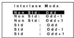
Display Function
- Sync Protect -

Display Function
- PLL Gain -

Display Function
- Video Filter -

Lamp Mode
Enables you to adjust the brightness of the lamp.
Items to select
- Normal ---- Normally select this mode.
- High Bright ---- Select this mode to increase the brightness of the lamp.
NOTE: The High Bright mode shortens the lamp life. Be sure to use this mode at temperature 95^ F ( 35^ C) or less.
Lamp Power
Normal
High-Bright
Set Option
Passcode
■ Entering Passcode
To prevent any unauthorized operation or mis-adjustment, the projector is equipped with a passcode option. If your passcode has not been entered correctly, the “Adjustment” menu will not be displayed. When the ADJUST button is pressed, and no passcode has been entered, the “Passcode?” screen is displayed. Enter your passcode.
To do this, proceed as follows:
① Press the ADJUST button.
- The “Passcode?” screen is displayed.
② Enter the four digit passcode you have already registered by using the "1" through "10" buttons.
1) Each time you press the INPUT button, an asterisk appears under the "Passcode?" message.
2) After you have finished entering the four digit passcode, press ENTER.
NOTE: If you have made an error, press the NORMAL button to delete the asterisk “*”. Then re-enter the correct passcode. To delete all the entered digits, hold down the CTL button then press the NORMAL button.
3) If the entered passcode is correct, the "ADJUST" menu is displayed.
NOTE: If the passcode is not correct, the "Warning Different Passcode!!" message is displayed and you are required to enter the correct passcode.
③ Proceed to each adjustment and setting.
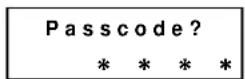
■ Registering Passcode
When the projector is shipped from the factory, no passcode is registered. If you want to use the passcode option, you must register a passcode.
To register a new passcode, proceed as follows:
① Press the ADJUST button.
- The "Adjustment" menu will be displayed.
② Use the CURSOR or button to highlight the "8.Set Option" menu. Press ENTER to display the Set Option menu.
③ Use the CURSOR or button to highlight the "1.Passcode" line. Press ENTER to display the "Passcode Setting" menu.
④ Use the CURSOR or button to select "Entry". Press ENTER to display the "New Passcode?" menu.
⑤ Enter a four digit passcode using the "1" through "10" buttons.
1) Each time you press the INPUT button, an asterisk will appear next to the "New Passcode?" message.
NOTE: "0000" and "9999" cannot be used as a passcode.
2) Once you have finished entering your four digit passcode, press ENTER to store the code.
NOTE: If you have made an error, press the NORMAL button to delete the asterisk “*”. Then re-enter the correct passcode. To delete all the entered digits, hold down the CTL button then press the NORMAL button.
3) If the passcode has been entered correctly, the "Confirm New Passcode?" menu will be displayed.
NOTE: If the passcode is not entered correctly, the "Warning Passcode!!" message will be displayed. You will be required to enter the passcode correctly.
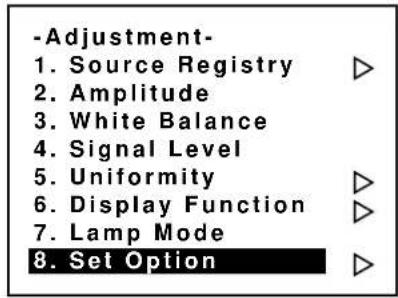
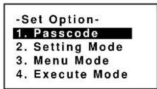
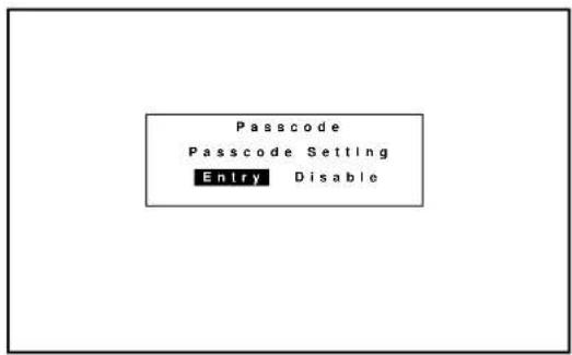
![Passcode Passcode Setting New Passcode [****]](/content/2026/05/1042035/images/2aa29d721b59adbc37f4e94d637827c21e27ec6b74fc3fcd6e342aae2f171024.jpg)
3. OPERATION
⑥ Enter the new passcode again.
1) Each time you press the INPUT button, an asterisk will appear next to the "Confirm New Passcode?" message.
2) Once you have finished entering the new four digit passcode, press ENTER.
NOTE: If you have made an error, press the NORMAL button to delete the asterisk “*”. Then re-enter the correct passcode. To delete all the entered digits, hold down the CTL button then press the NORMAL button.
3) If the entered passcode is correct, the "Change Passcode Complete!!" message will be displayed.
NOTE: If the passcode is not correct, the "Warning Different Passcode!!" message will be displayed. You are required to enter the new passcode correctly.
The new passcode has been registered.
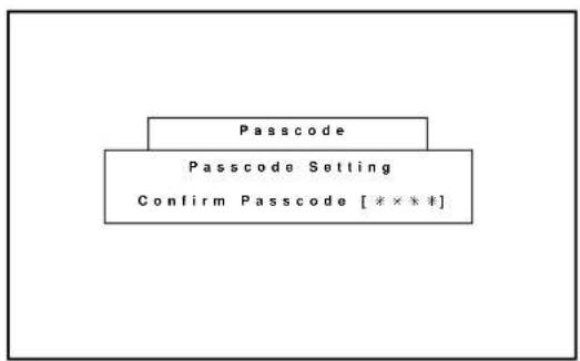
flowchart
graph TD
    A["Passcode"] --> B["Passcode Setting"]
    B --> C["Confirm Passcode [** * * *"]]
    C --> D["End"]
■ Changing Your Passcode
To change your passcode, proceed as follows:
① Press the ADJUST button.
- The "Passcode?" screen will be displayed.
② Enter the four digit current passcode using the “1” through “10” buttons. Press ENTER.
- The “Adjustment” menu will be displayed.
③ Use the CURSOR or button to highlight the "8. Set Option" menu. Press ENTER to display the "Set Option" menu.
④ Use the CURSOR or button to select "1. Passcode". Press ENTER to display the "Passcode Setting" menu.
⑤ Use the CURSOR or button to select "Entry". PressENTER to display the "Current Passcode?" menu.
⑥ Enter the four digit passcode (the current passcode) using the “1” through “10” buttons.
1) Each time you press the INPUT button, an asterisk will appear next to the "Current Passcode?" message.
2) Once you have finished entering the four digit passcode, press ENTER.
NOTE: If you have made an error, press the NORMAL button to delete the asterisk “*”. Then re-enter the correct passcode. To delete all the entered digits, hold down the CTL button then press the NORMAL button.
3) If the entered passcode is correct, the "New Passcode?" screen will be displayed.
NOTE: If the passcode is not correct, the "Warning Different Passcode!!" message is displayed. You will be required to enter the correct current passcode.
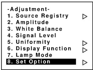
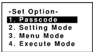
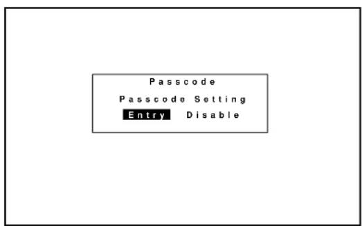
![Passcode Passcode Setting Current Passcode [****]](/content/2026/05/1042035/images/35d17bf0f68bd3c03789c0eef31dd4ab6c7ebc757c8fc2a4df3db54cf62020c1.jpg)
![Passcode Passcode Setting New Passcode [****]](/content/2026/05/1042035/images/067d65139e51cb5ad97cef954d650bf95bf4f203976cf126810eddaa4033ef33.jpg)
⑦ Enter a new passcode using the “1” through “10” buttons.
1) Each time you press the INPUT button, an asterisk will appear next to the "New Passcode?" message.
2) Once you have finished entering the four digit new passcode, press ENTER.
NOTE: If you have made an error, press the NORMAL button to delete the asterisk “*”. Then re-enter the correct passcode. To delete all the entered digits, hold down the CTL button then press the NORMAL button.
3) If the passcode has been entered correctly, the “Confirm New Passcode?” menu will be displayed.
NOTE: If the passcode is not entered correctly, the "Warning Different Passcode!!" message will be displayed. You are required to enter the new passcode correctly.
⑧ Enter the new passcode again using the “1” through “10” buttons.
1) Each time you press the INPUT button, an asterisk will appear under the "Confirm New Passcode?" message.
2) Once you have finished entering the four digit new passcode, press ENTER.
NOTE: If you have made an error, press the NORMAL button to delete the asterisk “*”. Then re-enter the correct passcode. To delete all the entered digits, hold down the CTL button then press the NORMAL button.
3) If the entered passcode is correct, the “Change Passcode Complete!!” message is displayed.
NOTE: If the passcode is not entered correctly, the "Warning Different Passcode!!" message is displayed. You will be required to enter the new passcode correctly.
The passcode has been changed to another.
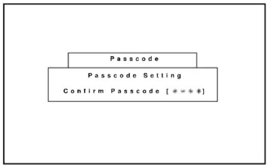
flowchart
graph TD
    A["Passcode"] --> B["Passcode Setting"]
    B --> C["Confirm Passcode [****"]]
    C --> D["End"]
■ Canceling Your Passcode
To cancel the passcode, proceed as follows:
① Press the ADJUST button and then enter your passcode.
- The “Passcode?” screen will be displayed.
② Enter the four digit current passcode using the "1" through "10" buttons and then press ENTER.
- The “Adjustment” menu will be displayed.
③ Use the CURSOR or button to highlight "8. Set Option". Press the ENTER button to display the "Set Option" menu.
④ Use the CURSOR or button to highlight "1. Passcode" line. Press ENTER to display the "Passcode Setting" menu.
⑤ Use the CURSOR or □ton to select “Disable”. Press ENTER to display the “Passcode Disable?” menu. Select “Yes” and press ENTER.
- The “Current Passcode” screen will be displayed.
⑥ Enter the four digit passcode (the current passcode) using the “1” through “10” buttons.
1) Each time you press the INPUT button, an asterisk will appear next to the "Current Passcode?" message.
2) Once you have finished entering the four digit passcode, press ENTER.
NOTE: If you have made an error, press the NORMAL button to delete the asterisk “*”. Then re-enter the correct passcode. To delete all the entered digits, hold down the CTL button then press the NORMAL button.
3) If the entered passcode is correct, the "Passcode Disable?" menu will be displayed.
NOTE: If the passcode is not correct, the "Warning Different Passcode!!" message will be displayed. You will be required to enter your correct passcode.
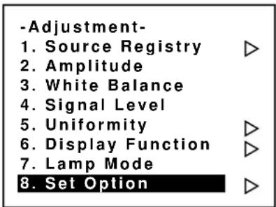
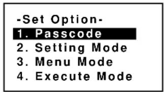
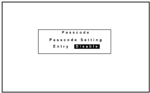
![Passcode Passcode Setting Current Passcode [****]](/content/2026/05/1042035/images/a4e3c84706b083015c16fc238a565f6406923d6949927edeb87bfbd21760734a.jpg)
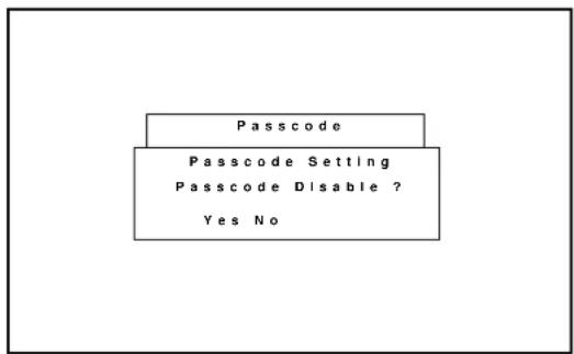
flowchart
graph TD
    A["Passcode"] --> B["Passcode Setting"]
    B --> C["Passcode Disable ?"]
    C --> D["Yes No"]
⑦ Use the CURSOR or button to select Yes and then press ENTER.
Items to select
- Yes ---- When selecting "Yes", the current passcode will be canceled. You will not be required to re-enter your passcode when you press the ADJUST button to re-enter the ADJUST mode.
- No ---- When selecting "No", the current passcode will remain in effect.
Your passcode has been cancelled.
Setting Mode
Enables you to set various items.
To do, follow the steps below.
- Press the ADJUST button to display the Adjustment menu.
- Use the CURSOR ☑ button to select "8. Set Option" menu. Press ENTER.
- Use the CURSOR or button to select "2. Setting Mode" menu. Press ENTER.
Proceed to the following steps.
■ PJ Orientation
This feature allows you to set the installation type according to the projection configuration.
① Use the CURSOR or button to select the “PJ ORIENTATION” item, then press ENTER to display the “PJ ORIENTATION” menu.
② Use the CURSOR or button to select one of the four projector installation types and press ENTER.
Items to select
- CEILING/REAR .... Ceiling mounting type and rear projection
- FLOOR/REAR..... Desk top type and rear projection
- CEILING/FRONT .. Ceiling mounting type and front projection
- FLOOR/FRONT..... Desk top type and front projection
-Setting Mode-
1. PJ Orientation
- Default Source Select
- S-Video Mode Select
- Video System Select
- Auto Data Store
- Option Terminal Speed
- Uniformity Switching
![Setting Mode PJ Orientation [Ceiling/Front] Default Mode Select Default INPUT-A S-Video S-Video Mode Select [S2] Video System Select Manual NTSC3.58 Auto Data Store [Disable] Option Terminal Speed [38400 BPS] Uniformity White [Disable] Edge Blend. [Disable]](/content/2026/05/1042035/images/458bb93d88e217e0e3d5f000ee2887d3e01d60d6b1637cb3fed7c5b5dac47067.jpg)
Floor / Rear
Ceiling / Front
Floor / Front
Ceiling / Rear
■ Default Source Select
You can set the projector to default to any one of its inputs each time the projector is turned on.
Proceed as follows:
① Use the CURSOR or button to select the "Default Source Select" item, then press ENTER to display the "Default Source Select" menu.
-Setting Mode-
-
PJ Orientation
-
Default Source Select
-
S-Video Mode Select
- Video System Select
- Auto Data Store
- Option Terminal Speed
- Uniformity Switching
![Setting Mode PJ Orientation [Ceiling/Front ▼] Default Mode Select Default INPUT-A S-Video S-Video Mode Select [S2 ▼] Video System Select Manual NTSC3.58 Auto Data Store [Disable ▼] Option Terminal Speed [38400 BPS ▼] Uniformity White [Disable ▼] Edge Blend. [Disable ▼]](/content/2026/05/1042035/images/7f99ff67e1dc36a766034cf5b9d74e7dd7d6d167c995e26678fc752b25bc31d5.jpg)
② Use the CURSOR or button to select either "Default" or "Last" and press ENTER.
- Selecting "LAST" completes setting.
- Selecting "DEFAULT" displays the "Default input" screen.
Items to select
- DEFAULT. Displays the same source input every time the projector is started up.
- LAST ...... Sets the projector to default to the previous last active input each time the projector is turned on.
Note: An input must be active for a minimum of 10 minutes before it is recognized as the last active signal.
![Setting Mode P/O Default Source Select De Default Source [Default ▼] Slot [Input-A ▼] Signal [COMPO. HDTV] ▼] S-V Vid OK Cancel NTSC3.58 Auto Data Store [Default ▼] Option Terminal Speed [38400 Bps ▼]](/content/2026/05/1042035/images/1cdfba7ca7e94bf68c659caf944644b37ba3c05f00656a6975473d4fc31873ee.jpg)
③ Use the CURSOR or button to select an input and then press the ENTER button.
When used in stand alone operation:
The default input screen will be displayed.
Use the CURSOR ☑ button to select an input and press ENTER.
When used with a single Switcher:
The “MASTER” slot menu will be displayed.
Use the CURSOR button to select the desired slot number "1" through "10(0)" and then press ENTER.
When used with two or more Switchers:
The “MASTER” and “SLAVE” slot number menu will be displayed.
Use the CURSOR button to select the master slot number first and then select the slave slot number "1" through "10(0)". Press ENTER.
④ Use the CURSOR or button to select a signal and press ENTER button.
⑤ Press OK to complete the setting.
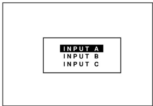
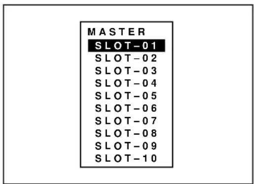
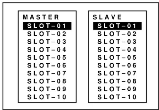
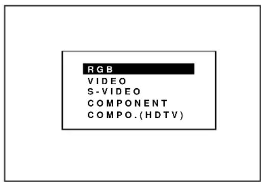
■ S-Video Mode Select
This function is used to select the S-video signal detection mode.
This allows identifying of the S-video signals with different aspect ratio: squeeze or full mode(16 : 9) and letter box (4 : 3) signals.
To set, proceed as follows:
① Use the CURSOR or button to select the "S-Video Mode Select" item, then press ENTER to display the "S-Video Mode Select" menu.
② Use the CURSOR or button to select one of the three items: S2, S1, and OFF, and then press ENTER.
Items to select
S2 ...... Identifies squeeze and letter box signals.
S1 ...... Identifies a squeeze signal only.
OFF ...... Does not identify any S-video signal.
NOTE :
- The input signal must be compatible with the S2/S1 MODE standard.
Refer to the user manual included with the connected equipment for more information. - The identification function may not work correctly with a non-compatible signal. If this happens, select "OFF" from the "S-VIDEO MODE SELECT" menu.
-Setting Mode-
-
PJ Orientation
-
Default Source Select
3. S-Video Mode Select
- Video System Select
- Auto Data Store
- Option Terminal Speed
- Uniformity Switching
Setting Mode
PJ Orientation
Default Mode Select
[Ceiling/Front
Default
INPUT-A
S-Video Mode Select Video System Select
Auto Data Store
Option Terminal Speed
Uniformity White
Edge Blend.

Manual
NTSC3.58
[Disable
[38400 BPS
[Disable
[Disable

[▼]
1
▼
[▼]
S-Video Mode Select
S2
S 1
OFF
■ Video System Select
This function is used to select the NTSC 3.58, NTSC 4.43, PAL or SECAM video standard.
To select any one of the video standards, proceed as follows:
① Use the CURSOR or bMton to select the “Video System Select” item, then press ENTER to display the “Video System Select” menu.
② Use the CURSOR or button to select either "Auto" or a video standard manually and then press ENTER.
When selecting "AUTO"
Video Modes
• NTSC3.58 ..... Indicates the NTSC3.58 video standard
• NTSC4.43 ..... Indicates the NTSC4.43 video standard
- PAL ....Indicates the PAL video standard
- SECAM ...... Indicates the SECAM video standard
- Select "Auto" in normal operation.
- Select a video standard manually when connecting to poor quality signal or non-standard signals such as video games.
NOTE: The projector may not function correctly with a monochrome signals in the Auto mode.
-Setting Mode-
- PJ Orientation
- Default Source Select
- S-Video Mode Select
4. Video System Select
- Auto Data Store
- Option Terminal Speed
- Uniformity Switching
![Setting Mode PJ Orientation [Ceiling/Front] Default Mode Select Default INPUT-A S-Video S-Video Mode Select [S2] Video System Select Manual NTSC3.58 Auto Data Store [Disable] Option Terminal Speed [38400 BPS] Uniformity White [Disable] Edge Blend. [Disable]](/content/2026/05/1042035/images/3492c9bd4f42302be6a375b805bae1196725df0c1edec5ffec15f5778fe519d4.jpg)
![Setting Mode P | Orien Default Video System Select AUTO NTSC3.58 NTSC4.43 PAL SECAM Auto Dat Option Terminal Speed [38400 Bps] ont -A eo 2 ? ? ? ? 3.58 e ▼ ▼](/content/2026/05/1042035/images/ebd4ac9d47e0081386672cda79b9e6b46592a7218805442308bb841f4a193d91.jpg)
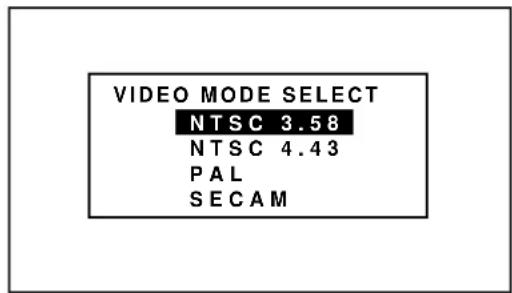
■ Auto Data Store
This feature allows you to select two ways to store settings; automatically and manually.
After “Enable” is selected in the Auto Data Store menu, all projector settings are stored in the projector's memory automatically. To set this feature, proceed as follows:
① Use the CURSOR ☐ or ☑ button to select the “Auto Data Store” item on Page 2, then press ENTER to display the “Auto Data Store” menu.
② Use the CURSOR or button to select either "Disable" or "Enable" and then press ENTER.
Items to select
- Disable .... Projector does not store the settings automatically.
- Enable ..... Projector stores the settings automatically.
Automatic storing data is done when any one of the following procedures is performed:
- Pressing the END button several times returns the adjustment screen to the source screen.
• One input is switched to another.
• The projector is turned off. - Every 10 minutes.
NOTE: After "Disable" is selected in the Auto Data Store menu, the settings will not be stored in the memory unless you select "Yes" in the "Store ?" menu.
-Setting Mode-
- PJ Orientation
- Default Source Select
- S-Video Mode Select
- Video System Select
5. Auto Data Store
-
Option Terminal Speed
-
Uniformity Switching
Setting Mode
PJ Orientation [Ceiling/Front ▼]
Default Mode Select
Default INPUT-A S-Video
S-Video Mode Select Video System Select
[ S 2 ▼ ]
Manual NTSC3.58
Auto Data Store Option Terminal Speed
[Disable]
Uniformity White
[38400 BPS ▼] [Disable ▼] [Disable ▼]
Auto Data Store
Disable
Enable
■ Option Terminal Speed
This feature allows you to set baud rate of the OPTION terminal from 4800 to 38400 bps.
NOTE:
- The baud rate of the OPTION terminal defaults to 38400 bps at the factory.
- Make sure that the baud rate of the OPTION terminal matches that of operating of the connected equipment.
To change the baud rate of the OPTION terminal, proceed as follows:
① Use the CURSOR or button to select the “Option Terminal Speed” item, then press ENTER to display the “Option Term Boad Rate” menu.
② Use the CURSOR or button to select the baud rate from 4800 to 38400 bps and press ENTER.
-Setting Mode-
- PJ Orientation
- Default Source Select
- S-Video Mode Select
- Video System Select
- Auto Data Store
6. Option Terminal Speed
7. Uniformity Switching
![Setting Mode PJ Orientation [Ceiling/Front ▼] Default Mode Select Default INPUT-A S-Video S-Video Mode Select [S2 ▼] Video System Select Manual NTSC3.58 Auto Data Store [Disable ▼] Option Terminal Speed [B8400 BPS ▼] Uniformity White [Disable ▼] Edge Blend. [Disable ▼]](/content/2026/05/1042035/images/6b9149f5496da01d975c37d3abb377b4bcac67b456e82af60c5b4ea89209ab7c.jpg)
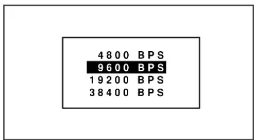
■ Uniformity Switching
Enables you to enable or dasable the uniformity white and edge blending features.
① Use the CURSOR☑ or button to select the “Uniformity Switching” item, then press ENTER.
② Use the CURSOR or bMton to select the “White Uniformity or Edge Blend.” item, and select Disable or Enable, then ENTER.
-Setting Mode-
- PJ Orientation
- Default Source Select
- S-Video Mode Select
- Video System Select
- Auto Data Store
- Option Terminal Speed
- Uniformity Switching
![Setting Mode PJ Orientation [Ceiling/Front ▼] Default Mode Select Default INPUT-A S-Video S-Video Mode Select [S2 ▼] Video System Select Manual NTSC3.58 Auto Data Store [Disable ▼] Option Terminal Speed [38400 BPS ▼] Uniformity White [Disable ▼] Edge Blend. [Disable ▼]](/content/2026/05/1042035/images/fa68984003bc73f4aa68252151325d481eb41a424a037db478f4e1aacdc16731.jpg)
Menu Mode
Enables you to set various items for on-screen display. To do, follow the steps below.
- Press the ADJUST button to display the Adjustment menu.
- Use the CURSOR ☑ button to select "8. Set Option" menu. Press ENTER.
- Use the CURSOR button to select "3. Menu Mode" menu. Press ENTER.
Proceed to the following steps.
This feature allows you to display the items on the top of the screen: date, time, input signal, source name, address, and new signal.
■ Message Time
There are two modes of operations for the on-screen display. With AUTO mode, the on-screen display will automatically switch off after three through ten seconds. In the MANUAL mode, the display must be manually turned off with the DISPLAY button on the full function remote control each time it appears.
NOTE: Pressing DISPLAY with CTL will select the non on-screen mode; pressing DISPLAY with CTL again will cancel this mode. Even if the on-screen display may be turned off with CTL and DISPLAY, any adjustment will still change the projector's memory settings.
Proceed as follows:
① Use the CURSOR or button to highlight the "Message Time" item.
Press ENTER to display the "Message Time" menu.
-Menu Mode-
-
Message Time
-
Date, Time Preset
-
Display Item Set
![Menu Mode Message Time [Auto 10 Sec] Date, Time Preset Jan/DD/YYYY Display Item Set HH:MM:SS Date [Off ] Time [Off] Input Signal [Off] Soutce Name [Off] Address [Off] New Signal [Off]](/content/2026/05/1042035/images/d69d236fdea140c98785c15fcb241d6de5b7fdc92e939c38c6262ed810fd1b2c.jpg)
② Use the CURSOR or button to select either "Auto" or "Manual" and press ENTER.
Items to select
- Auto...... The on-screen menu display appears when the buttons on the remote control, or the controls on the rear panel are pressed. The on-screen display will turn off at a preselected time.
The OFF TIME is specified in seconds up to a maximum of 30 seconds.
Select your desired time (3-30 seconds) from the OFF TIME menu. - Manual .... The on-screen menu display appears when the buttons on the remote control, or the controls on the rear panel are pressed. The display will be turned on and off whenever the DISPLAY button is pressed. If no button operation is made for 20 minutes or more, the on-screen message will automatically turn off.
Manual
Auto 3 sec
Auto 10 sec
Auto 30 sec
■ Date, Time Preset
The current year, month, date and time are displayed on the top of the screen.
Proceed as follows:
① Use the CURSOR or button to highlight the "Date, Time, Preset" item. Press ENTER to display the "Date, Time Preset" menu.
② Use the CURSOR or button to select any one of the two items: Date, and Time.
③ Type the date and time. Then press OK.
-Menu Mode-
- Message Time
- Date, Time Preset
- Display Item Set
![Menu Mode Message Time [Auto 10 Sec] Date, Time Preset Jan/DD/YYYY HH:MM:SS Display Item Set Date [Off ] Time [Off] Input Signal [Off] Soutce Name [Off] Address [Off] New Signal [Off]](/content/2026/05/1042035/images/47d83337b332be5ae309440e4bb88d529087f5d84f510941aace567a8e06aeea.jpg)
![Menu Mode Message Date, Time Preset Date MM/DD/YYYY 12/15/1997 Off (Mon) Time HH/MM/SS [20:30:00] OK Cancel Address [Off] New Signal [Off]](/content/2026/05/1042035/images/e91bf05862ff2fe49ce8606d415a5a794682f9d1f2a5b45bd6e30c435deaf4ea.jpg)
■ Display Item Set
This feature allows you to display the items: date, time, input signal, source name, address, and new signal on the top of the screen.
① Use the CURSOR or button to highlight the "Display Item Set" menu. Press ENTER.
② Use the CURSOR or 80tons to select on or off and press ENTER.
-Menu Mode-
-
Message Time
-
Date, Time Preset
-
Display Item Set
![Menu Mode Message Time [Auto 10 Sec ▼] Date, Time Preset Jan/DD/YYYY HH:MM:SS Display Item Set Date [ ] ▼ Time [Off ▼] Input Signal [Off ▼] Soutce Name [Off ▼] Address [Off ▼] New Signal [Off ▼]](/content/2026/05/1042035/images/070f37bcc62e9845cf78a18142749c48171cc76accd1da9577364bc2e30abadb.jpg)
Execute Mode
Enables you to select connecting with the switcher ISS-6020 and view the projector address on the screen.
To do, follow the steps below.
- Press the ADJUST button to display the Adjustment menu.
- Use the CURSOR button to select "8. Set Option" menu. Press ENTER.
- Use the CURSOR button to select "4. Execute Mode" menu. Press ENTER.
Proceed to the following steps.
■ Connect Condition
This setting explains how the projector is used with the ISS-6020/ISS-6020G Switcher.
① Use the CURSOR or button to select the “1. Connect Condition” item, then press ENTER to display the ““1. Connect Condition” menu.
② Use the CURSOR or button to select your desired connection condition of Switcher and press ENTER.
- The “Re-Start ?” prompt is displayed after setting of the connection condition is modified from the current status to your desired condition.
Items to select
- Stand Alone ......The projector used in stand alone operation.
- SW 1 Level ...... The projector used with one Switcher.
- SW 2 Level ...... The projector used with two or more Switchers.
③ Use the CURSOR or button to select either "Yes" or "No" and press ENTER.
Items to select
- Yes ...... Restart the projector.
- No ...... Does not restart the projector.
NOTE: The selected connection condition becomes effective only after the projector is restarted.
-Execute Mode-
-
Connect Condition
-
PJ Address
Execute Mode
Connect Condition PJ Address
[Standalone ▼] [01] (01-64)
Connect Condition
Stand Alone
SW1 Level
SW2 Level
Re - Start?
Yes No
■ PJ Address
Each projector needs its own unique address in the case of a serial connection of projectors. Up to 64 addresses can be set.
Proceed as follows:
① Use the CURSOR or button to highlight the "2/PJ Address" line. Press ENTER to display the "Address" menu.
② Enter the address number using the INPUT button and press ENTER.
- If you have made a mistake, press END to return to the “OPTION” menu, then start again.
NOTE: Enter the address number "01" when only one projector is used.
-Execute Mode-
-
Connect Condition
-
PJ Address
![Execute Mode Connect Condition [SlandAlone ▼] PJ Address [01] (01·64)](/content/2026/05/1042035/images/14d334e8a4b7c8f6b01adf3a2e4a1fcbed11db6f040363eb03b258a38ebee8d5.jpg)
■ Addressing the Remote Control Unit
When changing the projector address, ensure that the projector address respond to the remote control address, otherwise you cannot operate the projector using the remote control.
To specify the remote control address, proceed as follows:
1) Press and hold the CTL button then press the ADDRESS button to access the RC UNIT address mode.
- The current remote control address is displayed on the remote control address screen. (When the current remote control address is configured at "00", the remote control address screen will not be displayed.
• This screen will disappear in 30 seconds.
NOTE: When the remote control is used with the Switcher in wired application, a window shown on the right will not be displayed. However, the remote control address can be changed.
2) Use INPUT buttons to enter a new two-digit number and press ENTER.
- The new remote control address is displayed on the screen. When the new remote control address is configured at "00", the display will not be changed. However, its address has been changed by pressing ENTER.
- The number you can specify ranges from 00 to 64.
To stop the address changing, press END.
See the projector address number on the screen.
NOTE:
- The buttons other than the above mentioned button and the OFF button are not available during specifying the remote control address.
- If no key input is made within 30 seconds, the remote control automatically exits the RC UNIT address mode.
Address common to all the projectors
When specifying the remote control address as "00", you can operate the projector using the remote control, regardless of the projector addresses.
If the remote control loses power, the remote control address becomes “00”. In this case the on-screen shown on the right above is not displayed on the screen.
3) To complete, press END.
ADDRESS
RC UNIT * *
When the remote control address is configured at "00", the above screen will not be displayed.
Help Menu
Provides information about operation and adjustment procedures or the set information.
To view the information:
Press OPERATE or ADJUST button then select "Help" from the
Task bar and press ENTER. The Help menu will be displayed.
■ Help
Provides information how to use the Help.
To view the Help menu, use the CURSOR ☑ button to select
"1. Help" menu and press ENTER.
■ Topics
Provides you information of a various items explaining function and operation.
To view information, use the CURSOR ☐ button to select "2.
Topics" menu and press ENTER.
■ Set Information
Lets you know the version for the running time, the lamp usage time, the version for your hardware and software.
To view the information, use the CURSOR button to select
"3. Set Information" menu and press ENTER.
The information you can view are:
User Name ---- Indicates the user name
Set Serial No. ---- Indicates serial number for your projector
Set hour Meter ---- Indicates the amount of operating time of your projector
Lamp Hour Mete ---- Indicates the amount of operating time of the lamp
Software version ---- Indicates the version for the software
Hardware version ---- Indicates the version for the hardware
*The Switcher item is displayed only when the Connect Condition is set to the SW 1 or 2 Level.
NOTE:
There is a warning system built-in that displays the following message when you reach 1500 hours of operation “Lamp Running Time is Over 1500 Hours!!” When you see this message please contact your NEC dealer or service personnel for a replacement. The projector will not turn on at the next powering-on after the lamp has been operating for 2000 hours or longer.
-Help-
1. Help
- Topics
- Set Information
![Set Information User Name [ ] Set Serial No. [ ] Set Hour Meter 0300H 40M Lamp Hour Meter 0100H 20M Software Version Bios 1.00 Application 1.00 Data 1.00 Sub CPU 1.00 Switcher 1.00 Hardware Version 1.00](/content/2026/05/1042035/images/9022688a03519b71a0597c5490ba3a542e1005f365f2c06a6225be1dde79b01a.jpg)
Others
■ Test Patterns
This projector will generate a selection of test signals.
Seven kinds of internal test patterns can be selected from the Test
Pattern menu.
To display the Test Pattern menu, proceed as follows:
-
Press the TEST button on the remote control.
-
The Test Pattern menu will be displayed.
- When END is pressed, the Test Pattern menu will disappear.
2 User the CURSOR of button to highlight the test pattern you wish to use and press ENTER.
- The selected test pattern will be displayed.
3 To return to the original screen, press TEST and then press END.
- When the TEST button is pressed, the Test Pattern menu will be displayed and when END is pressed, the screen will be changed to the source screen.
- The projector will return to the original source screen by pressing END only when no menu or no adjustment screen is displayed.
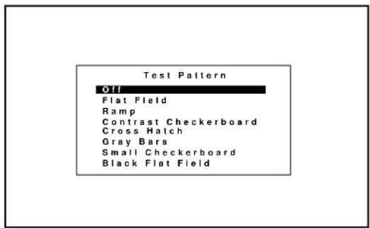
TEST PATTERN
CROSS HATCH FLAT FIELD
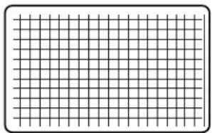
natural_image
Blank grid paper with uniform square cells, no text or symbols present
natural_image
Empty rectangular frame with rounded corners (no text or symbols)GRAY BARS

natural_image
Black and white striped pattern with no text or symbolsCONTRAST CHECKER BOARD

natural_image
Checkerboard pattern with alternating black and white squares (no text or symbols)SMALL CHECKER BOARD RAMP

natural_image
Black and white checkerboard pattern with no text or symbols
natural_image
Two vertical grayscale gradient bars with no text or symbolsBLACK FLAT FIELD

natural_image
Solid black rectangle with rounded corners (no text or symbols)■ Normal, Load, and Cancel Function
Adjustment settings can be returned to the factory preset level, previously stored level, or can be canceled.
To return to the standard level (Normal):
- Press the NORMAL button.
The confirmation message is displayed.
- Use the CURSOR or button to select Yes.
A confirmation message is displayed.
- Press ENTER.
The Normal function is performed.
If you select “No”, you will exit this mode suspending current status.
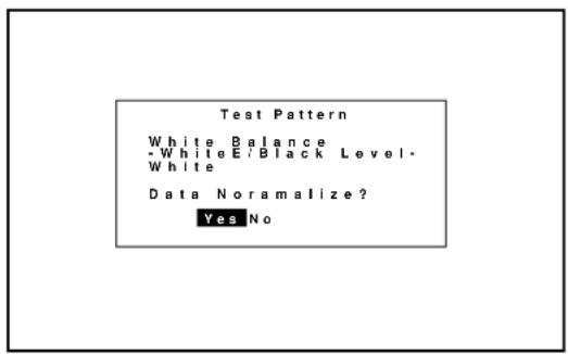
■ To return to the last stored level (Load):
- Press and hold the CTL button then press the NORMAL button.
• The Memory menu is displayed.
- Use the CURSOR or button to select Load.
A confirmation message is displayed.
- Use the CURSOR of button to select Yes.
- If you select No, you will exit this mode suspending current status.
- Press ENTER.
• The LOAD function is performed.
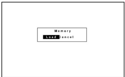
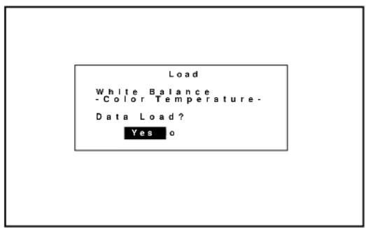
■ To cancel the adjustment data (Cancel):
- Press and hold the CTL button then press the NORMAL button.
• The Memory menu is displayed.
- Use the CURSOR ☑ button to select Cancel.
• A confirmation message is displayed.
- Use the CURSOR or button to select Yes.
- If you select No, you will exit this mode suspending current status.
- Press ENTER.
• The CANCEL function is performed.

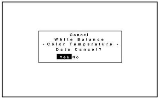

4.SPECIFICATIONS
Projection Type : 3Chip DMD 3Chip DMD ^TM High light output projector.
Projection System : 3chip DMD ^TM , 1 Lens
Display Orientation : Front Floor, Rear Floor,
Front Ceiling, Rear Ceiling
Lamp Type : Bulb type 1.6 KW Xenon Lamp
Shooting offset : Common lens for both XL-3500 and XL-6500
Fixed lens 0±150 pixels
Zoom lens 0
Lens for XL-6500 only
HVL-X1Z/HVL-X2Z 0±360 pixels
HVL-X3Z 0±200 pixels
Scanning line rat : H 15-80KHz
/ Flame rate V 30-120Hz
Resolution : DMD ^TM 1024×768 pixel
Max : 1280 × 1024 by Scaling
Pixel clock : Max 80 MHz
Lens (optional) : Fixed lens (common lens for both XL-3500 and XL-6500)
XL-L1.27: 1.27:1 (for XL-3500) / 1.0:1 (for XL-6500)
XL-L3 : 3.0:1 (for XL-3500) / 2.3:1 (for XL-6500)
XL-L5 : 5.0:1 (for XL-3500) / 3.9:1 (for XL-6500)
XL-L7 : 7.0:1 (for XL-3500) / 5.5:1 (for XL-6500)
Zoom Lens (common lens for both XL-3500 and XL-6500)
XL-L1.5Z : 1.5-3.0 (for XL-3500) / 1.2-2.3 (for XL-6500)
XL-L3Z : 3.0-7.0 (for XL-3500) / 2.3-5.5 (for XL-6500)
Zoom Lens (for XL-6500 only)
HVL-X1Z : 1.5-2.5
HVL-X2Z : 2.5-4.0
HVL-X3Z : 4.0-7.0
Picture Size : 80-500 inch diagonal
Light Output : 6500 ANSI lumen
Contrast Ratio : 350:1 (Full On / Off)
Input terminal :
Fixed terminal :
Composite Video (BNC or RCA switchable)
RGB, H, V / Y, Cr, Cb (BNC)
S Video (S-terminal)
Optional terminal :
2 slot prepared
Input signal (Level) : RGB signal : 0.7Vp-p 75ohm Positive(BNC)
HV sync : 0.7-4.0Vp-p(75ohm/1Kohm)
Negative or Positive(BNC)
Duty 3-30% (H-Sync Positive)
70-97% (H-Sync Negative)
0.1-10%(V-sync Positive)
Negative or Positive(BNC)
G sync : 0.3-0.6Vp-p 75ohm
Sync. Negative(BNC)
Video : 1.0Vp-p 75ohm Sync. Negative
S-Video : Y 1.0Vp-p 75ohm Sync. Negative
C0.28Vp-p 75ohm(burst level)
(3 mode acceptable)
Y, Cr, Cb : Y 1.0Vp-p 75ohm Sync. Negative
Cr,Cb 0.7Vp-p 75ohm (Y,Pb,Pr)
Video System : NTSC, PAL, SECAM, 4.43NTSC
Convergence limits : Within one pixel
Set-up signal : Gray bars signal, Cross hatch signal, Flat field,
Black flat field, Contrast checker board, Small checker board, and Ramp
Power supply : AC 200V - 240V
Power consumption : 2.4KW ( MAX)
Input current : 13.0 A(MAX)
Safety and regulation
UL : Meet UL 1950
CSA : Meet CSA 950
FCC : Meet FCC class A
DHHS : Approved
DOC : Meet
Meet EMC Directive
EN55022 : Meet(Radiation)
EN55082-2 : Meet(Immunity)
EN61000-3-2, EN61000-3-3 : Meet(Disturbance)
Meet LVP Directive
EN60950 :Meet (Safety)
Cabinet dimension : 29.5" (W) x 39.4" (D) x 15" (H) without lens
750 mm (W) x 1000 mm (D) x 380 mm (H) without lens
Weight : 238 lbs (108 kg)
Remote controller : Wired application
(operating distance 23 ft./7m)
External control : Input select ;
Power On/OFF
Mute
PC control : Supports
RS-232C / RS-422 switchable
ISS-6020 Compatibility : Full compatible
OSD Output terminal : D-sub shrink 15 Pin
RGB signal : 0.7Vp-p Analog out (75ohm)
H,V sync out : TTL
Accessory (Option) : Input terminal Option
Environment : Temperature 10 to 40 degrees C
: Humidity 20 to 90% non-condensing
: Storage -10 to 50 degrees C
Lamp life : 1500 Hours (Half light output point)
Noise : 59 dB
Note: Specifications are subject to change without notice.
Message List
| Code | Message | |
| A1 PS PROTECTOR ERROR (load or failure in the mains power supply) | ||
| A2 POWERGOOD ERROR (Insufficient voltage of +5V(D) or DLP5V in the mains power supply) | ||
| C0~CF | COMUNICATION ERROR | (Communication setting errors in conjunction with switcher and PC control) |
| D0 SIGNAL UNLOOK (Instability or failure in synchronization) | ||
| E0 FAN STOP ERROR (Fan stoppage) | ||
| EC FLASH MEMORY ERASE ERROR (Error in system PWB) | ||
| ED FLASH MEMORY WRITE ERROR (Error in system PWB) | ||
| EE ALL STORE DATA INITIAIZING (Store ROM formatting) | ||
| EF PARTLY STORE DATA IS BREAKING (Error in stored data) | ||
| F0 H-FREQUENCY LIMIT OVER (Entry of signal input at 120kHz or above) | ||
| F1 | ENGINE TEMPERATURE ERROR | (Engine temperature deviating the specified range) |
| F2 12CBUS ERROR | (VIDEO PRO PWB or CORE PACK) | (Control error in video PRO PWB/core PACK) |
| F3 12CBUS ERROR (DLP ENGINE) | (Engine control error) | |
| F4 | LAMP PROTECT ERROR | (Lamp source error/lamp error or lamp's fan stop) |
| F5 LAMP STATE ERROR | (Lamp error) | |
| F6 LAMP TEMPERATURE ERROR | (Lamp's temperature error) | |
| F7 MUSEBUS ERROR | (Error in graphic PWB) | |
| P0 FPGA (OSD) WRITING | (Writing in FPGA) | |
| P1 FPGA (R) WRITING | (Writing in FPGA) | |
| P2 FPGA (G) WRITING | (Writing in FPGA) | |
| P3 FPGA (B) WRITING | (Writing in FPGA) | |
| PP BIOS PROGRAM STATING | (Program writing being processed) | |
| o0~oF | Internal processing | |
| LP | LAMP 2000 HOURS OVER | |
NEC
NEC Corporation
Printed in Japan
78409611
- GSGV Acoustic Noise Information Ordinance:
- WARNING
- CAUTION
- DOC compliance Notice
- Precautions
- AVERTISSEMENT
- ATTENTION
- Important Safeguards
- Installation
- Power Supply
- Cleaning
- Fire and Shock Precautions
- Lamp Caution: Please read before operation
- Recommendations importantes
- HOW LONG IS THE WARRANTY
- WHO IS PROTECTED
- WHAT IS COVERED AND WHAT IS NOT COVERED
- WHAT NEC WILL COVER
- HOW YOU CAN GET WARRANTY SERVICE
- LIMITATION OF IMPLIED WARRANTIES
- EXCLUSION OF DAMAGES
- HOW STATE LAW RELATES TO THE WARRANTY
- TABLE OF CONTENTS
- INTRODUCTION
- PART NAMES AND FUNCTIONS
- 2.INSTALLATION
- OPERATION
- SPECIFICATIONS 78......
- APPENDIX
- Congratulations On Your Purchase Of The MultiSync Hivid 6500 Projector
- Features you'll enjoy :
- How Do You Get Started?
- What's In The Box?
- POWER ON/STANDBY Indicator
- BBreakeSwitch
- Remote Sensor
- Power Switch (Main power)
- AC INPUT
- POWER Button
- POWERIndiator
- SSTAANBBYIndiator
- |9| LAMP Indicator
- Two Digit Display
- REMOTE 2 Jacks
- NOTE:
- OPTIONAL Boards
- Corresponding slot number
- 1) When the slot A(Mother board) is selected:
- 3) When the slot C (optional board) is selected:
- 2) When the slot B (optional board) is selected:
- Remote Jack
- POWER Buttons (ON/OFF)
- TEST Button
- ADJUST Button
- OPERATE Button
- Backlight Switch
- PIC CTL Button
- SOUND CTL Button
- PICTURE (PIC) MUTE Button
- SOUND MUTE Button
- DISPLAY Button
- HELP Button
- SIG LEVEL Button
- GAMMA Button
- ADDRESS Button
- PIXEL CLK Button
- PIXEL PHASE
- INPUT Button
- CAPTION Button
- INFO Button
- INPUT LIST Button
- ZOOM/PAN Button
- KELVIN Button
- POSITION Button
- R, G, and B Buttons
- CURSOR Buttons
- DELETE Button
- NORMAL Button
- STORE Button
- END Button
- ENTER Button
- CTL Button
- Remote Control Battery Installation
- Remote Control Precautions
- When using the remote control as the key panel on the projector:
- INSTALLATION
- Setting Up Your MultiSync Hivid 6500 Projector
- Moving The Projector
- Pulling Out the Handles
- Retracting the Handles
- Selecting A Location
- Screen Size and Projection Distance
- Ceiling Installation
- Reflecting The Image
- Rear Screen Projection
- EXAMPLES OF CONNECTIONS.
- CAUTIONS ON CONNECTIONS:
- When Used in Stand Alone Operation
- When Used with One Switcher (ISS-6020/ISS-6020G)
- When Used with Two or More Switchers (100 Inputs)
- How to make connections:
- REMOTE 1 Terminal
- General Controls
- Turn On The Projector
- Select The Computer Or Video Source
- Adjust The Image and The Sound
- Turn Off The Projector
- IMPORTANT:
- Using The On-Screen Menus
- Adjustment Mode
- When a passcode has not been registered:
- When your passcode has already been registered:
- Menu Descriptions & Functions
- About Task bar
- On-Screen Menu Elements:
- Storing Projector Settings (Automatic Save Feature)
- Items to select
- Basic Operation (Operate Menu)
- Source Select
- To select a source using the INPUT buttons on the remote control when no menus are displayed:
- When using the projector with the ISS-6020/ISS-6020G:
- When using the projector with two ISS-6020/ISS-6020G or more:
- Source Information
- ■ Source Name
- ■ Direct Key
- ■ Input Slot
- When used in the stand alone operation:
- When used with a single Switcher ISS-6020/ISS-6020G:
- When used with two or more Switchers ISS-6020/ISS-6020G:
- ■ Display Mode
- ■ Sync System
- On-screen display
- ■ Sync Termination
- ■ Scale Mode
- ■ Input Sig. Size
- ■ Output Sig. Size
- ■ Color Matrix
- ■ CTI(Color Transient Improvement) Control
- ■ Noise Reduction
- ■ Source Select Counter
- ■ Source Display Timer
- Picture Control
- -Picture Control-
- Lens Control
- Display Control
- ■ Pixel Clock / Pixel Phase
- ■ Zoom/Pan
- Image Control
- ■ Image Position
- ■ Blanking
- Sound Control (only when used with the ISS-6020/ISS-6020G Switcher)
- Closed Caption
- Timer Setting
- Adjusting and Setting (Adjustment)
- Source Registry
- On Source Registry
- ■ Source Registry
- To make the signal entry, proceed as follows:
- Source Registry
- New Registry
- 1) To Select a Slot
- When using with a single Switcher ISS-6020/ISS-6020G:
- When using with two or more ISS-6020/ISS-6020G switchers:
- 2) To Select Signal System
- 3) To Set HDTV or not When Selecting Component Signal.
- 4) To Input a User Name.
- 5) To Select a Registry Number.
- ■ Registry Edit
- To edit the registered signal, proceed as follows:
- Amplitude
- White Balance
- Signal Level
- Uniformity
- To Adjust White Uniformity
- -Uniformity-
- Display Function
- 1) Input Signal Size
- 2) Output Signal Size
- 3) Output Position
- 4) Interlace Mode
- 5) Sync Protect
- 6) PLL Gain
- 7) Video Filter
- Lamp Mode
- Set Option
- Passcode
- ■ Entering Passcode
- ■ Registering Passcode
- ■ Changing Your Passcode
- ■ Canceling Your Passcode
- Setting Mode
- ■ PJ Orientation
- -Setting Mode-
- PJ Orientation
- ■ Default Source Select
- When used in stand alone operation:
- When used with a single Switcher:
- When used with two or more Switchers:
- ■ S-Video Mode Select
- NOTE :
- S-Video Mode Select
- ■ Video System Select
- When selecting "AUTO"
- Video Modes
- Video System Select
- ■ Auto Data Store
- Auto Data Store
- ■ Option Terminal Speed
- Option Terminal Speed
- Uniformity Switching
- ■ Uniformity Switching
- Menu Mode
- ■ Message Time
- ■ Date, Time Preset
- ■ Display Item Set
- Execute Mode
- ■ Connect Condition
- ■ PJ Address
- ■ Addressing the Remote Control Unit
- Address common to all the projectors
- ADDRESS
- Help Menu
- ■ Help
- ■ Topics
- ■ Set Information
- Help
- Others
- ■ Test Patterns
- ■ Normal, Load, and Cancel Function
- ■ To return to the last stored level (Load):
- ■ To cancel the adjustment data (Cancel):
- 4.SPECIFICATIONS
- NEC
- NEC Corporation
Brand : NEC
Model : XL-6500
Category : Video projector