
KUMO 6464 - Router AJA - Free user manual and instructions
Find the device manual for free KUMO 6464 AJA in PDF.

| Product Type | SDI Router |
| Brand | AJA |
| Model | KUMO 6464 |
| Video Inputs | 64 x BNC, SMPTE-259/292/424 (3G-SDI) |
| Video Outputs | 64 x BNC, SMPTE-259/292/424 (3G-SDI) |
| Supported Formats | 270 Mbps, 1.5 Gbps, 3 Gbps SDI; DVB-ASI |
| Reclocking | Auto-select for 270 Mbps, 1.483/1.485 Gbps, 2.966/2.970 Gbps |
| Cable Equalization (Belden 1694A) | 3 Gbps up to 140m, 1.5 Gbps up to 200m, 270 Mbps up to 390m |
| Reference Input | 2 x BNC, looping, non-terminating; Blackburst or Tri-level sync |
| Switching Modes | Normal, Dual, Quad link modes |
| Salvos | Up to 8 configurable salvos |
| Control Interface | Web browser (embedded), RS-422, KUMO CP/CP2 panels, GVG Native Protocol |
| Network Interface | 1 x RJ-45, 10/100/1000 Ethernet |
| USB Interface | 1 x Mini-USB for IP configuration (eMini-Setup) |
| RS-422 Serial | 1 x DB-9 Female, GVG Native Protocol (38400 baud) |
| Chassis Size (W x D x H) | 17.4" x 1.54" x 7.00" (441.96 x 39.12 x 177.8 mm), 4RU |
| Weight | 9.2 lbs (4.2 kg) |
| Power Supply | External, dual redundant inputs; AC adapter 100-240VAC, 60W; 32W typical, 36W max |
| Operating Temperature | 0°C to 40°C (32°F to 104°F) |
| Storage Temperature | -40°C to 60°C (-40°F to 140°F) |
| Compliance | FCC Class A, CE, ICES-003, KC, BSMI, VCCI |
| Warranty | 5 years limited hardware warranty |
Frequently Asked Questions - KUMO 6464 AJA
User questions about KUMO 6464 AJA
0 question about this device. Answer the ones you know or ask your own.
Ask a new question about this device
Download the instructions for your Router in PDF format for free! Find your manual KUMO 6464 - AJA and take your electronic device back in hand. On this page are published all the documents necessary for the use of your device. KUMO 6464 by AJA.
USER MANUAL KUMO 6464 AJA
SDI Routers and Control Panels

Installation and Operation Guide
Trademarks
AJA® and Because it matters. are registered trademarks of AJA Video Systems, Inc. for use with most AJA products. AJATM is a trademark of AJA Video Systems, Inc. for use with recorder, router, software and camera products. Because it matters. is a trademark of AJA Video Systems, Inc. for use with camera products.
Corvid Ultra ® , Io ® , Ki Pro ® , KONA ® , KUMO ® , ROI ® and T-Tap ® are registered trademarks of AJA Video Systems, Inc.
AJA Control Room™, KiStor™, Science of the Beautiful™, TruScale™, V2Analog™ and V2Digital™ are trademarks of AJA Video Systems, Inc.
All other trademarks are the property of their respective owners.
Copyright
Copyright © 2022 AJA Video Systems, Inc. All rights reserved. All information in this manual is subject to change without notice. No part of the document may be reproduced or transmitted in any form, or by any means, electronic or mechanical, including photocopying or recording, without the express written permission of AJA Video Systems, Inc.
Contacting AJA Support
When calling for support, have all information at hand prior to calling. To contact AJA for sales or support, use any of the following methods:
| Telephone +1.530.271.3190 |
| FAX +1.530.271.3140 |
| Web https://www.aja.com____ |
| Support Email support@aja.com____ |
| Sales Email sales@aja.com____ |
Contents
Notices 2
Trademarks 2
Copyright 2
Contacting AJA Support 2
Chapter 1 – Introduction .....6
Overview....6
KUMO Features....7
KUMO Router Connections 8
PS1 & PS2 Power Connectors 8
RJ-45 Ethernet Connector 8
Identify LED 8
Reset Button....9
REF BNC Connector 9
Video Inputs and Outputs 9
RS-422 Connector 9
KUMO Control Panel Connections 10
KUMO Control and Monitoring 10
Default Network Settings. 10
In This Manual 10
Chapter 2 – Installation ..... 11
Overview.... 11
What's In The Box? 11
KUMO Chassis Installation 11
Space Requirements.... 11
Cooling Requirements. 12
Power Requirements. 12
Physical Equipment Setup....12
Quick Start Configuration 12
Default Auto Configure KUMO Router and Control Panel ..... 12
DHCP on an Existing Network.... 13
Computer Auto Discovery 13
Network Configuration via USB....14
KUMO Temporary Static IP Address 14
Network Configuration In Depth. 15
LAN Connection Using a Hub or Switch. 16
Setup and Control Methods 16
Setup and Control from a Browser on macOS 17
Safari Browser: Type in KUMO Static IP Address 17
Setup and Control from a Browser on Windows 18
Windows: Using UPnP (Universal Plug and Play) 18
Windows Browser: Type in KUMO Static IP Address 18
Larger System Control Configurations 19
TCP/IP Network Connection 19
Select KUMO to Control from Web Page 20
Assign KUMO CP and CP2 to Control KUMO Routers ..... 20
Locating a Specific KUMO Device on the Network 21
Chapter 3 – Router Web Browser User Interface. . . . . . . . . . . . . . . . . . . . . . . . . . . . . . . . . . . . . . . . . . . . . . . . . . . . . . . . . . . . . . . . . .
Overview....22
Navigation Bar. 22
KUMO Home Screen Device Selection 22
Web Browser Control Surface Operation. 22
Performing a Take 23
Taking a Salvo 23
Router Configuration 23
Mode Selection 24
Button Settings 25
Salvos Configuration 26
Salvos Screen Controls 27
Salvo Configuration Procedure 28
Network Setup 28
Web Browser Refresh 29
User Authentication 29
UPnP Host 30
Firmware Updating 30
Unpack the Software 30
Uploading and Installing Firmware to KUMO 31
Safeboot Reset 32
KUMO Alarms 32
Locating a Specific KUMO 33
Chapter 4 – KUMO Remote Control Panels ..... 34
Overview....34
KUMO Control Panel Installation and Network Configuration ..... 34
Connectors and Indicators 34
Using a Control Panel 35
Performing a Take 35
Taking a Salvo 35
Panel Function Button Descriptions 35
Control Panel Web Browser User Interface 37
HOME Screen 37
CONFIGURATION Screen 38
BUTTONS Screen 38
NETWORK Screen....39
FIRMWARE Screen 39
ALARMS Screen 39
IDENTIFY Tab. 40
Chapter 5 – eMini-Setup ..... 41
Overview....41
Acquiring eMini-Setup 41
AJA Documentation 41
Installing eMini-Setup 42
PC Installation 42
Mac Installation 43
Running eMini-Setup 43
PC Startup 43
Mac Startup 44
Operating eMini-Setup....44
Control Network Tab Screen 45
Info Tab Screen....46
Appendix A – Specifications ..... 47
KUMO 6464-12G Tech Specs 47
KUMO 6464 Tech Specs 48
KUMO 3232-12G Tech Specs. 50
KUMO 3232 Tech Specs. 52
KUMO 1616-12G Tech Specs. 54
KUMO 1616 Tech Specs....56
KUMO 1604 Tech Specs. 58
KUMO CP2 Tech Specs 59
KUMO CP Tech Specs 60
GVG Native Protocol Support....61
NP Commands Supported 61
RS-422 Control Specifications (Routers) 62
Appendix B – Safety & Compliance. . . . . . . . . . . . . . . . . . . . . . . . . . . . . . . . . . . . . . . 63
FCC Caution 63
Warranty and Liability Information....71
Index. 72
Chapter 1 – Introduction
Overview
KUMO compact SDI routers are small and cost-effective, yet robust and reliable. All KUMO routers support full-broadcast specifications over SD-SDI, HD-SDI, and 3G-SDI. A KUMO-12G router also supports single connector 12G-SDI. Additionally, KUMO routers support SDI related protocols such as 270Mb/s DVB-ASI and Canon 3G-SDI RAW. KUMO routers are re-clocking, non-blocking, and ready for any broadcast, production, or post production environment. Running Embedded Linux, KUMO routers support powerful HTTP control and monitoring. Each KUMO product contains an internal web server that allows immediate installation, configuration, and operation without requiring additional software. It offers a powerful user interface via any standard web browser. KUMO SDI routers are available in seven configurations:
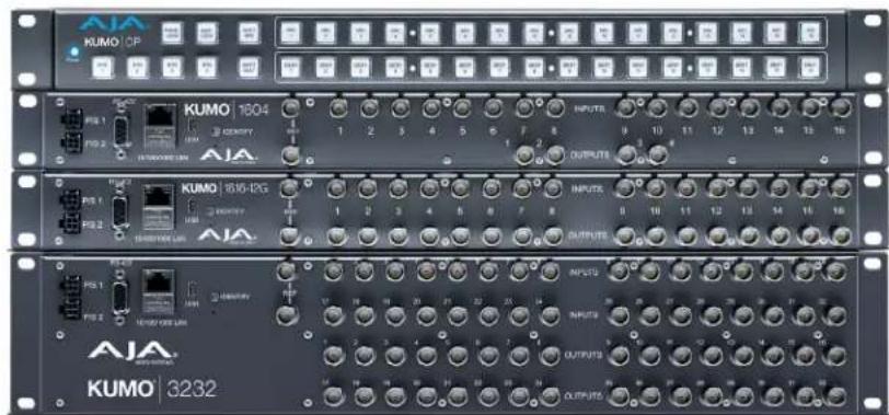
• KUMO 1604 - sixteen SDI inputs and four outputs
• KUMO 1616 - sixteen SDI inputs and sixteen outputs
- KUMO 1616-12G - supports single connector 12G-SDI, sixteen SDI inputs and sixteen outputs
• KUMO 3232 - supports thirty-two SDI inputs and thirty-two outputs
- KUMO 3232-12G - supports single connector 12G-SDI, thirty-two SDI inputs and thirty-two outputs
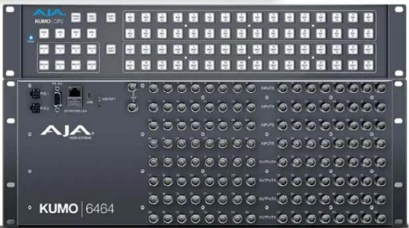
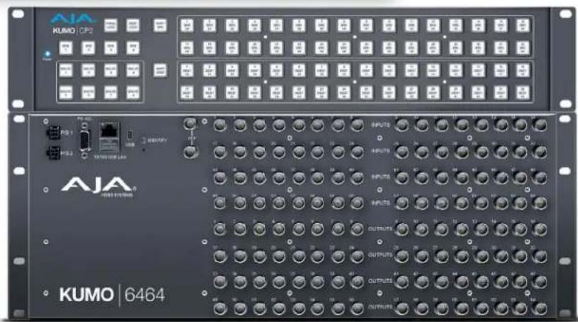
• KUMO 6464 - sixty-four SDI inputs and sixty-four outputs
- KUMO 6464-12G - supports single connector 12G-SDI, sixty-four SDI inputs and sixty-four outputs
Because of their compact sizes, KUMO SDI routers are ideal for space-sensitive applications such as mobile sports trucks, edit suites, corporate video installations, or live theatrical A/V rigs.
KUMO Features
The KUMO routers offer the following features for ease of use in a broad range of SDI applications and workflows:
• KUMO 1604, 1616, and 3232 support for SD-SDI, HD-SDI, 3G-SD (SMPTE 259M/292M/424M)
• KUMO 1616-12G, 3232-12G, and 6464-12G support for SD-SDI, HD-SDI, 3G-SDI, 6G-SDI and 12G-SDI (SMPTE-259/292/424/2081/2082)
- KUMO v3.0 and above firmware supports dual and quad mode routing, allowing users to group together Sources and Destinations for multiple cable applications like Dual Link, Quad HD, Quad split monitors, and even 8K video.
- KUMO v4.3 and above firmware supports salvos, controlled from the KUMO router Web UI and the KUMO CP2 panel.
• Automatic coax cable equalization and re-clocking
- Supports all embedded VANC and HANC ancillary information, including embedded audio
- Reference input via BNC, passive loop, PAL/NTSC color black or Tri-level sync
- Output switch timing per SMPTE RP 168 when using an external reference
• 10/100/1000 Ethernet LAN
- Embedded Linux OS with internal web server for web browser control
- USB port for use with eMini-Setup for network configuration via USB.
- User authorization to restrict access via web browser
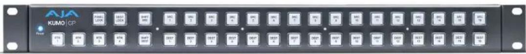
- Optional KUMO CP hardware 32 pushbutton remote control panel via Ethernet
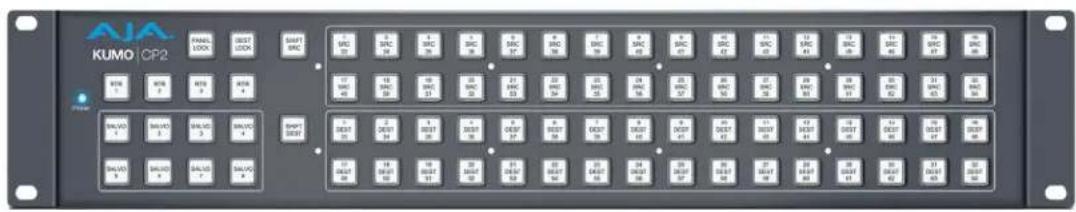
- Optional KUMO CP2 hardware 64 pushbutton remote control panel via Ethernet
- 1RU form factor for KUMO 1604, 1616, and KUMO CP, 2RU for 3232 and KUMO CP2, 4RU for KUMO 6464
- Power loss recovery to the last operational state, both router and control panel
- Redundant power supply (optional), isolated power inputs
NOTE: KUMO routers switch SDI signals in a manner compliant with SMPTE RP 168-2009. Because KUMO routers (or any similar router) switch the SDI stream without de-serializing, the switch point can cause a temporary anomaly in the SDI stream. This can cause downstream equipment, depending on the characteristics of the SDI receiver(s), to react to the switch (for example, a monitor "glitch or roll"). It is also possible that switching anomalies can appear on just one or more outputs in the same group in the Dual and Quad modes and in salvos. This effect occurs regardless of the relative timing of the SDI signals being switched, or any reference input connected to the router.
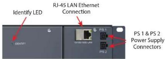
KUMO Router Connections
Figure 1. KUMO Rear Panel Connections (3232 shown, other models similar)
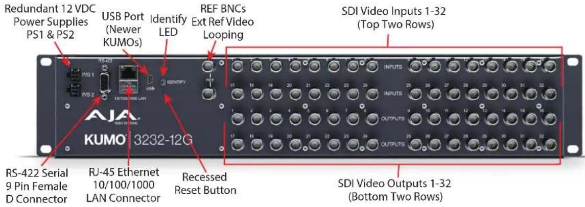
PS1 & PS2 Power Connectors
Power to the KUMO unit is supplied by an external power supply module that accepts a 110-240VAC, 50/60Hz power input and supplies +12 VDC to KUMO via connector PS1 or PS2. One power supply is provided, and it may be connected to either of the two power connectors. An optional second power supply can provide redundancy to help protect against outages.
NOTE: The KUMO 6464-12G router requires an 84W power supply (KUMO-84W-PWR). All other KUMO routers and control panels can use a 60W power supply (KUMO-PWR).
IMPORTANT: The power connector has a latch, similar to an Ethernet connector. Depress the latch (facing the outside edge of the KUMO device) before disconnecting the power cable from the unit.
Power Loss Recovery
If KUMO experiences a loss of power, when power is restored the router returns to the previous state of all Source to Destination crosspoints, and all configured Source and Destination names are retained. If a KUMO control panel configured with a KUMO router loses power, when power is restored the control panel's configuration is retained, and button tallies will return to their previous states.
RJ-45 Ethernet Connector
The RJ-45 Ethernet connector allows you to connect KUMO to a 10/100/1000 Ethernet LAN using CAT5 cable and access KUMO's built in web server. Multiple configurations are possible, including standalone control, a local LAN, or a WAN. This also allows control over the network using GVG Native Protocol.
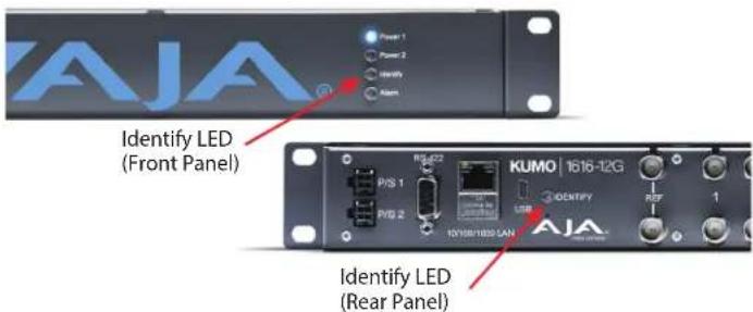
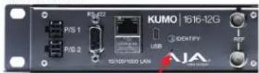
Identify LED
The Identify LED lights when you use the web interface to identify the KUMO unit you are controlling.
Reset Button
The Reset button (pinhole) below the LED allows a safeboot reset of the unit as explained in "Safeboot Reset" on page 32.
REF BNC Connector
The REF BNC connector is the input for synchronizing the crosspoint switch timing of KUMO to your house video signals. Apply an analog NTSC, PAL, or Tri-level sync signal to this input. Be sure to terminate the second BNC with a 75 Ohm terminator, or if you loop to other equipment terminate the last connected device.
When reference is present, KUMO will switch at the SMPTE RP 168 designated switch point with respect to the reference input. If no reference is present, the KUMO will switch based on its internal clock.
Video Inputs and Outputs
Depending on your KUMO model, up to 64 SDI video inputs and outputs can be connected to the video input and output BNC connectors.
Normal Mode
In Normal mode, each input and output BNC routes an individual signal.
Dual and Quad Modes
In Dual mode, inputs and outputs use adjacent pairs of BNCs for each routed signal. In Quad mode, four adjacent BNCs are used for each routed signal. See "Mode Selection" on page 24.
RS-422 Connector
KUMO routers include a RS-422 female DB-9 connector for making serial connections to other equipment. This control connection enables interoperability with other devices, including those that use GVG Native Protocol. See "RS-422 Control Specifications (Routers)" on page 62 for more information.
Older Model RS-422 Adapter
Older KUMO 1604, 1616, and 3232 routers (serial numbers ending in -R0) needed an RS-422 adapter for proper serial control operation (Figure 2). This adapter was shipped with those older model routers. Be aware of this fact if your facility has a mixture of older and newer KUMO routers that use RS-422 control.
NOTE: KUMO routers with serial numbers ending in -R1 or higher do NOT require the adapter, and KUMO 6464 models do NOT require the adapter.
Figure 2. RS-422 Adapter

Similar to the KUMO router, KUMO CP has an RJ-45 Ethernet connector and power supply connectors, but has no BNC connectors and no RS-422 port.
KUMO Control and Monitoring
The KUMO router user-interface provides powerful remote setup, control, and monitoring with:
- Zero-configuration Bonjour Protocol and support for UPnP networking protocols
- Remote web browser control interface via Ethernet
- Optional KUMO CP (32 button) and KUMO CP2 (64 button) hardware control panels, each unit able to control up to four KUMO routers
NOTE: The 32 button KUMO CP hardware Control Panel can be used with a KUMO 6464 router operating in Normal mode, but can only control the first 32 Sources and Destinations. The KUMO CP can be used to fully control a KUMO 6464 that is operating in Dual or Quad mode. Control of the KUMO 6464 router in all modes is available via the KUMO CP2 64 button hardware panel, web browser, Ethernet control, and RS-422.
- GVG Native Protocol built-in to allow serial or LAN interconnection (one RS-422 or up to 32 Ethernet) and interoperability with other equipment. Specifically, KUMO can be controlled by the SMS 7000 portion of the GVG Native Protocol. For details, refer to: "GVG Native Protocol Support" on page 61.
Default Network Settings
KUMO routers and control panels ship with DHCP enabled, making system operation possible simply by connecting the KUMO device's Ethernet cabling. In addition, temporary default static IP addresses can be activated for initial KUMO system configuration. See "KUMO Temporary Static IP Address" on page 14.
In This Manual
Chapter 1: Introduction lists features and gives a general description of the product.
Chapter 2: Installation details KUMO installation, connections, and networking configuration options.
Chapter 3: Web Browser User Interface provides complete instructions for controlling and monitoring the KUMO router from a computer.
Chapter 4: KUMO Remote Control Panels details the configuration and operation of the optional KUMO CP and CP2 Control Panels.
Appendix A: Specifications lists technical specifications for the products.
Appendix B: Safety and Compliance information.
Warranty and Index
Overview
KUMO SDI routers are easy to set up and use. All of the steps for KUMO installation and configuration are documented in this chapter, summarized as follows:
- Install the chassis in an appropriate rack. If you are mounting multiple KUMO units, try to place them visually in the same area so if you communicate with them via a network attached computer, you can use the KUMO's Identify feature to flash the corresponding LED of the unit you're communicating with. Ensure you have an Ethernet cable routed to where the KUMO will be placed.
- Assemble the Ethernet network connections to a closed network or LAN using Cat 5 Ethernet cable and any required switches and hubs.
- Connect the KUMO to power, connecting the power cord to mains AC.
- If necessary, configure device network settings for operation in your facility.
- Cable the system SDI video Source and Destination equipment and reference signals.
- If operating with Dual Link or Quad Link signals, select the appropriate KUMO operating mode.

Warning! Do not defeat the safety purpose of the grounding-type plug

Caution! To meet safety regulations for leakage current when using redundant power supplies, connect the KUMO dual power supplies to separate branch circuits
What's In The Box?
When you unpack your AJA KUMO SDI device, you'll find the following components:
• KUMO SDI router or KUMO control panel
- USB adapter cable
• AC adapter and AC power cord
Please save all packaging for shipping KUMO should you wish to do so when moving or sending it in for service.
KUMO Chassis Installation
Space Requirements
When planning equipment locations and mounting methods, take into account the size of the chassis. KUMO devices are designed for EIA 19" equipment rack mounting. See "Appendix A Specifications" for exact dimensions of each router model.
Plan adequate space for cable routing from the back of the router chassis. Ensure that SDI video cable connectors will not be stressed and that cables are not bent or crimped in the process.
Cooling Requirements
When rack mounting or stacking multiple KUMO chassis, ensure there is adequate airspace for cooling around the KUMO units. Note the location of cooling vents on all equipment next to the KUMO and ensure none are obstructed.
Power Requirements
- Input Voltage: 110-240VAC, 50/60Hz
- 60W or 84W AC adapter provided
- Optional redundant power supply

Caution! KUMO is designed to take advantage of its chassis to aid in cooling. It is common and expected for the densely populated chassis to have a warm front panel in normal, active operating conditions.

Warning! Do not open the chassis. There are no user-serviceable parts inside. Opening the chassis will void the warranty unless performed by an AJA service center or licensed facility. Remove the brick power supply AC line cord(s) from mains power when moving the unit
Physical Equipment Setup
- Connect power supplies (1 or 2 for redundancy) to KUMO routers and control panels.
NOTE: The KUMO 6464-12G router requires an 84W power supply (KUMO-84W-PWR). All other KUMO routers and control panels can use a 60W power supply (KUMO-PWR). - Connect Source and Destination SDI equipment (this step can be deferred).
-
Connect network:
-
Direct Connection: connect a KUMO router to a KUMO CP (if used), or to a Mac or PC, via an Ethernet Cable.
• LAN Connection: connect a KUMO router (and a KUMO CP if used) to a hub or switch and connect a PC or Mac to the same LAN via a hub or switch.
NOTE: KUMO devices are compatible with both Cat 5 straight-through and cross-over Ethernet cables—they automatically detect whichever is used.
- Proceed to your desired network configuration method using one of the procedures presented later in the chapter.
Quick Start Configuration
Default Auto Configure KUMO Router and Control Panel
If you purchased a KUMO control panel along with a KUMO router, the easiest way to get your system operating is to simply direct connect them with a single Ethernet cable and power up both units.
KUMO devices are compatible with both Cat 5 straight-through and cross-over Ethernet cables. The KUMO CP will use an Auto Configure function to set itself up to operate with the KUMO router it is directly connected to. The KUMO CP panel buttons will light and, if SDI BNC connections have been made, you will be able to route Sources to Destinations.
Figure 3. KUMO Router Direct Connection to KUMO CP

The KUMO CP Auto Configure assigns Router Select Button 1 to the attached router.
NOTE: A KUMO CP that has had its network settings configured previously will not use automatic configuration to find a directly connected KUMO router. However, you can force the KUMO CP to enter into Auto Configuration Mode by pressing the RTR 1 and SHIFT DEST buttons simultaneously for four seconds.
DHCP on an Existing Network
NOTE: KUMO devices are shipped from the factory with DHCP configured by default.
An easy way to get your new KUMO routers configured on your network is to simply connect them to an existing network with a DHCP server. When the KUMO devices reset during power up, each KUMO will see the DHCP server and automatically be given compatible IP network settings. If auto discovery is configured on a computer on that network, that computer will be able to find and control the KUMO router via a web browser (see below).
Computer Auto Discovery
Computers can support network auto discovery, which makes the network configuration process easy. Two methods of connecting using this technique are described below.
Older macOS Configuration with Safari Browser Using Bonjour
MacOS Safari browser versions 10 and earlier have Bonjour functionality built-in, which can be used to auto-detect and connect to an Ethernet device like a KUMO Router.
NOTE: Apple removed Bonjour support from Safari versions 11 and higher.
To find a KUMO router using Bonjour on a supported version of Safari:
- Ensure the KUMO to be controlled is powered up and connected via Ethernet (directly to a Mac or via LAN).
- Start Safari browser on a Mac.
- Click on the top menu Bookmark->Bonjour->Webpages drop-down and click on a listed AJA KUMO router or control panel.
NOTE: If Bonjour is not visible in the Bookmark drop-down, go to Safari->Preferences->Advanced and check the "Include Bonjour in the Bookmarks menu" checkbox.
- Safari will display the KUMO web user-interface, which you can use to control and configure that KUMO device.
Windows PC Configuration using UPnP
If your Windows PC supports UPnP protocols (most do) and UPnP network discovery service is enabled (refer to your Microsoft Windows documentation), you can control KUMO routers by simply selecting one from a device list:
- Ensure the KUMO to be controlled is powered up and connected via Ethernet (directly to the PC or via LAN).
- Use your Windows Control Panel or File Explorer to go to Computer->Network.
- Look at the list under "Other Devices"—double click a KUMO's name to launch your Windows PC's default browser.
- The browser will display the KUMO web user-interface, which you can use to control and configure that KUMO device.
Network Configuration via USB
KUMO devices equipped with USB ports can be configured for network operation using AJA's eMini-Setup utility program. The general procedure is:
- Acquire eMini-Setup from the AJA website and install the eMini-Setup application onto a computer.
- Connect the KUMO USB port to that computer's USB port with the supplied USB cable.
- Launch the eMini-Setup application.
- Go to the Network tab where the IP address settings are displayed. You can use the existing DHCP assigned IP address, or it can be changed manually.
See "Chapter 5 eMini-Setup" on page 41 for additional information.
KUMO Temporary Static IP Address
KUMO devices also offer a hardware initiated factory default static IP address, allowing a direct and fail-safe way to connect via a computer connected to KUMO either directly or via a LAN connection. The computer you use will need to be set to a static IP address that is compatible with the KUMO temporary IP address. Once connected, the KUMO device's network settings can be reconfigured to work with your facility network. The KUMO default static IP address is temporary and is intended only to allow an initial connection.
NOTE: All KUMO routers and control panels have the same temporary static IP address, so more than one device set to this default cannot reside on the same network simultaneously. Work with only one device at a time.
Table 1. KUMO Device Temporary Static IP Address Values
| Device IP address Subnet Mask | ||
| KUMO Router and KUMO CP 192.168.101.1 255.255.255.0 |
NOTE: The default static address is temporary and will be disabled the next time KUMO restarts. Any changes in the Network configuration will be saved upon restart.
To set KUMO to its temporary static IP address:
- Power up the KUMO device and wait for it to boot normally.
- Set the KUMO device to its static IP address:
- For a KUMO router, insert a straightened paper clip or similar device into the reset slot on the rear and hold for five seconds and then release. The KUMO
will restart with the default IP. When the KUMO router default IP is set the Identify LED will blink.
- For a KUMO CP/CP2, press and hold the SHIFT SRC and SHIFT DEST buttons on the panel for five seconds and then release. When the KUMO CP default IP is set, the Source and Destination buttons will flash alternately.
NOTE: If a KUMO webpage on a computer is open when that KUMO device is reset, the information displayed on the webpage is not updated automatically.
Figure 4. KUMO Router and KUMO CP Default Static IP Setting
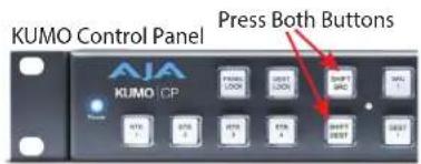

Recessed Button Under Slot
IMPORTANT: Be sure to record your computer's existing TCP/IP settings before the next step so that you can return the computer to normal operation after this procedure.
- Configure your computer to 192.168.101.X. Do not use .1 at the end of the address to avoid duplicate IP addresses.
- Start a web browser and enter 192.168.101.1 as the web address. This is the KUMO temporary static IP address.
- Once you've connected using the static IP, you can then enter a desired network configuration using the KUMO device's NETWORK tab.
Network Configuration In Depth
A LAN is a shared network that includes other Ethernet devices all attached via a hub or digital switch. LANs may be divided into zones separated by software or hardware routers. Routers may also be used to connect the LAN to an outside wide area network (WAN) such as the Internet. Devices on a LAN have IP addresses which may be fixed and permanent, or dynamically assigned by the network (DHCP with DNS server).
NOTE: Once connected and properly configured, the KUMO router can then be controlled by a web browser or one or more KUMO CP control panels. KUMO and KUMO CP are equipped with zeroconf (Bonjour) and support UPnP networking protocols but initially start up as DHCP active devices. If you are operating on a DHCP server, KUMO will take an assigned IP address and appear on the network.

Caution! When attaching KUMO to a standard static IP LAN, you must configure KUMO components with a new, unique IP address. You should first talk to your network administrator and find out how it should be connected (TCP/IP Static IP or DHCP). Your IT department will be able to supply the information you need to install KUMO on a LAN.
KUMO uses TCP/IP network communications and Ethernet connections (a 10/100/1000 Ethernet port) for crosspoint control, status monitoring, and software updates. KUMO devices have an internal HTTP web server that works with a standard web browser on a Mac or PC. An Ethernet cable can also be used to connect an optional KUMO CP (control panel) directly to a KUMO router for operation without a computer.
KUMO devices are compatible with both Cat 5 straight-through and cross-over Ethernet cables—they automatically detect whichever is used.
KUMO's internal HTTP networking software supports three levels of network control:
- Closed KUMO network – uses Default Auto Configure (KUMO CP), or Bonjour (Mac or PC).
- Auto Configured LAN – employs a Bonjour or UPnP enabled computer/browser to automatically connect devices and allows KUMO web browser User Interface (UI).
- Standard TCP/IP network – employs DHCP or Static IP addressing and allows the KUMO web-based UI and an unlimited number of KUMO routers and up to 32 KUMO CP control points.
Once connected, you can use a web browser to:
- Configure any TCP/IP settings
- Select and name KUMO routers and control panels
- Assign a KUMO panel to be able to control specific KUMO routers
• Name Sources and Destinations
• Make Source to Destination assignments (signal routing) - Change router operating mode (Normal, Dual Mode, Quad Mode)
- Set a variety of operational and monitoring options
LAN Connection Using a Hub or Switch
In a LAN connection, connect one or more KUMO routers to your LAN or closed network using Cat 5 Ethernet cable and an Ethernet hub or switch; then power up the equipment.
Figure 5. KUMO Routers on LAN with Web Browser UI
![graph TD A["KUMO 10.16"] --> B["LAN Switches or Hubs"] C["KUMO 10.17"] --> B D["KUMO 10.18"] --> B E["KUMO 10.19"] --> B F["Control Unlimited KUMO Routers via TCP/IP"] --> B G["Web Browser User Interface"] --> B](/content/2026/05/1041731/images/e19a15f34ab2f2b5ecc378b98491be3e9db8bddd9fb3d4f96cf9a42c2e503bf6.jpg)
Setup and Control Methods
Regardless of direct connection or LAN connection, KUMOs are controlled over a network by connecting to KUMO's internal web server with a standard web browser on a Mac or PC. To do this you first need to establish a network connection between the computer and the KUMO to be controlled. There are various methods supported for doing this depending on the operating system and/or web browser being used.
When using KUMO in a DHCP or Static IP addressed network, it is best to select and maintain a consistent network scheme. If you use a mix of DHCP and Static IP addresses, inconsistent performance can result. The most stable operation is achieved when all IP addressing is either DHCP or Static.
Setup and Control from a Browser on macOS
Safari Browser: Type in KUMO Static IP Address
KUMO offers a factory default static IP address. The default static IP address is temporary and is intended only to allow an initial connection. Once you've connected using the static IP, you can then change that KUMO's IP address to one compatible with your network, using KUMO's NETWORK tab.
NOTE: The default static address is temporary and will be disabled the next time KUMO restarts. Any changes in the Network configuration will be saved upon restart.
-
Set the KUMO to its factory default IP address. See "KUMO Temporary Static IP Address" on page 14 for this procedure.
-
Configure your computer to communicate on the 192.168.101.X subnet as shown below:
IMPORTANT: First record existing TCP/IP settings so that you can return your computer to normal operation after this procedure.
A. Go to your System Preferences>Network and select Ethernet and Configure: Manually.
Figure 6. Mac Network Setup Screen (System Preferences -> Network)
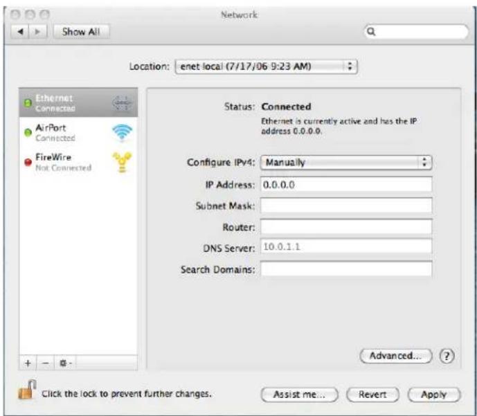
B. Input the address information shown below:
- IP Address: 192.168.101.X (do not use .1 in the last octet).
- Subnet Mask: 255.255.255.0
C. Click Apply.
-
Ensure the KUMO device to be controlled is connected to the Mac via Ethernet (directly or via LAN).
-
Start Safari and enter 192.168.101.1 as the web address. This is the KUMO temporary static IP address.
- Once you've connected to KUMO's web interface, reconfigure KUMO's network parameters as desired using the KUMO device's NETWORK tab.
- Restore your computer to its normal network settings using this procedure and the IP addresses you recorded earlier.
Setup and Control from a Browser on Windows
The easiest methods of setting up a controlling a KUMO device from a PC running Windows are:
- Setup and Control from a Browser on Windows using UPnP
- Setup and Control from a Browser on Windows using a Static IP Address
Windows: Using UPnP (Universal Plug and Play)
This method was covered earlier in this chapter.
See "Windows PC Configuration using UPnP" on page 14.
Windows Browser: Type in KUMO Static IP Address
KUMO offers a factory default static IP address. The default static IP address is temporary and is intended only to allow an initial connection. Once you've connected using the static IP, you can then enter a desired network configuration using KUMO's NETWORK tab.
NOTE: The default static address is temporary and will be disabled the next time KUMO restarts. Any changes in the Network configuration will be saved upon restart.
- Set the KUMO to its factory default IP address, using the rear Reset button (KUMO Router) or SHIFT Buttons (KUMO CP). See "KUMO Temporary Static IP Address" on page 14 for this procedure.
- Configure your computer's IP address and Subnet Mask using the standard Windows IP configuration steps appropriate for your installed Windows version.
IMPORTANT: Record your computer's existing TCP/IP settings. You will later need to restore these original settings so that you can return your computer to normal operation after this procedure.
- IP Address: 192.168.101.X (do not use .1 in the last octet)
-
Subnet Mask: 255.255.255.0
-
Connect the Windows PC to KUMO's RJ-45 port (either direct or through your LAN)
-
Point your web browser to 192.168.101.1 as the web address. This is the KUMO temporary static IP address.
-
Once you've connected to KUMO's web interface, reconfigure KUMO's network parameters as desired using the KUMO device's NETWORK tab.
-
Restore your computer to its normal network settings using this procedure and the IP addresses you recorded earlier.
Larger System Control Configurations
Figure 7. Multiple KUMO Routers and KUMO CPs with Web Browser UI Control.
![graph TD A["Multiple KUMO CPs anywhere on the network, each CP can control up to four compatible KUMO routers at a time."] --> B["LAN Switches or Hubs"] C["KUMO 3230"] --> B D["KUMO 3232"] --> B E["KUMO 1636"] --> B F["KUMO 1636"] --> B G["KUMO 3232"] --> B H["AJA"] --> B I["AJA"] --> B J["AJA"] -->…](/content/2026/05/1041731/images/1b0c1a08010c237c406af2e8045a42dd547b8bbd97c301a2fe27a7342f4c0893.jpg)
NOTE: The 32 button KUMO CP hardware Control Panel can be used with a KUMO 6464 router operating in Normal mode, but can only control the first 32 Sources and Destinations. The KUMO CP can be used to fully control a KUMO 6464 that is operating in Dual or Quad mode. Control of the KUMO 6464 router in all modes is available via the KUMO CP2 64 button hardware panel, web browser, Ethernet control, and RS-422.
If the KUMO will be attached to a WAN, talk to your IT administrator and obtain the details on how to configure the KUMO (DHCP or static IP).
TCP/IP Network Connection
KUMO supports traditional TCP/IP networking through DHCP or Static IP addressing.
IMPORTANT: When using KUMO in a DHCP or Static IP addressed network, it is best to select and maintain a consistent network scheme. If a mixture of DHCP and Static IP addresses are used, inconsistent performance can result. The most stable operation is achieved when all IP addressing is either DHCP or Static.
Default DHCP Configuration
DHCP is the default initial configuration routine for KUMO devices. If you start up on a DHCP network, KUMO will accept assigned IP addresses. After DHCP initialization, use your zeroconf browser to view the KUMO web page and view the assigned IP address.
Static IP Configuration
If your IT administrator prefers an assigned IP address that is fixed (called a "Static IP"), you will need to set network parameters using the KUMO UI NETWORK Screen where you will enter:
• IP address type—Static IP
- a unique IP address
- the Netmask and Default Gateway IP address (your LAN's router that does the network's routing)
You will need to press the Enter key on the keyboard for every field changed. Press the Update Network Settings button when all fields are complete.
Figure 8. KUMO User Interface Network Tab
Select KUMO to Control from Web Page
Each KUMO device has a built in web server that generates a web page. KUMO devices see each other on the network and list those other KUMO devices in their web pages. From the HOME Screen, use the pulldown menu in the upper left to see all of the KUMO devices present on the local LAN and select the router you want to control, or select the KUMO CP you want to use.
Figure 9. KUMO Router Selection

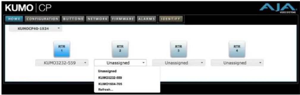
Assign KUMO CP and CP2 to Control KUMO Routers
With multiple KUMO routers and KUMO control panels on the same network, you can assign which routers are able to be controlled by a panel by configuring the four Router Select buttons on the panel. On the KUMO control panel web page, go to the HOME Screen, click on the box below the RTR button, and select the KUMO router from the drop-down list.
Figure 10. KUMO Control Panel Router Button Assignment
Locating a Specific KUMO Device on the Network
IDENTIFY Tab
Click on the IDENTIFY tab to find the physical location of the currently controlled KUMO router or panel.

The web browser IDENTIFY tab will alternate between blue and gray background color in Identify mode. Click again to turn the Identify function off.
- On a KUMO router, the identify LEDs on the front and back will flash, enabling quick physical location of the router in a populated rack of equipment.
- On a KUMO CP, the Source and Destination button rows will flash alternately.
Figure 11. KUMO Router Identify LEDs.
Chapter 3 – Router Web Browser User Interface
Overview
An optimized web server inside the KUMO allows you to remotely monitor and adjust parameter settings via a network-attached computer running a web browser.
NOTE: In this chapter a KUMO 3232 is used as the example. Other models will have different numbers of buttons.
Navigation Bar
The KUMO web browser user interface (UI) provides a navigational bar of tabs for access to control screens and the Identify feature:
- HOME – control surface tab for salvo/Source/Destination selections
- CONFIGURATION – custom naming for Sources and Destinations, Destination lock control, and mode selection
• SALVOS – salvo configuration - NETWORK – IP settings for LAN/WAN operation and enabling authentication
- FIRMWARE – update menu for KUMO firmware from AJA
- ALARMS – log of service failures and allows alarms to be suppressed
- IDENTIFY – toggles activation of Identify LEDs for easy location of KUMO devices.
Figure 12. KUMO Navigation Bar

Click any of the first six tabs to jump to that screen. To the right of the IDENTIFY tab you will see the format of the Reference Video signal being used (if present).
KUMO Home Screen Device Selection
From the HOME Screen (Figure 13 on page 23), you can use the pulldown menu in the upper left to see all of the KUMO devices present on the local LAN and select the one you want to control or monitor.
Web Browser Control Surface Operation
On the HOME Screen immediately below the KUMO selection menu are the Salvo buttons, below them the Source (input) buttons, and below them the Destination (output) buttons.
Clicking on any Destination button will highlight it, and its currently selected Source button will also be highlighted.
Figure 13. KUMO Web Browser Home Screen (3232 Router)

NOTE: Using the CONFIGURATION tab, you can hide Destination buttons that you do not want to control from this screen (see "Hide" on page 26).
Performing a Take
- Go to the KUMO router HOME Screen and select the router you wish to control with the drop down menu.
- Press the desired Destination button. It will illuminate.
- Press the desired Source button. That Source will be routed to that Destination and the Source button will illuminate.
NOTE: Sources for locked Destinations cannot be changed.
Taking a Salvo
Up to eight salvos can be configured on a KUMO router. Each salvo can route any number of Sources to any number of Destinations, including the same Source to multiple Destinations. Paths not included in a salvo remain unchanged. Configured Salvo buttons are colored green on the HOME Screen. See "Salvos Configuration" on page 26 to learn how to configure salvos.
Performing a salvo is a two stage process. First you arm the salvo, and then you take the salvo.
- Go to the KUMO router HOME Screen and select the router you wish to control with the drop down menu.
- Press the desired configured Salvo button. The TAKE SALVO button on the right will be colored red.
- Press the TAKE SALVO button. All Sources configured in that salvo will be routed to their Destinations.
NOTE: Salvos do not change locked Destinations.
Router Configuration
From the Configuration screen you can select the operating mode (Normal, Dual, Quad), change the Source and Destination names and the colors of the buttons, and Lock and Hide Destination buttons.
Figure 14. KUMO Web Interface, I/O Configuration Screen

Mode Selection
Click on the Signal switching mode drop down list to select Normal, Dual, or Quad operating mode. When Dual or Quad mode is selected, the number of Source and Destination buttons will be reduced to match that configuration.
Figure 15. Dual Mode Reduced Sources and Destinations

Figure 16. Quad Mode Reduced Sources and Destinations

NOTE: Changing the router configuration operating mode (Normal, Dual, or Quad) resets the KUMO 6464-12G Long Cable settings. See "Long Cable (KUMO 6464-12G model only)" on page 26.
In Dual and Quad modes adjacent BNCs are used for each routed signal. See Table 2 on page 25 for details.
Table 2. Dual and Quad Mode BNC Connectors and Signal
| Dual Mode Quad Mode | ||||||
| BNC # | Signal | BNC # | Signal | BNC # | Signal | |
| 1-2 | 1 | 33-34 | 17 | 1-4 | 1 | |
| 3-4 | 2 | 35-36 | 18 | 5-8 | 2 | |
| 5-6 | 3 | 37-38 | 19 | 9-12 | 3 | |
| 7-8 | 4 | 39-40 | 20 | 13-16 | 4 | |
| 9-10 | 5 | 41-42 | 21 | 17-20 | 5 | |
| 11-12 | 6 | 43-44 | 22 | 21-24 | 6 | |
| 13-14 | 7 | 45-46 | 23 | 25-28 | 7 | |
| 15-16 | 8 | 47-48 | 24 | 29-32 | 8 | |
| 17-18 | 9 | 49-50 | 25 | 33-36 | 9 | |
| 19-20 | 10 | 51-52 | 26 | 37-40 | 10 | |
| 21-22 | 11 | 53-54 | 27 | 41-44 | 11 | |
| 23-24 | 12 | 55-56 | 28 | 45-48 | 12 | |
| 25-26 | 13 | 57-58 | 29 | 49-52 | 13 | |
| 27-28 | 14 | 59-60 | 30 | 53-56 | 14 | |
| 29-30 | 15 | 61-22 | 31 | 57-60 | 15 | |
| 31-32 | 16 | 63-64 | 32 | 61-64 | 16 | |
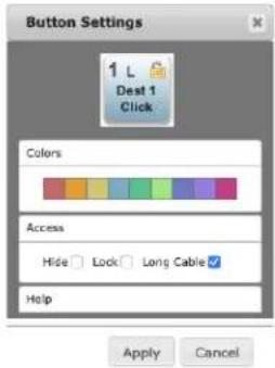
Button Settings
In the Configuration screen you can click on any button to access the Button Settings panel. In the panel, assign a custom name and button color. For Destinations, access settings are also available.
Click on the Apply button to commit your changes, or Cancel to exit the pane without making any changes.
Color Settings
The colored boxes allows you to pick a color from the settings panel to color code the button backgrounds. The selected color is set for both the static state color and the High Tally (rollover/active) state.
Figure 17. Source and Destination Button Color Settings

Access Settings
Access settings permit you to hide or lock individual Destinations. On KUMO 6464-12G routers that individual Destination's cable length can also be specified.
Figure 18. Button Access Settings
Hide
You can hide selected Destinations from display on the HOME Screen by activating the Hide box. This setting applies only to the local browser.
Lock
If you want to lock any of the Destinations from Source changes, activate the Lock box for the desired Destination.
NOTE: This lock is a universal lock for all KUMO devices controlling the selected Destination. It is tallied throughout the network and can be released from other KUMO control devices on the network.
Long Cable (KUMO 6464-12G model only)
The KUMO 6464-12G router includes an additional SDI output setting to increase interoperability with downstream equipment when short output cables are used. The setting is available for each individual output. The default setting is L (for long cable) and can be set to S (for short cable), which may improve performance when the output cable is 10m or less of Belden 1694A or equivalent.
NOTE: Changing the router configuration operating mode (Normal, Dual, or Quad) resets the KUMO 6464-12G Long Cable settings. These settings will need to be manually re-configured to match the actual cable lengths used by each output port in the new operating mode.
Reset to Factory Defaults
The "Reset to Factory Defaults" button can be used to return all router user settings to factory defaults.
Salvos Configuration
The Salvos screen lets you configure up to eight salvos for the selected KUMO router. Each salvo can route any number of Sources to any number of Destinations, including the same Source to multiple Destinations. Crosspoints not included in a salvo remain unchanged.
When you first select the Salvo screen the eight Salvo buttons are shown. Buttons with currently configured salvos are colored green.
Enable Exit Page Warning
The "Enable Exit Page Warning" checkbox enables or disables the display of a warning message if you leave the Salvo configuration screen without saving.
Figure 19. Initial KUMO Salvos Screen

Clicking on one of the eight Salvo buttons selects that salvo for configuration. After selection, a router table appears below with Sources listed vertically and Destinations listed horizontally. After a salvo is configured, you will need to save the crosspoint takes for that salvo.
Figure 20. KUMO Salvos Screen with Router Table

Salvos Screen Controls
Salvo Select Buttons
At the top of the Salvos screen are eight Salvo select buttons. Configured buttons are colored green, and the button for the currently selected salvo is highlighted.
Change Salvo Name
You can enter a name into this field for the selected salvo.
NOTE: Salvo names should be unique.
Load Current Routes
Click to load the current KUMO crosspoint status into the table below. All crosspoints that have been set will be displayed.
Load Selected Salvo
Click to clear any current configuration from the router table and load the crosspoint paths from the currently selected salvo into the table.
Clear Selections
Click to clear all the paths from the router table.
Save Routes To Salvo
After configuration, click on this button to save the selected salvo.
NOTE: If you leave the page without saving, all the changes made to the selected salvo will be lost.
Salvo Configuration Procedure
- Go to the KUMO router HOME Screen and select the router you wish to control with the drop down menu.
- Go to the Salvos screen and select the salvo to be configured.
- If you want to edit the name of the salvo, click on its name in the field on the right, type in a new unique name, and press the Enter key to save the name. Clicking outside the field will undo any typed changes.
- Select the crosspoint(s) in the Salvo Editor below for the routes to include in this salvo. Sources are listed vertically, and Destinations horizontally.
- Clicking on the empty box below the left Source column header creates a one to one (diagonal) salvo in the router table.
- Clicking on any Source number applies that same Source to all the Destinations.
- Click the Save Routes To Salvo button to save the current router table to that salvo.
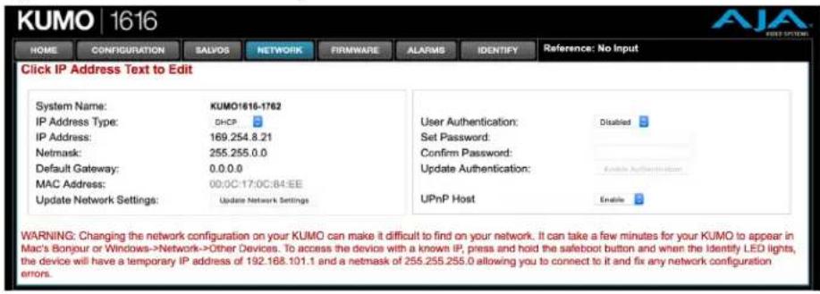
Network Setup
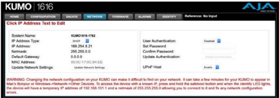
The NETWORK Screen provides access to standard TCP/IP setup fields and allows you to click on the "System Name" field to change it. The MAC address is a fixed machine address composed of manufacturer identification and product serial numbers.
You can choose DHCP or Static IP with the drop down menu. When Static IP is selected the fields below are able to be edited. After changing the network type or entering Static IP information, click the Update Network Settings button to commit your settings.
Figure 21. KUMO Network Setup Screen
IMPORTANT: The KUMO Web UI does not automatically update its network data if something other than that specific browser window is used to change that KUMO's configuration.
Web Browser Refresh
The following actions can result in the display of inaccurate data in the web browser:
• Using the factory reset button.
- Using eMini-Setup to change configuration over USB.
- Changing configuration from another browser, or even the same browser in a different tab.
To workaround this problem, manually refresh the browser window to display the latest network data.
User Authentication
This parameter enables or disables an authentication login requirement. By default this parameter is set to Disabled.
When you select Login as the User Authentication choice, you then must set and confirm a password. To save these settings select the Enable Authentication button. You can change the password using the NETWORK Screen.
When User Authentication is set to Login, you are directed to the login screen before you can access KUMO over the network. You are required to log in with a password before you can access any other KUMO screens.
NOTE: If authentication is used, it provides only a minimum security safeguard against unauthorized use. The authentication mechanism is simple and does not provide robust security.
Password Reset
You can use a password reset procedure to set the KUMO device's password back to the default value, allowing network access to the device if the password should become lost or mistakenly changed. The default password is "password".
After resetting the password, the current KUMO authentication setting itself is not changed. If authorization is enabled, after resetting the password you will need to enter "password" (the default) to gain network access.
KUMO Router Password Reset
-
For a KUMO router, insert a straightened paper clip or similar device into the reset slot on the rear, hold in for more than eight seconds and then release.
-
The Identify LED will blink, then light steadily, and then go out, indicating the password has been reset to default.
KUMO Control Panel Password Reset
- For a KUMO CP/CP2, press and hold the two SHIFT buttons on the panel for more than eight seconds and then release.
- The Panel Lock button will be colored red and then go out, indicating the password has been reset to default.
UPnP Host
UPnP Host enables the KUMO to be discovered by a Windows network.
Selecting Enable (default) allows KUMO to be discovered by a Windows network. Selecting Disable prevents Windows network discovery of the KUMO.
Firmware Updating
AJA is constantly upgrading its product software so it is a good idea to check the AJA website often for updates and to assure optimum system performance. Go to the AJA KUMO Update web page by clicking the link at the bottom of the FIRMWARE Screen, or using the following link:
https://www.aja.com/family/kumo#support
Click on any of the KUMO products to go to its support tab.
Current firmware version number is reported here under the pull-down menu, and the device's serial number is listed at the bottom of the screen.
Figure 22. KUMO Web Interface, Firmware Upload Screen

Unpack the Software
Download the latest version of KUMO firmware and use the FIRMWARE Screen to upload it to your KUMO router. KUMO software update files are "ZIP" files, which you can open with a number of standard and third party uncompressor applications. The software image that you'll install on KUMO is a file with a name similar to:
- kumo_ver_4.0.0.3-1475859474.bin
NOTE: Depending on your PC or Mac operating system settings, the ".bin" extension may not be visible to you in a file directory.
Uploading and Installing Firmware to KUMO
Uploading and installing the software update only requires a PC or Mac that can "see" the KUMO via its browser. Follow this procedure to install the software:
- Launch a browser on your PC or Mac and connect to the KUMO product that requires a firmware update.
- Once the KUMO web page is visible, click on the FIRMWARE tab.
- Then click on the Choose File button to locate the KUMO firmware image file on your PC or Mac.
Figure 23. KUMO Firmware Screen, Choose File for Firmware

- When you have selected a valid KUMO firmware file, click Open and then OK. The file you select will upload to the KUMO and be tested for validity. Incomplete, corrupted, or non-KUMO software files are rejected.
- When the upload completes you will be asked if you want to commit the firmware to flash. Click Commit Uploaded Firmware. The firmware will be loaded to flash. Wait for this to complete.
- When done, click the Restart button to restart your KUMO and refresh the web browser and KUMO UI.
Figure 24. KUMO Firmware Screen, Success and Restart

Once these steps are complete, the KUMO will be running the software you just uploaded. The configuration of the KUMO prior to the upgrade is preserved.
Verify the new software is running by bringing up the KUMO web page again. Check the Firmware page for the current version number. The restart and refresh cycle may take a couple of minutes. If the firmware version does not display the new version, perform the update steps again.
NOTE: On some browsers, the Retry page may appear even though the software upgrade was successful. If this occurs, before clicking on retry, refresh the web page and check the version number. If the new version number appears at the top of the page, the software upgrade was successful. If the old version appears, click Retry.
If there is a power outage or glitch during the software download, the KUMO will boot the older software version and the upgrade process can then be re-started by the user. This happens because the KUMO has been designed with a safety feature where an internal "safe" copy of the previous software is retained in the event the updating process fails.
Safeboot Reset
If your KUMO firmware becomes corrupted to the point of freezing the device, you can reset to a safeboot firmware image. The existing KUMO network configuration (DHCP or Static IP) is retained during safeboot. When safeboot is active you can then re-install the latest firmware via the web interface to regain full system operation.
IMPORTANT: A KUMO device running safeboot firmware is not operational other than being accessible on a network so compatible firmware can be installed.
To perform a KUMO safeboot:
- Power down the KUMO device.
-
Engage the reset function:
-
For a KUMO router, insert a straightened paper clip or similar device into the reset slot on the rear.
-
For a KUMO CP, press and hold both the SHIFT SRC and SHIFT DEST buttons on the panel.
-
Apply power to the device, wait at least 5 seconds and then release the reset function.
Figure 25. KUMO Reset Locations

KUMO Router
Recessed Button Under Slot
KUMO Alarms
KUMO reports alarms on the router front panel by lighting an Alarm LED and in the web browser UI by illuminating the border of the Alarms tab (see below). Alarms include:
- Power Supply – displays error if a redundant power supply is off-line
- Reference – displays error if no valid video reference signal is found
• Over Temperature – displays error if KUMO exceeds normal operating temperature
Figure 26. KUMO Web Interface, Alarms Screen

If you do not want any of the above conditions to report an error, click the boxed text to access the drop-down menu shown above. Select Suppress and click OK to deactivate the specific alarm.
Locating a Specific KUMO
Click on the Web UI IDENTIFY tab to find the physical location of the currently controlled KUMO Router or Panel.

See "Locating a Specific KUMO Device on the Network" on page 21 for more information.
Chapter 4 – KUMO Remote Control Panels
Overview
The KUMO hardware panels are Destination-oriented control panels allowing selection of Sources and Destinations on each of up to four KUMO routers. A KUMO control panel will connect to a single KUMO router automatically without computer/browser interface. For connection to up to four routers on a single CP, use the KUMO browser interface to assign the router select buttons to any four KUMO routers on your network.
Two KUMO hardware panels are available, the KUMO CP able to control up to 32 Sources and Destinations, and the KUMO CP2, able to control up to 64.
NOTE: The 32 button KUMO CP hardware Control Panel can be used with a KUMO 6464 router operating in Normal mode, but can only control the first 32 Sources and Destinations. The KUMO CP can be used to fully control a KUMO 6464 that is operating in Dual or Quad mode. Control of the KUMO 6464 router in all modes is available via the KUMO CP2 64 button hardware panel, web browser, Ethernet control, and RS-422.
KUMO Control Panel Installation and Network Configuration
Refer to "Chapter 2 Installation" on page 11 for detailed information about KUMO hardware control panel installation and network configuration.
Connectors and Indicators
Figure 27. KUMO CP Connectors and Indicator
Power Connectors
KUMO CP provides inputs for two power supplies—one included, redundant supply optional.
IMPORTANT: The power connector has a latch, similar to an Ethernet connector. Depress the latch (facing the outside edge of the KUMO device) before disconnecting the power cable from the unit.
Ethernet Connector
An RJ-45 connector provides 10/100/1000 Ethernet connection to the internal Linux OS/web server.
Identify LED
The Identify LED lights when you use the web interface to identify the KUMO unit you are controlling.
Button Key Caps
Each control panel button has a removable lens cap that allows you to customize Source and Destination names. AJA has provided a template for printing custom lens chips (we suggest using 29 lb. vellum) for button designations. The template is available at:
https://www.aja.com/support/kumo/lens_chip.zip
Using a Control Panel
Performing a Take
- Select the router you wish to control with a Router delegation button.
- Press the desired Destination button. It will illuminate.
- Press the desired Source button. That Source will be routed to that Destination and the Source button will illuminate.
NOTE: Sources for locked Destinations cannot be changed.
Taking a Salvo
Up to eight salvos can be configured on a KUMO router. Each salvo can route any number of Sources to any number of Destinations, including the same Source to multiple Destinations. Crosspoints not included in a salvo remain unchanged. See "Salvos Configuration" on page 26 to learn how to configure salvos.
Performing a salvo is a two stage process. First you arm the salvo, and then you take the salvo.
- Press the desired Salvo button. The button will blink for five seconds.
- Press that blinking Salvo button again to take that salvo.
After five seconds, the Salvo button will no longer be armed and will stop blinking. To take that salvo you will need to press the Salvo button again to rearm that salvo.
NOTE: Salvos do not change locked Destinations.
Panel Function Button Descriptions
Each KUMO Control Panel provides:
- Panel Lock – prevents Source or Destination changes from this panel.
- Destination Lock – prevents any Source change for a Destination.
- Router Delegation Buttons – (RTR 1–RTR 4) enable immediate control of the KUMO assigned to the button.
Figure 28. KUMO CP Function Buttons

Panel Lock
When you press the PANEL LOCK button, it lights red and all panel functions for this panel are disabled. All other KUMO devices on the network will function normally.
Destination Lock
Press the DEST LOCK button to prevent any changes to the KUMO Destination you are currently controlling (DEST button high tallied). The lock can be removed from any other KUMO CP or browser interface on the network.
The locked Destination button and DEST LOCK buttons turn red on all panels that are assigned to the KUMO you are controlling. You can select other Destinations and apply the Destination Lock function to each. All locks will tally red. To remove the lock, select the Destination and press DEST LOCK again.
Locked Destinations are reported on the KUMO router's browser HOME Screen with a lock icon.
Figure 29. KUMO Router Home Screen Destination Buttons

Router Delegation Buttons (RTR 1 - 4)
Use the Router delegate buttons to connect to the specific router to be controlled.
You can assign the delegate buttons to any of up to four routers in your system. To assign router/control panel delegation, access the HOME Screen for your KUMO CP.
If network communications between a control panel and router fails, the control panel's delegation button for that router will be colored pink. When communications is restored the delegation button returns to its normal color.
Shift/Reset Buttons
The SHIFT SRC and SHIFT DEST buttons serve multiple functions. They allow you to select shifted Sources and Destinations (17-32 for KUMO CP and 33-64 for KUMO CP2), and they also perform the same reset functions as the reset slot. Resets should be done only by qualified network personnel:
- Shift: Hold down SHIFT SRC and press a Source button to select a shifted Source, or hold down SHIFT DEST and press a Destination button to select a shifted Destination. When a shift button is not held down, pressing a Source or Destination button selects the unshifted Source or Destination (1-16 for KUMO CP or 1-32 for KUMO CP2).
- IP Reset: See "KUMO Temporary Static IP Address" on page 14.
- Password Reset: see "Password Reset" on page 29.
- Reset to Safeboot Firmware: See "Safeboot Reset" on page 32.
SALVO Buttons (CP2 Only)
The eight Salvo buttons, when configured, can each be used to perform multiple Source to Destination takes using just that one button.
Performing a salvo is a two stage process. First you arm the salvo, and then you take the salvo.
- Press the desired Salvo button. The button will blink for five seconds.
- Press that blinking Salvo button again to take that salvo.
NOTE: Salvos do not change locked Destinations.
Control Panel Web Browser User Interface
The KUMO CP browser interface provides many of the same Navigation Bar tabs as the router. This section discusses those functions unique to the control panel interface.
HOME Screen
Use the HOME Screen to assign a router to each of the router delegation buttons. Each button has a pulldown menu that lists the active networked KUMOs for assignment and provides an Unassign and Refresh function.
Figure 30. KUMO CP Browser Interface Home Screen

The assigned router name appears below each button. You can change the selected (currently-controlled) router on the panel by clicking the button on the HOME Screen. The panel's router delegation button will tally appropriately.
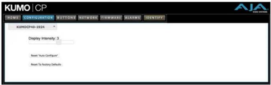
CONFIGURATION Screen
Using the CONFIGURATION screen, you can:
- Adjust the Display Intensity slider – select one of four button illumination levels.
- Reset "Auto Configure" – resets the Auto Configure function to automatically set up one control panel to one router. This function re-boots the panel to trigger the configuration. Upon reboot, if any other router is found on the network, it will not pair to the panel.
- Reset to Factory Defaults – resets all control panel settings to factory defaults, including System Name and Network settings.
Figure 31. KUMO CP Browser Configuration Screen
NOTE: If a KUMO webpage on a computer is open when that KUMO device is reset or had its network configuration changed from another location (even if using a different tab in the same browser), the information displayed on that original webpage will not be updated automatically and so will display stale data.
BUTTONS Screen
The BUTTONS Screen lets you enable or disable the Source, Destination, and Salvo buttons on a KUMO hardware control panel
Disabling Control Panel Buttons
The v4.1 and higher KUMO firmware includes a button disabling feature, useful to uniquely configure the button operation of each KUMO CP/CP2 for specific work areas and specific workflows.
NOTE: This feature is not a router Destination or Source lock. Takes can still be performed on paths with disabled buttons, using the KUMO Web UI or another KUMO control panel.
The current KUMO CP configuration is retained after a power cycle, including any disabled Source or Destination buttons.
NOTE: Performing a KUMO CP factory reset clears the configuration. All Salvo, Source and Destination buttons are enabled after a factory reset.
Procedure
- Access the KUMO CP via its internal web page.
- Click on the HOME tab and select one of the four routers.
- Click on the BUTTONS tab and then click on the Source, Destination, and/or Salvo buttons you wish to disable. Enabled buttons have a green background color and disabled buttons have a gray background color.
Figure 32. KUMO CP2 Configuration with Disabled Buttons
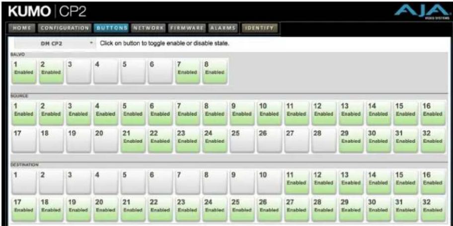
- Web UI buttons that have been disabled will go blank, and the tally lights of the disabled physical buttons on the KUMO CP will go off.
NETWORK Screen
The NETWORK Screen provides access to standard TCP/IP setup fields for network configuration. See "Quick Start Configuration" on page 12 and "Network Configuration In Depth" on page 15 for more information.
IMPORTANT: Do not Update Network Settings with 0.0.0.0 values for either IP Address or Netmask. This will disable the control panel and it will need to be returned to AJA for repair.
Figure 33. KUMO CP Network Setup Screen
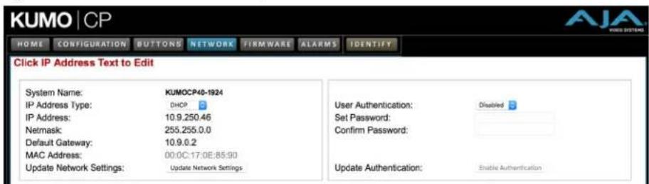
- NETWORK and FIRMWARE tabs – same as KUMO router Network and Firmware settings, see "Network Setup" on page 28, "UPnP Host" on page 30, and "Firmware Updating" on page 30.
User Authentication
This parameter enables or disables an authentication login requirement. See "User Authentication" on page 29 for more information.
FIRMWARE Screen
The FIRMWARE Screen is used to update the KUMO's firmware. See "Firmware Updating" on page 30 for more information.
ALARMS Screen
The Alarms screen reports KUMO error conditions, and allows suppressing selected error messages. See "KUMO Alarms" on page 32 for more information.

The IDENTIFY tab can be used to identify a specific KUMO Control Panel on the network. See "Locating a Specific KUMO Device on the Network" on page 21 for more information.
Overview
This chapter describes using the eMini-Setup application to initially communicate with and configure the KUMO over a direct USB connection. Once configured, the KUMO can be accessed via an Ethernet network using a web browser. Subsequently, that device can then be reconfigured over that network, using its IP address and built in web server.
NOTE: The eMini-Setup application is only used to setup selected Ethernet capable AJA devices, and cannot be used to connect to or setup other AJA Mini-Converters.
The general procedure is:
- Acquire eMini-Setup from the AJA website and install the eMini-Setup application onto a computer.
- Connect the KUMO USB port to that computer's USB port with the supplied USB cable.
- Launch the eMini-Setup application.
- Go to the Network tab where the IP address settings are displayed. You can use the existing DHCP assigned IP address, or it can be changed manually.
Acquiring eMini-Setup
AJA's eMini-Setup application is available for download from the AJA website.
To download the latest eMini-Setup package, which includes the eMini-Setup application and documentation:
- Go to:
https://www.aja.com/family/software#eminisetup - Click the link corresponding to the version you want to download for Mac or Windows.
AJA Documentation
Included with the eMini-Setup download is the AJA device's documentation, which can be accessed from the eMini-Setup UI via the Help/Manual drop-down menu. This manual includes eMini-Setup information.
Documentation can also be accessed directly from the Mac eMini-Setup installer in the Documentation folder.
Documentation included with the eMini-Setup application is the version available at the time of distribution. However, AJA's documentation can be updated regularly, so newer versions may exist.
To download just the latest documentation, go to:
https://www.aja.com/support
Click the product name and open the Manuals link.
PC Installation
To install eMini-Setup on a Windows PC:
- Download the application from the AJA website. See "Acquiring eMini-Setup" on page 41.
- Open the AJA_eMini-Setup_win.zip file.
- Double-click on the AJA_eMini-Setup.msi file.
- The Setup Wizard will guide you through the installation.
Figure 34. eMini-Setup PC Wizard
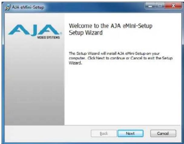
- Click Next to begin. Answer the questions in the subsequent dialogs, including device software installation if displayed. When finished, an AJA eMini-Setup shortcut will be installed on the desktop, and you will be able to locate the eMini-Setup application in the AJA folder in the Programs listing.
NOTE: If the eMini-Setup application already exists on the PC, a different Setup Wizard appears. (In some instances, Windows may require uninstalling an earlier version of eMini-Setup before installing a new version.)
Figure 35. eMini-Setup Wizard, Re-installation

With this screen you can Repair (reinstall) or Remove (uninstall) eMini-Setup on the PC.
Mac Installation
To install the application on a Mac:
NOTE: Mac computers must be Intel-based (G5, G4 and earlier models will not work with eMini-Setup).
- Download the application from the AJA website. See "Acquiring eMini-Setup" on page 41.
- Unzip the file.
- Double-click on the AJA eMini-Setup.dmg file.
- Answer the prompt and a utility program will be launched.
Figure 36. eMini-Setup Mac Installer
![graph TD A["AJA eMini-Setup Docs"] --> B[" AjA eMini-Setup "] C[" AjA eMini-Setup Video Systems"] --> B D[" Because it matters. "] --> E[" Applications "]](/content/2026/05/1041731/images/ea5adfd9b14a0e4444df7dc7007439086813ee874763a171ef4c2a1b93688ff6.jpg)
- To complete the installation drag the "AJA eMini-Setup" icon to the Applications folder.
Running eMini-Setup
Connect your Ethernet capable AJA device to the PC or Mac via the supplied USB cable, and then connect the external power supply (supplied) to that AJA device.
PC Startup
To run eMini-Setup on a PC, double-click on the AJA eMini-Setup icon on your desktop, or open the AJA folder in the program list and click on the AJA eMini-Setup application located inside the eMini-Setup folder.

To run eMini-Setup on a Mac, open the Applications folder and locate the AJA eMini-Setup application. Double-click the application to launch it.
Operating eMini-Setup
The eMini-Setup application provides a graphical user interface for viewing settings, modifying settings, and updating firmware.
Figure 37. Example eMini-Setup Screen

Selecting an AJA device from the pull down menu on the upper right causes eMini-Setup to connect to the selected AJA device.
Version - The version of firmware installed in the AJA device is displayed below the graphic.
Sn - This is the factory set unique serial number of your AJA device. If you ever call AJA Support for service, you may be asked for this number.
A status field at the bottom of the screen shows if the eMini-Setup application is connected and communicating with an AJA device.
File Menu - The File drop-down menu on the eMini-Setup application bar has a Revert to Factory Settings menu item that allows you to change the settings back to the AJA device's factory defaults.
Edit Menu - The Edit drop-down menu has standard Cut, Copy and Paste functions for editing text.
Help Menu - The Help drop-down menu has a link to the AJA device's manual.
NOTE: On a Windows PC, the File, Edit and Help menus reside in the eMini-Setup application window. On a Mac, these menus reside in the application bar above the eMini-Setup application window.
Control Network Tab Screen
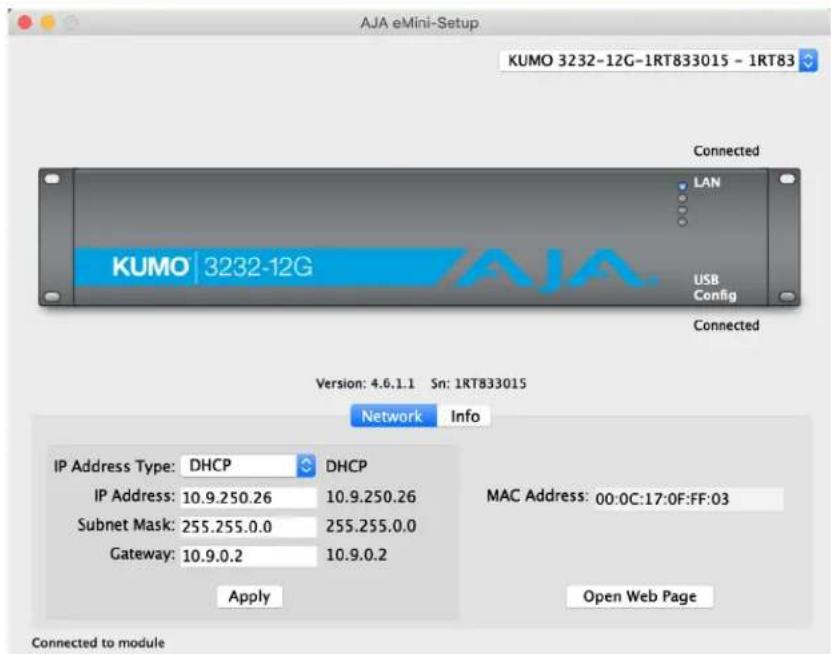
Use this Control Network tab to view and change the network setup on the connected AJA device. The network settings currently being used are shown on the right. You must click the Apply button to initiate any network configuration changes.
IP Address Type - Choose from DHCP or Static IP Address.
IP Address - The current IP Address is displayed. A different IP address can be entered.
Subnet Mask - The current Subnet Mask is displayed. A different subnet mask can be entered.
Gateway - The current Gateway address is displayed. A different gateway address can be entered.
MAC Address - This is the permanent MAC address of the Control LAN Ethernet port of the AJA device.
Open Web Page - Opens the KUMO web interface in a web browser.
Info Tab Screen
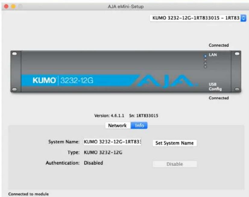
This tab provides basic information about the connected AJA device. This information is mostly useful when calling AJA Support for service or technical support.
System Name - This field allows you to give your AJA device a unique name. This can be useful if you have several attached to a Mac/PC via USB so you can distinguish between them easily. This is also the name that shows up in Zeroconf/Bonjour, uPnP, and the "Other KUMOs" dropdown on the Web UI HOME Screen.
Type - This is the factory set model name of the AJA device.
Authentication - If Authentication has been Enabled on the web browser Access tab, you can disable the security feature by clicking the Disable button.
KUMO 6464-12G Tech Specs
Video Formats
• 270 Mbps, 1.5 Gbps, 3 Gbps, 6 Gbps, 12 Gbps SDI
• 270 Mbps DVB-ASI
Video Input Digital
• 12G-SDI Inputs
• 64x 12G-SDI BNC, SMPTE-259/292/424/2081/2082
Video Output Digital
• 12G-SDI Outputs
• 64x 12G-SDI BNC, SMPTE-259/292/424/2081/2082
- Noninverting
Ancillary Data
• Passes all SDI embedded ancillary data including audio
Salvo
- Up to 8 Salvos can be configured and saved in each KUMO router
Cable Equalization
(Belden 1694A)
• 12 Gbps, up to 50m
- 6 Gbps, up to 90m
• 3 Gbps, up to 140m
• 1.5 Gbps, up to 200m
• 270 Mbps, up to 390m
• Automatic operation
Reclocking
• 270 Mbps, 1.483 Gbps, 1.485 Gbps, 2.967 Gbps, 2.970 Gbps, 5.934 Gbps, 5.940 Gbps, 11.868 Gbps, 11.880 Gbps - Auto Select
Switching Modes
- Single/Normal, Dual, and Quad link modes
• Switches in vertical blanking per SMPTE RP-168
Control Panel Compatibility
- AJA KUMO CP (First 32 I/O in Single/Normal, all I/O in Dual or Quad mode) – 1RU X-Y Ethernet control panel
- AJA KUMO CP2 (Single/Normal, Dual or Quad mode) – 2RU X-Y Ethernet control panel
Reference Input
- External, 2x BNC
- Looping, nonterminating
- Blackburst or tri-level sync
Network Interface
• 1x RJ-45, 10/100/1000 Ethernet
• Supports AJA KUMO Ethernet control panels, direct connect or networked
- Basic support for Grass Valley Native Protocol
- Embedded web server for remote control
USB Interface
- 1x Mini-USB for IP configuration using AJA eMini-Setup
Serial Interface
• 1x DB-9 Female, RS-422
- Basic support for Grass Valley Native Protocol
- 9-pin D-connector pinout is as follows:
| 1 | GND |
| 2 | TX- |
| 3 | RX+ |
| 4 | GND |
5 No Connection
| 6 | GND |
| 7 | TX+ |
| 8 | RX- |
| 9 | GND |
| Shell | GND |
Size (w x d x h)
- 4RU - 17.4" x 1.55" x 7.00" (441.96 x 39.37 x 177.8 mm)
Weight
• 9.2 lbs (4.2 kg)
Power
• External power supply required
- Enclosure: Dual, redundant, 10-14VDC regulated, 4-pin Molex, 50W typical, 72W max.
- AC adapter, included: 100-240VAC, 50/60 Hz, universal input, 84W
- Optional redundant AC adapter sold separately, KUMO-84W-PWR
Environment
- Safe Operating Temperature: 0 to 40 C (32 to 104 F)
- Safe Storage Temperature (Power OFF): -40 to 60 C (-40 to 140 F)
- Operating Relative Humidity: 10-90% noncondensing
- Operating Altitude: <3,000 meters (<10,000 feet)
KUMO 6464 Tech Specs
Video Formats
• 270 Mbps, 1.5 Gbps, 3 Gbps SDI
• 270 Mbps DVB-ASI
Video Input Digital
• 3G-SDI Inputs
• 64x BNC, SMPTE-259/292/424
Video Output Digital
• 3G-SDI Outputs
• 64x BNC, SMPTE-259/292/424
- Noninverting
Ancillary Data
• Passes all SDI embedded ancillary data including audio
Salvo
- Up to 8 Salvos can be configured and saved in each KUMO router
Cable Equalization
(Belden 1694A)
• 3 Gbps, up to 140m
• 1.5 Gbps, up to 200m
• 270 Mbps, up to 390m
- Automatic operation
Reclocking
• 270 Mbps, 1.483 Gbps, 1.485 Gbps, 2.966 Gbps, 2.970 Gbps - Auto Select
Switching Modes
- Single/Normal, Dual, and Quad link modes
- Switches in vertical blanking per SMPTE RP-168
Control Panel Compatibility
- AJA KUMO CP (First 32 I/O in Single/Normal, all I/O in Dual or Quad mode) – 1RU X-Y Ethernet control panel
- AJA KUMO CP2 (Single/Normal, Dual or Quad mode) – 2RU X-Y Ethernet control panel
Reference Input
- External, 2x BNC
- Looping, nonterminating
- Blackburst or tri-level sync
Network Interface
• 1x RJ-45, 10/100/1000 Ethernet
• Supports AJA KUMO Ethernet control panels, direct connect or networked
- Basic support for Grass Valley Native Protocol
- Embedded web server for remote control
USB Interface
- 1x Mini-USB for IP configuration using AJA eMini-Setup
Serial Interface
• 1x DB-9 Female, RS-422
- Basic support for Grass Valley Native Protocol
- 9-pin D-connector pinout is as follows:
| 1 | GND |
| 2 | TX- |
| 3 | RX+ |
| 4 | GND |
5 No Connection
| 6 | GND |
| 7 | TX+ |
| 8 | RX- |
| 9 | GND |
Shell GND
Size (w x d x h)
- 4RU - 17.4" x 1.54" x 7.00" (441.96 x 39.12 x 177.8 mm)
Weight
• 9.2 lbs (4.2 kg)
Power
• External power supply required
- Enclosure: Dual, redundant, 10-14VDC regulated, 4-pin Molex, 32W typical, 36W max.
- AC adapter, included: 100-240VAC, 50/60 Hz, universal input, 60W
- Optional redundant AC adapter sold separately, KUMO-PWR
Environment
- Safe Operating Temperature: 0 to 40 C (32 to 104 F)
- Safe Storage Temperature (Power OFF): -40 to 60 C (-40 to 140 F)
- Operating Relative Humidity: 10-90% noncondensing
- Operating Altitude: <3,000 meters (<10,000 feet)
KUMO 3232-12G Tech Specs
Video Formats
• 270 Mbps, 1.5 Gbps, 3 Gbps, 6 Gbps, 12 Gbps SDI
• 270 Mbps DVB-ASI
Video Input Digital
• 12G-SDI Inputs
• 32x 12G-SDI BNC, SMPTE-259/292/424/2081/2082
Video Output Digital
• 12G-SDI Outputs
• 32x 12G-SDI BNC, SMPTE-259/292/424/2081/2082
- Noninverting
Ancillary Data
• Passes all SDI embedded ancillary data including audio
Salvo
- Up to 8 Salvos can be configured and saved in each KUMO router
Cable Equalization
(Belden 1694A)
• 12 Gbps, up to 50m
- 6 Gbps, up to 90m
• 3 Gbps, up to 140m
• 1.5 Gbps, up to 200m
• 270 Mbps, up to 390m
- Automatic operation
Reclocking
- 270 Mbps, 1.483 Gbps, 1.485 Gbps, 2.967 Gbps, 2.970 Gbps, 5.934 Gbps, 5.940 Gbps, 11.868 Gbps, 11.880 Gbps - Auto Select
Switching Modes
- Single/Normal, Dual, and Quad link modes
- Switches in vertical blanking per SMPTE RP-168
Control Panel Compatibility
- AJA KUMO CP – 1RU X-Y Ethernet control panel
- AJA KUMO CP2 – 2RU X-Y Ethernet control panel
Reference Input
- External, 2x BNC
- Looping, nonterminating
- Blackburst or tri-level sync
Network Interface
• 1x RJ-45, 10/100/1000 Ethernet
• Supports AJA KUMO Ethernet control panels, direct connect or networked
- Basic support for Grass Valley Native Protocol
- Embedded web server for remote control
USB Interface
- 1x Mini-USB for IP configuration using AJA eMini-Setup
Serial Interface
• 1x DB-9 Female, RS-422
- Basic support for Grass Valley Native Protocol
- 9-pin D-connector pinout is as follows:
| 1 | GND |
| 2 | TX- |
| 3 | RX+ |
| 4 | GND |
5 No Connection
| 6 | GND |
| 7 | TX+ |
| 8 | RX- |
| 9 | GND |
Shell GND
Size (w x d x h)
- 2RU - 17.4" x 1.54" x 3.50" (441.96 x 39.12 x 88.9 mm)
Weight
• 4.6 lb (2.1 kg)
Power
• External power supply required
- Enclosure: Dual, redundant, 10-14VDC regulated, 4-pin Molex, 24W typical, 25.2W max.
- AC adapter, included: 100-240VAC, 50/60 Hz, universal input, 60W
- Optional redundant AC adapter sold separately, KUMO-PWR
Environment
- Safe Operating Temperature: 0 to 40 C (32 to 104 F)
- Safe Storage Temperature (Power OFF): -40 to 60 C (-40 to 140 F)
- Operating Relative Humidity: 10-90% noncondensing
- Operating Altitude: <3,000 meters (<10,000 feet)
KUMO 3232 Tech Specs
Video Formats
• 270 Mbps, 1.5 Gbps, 3 Gbps SDI
• 270 Mbps DVB-ASI
Video Input Digital
• 3G-SDI Inputs
• 32x BNC, SMPTE-259/292/424
Video Output Digital
• 3G-SDI Outputs
• 32x BNC, SMPTE-259/292/424
- Noninverting
Ancillary Data
• Passes all SDI embedded ancillary data including audio
Salvo
- Up to 8 Salvos can be configured and saved in each KUMO router
Cable Equalization
(Belden 1694A)
• 3 Gbps, up to 140m
• 1.5 Gbps, up to 200m
• 270 Mbps, up to 390m
- Automatic operation
Reclocking
• 270 Mbps, 1.483 Gbps, 1.485 Gbps, 2.966 Gbps, 2.970 Gbps - Auto Select
Switching Modes
- Single/Normal, Dual, and Quad link modes
- Switches in vertical blanking per SMPTE RP-168
Control Panel Compatibility
- AJA KUMO CP – 1RU X-Y Ethernet control panel
- AJA KUMO CP2 – 2RU X-Y Ethernet control panel
Reference Input
- External, 2x BNC
- Looping, nonterminating
- Blackburst or tri-level sync
Network Interface
• 1x RJ-45, 10/100/1000 Ethernet
• Supports AJA KUMO Ethernet control panels, direct connect or networked
- Basic support for Grass Valley Native Protocol
- Embedded web server for remote control
USB Interface
- 1x Mini-USB for IP configuration using AJA eMini-Setup
Serial Interface
• 1x DB-9 Female, RS-422
- Basic support for Grass Valley Native Protocol
- 9-pin D-connector pinout is as follows:
1 GND
2 TX-
3 RX+
4 GND
5 No Connection
6 GND
7 TX+
8 RX-
9 GND
Shell GND
Size (w x d x h)
- 2RU - 17.4" x 1.54" x 3.5" (441.96 x 39.12 x 88.9 mm)
Weight
• 4.6 lb (2.1 kg)
Power
• External power supply required
- Enclosure: Dual, redundant, 10-14VDC regulated, 4-pin Molex, 18W typical, 43.2W max.
- AC adapter, included: 100-240VAC, 50/60 Hz, universal input, 60W
- Optional redundant AC adapter sold separately, KUMO-PWR
Environment
- Safe Operating Temperature: 0 to 40 C (32 to 104 F)
- Safe Storage Temperature (Power OFF): -40 to 60 C (-40 to 140 F)
- Operating Relative Humidity: 10-90% noncondensing
- Operating Altitude: <3,000 meters (<10,000 feet)
KUMO 1616-12G Tech Specs
Video Formats
• 270 Mbps, 1.5 Gbps, 3 Gbps, 6 Gbps, 12 Gbps SDI
• 270 Mbps DVB-ASI
Video Input Digital
• 12G-SDI Inputs
• 16x 12G-SDI BNC, SMPTE-259/292/424/2081/2082
Video Output Digital
• 12G-SDI Outputs
• 16x 12G-SDI BNC, SMPTE-259/292/424/2081/2082
- Noninverting
Ancillary Data
• Passes all SDI embedded ancillary data including audio
Salvo
- Up to 8 Salvos can be configured and saved in each KUMO router
Cable Equalization
(Belden 1694A)
• 12 Gbps, up to 50m
- 6 Gbps, up to 90m
• 3 Gbps, up to 140m
• 1.5 Gbps, up to 200m
• 270 Mbps, up to 390m
• Automatic operation
Reclocking
• 270 Mbps, 1.483 Gbps, 1.485 Gbps, 2.967 Gbps, 2.970 Gbps, 5.934 Gbps, 5.940 Gbps, 11.868 Gbps, 11.880 Gbps - Auto Select
Switching Modes
- Single/Normal, Dual, and Quad link modes
- Switches in vertical blanking per SMPTE RP-168
Control Panel Compatibility
- AJA KUMO CP – 1RU X-Y Ethernet control panel
- AJA KUMO CP2 – 2RU X-Y Ethernet control panel
Reference Input
- External, 2x BNC
- Looping, nonterminating
- Blackburst or tri-level sync
Network Interface
• 1x RJ-45, 10/100/1000 Ethernet
• Supports AJA KUMO Ethernet control panels, direct connect or networked
- Basic support for Grass Valley Native Protocol
- Embedded web server for remote control
USB Interface
- 1x Mini-USB for IP configuration using AJA eMini-Setup
Serial Interface
• 1x DB-9 Female, RS-422
- Basic support for Grass Valley Native Protocol
- 9-pin D-connector pinout is as follows:
1 GND
2 TX-
3 RX+
4 GND
5 No Connection
6 GND
7 TX+
8 RX-
9 GND
Shell GND
Size (w x d x h)
- 1RU - 17.4" x 1.54" x 1.75" (441.96 x 39.12 x 44.45 mm)
Weight
• 1.4 lb (0.7 kg)
Power
• External power supply required
- Enclosure: Dual, redundant, 10-14VDC regulated, 4-pin Molex, 16W typical, 18W max.
- AC adapter, included: 100-240VAC, 50/60 Hz, universal input, 60W
- Optional redundant AC adapter sold separately, KUMO-PWR
Environment
- Safe Operating Temperature: 0 to 40 C (32 to 104 F)
- Safe Storage Temperature (Power OFF): -40 to 60 C (-40 to 140 F)
- Operating Relative Humidity: 10-90% noncondensing
- Operating Altitude: <3,000 meters (<10,000 feet)
KUMO 1616 Tech Specs
Video Formats
• 270 Mbps, 1.5 Gbps, 3 Gbps SDI
• 270 Mbps DVB-ASI
Video Input Digital
• 3G-SDI Inputs
• 16x BNC, SMPTE-259/292/424
Video Output Digital
• 3G-SDI Outputs
• 16x BNC, SMPTE-259/292/424
- Noninverting
Ancillary Data
• Passes all SDI embedded ancillary data including audio
Salvo
- Up to 8 Salvos can be configured and saved in each KUMO router
Cable Equalization
(Belden 1694A)
• 3 Gbps, up to 140m
• 1.5 Gbps, up to 200m
• 270 Mbps, up to 390m
• Automatic operation
Reclocking
• 270 Mbps, 1.483 Gbps, 1.485 Gbps, 2.966 Gbps, 2.970 Gbps - Auto Select
Switching Modes
- Single/Normal, Dual, and Quad link modes
• Switches in vertical blanking per SMPTE RP-168
Control Panel Compatibility
- AJA KUMO CP – 1RU X-Y Ethernet control panel
- AJA KUMO CP2 – 2RU X-Y Ethernet control panel
Reference Input
- External, 2x BNC
- Looping, nonterminating
- Blackburst or tri-level sync
Network Interface
• 1x RJ-45, 10/100/1000 Ethernet
• Supports AJA KUMO Ethernet control panels, direct connect or networked
- Basic support for Grass Valley Native Protocol
- Embedded web server for remote control
USB Interface
- 1x Mini-USB for IP configuration using AJA eMini-Setup
Serial Interface
• 1x DB-9 Female, RS-422
- Basic support for Grass Valley Native Protocol
- 9-pin D-connector pinout is as follows:
| 1 | GND |
| 2 | TX- |
| 3 | RX+ |
| 4 | GND |
5 No Connection
| 6 | GND |
| 7 | TX+ |
| 8 | RX- |
| 9 | GND |
| Shell | GND |
Size (w x d x h)
- 1RU - 17.4" x 1.54" x 1.75" (441.96 x 39.12 x 44.45 mm)
Weight
• 1.4 lb (0.7 kg)
Power
• External power supply required
- Enclosure: Dual, redundant, 10-14VDC regulated, 4-pin Molex, 13W typical, 21.6W max.
- AC adapter, included: 100-240VAC, 50/60 Hz, universal input, 60W
- Optional redundant AC adapter sold separately, KUMO-PWR
Environment
- Safe Operating Temperature: 0 to 40 C (32 to 104 F)
- Safe Storage Temperature (Power OFF): -40 to 60 C (-40 to 140 F)
- Operating Relative Humidity: 10-90% noncondensing
- Operating Altitude: <3,000 meters (<10,000 feet)
KUMO 1604 Tech Specs
Video Formats
• 270 Mbps, 1.5 Gbps, 3 Gbps SDI
• 270 Mbps DVB-ASI
Video Input Digital
• 3G-SDI Inputs
• 16x BNC, SMPTE-259/292/424
Video Output Digital
• 3G-SDI Outputs
• 4x BNC, SMPTE-259/292/424
- Noninverting
Ancillary Data
• Passes all SDI embedded ancillary data including audio
Salvo
- Up to 8 Salvos can be configured and saved in each KUMO router
Cable Equalization
(Belden 1694A)
• 3 Gbps, up to 140m
• 1.5 Gbps, up to 200m
• 270 Mbps, up to 390m
• Automatic operation
Reclocking
• 270 Mbps, 1.483 Gbps, 1.485 Gbps, 2.966 Gbps, 2.970 Gbps - Auto Select
Switching Modes
- Single/Normal, Dual, and Quad link modes
- Switches in vertical blanking per SMPTE RP-168
Control Panel Compatibility
- AJA KUMO CP – 1RU X-Y Ethernet control panel
- AJA KUMO CP2 – 2RU X-Y Ethernet control panel
Reference Input
- External, 2x BNC
- Looping, nonterminating
- Blackburst or tri-level sync
Network Interface
• 1x RJ-45, 10/100/1000 Ethernet
• Supports AJA KUMO Ethernet control panels, direct connect or networked
- Basic support for Grass Valley Native Protocol
- Embedded web server for remote control
USB Interface
- 1x Mini-USB for IP configuration using AJA eMini-Setup
Serial Interface
• 1x DB-9 Female, RS-422
- Basic support for Grass Valley Native Protocol
- 9-pin D-connector pinout is as follows:
| 1 | GND |
| 2 | TX- |
| 3 | RX+ |
| 4 | GND |
| 5 | No Connection |
| 6 | GND |
| 7 | TX+ |
| 8 | RX- |
| 9 | GND |
| Shell | GND |
Size (w x d x h)
- 1RU - 17.4" x 1.54" x 1.75" (441.96 x 39.12 x 44.45 mm)
Weight
• 1.2 lb (0.6 kg)
Power
• External power supply required
- Enclosure: Dual, redundant, 10-14VDC regulated, 4-pin Molex, 7W typical, 9.6W max.
- AC adapter, included: 100-240VAC, 50/60 Hz, universal input, 60W
- Optional redundant AC adapter sold separately, KUMO-PWR
Environment
- Safe Operating Temperature: 0 to 40 C (32 to 104 F)
- Safe Storage Temperature (Power OFF): -40 to 60 C (-40 to 140 F)
- Operating Relative Humidity: 10-90% noncondensing
- Operating Altitude: <3,000 meters (<10,000 feet)
KUMO CP2 Tech Specs
User Interface
- 80 buttons with removable overcap for lens chips
- Includes factory installed lens chip set
- High and Low button tally indication, configurable brightness
• Controls up to four KUMO routers - Panel Lock feature
- Destination Lock feature
Router Support
• KUMO 1604
• KUMO 1616
• KUMO 3232
• KUMO 6464
• KUMO 1616-12G
• KUMO 3232-12G
• KUMO 6464-12G
Salvo
- 8 Salvos buttons can be enabled to trigger a KUMO router's configured salvos.
Network Interface
• 1x RJ-45, 10/100/1000 Ethernet
- Embedded web server for remote control
USB Interface
- 1x Mini-USB for IP configuration using AJA eMini-Setup
Size (w x d x h)
- 2RU - 17.4" x 1.3" x 3.5" (441.96 x 33.02 x 88.90 mm)
Weight
• 2.1 lb (1.0 kg)
Power
• External power supply required
- Enclosure: Dual, redundant, 10-14VDC regulated, 4-pin Molex, 4W typical, 9.6W max.
- AC adapter, included: 100-240VAC, 50/60 Hz, universal input, 60W
- Optional redundant AC adapter sold separately, KUMO-PWR
Environment
- Safe Operating Temperature: 0 to 40 C (32 to 104 F)
- Safe Storage Temperature (Power OFF): -40 to 60 C (-40 to 140 F)
- Operating Relative Humidity: 10-90% noncondensing
- Operating Altitude: <3,000 meters (<10,000 feet)
KUMO CP Tech Specs
User Interface
- 40 buttons with removable overcap for lens chips
- Includes factory installed lens chip set
- High and Low button tally indication, configurable brightness
• Controls up to four KUMO routers - Panel Lock feature
- Destination Lock feature
Router Support
• KUMO 1604
• KUMO 1616
• KUMO 3232
• KUMO 6464 (First 32 I/O in Single/Normal Mode)
• KUMO 1616-12G
• KUMO 3232-12G
• KUMO 6464-12G (First 32 I/O in Single/Normal Mode)
Network Interface
• 1x RJ-45, 10/100/1000 Ethernet
- Embedded web server for remote control
USB Interface
- 1x Mini-USB for IP configuration using AJA eMini-Setup
Size (w x d x h)
- 1RU - 17.4" x 1.3" x 1.75" (441.96 x 33.02 x 44.45 mm)
Weight
• 1.2 lb (0.6 kg)
Power
• External power supply required
- Enclosure: Dual, redundant, 10-14VDC regulated, 4-pin Molex, 2.5W, typical, 6W max.
- AC adapter, included: 100-240VAC, 50/60 Hz, universal input, 60W
- Optional redundant AC adapter sold separately, KUMO-PWR
Environment
- Safe Operating Temperature: 0 to 40 C (32 to 104 F)
- Safe Storage Temperature (Power OFF): -40 to 60 C (-40 to 140 F)
- Operating Relative Humidity: 10-90% noncondensing
- Operating Altitude: <3,000 meters (<10,000 feet)
GVG Native Protocol Support
Introduced with v2.0 firmware, KUMO provides basic support for the GVG Native Protocol, aka Series 7000 Native Protocol. GVG Native Protocol, using:
• 1 serial connection via RS-422 with a 9-pin connector
• TCP/Ethernet for up to 32 connections
For more information, refer to Grass Valley documentation at:
http://grassvalley.jp/pdf/RoutingProductsProtocolManual_2.pdf
NP Commands Supported
Background:
- BK, I; Connect, heartbeat
- BK, N; Gets system name
- BK, T; Gets software title
- BK, t; Gets protocol software
- BK, R; Gets software version
- BK, d; Gets device name
- BK, F; Gets source, destination or salvo name changes
- BK, E; Sets or returns status of Level 4 Echo
Queries:
- QI, {dstIndex = 1..maxDst},{lvllIndex = 0}; Gets dest status by index and level
- Qi, {dstIndex = 1..maxDst},{lvllndex = 0}; Gets dest status by Index and level
- QN, S; Gets all srcs by name
• QN, IS; Gets all srcs, name & index
• QN, D; Gets all dests, names - QN, ID; Gets all dests, name & index
- QN, L; Gets levels (hard coded as "Kumo_Lev0")
- QD, {destname}; Gets: protect {On/Off}, chop{=OFF}, {sourceName}, level{=lev0}
- Qd, {destname}; Gets: protect {On/Off}, chop{=OFF}, {sourceName}, level{=lev0}
Control:
- TD, {destname,srcname}; Takes by name
- TI, {dstIndex = 1 ..maxDst}, {srcIndex = 1 ..maxSrc}; Takes by index
- TS, {salvo_name}; Takes Salvo
- PR, {destname, levelmask}; Sets lock for given dest
- UP, {destname, levelmask}; Unsets lock for given dest
RS-422 Control Specifications (Routers)
NOTE: All KUMO Routers support RS-422 control. KUMO Control Panels do not support RS-422 control.
- Baud Rate: 38400
- Parity: None
- Stop Bit: 1
- Data Bits: 8
Serial Interface
• 1x DB-9 Female, RS-422
- Grass Valley Native Protocol
- 9-pin D-connector pinout is as follows:
| 1 | GND |
| 2 | TX- |
| 3 | RX+ |
| 4 | GND |
5 No Connection
| 6 | GND |
| 7 | TX+ |
| 8 | RX- |
| 9 | GND |
| Shell | GND |
NOTE: Older KUMO 1604, 1616, and 3232 routers with a serial number ending in -R0 have different pinouts. See "Older Model RS-422 Adapter" on page 9 for more information.
Appendix B – Safety & Compliance
Federal Communications Commission (FCC) Compliance Notices
Class A Interference Statement
This equipment has been tested and found to comply with the limits for a Class A digital device, pursuant to Part 15, Subpart B of the FCC Rules. These limits are designed to provide reasonable protection against harmful interference in a commercial installation. This equipment generates, uses, and can radiate radio frequency energy and, if not installed and used in accordance with the instructions, may cause harmful interference to radio communications. However, there is no guarantee that interference will not occur in a particular installation. Operation of this equipment in a residential area is likely to cause harmful interference in which case the user will be required to correct the interference at his own expense. If this equipment does cause harmful interference to radio or television reception, which can be determined by turning the equipment off and on, the user is encouraged to try to correct the interference by one or more of the following measures:
- Reorient or relocate the receiving antenna.
- Increase the separation between the equipment and receiver.
- Connect the equipment into an outlet on a circuit different from that to which the receiver is connected.
- Consult the dealer or an experienced radio/TV technician for help.
FCC Caution
This device complies with Part 15 of the FCC Rules. Operation is subject to the following two conditions: (1) This device may not cause harmful interference, and (2) this device must accept any interference received, including interference that may cause undesired operation.
Canadian ICES Statement
Canadian Department of Communications Radio Interference Regulations
This digital apparatus does not exceed the Class A limits for radio-noise emissions from a digital apparatus as set out in the Radio Interference Regulations of the Canadian Department of Communications. This Class A digital apparatus complies with Canadian ICES-003.
European Union and European Free Trade Association (EFTA) Regulatory Compliance
This equipment may be operated in the countries that comprise the member countries of the European Union and the European Free Trade Association. These countries, listed in the following paragraph, are referred to as The European Community throughout this document:
AUSTRIA, BELGIUM, BULGARIA, CYPRUS, CZECH REPUBLIC, DENMARK, ESTONIA, FINLAND, FRANCE, GERMANY, GREECE, HUNGARY, IRELAND, ITALY, LATVIA, LITHUANIA, LUXEMBOURG, MALTA, NETHERLANDS, POLAND, PORTUGAL, ROMANIA, SLOVAKIA, SLOVENIA, SPAIN, SWEDEN, UNITED KINGDOM, ICELAND, LICHTENSTEIN, NORWAY, SWITZERLAND
Declaration of Conformity
Marking by this symbol indicates compliance with the Essential Requirements of the EMC Directive of the European Union 2014/30/EU.

This equipment meets the following conformance standards:
Safety
EN 62368-1: 2014 + A11 (T-Mark License)
IEC 62368-1: 2014 (CB Scheme Certificate)
Emissions
EN 55032: 2012 + AC: 2013, CISPR 32: 2015,
EN 61000-3-2: 2014, EN 61000-3-3: 2013
Immunity
EN 55103-2: 2009, EN 61000-4-2: 2009, EN 61000-4-3: 2006 + A1: 2008 + A2: 2010,
EN 61000-4-4: 2012, EN 61000-4-5: 2014 + A1: 2017, EN 61000-4-6: 2013,
EN 61000-4-11:2020
Environments: E2, E3 and E4
The product is also licensed for additional country specific standards as required for the International Marketplace

Warning! This is a Class A product. In a domestic environment, this product may cause radio interference, in which case, the user may be required to take appropriate measures.
The product is also licensed for additional country specific standards as required
Recycling Notice

This symbol on the product or its packaging indicates that this product must not be disposed of with your other household waste. Instead, it is your responsibility to dispose of your waste equipment by handing it over to a designated collection point for the recycling of waste electrical and electronic equipment. The separate collection and recycling of your waste equipment at the time of disposal will help conserve natural resources and ensure that it is recycled in a manner that protects human health and the environment. For more information about where you can drop off your waste for recycling, please contact your local authority, or where you purchased your product.
Korea KCC Compliance Statement
사용자 안내문
Taiwan Compliance Statement
警告使用者:
This is a Class A product based on the standard of the Bureau of Standards, Metrology and Inspection (BSMI) CNS 13438, Class A. In a domestic environment this product may cause radio interference in which case the user may be required to take adequate measures.
Japan Compliance Statement
This is a Class A product based on the standard of the VCCI Council (VCCI-32: 2016). If this equipment is used in a domestic environment, radio interference may occur, in which case, the user may be required to take corrective actions.
Translated Warning and Caution Messages
The following caution statements, warning conventions, and warning messages apply to this product and manual.

Warning Symbol

Caution Symbol
Before Operating Please Read These Instructions

Warning! Read and follow all warning notices and instructions marked on the product or included in the documentation.
Warning! Do not use this device near water and clean only with a dry cloth.
Warning! Do not block any ventilation openings. Install in accordance with the manufacturer's instructions.
Warning! Do not install near any heat sources such as radiators, heat registers, stoves, or other apparatus (including amplifiers) that produce heat.
Warning! Unplug this device during lightning storms or when unused for long periods of time.
Warning! Do not open the chassis. There are no user-serviceable parts inside. Opening the chassis will void the warranty unless performed by an AJA service center or licensed facility.
Warning! Refer all servicing to qualified service personnel. Servicing is required when the device has been damaged in any way, such as power-supply cord or plug is damaged, liquid has been spilled or objects have fallen into the device, the device has been exposed to rain or moisture, does not operate normally, or has been dropped.
Warning! Do not defeat the safety purpose of the polarized or grounding-type plug. A polarized plug has two blades with one wider than the other. A grounding type plug has two blades and a third grounding prong. The wide blade or the third prong are provided for your safety. If the provided plug does not fit into your outlet, consult an electrician for replacement of the obsolete outlet.
Warning! Since the Mains plug is used as the disconnection for the device, it must remain readily accessible and operable.
Warning! Protect the power cord from being walked on or pinched particularly at plugs, convenience receptacles, and the point where they exit from the device.
Warning! Disconnect the external AC power supply line cord(s) from the mains power before moving the unit.
Caution! To meet safety regulations for leakage current when using redundant power supplies, connect the KUMO dual power supplies to separate branch circuits.
Cautionl KUMO is designed to take advantage of its chassis to aid in cooling. It is common and expected for the densely populated 1616 chassis to have a warm front panel in normal, active operating conditions.
Caution! When attaching KUMO to a standard Static IP LAN, you must configure KUMO components with a new, unique IP address. You should first talk to your network administrator and find out how it should be connected (TCP/IP Static IP or DHCP). Your IT department will be able to supply the information you need to install KUMO on a LAN. Methods for assigning Static IP addressing are discussed in the KUMO Installation and Operation manual.
Warranty and Liability Information
Limited Warranty on Hardware
AJA Video Systems, Inc. (AJA Video) warrants that the hardware product, not including software components, will be free from defects in materials and workmanship for a period of five years from the date of purchase. AJA Video provides a separate software warranty as part of the license agreement applicable to software components.
If the Customer brings a valid claim under this limited warranty for a hardware product (hereafter, a "product") during the applicable warranty period, AJA Video will, at its sole option and as the Customer's sole remedy for breach of the above warranty, provide one of the following remedies:
- Repair or facilitate the repair the product within a reasonable period of time, free of charge for parts and labor.
- Replace the product with a direct replacement or with a product that performs substantially the same function as the original product.
- Issue a refund of the original purchase price less depreciation to be determined based on the age of the product at the time remedy is sought under this limited warranty.
To obtain service under this warranty, the Customer must notify AJA Video of the defect before expiration of the warranty period and make suitable arrangements for the performance of service by contacting AJA Video support through the channels set forth on the support contacts web page at https://www.aja.com/support. Except as stated, the Customer shall bear all shipping, packing, insurance and other costs, excluding parts and labor, to effectuate repair. Customer shall pack and ship the defective product to a service center designated by AJA Video, with shipping charges prepaid. AJA Video shall pay to return the product to Customer, but only if to a location within the country in which the AJA Video service center is located. SOME JURISDICTIONS DO NOT ALLOW THE EXCLUSION OF IMPLIED WARRANTIES OR LIMITATIONS ON APPLICABLE STATUTORY RIGHTS OF A CONSUMER, SO SOME OR ALL OF THE TERMS OF THIS PARAGRAPH MAY NOT APPLY TO YOU.
Limitation of Liability
Under no circumstances shall AJA video BE LIABLE IN ANY WAY FOR ANY LOST, CORRUPTED OR DESTROYED DATA, FOOTAGE OR WORK, OR FOR ANY OTHER INDIRECT, SPECIAL, INCIDENTAL OR CONSEQUENTIAL DAMAGES OR LOST PROFITS, OR FOR ANY THIRD PARTY CLAIM, IN CONNECTION WITH THE PRODUCT, WHETHER RESULTING FROM DEFECTS IN THE PRODUCT, SOFTWARE OR HARDWARE FAILURE, OR ANY OTHER CAUSE WHATSOEVER, EVEN IF AJA VIDEO HAS BEEN ADVISED OF THE POSSIBILITY OF SUCH DAMAGES. AJA VIDEO'S LIABILITY IN CONNECTION WITH THE PRODUCT SHALL UNDER NO CIRCUMSTANCES EXCEED THE PURCHASE PRICE PAID FOR THE PRODUCT. The foregoing limitations apply even if any remedy set forth in this LIMITED WARRANTY fails of its essential purpose. SOME JURISDICTIONS DO NOT ALLOW THE LIMITATION OF LIABILITY FOR PERSONAL INJURY, OR OF INCIDENTAL OR CONSEQUENTIAL DAMAGES, SO SOME OR ALL OF THE TERMS OF THIS PARAGRAPH MAY NOT APPLY TO YOU.
Governing Law and Language; Your Rights
This limited warranty is the only warranty provided by AJA Video on the hardware product. It supersedes all prior or contemporaneous understandings regarding such subject matter. No amendment to or modification of this warranty will be binding unless in writing and signed by AJA Video. The laws of the State of California, USA will govern this warranty and any dispute arising from it. Any translation of this Agreement is intended for convenience and to meet local requirements and in the event of a dispute between the English and any non-English versions, the English version of this warranty will govern. This limited warranty gives you specific legal rights and you may have other rights that vary from jurisdiction to jurisdiction, some of which are noted above.
A
Access Settings 26
AJA Documentation 41
AJA Support 2
Alarm
Over Temperature 33
Power Supply Error 32
Reference 32
Suppress 33
Authentication 29
Disabling 46
Auto Configure 12, 38
Auto Configured LAN 16
Auto Discovery 13
Bonjour on Mac 13
UPnP on PC 14
B
BNC Connectors
Dual Mode 25
Quad Mode 25
Bonjour 10, 15
Auto Discovery on Mac 13
Button Disable Feature 38
Button Key Cap 35
Button Settings 25
BUTTONS Screen 38
C
Cable
USB Cable Supplied 43
Cable Length Setting 26
Cable Routing 12
Cat 5 Cable
Cross-Over 12, 16
Straight-Through 12, 16
Closed Network 16
Coloring Web Browser Buttons 25
Color Settings 25
Configuration
Initial 41
Mac Auto Discovery 13
Mac Using Static IP 17
Network 15
Quick Start 12
Static IP 20
Windows Auto Discovery 14
Windows Using Stattic IP 18
Configuration Screen
KUMO CP 38
KUMO Router 23
CONFIGURATION Screen 38
Control Network Tab Screen 45
Control Panel Button
Disabling 38
Cooling Requirements 12
Cooling Vents 12
Custom Lens Chips 35
D
Delegation Button 36
Destination Lock 26,36
Removing 36
Destination Output) Button 22
Device Selection
KUMO Home Screen 22
DHCP 13, 15
Assigned IP Address 14, 41
Default Configuration 19
IP Address 45
Disabling Control Panel Button 38
Display Intensity 38
DNS Server 15
Documentation 41
Download KUMO Firmware 30
Dual Mode 9
BNC Connectors 25
E
Edit Menu 44
eMini-Setup 41
Acquiring 41
Downloading 41
Installing 42
Operating 44
Overview 41
Running 43
Screen 44
Enable Exit Page Warning 27
Ethernet Hub 16
Ethernet Switch 16
F
Features 7
File Menu 44
Firmware
Version Installed 44
Firmware Safeboot Reset 32
Firmware Update 30
Firmware Version Number 30
G
GVG Native Protocol 10, 61
H
Help Menu 44
Hide 26
Hide Destination 26
HOME Screen
KUMO Router 23
|
Identify LED 8, 21, 35
IDENTIFY Tab 21
Info Tab Screen 46
Installation Summary 11
Installing
eMini-Setup on Mac 43
eMini-Setup on Windows 42
Installing KUMO Firmware 31
IP Address
Accessing Settings 14, 41
Choosing DHCP or Static 45
Temporary Static 14
Using to Access Web UI 41
IP Reset
Temporary Static IP 37
K
Key Cap 35
KUMO Device Selection 22
KUMO Firmware
Download 30
KUMO Internal Web Server 22
L
LAN 15
LAN Connection 16
Lens Chips 35
Lock 26
Long Cable Setting 26
M
MAC Address 28
N
Navigation Bar 22
Network Auto Discovery 13
Network Configuration 15
Applying Changes 45
Network Configuration via USB 14
Network Failure
Pink Router Delegation Button 36
NETWORK Screen 39
Normal Mode 9
O
Over Temperature Alarm 33
Overview 6
P
Packing Contents 11
Panel Lock 35, 36
Password Reset
KUMO CP 30
KUMO Router 29
Performing a Salvo 23, 35
Performing a Take 23, 35
Pink Router Delegation Button 36
Power Connector 8
Power Loss Recovery 8
Power Requirements 12
Power Supply
External 8
Power Supply Alarm 32
Power Supply Module 8
Q
Quad Mode 9
BNC Connectors 25
Quick Start 12
R
REF BNC Connector 9
Reference Alarm 32
Requirements
USB Port 41
Reset Button 9
Reset to Factory Default Firmware 37
Reset to Factory Defaults 38
RJ-45 Connector 8
Router Configuration Screen 23
Router Delegation Buttons 36
RS-422 9,62
RS-422 Adapter 9
S
Safari 13
Safeboot Reset 32
Salvo
Taking 23, 35
Salvo Button 22, 37
Salvo Configuration 28
Serial Number 44
SHIFT DEST Button 37
Shifted Destination Selection 37
Shifted Source Selection 37
SHIFT SRC Button 37
Signal Switching Mode 24
Software Update Files 30
Source (Input) Button 22
Space Requirements 11
Standard TCP-IP Network 16
Static IP Address
Temporary 14
Static IP Configuration 20
Status
eMini-Setup Application 44
Subnet Mask
eMini-Setup 45
Suppress Alarm 33
System Name Field 28
T
Take
Performing 23, 35
Taking a Salvo 23, 35
TCP/IP 19
TCP/IP Setup 28, 39
Technical Support 2
Temporary Static IP 14
Procedure 14
U
Update Network Settings 28
Uploading KUMO Firmware 31
UPnP 10, 15
Auto Discovery on PC 14
USB Cable
Running eMini-Setup 43
USB Network Configuration 14
User Authentication 29
W
WAN 19
Web Browser
Accessing Unit Via IP Address 41
Web Browser Interface
Coloring Buttons 25
Navigation Bar 22
Web Browser Operation 22
Web Server
Built In 41
KUMO Internal 22
Z
Zeroconfig 15
ZIP File 30
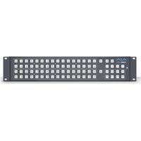
- SDI ROUTERS AND CONTROL PANELS
- INSTALLATION AND OPERATION GUIDE
- TRADEMARKS
- COPYRIGHT
- CONTACTING AJA SUPPORT
- CONTENTS
- NOTICES 2
- CHAPTER 1 – INTRODUCTION .....6
- CHAPTER 2 – INSTALLATION ..... 11
- CHAPTER 3 – ROUTER WEB BROWSER USER INTERFACE
- CHAPTER 1 – INTRODUCTION
- OVERVIEW
- KUMO FEATURES
- KUMO ROUTER CONNECTIONS
- PS1 & PS2 POWER CONNECTORS
- POWER LOSS RECOVERY
- RJ-45 ETHERNET CONNECTOR
- IDENTIFY LED
- RESET BUTTON
- REF BNC CONNECTOR
- VIDEO INPUTS AND OUTPUTS
- NORMAL MODE
- DUAL AND QUAD MODES
- RS-422 CONNECTOR
- OLDER MODEL RS-422 ADAPTER
- KUMO CONTROL AND MONITORING
- DEFAULT NETWORK SETTINGS
- IN THIS MANUAL
- WHAT'S IN THE BOX
- KUMO CHASSIS INSTALLATION
- SPACE REQUIREMENTS
- COOLING REQUIREMENTS
- POWER REQUIREMENTS
- PHYSICAL EQUIPMENT SETUP
- QUICK START CONFIGURATION
- DEFAULT AUTO CONFIGURE KUMO ROUTER AND CONTROL PANEL
- DHCP ON AN EXISTING NETWORK
- COMPUTER AUTO DISCOVERY
- OLDER MACOS CONFIGURATION WITH SAFARI BROWSER USING BONJOUR
- WINDOWS PC CONFIGURATION USING UPNP
- NETWORK CONFIGURATION VIA USB
- KUMO TEMPORARY STATIC IP ADDRESS
- NETWORK CONFIGURATION IN DEPTH
- LAN CONNECTION USING A HUB OR SWITCH
- SETUP AND CONTROL METHODS
- SETUP AND CONTROL FROM A BROWSER ON MACOS
- SAFARI BROWSER: TYPE IN KUMO STATIC IP ADDRESS
- SETUP AND CONTROL FROM A BROWSER ON WINDOWS
- WINDOWS: USING UPNP (UNIVERSAL PLUG AND PLAY)
- WINDOWS BROWSER: TYPE IN KUMO STATIC IP ADDRESS
- LARGER SYSTEM CONTROL CONFIGURATIONS
- TCP/IP NETWORK CONNECTION
- DEFAULT DHCP CONFIGURATION
- STATIC IP CONFIGURATION
- SELECT KUMO TO CONTROL FROM WEB PAGE
- ASSIGN KUMO CP AND CP2 TO CONTROL KUMO ROUTERS
- LOCATING A SPECIFIC KUMO DEVICE ON THE NETWORK
- IDENTIFY TAB
- NAVIGATION BAR
- KUMO HOME SCREEN DEVICE SELECTION
- WEB BROWSER CONTROL SURFACE OPERATION
- PERFORMING A TAKE
- TAKING A SALVO
- ROUTER CONFIGURATION
- MODE SELECTION
- BUTTON SETTINGS
- COLOR SETTINGS
- ACCESS SETTINGS
- HIDE
- LOCK
- LONG CABLE (KUMO 6464-12G MODEL ONLY)
- RESET TO FACTORY DEFAULTS
- SALVOS CONFIGURATION
- ENABLE EXIT PAGE WARNING
- SALVOS SCREEN CONTROLS
- SALVO SELECT BUTTONS
- CHANGE SALVO NAME
- LOAD CURRENT ROUTES
- LOAD SELECTED SALVO
- CLEAR SELECTIONS
- SAVE ROUTES TO SALVO
- SALVO CONFIGURATION PROCEDURE
- NETWORK SETUP
- WEB BROWSER REFRESH
- USER AUTHENTICATION
- PASSWORD RESET
- KUMO ROUTER PASSWORD RESET
- KUMO CONTROL PANEL PASSWORD RESET
- UPNP HOST
- FIRMWARE UPDATING
- UNPACK THE SOFTWARE
- UPLOADING AND INSTALLING FIRMWARE TO KUMO
- SAFEBOOT RESET
- KUMO ALARMS
- LOCATING A SPECIFIC KUMO
- CHAPTER 4 – KUMO REMOTE CONTROL PANELS
- KUMO CONTROL PANEL INSTALLATION AND NETWORK CONFIGURATION
- CONNECTORS AND INDICATORS
- POWER CONNECTORS
- ETHERNET CONNECTOR
- BUTTON KEY CAPS
- USING A CONTROL PANEL
- PANEL FUNCTION BUTTON DESCRIPTIONS
- PANEL LOCK
- DESTINATION LOCK
- ROUTER DELEGATION BUTTONS (RTR 1 - 4)
- SHIFT/RESET BUTTONS
- SALVO BUTTONS (CP2 ONLY)
- CONTROL PANEL WEB BROWSER USER INTERFACE
- HOME SCREEN
- CONFIGURATION SCREEN
- BUTTONS SCREEN
- DISABLING CONTROL PANEL BUTTONS
- PROCEDURE
- NETWORK SCREEN
- FIRMWARE SCREEN
- ALARMS SCREEN
- ACQUIRING EMINI-SETUP
- AJA DOCUMENTATION
- PC INSTALLATION
- MAC INSTALLATION
- RUNNING EMINI-SETUP
- PC STARTUP
- OPERATING EMINI-SETUP
- CONTROL NETWORK TAB SCREEN
- INFO TAB SCREEN
- KUMO 6464-12G TECH SPECS
- VIDEO FORMATS
- VIDEO INPUT DIGITAL
- VIDEO OUTPUT DIGITAL
- ANCILLARY DATA
- SALVO
- CABLE EQUALIZATION
- (BELDEN 1694A)
- RECLOCKING
- SWITCHING MODES
- CONTROL PANEL COMPATIBILITY
- REFERENCE INPUT
- NETWORK INTERFACE
- USB INTERFACE
- SERIAL INTERFACE
- SIZE (W X D X H)
- WEIGHT
- POWER
- ENVIRONMENT
- KUMO 6464 TECH SPECS
- KUMO 3232-12G TECH SPECS
- KUMO 3232 TECH SPECS
- KUMO 1616-12G TECH SPECS
- KUMO 1616 TECH SPECS
- KUMO 1604 TECH SPECS
- KUMO CP2 TECH SPECS
- USER INTERFACE
- ROUTER SUPPORT
- KUMO CP TECH SPECS
- GVG NATIVE PROTOCOL SUPPORT
- NP COMMANDS SUPPORTED
- BACKGROUND
- QUERIES
- CONTROL
- RS-422 CONTROL SPECIFICATIONS (ROUTERS)
- APPENDIX B – SAFETY & COMPLIANCE
- FEDERAL COMMUNICATIONS COMMISSION (FCC) COMPLIANCE NOTICES
- CLASS A INTERFERENCE STATEMENT
- FCC CAUTION
- CANADIAN ICES STATEMENT
- EUROPEAN UNION AND EUROPEAN FREE TRADE ASSOCIATION (EFTA) REGULATORY COMPLIANCE
- DECLARATION OF CONFORMITY
- RECYCLING NOTICE
- KOREA KCC COMPLIANCE STATEMENT
- TAIWAN COMPLIANCE STATEMENT
- 警告使用者:
- JAPAN COMPLIANCE STATEMENT
- TRANSLATED WARNING AND CAUTION MESSAGES
- BEFORE OPERATING PLEASE READ THESE INSTRUCTIONS
- WARRANTY AND LIABILITY INFORMATION
- LIMITED WARRANTY ON HARDWARE
- LIMITATION OF LIABILITY
- GOVERNING LAW AND LANGUAGE; YOUR RIGHTS
- A
- B
- C
- D
- E
- F
- G
- H
- K
- L
- M
- N
- O
- P
- Q
- R
- S
- T
- U
- W
- Z
Brand : AJA
Model : KUMO 6464
Category : Router