C317S - Monitor Akuvox - Free user manual and instructions
Find the device manual for free C317S Akuvox in PDF.

User questions about C317S Akuvox
0 question about this device. Answer the ones you know or ask your own.
Ask a new question about this device
Download the instructions for your Monitor in PDF format for free! Find your manual C317S - Akuvox and take your electronic device back in hand. On this page are published all the documents necessary for the use of your device. C317S by Akuvox.
USER MANUAL C317S Akuvox
INDOOR MONITOR ADMIN GUIDE
Applicable Models: IT83/IT82/C317/C315 SERIES
About This Manual
Thank you for choosing the Akuvox IT83/IT82/C317/C315 series indoor monitor. This manual is intended for the administrators who need to properly configure the indoor monitor. This manual applies to the 83.30.2.808, 82.30.2.622, 117.30.2.905, 115.30.2.827 version, and it provides all the configurations for the functions and features of the IT83/IT82/C317/C315 series indoor monitor. Please visit the Akuvox forum or consult technical support for any new information or the latest firmware.
Introduction of Icons and Symbols

Warning:
● Always abide by this information in order to prevent the person from injury.

Caution:
● Always abide by this information in order to prevent the damage of the device.

Note:
- Informative information and advice from the efficient use of the device.

Tip:
- Useful information for the quick and efficient use of the device.
Related Documentation
You are advised to refer to the related documents for more technical information via the link below:
https://knowledge.akuvox.com
Table of Contents
- Product Overview......8
- Change Log....8
- Model Difference.... 10
- Introduction to Configuration Menu....10
- Access the Device.... 12
5.1. Device Start-up Network Selection.... 13
5.2. Device Home Screen Type Selection....13
5.3. Accessing the Device Setting on the Device....14
5.3.1. Accessing Device Basic Setting....14
5.3.2. Accessing Device Advanced Setting.... 15
5.4. Access the Device Setting on the Web Interface.... 16
- Language and Time Setting....18
6.1. Language Setting.... 18
6.1.1. Language Setting on the Device....18
6.1.2. Language Setting on the Web Interface....18
6.2. Time Setting....19
6.2.1. Time Setting on the Device.... 19
6.2.2. Time Setting on the Device Web Interface....21
- Screen Display Configuration....21
7.1. Screen Display setting on the Device....22
7.2. Screen Display Setting on the Web Interface 25
7.3. Screensaver Configuration....25
7.3.1. Configure Screensaver on the Device....25
7.3.2. Upload Screen Saver 26
7.4. Upload Wall Paper 27
7.5. Status Bar....27
7.6. Upload Device Booting Image....27
7.7. Icon Screen Display Configuration....28
- Sound and Volume Configuration....30
8.1. Volume Configuration....31
8.1.1. Configure Volume on the Device....31
8.1.1.1. Configure Volume on the Web Interface....32
- Phone Book Configuration....32
9.1. Phone Book Configuration on the Device 33
9.1.1. Add contact....33
9.1.2. Edit contact.... 34
9.1.3. Blocklist Settings on the Device....34
9.2. Phone Book Configuration on the Web Interface....35
9.2.1. Contact Configuration 35
9.2.2. Contact Management 36
9.2.3. Block List Setting on the Web Interface....37
9.2.4. Contact Display....38
You can configure the contact display order and control whether to display the discovery device on the device....38
9.2.5. Contacts Import and Export on the Web Interface.....39
10. Network Setting & Other Connection....39
10.1. Device Network Configuration.... 40
10.1.1. Configuring Network Connection on the Device.....40
10.1.2. Configuring Device Network Connection on the Web Interface....41
10.2. Device Deployment in Network....43
10.3. Device NAT Setting.... 44
10.4. Device Bluetooth Setting 44
10.4.1. Device Bluetooth Pairing.... 44
10.4.2. Device Bluetooth Data Transmission....45
10.5. Device Wi-Fi Setting 47
11. Intercom Call Configuration....47
11.1. IP call & IP Call Configuration....48
11.2. SIP Call &SIP Call Configuration....48
11.3. SIP Account Registration....49
11.4. SIP Server Configuration....50
11.5. Outbound Proxy Server configuration....51
11.6. SIP Call DND & Return Code Configuration.... 52
11.7. Device Local RTP configuration.... 53
11.8. Data Transmission Type Configuration....53
11.9. Call Setting....54
11.9.1. Call Auto-answer Configuration....54
11.9.2. Auto-answer Allow List setting....55
11.9.3. Live Stream Setting....57
11.10. Intercom Call Configuration....57
11.11. PTime Configuration.... 58
11.12. SIP Hacking Protection....59
11.13. Emergency Call Setting....59
11.13.1. SOS Number Display....59
11.13.2. SOS Number Settings....60
11.14. RF Setting (Optional)....61
11.15. Multicast Configuration....62
11.16. Call Forwarding Setting 63
11.16.1. Call Forwarding Configuration on the Device.... 63
11.16.1. Call Forwarding Configuration on the Device.... 63
11.16.2. Call Forwarding Configuration on the Web Interface..65
12. Intercom Message Setting....66
12.1. Manage Messages....66
12.2. Configure Voice Message (MWI)....66
13. Audio& Video Codec Configuration for SIP Calls....67
13.1. Audio Codec Configuration....68
13.2. Video Codec Configuration....69
14. Security....70
14.1. Monitor and Image....70
14.1.1. Monitor Setting....70
14.1.2. Video Image Capturing....71
14.2. Alarm and Arming Configuration....72
14.2.1. Configure Alarm and Arming on the Device....73
14.2.2. Configure Alarm and Arming on the Web Interface.....74
14.2.3. Configure Location-based Alarm....75
14.2.4. Configure Alarm Text....76
14.2.5. Configure Arming mode....77
14.2.6. Configure Alarm Ringtone....78
14.2.7. Alarm Action Configuration....79
14.2.7.1. Select Alarm Action Types....79
14.2.7.2. Configure Alarm Action via HTTP Command.....81
14.2.7.3. Configure Alarm Action via SIP Message....82
14.2.7.4. Configure Alarm Action via SIP .Call....82
14.2.8. Check Alarm Log....83
14.3. Screen Unlock Setting....84
14.3.1. Screen Unlock by Face ID 85
14.3.2. Screen Unlock by PIN code....86
14.4. Voice Encryption 87
14.5. Remote Control....88
15. Door Access Control Configuration....89
15.1. Relay Switch Setting....89
15.1.1. Local Relay Setting....89
15.1.2. Remote Relay Switch Setting....90
15.2. Web Relay Setting....90
15.3. Door Unlock Configuration....91
15.3.1. Door Unlock by DTMF Code....91
15.3.2. Door Unlock via HTTP Command....92
15.3.3. Unlock by Icon Button....94
15.3.4. Unlock by SOS Call....94
16. Lift Control....95
16.1. Configure Lift Control....95
16.2. Configure Lift Control Prompt....96
17. Firmware Upgrade....97
18. Backup....97
19. Auto-provisioning via Configuration File....98
19.1. Provisioning Principle.... 99
19.2. Introduction to the Configuration Files for Auto-Provisioning99
19.3. Autop Schedule.... 100
19.4. DHCP Provisioning Configuration....101
19.5. Static Provisioning Configuration....104
-
Voice Assistant.... 107
-
Call Log....112
-
Debug....114
22.1. System Log for Debugging....115
22.2. PCAP for Debugging....116
22.3.User Agent....116
- Device Integration with Third Party....117
23.1. Enter Applications Screen....117
23.2. Install Third-party App....118
- Password Modification....121
24.1. Modify Device Basic Setting Password.... 121
24.2. Modify Device Advanced Setting Password....122
24.3. Modify Device Web Interface Password.... 122
24.4. Modify Browser Password....123
- PBX Feature....124
25.1. PBX Configuration on The Device....124
25.1.1. Enable PBX Service.... 125
25.1.2. Manage PBX Accounts....125
25.1.3. Manage PBX Groups....127
25.2. PBX Configuration on The Web Interface 128
- System Reboot&Reset.... 129
26.1. Reboot.... 130
26.1.1. Reboot on the Device....130
26.1.2. Reboot on the Web Interface.... 130
26.2. Reset....131
26.2.1. Reset on the Device....131
26.2.2. Reset on the Web Interface....132
-
Abbreviations....133
-
FAQ....135
-
Contact US....137
1. Product Overview
IT83/IT82/C317/C315 series is an Android SIP-based with a smooth touch-screen indoor monitor. It can be connected with the Akuvox door phone for audio/video communication, unlocking, and monitoring. Residents can communicate with visitors via audio/video call, and it supports unlocking the door remotely. It is more convenient and safer for residents to check the visitor's identity through its video preview function. IT83/IT82/C317/C315 series are often applied to scenarios such as villas, apartments, and buildings.
Change Log
The change log will be updated here along with the changes in the new
Model Difference
| Model | IT83X | IT82X | C317X | C315X |
| Feature |  |  |  |  |
| Housing Material | Aluminum | Aluminum | Plastics | Plastics |
| OS | Android 6 | Android 6 | Android 6 | Android 6 |
| Display | 10 Inch IPS LCD | 7 inch (176 mm) diagonal | 10 Inch IPS LCD | 7 inch (176 mm) diagonal |
| Resolution | 1280*800 | 1024*600 | 1280*800 | 1024*600 |
| Wi-Fi | IEEE802.11 b/g/n, @2.4GHz Optional | IEEE802.11b/ g/n, @2.4GHz Optional | IEEE802.11 b/g/n, @2.4GHz Optional | IEEE802.11b/ g/n, @2.4GHz Optional |
| Bluetooth | Support BLE 4.0 | X | Support BLE 4.0 | X |
| Ethernet | 2xRJ45, 10/100Mbps adaptive | 2xRJ45, 10/100Mbps adaptive | 2xRJ45, 10/100Mbps adaptive | 2xRJ45, 10/100Mbps adaptive |
| Power Supply | 12V DC connector | 12V DC connector | 12V DC connector | 12V DC connector |
| POE | 802.3af Power-over-Ethernet | 802.3af Power-over-Ethernet | 802.3af Power-over-Ethernet | 802.3af Power-over-Ethernet |
| Alarm Input | 8 | 8 | 8 | 8 |
| Relay Output | 2 | 1 | 2 | 1 |
| Installation | Flush/Wall/ Desk mounting | Flush/Wall/Desk mounting | Flush/Wall/Desk mounting | Flush/Wall/Desk mounting |
| Operation Temperature | -10°C ~ +45°C | -10°C ~ +45°C | -10°C ~ +45°C | -10°C ~ +45°C |
| Operation Humidity | 10~90% | 10~90% | 10~90% | 10~90% |
| Dimensions (W x H x D) | 251x182.5x 29.75mm | 232 x 160 x 21 mm | 251x182.5x2 9.75mm | 200 x 132 x 17.5 mm |
Introduction to Configuration Menu
Status: This section gives you basic information such as product information, Network Information, and account information, etc.
Account: This section concerns SIP account, SIP server, proxy server, transport protocol type, audio&video codec, DTMF, session timer, etc.
Network: This section mainly deals with DHCP&Static IP setting, RTP port setting, and device deployment, etc.
Phone: This section includes Time&language, call feature, dial management, data import&export, door log, web relay.
Contacts: This section allows the user to configure the local contact list store in the device.
Upgrade: This section covers Firmware upgrade, device reset&reboot, configuration file auto-provisioning, PCAP.
Security: This section is for password modification, account status & session time out configuration, as well as service location switching.
Settings: This section is including the RTSPD & voice assistance setup.
Arming: This section covers the configuration including, arming zone setting, arming mode, disarm code, and alarm action.
- Mode selection:
Discovery mode: It is a plug and play configuration mode. Akuvox devices will configure themselves automatically when users power on the devices and connect them to the network. It is super time-saving mode and it will greatly bring users convenience by reducing manual operations. This mode requires no prior configurations previously by the administrator.
Cloud mode: Akuvox SmartPlus is an all-in-one management system. Akuvox Cloud is the mobile service that allows audio, video, remote access control between smartphones and Akuvox intercoms. All configurations in the device will be issued automatically from the cloud. If users decide to use Akuvox SmartPlus, please contact Akuvox technical support, and they will help you configure the related settings before using them.
SDMC mode: SDMC (SIP Device Management Controller) is a simple and comprehensive software for building management. It provides a topography for a community while offering you a graphical configuration interface for the door access, intercom, monitoring, alarm, etc. It is a convenient tool for property managers to manage, operate, and maintain the community.
- Tool selection
Akuvox has many configuration tools for you to set up devices more conveniently. Here we list some common tools, please contact your administrator to get the tool if you need them.
-
SDMC: SDMC is suitable for the management of Akuvox devices in large communities, including access control, resident information, remote device control, etc.
-
Akuvox Upgrade tool: upgrade Akuvox devices in batch on a LAN (Local Area Network)
-
Akuvox PC Manager: distribute all configuration items in batch on a LAN.
-
IP scanner: it is used to search Akuvox device IP addresses on a LAN.
-
FacePro: manage face data in batch for the door phone on a LAN.
Access the Device
Akuvox indoor monitor system settings can be either accessed on the device directly or on the device web interface.
1.1. Device Start-up Network Selection
Akuvox indoor monitor system settings can be either accessed on the device directly or on the device's web interface. After the device boots up initially, you are required to select the network connection for the device. You can either select ethernet or wireless network connection according to your need.
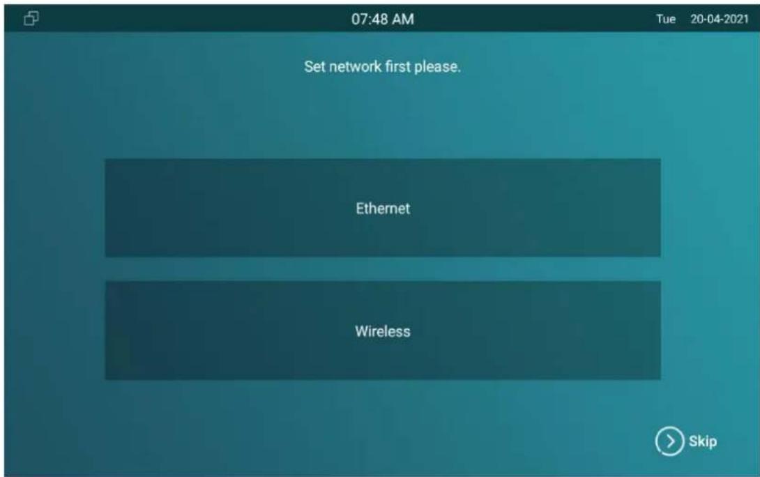

Note:
- Please refer to the chapter on Network Setting&Other connection for the configuration of the Ethernet and wireless network connection
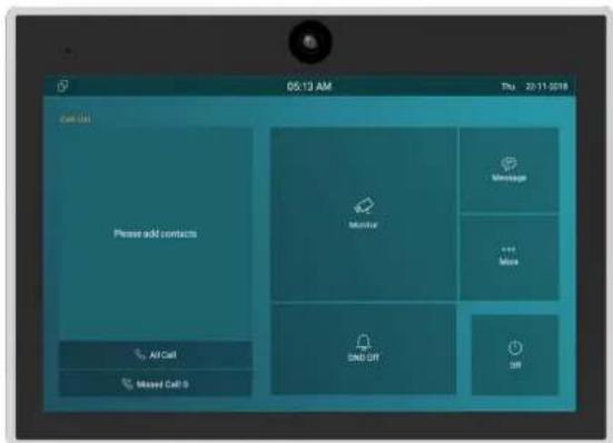
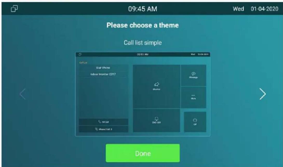
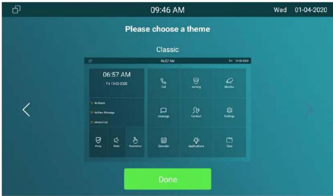
1.2. Device Home Screen Type Selection
Akuvox indoor monitor supports two different home screen display mode-Call list simple, Classic. Choose one suitable mode for your scenarios.
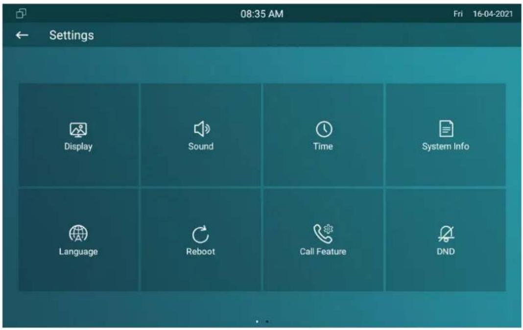
1.3. Accessing the Device Setting on the Device
1.3.1. Accessing Device Basic Setting.
You can access the device's basic setting and advance setting where you
can configure different types of functions as needed. To access the device basic setting by pressing More > Settings.
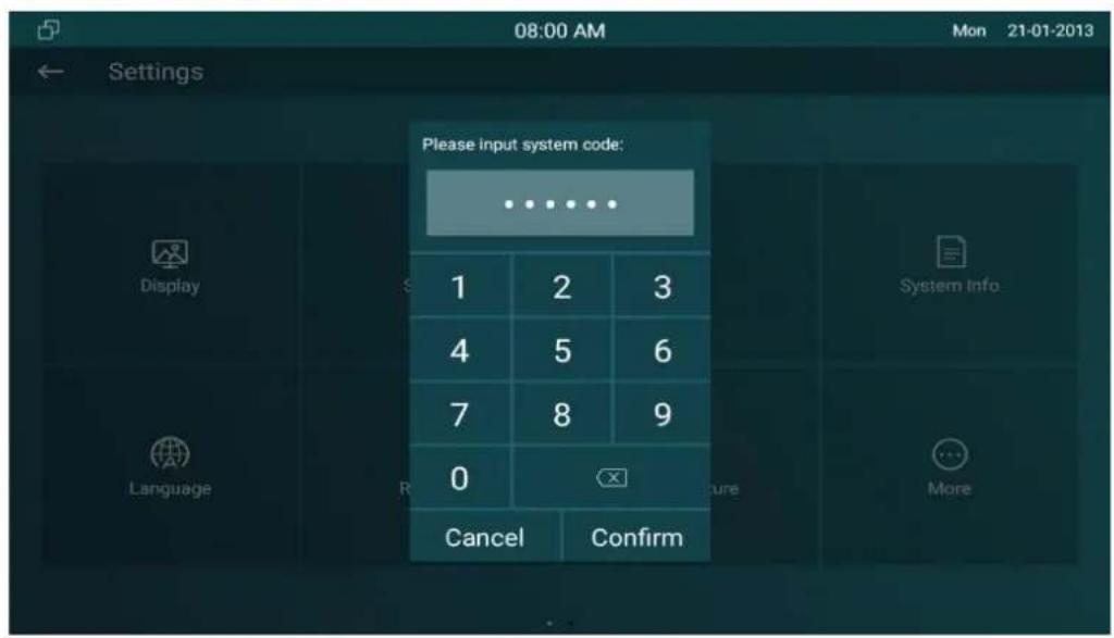
1.3.2. Accessing Device Advanced Setting
To access the advanced setting, press Setting then press Advanced Settings icon. Press password 123456 (by default) to enter the advanced setting.
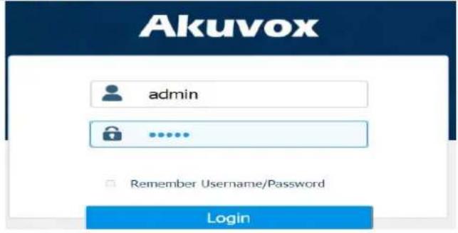
1.4. Access the Device Setting on the Web Interface
You can also enter the device IP address on the web browser in order to log in the device web interface by user name and password admin/admin where you can configure and adjust parameter etc.

Tip:
- You can also obtain the device IP address using the Akuvox IP scanner to log in the device web interface. Please refer to the U below for the IP scanner application: http://wiki.akuvox.com/doku.php?id=tool:ip_scanner&s[]=ip&s[]=scanner

Note:
- Google Chrome browser is strongly recommended.
- The Initial user name and password are "admin" and please be case-sensitive to the user names and passwords entered.
1.5. Language Setting
When you first set up the device, you might need to set the language to your need or you can do it later if needed. And the language can either be set up directly on the device or on the device web interface according to your preference.
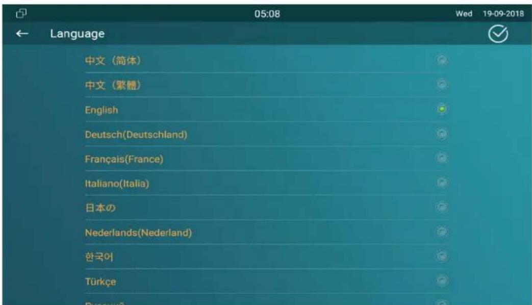
1.5.1. Language Setting on the Device
Language setting can be configured on the device and on the device web interface that allows you to select or change the language for screen display to your preference. To configure the language display on the device Setting > Language screen.
1.6. Time Setting
Time setting can be set up on the device and on the device web interface in terms of time zone, date and time format etc.
1.6.1.Time Setting on the Device
To set up time setting on the device Setting > Time screen.
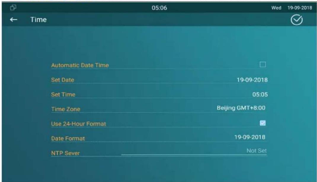
Parameter Set-up:
- Automatic Date: automatic Date is switched on by default, which allows the date& time to be automatically set up and synchronized with the default time zone and the NTP server (Network Time Protocol). You can also set it up manually by ticking the check box and then enter the time and date you want and press the Save tab to save the setting.
- Time Zone: select the specific time zone depending on where the device is used. The default time zone is GMT+0.00.
- Date Format: select the date format as you like among the three format options. The six formal options are Y-M-D, Y/M/D, D-M-Y, D/M/Y, M-D-Y, M/D/Y.
● Time Format: select 12 hour or 24 hour time format as you like.
● NTP Server: enter the NTP server you obtained in the NTP server field.
Note:
- When the Automatic Date&Time toggle switch is toggled of then parameters related to NTP server will become uneditable. And when the switch is toggled on, then time date will be denied editing.
1.6.2.Time Setting on the Device Web Interface
Time setting on the web Phone > Time interface also allows you to set up the NTP server address that you obtained to automatically synchronize your time and date. And when your time zone is selected, the device will automatically notify the NTP server of its time zone so that the NTP server can synchronize the time zone setting in your device.
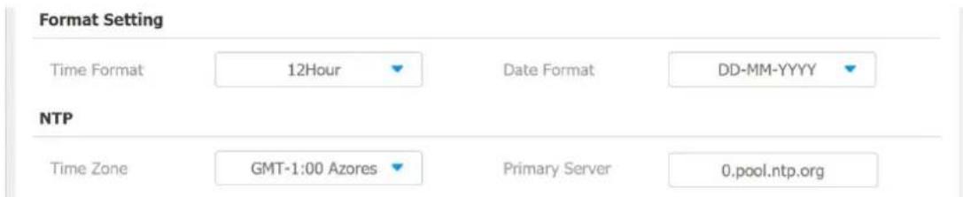
Parameter Set-up:
● NTP Server: enter the NTP server you obtained in the NTP server field.
Screen Display Configuration
IT83/IT82/C317/C315 series indoor monitor allow you to enjoy a variety of screen displays to enrich your visual and operational experience through the customized setting to your preference.
1.7. Screen Display setting on the Device
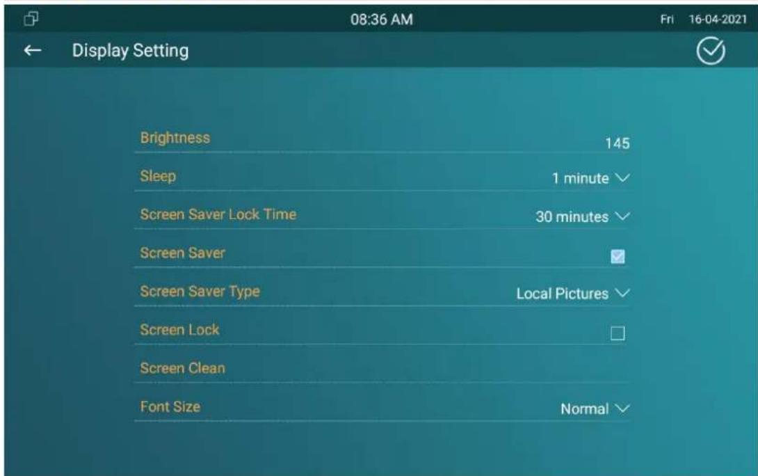
You can configure a variety of features of the screen display in terms of brightness, screen saver and font size, etc. You can do this configuration on device Setting > Display screen.
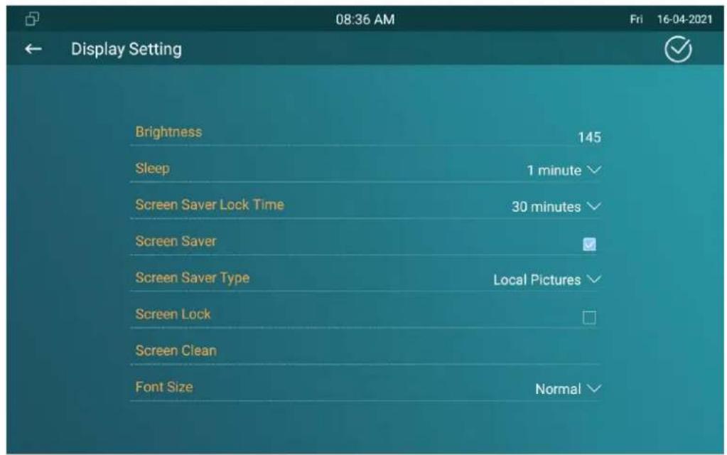
Parameter Set-up:
● Brightness: press on the brightness setting and move the yellow dots to
adjust the screen brightness. The default brightness is "145".
- Sleep: set the timing for the device screen to be turned off. You can select the timing among eight options: 30 seconds, 1 minute, 2 minutes, 5 minutes, 10 minutes, 30 minutes, 1 hour. For example, if you set it as 1 minute then the screen will be turned off if there is no operation on the device for 1 minute. However, if you turn on the function, then the device screen will not be turned off until screen saver display reaches its configured time duration.
- Screen Saver Lock Time: set the time duration for the screen saver among 4 options: 30 minutes, 1 hour, 2 hours, Never. for example if select Never then the screen saver will stay permanently on.
- Screen Saver: tick the square box to enable the screen saver function.
- Screen Saver Type: select screen saver type among seven options: SDMC Pictures, Local Pictures, SDMC+Local Pictures, SDMC Videos, Local Videos, SDMC+Local Videos, Clock. Details for the screen saver types are shown below:
| NO. | Screen Saver Type | Type Description |
| 1 | SDMC Pictures | Display pictures from SDMC as the screen saver. |
| 2 | Local Pictures | Display picture uploaded to the indoor monitor as t screen saver. |
| 3 | SDMC+Local Pictures | Display pictures from SDMC and the indoor monitor rotation as the screen saver. |
| 4 | SDMC Videos | Display videos from SDMC as the screen saver. |
| 5 | Local Videos | Display videos from the indoor monitor as the scre saver |
| 6 | SDMC+Local Videos | Display videos from SDMC and the door phone in rotation as the screen saver. |
| 7 | Clock | Display the clock as the screen saver. |
- Screen Lock: tick the screen lock if you want to lock the screen after the screen is turned off (turn dark). You are required to enter the system code to unlock the screen or you can unlock the screen by facial recognition.
- Screen Clean: press on Screen clean feature first before you start wiping the screen clean. And this helps you avoid unwanted changes in the settings incurred while you are wiping the screen.
- Font Size: select the font size among four options "Small", "Normal", "Large", "Huge" according to your need.
1.8. Screen Display Setting on the Web Interface
IT83/IT82/C317/C315 series indoor monitor allows you to enjoy a variety of screen displays to enrich your visual and operational experience through the customized setting to your preference.
1.9. Screensaver Configuration
1.9.1.Configure Screensaver on the Device
To configure screensaver on device Setting > Display screen.
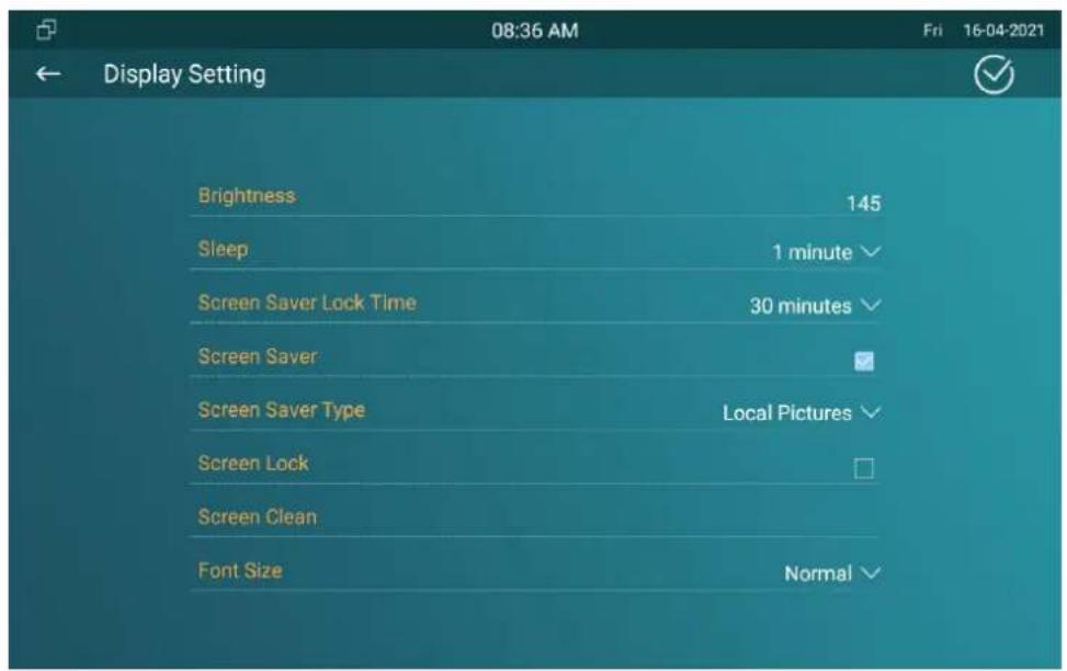
Parameter Set-up:
- Screen Saver Lock Time: set the time duration for the screensaver among 4 options: "30 minutes", "1 hour", "2 hours", "Never". for example if select "Never" then the screen saver will stay permanently on.
- Screen Saver: Slide the switch to enable the screensaver function.
- Screen Saver Type: select screen saver type among seven options: SDMC Pictures, Local Pictures, SDMC+Local Pictures, SDMC Videos, Local Videos, SDMC+Local Videos, Clock.
1.9.2. Upload ScreenSaver
You can upload screen saver pictures/videos separately to the device and to the device web interface for a public purpose or for a greater visual experience.
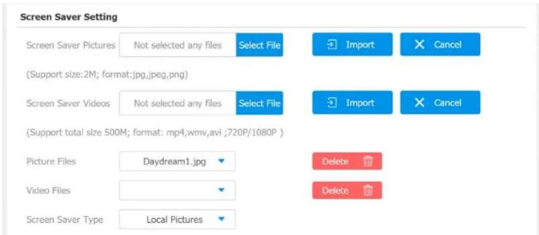

Note:
- The previous pictures with a specific ID order will be overwritten when repetitive designation of pictures to the same ID order occurred.
- The pictures uploaded should be in JPG format with 2M maximum.
1.10. Upload Wall Paper
You can customize your screen background picture on device web Phone > Display Setting > Wallpaper interface in order to achieve the visual effect and experience you need for your personalized screen background display.
Wallpaper
Wallpaper
Not selected any files
Select File

Import

Cancel
(Support size:2M; Formate:jpg,jpeg,png; Resolution: 1280x800)
1.11.Status Bar
Status bar setting is for you to customize the device status bar color according to your scenarios. You can do this configuration on web Phone > Display Setting > Status Bar interface. Choose Custom mode then adjust RGB value for the status bar.
Status Bar
Background Color
Custom

Custom Color
F27D18

natural_image
Color wheel with a gradient square at center, no text or symbols present1.12. Upload Device Booting Image
You can upload the booting image to be displayed during the device's booting process if needed on device web Phone > Logo interface.
Boot Logo
Boot Logo(.zip/.png)
Not selected any files
Select File

Import
Reset
(Format: max 1280*800 png)

Note:
● The pictures uploaded should be in .png or .zip format.
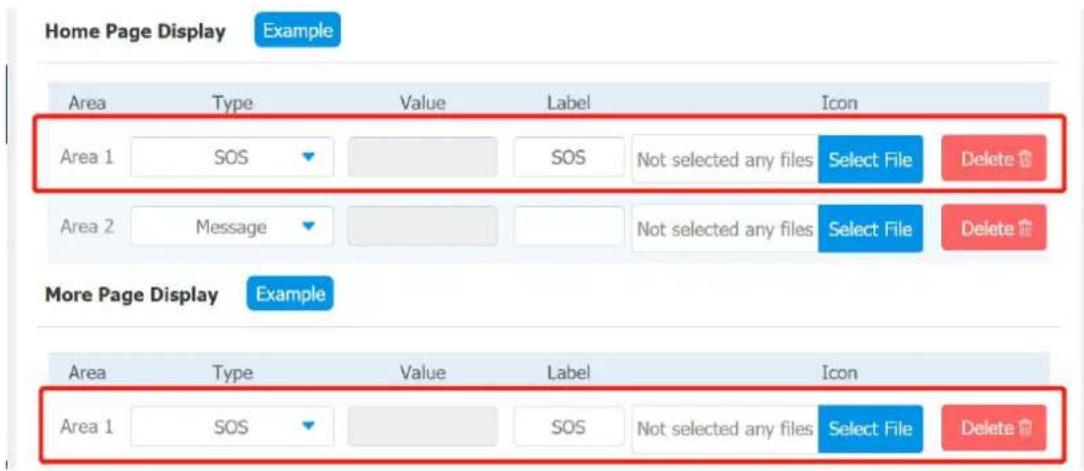
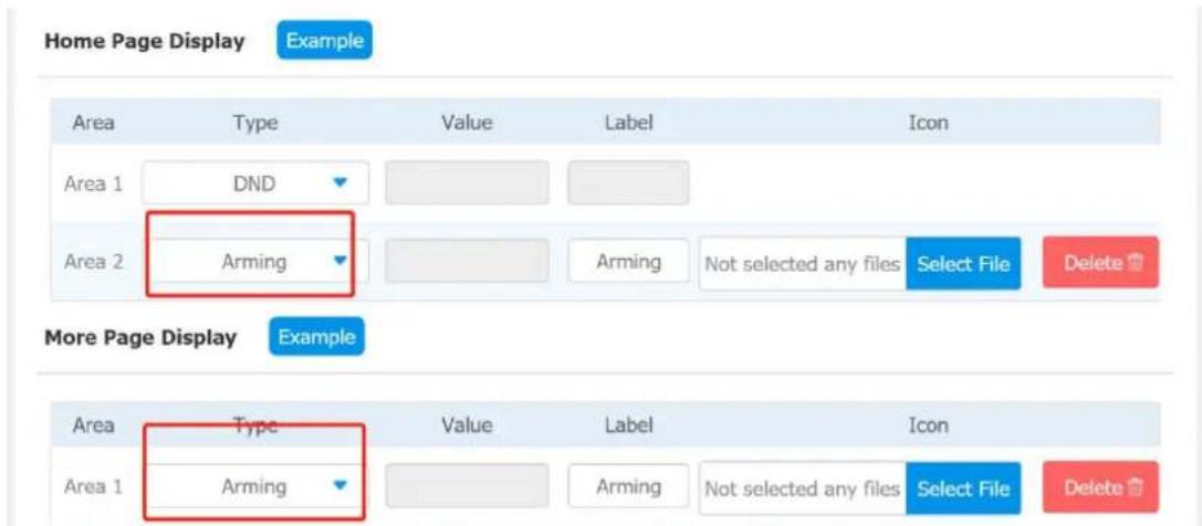
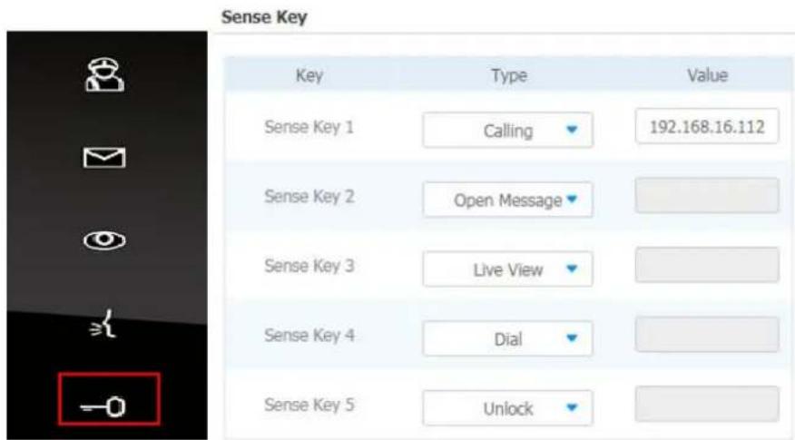
1.13. Icon Screen Display Configuration
IT83/IT82/C317/C315 series indoor monitor allow you to customize icon display on the home screen and More screen for the convenience of your operation on device web Phone > Key/Display interface. This article helps you to set up the icon display properly on the screens according to your preference.

Parameter Set-up:
- Type: click to select among sixteen icon options: "DND", "Message", "Contact", "Call", "Display", "System info", "Setting", "Sound", "Arming", "SOS", "Browser", "Motion Detection", "Custom APK", "Relays", "Unlock", "N/A" is selected, the icon display in the corresponding area will disappear.
- Value: enter the value if you select the icon type "Custom APK" and "Browser". For example, when you select "Custom APK", you are required to enter its package name and class name in the corresponding Value field before the APK icon can be displayed on the home screen. If "Browser" is selected, you are required to enter the URL of the browser before the browser icon can be displayed. while the value is not applicable to other icon types.
- Label: click to rename the icon if need, while DND icon can not be renamed.
- Icons: click to select the picture to be uploaded as the icon to be displayed.

Note:
- You can configure 4 icons in area 1,2,3, and 4 on the home screen

Note:
- You can configure 6 icons on the More screen.
Akuvox IT83/IT82/C317/C315 series indoor monitors provide you with various types of ringtone and volume configuration ranging from Mic volume, Ring volume, Talk volume, Tone volume and Media volume. You can configure them on the device directly or on the web interface.
1.14.Volume Configuration
1.14.1. Configure Volume on the Device
To set up the volumes on the device Setting > Sound screen.
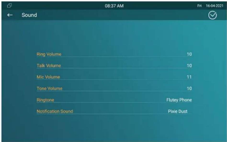
Parameter Set-up:
-
Ring Volume: adjust the incoming call ringtone volume.
● Talk Volume: adjust the speaker volume during the call.
● Mic Volume: adjust the volume of your voice to be heard.
● Tone Volume: adjust the dial tone volume. -
Ringtone: select ringtone for incoming calls.
● Notification Sound: select ringtone for the incoming messages.
1.14.1.1. Configure Volume on the Web Interface
You can configure the volumes and tones and customize your doorbell sound and alarm ringtone by uploading the audio file to your preference on device web Phone > Audio interface.
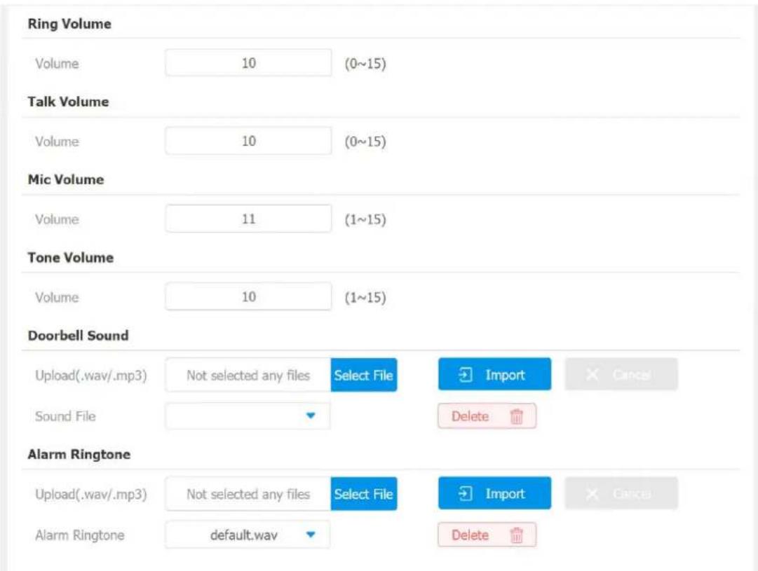

Note:
- Doorbell sound files and Alarm Ringtone files to be uploaded m be .WAV or MP3 format.
Phone Book Configuration
1.15.Phone Book Configuration on the Device
You can configure the contacts list in terms of adding and modifying contact groups or contacts on the device More > Contacts > Local PhoneBook directly.
1.15.1. Add Contacts
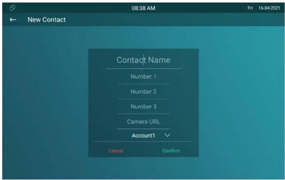
Parameter Set-up:
- Contact Name: enter the name and save.
● Number: enter the IP or SIP number to save. - CameraUrl: enter the RTSP URL for video preview.
- Account1: select which account to use to dial out, Account 1 or Account 2.

Note:
- The RTSP URL format is rtsp://device IP/live/ch00_0.
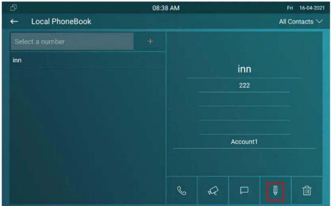
1.15.2. Edit Contacts
Select the exiting contact and click Edit to modify.
1.15.3. Blocklist Settings on the Device
you can choose from the contact list the contact you want to add to the block list
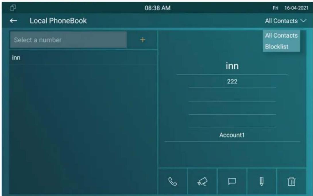

Note:
- You can delete contacts regardless of whether it is on the All Contacts screen or the Blocklist screen
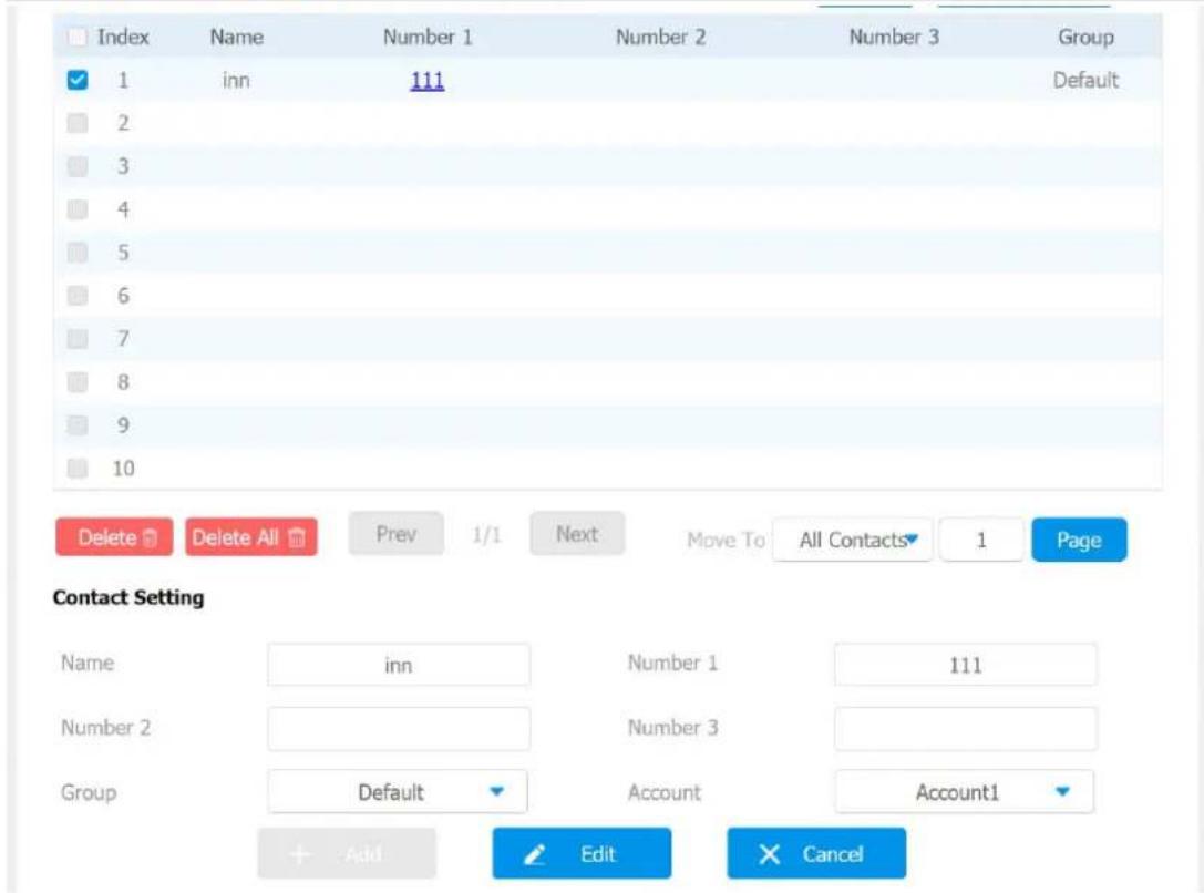
1.16.Phone Book Configuration on the Web Interface
1.16.1. Contact Configuration
To conduct contact configuration on web Contacts > Local Contacts interface. The existing contacts will show in the below list after their are being added.
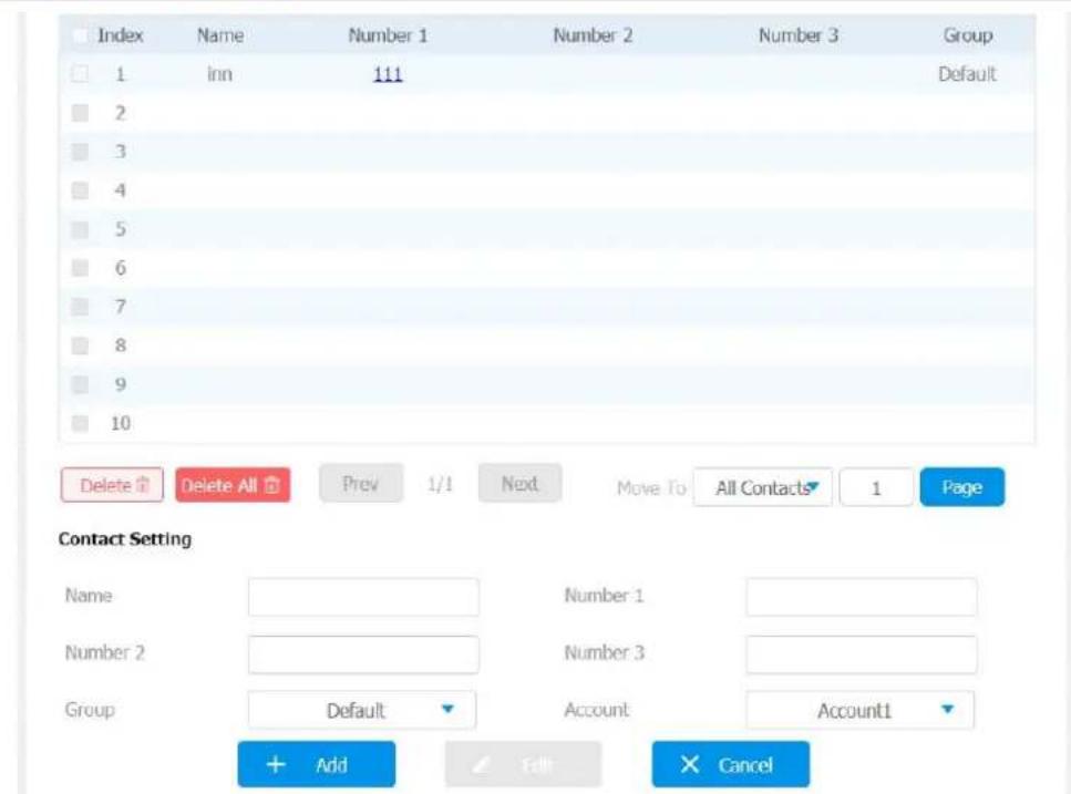
Parameter set-up:
- Name: enter the contact name to be saved.
● Number: enter the contact number (SIP or IP number) to be saved.
● Group: select Default or Blocklist group. - Account: select Account1 or Account2.
1.16.2. Contact Management
You can search, display, edit, and delete the contacts in your contacts list on web Contacts > Local Contacts interface.
You can dial out a number using the contact phone number on web Contacts > Local Contacts interface.

1.16.3. Block List Setting on the Web Interface
You can set the blocklist directly in the contact list on the web Contacts > Local Contacts > Contacts List Setting interface or set it when editing a contact.
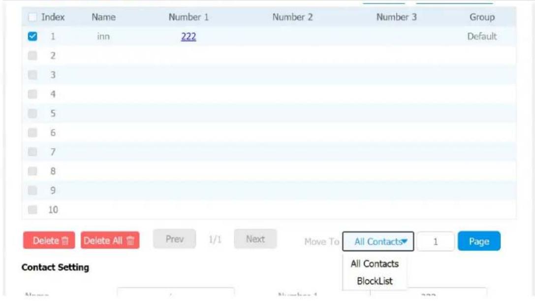

Note:
- If you want to remove the contact from the blocklist on the interface, you can change the group to the "Default" when e the contact.
1.16.4. Contact Display
You can configure the contact display order and control whether to display the discovery device on the device.

Parameters Set-up:
- Contacts Sort By: There are three modes Default, ASCII code and Created time mode for showing the contact list.
● Show Local Contacts Only: if enable the function, the contact on device
will only show local phonebook, the contact for discovery mode will be hidden.
1.16.5. Contacts Import and Export on the Web Interface
When the contact becomes so many that you can not afford to manage each contact one by one manually, you can import and export the contacts in batch on the device web Contacts > Local Contacts interface.
Import/Export
Contacts
Not selected any files
Select File
Import
Export
× Cancel
(.XML)
Import
Export
× Cancel
(.CSV)

Note:
- The contact file can only be imported or exportd in .xml or .csv format.
1.17.Device Network Configuration
You can check for the door phone's network connection info and configure the default DHCP mode (Dynamic Host Configuration Protocol) and static IP connection for the device either on the device or on the device web interface.
1.17.1. Configuring Network Connection on the Device
To check and configure the network connection on the device Advance Settings > Network screen.
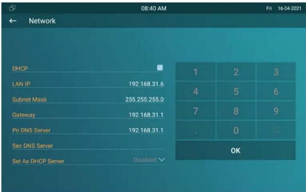
Parameter Set-up:
- DHCP: select the DHCP mode by moving the toggle switch to the right. DHCP mode is the default network connection. If the DHCP mode is turned on, then the door phone will be assigned by the DHCP server with IP address, subnet mask,default gateway,and DNS server address automatically.
- Static IP: select the static IP mode by ticking the DHCP check box. When static IP mode is selected, then the IP address, subnet mask, default gateway, and DNS servers address have to be manually configured according to your actual network environment.
- IP Address: set up the IP Address if the static IP mode is selected.
- Subnet Mask: set up the subnet Mask according to your actual network environment.
- Default Gateway: set up the correct gateway default gateway according to the IP address of the default gateway.
- LAN DNS 1/2: set up preferred or alternate DNS Server (Domain Name Server) according to your actual network environment. Preferred DNS server is the primary DNS server address while the alternate DNS server is the secondary server address and the door phone will connects to the alternate server when the primary DNS server is unavailable.

Note:
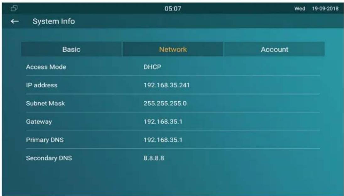
- You can press System Info icon and then press Network tab on the Settings screen to check the device network status.
● The default system code is "123456".
1.17.2. Configuring Device Network Connection on the Web Interface
To check the network on the web Status > Network information interface.
Network Information
| LAN Port Type | DHCP Auto | LAN Link Status | Connected |
| LAN IP Address | 192.168.31.6 | LAN Subnet Mask | 255.255.255.0 |
| LAN Gateway | 192.168.31.1 | LAN DNS1 | 192.168.31.1 |
| LAN DNS2 |
To check and configure network connection on the device web Network > Basic interface.
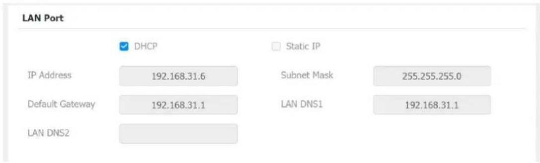
Parameter Set-up:
- DHCP: select the DHCP mode by checking the DHCP box. DHCP mode is the default network connection. If the DHCP mode is selected, then the indoor monitor will be assigned by the DHCP server with IP address, subnet mask, default gateway, and DNS servers address automatically.
- Static IP: select the Static IP mode by checking off the DHCP square box. When static IP mode is selected, then the IP address, subnet mask, default gateway, and DNS servers address have to be manually configured according to your actual network environment.
- IP Address: set up the IP address if the static IP mode is selected.
- Subnet Mask: set up the subnet mask according to your actual network environment.
- Default Gateway: set up the correct gateway default gateway according to the IP address of the default gateway.
● LAN DNS1/2 Server: set up DNS (Domain Name Server) according to your actual network environment. Preferred DNS Server is the primary DNS server address while the Alternate DNS Server is the secondary server address and the door phone connects to the alternate DNS server when the preferred DNS server is unavailable.
1.18.Device Deployment in Network
Akuvox IT83/IT82/C317/C315 series indoor monitors should be deployed before they can be properly configured in the network environment in terms of their location, operation mode, address and extension numbers as opposed to other devices for device control and the convenience of the management. To deploy the device in the network on web Network > Advanced > Connect Setting interface.
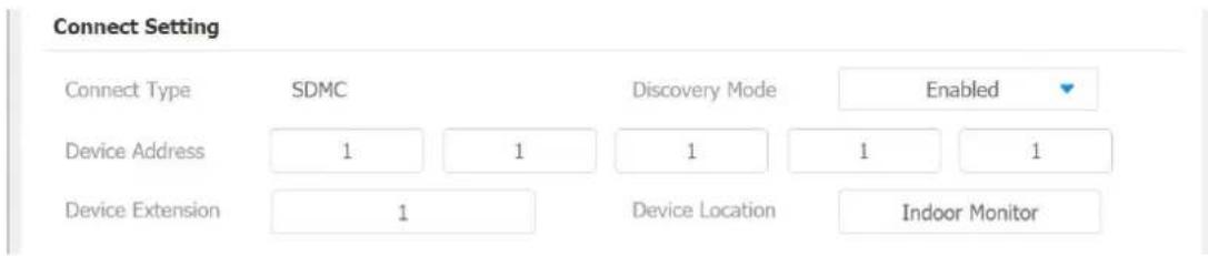
Parameter Set-up:
- Connect Mode: It is automatically set up according to the actual device connection with a specific server in the network such as SDMC or Cloud and None. None is the default factory setting indicating the device is not in any server type, therefore you are allowed to choose Cloud, SDMC in discovery mode.
● Discovery Mode: to turn on the discovery mode of the device so that it can be discovered by other devices in the network, and disable if you want to conceal the device so as not to be discovered by other devices.
● Device Node: specify the device address by entering device location info from the left to the right: Community, Unit, Stair, Floor, Room in sequence.
● Device extension: enter the device extension number for the device you installed.
● Device Location: enter the location in which the device is installed and used.
1.19. Device NAT Setting
NAT (Network Address Translation) allows hosts in an organization's private intranet to transparently connect to hosts in the public domain.
There is no need for internal hosts to have registered Internet addresses. It is a way to translate the internal private network IP address into a legal network IP address technology. To set up NAT, you can do it on web Account > Advanced > NAT interface.
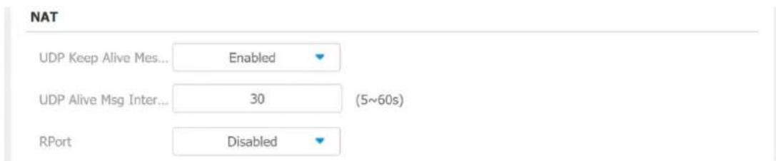
Parameter Set-up:
- UDP Keep Alive Messages: if enable NAT, the device will send out the message to the SIP server so that SIP server will recognize if the device is in online status.
- UDP Alive Msg Interval: set the message sending time interval from 5-60 seconds, the default is 30 seconds.
- RPort: check the RPort when the SIP server is in WAN (Wide Area Network).
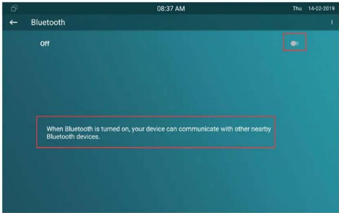
1.20. Device Bluetooth Setting
1.20.1. Device Bluetooth Pairing
After IT83/IT82/C317 series indoor monitors turn on the Bluetooth on the device Setting > Bluetooth screen, it can be paired with other device via Bluetooth.
1.20.2. Device Bluetooth Data Transmission
To transfer data via bluetooth by pressing Pair new device.
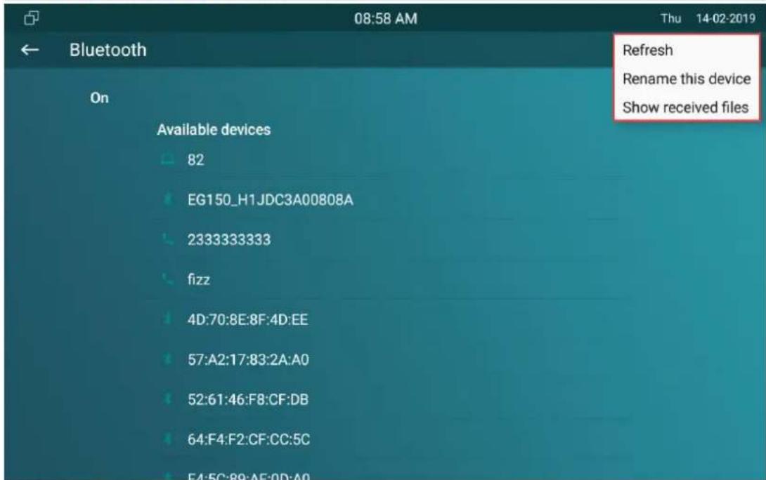
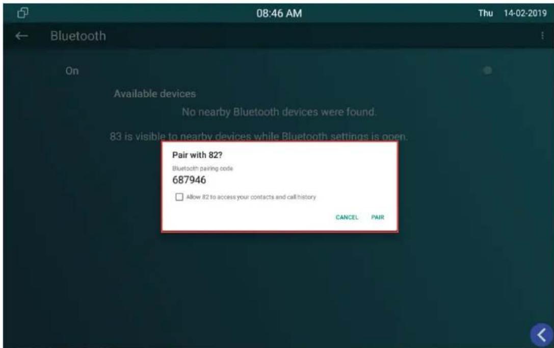
Note:
- After successful Bluetooth pairing, data transmission can be carried out.
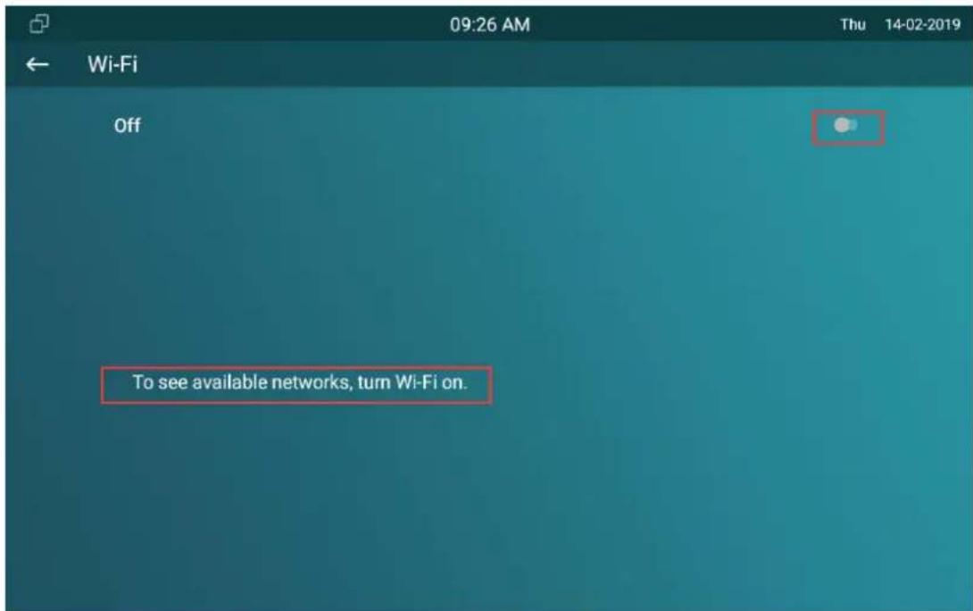
1.21.Device Wi-Fi Setting
In addition to wired connection, the device also supports Wi-Fi connection. You can set the Wi-Fi on device Advance Settings > WLAN screen.
Intercom Call Configuration
1.22.IP call & IP Call Configuration
IP calls and SIP calls can be made directly on the intercom device by entering the IP number on the device. And you can also disable the direct IP call if you allow no IP call to be made on the device. To configure the IP call feature and port on the device web Phone > Call Feature > Others interface.
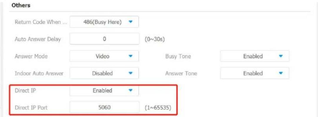
Parameter Set-up:
- Direct IP Call: tick the check box to enable the direct IP call. For example, if you do not allow direct IP call to be made on the device, you can untick the check box to terminate the function.
- Direct IP Call Port: the direct IP Call Port is "5060" by default with the port range from 1-65535. And you enter any values within the range other than the 5060, you are required to check if the value entered is consistent with the corresponding value on the device you wish to establish a data transmission with.
1.23.SIP Call &SIP Call Configuration
You can make SIP call (Session Initiation Protocol) in the same way as you
do for making the IP calls on the device. However, SIP call parameters related to its account, server, and transport type need to configured first before you can make calls on the device.
1.24.SIP Account Registration
Akuvox IT83/IT82/C317/C315 series indoor monitors support two SIP accounts that can all be registered according to your applications. For example, you can switch between the two SIP accounts. The SIP account can be configured on the device and on the device interface. To configure the SIP account on the device Advance Settings > Account screen.
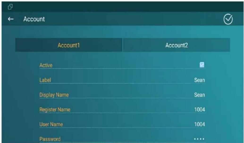
The parameter settings for SIP account registration can be configured on the Account setting screen and they can also be configured on the device web interface. To perform the SIP account setting on the Web Account > Basic > SIP Account Interface.
SIP Account
Status
Disabled
Account
Account 1
Account Active
Disabled
Display Label
Display Name
Register Name
User Name
Password
●●●●●●●
Parameter Set-up:
- Status: check to see if the SIP account is registered or not.
- Account: select Account1 or Account2.
- Account Enabled: check to active the registered SIP account.
- Display Label: configure the device label to be shown on the device screen.
- Display Name: configure the name, for example, the device's name to be shown on the device being called to.
- Register Name: enter the SIP account register Name obtained from the SIP account administrator.
- Username: enter the user name obtained from SIP account administrator.
- Password: enter the password obtained from the SIP server.
1.25.SIP Server Configuration
SIP server can be set up for device in order to achieve call session through SIP server between intercom devices. To perform the SIP account setting on the Web Account > Basic > SIP Account Interface.
SIP Server 1
Server IP
Port
5060
Registration Period
1800
(30\~65535s)
Parameter Set-up:
- Server IP: enter the Server's IP address number or its URL.
- Port: set up SIP server port for data transmission.
- Registration Period: set up SIP account registration time pan. SIP re-registration will start automatically if the account registration fails during the registration time span. The default registration period is "1800", ranging from 30-65535s.
1.26. Outbound Proxy Server configuration
An outbound proxy server is used to receive all initiating request messages and route them to the designated SIP server in order to establish call session via port-based data transmission. To configure outbound Proxy server on Account > Basic > Outbound Proxy Server interface.
Outbound Proxy Server
Enable Outbound
Disabled

Port
5060
Server IP
Backup Server IP

Port
5060
Parameter Set-up:
- Outbound Enable: enable or disable to turn on or turn off the outbound proxy server.
- Preferred Outbound Proxy Server: enter the SIP address of the outbound proxy server.
- Preferred Outbound Proxy Port: Enter the Port number for establish call session via the outbound proxy server.
- Alternate Outbound Proxy Server: set up Backup Server IP for the backup outbound proxy server.
- Alternate Outbound Proxy Port: enter the Port number for establish call session via the backup outbound proxy server.
1.27.SIP Call DND & Return Code Configuration
DND (Do not disturb) setting allows you not to be disturbed by any unwanted incoming SIP calls. You can set up DND related parameters properly on the device web Phone > Call Feature > DND interface to block SIP calls you do not intend to answer. In the mean time, you can also define the code to be sent to the SIP server when you want to reject the call.
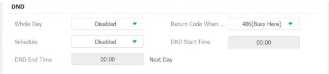
Parameter Set-up:
● DND: check Whole Day or Schedule to enable the DND function. DND function is disabled by default.
- Return Code When DND: select what code should be sent to the calling device via SIP server. 404 for "Not found"; 480 for "Temporary unavailable"; 486 for "busy here".
- Schedule : enable DND schedule for your indoor monitor. To configure a specific time to enable DND feature. If you choose Schedule for DND, the Whole Day tab is available.
● DND Start Time: the start time for DND schedule.
● DND End Time: the end time for DND schedule.
1.28.Device Local RTP configuration
For the device network data transmission purpose, device needs to be set up with a range of RTP port (Real-time Transport Protocol) for establishing an exclusive range of data transmission in the network. To set up device local RTP on web Network > Advanced > Local RTP interface.
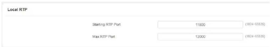
Parameter Set-up:
● Starting RTP Port: enter the Port value in order to establish the start point for the exclusive data transmission range.
● Max RTP port: enter the Port value in order to establish the end point for the exclusive data transmission range.
1.29.Data Transmission Type Configuration
SIP message can be transmitted in three data transmission protocols: UDP (User Datagram Protocol), TCP(Transmission Control Protocol), TLS (Transport Layer Security) and DNS-SRV. In the meantime, you can also identify the server from which the data come from. To do this configuration on web Account > Basic > Transport Type interface.

Parameter Set-up:
- UDP:select "UDP" for unreliable but very efficient transport layer protocol. UDP is the default transport protocol.
- TCP. select "TCP" for Reliable but less-efficient transport layer protocol.
- TLS: select "TLS" for Secured and Reliable transport layer protocol.
- DNS-SRV: select "DNS-SRV" to obtain DNS record for specifying the location of services. And SRV not only records the server address but also the server port. Moreover, SRV can also be used to configure the priority and the weight of the server address.
1.30.Call Setting
IT83/IT82/C317/C315 will auto answer all incoming calls if call auto-answer is enabled and receive live stream if live stream is enabled.
1.30.1. Call Auto-answer Configuration
IT83/IT82/C317/C315 will auto answer all incoming calls if call auto-answer is enabled and receive live stream if live stream is enabled. To enable or disable on web Account > Advanced > Call > Auto Answer interface. And set up the corresponding auto answer parameters on web Phone > Call Feature > Others interface.
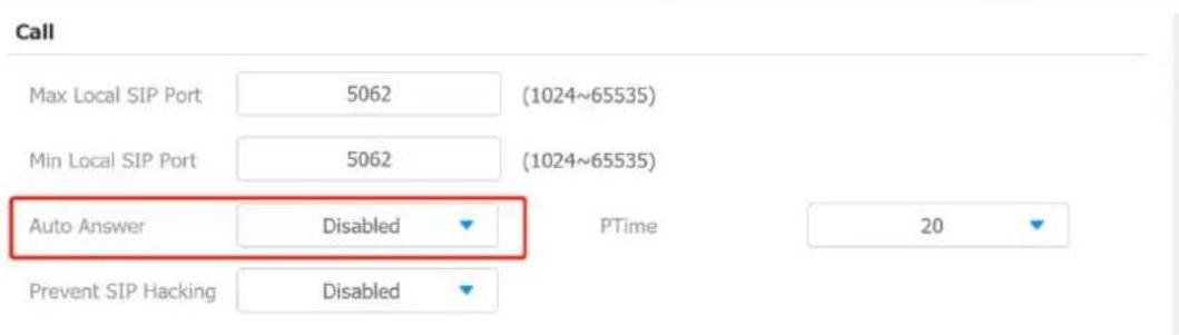
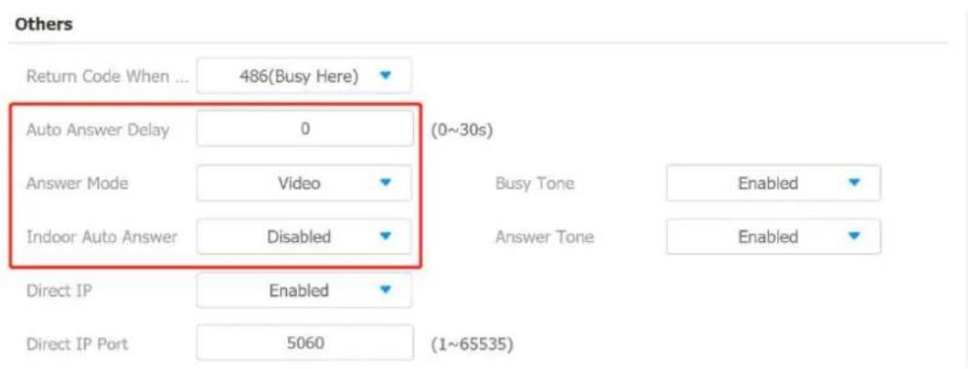
Parameter Set-up:
● Auto Answer: turn on the the Auto Answer function by ticking the square box.
● Auto Answer Delay: set up the delay time (from 0-30 sec.) before the call can be answered automatically. For example, if you set the delay time as 1 second, then the call will be answered in 1 second automatically.
- Answer Mode: set up the video or audio mode you preferred for answering the call automatically.
- Indoor Auto Answer Mode: turn on the the Auto Answer function for call from other indoor monitors by ticking the check box.
1.30.2. Auto-answer Allow List setting
Auto answered can only be applicable to the SIP or IP numbers that are already added in the auto-answer allow list of your indoor monitor. Therefore,
you are required to configure or edit the numbers in the white-list on web Phone > Call Feature > Auto Answer AllowList interface.
Auto Answer AllowList
SIP/IP numbers can be imported to or exported out of the indoor monitor in batch on web Phone > Call Feature > Allowlist Import/Export interface.
Allowlist Import/Export


Note:
- SIP/IP number files to be imported or exported must be in either .xml or .csv format.
- SIP/IP number must be set up in the phone book of the indoc monitor before they can be valid for the auto-answer function
1.30.3. Live Stream Setting
Receive Live Stream on the indoor monitor allows you to see the the video image (one way video stream) from the calling device such as a door phone whether or not you answered the call in audio or video mode, while the video image from your indoor monitor will not be sent to the calling devices in order to protect your privacy. To do the configuration on web Phone > Call Feature >Audio Call Settings interface.

When the feature is enabled, once a caller require a video call:
- Receive the incoming calls in video call mode so that both side can see each while talking in the two-way video conversation.
- Receive the incoming calls in audio call so that you can see the caller in the one-way video conversation while the call can not see you.

Note:
- Only device with camera module will have this feature.
1.31. Intercom Call Configuration
If you want to see the image at the door station before answering the incoming call, you can enable the intercom preview function on web Phone > Call Feature > Intercom interface.
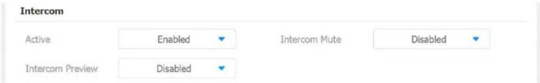
Parameter Set-up:
- Intercom Active: tick the check box to enabled or disabled intercom function.
- Intercom Mute: tick the check box to enable mute the voice from the callee side and vice versa.
- Intercom Preview: tick the check box to enable the incoming call preview function.
1.32.PTime Configuration
Ptime gives the length of time in milliseconds represented by the media in a packet. The SDP in the INVITE request sent by the calling party carries the ptime attribute, which indicates that the packing duration of the calling party's media is the value carried by ptime. After receiving the request message, the server replies with the ptime attribute in the SDP in 200 OK, indicating that the server-side support for the packaging time of the media is the value carried by ptime. The caller negotiates according to the ptime attribute carried in the SDP in the 200 OK, and finally sends the media package time, that is, the ptime value.
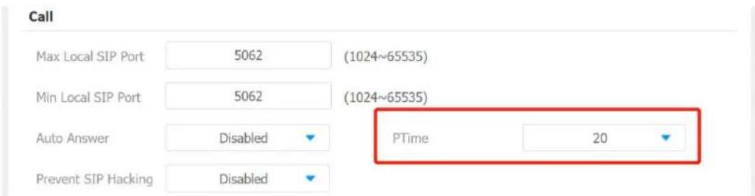
Parameter Set-up:
- PTime: you can disable the PTime feature. Or set up it from 10 to 60 seconds.
1.33.SIP Hacking Protection
Internet phone eavesdropping is a kind of network attack, which aims to eavesdrop on the communication sessions of others in an unauthorized way. Attackers can use this malicious activity to capture and read content containing sensitive and confidential information. SIP hacking prevents SIP call from hacking in the Internet.
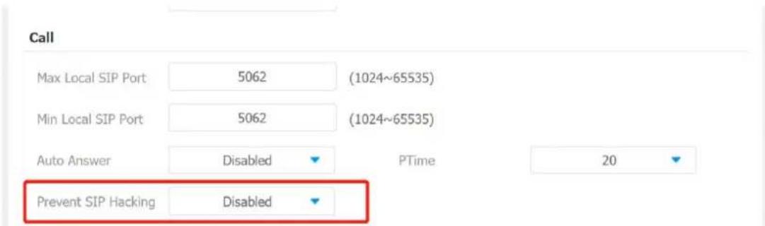
Parameters Set-up:
● Prevent SIP Hacking: enable to active this feature during using sip call. This feature is only available for SIP call, not IP call.
1.34. Emergency Call Setting
Emergency call is used to call out three emergency contacts when you are in urgent status. Especially for the elders and children. Press SOS key, the phone will automatically initiate the target SOS numbers.
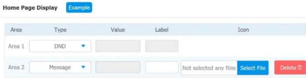
1.34.1. SOS Number Display
To display SOS softkey on web Phone > Key/Display > Home Page Display interface. The icon will show in the main interface or more interface after configured.
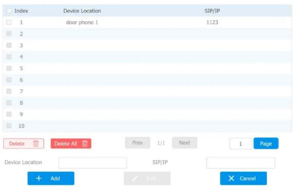
1.34.2. SOS Number Settings
To set up SOS numbers on device web Phone > Intercom.
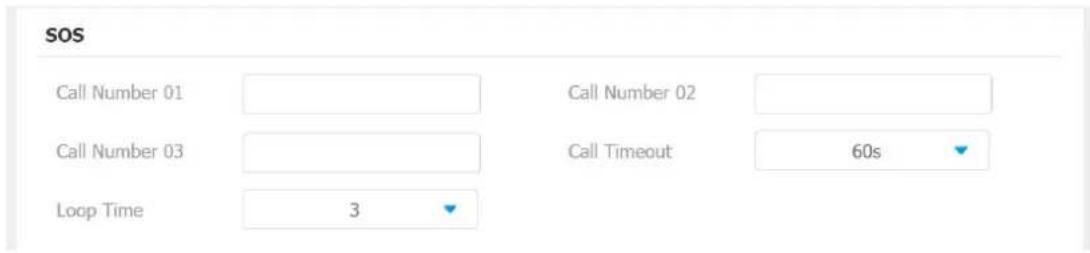
Parameter Set-up:
- Call Number: to set up 3 SOS numbers. Once users press SOS key on the home screen (SOS display key shall be set on the web manually), indoor monitors will call out the number in order.
- Call Timeout: set up the timeout for each number. Once users call out, if the other side will not answer within the timeout, indoor monitors will continue to call the next number.
- Loop Times: to setup the call loop times.
1.35.RF Setting (Optional)
IT83A/IT82A/C317A/C315A supports RF(Radio Frequency) module to connect a pendent to trigger some actions, like unlocking or making a emergency call. After pairing pendents and indoor monitors, then setup different RF actions on device Advance Settings > RF Settings. After power on the pendent, click Learning and press pendent one time, they will be paired. The green indicator means pairing successfully.
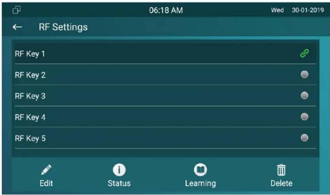
Parameters Set-up:
- Short Press When Idle: if you choose Assistance Call for short pressing which means when you pressing the pendent about 1s, the indoor monitor will make the pre-configured emergency call. No Action is default.
- Long Press: if you choose Unlock1/2/3 for long pressing which means when you pressing the pendent about 3s, it will send out a unlocking signal to the door phone during a call.
1.36.Multicast Configuration
IT83/IT82/C317/C315 allows you to conduct one-to-many broadcasting via multicast function on web Phone > Multicast interface.
Multicast Setting
Multicast Group
Disabled
Multicast List
Multicast Group
Multicast Address
Multicast Group
Multicast Group
Multicast Group
Listen List
Listen Group
Listening Address
Label
Listen Group
Listen Group
Listen Group
Parameter Set-up:
- Multicast Setting: to set the indoor monitor in one of the groups or disable this function.
- Multicast List: to fill in the parameters of multicast group. Indoor monitor will establish multicast calls to other indoor monitors which are set in multicast group.
- Listen List: to fill in the parameters of listen group. Indoor monitor will receive multicast calls if some indoor monitors call the listen group.
- Label: To show the label name on the calling interface if users establish all call.
1.37.Call Forwarding Setting
Call Forward is a feature used to redirect an incoming call to the specific third party. Users can redirect the incoming call based on different scenarios. Typically, call forward has three modes: Always Forward/ No Answer Forward/Busy Forward.
1.37.1. Call Forwarding Configuration on the Device
To do the configuration on the Device Settings > Call Feature interface.
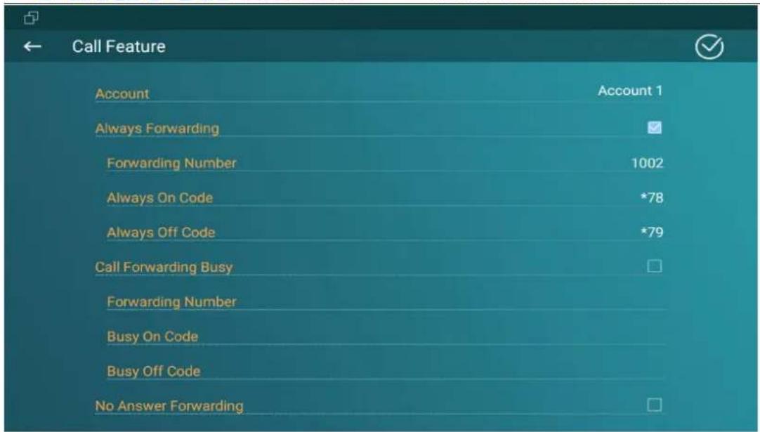
Parameter Set-up:
- Account: to choose which account to implement call forwarding feature.
● Always Forwarding: to enable always forwarding function; all incoming calls will be automatically forwarded to a specific number.
- Busy Forwarding: To enable busy forwarding function; incoming calls will be forwarded to a specific number if phone is busy.
- No Answer Forwarding: To enable no answer forwarding function; incoming calls will be forwarded to a specific number if phone is not picked within no answer ring time.
- Target Number: To enter the specific forward number if X933 enables Always Forwarding / Busy Forwarding / No Answer Forwarding.
1.37.2. Call Forwarding Configuration on the Web Interface
To set up forward function on web Phone > Call Feature > Forward Transfer interface.
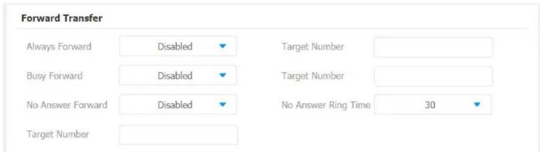
Parameter Set-up:
● Always Transfer: To enable always forwarding function; all incoming calls will be automatically forward to a specific number.
- Busy Transfer: To enable busy forwarding function; incoming calls will be forwarded to a specific number if phone is busy. No Answer Transfer: To enable no answer forwarding function; incoming calls will be forwarded to a specific number if phone is not picked within no answer ring time.
- Designated Call Forward Number To enter the specific forwarding number if X933 enables always forwarding / call forwarding busy / no answer forwarding.
- No Answer Call Transfer Duration (Sec): to set the no answer time interval from 0-120 seconds before the call is transferred to a designated number.
Intercom Message Setting
You can read, create, and delete messages on the Message screen.
1.38.Manage Messages
You can check, create and clear messages as needed on the indoor monitor Messages screen. Click New to create a new text message and Delete icon to delete the existed messages.
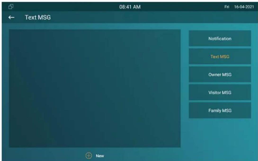
Parameter Set-up:
- New: press this icon to create a new message
- Delete: press this icon to clear the messages that have been selected.
- Cancel: press this icon to cancel the action you do.
1.39. Configure Voice Message (MWI)
MWI (Message Waiting Indicator) is a notification that notifies you when you have a new voice mail message. To do the configuration on web Account >Advanced >Subscribe interface.

Parameter Set-up:
- MWI Subscribe: tick the check box to enable MWI function.
- MWI Subscribe Period : set up interval between the MWI Subscribe messages.
● Voice Mail Number: enter the voice mail number for accessing your voice mail messages.
Audio& Video Codec Configuration for SIP Calls
1.40.Audio Codec Configuration
Akuvox indoor monitor supports seven types of Codec (iLBC_13_3, iLBC_15_2, L16, PCMU, PCMA, G729, G722) for encoding and decoding the audio data during the call session. Each type of Codec varies in terms of sound quality. You can select the specific codec with different bandwidth and sample rate flexibly according to the actual network environment. To do the configuration on web Account> Advanced > Audio Codecs interface.
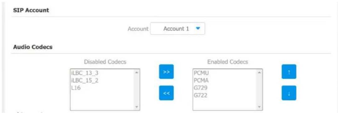
Please refers to the bandwidth consumption and sample rate for the four codecs types below:
| Codec Type | Bandwidth Consumption | Sample Rate |
| PCMA | 64 kbit/s | 8kHz |
| PCMU | 64 kbit/s | 8kHz |
| G729 | 8 kbit/s | 8kHz |
| G722 | 64 kbit/s | 16kHz |
| iLBC_13_3 | 8,16 kbit/s | 13.3kHz |
| iLBC_15_2 | 8,16 kbit/s | 15.2kHz |
| L16 | 128 kbit/s | variable |
1.41.Video Codec Configuration
IT83/IT82/C317/C315 series supports VP8, H263, H264, H265 codec that provides a better video quality at a much lower bit rate with different video quality and payload. To do the configuration on web Account > Advanced > Video Codecs interface. Choose an available video codecs and setup the codecs parameters.
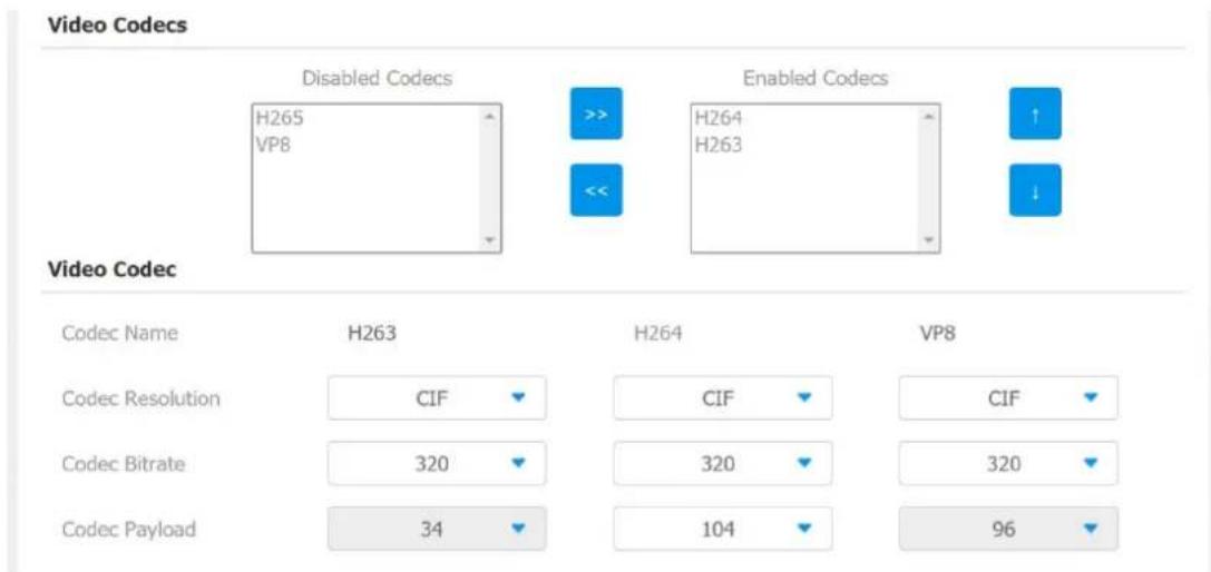
Parameter Set-up:
- Name: check to select the H264 video codec format for the door phone video stream. H264 is the video codec by default.
- Resolution: select the code resolution for the video quality among four options:"QCIF", "CIF", "VGA", "4CIF" and "720P" according to your actual network environment. The default code resolution is 4CIF.
- Bitrate: select the video stream bit rate (Ranging from 320-2048). The greater the bitrate, the data transmitted in every second is greater in amount therefore the video will be clearer. While the default code bitrate is 2048.
- Payload: select the payload type (ranging from 90-118) to configure audio/video configuration file. The default payload is 104.
Security
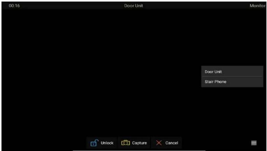
1.42. Monitor and Image
1.42.1. Monitor Setting
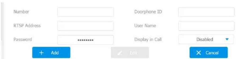
You can configure the monitor setting on the web Phone > Monitor interface. Enter IP/SIP number of door phone in Device number and fill in device name. Then set up the RTSP address. The RTSP format of the Akuvox door phone is rtsp://deviceIP/live/ch00_0. you can enable or disable display in the call. If enabled, when there is an incoming call from the monitor, the video will be displayed.
Door Phone
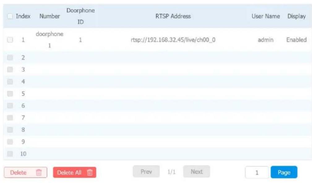
You can also import or export the monitor list in batch in the same interface. Import file can only support .xml format.
Monitor Import/Export

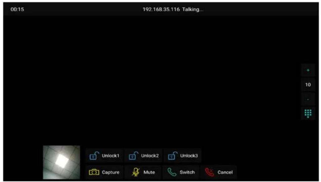
1.42.2. Video Image Capturing
To capture video image by pressing Capture during monitor or a video call.
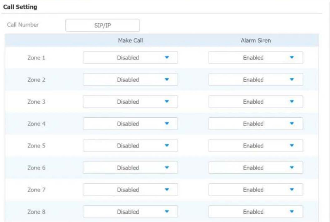
1.43. Alarm and Arming Configuration
Alarm feature is used to connect some alarm detection devices to protect your home safety. Akuvox indoor monitors support 8 alarm connectors which means you can connect 8 different alarm sensors in different rooms of your house. For example, connecting a smoker sensor in your kitchen to detect if the gas is leaking, the indoor monitor will ring and send the alarm message
to the target, like community property. Before checking Alarm feature on the device screen, you need to setup the Arming icon on the home page or more page on device web Phone > Key/Display interface.
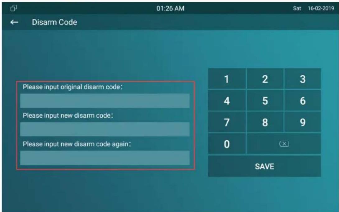
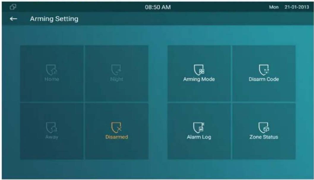
1.43.1. Configure Alarm and Arming on the Device
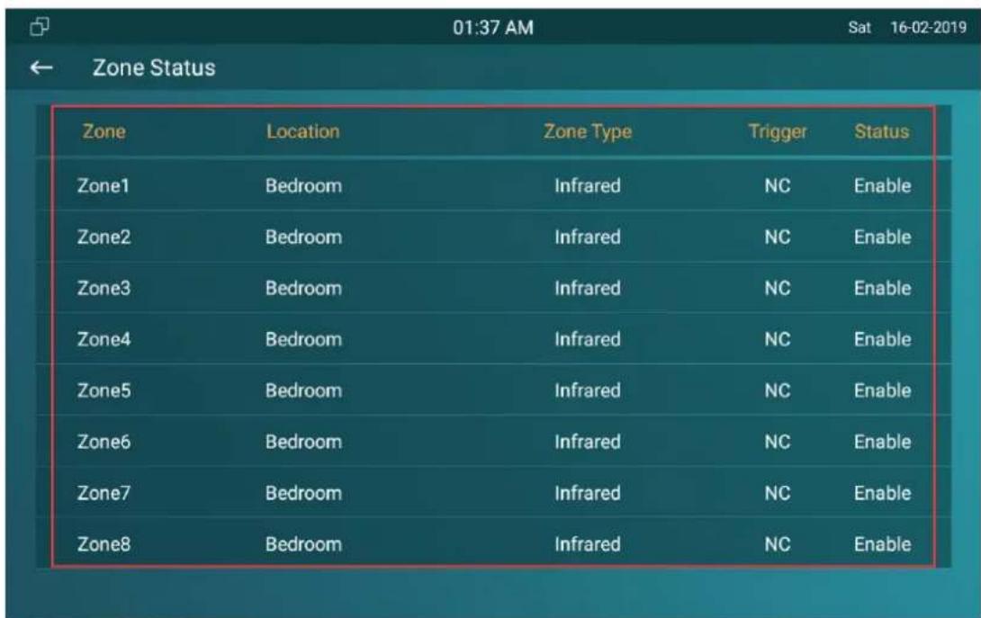
To configure the arming and disarm code on device Advance Settings > Arming/Disarm Code screen. Change the current password and save it.
To check the zone status on Arming > Zone Status screen.
1.43.2. Configure Alarm and Arming on the Web Interface
To set up a location-based alarm sensor on the device web Arming> Zone Setting > Zone Setting interface.
Zone Setting
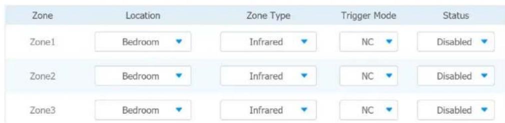
Parameter Set-up:
- Location: set up the location according to where the alarm sensor is stalled. You can select among ten location types: "Bedroom", "Gate", "Door" "Guest room", "Hall", "Window", "Balcony", "Kitchen", "Study" and "Bathroom".
- Zone Type: set up the alarm sensor types. You can select among four sensor types: "Infrared", "Drmagnet", "Smoke", "Gas", "Urgency".
- Trigger Mode: set sensor trigger mode between "NC" and "NO" according to your need.
- Status: set the alarm sensor status among three options: "Enable", "Disable","24H". Select "Enable" if you want to enable to the alarm, however you are required to set the alarm again after an alarm is disarmed. Select "Disable" if you want to disable the alarm, and select "24H" if you want alarm sensor to stay enabled for 24 hours without needing to set up the alarm manually again after the alarm is disarmed.
1.43.3. Configure Location-based Alarm
Configure the alarm sensor in the same way you do on the web interface.
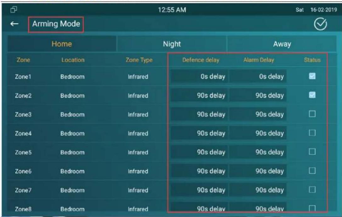
Parameters set up:
- Location: to select which location the detection device is located, including Bedroom, Guest room, Hall, Window, Balcony, Kitchen, Study and Bathroom.
- Zone type: to select the type of detection device, including Infrared, Drmagnet, Smoke, Gas, and Urgency.
- Defence delay: it means when users enable the arming mode, there will be 90 seconds delay time for the alarm mode to be activated.
- Alarm delay: it means when the sensor triggered, there will be 90 seconds delay time to announce the notification.
- Status: To enable or disable Arming mode on the corresponding Zone.
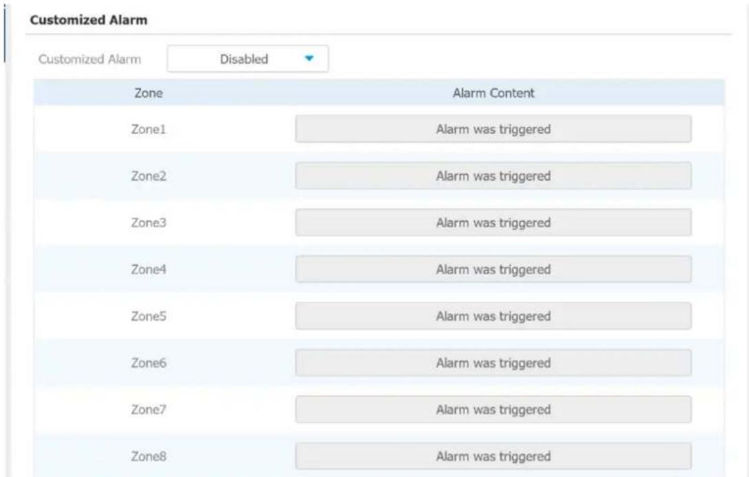
1.43.4. Configure Alarm Text
After the alarm sensor is set up, you are allowed to customize your alarm text shown on the screen when an alarm is triggered on web Arming> Zone Setting > Customized Alarm interface. Enter the alarm text for the alarm at each location according to your need.
1.43.5. Configure Arming mode
To switch arming mode, disarm the alarm on Arming screen by pressing their respective icons. Press Disarm icon if you want to clear the Arming Mode.
1.43.6. Configure Alarm Ringtone
You can upload customized alarm ringtone by choosing the local audio file on web Phone-Audio-Alarm Ringtone Upload interface.
Alarm Ringtone
Upload(.wav/.mp3)
Not selected any files
Select File

Import

法定代表人:王
Alarm Ringtone
default.wav

Delete


Note:
- The file format of customized ringtone should be .wav.
1.43.7. Alarm Action Configuration
The triggering of the alarm sensor can be accompanied by the actions you configured in forms of HTTP command, SIP Message, Call, Local Relay for different security purposes.
1.43.7.1. Select Alarm Action Types
To select and set up actions on web Arming > Alarm Action interface.
HTTP Command Setting
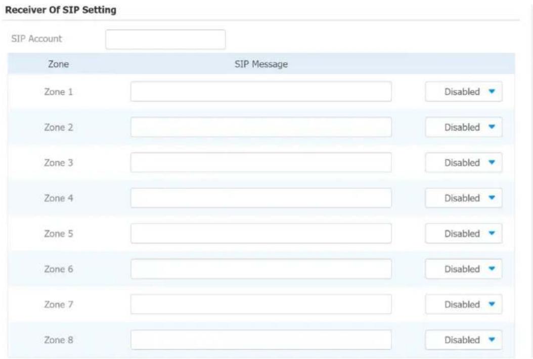
Receiver Of SIP Setting
Call Setting
Parameter Set-up:
- HTTP Command: enable HTTP command if you want the action to be implemented on a designated third party device
- SIP Message: enable SIP message if you want the SIP message to be sent to a designated SIP account as an action
- Call: enable Call if you want you a call to go to a designated SIP or IP number.
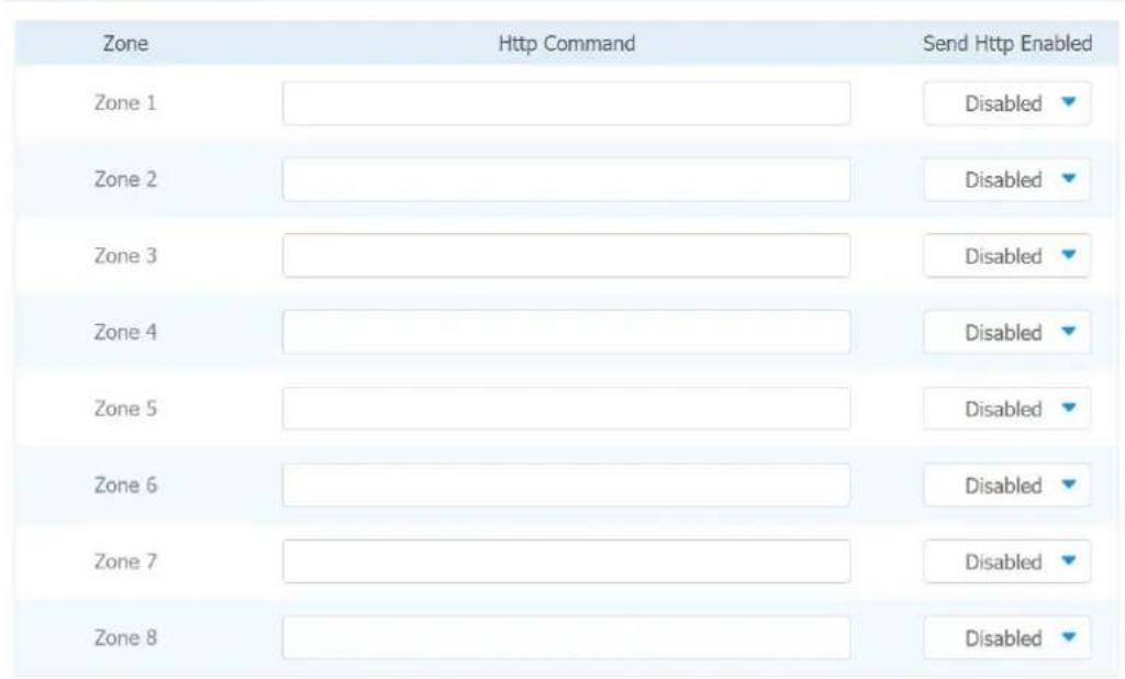
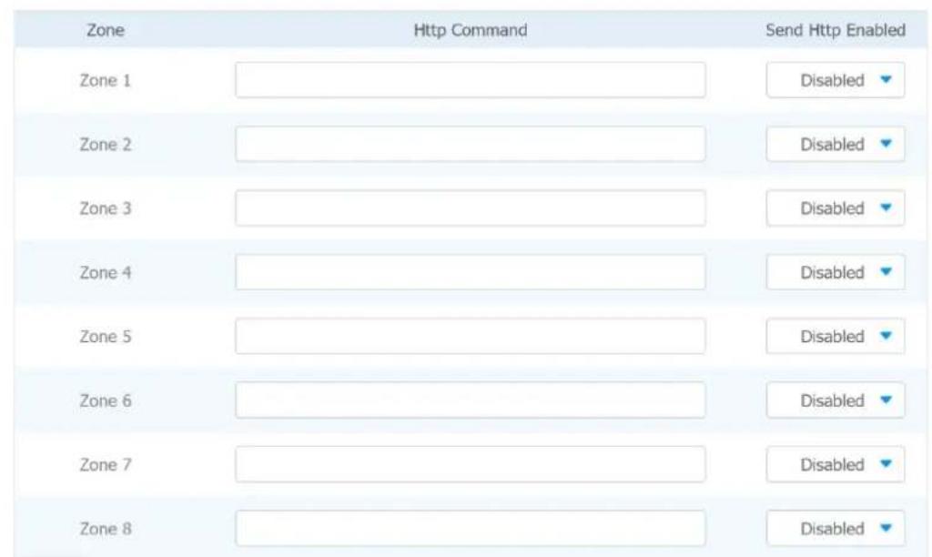
1.43.7.2. Configure Alarm Action via HTTP Command
To set up the HTTP Command action, you can click "Enable" in the Send HTTP field to enable the actions for the alarm sensor installed in different locations. Then enter the HTTP command provided by the manufacturer of the device on which the action is to be carried.
HTTP Command Setting
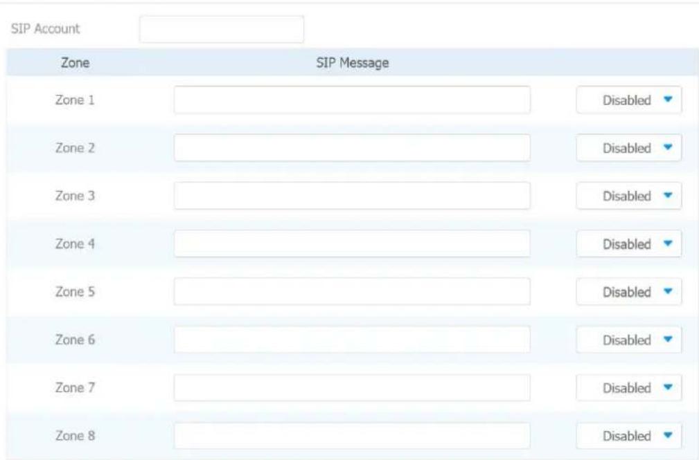
1.43.7.3. Configure Alarm Action via SIP Message
To set up the SIP message action receiver on the same web interface. Enter the SIP account to which you want to send the configured SIP message as an action when the alarm is triggered.
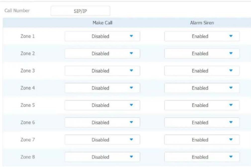
1.43.7.4. Configure Alarm Action via SIP Call
To set up the call action, you can enter the SIP or IP number of the device to be called as an action, then enable Alarm Siren for arming zone as needed.
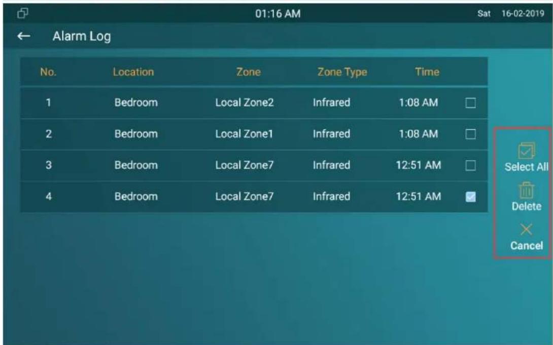
1.43.8. Check Alarm Log
To check alarm log on device Settings > Alarm Log screen. To delete the existing alarm log by clicking the right side operation icon.
1.44.Screen Unlock Setting
You can enable screenlock function directly on the device Settings > Display screen.
The device screen will be locked over the sleep time. You are required to wake up the device through the face recognition (Face ID) or password.
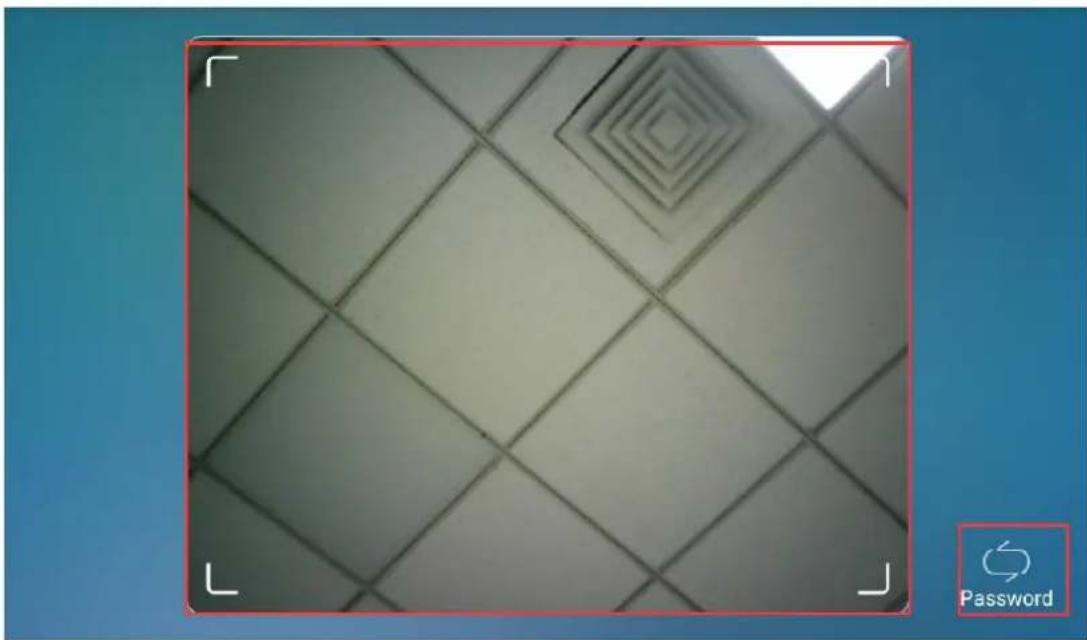
1.44.1. Screen Unlock by Face ID
You can unlock device screen by scanning the pre-configured face. To register the face on device Advance Settig > Face ID. Click Add and agree the privacy agreement. Then looking the camera to put your face into the frame on the screen to register.
natural_image
Close-up of a tiled floor with concentric diamond patterns and a 'Password' button icon in the corner (no other text or symbols)1.44.2. Screen Unlock by PIN Code
You can unlock device screen by entering the pre-configured PIN code when the screen is locked.
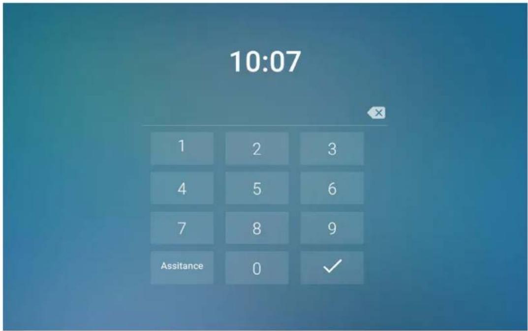

Note:
- Default unlock PIN is 123456.
1.45. Voice Encryption
The encryption function provides you with greater security for the intercom call. And Akuvox indoor monitors support three modes of voice encryption: SRTP(compulsory), SRTP(Optional), ZRTP(Optional) on web Account > Advanced > Encryption interface.
Encryption
Voice Encryption
Disabled

Parameter Set-up:
- Voice Encryption: select encryption mode from four options. If you select to Disable it, the call will not be encrypted. SRTP(Compulsory), all audio signals (technically speaking it is RTP streams) will be encrypted to improve security. SRTP(Optional), encrypts voice from the called party, if the called party also enables SRTP, the voice signals will also be encrypted. ZRTP(Optional) is the protocol that the two parties use to negotiate the SRTP session key.
1.46.Remote Control
Remote control function supports configuring a specific server to send HTTP commands or request to the indoor monitor to do some specific action on web Phone > Call Feature > Remote Control interface.
Remote Control
Allowed Access IP List
1.47.Relay Switch Setting
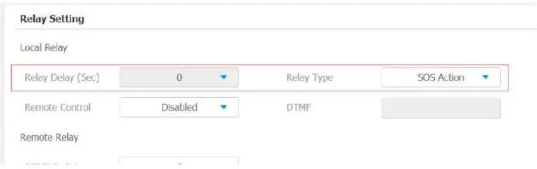
1.47.1. Local Relay Setting
Local relays in Akuvox indoor monitor can be used to trigger relay for the door access and trigger Chime bell as needed in different scenarios. You can do this configuration on web Phone > Relay > Relay Setting > Local Relay interface.
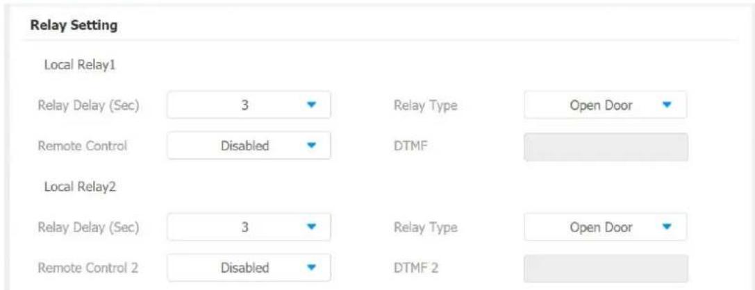
Parameter set-up:
- Relay Delay: set the relay delay time after the relay is triggered.
- Relay Type: set relay action type. There are two types of relay, chime bell and open door. Chime Bell, when there is a call, the chime bell will ring. Open door, when press the unlock icon, the local relay will be opened.
- Remote Control: enable it to trigger local relay by DTMF and vice versa.
1.47.2. Remote Relay Switch Setting
You can use the unlock tab during the call to open the door on web Phone > Relay > Relay Setting > Remote Relay interface. You are required to set up the same DTMF code in the door phone and indoor monitor.
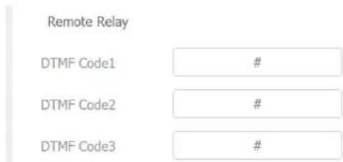
Parameter Set-up:
- DTMF Code: To set DTMF code for the remote relay, which is “#” by default.
1.48.Web Relay Setting
In addition to the relay that is connected to indoor monitor, you can also control the door access using the network-based web relay. To do this configuration on web Phone > Relay > Web Relay interface.
Akuvox Smart Intercom
Android Indoor Monitor Administrator Guide
Web Relay
IP Address

UserName

Password
●●●●●●●
Web Relay Action Setting
| Action ID | IP | SIP | Web Relay Action |
| Action ID 01 | |||
| Action ID 02 |
Parameter Set-up:
- IP address: enter the web relay IP address.
- User Name: enter the User name provided by the web relay manufacturer.
- Password: enter the password provided by the web relay manufacturer. The passwords is authenticated via HTTP and you can define the passwords using "http get" in Action.
- Web Relay Action: enter the specific web relay action command provided by the web manufacturer for different actions by the web relay.
- IP/SIP: enter the relay extension information, which can be a IP address or SIP account of an intercom device such as an indoor monitor, so that the specific action command will be sent when unlock is performed on the intercom device, while this setting is optional. And please refer to the example below:
http://admin:admin@192.168.1.2/state.xml?relayState=2.
1.49. Door Unlock Configuration
1.49.1. Door Unlock by DTMF Code
AKUVOX SMART INTERCOM www.akuvox.com
DTMF codes can be configured on the web Account > Advanced > DTMF interface where you can set up identical DTMF code on the corresponding intercom devices, which allows residents to enter the DTMF code on the soft keypad or press DTMF code attached unlock tab on the screen to unlock the door for visitors etc., during a call.

Parameter Set-up:
- Type: select DTMF type among four options: "Inband", "RFC2833", "Info+Inband" and "Info+RFC2833" according to your need.
- How to Notify DTMF: select among four options: "Disable" "DTMF" "DTMF-Relay" "Telephone-Event" according to your need.
- DTMF Payload: select the payload 96-127 for data transmission identification.

Note:
- Please refer to the chapter Relay Switch Setting for the specific DTMF code setting. Intercom devices involved must be consistent in the DTMF type, otherwise DTMF code cannot be applied.
1.49.2. Door Unlock via HTTP Command
You can unlock the door remotely without approaching the device physically for the door access by typing the created the HTTP command (URL) on the web browser to trigger the relay when you are not available by the door for
the door access. To do this configuration on web Intercom > Relay > Open Relay Via HTTP interface.
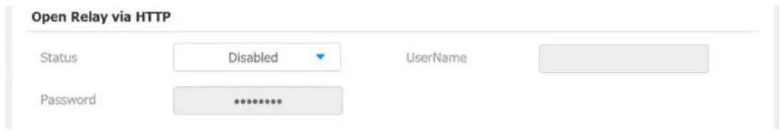
Parameter Set-up:
- Status: Enable it to allow the relay to be triggered remotely using HTTP command.
- Username: Enter the device username to be used as a part of HTTP command to trigger the local relay.
- Password: Enter the device password to be used as part of HTTP command to trigger the local relay.
Please refer to the following example:
http://192.168.35.127/fcgi/do?action=OpenDoor&UserName=admin&Password=12345&DoorNum=1

Note:
- DoorNum in the HTTP command above refers to the relay numb #1 to be triggered
1.49.3. Unlock by Icon Button
To setup the touch unlock key in IT82X for unlock on web Phone >Key/Display interface.
1.49.4. Unlock by SOS Call
To choose the Relay type as SOS Action on web Phone > Relay interface. When call out the SOS number, the relay will be triggered.
Lift Control
You can summon lift at home via lift control feature.
1.50.Configure Lift Control
To enable and set the display status Lift icon on device web Phone > Lift> Lift Control interface.
Lift Control
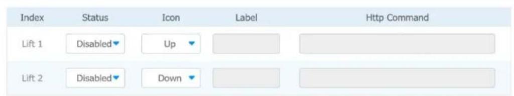
Parameter set-up:
- Status: click to enable or disable the lift1 button.
- Icon: click to select icon for the button.
- Label: enter the title for the button.
- HTTP Command: select http:// or https:// for head of http command and enter http command.
1.51.Configure Lift Control Prompt
When the lift controller receive the HTTP command, it will feedback the current lift status with a prompt. To do this configuration on web Phone > Lift> Hints interface. Edit the HTTP Status Code, feedback code from Lift control board.
Hints
| Index | HTTP Status Code | Lift | Hints |
| 1 | 200 | Lift 1 | Lift is coming to your floor |
| 2 | 200 | Lift 2 | Lift has been sent to Ground Floor |
| 3 |
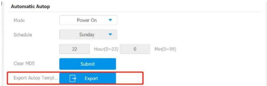
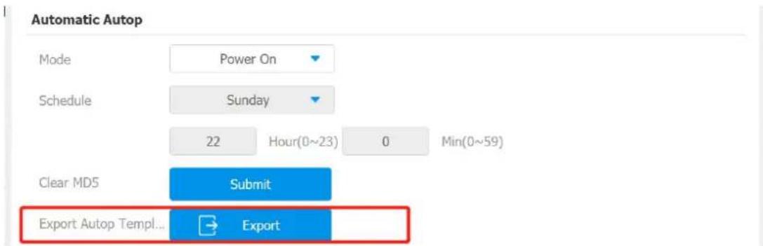
If there are huge amounts of prompts need to be add, you can click Export tab to export a template, after editing to import/export.
Hints Import/Export
Import(.xml)
Export
Not selected any files
Export
Select File
→ Import
× Cancel
Firmwares of different versions for indoor monitor can be upgraded on the device web Upgrade > Basic interface.


Note:
- Firmware files should be .zip format for upgrade.
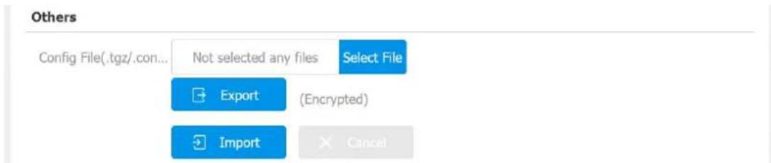
Backup
Configuration files can be imported to or exported out of the device to your local PC on the device web Upgrade > Advanced > Others interface if needed.
Auto-provisioning via Configuration File
1.52.Provisioning Principle
Auto-provisioning is a feature used to configure or upgrade the devices in batch via third party servers. DHCP, PNP, TFTP, FTP, HTTPS are the protocols used by the Akuvox intercom devices to access the URL of the address of the third party server which stores configuration files and firmwares, which will then be used to update the firmware and the corresponding parameters on the door phone.
Please see the flow chart below:
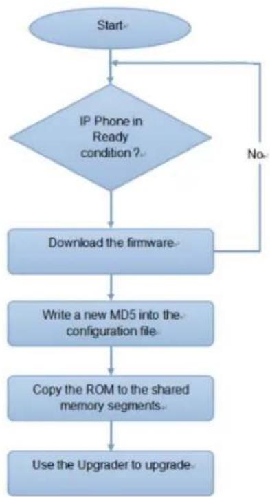
flowchart
graph TD
    A["Start"] --> B{IP Phone in Ready condition?}
    B -->|No| C["Download the firmware"]
    B -->|Yes| D["Start"]
    C --> E["Write a new MD5 into the configuration file"]
    E --> F["Copy the ROM to the shared memory segments"]
    F --> G["Use the Upgrader to upgrade"]
1.53. Introduction to the Configuration Files for Auto-Provisioning
Configuration files have two formats for the auto-provisioning. one is the general configuration files used for the general provisioning and other one is the MAC-based configuration provisioning.
The difference between the two types of configuration files is shown as below:
- General configuration provisioning: a general file is stored in a server from which all the related devices will be able to download the same configuration file to update parameters on the devices. For example cfg.
- MAC-based configuration provisioning: MAC-based configuration files is used for the auto-provisioning on a specific device as distinguished by its unique MAC number. And the configuration files named with device MAC number will be matched automatically with the device MAC number before being downloaded for the provisioning on the specific device.

Note:
- If a server has these two types of configuration files, then IP devices will first access the general configuration files before accessing the MAC-based configuration files.
1.54 Autop Schedule
Akuvox provides you with different Autop methods that enable the indoor monitor to perform provisioning for itself in a specific time according to your
schedule. To set up the schedule on device web Upgrade > Advanced > Automatic Autop interface.
Please see the picture below:
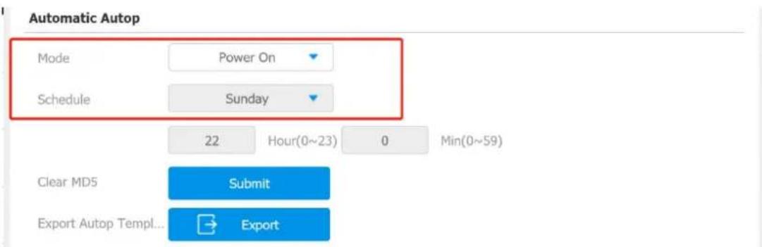
Parameter Set-up:
- Power On: select "Power on", if you want the device to perform Autop every time it boots up.
- Repeatedly: select "Repeatedly", if you want the device to perform autop according to the schedule you set up.
- Power On + Repeatedly: select "Power On + Repeatedly" if you want to combine Power On Mode and Repeatedly mode that will enable the device to perform Autop every time it boots up or according to the schedule you set up.
- Hourly Repeat: select "Hourly Repeat" if you want the device to perform Autop every hour.
1.55.DHCP Provisioning Configuration
Auto-provisioning URL can also be obtained using DHCP option which allows device to send a request to a DHCP server for a specific DHCP option code. If you want to use Custom Option as defined by users with option code range
from 128-255), you are required to configure DHCP Custom Option on the web Upgrade > Advanced > Automatic Autop interface.
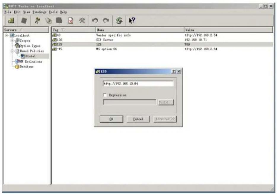

Note:
- The custom Option type must be a string. The value is the URI TFTP server.
DHCP Option
Custom Option
(128\~254)
DHCP Option Enable
√ Custom Option
Option 43
Option 66
Parameter set-up:
- Custom Option: enter the DHCP code that matched with corresponding URL so that device will find the configuration file server for the configuration or upgrading.
- DHCP Option 66: If none of the above is set, the device will automatically use DHCP Option 66 for getting the upgrade server URL. This is done within the software and the user does not need to specify this. To make it work, you need to configure the DHCP server for the option 66 with the update server URL in it.
- DHCP Option 43: If the device does not get an URL from DHCP Option 66, it will automatically use DHCP Option 43. This is done within the software and the user does not need to specify this. To make it work, you need to configure the DHCP server for the option 43 with the update server URL in it.

Note:
- The general configuration file for the in-batch provisioning is with the format "cfg" taking R29 as an example "r000000000029.cfg (10 "zeros" in total while the MAC-based configuration file for specific device provisioning is with the format "MAC_Address of the device.cfg, for example "OC110504AE5B.cfg."
1.56.Static Provisioning Configuration
You can manually set up a specific server URL for downloading the firmware or configuration file on device web Upgrade > Advanced > Automatic Autop interface. If an autop schedule is set up, the indoor monitor will perform the auto provisioning on a specific timing according to autop schedule you set up. In addition, TFTP, FTP, HTTP, and HTTPS are the protocols that can be used for upgrading the device firmware and configuration.
Manual Autop
URL
tftp://192.168.35.77
User Name
admin
Password
●●●●●●●●
Common AES Key
●●●●●●●
AES Key(MAC)
●●●●●●●●
AutoP Immediately
Parameter set-up:
- URL: set up TFTP, HTTP, HTTPS, ftp server address for the provisioning
- User Name: set up a user name if the server needs an user name to be accessed to otherwise leave it blank.
- Password: set up a password if the server needs a password to be accessed to otherwise leave it blank.
- Common AES Key: set up AES code for the intercom to decipher general Auto Provisioning configuration file.
- AES Key (MAC): set up AES code for the intercom to decipher the MAC-based auto provisioning configuration file.

Note:
- AES is one type of encryption, it should be configured only when the config file is encrypted with AES, otherwise leave the field blank.

Note:
- server Address format:
• TFTP: tftp://192.168.0.19/
- FTP: ftp://192.168.0.19/ (allows anonymous login)
- ftp://username:password@192.168.0.19/(requires a user name and password)
- HTTP: http://192.168.0.19/ (use the default port 80)
- http://192.168.0.19:8080/ (use other ports, such as 8080) HTTPQ: https://192.168.0.19/ (see the default port 442)

Tip:
- Akuvox do not provide user specified server.
- Please prepare TFTP/FTP/HTTP/HTTPS server by yourself.
You can configure voice assistant named "Albert" to perform a variety of functions related to intercom call, open-door, arming modes etc. on the device. and you can also set up the specific relay to be triggered by the voice assistant for the door access control. To configure the voice assistant on device Settings > Voice Assistance screen.
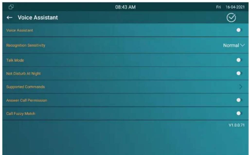
Parameter Set-up
● Language Type: select the language according to your need.
● Recognition Sensitivity: adjust the voice assistance recognition sensitivity among "Low", "Normal" and "High" according to your need.
- Talk Mode: move the toggle switch to the righ if you want to enable the the talk mode. When the Talk mode is enabled, voice assistant will stay on to receive your voice commands during a time span of 30 seconds without your needing to call "Albert" again to wake up the voice assistant., while if you disable it, the voice assistant will be wake up again for each voice command.
- Not Disturb At Night: move the toggle switch to the left to enable the function. This function is applied when you want the voice assistant to
stay silent while carrying out what it is made to do according to your voice commands.
- Supported Command: enable or disable the 22 voice commands according to your need.
Please see the voice command details below:
| NO | Voice Command | Description | Voice Prompt |
| 1 | Intruder mode off | Use it when you want to clear the arming mode when the arming alarm is triggered. (you are required to enter the dismarm password in the pop-out window initiated by the voice assisatant) | Please Input Password |
| 2 | Clear arming | ibid | ibid |
| 3 | night mode | Use it when you want to change the arming mode to night mode | Started it, sweet dreams!Made it, good nightSure, sleep mode is oOK, start sleep mode, have a good nightAlright, sleep mode is opened, have a nice dream |
| 4 | sleep mode | Use it when you want to change the arming mode to sleep mode | Sure, sleep mode is oOK, start sleep mode, have a good nightAlright, sleep mode is opened, have a nice dreamMade it, good nightStarted it, sweet dreams! |
| 5 | away mode | Use it when you want to change the arming mode to away mode | Sure, away mode is onOK, start away modeAlright, away mode is openedMade itMade it, have a good dayDone, away mode is started |
| 6 | home mode | Use it when you want to change the arming mode to home mode | Sure, home mode is onOK, start home modeAlright, home mode is openedMade itDone, home mode is started |
| 7 | open door | Use it when you want to open the door | Sure, the door is openThe door is open for youNo problem, open the doorOpened, always here for youYep, door is opened now |
| 8 | open the door | Use it when you want to open the door | Sure, the door is openThe door is open for youNo problem, open the doorOpened, always here for youYep, door is opened now |
| 9 | disable DND | Use it when you want to disable the DND mode | Yes, closed it for youWelcome back, DND is offDND is closed, to mingle with the worldSure, DND is off |
| 10 | enable dnd | Use it when you want to enable the DND mode | OK, dnd is onDone, enjoy yourselfDND is on, feel your inner peaceTurn on it now |
| 11 | emergency | Use it when you want to dial SOS number | Got it, calling sos as soon as possibleOkay, be relaxed, making a emergency call nowCalling ambulance nowCalling sos now, please hold onGod bless you, calling emergency nowHold on please, calling emergency right nowTake it easy, calling emergency right now |
| 12 | help me | ibid | ibid |
| 13 | call manager | use it when you want to call "manager" you name set up in the phonebook | Please choose one for callingsorry I didn't get that |
| 14 | call staff | use it when you want to call "stuff" you named and set up in the phonebook | Please choose one for callingsorry I didn't get that |
| 15 | call carer | use it when you want to call "carer" you named and set up in the phonebook | Please choose one for callingsorry I didn't get that |
| 16 | open message | use it when you want to check text message. | Got it, please checkOK, message is opened, you can write some contents to sendMessage is ready for youalready opened it foryou |
| 17 | open monitor | use it when you want to check monitor | Got it ,please check |
| 18 | homepage | use it when you want to to home screen | Home page is already for you.Already got it for you |
| 19 | enable mute | use it when you want to mute your voice on the indoor monitor so that th caller or callee will be no be able to hear you. | OK, mute is onDone, enjoy yourselfMute is on, feel your inner peaceSet it now |
| 20 | disable mute | use it when you want to unmute your voice on the indoor monitor so that th caller or callee will be be able to hear you. | Sure, mute is offMute is closed, to mingle with the worldWelcome back, mute is offYes, closed it for you |
| 21 | cancel | ||
| 22 | shut down | Use it when you want to turn off the voice assista function | See youSee you laterByeGood byeSee you next timeBye, best regardsSee you, have a great time |
- Answer Call Permission: enable it when you so that you can answer or reject the incoming call via voice assistant by replay "Yes" or "No"
- Call Fuzzy Match: Enable it to allow fuzzy matching of the contact name, for example, if you have Tom and Tomy in your phonebook, then Tomy will also appear when you call "Tom", and you are required to select the right contact manually.
To enable the voice assistant and set the voice assistant-controlled relay on the web Device Setting > Voice Assistant interface, you can tick the check box to enable the voice assistant function. Then go to Voice Command Setting section to elect specific relay to bet triggered via voice assistant.
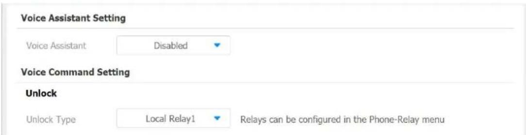
Call Log
If you want to check on the calls inclusive of the dial-out calls, received calls, and missed calls in a certain period of time, you can check and search the call log on the device web Contacts > Call Logs interface and export the call log from the device if needed.
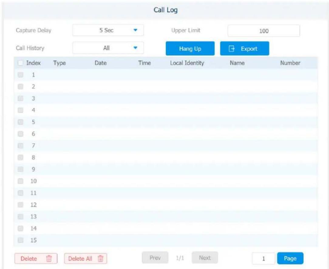
Parameter Set-up:
● Capture Delay: set the image capturing starting time when the device goes into video preview.
● Upper Limit: set the maximum screenshot storage capacity, when the capacity is reached the previous screenshots would be overwritten.
- Call History: select call history among four options: "All", "Dialed" "Received" "Missed" for the specific type of call log to be displayed.
Debug
1.57.System Log for Debugging
System log in the indoor monitor can be used for debugging purpose. If you want to export the system out to a local PC or to a remote server for debugging, you can set up the function on the web Upgrade > Advanced > System Log interface.

Parameter Set-up:
- LogLevel: select log levels from 1 to 7 levels. You will be instructed by Akuvox technical staff about the specific log level to be entered for debugging purpose. The default log level is "3".the higher the level is, the more complete the log is.
- Export Log: click the Export tab to export temporary debug log file to a local PC.
- Export Debug Log: click the Export tab to export debug log file to a local PC.
- Remote System Log: select "Enable" or "Disable" if you want to enable or disable the remote system log.
- Remote System Server: enter the remote server address to receive the device And the remote server address will be provided by Akuvox technical support.
1.58. PCAP for Debugging
PCAP in Akuvox indoor monitor is used to capture the data package going in and out of the devices for debugging and troubleshooting purpose. You can set up the PCAP on the device web Upgrade > Advanced > PCAP interface properly before using it.
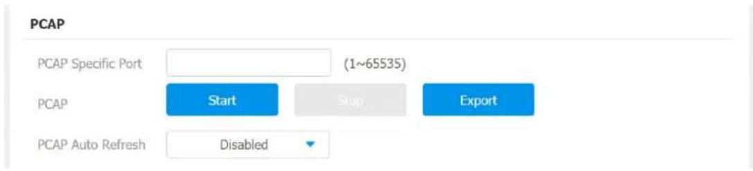
Parameter set-up:
- Specific Port: select the specific ports from 1-65535 so that only the data packet from the specific port can be captured. You can leave the field blank by default.
- PCAP: clickStart tab and Stop tab to capture the a certain range of data packets before clicking Export tab to export the data packets to you Local PC.
- PCAP Auto Refresh: select "Enable" or "Disable" to turn on or turn off the PCAP auto fresh function. If you set it as "Enable" then the PCAP will continue to capture data packet even after the data packets reached its 50M maximum in capacity. If you set it as "Disable" the PCAP will stop data packet capturing when the data packet captured reaches the maximum capturing capacity of 1MB.
1.59. User Agent
User agent is used for the identification purpose when you are doing analysis on the SIP data packet. To do this configuration on web Account > Advanced interface.
User Agent ②
User Agent
Device Integration with Third Party
1.60.Enter Applications Screen
AKUVOX SMART INTERCOM www.akuvox.com
The content of this part mainly teaches you how to enter the APK interface through hidden operations. To do the configuration on device Settings > System Info interface. you can press on User Mode for 10 times and press "Admin Mode" and press "Confirm" for the confirmation
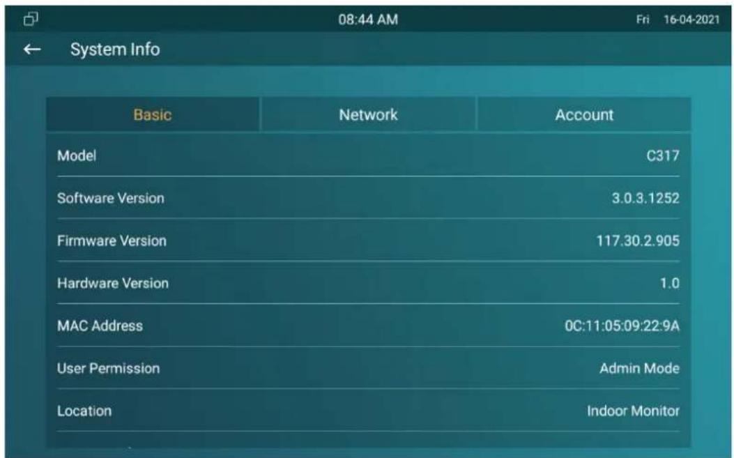
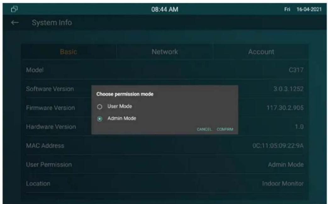
1.61. Install Third-party App
You can install the third-party App to your device on the device web Phone > App interface. Choose a suitable .apk file from PC to upload.
App Install
File(.apk):
Not selected any files
Select File
To configure the installed the third-party app on web Phone > Key/Display > Third Party APK Control, you can click App Name field to select the specific name of the installed APK files for configuration. Then tick the check boxes of the each field for specific configuration you need.
Third Party APK Control
App Name

Start Up Enable
Disabled

Turn Back Apk Enable
Disabled

Intervals Without O...


Turn Back Apk After...
Enabled

Show App Icon
Enabled

APP Keep-Alive
Disabled

Turn Back Apk After...
Disabled

Parameter Set-up:
- App Name: select the App Name to be configured.
- Interval Without Operating (Sec): tick the check box to set the app returing time-interval when there is no operation on the device.
-
Start Up Enable: tick the check box of Start UP Enable if you want to the app to be run automatically when the device is turned on.
-
Turn Back App After Awakening: tick the check box of if you want the device to return to the app when the screen is awakened.
- APP Keep-Alive :tick the check box of if you want the app to stay runing without being turn off.
- Turn Back App After Calling: tick the box if you want the app to return automatically after finishing a call ( This features applies to all the apps).
● Show App Icon: tick the box if you wabt the app icon to be displayed on the screen.
Password Modification
1.62.Modify Device Basic Setting Password
To do the configuration on device Advance Settings > System Code screen to change a new password. The default password is 123456.
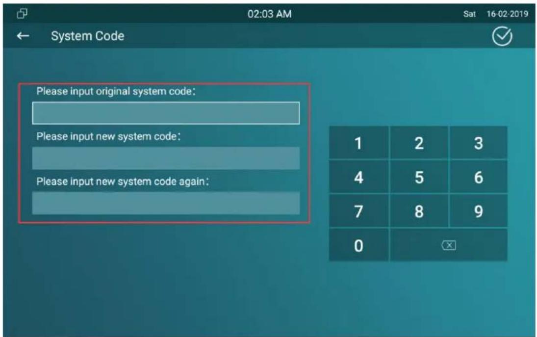
1.63.Modify Device Advanced Setting Password
This password is used to enter the advanced settings of the device, including password settings, account numbers, SOS numbers, network settings, etc. To modify the advanced setting password on device Advanced Settings > Setting Code screen. The default password is 123456.
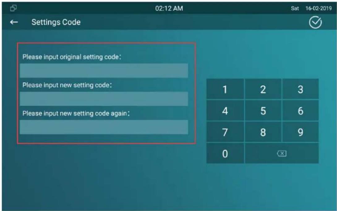
1.64.Modify Device Web Interface Password
To modify web interface password, you can do it on device web Security > Basic > Web Password Modify interface. Select "Admin" for the administrator account and "User" for the User Account. Click the Change Password tab to change the password.
Web Password Modify
User Name
admin
Change Password

Note:
- There are two accounts, one is admin, its password is admin, the other is user, its password is user.
1.65.Modify Browser Password
This password is used to lock the browser on the device in case someone abuses the browser for any unwanted application. You can do this configuration on device Advance Settings > App Protected Code screen. The default password is 123456.
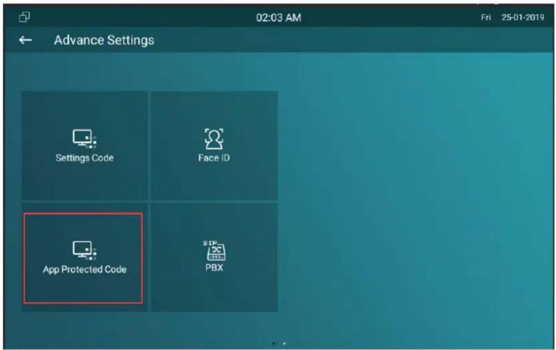
PBX Feature
IT83/C317 Android indoor monitor has built in the PBX server which makes the indoor station not only used as a intercom monitor also a SIP PBX, users do not bother to prepare an extra SIP PBX again. The PBX supports call, forward, transfer, conference, ring group feature and so on. You can set up on device screen or web interface.
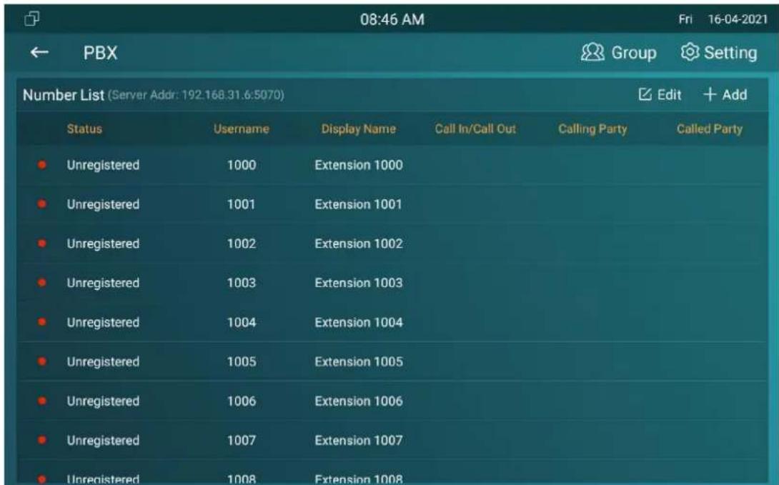
1.66.PBX Configuration on The Device
Enable the PBX feature on device Advance Settings > PBX screen to check and manage SIP accounts.
1.66.1. Enable PBX Service
In the PBX interface, click Setting on the right top corner enable the PBX.
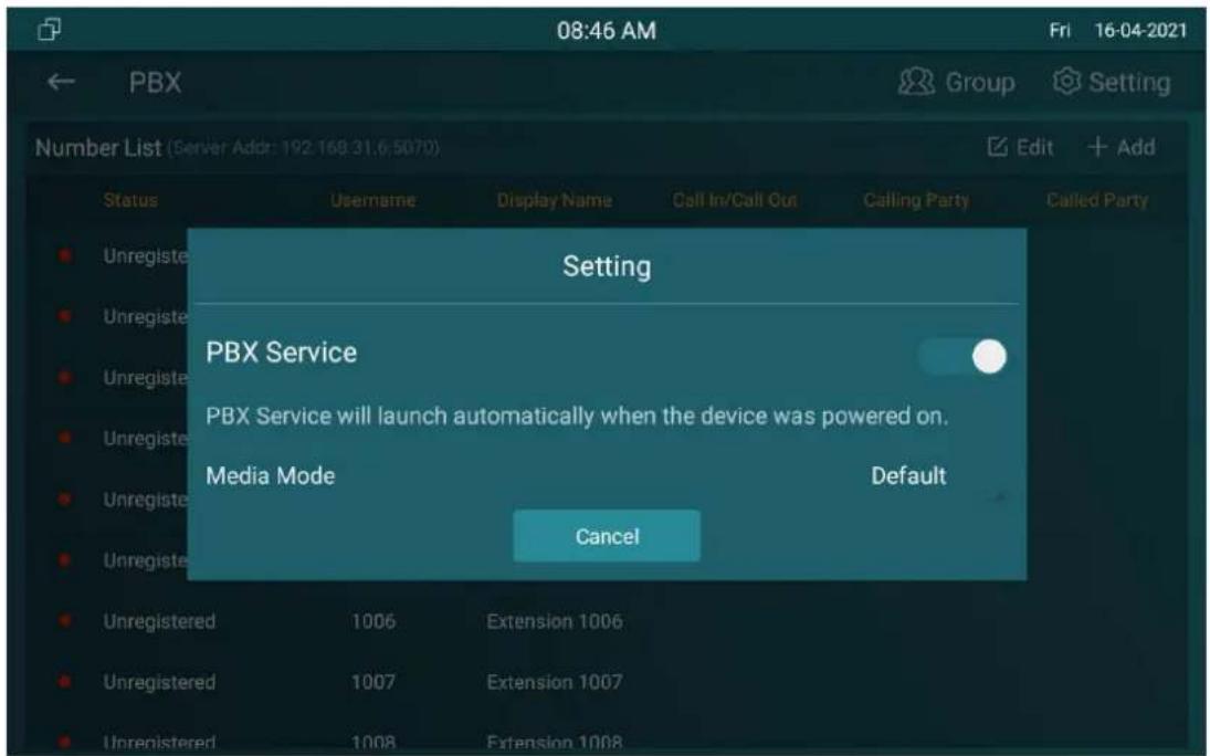
1.66.2. Manage PBX Accounts
You can check the basic PBX information like PBX server and port and accounts status.
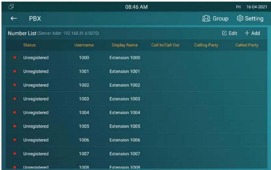
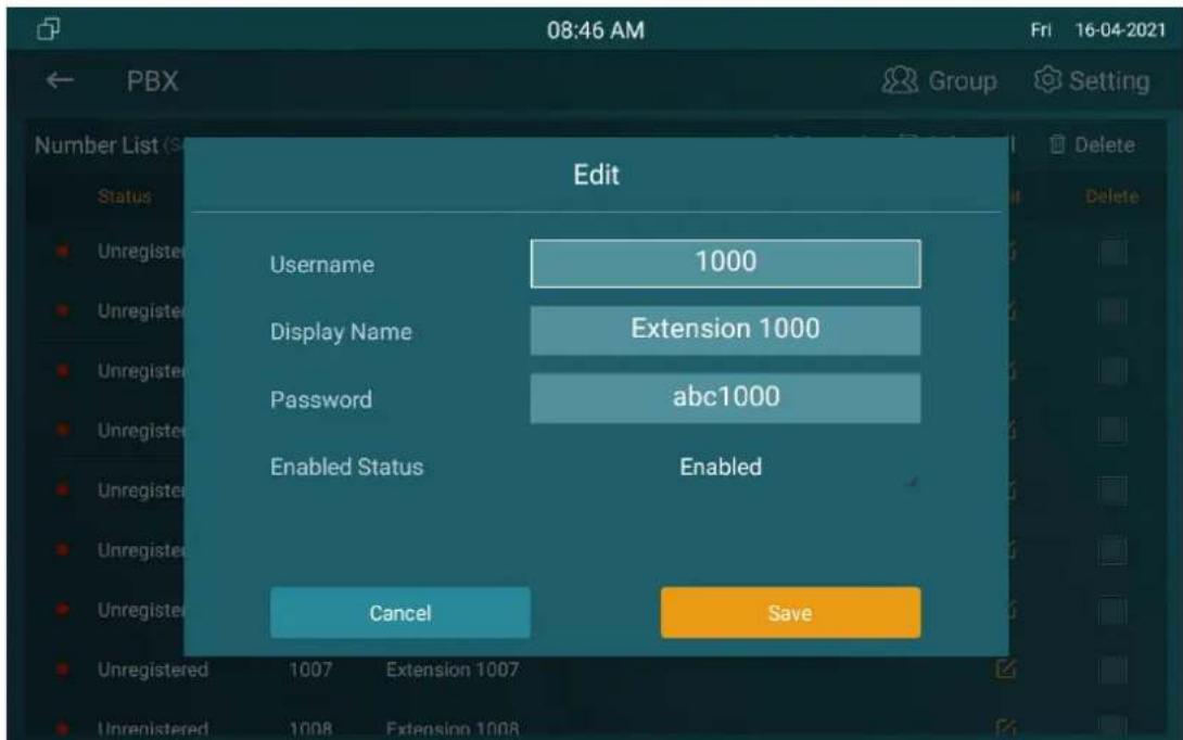
Parameter Set-up:
● Status: to show whether the account is registered or not.
- Username: To enter the extension number registered onto SIP server.
- Display Name: Tt enter the display name of this account, which will show on other devices when making calls.
- Password: to enter the password of the corresponding users.
● Enabled Status: to activate SIP account. - Call IN/Call Out: the calling status of this account.
- Calling Party: the calling party number.
- Caller Party: the caller party number.
1.66.3. Manage PBX Groups
Click Group on the right top corner to add a new ring group or edit the existing group. One number can be added in different ring groups. Once receiving an incoming call, the numbers in one group will be ring up at the same time.
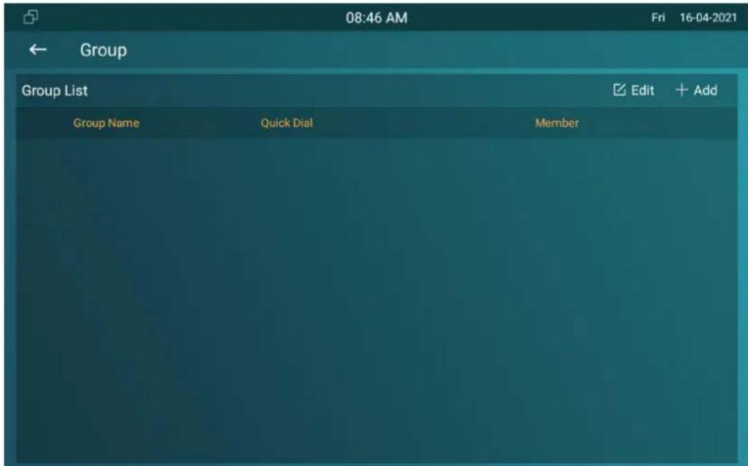
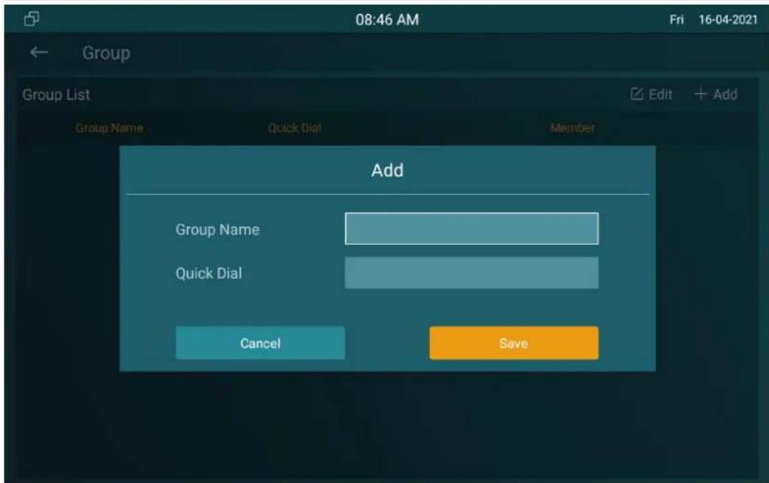
Parameter Set-up:
- Group Name: the name of a ring group.
● Quick Dial: a number of this ring group.
1.67.PBX Configuration on The Web Interface
You can do the same configuration on web PBX > Basic and PBX > Ring Group interface.
PBX-Basic
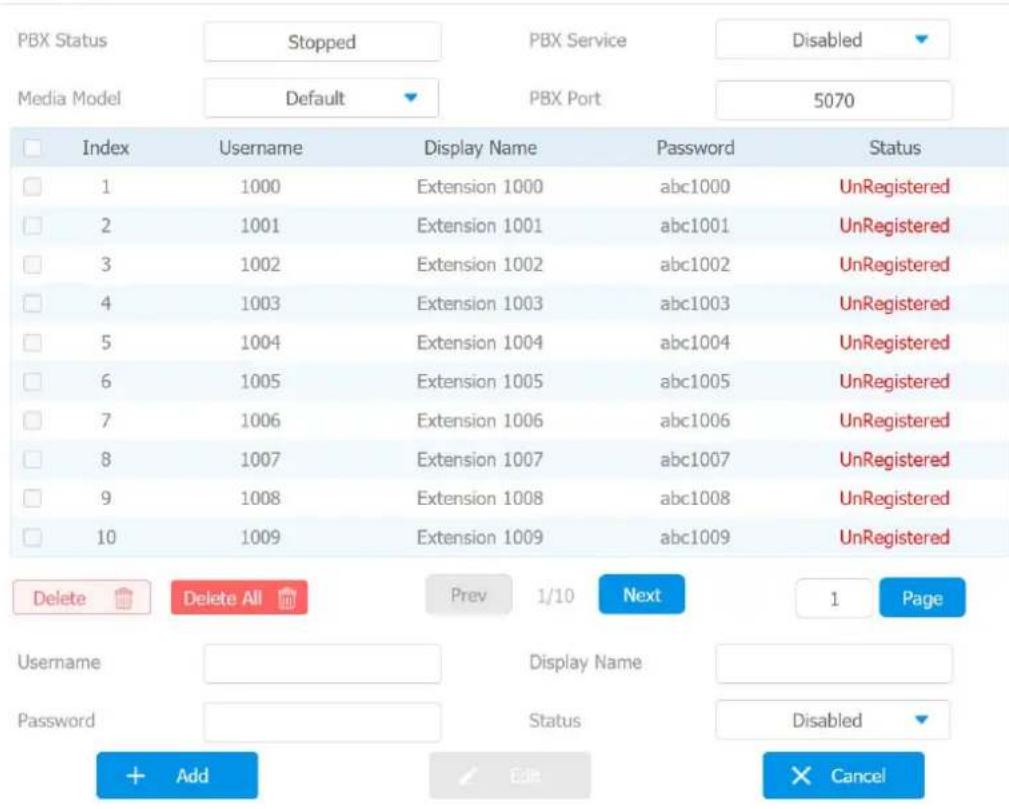
Group Settiing
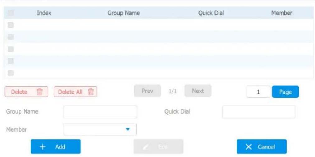
System Reboot&Reset
1.68.Reboot
1.68.1. Reboot on the Device
If you want to reboot the system setting of the device, you can operate it directly on the device setting screen or on the device web interface. To reboot to the system setting on device Settings >Reboot screen.
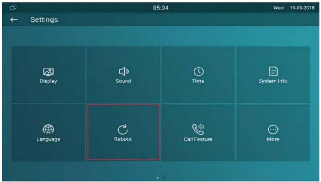
1.68.2. Reboot on the Web Interface
If you want to reboot the device system, you can operate it on the device web Upgrade > Basic interface as well. More over, you can set up schedule for the device to be restarted.
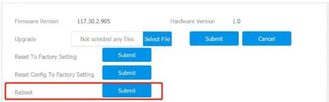
To set up the device reboot schedule on web Upgrade > Advanced > Reboot Schedule interface.
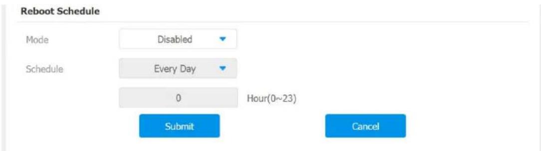
1.69. Reset
1.69.1. Reset on the Device
If you want to reset the whole device system to the factory setting, you can operate it directly on the device Advance Settings > Reset screen. If you only want to reset the configuration file to the factory setting instead of the whole device system, you can press Reset Config To Factory Setting tab.
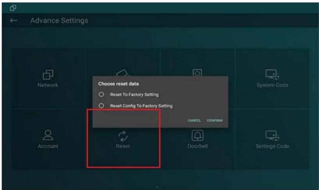
1.69.2. Reset on the Web Interface
Device system can also be reset on device web Upgrade > Basic interface without approaching the device. If you only want to reset to the configuration file to the factory setting, you can click Reset Config on the same page.
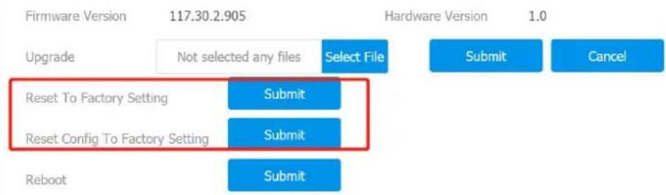
Abbreviations
ACS: Auto Configuration Server
Auto: Automatically
AEC: Configurable Acoustic and Line Echo Cancelers
ACD: Automatic Call Distribution
Autop: Automatical Provisioning
AES: Advanced Encryption Standard
BLF: Busy Lamp Field
COM: Common
CPE: Customer Premise Equipment
CWMP: CPE WAN Management Protocol
DTMF: Dual Tone Multi-Frequency
DHCP: Dynamic Host Configuration Protocol
DNS: Domain Name System
DND: Do Not Disturb
DNS-SRV: Service record in the Domain Name System
FTP: File Transfer Protocol
GND: Ground
HTTP: Hypertext Transfer Protocol
HTTPS: Hypertext Transfer Protocol Secure Socket Layer
IP: Internet Protocol
ID: Identification
IR: Infrared
LCD: Liquid Crystal Display
LED: Light Emitting Diode
MAX: Maximum
POE: Power Over Ethernet
PCMA: Pulse Code Modulation A-Law
PCMU: Pulse Code Modulation μ-Law
PCAP: Packet Capture
PNP: Plug and Play
RFID: Radio Frequency Identification
RTP: Real-time Transport Protocol
RTSP: Real Time Streaming Protocol
MPEG: Moving Picture Experts Group
MWI: Message Waiting Indicator
NO: Normal Opened
NC: Normal Connected
NTP: Network Time Protocol
NAT: Network Address Translation
NVR: Network Video Recorder
ONVIF: Open Network Video Interface Forum
SIP: Session Initiation Protocol
SNMP: Simple Network Management Protocol
STUN: Session Traversal Utilities for NAT
SNMP: Simple Mail Transfer Protocol
SDMC: SIP Devices Management Center
TR069: Technical Report069
TCP: Transmission Control Protocol
TLS: Transport Layer Security
TFTP: Trivial File Transfer Protocol
UDP: User Datagram Protocol
URL: Uniform Resource Locator
VLAN: Virtual Local Area Network
WG: Wiegand
FAQ
Q1: How to obtain IP address of X933
A1: You can use the display screen to get the IP information, just check the IP address at setting, basic info.
You can also use Akuvox IP Scanner to search Akuvox devices in the same LAN network.
Q2: Do Akuvox devices support opus codec?
A2: For now, only Akuvox Android video IP phone R48G can support Opus audio codec. Door phone and indoor monitor still not supports.
Q3: What is the resolution of the 7 inch touch screen of X933?
A3: The ratio is 16:10, and resolution is 1280*800.
Q4: What operation system is X933?
A4:X933 based on Android 9.0.
Q5: Can I install apps at Akuvox indoor monitor?
A5:Akuvox have indoor monitor based on Linux system and Android system. For Linux system device (IT80/IT81/C312/C313 series), no possibe to install third party app. For android system device(C315/C317/IT83/IT83/X933 series),You can install third party apps as your wish.
Q6: Can I connect electrical lock to indoor monitor?
A6:Akuox indoor monitor have relay component, so you can connect electrical lock to indoor monitor.
Q7: Can I communicate other indoor monitor with indoor monitor?
A7:Akuvox device can communicate with each other, no matter it is indoor monitor,door phone or ip phone. Of course indoor monitor can call to other indoor monitor, also if you want, you can set other indoor monitor as auto answer mode.
Contact US
For more information about the product, please visit us atwww.akuvox.com or feel free to contact us by
Sales email: sales@akuvox.com
Technical support email: support@akuvox.com
Telephone: +86-592-2133061 ext.7694/8162
We highly appreciate your feedback about our products.