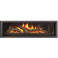
Greenfire GF1500L - Heating Regency - Free user manual and instructions
Find the device manual for free Greenfire GF1500L Regency in PDF.


| Product Type | Gas Fireplace |
| Brand | Regency |
| Model | Greenfire GF1500L |
| Dimensions (W x H x D) | 48 x 24 x 16 inches (approx.) |
| Weight | 175 lbs (approx.) |
| Fuel Type | Natural Gas or Propane (convertible) |
| BTU Rating | 15,000 BTUs/hr (input) |
| Heating Area | Up to 1,000 sq ft |
| Efficiency | 75% AFUE (approx.) |
| Ignition Type | Electronic intermittent pilot (IPI) |
| Control Type | Remote control with thermostat |
| Flame Adjustment | Variable flame control |
| Venting | Direct vent (coaxial) |
| Glass Viewing Area | Ceramic glass, high temperature resistance |
| Finish Options | Black, brushed stainless steel |
| Safety Features | Flame sensor, oxygen depletion sensor, cool-to-touch glass |
| Annual Maintenance | Clean glass, inspect burner, check venting |
| Warranty | Limited lifetime (combustion chamber), 5 years parts |
Frequently Asked Questions - Greenfire GF1500L Regency
User questions about Greenfire GF1500L Regency
0 question about this device. Answer the ones you know or ask your own.
Ask a new question about this device
Download the instructions for your Heating in PDF format for free! Find your manual Greenfire GF1500L - Regency and take your electronic device back in hand. On this page are published all the documents necessary for the use of your device. Greenfire GF1500L by Regency.
USER MANUAL Greenfire GF1500L Regency
Greenfire® GF1500L Gas Fireplace
Owners & Installation Manual

natural_image
Modern home wall with a black wall-mounted gas stove and visible flames, set against a white wall and wooden rug (no text or symbols)LISTINGS AND CODE APPROVALS
These gas appliances were tested in accordance with AS/NZS 5263.0 & AS/NZS 5263.1.3/ and certified by the Australian Gas Association for installation and operation as described in these instructions. Must be installed as per AS/NZS 5601.
Your unit should be serviced annually by an authorised service person.
www.regency-fire.com.au
MODELS: GF1500NG Natural Gas
GF1500LLP-2 GF1500LULPG-2 Propane

Warning
Fire or explosion Hazard failure to follow safety warnings exactly could result in serious injury, death, or property damage.
Do not store or use gasoline or other flammable vapors and liquids in the vicinity of this or any other appliance.
WHAT TO DO IF YOU SMELL GAS
- Do not try to light any appliance.
- Do not touch any electrical switch: do not use any phone in your building. Leave the building immediately.
- Immediately call your gas supplier from a neighbour's phone. Follow the gas supplier's instructions.
- If you cannot reach your gas supplier, call the fire department.
Installation and service must be performed by a qualified installer, service agency or the gas supplier.
Installer: Please complete the details on the back cover and leave this manual with the homeowner. Homeowner: Please keep these instructions for future reference.
owner's information
To the New Owner:
Congratulations!
You are the owner of a state-of-the-art gas fireplace by REGENCY®. The GF1500L has been designed to provide you with all the warmth and charm of a wood fireplace at the flick of a switch. The GF1500L was approved by AGA for both safety and efficiency. As it also bears our own mark, it will provide you with economy, comfort, and security for many trouble-free years to come. Please take a moment now to acquaint yourself with these instructions and the many features of your RegenFireplace.
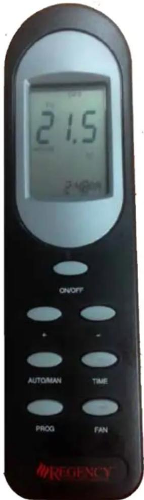
Pairing Your Remote Control
The control box will only learn the remote ID codes during the first 30 seconds after power is applied. After the first 30 seconds, the control box will ignore this special command.
The remote control handset has a set of unique ID codes that are pre-programmed into its memory. This set of ID codes helps differentiate one remote control handset from another. Only the control box with a matching ID code will respond to the appropriate remote control handset.
To match the control box, follow these steps:
- Ensure the remote is siwtched off.
- Remove the main power to the control box.
- Reconnect the main power to the control box.
- Press and hold the PROG and FAN buttons simultaneously. The temperature display will show the letters "LC", indicating the ID codes were transmitted, then revert to the normal off mode display.
- Release the PROG and FAN buttons.
The control box will only learn the remote ID codes during the first 30 seconds after power is applied and will ignore this special command from the remote afterward.
Fan Operation
The fan must be on while the unit is in operation. This model offers a two-speed fan.
NOTES
- The heater turns off when the room temperature reaches 1 C over the set temperature and turns back on when the room temperature reaches 0.50 C under the set temperature when in AUTO mode.
- The pairing process can be carried out by anyone.
- Please visit www.regency-fire.com.au to see the pairing video.
WARNING
DO NOT turn your fireplace on via any means or allow it to be turned on unless you have conducted a thorough inspection of the area surrounding the fireplace immediately prior to its use, and you have satisfied yourself that there are no materials or other items in proximity to the fireplace which could present a fire risk.
DO NOT turn your fireplace on via any means or allow to be turned on if there are any unsupervised children, infirm persons, or pets in the area surrounding the fireplace.
DO NOT use this fireplace unless you have read this manual, and strictly adhere to the user requirements and warnings set out in this manual.
RELEASE
Without limiting any other acknowledgement, release or indemnity given by you, or limitation of liability, in favour of Fireplace Products Pty Ltd ("Company"), you irrevocably and unconditionally acknowledge and agree that failure to comply with, or strictly adhere to, the requirements and warnings set out in this Manual ("User Requirements") may result in:
- damage to the fireplace;
- damage to property;
- a house fire;
- severe burns or other personal injury; and/or
- death.
Subject to any remedy, guarantee, term, condition, warranty, undertaking, inducement or representation, implied or imposed by any legislation which cannot lawfully be excluded or limited, and to the maximum extent permitted by law:
-
the Company will not be liable for any damage, personal injury or death arising out of or in connection with your failure to comply with any User Requirement; and
-
you release the Company from all claims, actions, proceedings, liabilities, losses and damages in relation to death, any personal injury or property damage arising out of or in connection with your failure to comply with any User Requirement.
table of contents
Owner's information
Pairing Your Remote Control 2
WARNING 3
RELEASE 3
Copy of Data Badge 5
Unit Dimensions 6
Installer's information
Important Message 7
General Safety Information 7
Installation Checklist 8
Locating Your Gas Fireplace 8
Installation
Clearances 9
Framing Dimensions 10
Combustible Finishing Unit Assembly/ Finishing/ Mantel Clearances + Mantel Leg Clearances .... 11
Framing & Finishing (Combustible)....12
Combustible Requirements 12
Clearances for Combustible Finishing with Mantel 13
Combustible Mantel Leg Clearances 13
Non Combustible Flush Finishing - Unit Assembly/Finishing/Mantel Clearances + Mantel Leg Clearances 14
Installation of Access Panel 14
Remove 8 standoffs 14
Clearances For Non Combustible Flush Finishing with Mantel ..... 15
Non Combustible Mantel Leg Clearances 15
Flushed Finishing & Framing with Non Combustible Material ..... 16
Non Combustible Requirements 16
Installing a TV / Artwork Flush with the Unit 17
TV Recess with 45 Degree Elbow ....18
TV Recess with Vertical Venting 18
Optional Framing Kit 19
Non Combustible Facing Installation 20
Framing & Finishing (Clean Finish Installations Only) 21
Exterior Flue Termination Locations 22
Exterior Flue Termination Locations - Clearances 23
127 mm x 203 mm Rigid Pipe - Cross Reference Chart Only ..... 24
Flue Restrictor Settings 26
Flueing Introduction 27
Flueing Arrangement for Horizontal Terminations ....27
Rigid Pipe Flueing Systems - Basic Horizontal & Vertical Terminations 28
Flueing Arrangements - Horizontal Termination (Flex) - Regency® Direct Vent System 29
Horizontal Venting with Two 90 Elbows 30
Horizontal Venting with Three 90° Elbows 30
Unit Installation with Horizontal Termination (Rigid Flue Systems).... 31
Unit Installation With Horizontal Termination Flex System 32
Flueing Arrangement for Vertical Terminations - Vertical Flue with Two 90° Elbows (1 - 90° = 2 - 45°) ...... 33
Vertical Venting with Three 90° Elbows 34
Direct Flue Zero Clearance Top Exit Vertical Flue Kit Installation Instructions 35
Unit Installation with Vertical Termination (Rigid Systems) 36
Vertical Termination - 127 mmx 203 mm Flueing - Vertical Flex Kit (Part 946-772) 37
Vertical Flue Extension Kit (Approved) (Part # 946-769) ...... 39
Ceiling Firestop / Firestop Spacer (Part 946-770) 39
High Elevation 40
Gas Line Installation 40
Pilot Adjustment 40
Gas Pipe Pressure Testing 40
Wiring Diagram (NG Only) 41
845 S.I.T. Valve Description 41
Aeration Adjustment 41
Conversion Kit from NG to propane/ULPG Using SIT 845 NOVA
Gas Valve 42
Optional WIFI App (Part #946-767) - WIFI Dongle Installation ..... 45
Optional Fan Ducting Kit Installation 46
Log Set Installation 49
Front Trim Removal/Installation 51
Inner Panel Removal/Installation 51
Faceplate and Deflector Installation ....52
Verona Faceplate Shown 52
Screen & Inner Door Frame Installation ....53
Finishing Trim Installation 54
Operating Instructions
Operating Instructions 55
Lighting Instructions.... 55
Shutdown Instructions 55
First Fire 55
Remote Control 55
Summary of Controls 55
Fan Operation 55
Copy of Lighting Plate Instructions 56
Normal Operating Sounds of Gas Appliances 56
Resetting the Unit 56
Fan Service ....57
Maintenance
Maintenance Instructions.... 58
General Flue Maintenance 58
Glass Gasket 58
Glass Door 58
Glass Door Installation 59
Valve Tray Replacement 60
Troubleshooting Guide 61
Troubleshooting Guide 62
Gas Maintenance - Recommended Annual Routine 63
Electronic Components Parts List 64
Parts List
Main Assembly 65
Accessories 67
Warranty 68
This is a copy of the data badge that accompanies each GF1500L Direct Vent Gas Fireplace. We have printed a copy of the contents here for your review.
NOTE
- Regency ^® units are constantly being improved. Check the badge on the unit and if there is a difference, the badge on the unit is the correct one.
Copy of Data Badge
| Regency Gas Fireplace | |||
| Model | ○ | ○ | ○ |
| Gas Type | NG | Propane | ULPG |
| Model | GF1500LNG-2 | GF1500LLP-2 | GF1500LULPG-2 |
| Gas Consumption High | 50 MJ/h | 49 MJ/h | 44 MJ/h |
| Gas Consumption Low | 36.9 MJ/h | 37.9 MJ/h | 33.7 MJ/h |
| Minimum Supply Pressure | 1.13 kPa | 2.75 kPa | 2.75 kPa |
| Manifold Pressure High | 0.87 kPa | 2.49 kPa | 2.49 kPa |
| Manifold Pressure Low | 0.40 kPa | 1.60 kPa | 1.60 kPa |
| Injector Size | 1 x #29 | 1 x #47 | 1 x #49 |
| 3.40 mm | 1.99 mm | 1.85 mm | |
| Approval No. AGA 8240 GAS / NZS 5263.0 & AS / NZS 5263.1.3 | |||
| Electrical: 240V 50 Hz | |||

DO NOT OPERATE THIS APPLIANCE BEFORE READING THE INSTRUCTIONS BOOKLET.
DO NOT PLACE ARTICLES ON OR AGAINST THIS APPLIANCE
DO NOT STORE CHEMICALS OR FLAMMABLE MATERIALS NEAR THIS APPLIANCE.
DO NOT OPERATE WITH PANELS, COVERS OR GUARDS REMOVED FROM THIS APPLIANCE.

THE GUARD IS FITTED TO THIS APPLIANCE TO REDUCE THE RISK OF FIRE OR INJURY FROM BURNS AND NO PART OF IT SHOULD BE PERMANENTLY REMOVED.
FOR PROTECTION OF YOUNG CHILDREN OR THE INFIRM, A SECONDARY GUARD IS REQUIRED.
dimensions
Unit Dimensions


installer's information
Important Message
SAVE THESE INSTRUCTIONS
The GF1500L™ direct vent fireplace must be installed in accordance with these instructions. Carefully read all the instructions in this manual first. Consult the "authority having jurisdiction" to determine the need for a permit prior to starting the installation. It is the responsibility of the installer to ensure this fireplace is installed in compliance with manufacturers instructions and all applicable codes and complies with a AS/NZS 5601.
INSTALLATION AND REPAIR SHOULD BE DONE BY AN AUTHORIZED SERVICE PERSON. THE APPLIANCE SHOULD BE INSPECTED BEFORE USE AND AT LEAST ANNUALLY BY A PROFESSIONAL SERVICE PERSON. MORE FREQUENT CLEANING MAY BE REQUIRED DUE TO EXCESSIVE LINT FROM CARPETING, BEDDING MATERIAL, ETC. IT IS IMPERATIVE THAT CONTROL COMPARTMENTS, BURNERS AND CIRCULATING AIR PASSAGEWAYS OF THE APPLIANCE BE KEPT CLEAN.
DUE TO HIGH TEMPERATURES, THE APPLIANCE SHOULD BE LOCATED OUT OF TRAFFIC AND AWAY FROM FURNITURE AND DRAPERIES.
WARNING: FAILURE TO INSTALL THIS APPLIANCE CORRECTLY WILL VOID YOUR WARRANTY AND MAY CAUSE A SERIOUS HOUSE FIRE.
CHILDREN AND ADULTS SHOULD BE ALERTED TO THE HAZARDS OF HIGH SURFACE TEMPERATURES, ESPECIALLY THE FIREPLACE GLASS, AND SHOULD STAY AWAY TO AVOID BURNS OR CLOTHING IGNITION.

natural_image
Abstract illustration of a flame and smoke within a circular frame (no text or symbols)YOUNG CHILDREN SHOULD BE CARE- FULLY SUPERVISED WHEN THEY ARE IN THE SAME AREA AS THE APPLI- ANCE. TODDLERS, YOUNG CHILDREN AND OTHERS MAY BE SUSCEPTIBLE TO ACCIDENTAL CONTACT BURNS. A PHYSICAL BARRIERS IS RECOMMENDE- ED IF THERE ARE AT RISK INDIVIDUAL IN THE HOUSE. TO RESTRICT ACCESS TO A FIREPLACE OR STOVE, INSTALL AN ADJUSTABLE SAFETY GATE TO KEEP TODDLERS, YOUNG CHILDREN AND OTHER AT RISK INDIVIDUALS OUT OF THE ROOM AND AWAY FROM HOT SURFACES.
CLOTHING OR OTHER FLAMMABLE MATERIAL SHOULD NOT BE PLACED ON OR NEAR THE APPLIANCE.
General Safety Information
- The appliance installation must conform with local codes or, in the absence of local codes, with the current Installation and Building Codes.
- The appliance when installed, must be electrically grounded in accordance with local codes.
- See general construction and assembly instructions. The appliance and flue should be enclosed.
- This appliance must be connected to the specified flue and termination cap to the outside of the building envelope. Never vent to another room or inside a building. Make sure that the flue is fitted as per Flue instructions.
- Inspect the flue system annually for blockage and any signs of deterioration.
- Flue terminals shall not be recessed into a wall or siding.
- Any safety glass removed for servicing must be replaced prior to operating the appliance.
- To prevent injury, do not allow anyone who is unfamiliar with the operation to use the fireplace.
- Wear gloves and safety glasses for protection while doing required maintenance.
-
Be aware of electrical wiring locations in walls and ceilings when cutting holes for termination.
-
Under no circumstances should this appliance be modified. Parts that have to be removed for servicing should be replaced prior to operating this appliance.
- Installation and any repairs to this appliance should be done by an authorized service person. A professional service person should be called to inspect this appliance annually. Make it a practice to have all of your gas appliances checked annually.
- Do not slam shut or strike the glass door.
- Under no circumstances should any solid fuels (wood, paper, cardboard, coal, etc.) be used in this appliance.
- The appliance area must be kept clear and free of combustible materials, (gases and other flammable vapours and liquids).
The gas appliance connected to the electricity supply shall be provided with the means of double pole electrical isolation that is adjacent to the appliance location and accessible with the appliance installed. Per AS/NZS 5601-2013.
"THIS UNIT MUST ALWAYS TERMINATE / FLUE DIRECTLY TO THE OUTDOORS."
installer's information
Installation Checklist
- Locate the appliance:
a) Room location (Refer to "Locating Your Gas fireplace" section)
b) Clearances to Combustibles (Refer to "Clearances" section)
c) Mantle Clearances (Refer to "Mantel Clearances" section)
d) Framing & Finishing Requirements (Refer to "Framing & Finishing" section)
e) Flueing Requirements (Refer to "Flue" section)
-
Assemble the standoffs and nailing strips (refer to "Unit Assembly Prior to Installation").
-
Slide unit into place.
- Install flue (Refer to "Flue Arrangement" sections).
- Make gas connections (Refer to "Gas Line Installation section).
- Pair up Remote Control (Refer to "Pairing up Remote Handset" section)
- Test the pilot (Refer to "Pilot Adjustment" section).
- Test Gas Pressure (Refer to "Gas Pipe Pressure Testing" section).
- Install standard and optional features. Refer to the following sections:
a) Log Install
b) Faceplate / Door Frame Overlay
c) Remote Control
- Final check.
Before leaving this unit with the customer, the installer must ensure that the appliance is firing correctly and its operation fully explained to customer.
This Includes:
- Clocking the appliance to ensure the correct firing rate (noted on label) after burning appliance for 15 minutes.
- If required, adjusting the primary air to ensure that the flame does not carbon. First allow the unit to burn for 15-20 min. to stabilize.

Locating Your Gas Fireplace
- When selecting a location for your fireplace, ensure that the clearances are met.
- The appliance must be installed on a flat, solid, continuous surface. For example, a wood, metal, or concrete floor or in a raised (on the wall) application. The appliance must be installed on a metal or wood panel extending the full width and depth of the appliance.
- The GF1500L Direct Vent Gas Fireplace can be installed in a recessed position or framed out into the room as in A, B, C and D. See diagram 1.
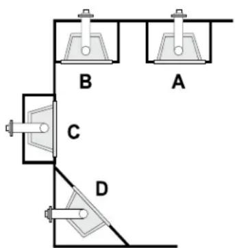
Diagram 1
A) Flat on wall
B) Flat on wall corner
C) Recessed into wall/alcove
D) Corner
- The GF1500L Direct Vent Gas Fireplace is approved for alcove installations, see "Clearances" section for details.
- We recommend that you plan your installation on paper, using exact measurements for clearances and floor protection, before actually installing this appliance. Have an authorized inspector, dealer, or installer review your plans before installation.

PACKAGING:
The unit and its contents are packaged to prevent damage during transport.
After unboxing, remove the plastic wrap then the screws that secure the unit to the pallet. Before commissioning of the unit, unwrap each log and set aside. Before installation of the logs, removal of the sheet metal cover that protects the burner is required.
Refer to subsequent instructions on proper set up and safety check before placing unit into commission.

Clearances
The clearances listed below are minimum distances unless otherwise stated.
A major cause of chimney-related fires is failure to maintain required clearances (air space) to combustible materials. It is of the greatest importance that this fireplace and flue system be installed only in accordance with these instructions.
| CAUTION | The top, back and sides of the fireplace are defined bystandoffs. The metal ends of the standoff may NOT berecessed into combustible construction. |
| WARNING | Fire hazard is an extreme riskIf these clearances (air space) to combustible materials are not adhered to. It is of greatest importance that this fireplace and flue system be installed only in accordance with these instructions. |
| Clearance: Dimension Measured From: | |
| A: Mantel Height (min.) | 254 mm Top of fireplace opening/hot air outlet |
| B: Sidewall (on one side) | 152 mm Side of fireplace opening/hot air outlet |
| C: Ceiling (room and/or alcove) | 1162 mm Top of fireplace opening/hot air outlet |
| D: Mantel Depth (max.) | 305 mm 730 mm above fireplace opening/hot air outlet |
| E: Alcove Width | 1524 mm Sidewall to sidewall (minimum) |
| F: Alcove Depth | 914 mm Front to back wall (maximum) |
| G: From Floor | 617 mm Top of fireplace opening/hot air outlet |
| Note: | O No hearth required |
| Flue Clearances to Combustibles | |
| Horizontal - Top 76mm | |
| Horizontal - Side 51mm | |
| Horizontal - Bottom 51mm | |
| Vertical 51mm | |


installation
Framing Dimensions
| Dimensions | Description GF1500 | |
| A Framing Height 945 mm combustible finish | ||
| A^1 | Framing Height -Steel Stud 846 mm non combustible steel stud | |
| B Framing Width 1394 mm | ||
| C Framing Depth 568 mm | ||
| D Minimum Height to Combustibles 1225 mm | ||
| E Corner Wall Depth 1460 mm | ||
| F Corner Fading Wall Width 2065 mm | ||
| G Vent Centerline Height | 1016 mm | |
| H* | Non-combustible facing height | *see non-combustible facing height in this manual |
| I | Gas Connection Opening Height | 38 mm |
| J | Gas Connection Height | 67 mm |
| K Gas Connection Inset | 44 mm | |
| L | Gas Connection Opening Width | 89 mm |
NOTES
- A minimum thickness of 12mm non combustible facing board compliant with AS1530-1 and AS1530-3 is required when using the non-combustible flush finishing option. A minimum thickness of 10mm-19mm combustible facing board and a 13 mm air gap is required when choosing the combustible flush finishing option.
- Do not place timber studs below those already in place. Steel studs must be added as shown when choosing the non combustible flush finishing option, and installed after unit is in place, prior to installation of non- combustible finishing.
- If raising the unit, the minimum framing height measurement (A) must be adhered to.
For example: unit raised 300mm then A+ 300mm = 1240 mm.
IMPORTANT
- This unit can be finished with combustible facing material of 10-19mm thickness or non combustible facing material a minimum of 12 mm thick.

Combustible flush finishing framing

Non-combustible flush finishing framing

natural_image
Technical line drawing of a structural frame with vertical supports and a horizontal beam, labeled 'D' (no text or symbols beyond the label)


Combustible Finishing Unit Assembly/ Finishing/ Mantel Clearances + Mantel Leg Clearances
Unit Assembly Prior To installation
The nailing strips must be correctly positioned and attached before unit is slid into position.
Nailing Strips-Combustible Finishing
The nailing strips come attached to the unit. There is one plate on each side and one on the top. The top and side nailing strips are secured to the framing.
IMPORTANT
- The framing depth measurement is noted with the nailing strips set as far forward on the firebox as possible. The nailing strips can be adjusted up to 38 mm to allow for varying thickness of non combustible material & wall finishes.

(DO NOT REMOVE NAILING STRIPS WHEN USING COMBUSTIBLE FINISHING)
Installing Access Panel
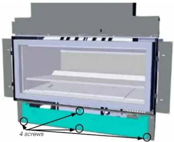
The unit is equipped with a removable access panel for pre-finish installation of optional components. This panel is located on the lower front face. Access to the gas connection is easier with the panel removed.
- Remove four screws to remove access panel.
- Install any optional components with access panel removed.
- To reinstall the access panel, line up the two upper tabs and secure with four screws.
NOTE
- The access panel is no longer usable/accessible once facing material is installed.
installation
Framing & Finishing (Combustible)
| Finished Material | ||
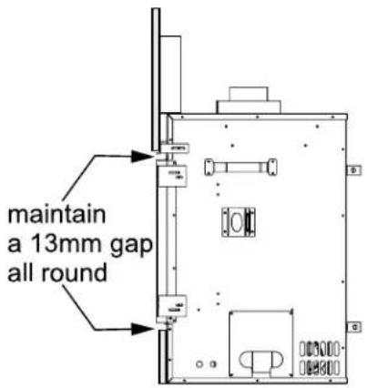
| 10mm-19mm thickness using combustible finishingNote: must maintain 13mm air gap all around(see diagrams below and on next page) | 1st slot |  |
NOTES
- *The finishing trim or one of the fascias must be used with combustible finishing.
- 10 mm to 19 mm combustible finishing can be used if the 13 mm air gap around the front facing of the unit is maintained. Finishing material cannot be thicker than 19 mm and must be flush with the front edge of the flange.
- The siding nailing strips are factory set at 10 mm. The top nailing strip is fixed during transit to the rear of the appliance.
- Do not place any reinforcement in front of the header and behind the finishing material.
- The nailing strip must be used. It is fixed during transit to the rear of the unit.
- Depending on the material used for finishing, the nailing strips must be set accordingly so that the finished material is always flush with the edge of the flange.
- If finishing with material that has a combined thickness greater than 19 mm, non combustible material must be used.
Combustible Requirements
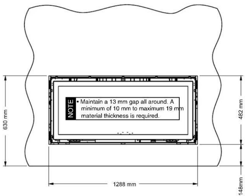
NOTES
- The appliance must be installed on a flat, solid, continuous surface. For example a wood, metal or concrete floor. In a raised (on the wall) application the appliance must be installed on a metal or wood panel extending the full width and depth of the appliance.
- Do not remove the standoffs located around the perimeter of this unit These act as a guide for placing the combustible material.
Clearances for Combustible Finishing with Mantel
Due to the extreme heat this fireplace emits, the mantel clearances are critical.
Combustible finishing and mantel clearances are shown in the diagram on the right. Finishing trim must be used with combustible finishing.
NOTES
• Maximum combustible finishing material thickness is 19 mm, measured from the front of the fireplace opening. If total finishing material is greater than 19 mm, non combustible material must be used.
- Use high quality paint on the mantel and facing, or the paint may discolour.
- Combustible mantel starts at 796 mm (618 mm + 178 mm) from the unit's base.
Important:

Combustible Mantel Leg Clearances
Mantel leg & combustible finishing clearances are shown in the diagram below.

installation
Non Combustible Flush Finishing - Unit Assembly/Finishing/Mantel Clearances + Mantel Leg Clearances
Remove top nailing strips & standoffs at side and underneath
- Remove the top nailing strip/standoff by removing 4 screws in locations shown in diagram to the right, then lift off and recycle.

natural_image
Technical line drawing of a mechanical housing or enclosure with internal components and directional arrows (no text or symbols)- Break off the 8 standoffs with a pair of pliers.

natural_image
Technical line drawing of a rectangular electronic device with mounting holes and internal components, showing no text or symbols.Remove 8 standoffs
Installation of Access Panel
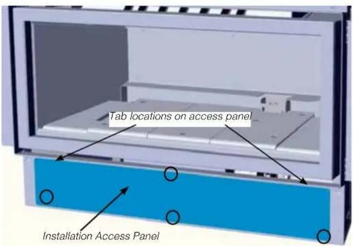
The unit is equipped with a removable access panel for pre-finish installation of optional components - this panel is located on the lower front face.
- Remove 4 screws to remove access panel.
- Easier access to gas connection with panel removed.
- Install any optional components with access panel removed.
- Reinstall access panel, line up 2 upper tabs and secure in place with 4 screws.
Note: Access panel is no longer usable/accessible once facing material installed.
Clearances For Non Combustible Flush Finishing with Mantel
Due to the extreme heat this fireplace emits, the mantel clearances are critical.
Combustible mantel clearances from top of front facing are shown in the diagram on the right.
NOTES
- For a flushed finish using non-combustible finishing, seven 13mm stand-off tabs around the fireplace opening must be broken off. The top nailing flange cannot be used and a non-combustible steel stud must be installed to support the non-combustible facing.
- Ensure the paint that is used on the mantel and the facing is high quality or the paint may discolour.

Non Combustible Mantel Leg Clearances
Mantel leg & Non-combustible finishing clearances as per diagram: (Flushed Finish)

installation
Flushed Finishing & Framing with Non Combustible Material
| Finished Material | * diagrams shown below are with top nailing strip removed. |
| 12mm | 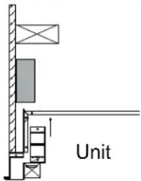 |
| 25mm | 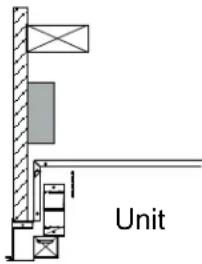 |
| 38mm |  |
NOTE
- For flush finishing, the top nailing strip must be removed and a non-combustible steel stud support added.
The seven fireplace opening standoffs which are located on this unit can be removed when non combustible material is installed flush with the unit. (see P. 13).
Non-combustible finishing material on the top and sides must also be used.
MINIMUM THICKNESS OF THE FINISH MATERIAL: 12MM
Non Combustible Requirements

NOTE
- The appliance must be installed on a flat, solid, continuous surface. For example a wood, metal or concrete floor. In a raised (on the wall) application the appliance must be installed on a metal or wood panel extending the full width and depth of the appliance.
Installing a TV / Artwork Flush with the Unit
Note: All wiring should stay free and clear of the vent system to avoid damage due to heat, if located directly in front of the vent system. Ensure wiring is secured without any sag.
Heat deflector must overhang front of TV by 51mm.
Follow mantel clearance chart for install height and heat deflector depth.
| A—Depth of TV & Mounting Bracket | B—Height From Base of Unit | C—Distance From Top of 13mm Air Gap |
| 127mm 981 mm 351 mm | ||
| 153mm 1006 mm 376 mm | ||
| 178mm 1029 mm 399 mm | ||
| 203mm 1052 mm 422 mm | ||
| 229mm 1077 mm 446 mm |


Note: The TV mounting bracket can not be secured directly to the appliance. It must be secured to framing. The TV depicted in the picture may need to be higher depending on the style of TV mounting bracket used. The mounting bracket shown is a simple single strip TV secured to framing.
installation
TV Recess with 45 Degree Elbow TV Recess with Vertical Venting


IMPORTANT
- The clearances noted are recommended only and not a guarantee of compliance with all TV manufacturers' maximum allowable operating temperatures.
- It is the responsibility of the user to check the TV installation instructions to ensure that the location of the TV in relation to the fireplace is suitable.
- Most television manufacturers instruct the user to not place the television above any heat source. Doing so may negatively affect the longevity of the television and may negate the warranty.
- If you do place a television above the fireplace, please be aware of the large amount of heat the fireplace generates. Regency in no way guarantees or takes responsibility for the suitability of the above installation for all homes, or any negative impacts from placing a TV above the fireplace, including damage to the TV.
Optional Framing Kit
- Construct the timber framing, ensure inside dimensions are 1095 mm H x 1394 mm W as shown below.
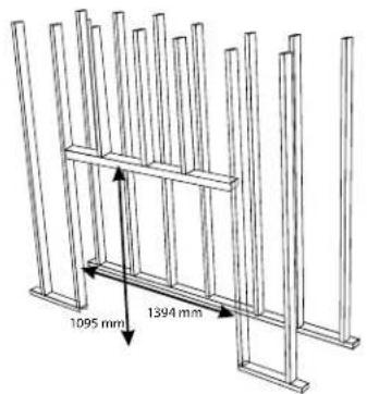
- Bend both side nailing strips from the side of the appliance until positioned as shown below. Determine the overall combined thickness of the non-combustible board + finished material being used. The nailing strips can be adjusted up to 38mm. Remove top nailing strip and recycle.

- Adjust the nailing strips by loosening 2 screws on each nailing strip - adjust and retighten screws.
NOTE: depending on the finishing material used.
- Attach both vertical studs (607-065) to the vertical timber studs and secure using 6 screws, as shown.
NOTE: Ensure the flat side of the steel stud is facing the timber framing.


- Secure horizontal steel header stud (606-067) with 2 screws per side as per diagram.

- Slide the unit into position. Hook up gas, flueing, electrical and conversion kit (if purchased) prior to installing the remaining steel studs.
- Secure the upper horizontal steel stud (606-067) as shown with 2 screws per side.
- Secure the top large horizontal stud (607-027) with 2 screws per side as shown. Bring finishing material to the edge of the top framing lip on large stud (607-027).
- Install the large lower stud (607-066) with 2 screws on each side.

Non Combustible Facing Installation
IMPORTANT
-
Prior to installation of non-combustible materials by others, check and inspect carefully for any hairline cracks and or damage to board. The non combustible board must be a minimum of 12mm thick and comply with AS1530-1 and AS1530-3. Material which is thinner may crack as a result due to the high temperatures this appliance emits.
• To avoid cracking the board-pre-drill holes prior to securing to unit/framing. -
Using screws for use with non-combustible boards-secure non-combustible material around unit, framing and top nailing strip every 150mm.
IMPORTANT
- To avoid cracking the board, pre-drill holes prior to securing the unit/framing.
- Wipe any debris/dust from the non-combustible material and dry wall.
- Prior to securing, it is mandatory to prime the facing and edges using a quality primer. This will ensure proper adhesion of the tape, filler and paint. Failure to follow this procedure will result in cracked seams.
- Tape the seams using a mesh type tape.
- Fill seams as normal. Avoid using filler which shrinks excessively. Filler must be cured as per manufacturer's recommendations.
- Prime wall for a second time for proper adhesion of paint.
- Paint walls using a high quality paint which will withstand the high temperatures being emitted from this appliance.
NOTES
- When applying 12 mm minimum non-combustible board to framework it is advisable to use the same 12mm minimum non-combustible board on the whole front face of the wall.
- When using a standard fascia cut out the clean edge trim opening plus a further 10 mm border.
- When using a 22 mm finishing trim cut out the clean edge trim opening plus a further 4mm border.
- When using painted 12 mm minimum non-combustible board as finished wall surface use 22 mm finishing trim.
- When using clean edge trim do not seal heater to finished wall material.
- The above will allow for possible expansion and contraction.
IMPORTANT
- Regency Fireplace Products are designed, produced, tested and certified to the highest industry standards. The finishing of the walls surrounding Regency is as critical as the installation itself. The temperatures around linear gas fireplaces are typically higher than would be acceptable for the combustible materials. Your Regency Fireplace is no exception to this rule. Therefore, the units are specified with non-combustible required materials to specific dimensions above and around the units. This is due to these areas reaching higher temperature levels than required/acceptable for a combustible material. To obtain the best, most durable finish around your fireplace, this calls for a high level of care and attention to the preparation and finish around this appliance, using only the highest quality materials, able to withstand the temperatures produced.
- By following the installation instructions in the manual exactly, you will increase your chances for a damage free finish.
- Every precaution is taken in providing the recommendations on preparation and finish, given the variation in paint quality, with temperature limits and workmanship applied to or used in any application surrounding the fireplace. This includes framing as well as finishing.
• Over time natural convection from any fireplace can cause discoloration in the area directly above the appliance. Lower quality paints, under prepared finishes, poor applications and any framing discrepancies or in the installation can cause this discoloration process to be expedited. - Discoloration is not the responsibility of Regency Fireplace Products, we believe careful attention to the recommendations provided here will be result in aesthetically pleasing result free of issues outlined above.
Framing & Finishing (Clean Finish Installations Only)
- Frame in the enclosure for the unit with framing material.

- The framed opening must be of non-combustible material.

- When constructing the framed opening, please ensure there is access to install the gas lines when the unit is installed.
- For exterior walls, insulate the enclosure to the same degree as the rest of the house, apply vapour barrier and drywall, as per local installation codes. (Do not insulate the fireplace Itself and/or the flueling. Clearances must be maintained as per this manual.)

- Failure to insulate and add vapor barriers to the inside of the exterior wall will result in operational and performance problems including, but not limited to: excessive condensation on glass doors, poor flame package, carbon, blue flames etc. These are not product related issues.
- The unit does not have to be completely enclosed in a chase. You must maintain clearances from the flue to combustible materials: See "Clearances" section. Combustible materials can be laid against the side and back standoffs and the appliance base.
- Non-combustible material (ie. tile, slate, etc) may be brought up to and overlap the unit (top and bottom) ensuring that the maximum thickness does not go beyond the 38mm as shown in the diagram below. The faceplate will not be able to be mounted if finished material is beyond 38mm.

installation
Exterior Flue Termination Locations

I = Mechanical air inlet M = Gas meter P = Electricity meter or fuse box T = Flue terminal Z = Fan-assisted appliance only
Shading indicates prohibited area for flue terminals
FIGURE 6.2 (in part): LOCATION OF FLUE TERMINALS OF BALANCED FLUE AS/NZ 5601, ROOM-SEALED, FAN ASSISTED, OR OUTDOOR APPLIANCE
Exterior Flue Termination Locations - Clearances
| Ref. Item | Minimum clearances (mm) | ||
| Natural Draught | Fan Assisted | ||
| a | Below eaves, balconies and other projections: | ||
| Appliances up to 50 MJ/h input 300 200 | |||
| Appliances up to 50 MJ/h input 500 300 | |||
| b From the ground, above a balcony or other surface* | 300 300 | ||
| c | From a return wall or external corner* 500 300 | ||
| d | From a gas meter (M) (see Note 5)(see Clause 5.11, 5.9 for vent terminal location of regulator)(see Table 6.7 for New Zealand requirements) | 1000 1000 | |
| e | From an electricity meter or fuse box (P)† (see Note 5) 500 500 | ||
| f | From a drain or soil pipe 150 75 | ||
| g | Horizontally from any building structure* or obstruction facing a terminal 500 500 | ||
| h | From any other flue terminal, cowl, or combustion air intake | 500 300 | |
| j | Horizontally from an openable window, door, non-mechanical air inlet, or any other opening into a building iwith the exception of sub-floor ventilation: | ||
| Appliances up to 150MJ/h input* | 500 300 | ||
| Appliances over 150MJ/h input up to 200 MJ/h input* | 1500 | 300 | |
| Appliances over 200MJ/h inputup to 250 MJ/h input** | 1500 | 500 | |
| Appliances over 250MJ/h input* | 1500 1500 | ||
| All fan-assisted flue appliances, in the direction of discharge | - | 1500 | |
| k | From a mechanical air inlet, including a spa blower | 1500 1000 | |
| n | Vertically below an openable window, non-mechanical air inlet, or any other opening into a building iwith the exception of sub-floor ventilation: | ||
| Space heaters up to 50MJ/h input | 150 150 | ||
| Other appliances up to 50 MJ/h input | 500 500 | ||
| Appliance over 50 MJ/h input and up to 150 MJ/h input | 1000 1000 | ||
| Appliances over 150 MJ/h input | 1500 1500 | ||
| * Unless appliance is certified for closer installation.† Prohibited area below electricity meter or fuse box extends to ground level.NOTES:1 Where dimension c, J or k cannot be achieved an equivalent horizontal distance measured diagonally from the nearest discharge point of the terminal to the opening may be deemed by the Technical Regulator to comply.2 See Clause 6. 9. 4 for restriction on the flue terminal under a covered area.3 See Figure J3 for clearances required from a flue terminal to a propane gas cylinder. A flue terminal is considered to be a source of ignition.4 For appliance not addressed above acceptance should be obtained from the Technical Regulator.5 Minimum clearance d and e also apply to any combustion air intake openings of appliances. | |||
installation
127 mm x 203 mm Rigid Pipe - Cross Reference Chart Only
Not all Rigid Pipe components are available directly from FPI.
| Description | SimpsonDirect Vent Prd ^ |
| 152 mm Pipe Length-Galvanized | 58DVA-06 |
| 152 mm Pipe Length-Black | 58DVA-06B |
| 229 mm Pipe Length-Galvanized | 58DVA-09 |
| 229 mm Pipe Length-Black | 58DVA-09B |
| 305 mm Pipe Length-Galvanized | 58DVA-12 |
| 305 mm Pipe Length-Black | 58DVA-12B |
| 457 mm Pipe Length-Galvanized | 58DVA-18 |
| 457 mm Pipe Length-Black | 58DVA-18B * |
| 610 mm Pipe Length-Galvanized | 58DVA-24 |
| 610 mm Pipe Length-Black | 58DVA-24B |
| 914 mm Pipe Length-Galvanized | 58DVA-36 |
| 914 mm Pipe Length-Black | 58DVA-36B |
| 1219 mm Pipe Length-Galvanized | 58DVA-48 |
| 1219 mm Pipe Length-Black | 58DVA-48B |
| 1524 mm Pipe Length-Galvanized | 58DVA-60 |
| 1524 mm Pipe Length-Black | 58DVA-60B * |
| Adjustable Length 76 mm-254 mm-Galvanized | N/A |
| Adjustable Length 76 mm-254 mm-Black | N/A |
| Adjustable Length 279 mm-356 mm -Galvanized | Disc. - See 58DV-08A |
| Adjustable Length 279 mm-356 mm-Black | Disc. - See 58DV-08B |
| Extension Pipe 432 mm-610 mm-Galvanized | Disc. - See 58DV-16A |
| Extension Pipe 432 mm-610 mm-Black | Disc. - See 58DV-16AB |
| Adjustable Length 216 mm-Galvanized | 58DVA-08A ^4 |
| Adjustable Length 216 mm-Black | 58DVA-08AB |
| Extension Pipe 406 mm-Galvanized | 58DVA-16A * |
| 45° Elbow-Galvanized 58DVA-E45 | |
| 45° Elbow-Black 58DVA-E45B | |
| 45° Elbow Swivel-Galvanized | Disc. - See 58DVA-E45 |
| 45° Elbow Swivel-Black | Disc.-See 58DVA-E45B |
| 90° Elbow-Galvanized 58DVA-E90 | |
| 90° Elbow-Black 58DVA-E90B | |
| 90° Elbow, Swivel-Galvanized | Disc. - See 46DVA-E45 |
| 90° Elbow, Swivel-Black | Disc. - See 46DVA-E45 |
| 90° Starter Elbow, Swivel-Galvanized | N/A |
| Adaptor* N/A | |
| Ceiling Support 58DVA-DC | |
| Cathedral Support Box 58DVA-CS | |
| Wall Support/Band 58DVA-WS | |
| Offset Support 58DVA-ES | ` |
| Wall Thimble-Black 58DVA-WT | |
| Wall Thimble Support/Ceiling Support 58DVA-DC | ` |
| Firestop Spacer 58DVA-FS | |
| Trim Plate-Black 58DAV-WFS | |
* Not available from Regency
| Description | SimpsonDirect Vent Pro® |
| Attic Insulation Shield 305 mm 58DVA-IS* | |
| Basic Horizontal Termination Kit (A) | N/A |
| Horizontal Termination Kit (B) | 58DVA-KHA |
| Vertical Termination Kit | 58DVA-VHA |
| High Wind Vertical Cap 58DVA-VCH | |
| High Wind Horizontal Cap N/A | |
| Horizontal Square Termination Cap N/A | |
| Vertical Termination Cap N/A | |
| Storm Collar 58DVA-SC |
| Adjustable Flashing Flat - 26.570 | 58DVA-F6 |
| Adjustable Flashing 26.570-451 | 58DVA-F12 |
| Vinyl Siding Standoff 58DVA-VSS | |
| Vinyl Siding Shield Plate N/A |
| Snorkel Termination 356 mm 58DVA-SNK14 |
| Snorkel Termination 914 mm 58DVA-SNK36 ^A |
| Restrictor Disk N/A | |
| Collinear Flex Connectors N/A |
* Not available from Regency
| FPI | |||
| 946-604/P | Simpson Direct Vent or Astro Cap -Vent Guard (Optional) | 946-623/P | AstroCap XL Horizontal Cap |
| 770-994 Rigid Pipe Adaptor (Must use with all rigid piping) | |||
| 946-625 | Vinyl Siding Standoff - AstroCap XL | ||
| Offset Pipe Selection: Use this table to determine offset pipe lengths. | ||||
| Pipe Length (L) | 127 mm x 203 mm venting |  | For specific instructions on venting components - visit the manufacturers website listed below. | |
| Run (X) | Rise (Y) | |||
| 0 mm | 144 mm | 389 mm | Simpson Direct Vent Pro: www.duravent.com | |
| 152 mm | 224 mm | 468 mm | ||
| 229 mm | 278 mm | 522 mm | ||
| 305 mm | 330 mm | 576 mm | ||
| 610 mm | 697 mm | 789 mm | Note: Horizontal runs of vent must be level, or have a 6 mm rise for every 305 mm of run towards the termination. Never allow the vent to run downward - this could cause high temperatures and may present a possible fire hazard. | |
| 914 mm | 757 mm | 1002 mm | ||
| 1219 mm | 972 mm | 1216 mm | ||
installation
Flue Restrictor Settings
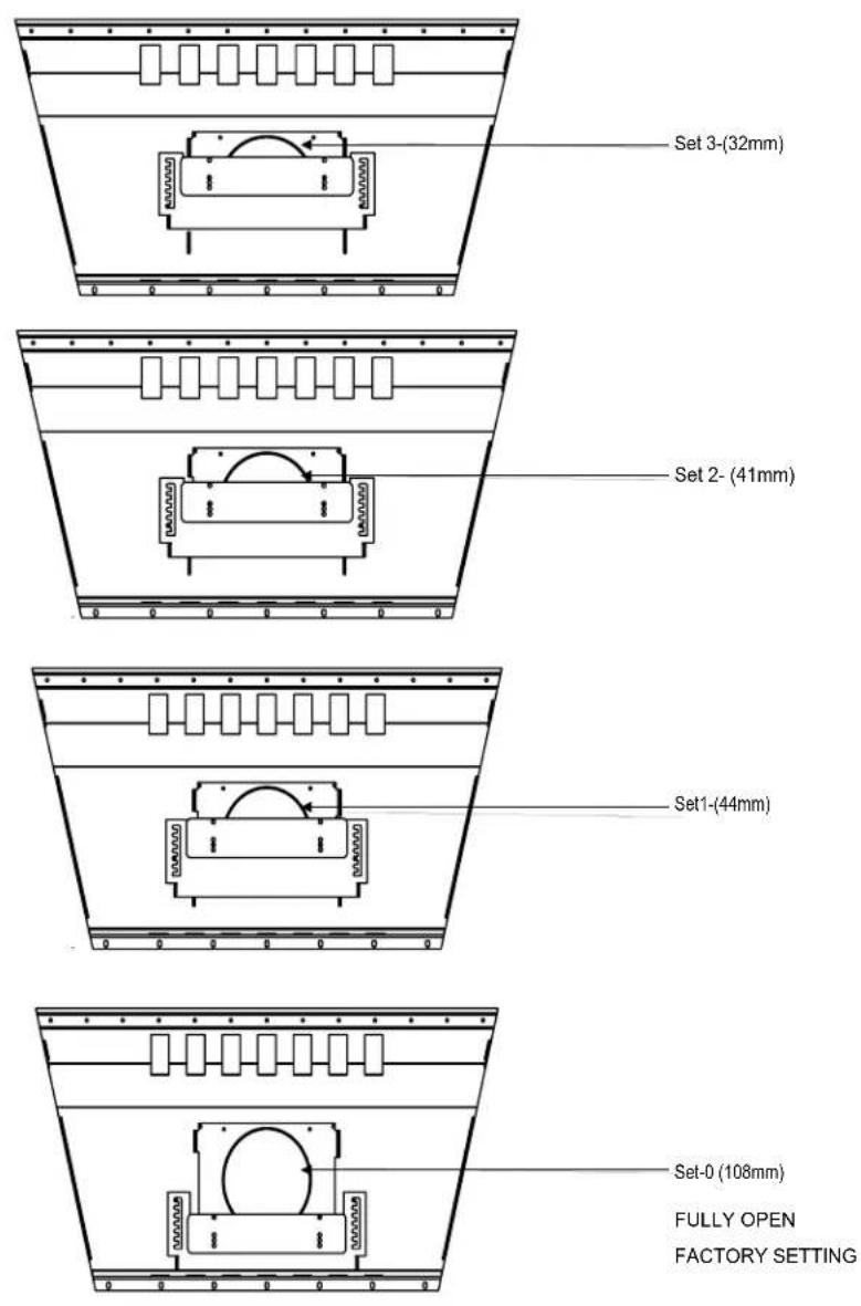
Flue restriction is required for certain venting installations, see the diagrams in the "Flueing Arrangements" section to determine if they are required for your installation.
The Flue Restrictor plate is located on the inside top of the firebox.
To set the flue restriction as indicated in the flueing arrangements diagrams, refer to the following instructions;
- Remove the glass door and inner panels - see instructions in this manual.
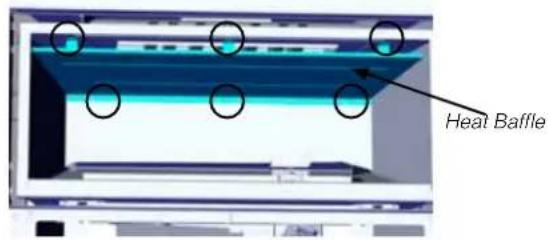
- Remove 6 screws (3 front - 3 back) to remove heat baffle to access restrictor plate.
- Remove the screws (circled in the image below) that hold the flue restrictor in place.
- Adjust the flue restrictor plate to the required flue restrictor position as per the diagrams shown below.
- Once the flue restrictor plate is in the required position, secure with screws.
Flueing Introduction
The GF1500L uses the "balanced flue" technology Co-Axial system. The inner liner vents products of combustion to the outside while the outer liner draws outside combustion air into the combustion chamber thereby eliminating the need to use heated room air for combustion and losing warm room air up the chimney.
Note: These flue pipes must not be connected to any other appliance.
The gas appliance and flue system must be vented directly to the outside of the building, and never be attached to a chimney serving a separate solid fuel or gas burning appliance. Each direct vent gas appliance must use it's own separate flue system. Common flue systems are prohibited.
Flueing Arrangement for Horizontal Terminations
The diagram shows all allowable combinations of vertical runs with horizontal terminations, using one 90° (two 45° elbows equal one 90° elbow).

- Must use optional rigid pipe adapter (Part# 770-994) when using Simpson Dura Vent Only.

other
| Section | Width (mm) | | ------- | ---------- | | Restrictor Set #0 Full Open | 1061 | | Restrictor Set #1 44 mm-Open | 44 | | Restrictor Set #2 41 mm-open | 41 |FLUE RESTRICTOR SETTING:
Flue restrictor factory set at Set 0.
Refer to the "Flue Restrictor Position" section for details on how to change the flue restrictor from the factory setting of Set 0 to Set 1 if required.
- Maintain clearances to combustibles as listed in "Clearances" section
• Horizontal flue must be supported every 0.9m - A flue guard should be used whenever the termination is lower than the specified minimum or as per local codes.
- Flex system can only be used up to 3m - otherwise rigid system must be used.
installation
Rigid Pipe Flueing Systems - Basic Horizontal & Vertical Terminations
Rigid Pipe Flue Systems offer a complete line of component parts for installation of both horizontal and vertical installations. Many items are offered in decorative black, as well as galvanized finish.
The minimum components required for a basic Horizontal Termination are:
1 AstroCap XL Termination Cap
1 90o Elbow
1 Rigid Pipe Adaptor (Dura Vent Only)
1 Wall Thimble
1 Length of rigid pipe to suit wall thickness
The minimum components required for a basic Vertical Termination are:
1 Vertical Termination Cap
1 Rigid Pipe Adaptor (Dura Vent Only)
1 Lengths of pipe to adequately penetrate roof
1 Flashing (As required per AS/NZS 5601-2013, to be supplied by installer)
Wall thickness is measured from the back standoffs to the inside mounting surface of termination cap. For siding other than vinyl furring strips may be used, instead of the vinyl siding standoff, to create a level surface to mount the vent terminal. The Terminal must not be recessed into wall cladding. Measure the wall thickness including wall cladding.
• Do not combine flueing components from different venting systems.
- Exception: However, use of the the AstroCap XLTM is acceptable with all systems.
When using Rigid Flue other than Simpson Dura-Vent, 3 screws must be used to secure rigid pipe to adaptor.

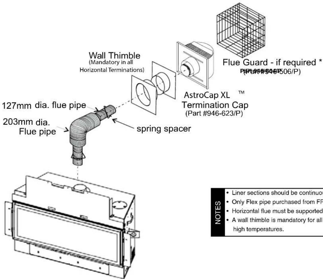
Flueing Arrangements - Horizontal Termination (Flex) - Regency® Direct Vent System
These flueing systems, in combination with GF1500L, have been tested and listed as a Direct Vent system by AGA. The location of the termination cap must conform to the requirements in the Flue Terminal Locations diagram from the "Exterior Flue Termination Locations" section.
FPI Direct Vent (Flex) System Termination Kits Include all the parts needed to install the GF1500L using a flexible vent.
| FPI Kit # Length Contains: | |
| #946-615 1.2 m | 1) 203mm flexible liner (Kit length)2) 127mm flexible liner (Kit length)3) spring spacers4) thimble5) AstroCap termination cap6) screws7) tube of Mill Pac8) plated screws9) S.S. screws #8 x 38mm drill point |
| #946-618 1.8 m | |
| #946-616 3 m | |
installation
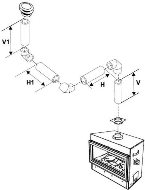
Horizontal Venting with Two 90 Elbows
One 90° elbow = Two 45 elbows.
| Option V | H + H1 | With these options, maximum total pipe length is 9.1 m with maximum 2.4 m total horizontal.Please note minimum 0.3 m between 90° elbows is required. | |
| A) 0.3 | m Min. 0.9 m | Max. | |
| B) 0.6 | m Min. 1.2 m | Max. | |
| C) 0.9 | m Min. 1.5 m | Max. | |
| D) 1.2 | m Min. 1.8 m | Max. | |
| E) 1.5 | m Min. 2.1 m | Max. | |
| F) 1.8 | m Min. 2.4 m | Max. | |
| Restrictor Set 0 (108 mm) Factory Setting | |||

Horizontal Venting with Three 90° Elbows

One 90° elbow = Two 45° elbows.
| Option V | H V + V1 H + | H1 | With these options, max. total pipe length is 9.1 m with max. 2.7 m total horizontal.Please note min.0.3 m between 90°elbows is required. | ||
| A) | 0 Min. | 0.3 m Max. | 0.3 m Min. | 0.6 m Max. | |
| B) | 0.3 m Min. | 0.6 m Max. | 0.9 m Min. | 0.9 m Max. | |
| C) | 0.6 m Min. | 0.6 mMax. | 1.5 m Min. | 1.2 m Max. | |
| D) | 0.9 m Min. | 0.6 m Max. | 2.1 m Min. | 1.5 m Max. | |
| E) | 1.2 m Min. | 0.9 m Max. | 2.7 m Min. | 1.8 m Max. | |
| F) | 1.5 m Min. | 1.2 m Max. | 3.0 m Min. | 2.1 m Max. | |
| G) | 1.8 m Min. | 1.5 m Max. | 3.3 m Min. | 2.4 m Max. | |
| H) | 2.1 m Min. | 1.8 m Max. | 3.6 m Min. | 2.7 m Max. | |
| Restrictor Set 0 (108 mm) Factory Setting | |||||
installation
Unit Installation with Horizontal Termination (Rigid Flue Systems)
A top clearance of 76mm and side & bottom clearance of 51mm must be maintained; except when passing through a wall, ceiling, or at the termination where the use of a firestop or wall thimble reduces the required clearance to 38mm. We recommend framing a 279mm x 279mm (inside dimensions) hole to give structural rigidity for mounting the termination.
Install the flue system according to the manufacturer's instructions included with the components.
- Set the unit in its desired location. Check to determine if wall studs or roof rafters are in the way when the flueing system is attached. If this is the case, you may want to adjust the location of the unit. Rough in the gas preferably on the right side of the unit.
- Simpson Dura-Vent Flue pipe and fittings are designed with special twist-lock connections to connect the venting system to the appliance flue outlet. A twist-lock appliance adaptor is required.

If using Flomet Rigid Flue System (Part No: 946-686), no Twist-lock appliance adaptor is required.
- In conjunction with the Simpson Direct Vent Pro system, install the adaptor after the unit is set in its desired location. Put a bead of Mill Pac inside the outer section of the adapter and a bead of Mill Pac on the inner collar. Slip the adapter over the existing inner and outer flue collar. Fasten to the outer collar only with the 3 supplied screws (drilling pilot holes will make this easier).
- Level the fireplace and fasten it to the framing using nails or screws through the top and side nailing strips.
- Assemble the desired combination of pipe and elbows to the appliance flue outlets and secure.

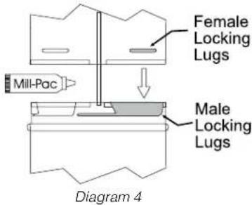
For best results and optimum performance with each approved flueing system apply "Mill-Pac" sealant to every inner pipe connection. Failure to do so may result in drafting or performance issues not covered under warranty.
"THIS UNIT MUST ALWAYS TERMINATE / FLUE DIRECTLY TO THE OUTDOORS."

NOT INTENDED FOR FIREPLACE INSERT.

Horizontal runs of flue must be supported every 0.9 metre. Wall straps are available for this purpose.
- Mark the wall for a 279mm x 279mm square hole. The center of the square hole should line up with the center-line of the horizontal pipe. Cut and frame the 279mm square hole in the exterior wall where the flue will be terminated. See diagram 2 for center line requirements.
If the wall being penetrated is constructed of non-combustible material, i.e. masonry block or concrete, an 203mm diameter hole is acceptable.
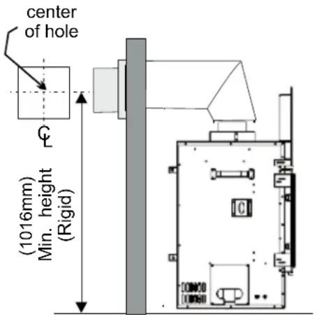
Diagram 2
NOTES
- The horizontal run of flue must be level, or have a 6mm rise for every 305mm of run towards the termination. Never allow the flue to run downward. This could cause high temperatures and may present the possibility of a fire.
-
The location of the horizontal flue termination on an exterior wall must meet all local and national building codes, and must not be blocked or obstructed. See "Exterior Flue Termination Locations" section for more details.
-
Ensure that the pipe clearances to combustible materials are maintained (Diagram 3). Install the termination cap.
The four wood screws provided should be replaced with appropriate fasteners for stucco, brick, concrete, or other types of sidings.

Diagram 3
- Before connecting the horizontal run of flue pipe to the vent termination, slide the Wall Thimble over the vent pipe. The wall thimble is required for all horizontal terminations.
- Slide the appliance and flue assembly towards the wall carefully inserting the flue pipe into the flue cap assembly. It is important that the flue pipe extends into the flue cap sufficient distance so as to result in a minimum pipe overlap of 32mm. Secure the connection between the flue pipe and the flue cap.
- Install wall thimble in the center of the 279 mm square and attach with wood screws (diagram 4).

Diagram 4
Unit Installation With Horizontal Termination Flex System
NOTE
- A top clearance of 76mm and side & bottom clearance of 51mm must be maintained; except when passing through a wall, ceiling, or at the termination where the use of a wall thimble reduces the required clearance to 38mm. We recommend framing a 279mm x 279mm (inside dimensions) hole to give structural rigidity for mounting the termination.
- Locate the unit in the framing, rough in the gas (preferably on the right side of the unit). Locate the centerline of the termination and mark wall accordingly. Cut an 279mm hole in the wall (inside dimension).
- Level the fireplace and fasten it to the framing using nails or screws through the nailing strips.
- Assemble the flue assembly by applying Mill Pac to the 127mm inner collar of the termination and slipping the 127mm liner over it at least 35mm. Fasten with the 3 screws (drilling pilot holes will make this easier). Apply Mill Pac or high temperature silicone to the 203mm flex pipe and slip it over the outer collar of the vent terminal at least 35mm and fasten with the 3 screws.
NOTE
- Horizontal sections must be supported at intervals not exceeding 0.9 meter. (Flame picture and performance will be affected by sags in the liner).
- Separate the 2 halves of the wall thimble and securely fasten the one with the tabs to the outside wall making sure that the tabs are on top and bottom. Fasten the other thimble half to the inside wall. The thimble halves slip inside each other and can be adjusted for 51 x 102mm x 51mm x 152mm walls.
- Slip the assembled liner and termination assembly through the thimble making sure the termination cap faces up (there are markings on the cap that show which way is up). This will position the termination cap with proper down slope for draining water. Fasten the cap to the outer wall with the 4 supplied screws.
- Pull the centre 127mm liner and outer 203mm liner out enough to slip over the flue collars of the fireplace. (You may wish to cut the liner shorter to make it more workable.) Do not bend liner more than 90°. The liners must slip over the collars a minimum of 35mm.
- Apply Mill Pac over the fireplace inner collar and slip the 127mm liner down over it and attach with 3 supplied screws.
- Do the same with the 203mm liner.
- Apply a bead of silicone between the thimble and termination and around the outer edge of the terminal at the wall in order to keep the water out.
IMPORTANT
- Do not locate termination hood where excessive snow or ice buildup may occur. Be sure to check flue termination area after snow falls, and clear to prevent accidental blockage of flueing system. When using snow blowers, make sure snow is not directed towards vent termination area.
ASTROCAP XL DIMENSIONS (946-623/P)

"THIS UNIT MUST ALWAYS TERMINATE / FLUE DIRECTLY TO THE OUTDOORS."

Flueing Arrangement for Vertical Terminations - Vertical Flue with Two 90 Elbows (1 - 90° = 2 - 45°)
The shaded area in the diagram shows all allowable combinations of straight vertical and offset to vertical terminations, using two 45° bends, with Rigid/Flex Pipe Flueing Systems.
- Flue must be supported at offsets.
- Maintain clearances to combustibles as listed in the "Clearances" section.
• Horizontal vent must be supported every 1M. - Must use optional rigid pipe adaptor (Part# 770-994) when using rigid pipe flue systems (Dura Vent Only).
- Refer to the "Flue Restrictor Position" section for details on how to change the flue restrictor from the factory setting of Set 0 to Set 1, Set 2 or Set 3 if required.
- Vertical flue must terminate a minimum of 600m to the underside of the cowl from the nearest part of the roof, as per AS/NZS 5601.
"THIS UNIT MUST ALWAYS TERMINATE / FLUE DIRECTLY TO THE OUTDOORS."

other
| Vertical Height (Metres) | Maximum (m) | | ------------------------ | ----------- | | 0 | 6.7 | | 1.5 | 6.7 | | 2 | 6.7 | | 3.5 | 6.7 | | 4 | 6.7 | | 5.5 | 6.7 | | 7 | 6.7 | | 7.5 | 6.7 |installation
Vertical Venting with Three 90 Elbows
One 90° elbow = Two 45° elbows.
| Option V H + H1 V + V1 | With these options, max. total pipe length is 9.1 m with max. 2.4 m total horizontal.Please note min.0.3 m between 90°elbows is required. | |||
| A) 0 Min. 0.6 m Max. 0.6 m Min. | ||||
| B) 0.3 m Min. 0.6 m Max. 0.9 m Min. | ||||
| C) 0.6 m Min. 0.9 m Max. 1.2 m Min. | ||||
| D) 0.9 m Min. 1.2 m Max 1.8 m Min. | ||||
| E) 1.2 m Min. 1.5 m Max 2.1 m Min. | ||||
| F) 1.5 m Min. 1.8 m Max 2.4 m Min. | ||||
| G) 1.8 m Min. 2.1 m Max 2.7 m Min. | ||||
| H) 2.1 m Min. 2.4 m Max 3.0 m Min. | ||||
| NG & U LPG-Restrictor Set 0 (108 mm) Factory SettingPropane - Restrictor Set 1 (44 mm) | ||||

Direct Flue Zero Clearance Top Exit Vertical Flue Kit Installation Instructions
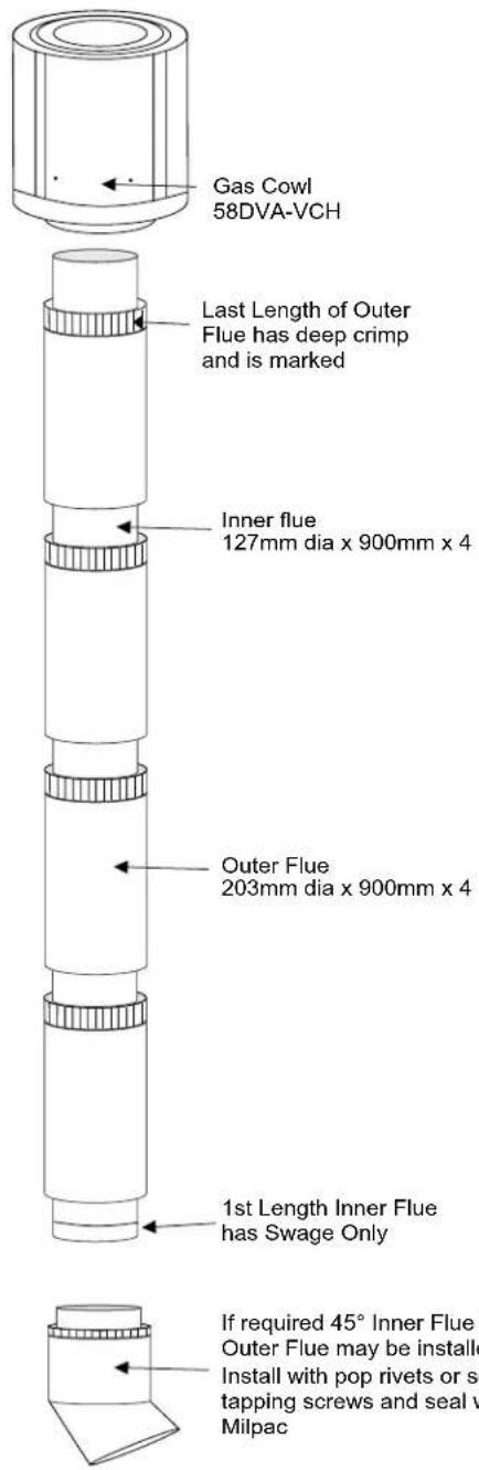
This flue kit has been manufactured for use with GF1500L and to be installed in accordance with AS/NZS 5601. To ensure safety and correct unit operation this flue kit must be installed as outlined in these instructions. Heater and flue clearances from combustible materials must be in accordance with these instructions and AS/NZS 5601.
- Locate the heater in its proposed position and mark the point for penetration directly above the centre of the heater flue outlet. Check the heater location allows the outer flue to clear all structural timber and combustible surfaces by 40mm minimum.
- If the enclosure consists of a ceiling – cut a 303mm square hole (minimum) for the flue to penetrate, cut hole through roofing material and prepare flashing for termination.
- Starting at the heater, install first length of inner pipe, using Mill-Pac sealant and self-tapping screws (or rivets). Note – first length of inner pipe has a Swage only.
- Continue assembling flue pipes inner and outer, ensuring each inner join is sealed using Mill-Pac sealant and self-tapping screws (or rivets). Outer flue pipe installs crimped end up and must be sealed and fixed together also.
- If required, fix outer flue in the ceiling space using non-combustible bracing to stop movement. On penetration of roof, fit an appropriate flashing or weather seal to suit the roofing material, ensure all joints outside are sealed with appropriate sealer.
- Fit approved gas cowl ensuring inner and outer flue pipes are sealed.
- Start heater and run for at least 15 minutes to check flue seal. If operational issues are noted, check flue again to ensure proper seal of inner pipe.
SUPPLIED MIII-Pac SEALANT MUST BE USED OR WARRANTY WILL BE VOID - IF REQUIRED, MORE SEALANT CAN BE PURCHASED USING PART NUMBER 948-128
45° bends (if required) part number 946-688 – Note, if bends are used at the start of flue run, a deeper crimp may be required at the unit for inner pipe fitment. Can be crimped on site and sealed with Mill-Pac sealant and self-tapping screws (or rivets).
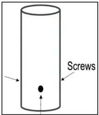
NOTES
- Use a minimum of 3 screws equidistant secure every inner flue pipe joint as well as Mil-Pac sealant.
- It is the installers responsibility to ensure the installation complies with AS/NZS 5601 and all local and building codes.

natural_image
Close-up of a metallic cylindrical object with a textured background (no visible text or symbols)Mil-Pac SEALANT INNER FLUE
installation
Unit Installation with Vertical Termination (Rigid Systems)
NOTE
- A clearance of 50mm must be maintained. We recommend framing a 279mm x 279mm (inside dimensions) hole to give structural rigidity for mounting the termination.
-
Do not pack air spaces with insulation. Check "Flueing Arrangement - Vertical Termination" section for the maximum vertical rise of the flueing system and the maximum horizontal offset limitations.
-
Set the gas appliance in its desired location. Drop a plumb bob down from the ceiling to the position of the appliance flue exit, and mark the location where the flue will penetrate the ceiling. Drill a small hole at his point. Next, drop a plumb bob from the roof to the hole previously drilled in the ceiling, and mark the spot where the flue will penetrate the roof. Determine if ceiling joists, roof rafters or other framing will obstruct the flueing system. You may wish to relocate the appliance or to offset, as shown in Diagram
2 to avoid cutting load bearing members.

natural_image
Technical line drawing of a vertical cylindrical structure mounted on a base, with no visible text or symbols.Diagram 1

Diagram 2
- Cut a hole large enough to allow for proper clearances and or large enough for heat to escape cavity.
- Assemble the desired lengths of pipe and elbows. Ensure that all pipes and elbow connections are in the fully twist-locked position and sealed.

Diagram 3
NOTE
- For best results and optimum performance with each approved flueing system, "Mill-Pac" sealant to every inner pipe connection. Failure to do so may result in drafting or performance issues not covered under warranty.
- Cut a hole in the roof centered on the small drilled hole placed in the roof in Step 2. The hole should be of sufficient size to meet the minimum requirements for clearance to combustibles of 50mm.
- Continue to assemble pipe lengths.
NOTE - If an offset is necessary in the roof space to avoid obstructions, it is important to support the flue pipe every 0.9 meter, to avoid excessive stress on the elbows, and possible separation. Metal Wall straps can be used (diagram 2). Do not combine flueing components from other manufacturers.
Galvanized pipe is desirable above the roofline due to its higher corrosion resistance. Continue to add pipe sections through the flashing until the height of the flue cap meets the minimum height requirements specified in local codes. Note that for steep roof pitches, the vertical height must be increased.
A poor draft, or down drafting can result from high wind conditions near big trees or adjoining roof lines, in these cases, increasing the flue height may solve the problem. Maximum height is 6.7 meters.
"THIS UNIT MUST ALWAYS TERMINATE / FLUE DIRECTLY TO THE OUTDOORS."

Diagram 5
-
Penetrate roof and secure flashing (supplied by installer)
-
Install the vertical termination cap.
NOTE
- Any closets or storage spaces, which the flue passes through must be enclosed.
| Roof Pitch Minimum | Flue Height |
| Meters | |
| flat to 30.26° | 0.61 |
| over 30.26° to 33.69° | 0.61 |
| over 33.69° to 36.37° | 0.61 |
| over 36.37° to 39.81° | 0.76 |
| over 39.81° to 42.51° | 0.99 |
| over 42.51° to 45.00° | 1.22 |
| over 45.00° to 49.40° | 1.52 |
| over 49.40° to 53.13° | 1.83 |
| over 53.13° to 56.31° | 2.13 |
| over 56.31° to 59.04° | 2.29 |
| over 59.04° to 60.26° | 2.44 |
Vertical Termination - 127 mmx 203 mm Flueing - Vertical Flex Kit (Part 946-772)
Must choose 1 of the following:
Part #
Description
946-772
Vertical Flex Kit 127 mm x 203 mm x 6.1 m
NOTE
The roof flashing is not included with this kit and must be purchased separately.
Vertical flex must still abide by the limitations set in the vertical venting charts.
- Maintain the 38 mm clearance (air space) to combustibles when passing through ceilings, walls, floors, enclosures, attic rafters or other nearby combustibles. Do not pack air spaces with insulation. Check venting sections for the maximum vertical rise of the venting system and the maximum horizontal offset limitations.
Ensure that you maintain clearances around enclosures, walls, below or above floors, floor joists, etc. Each appliance has different clearance requirements (top, sides, bottom). See specific appliance manual for details.
- Set the appliance in its desired position. Drop a plumb bob down from the ceiling/floor joist to the position of the appliance flue exit and mark the location where the vent will penetrate the ceiling. Drill a small hole at this point. Next drop a plumb bob from the roof to the hole previously drilled at the ceiling level and mark the spot where the vent will penetrate the roof.
- Cut a hole in the roof centered on the small hole placed in the roof in the previous steps. The hole should be a minimum of 279 mm. The hole may be round and or square.
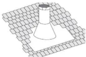
- Slip the flashing under the shingles and line up flashing so it is centered to the hole (shingles should overlap half of the flashing) as per Diagram 1.
natural_image
3D diagram of a conical funnel placed on a grid-patterned base (no text or symbols)Diagram 1 The upper half of the flashing is installed under the roofing material and not nailed down until the chimney is installed. This allows for small adjustments.
Diagram 1
- A ceiling firestop/firestop spacer must be installed when passing through each floor or ceiling level. To install the ceiling firestop/firestop spacer in a flat ceiling or floor joist cut a 279 mm square hole. Frame the hole as show in Diagram 2 and install the ceiling firestop. Slide the top attic insulation spacer onto the top of the attic insulation shield/firestop - See Diagram 2a. Secure with 4 screws/nails. If more than one is required, these can be purchased separately.
NOTE
The ceiling firestop/firestop spacer may be cut down to size if this shield is too high for the application.

Greenfire® GF1500L-2 Gas Fireplace

- Determine the overall height of the chimney from the top of the appliance to the underside of the vent. If required cut the flexible inner and outer pipe to the desired length up to a maximum of 6.1 m.
- Put a bead of Mill-Pac around the 127 mm collar on the appliance and slide the inner flex pipe over the inner collar of the appliance and secure with a minimum of 3 screws.
- Install 127 mm spacers around 127 mm flex.
- Repeat Step 7 to install the outer pipe to the outer collar of the appliance.
NOTE
- If an offset is necessary in the attic or floor joists it is important to support the vent pipe every 914 mm to avoid excessive stress and sagging of the vent pipe. Wall straps are provided (3 in total) for this purpose. All round/plumbers strapping may also be used if further supports are required.
- Attach the rigid pipe section to the adaptor by using MillPac on the inner/ outer pipe. Use 3 screws to secure outer pipe.
- Secure inner flex pipe to pipe adaptor using Mill-Pac over the adaptor. Slide the inner pipe over the flex to rigid adaptor and secure with 3 screws.
- Repeat Step 11 to secure outer flex.
installation
- Slide the finished length up towards the flashing ensuring the length of pipe is a minimum of 0.6 m measured from the top of the roof. Level the chimney and secure using the roof support provided with kit to bottom side of the roof as shown using a minimum of 2 screws per side- see Diagram 3b. See Diagram 4 for roof pitch and height requirements. See Diagram 3a for securing method if 0.6 m is insufficient and additional lengths are required, this may be purchased separately. See Simpson Duravent components list in the instruction manual for part numbers.

Diagram 3

Diagram 3a
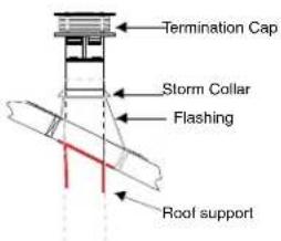
Diagram 3b
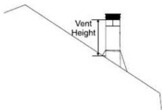
Diagram 4
| Roof Pitch | Minimum Flue Height |
| Meters | |
| flat to 30.26° | 0.61 |
| over 30.26° to 33.69° | 0.61 |
| over 33.69° to 36.37° | 0.61 |
| over 36.37° to 39.81° | 0.76 |
| over 39.81° to 42.51° | 0.99 |
| over 42.51° to 45.00° | 1.22 |
| over 45.00° to 49.40° | 1.52 |
| over 49.40° to 53.13° | 1.83 |
| over 53.13° to 56.31° | 2.13 |
| over 56.31° to 59.04° | 2.29 |
| over 59.04° to 60.26° | 2.44 |
- Put a bead of caulking on the exterior between the outer pipe and flashing to prevent water from penetrating the chimney system.
- Slide storm collar over pipe length until it reaches the flashing.
- Install termination cap by twist locking it.
- Secure the flashing to the roof using screws.
NOTE
- Any closets or storage spaces that the vent passes through must be enclosed.
Vertical Flue Extension Kit (Approved) (Part # 946-769)
Used in conjunction with the 946-772 Vertical Flex Kit for vertical installations.
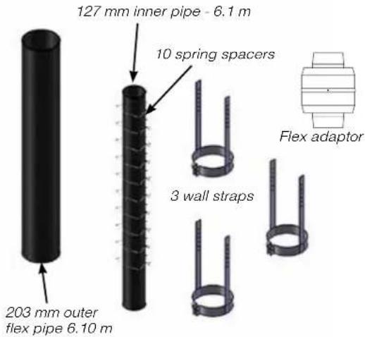
- Stretch out both inner 127 mm and outer 203 mm pipe up to a maximum of 6.1 m.

The inner and outer pipes may be cut if only a short length is required.
- Install spring spacers around 127 mm inner pipe as shown. Slide outer flex pipe over and all the way down the 127 mm pipe.
- Apply a bead of Mill Pac around the perimeter of the 127 mm inner collar of the flex adapter and slip the 127 mm inner flex pipe from the Vertical termination kit over the flex adapter ensuring that the inner flex pipe overlaps the collar by at least 35 mm. Fasten with 3 screws.
- Apply a bead of Mill Pac around the perimeter of the 203 mm outer collar of the flue adapter and slip it over the 203 mm outer flex pipe from the vertical termination kit ensuring that the outer flex pipe overlaps the collar by at least 35 mm. Fasten with the 3 screws.
- Repeat steps to secure the other end of the flex adapter using the flex kit.
- See vertical vent installation instructions for installation of the complete vent system.

If an offset is necessary in the attic or floor joists it is important to support the vent pipe every 0.91 m to avoid excessive stress and sagging of the vent pipe. Wall straps are provided (3 in total) for this purpose.
All round/plumbers strapping may also be used if further supports are required.
Ceiling Firestop / Firestop Spacer (Part 946-770)
Used in conjunction with the 946-772 Vertical Flex Kit and 946-769 Vertical Flex Extension Kit.
A ceiling firestop/firestop spacer must be installed when passing through each floor or ceiling level.
Steps to install the ceiling firestop/firestop spacer in a flat ceiling or floor joist:
- Cut a 279 mm square hole.
- Frame the hole as show in Diagram 1.
- Install the ceiling firestop.
- Slide the top attic insulation spacer onto the top of the attic insulation shield/firestop - See Diagram 1a.
- Secure with 4 screws/nails.
Firestops can be purchased separately if more than one is required.

The ceiling firestop/firestop spacer may be cut own to size if it is too high for the application.

Diagram 1a
installation
| GF1500LNG-2 SYSTEM DATA | |
| Min. Supply Pressure | 1.13 kPa |
| Low Setting Man. Pressure | 0.4 kPa |
| Max. Manifold Pressure | 0.87 kPa |
| Injector Size #29 DMS | (3.40 mm) |
| Minimum Input 36.9 MJ/h | |
| Maximum Input 50 MJ/h | |
| GF1500LLP-2 SYSTEM DATA | |
| Min. Supply Pressure | 2.75 kPa |
| Low Setting Man. Pressure | 1.6 kPa |
| Max. Manifold Pressure | 2.49 kPa |
| Injector Size | #47 DMS (1.99 mm) |
| Minimum Input 37.9 MJ/h | |
| Maximum Input | 49 MJ/h |
| GF1500LULPG-2 SYSTEM DATA | |
| Min. Supply Pressure | 2.75 kPa |
| Low Setting Man. Pressure | 1.6 kPa |
| Max. Manifold Pressure | 2.49 kPa |
| Injector Size | #49 DMS (1.85 mm) |
| Minimum Input 33.7 MJ/h | |
| Maximum Input | 44 MJ/h |
| Installer Notice:These instructions must be left with the appliance. |
High Elevation
This unit is approved for altitude 0 to 1372m.
Gas Line Installation
Since some municipalities have additional local codes it is always best to consult with your local authorities.
When using copper or flex connectors use only approved fittings. Always provide a union so that gas lines can be easily disconnected for servicing. Flare nuts for copper lines and flex connectors are usually considered to meet this requirement.
| NOTE | A approved shutoff valve should be supplied in or near the unit (or as per local codes) for ease of servicing this appliance. Access is required to the flex connection where joined to copper. |
Pilot Adjustment
Periodically check the pilot flames. Correct flame pattern has two strong blue flames: 1 flowing around the flame sensor and 1 flowing across the burner (it does not have to be touching the burner).


Incorrect flame pattern will have small, probably yellow flames, not coming into proper contact with the rear burner or flame sensor.
Gas Pipe Pressure Testing
The appliance must be isolated from the gas supply piping system by closing its individual manual shut-off valve during any pressure testing of the gas supply piping system at test pressures equal to or less than 3.45 kPa. Disconnect piping from valve at pressures over 3.45kPa.
The manifold pressure is controlled by a regulator built into the gas control, and should be checked at the pressure test point.

- Make sure the unit is in the "OFF" position.
- Loosen the "IN" and/or "OUT" pressure tap(s), turning counterclockwise with a suitable wide flat screwdriver.
- Attach manometer to "IN" and/or "OUT" pressure tap(s) using a suitable ID hose.
- Turn the unit on with the remote or manual switch
- The pressure check should be carried out with the unit burning and the setting should be within the limits specified on the safety label.
All the adjustments must be carried out in the following order:
a. Remove the modulator plastic cap (A) using needle nose pliers.
b. Maximum pressure: Turn the unit ON to its highest input rating. Screw in the nut (B) to increase the outlet pressure and screw it out to decrease it. Use a 10 mm wrench.
NOTES
- Do not screw in nut too far. If no pressure increases after two full terms, place manometer on inlet test point on gas valve and check flowing inlet pressure.
• The outlet pressure must be set to maximum 2.49 kPa for both Propane/ULPG and 0.87 kPa for NG.
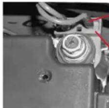
c. Minimum pressure: Remove one of the cables connected to the electric modulator. While holding thenut (B) with a wrench, screw in the screw (C) to increase the pressure and screw it out to decrease it. Use a screwdriver 6x1 blade.
natural_image
Close-up of a mechanical component with a threaded bolt and wiring (no visible text or symbols)Cable
Electric Modulator
d. After carrying out all adjustments, block the settingscrews with paint, taking care not to obstruct the breather orifice of the pressure.
e. Put the plastic modulator cap back.

• To ensure the correct operation of the modulator it is necessary that the plastic cap (A) is returned to its original location.

• The outlet pressure must be set to minimum 1.6 kPa. for both Propane/ULPG and 0.4 kPa for NG
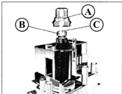
- Turn on gas supply and plug in power cord.
- At the end of all setting and adjustment operations, check electrical installation and gas leaks.
- Check operation of flame control.
- Check for proper flame appearance and glow on logs.
- When finished reading manometer, turn off the unit, disconnect the hose and tighten the screw (clockwise) with a suitable flat screwdriver.
NOTE
Screw should be snug, but do not over tighten.
Wiring Diagram (NG Only)
WARNING
- Disconnect power supply to unit prior to working on electrical components.
- Ensure that the wires do not touch any hot surfaces and are away from sharp edges.
- Label all wires prior to disconnection when servicing controls. Wiring errors can cause improper and dangerous operation.

920-367
845 S.I.T. Valve Description
1) On-Off Solenoid Valve EV1
2) On-Off Solenoid Valve EV2
3) Inlet Pressure Test Point
4) Outlet Pressure Test Point
5) Connection for Pressure Regulator/Combustion Chamber Compensation
6) Pressure Regulator for Minimum and Maximum Outlet Pressure
7) Gas Outlet Pressure Electric Modulator
8) Pilot Outlet
9) Main Gas Outlet


Aeration Adjustment
The burner aeration is factory set but may need adjusting due to either the local gas supply or altitude. Open the air shutter for a blue flame or close for a more yellow flame.
Minimum Air Shutter Opening:
NG 18mm
Propane Full Open
ULPG Full Open
NOTE
- Any damage due to carboning resulting from improperly setting the aeration controls is NOT covered under warranty.
Refer to instructions provided with conversion kit for most up to date instructions.
THIS CONVERSION MUST BE DONE BY A QUALIFIED GAS FITTER IF IN DOUBT DO NOT DO THIS CONVERSION !!
| Each Kit contains one Propane / ULPG Conversion Kit | |
| Qty. Part # Description | |
| 1 904-431 Burner | Orifice#49 ULPG |
| 1 904-434 Burner | Orifice #47 LP |
| 1 918-590 Decal | "Converted to LP" |
| 1 919-728 Orange | Propane Label |
| 1 918-272 Conversion to ULPG decal | |
| 1 904-529 5/32" Allen Key | |
| 1 910-037 Injector | Orifice LP #30 |
| 1 919-727 Red Universal LPG label | |
| 1 920-355 Instruction Sheet | |
| 1 911-328 Pressure Switch | |
| 1 911-240 Brown | Connecting Wire |
| 1 920-356 Propane | e/ULPG Wiring Diagram |
IT WOULD BE BENEFICIAL TO CONVERT THE APPLIANCE PRIOR TO THE UNIT BEING INSTALLED OR WALL FACING MATERIAL FITTED WHICH ALLOWS ACCESS TO THE BOTTOM PANEL.
PRIOR TO CONVERSION, ENSURE UNIT HAS COOLED TO ROOM TEMPERATURE, ALL POWER IS DISCONNECTED AND GAS SUPPLY IS TURNED OFF.
- Remove faceplate, glass door, front trim piece- see instructions in this manual.
- Remove logs.
- Remove burner side panels by lifting out as shown in Diagram 1.
- Remove inner panels.
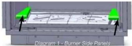
- Remove rear log tray by removing 3 screws as shown in Diagram 2 below.

natural_image
3D mechanical assembly diagram showing a component with green and gray parts, no visible text or symbols- Unscrew the 2 front NG log pins. Relocate those pins to the rear holes and reinstall.

- Remove burner by removing 3 screws in locations shown below.

natural_image
3D diagram of a mechanical assembly inside a transparent enclosure, showing internal components and mounting points (no text or symbols)Diagram 3 - Burner Screw Locations
- Pull off the pilot cap to expose the pilot orifice (see below).

- Unscrew the pilot orifice with the Allen key and replace with the propane/ULPG pilot orifice in the kit and replace pilot cap (see right).
- Remove burner orifice with a 12mm spanner and discard. Use another spanner to hold on to the elbow below the orifice.
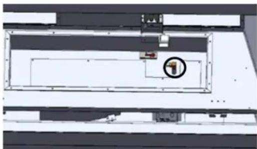
natural_image
Architectural floor plan showing structural components and a highlighted circular detail (no text or labels)- Reinstall new burner orifice Propane/ULPG and tighten. Burner Orifice #47 (Propane) Burner Orifice # 49 (ULPG)
- Adjust air shutter to fully open for both propane/ULPG.
- Do steps 1-5 in reverse order.

- Remove 4 screws to remove access panel.
Note: Access panel is no longer usable/accessible once facing material installed. - Replace the black "Natural Gas" label with the orange "Propane or red UNIVERSAL LPG" label.
- Pull ECS V module out to gain access to the DIP switch.
- Flip DIP switch #3 to the OFF position as shown to select propane as the gas type. Refer to the table for switch function information.

| DIP Switch Function Description of Function | ||
| 1 Convection Fan Control | ON-Convection fan is always on if the burner is lit.OFF-Convection fan can be switched off independent of the burner. | |
| 2 Model selection | ON-Power Flue modeOFF-Non power flue mode | |
| 3 Gas type selection | ON-Natural gasOFF-Propane/ULPG | |
| 4 Spared | N/A | |
IMPORTANT: The convection fan must always remain in the ON position. Do not turn this to the OFF position.
Note that the picture shown is what you would see when removing the ECS V control module from the appliance.
- Adjust Air shutter to fully open for both LP/ULPG.
- Place ECS V module back into the unit and reinstall the access panel.
- Remove the plug from the tee.

natural_image
Close-up of a mechanical assembly with brass fittings and wiring (no visible text or symbols)- Ensure 20 on the dial of the pressure switch is in line with the pressure settings marker, as shown in the image below. Apply pipe sealant to pressure switch and install on tee. When installing pressure switch to gal tee, ensure it is tightened as per following diagrams.
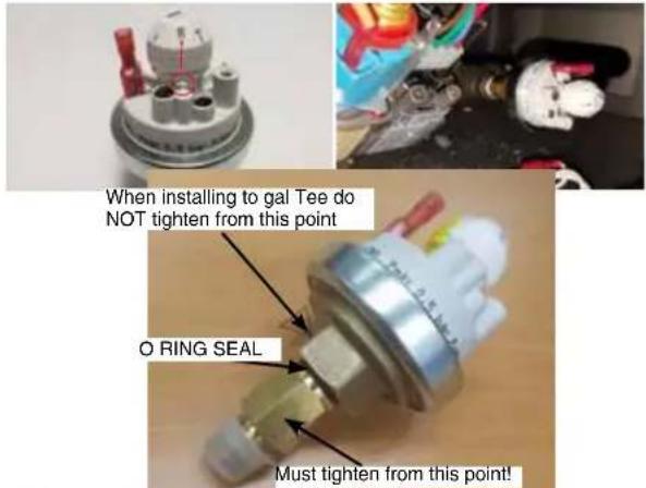
- Locate the white wire and unplug the connectors as shown in the picture below.

natural_image
Close-up of a hand adjusting a component with colored wires and a magnified inset showing the close-up (no visible text or symbols)- Connect the brown and white wires together, as shown below. Connect the white wire disconnected in step 23 and the new brown jumper wire to the low inlet pressure switch.

natural_image
Close-up of electrical wiring and components on a dark surface, no visible text or symbols
natural_image
Close-up of electrical wiring and components on a dark surface, no visible text or symbolsinstallation
- Apply new wiring diagram decal over existing one on the bottom of the unit.
- Turn on the gas supply and plug in the power cord.
- Adjust the outlet pressure. All the adjustments must be carried out in the following order:
a. Remove the modulator plastic cap (A) using needle-nose pliers.
b. Maximum pressure: Turn the unit ON to its highest input rating. Screw in the nut (B) to increase the outlet pressure and screw it out to decrease it. Use a 10 mm spanner.
Note: Do not screw nut in too far. If pressure doesn't increase after two full turns, place the mamometer on the inlet test point on the gas valve and check the flowing inlet pressure. Minimum = 2.75 kPa
Note: The maximum outlet pressure must be set to 2.49 kPa.
Minimum pressure: Remove one of the orange cables connected to the electric modulator. While holding the nut (B) with a wrench, screw in the screw (C) to increase the pressure and screw it out to decrease it. Use a suitable screwdriver.

After carrying out all adjustments, block the setting screws with paint, taking care not to obstruct the breather orifice of the pressure regulator. Put the plastic modulator cap back on.
WARNING: To ensure correct operation of the modulator, return the plastic cap (A) to its original location.
NOTE: The minimum outlet pressure must be set to 1.6 kPa.

- At the end of all setting and adjustment operations, check electrical installation and gas leaks.
- Check operation of flame control.
- Check for proper flame appearance and glow on logs.
Installer Notice: These instructions must be left with the appliance.
Propane / ULPG Wiring Diagram
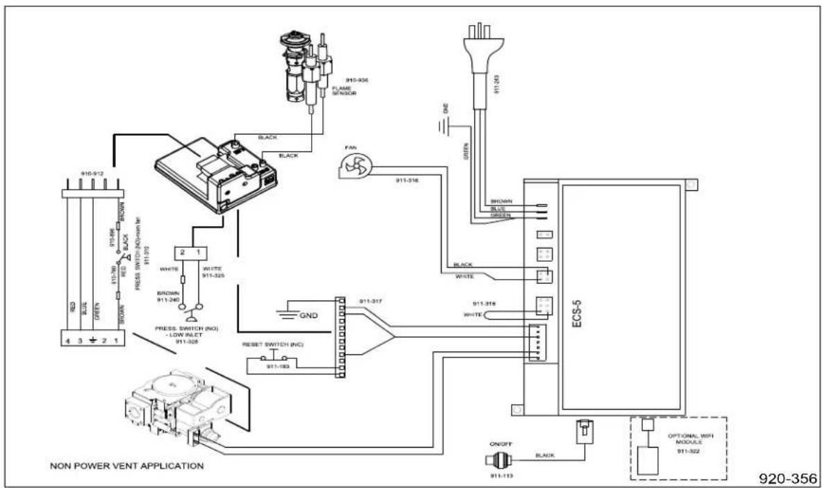
Optional WIFI App (Part #946-767) - WIFI Dongle Installation

WiFi dongle/app quick start guide.
- Remove the four Phillips head screws on the front panel plate to gain access to the ECS V control module.
NOTE
- If the appliance was completed with finishing materials and access to the ECS V cannot be gained from the front panel, see manual regarding how to access the WIFI dongle connection. Once access is gained, proceed to step 2.


- Locate the WIFI dongle connection on the left side of the ECS V control module.

- Line up the tab on the controller with the notches on the dongle.
natural_image
Close-up of a small electronic device with a white cable and a flat top, placed on a textured surface (no visible text or symbols)
natural_image
Close-up of a mechanical device with a button and a small component, no visible text or symbols
natural_image
Close-up of electrical connectors and cables in a mechanical or electronic assembly (no visible text or symbols)
natural_image
Close-up of a white electronic device with black wires and ventilation grille, mounted on a dark surface (no visible text or symbols)Properly seated:

natural_image
Close-up of a mechanical device with a black connector and cable inserted, no visible text or symbols
natural_image
Close-up of a mechanical component with a white box and black base, no visible text or symbols
natural_image
Close-up of a device with three ports and a screen, no visible text or symbols- Apply Velcro strips to the bottom of the dongle and the inside of the unit and place the control module and dongle inside the unit.

natural_image
Close-up of a metallic industrial component with visible cooling fins and a small electronic device (no text or symbols)- Reverse step 1 to close the unit.
Optional Fan Ducting Kit Installation
LISTINGS AND CODE APPROVALS
This Fan Kit has been approved for use with GF1500L.
NOTE: ENERGY LABEL RATINGS DO NOT REFLECT INSTALL OF OPTIONAL FAN KIT.
Check with your local building code agency before you begin your installation to ensure compliance with local codes, including the need for "permits" and follow-up inspections. If any problems are encountered regarding code approvals, or if you wish clarification on any of the instructions contained here, contact your local dealer.
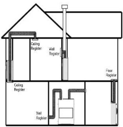
Diagram 1: Guide for possible air duct runs and locations. Keep duct length and number of bends to a minimum. Maximum duct length is 9.0m. The Extension Kit contains a maximum of up to 4.5m. Please purchase the Fan Duct Extension Kit to increase the 9.0m
| Item No. | Description No Description | |
| 1 | 240V Fan Assembly | 7 Aluminum Flex 4.5m |
| 2 | Duct Flange-Fan | |
| 3 | Adapter Round to Oval | 8 Duct Flange-Stove |
| 4 | Angle Bracket | 9 Sidewall Grille |
| 5 | Junction Box | 10 Connector Clamp |
| 6 | Wall Adapter Plate |
NOTE: The fan kit (946-591) does not contain any ducting. The optional extension duct kit (7 in the noted table) is 4.5 metres in length and its part number is 946-596.
GENERAL INFORMATION
The Fan Kit increases the effectiveness of your fireplace by dispersing warm air from the fireplace to remote locations in the same room or other rooms in your home.
Up to two kits may be installed on the fireplace.
Important Installation Notes
- The appliance installation must conform with local codes and installation codes.
- The appliance when installed, must be electrically grounded in accordance with local codes.
- This kit is tested and safe when installed in accordance with this installation manual. Please read all instructions before starting installation and follow all instructions carefully during installation.
- Installation of this kit must be performed by a qualified service technician.
- The Fan Kit must be installed only as specified. Any modifications of the kit or components will void the warranty and may cause a fire hazard.
- Plan the location of the fireplace and the warm air duct runs, see diagram 1 as a guide for possible duct runs and locations.
Maximum Duct Run: 9.0m Kit Contains 4.5m
If you require more than 4.5m please purchase Fan Duct Extension Kit.
NOTE: Airflow through the duct system is affected by the duct length and number of bends. Keep the length and bends to a minimum to maximize performance.
MINIMUM FRAMING CLEARANCES
* Wall studs must be 407mm on center for mounting fan housing.
* Fan Housing: Maintain a 6mm clearance from fan housing to combustible material.
* Wall Registers must be 102mm above floor and / or 102mm below ceiling.
1. Determine the location of the air register/fan housing assembly. Cut a 121mm x 406mm hole between framing members (wall studs or floor joists). Maintain a 6mm clearance from fan housing to combustible material. See Framing Clearances section.
MINIMUM FAN DUCT CLEARANCES
The fan ducting requires a minimum of 25mm clearance to combustibles.


Minimum 102 mm from floor
NOTE: Installation of Fan Kit should be done prior to installation of the wall.
2) Mount and secure the fan housing assembly to framing members, the front of the fan housing will protrude 12.7mm out of the wall so it may be finished with drywall, etc. See diagram 2
3. Install the air duct run. Secure the duct to the duct collar on the unit and the fan housing with 3 screws per end and aluminum duct tape.

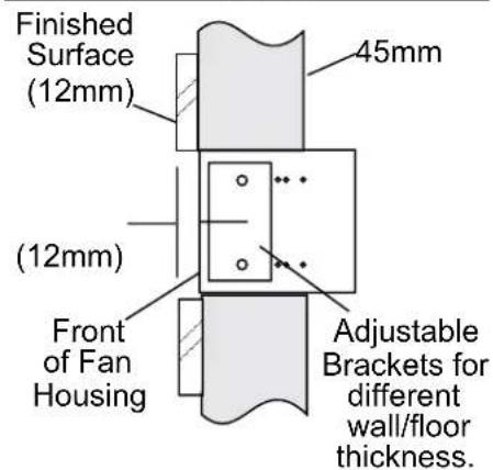
Diagram 2: Side View - Secure fan housing to minimum 45mm framing.
Round Air Duct: Attach the 152.4mm round air duct (supplied) to the fireplace collar and run the duct to the fan housing. Attach the round-to-oval adapter to the fan housing and the air duct to the adapter 4. Install the On/Off switch in a convenient location. This switch controls the fan operation.
NOTE: Variable speed or Rotary 3 speed switch can be fitted.
- Wire up the fan, wall switch and power supply per local codes. See wiring diagram as reference. *Electrician to supply wiring.
- Screw fan junction box to the fan housing.

- Screw the Register Adapter Frame and the Air Register to the Fan Housing See diagram 4.
8) Remove the knock out on the top of the unit. Cut away the insulation in a circular motion. Remove the second knock out, that is below the layer of insulations.
9) On the top of the unit, bend the 3 tabs up. Insert the Duct collar. Secure the collar to the 3 tabs with screws.
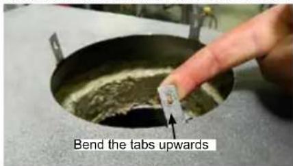

10) You are now ready to attach fan duct to the unit. Slide the ducting over the collar and secure with screws.
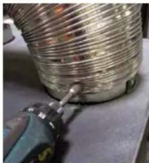
natural_image
Close-up of a coiled metal pipe being inserted into a cylindrical component, with a tool partially visible (no text or symbols)11) Final step is to double check the fan ducting connections at both the unit and fan. Next ensure there is a minimum of 25mm clearance to combustibles. Strap and secure the fan duct. Double check the operation of the fan and all electrical work is completed.
installation
- Attach the connecting collar to the duct that came with the duct kit. Use the screws provided.

natural_image
Close-up of hands operating a metal pipe with coiled tubing (no visible text or symbols)- Attach the 4.5m duct within this kit to the connecting collar on the opposite end with the screws provided. Extend the flex to the desired length.

natural_image
Close-up of a hand operating a metallic cylindrical mechanical component (no visible text or symbols)WIRING DIAGRAM
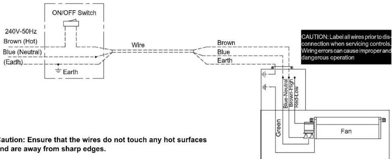
Alternate Switches: May use the following. Check with local authorities and electrician. CLIPSAL 203 2E45 OUD - Dimmer CLIPSAL 2031 VF3CSF - 3 Speed
Log Set Installation
Read the instructions below carefully and refer to the images. If the logs are broken do not use the unit until they are replaced.
Broken logs can interfere with pilot operation.
Improper positioning of the logs may create carbon build-up and can alter the unit's performance which is not covered under warranty.
Log kit # 606-930 contains the following pieces:
| Description | |
| 1 Log | 1-Rear Log |
| 1 Log | 2- Left log |
| 1 Log | 3- Center Log |
| 1 Log | 4- Right Log |
| 1 Log | 5- Front left Log Piece |
| 1 Log | 6- Front Center Log piece |
| 1 Log | 7- Front Right Log piece |
| 1 Bag | Embers |
- Install the supplied embers on exposed screw holes located on top of the ceramic burner as shown in Diagram 2.

Diagram 2
- Line up locators on Log 1 with corresponding locators on Log Tray as shown in Diagram 3.

natural_image
Close-up of a hand using a tool to inspect a textured material on a metal surface, with two circular annotations highlighting features (no readable text or symbols)Diagram 3
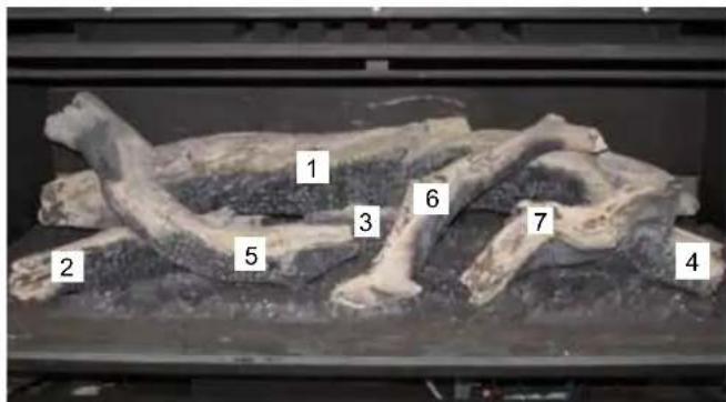
Diagram 1
Complete Log Install and Log Identification
- Line up locators on Log 2 with corresponding locators on Ceramic Log Burner as shown in Diagram 4 and 5.
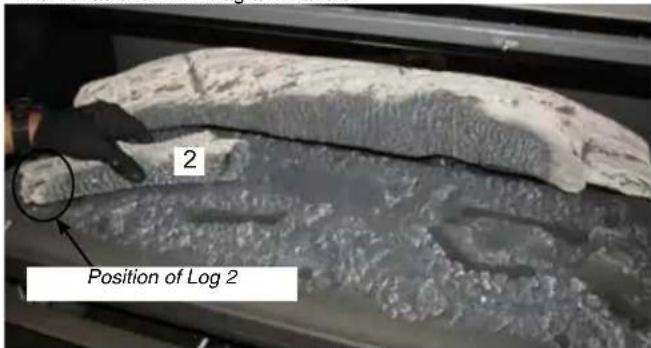
Diagram 4

- Line up the locator on Log 3 with the corresponding locator on ceramic log burner as shown in Diagram 6.

natural_image
Close-up of a textured gray surface with a hand holding a tool, labeled '3' and an inset showing a magnified view of the same material (no text or symbols on the main subject)Diagram 6
installation
- Line up locator on Log 4 with corresponding locator on Ceramic Log Burner as shown in Diagram 7.
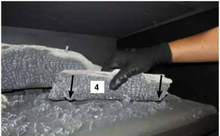
Diagram 7
- Rest Log 5 on Log 2 and Log 1 and also on the Ceramic log Burner as shown in Diagram 8 and Diagram 9.

Diagram 8

Diagram 9
- Rest Log 6 on Log 1 and also on the Ceramic log Burner as shown in Diagram 10.

natural_image
Close-up of a fish specimen with labeled parts and magnified view (no text or symbols)Diagram 10
- Rest Log 7 on Log 4 and also on the ceramic Log Burner as shown in Diagram 11.
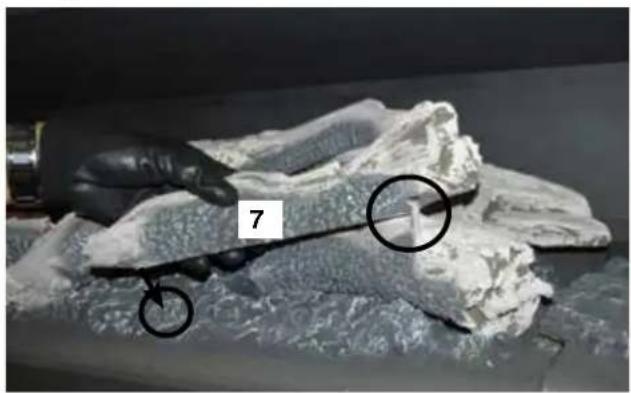
natural_image
Close-up of a gloved hand holding a textured material sample with circular annotations highlighting features (no readable text or symbols)Diagram 11
- Log 7 in final position shown in Diagram 12.
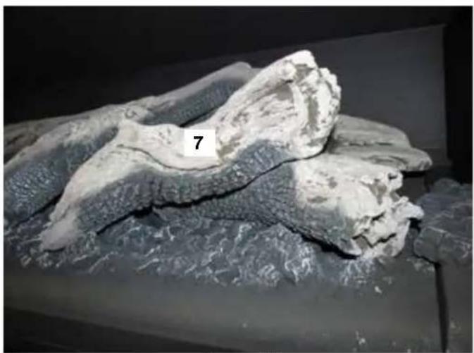
natural_image
Fossilized rock formation displayed on a shelf, showing layered sedimentary strata (no text or symbols visible)Diagram 12
Front Trim Removal/Installation
- Remove faceplate, inner door frame, and glass door if already installed - see instructions in this manual.
- Remove two (2) screws in locations shown below to remove front trim piece.
- Reverse steps to reinstall.
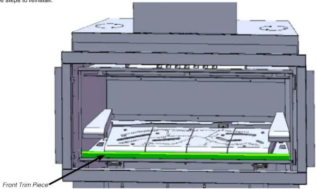
Diagram 1 - Front Trim Screw Locations
Inner Panel Removal/Installation
- Remove front trim piece - see instructions above.
- Remove two (2) screws in locations shown below to release panel clips.

natural_image
Abstract geometric shape with blue and black colors, no text or symbols visiblePanel Clip
- Remove panels by sliding out.

natural_image
Interior view of a server rack with two monitors and a central drive (no visible text or labels)- Reverse steps to reinstall.
installation
Fascia and Deflector Installation
- Install the fascia to the unit by hooking the left and right side mounting brackets into the mounting slots at the side of the firebox as shown below.
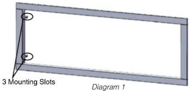
- There are 3 mounting slots available to accommodate any finishing that protrudes slightly beyond the faceplate.
- It is recommended that you use the first mounting slot (the one closest to the door frame overlay) out of the 3 so that the faceplate and door frame overlay are flush with one another. See diagram 2.
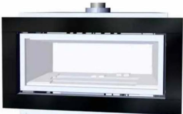
natural_image
Interior view of a modern kitchen appliance with a recessed opening (no visible text or symbols)Diagram 2
- Install deflector by using 5 screws provided to the underside of the fascia as shown in Diagram 3 and 4.

natural_image
Person using a tool to examine fish in a glass display case (no visible text or symbols)Diagram 3
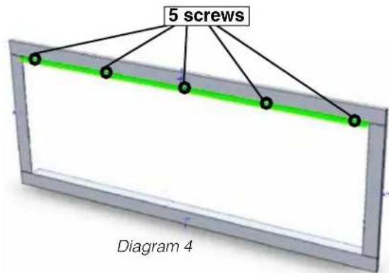

Diagram 5
- Hook the inner door frame to the unit as shown in diagram 6. Refer to "Screen and Inner Door Frame Installation" in the manual prior to installing it on to the unit.

natural_image
Diagram of a device with a slide and a scroll, showing a right-hand rule for viewing or opening (no text or symbols present)Diagram 6
- Remove any finger prints/ marks prior to operating the unit.
Screen & Inner Door Frame Installation
- Hang screen mesh over inner door frame as shown in diagram 1.

natural_image
Diagram showing a blue panel with a red curved arrow indicating rotation or change, overlaid on a 3D structural frame (no text or symbols)Diagram 1 Diagram 3
- Install screen and inner door frame to unit but hanging over glass door frame as shown in diagram 3. Lower gently once in position over glass door frame.

natural_image
Exterior view of a modern office building (no signage)- Bend tab on screen mesh to 90° as shown in diagram 2. Secure to inner door frame with one (1) screw as shown in diagram 2a.

natural_image
3D diagram of a rectangular panel with a highlighted section and an arrow, labeled 'Diagram 2' (no text or symbols on the diagram itself)Diagram 2a
installation
Finishing Trim Installation
- Install the finishing trim by lining up trim with the outside of the fascia. Press trim inward firmly to seat onto the unit.

natural_image
Technical line drawing of a mechanical housing or enclosure component (no text or symbols)- Pull trim outward-away from the unit to remove.

natural_image
Line drawing of a portable oven or storage unit with internal compartments and a top lid (no text or symbols)Finishing Trim Installed
Operating Instructions
Before operating this appliance, proceed through the following check list.
- Read and understand these Instructions before operating this appliance.
- Check to see that all wiring is correct and enclosed to prevent possible shock.
- Check to ensure there are no gas leaks.
- Make sure the glass door is in place. Never operate the appliance with the door glass removed.
- Verify that all flueing and the termination cap is unobstructed.
- Verify log placement.
- The unit should never be turned off and on again without a minimum of a 60 second wait.
- When lighting the appliance, the inside of the glass may fog up. This will burn off after a few minutes of operation.
Lighting Instructions
- Plug the power cord into a power outlet or turn on adjacent isolation switch.
- There is a black, manual, ON/OFF button located in the bottom left-hand corner of the unit. This button can be used if there is no remote control. The flame / fan patterns cannot be changed when using this button.
- After approximately 3 seconds the spark ignition system will spark for 25 seconds to light the pilot burner, then main burner will light.
- If the main burner does not light, repeat step 2 to restart the unit. See page 39 on "Resetting the unit".
Shutdown Instructions
- Press the ON/OFF switch once.
- Turn off all electric power to the appliance if service is to be performed.
First Fire
The FIRST FIRE in your heater is part of the paint curing process. To ensure that the paint is properly cured, it is recommended that you burn your fireplace for at least four (4) hours the first time you use it.
When first operated, the unit will release an odour caused by the curing of the paint and the burning off of any oils remaining from manufacturing. Smoke detectors in the house may go off at this time. Open a few windows to ventilate the room for a couple of hours. The glass may require cleaning.
NOTES
- The main burner will always start on "HIGH" and resume it's last setting after 20 seconds of operation.
- When the glass is cold and the appliance is lit, it may cause condensation and fog the glass. This condensation is normal and will disappear in a few minutes as the glass heats up.
- Do not attempt to clean the glass while it is still hot!
- Do not burn the appliance without the glass front in place.
Remote Control
Use the Regency Remote Control Kit supplied with this unit. Use of other systems may void your warranty. See page 2 for pairing of remote.
The remote control kit comes with a hand held transmitter and a wall mounting plate.
Choose a convenient location to mount the hand held transmitter, protection from extreme heat is very important.
By using the wall mounting plate to house the transmitter, the remote can also be used as a wall thermostat.

Summary of Controls
On/Off Button
If the unit is switched off, pressing and releasing this button once will switch the unit on. The unit will resume its last settings.
If the unit is switched on, pressing and releasing this button once will switch the unit off.
Flame:
Increase - If the unit is switched on, pressing and releasing the flame plus (+) button once will increase the flame height to the next available high setting.
Decrease - If the unit is switched on, pressing and releasing the flame minus (-) button once will decrease the flame height to the next available low setting.
Fan:
Increase - If the unit is switched on, pressing and releasing the fan plus (+) button once will increase the fan speed to the next available high setting.
Decrease - If the unit is switched on, pressing and releasing the fan minus (-) button once will decrease the fan speed to the next available low setting.
NOTES
- The fan will not completely turn off on this unit.
- The heater turns off when the room temperature reaches 1^ over the set temperature and turns back on when the room temperature reaches 0.5^ under the set temperature when in AUTO mode.
Fan Operation
Set the fan speed on the control panel at the top rear of the unit to adjust to the desired speed.
Pressing and releasing the plus (+) FAN button will change the fan speed as follows:
$$ \text { LOW } \rightarrow \text { MEDIUM } \rightarrow \text { HIGH } \rightarrow . $$
FAN CANNOT BE TURNED OFF
Pressing and releasing the minus (-) FAN button will be the reverse of the above.
Fan must be running at all times when the unit is in operation.
Adjusting Flame Height
There are six flame settings that can be adjusted by pressing and releasing the plus (+) and minus (-) FLAME button.
operating instructions
Copy of Lighting Plate Instructions
FOR YOUR SAFETY READ BEFORE LIGHTING
This appliance must be installed in accordance with the current AS/NZS 5601.
WARNING: If you do not follow these instructions exactly, a fire or explosion may result causing property damage, personal injury or loss of life. Improper installation, adjustment, alteration, service or maintenance can cause injury or property damage. Refer to the owner's information manual provided with this appliance. For assistance or additional information consult a qualified installer, service agency or gas supplier.
(A) BEFORE LIGHTING smell all around the appliance area for gas. Be sure to smell next to the floor because some gas is heavier than air and will settle on the floor.
WHAT TO DO IF YOU SMELL GAS - Do not try to light any appliance
Do not touch any electric switch, do not use any phone in your building
Immediately call your gas supplier from a neighbors phone. Follow the gas supplier's instructions.
If you cannot reach your gas supplier, call the fire department.
(B) Do not use this appliance if any part has been under water. Immediately call a qualified service technician to inspect the appliance and to replace any part of the control system and any gas control which has been under water.
This appliance needs fresh air for safe operation and must be installed so there are provisions for adequate combustion and ventilation air.
CAUTION: Hot while in operation. Do not touch. Severe Burns may result. Due to high surface temperatures keep children, clothing and furniture, gasoline and other liquids having flammable vapors away. Keep burner and control compartment clean. See installation and operating instructions accompanying appliance.
LIGHTING INSTRUCTIONS
STOP! Read the safety information above on this label.
1) Plug the power cord into a power outlet.
2) Press and release the ON/OFF button once to start the unit.
*ON/OFF function may be controlled by either Remote Wall Mount Control or ON/OFF control on the Unit.
3) After approximately 3 seconds the spark ignition system will spark for 25 seconds to light the main burner.
4) If the main burner does not light, check the gas and reset the unit.
TO TURN OFF GAS APPLIANCE
1) Press the ON/OFF button once.
2) Turn off all electric power to the unit if service is to be performed.
DO NOT REMOVE THIS INSTRUCTION PLATE
Normal Operating Sounds of Gas Appliances
It is possible that you will hear some sounds from your gas appliance. This is perfectly normal due to the fact that there are various gauges and types of steel used within your appliance. Listed below are some examples. All are normal operating sounds and should not be considered as defects in your appliance.
Fan:
Regency gas appliances use high tech fans to push heated air farther into the room. It is not unusual for the fan to make a "whirring" sound when ON. This sound will increase or decrease in volume depending on the speed setting of your fan speed control.
Burner Tray:
The burner tray is positioned directly under the burner tube(s) and logs and is made of a different gauge material from the rest of the firebox and body. Therefore, the varying thicknesses of steel will expand and contract at slightly different rates which can cause "ticking" and "cracking" sounds. You should also be aware that as there are temperature changes within the unit these sounds will likely re-occur. Again, this is normal for steel fireboxes.
Gas Control Valve:
As the gas control valve turns ON and OFF, a dull clicking sound may be audible, this is normal operation of a gas regulator or valve.
Unit Body/Firebox:
Different types and thicknesses of steel will expand and contract at different rates resulting in some "cracking" and "ticking" sounds will be heard throughout the cycling process.
• DO NOT SPRAY AEROSOLS IN THE VICINITY OF THIS APPLIANCE WHILE IT IS IN OPERATION.
• DO NOT USE OR STORE FLAM-MABLE MATERIALS IN OR NEAR THIS APPLIANCE.
• DO NOT PLACE ARTICLES ON OR AGAINST THIS APPLIANCE.
• DO NOT MODIFY THIS APPLIANCE.
WARNINGS
Resetting the Unit
If the appliance goes to 'lockout', the system will have to be reset by depressing the reset button
- located on the right side of the unit by outer door frame with the unit in the "ON POSITION" (fan running).
*Important: Wait at least 5 min for any unburned gas to clear before resetting the appliance.
1) Press and hold down the reset button for at least 5-10 seconds.
2) The pilot sparks can be heard and seen at the back. It will take approximately 2 to 3 seconds for the flame to be lit.
NOTES
- Wait 5 minutes between reset attempts.
- If unit fails to light after 25 seconds; wait 5 min, then manually reset using black button on the right hand side below outer door frame and follow the above steps.
Power Loss
In an event of power loss or outage, the appliance will automatically shut down. To return to normal operation, the appliance will have to be restarted by the user. To restart, press the manual ON/OFF switch on the unit or ON/OFF on the remote.

"Appliances incorporating a live fuel effect (designed to operate with blue flames with slight yellow tips) may exhibit slight carbon deposition."
Fan Service
PRIOR TO SERVICING THE FAN, ENSURE THAT UNIT HAS COOLED TO ROOM TEMPERATURE, ALL POWER IS DISCONNECTED AND GAS SUPPLY IS TURNED OFF.
- Remove faceplate, inner frame, glass door, front trim piece and inner panels - see instructions in this manual.
- Remove logs.
- Remove burner side panels by lifting out as shown in Diagram 1.
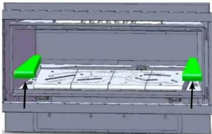
natural_image
3D mechanical assembly diagram showing a frame with green directional arrows indicating movement or force (no text or symbols present)Diagram 1 - Burner Side Panels
- Remove burner by removing 2 screws in locations shown below.

natural_image
Cross-sectional diagram of a mechanical device with internal components and mounting holes (no text or symbols)Diagram 2 - Burner Screws
- Remove rear log tray by removing 3 screws as shown in Diagram 3 below.

natural_image
3D technical diagram of a mechanical assembly with green and black components, no visible text or symbolsDiagram 3 - Log Tray screws
Greenfire® GF1500L-2 Gas Fireplace
- Remove access panel by removing eight(8) screws in locations shown in Diagram 4.

natural_image
Technical diagram of a mechanical assembly with mounting brackets and internal components (no visible text or symbols)Diagram 4 - Access Panel
- Loosen three (3) screws to remove heat deflector shown in Diagram 5.

natural_image
3D rendering of a mechanical device with blue components and circular annotations (no text or symbols)Diagram 5 - Heat Deflector Screws
- Remove two (2) screws to remove fan shown in Diagram 6.
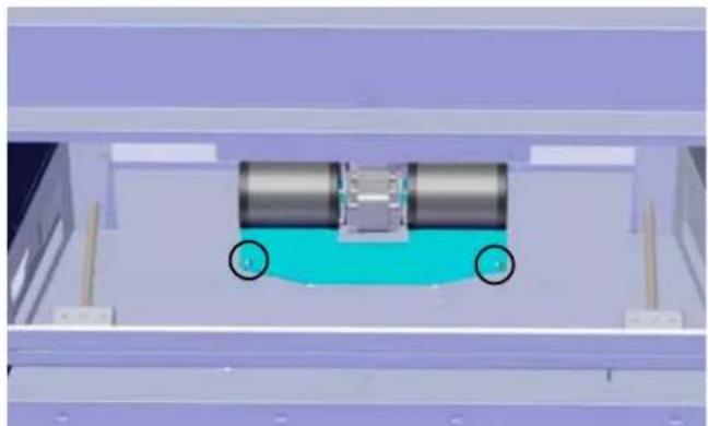
natural_image
3D diagram of a mechanical assembly with two circular annotations highlighting specific components (no text or symbols present)Diagram 6 - Fan Screws
- Reverse steps to reinstall fan.
maintenance
Maintenance Instructions
1) Always turn off the gas valve before cleaning. For relighting, refer to lighting instructions. Keep the burner and control compartment clean by brushing and vacuuming at least once a year.
2) Clean appliance and door with a damp cloth (never when unit is hot). Never use an abrasive cleaner. The glass should be cleaned with a gas fireplace glass cleaner. The glass should be cleaned when it starts looking cloudy.
3) The faceplate is finished in a heat resistant paint and should only be refinished with heat resistant paint. Regency ^® uses StoveBright Paint - Metallic Black 938-110.
NOTE
- Faceplates and inner panels made from stainless steel will naturally change color over time.
4) Make a periodic check of burner for proper position and condition. Visually check the flame of the burner periodically, making sure the flames are steady; not lifting or floating. If there is a problem, call a qualified service person.
5) The appliance and flueing system must be inspected before use, and at least annually, by a qualified field service person, to ensure that the flow of combustion and ventilation air is not obstructed.
NOTE
- Never operate the appliance without the glass properly secured in place.
6) Do not use this appliance if any part has been under water. Immediately call a qualified service technician to inspect the appliance and to replace any part of the control system and any gas control which has been under water.
7) In the event this appliance has been serviced check that the vent-air system has been properly resealed & reinstalled in accordance with the manufacturer's instructions.
8) Verify operation after servicing.
General Flue Maintenance
Conduct an inspection of the flueing system semi-annually. Recommended areas to inspect as follows:
1) Check the Flueing System for corrosion in areas that are exposed to the elements. These will appear as rust spots or streaks, and in extreme cases, holes. These components should be replaced immediately.
2) Remove the termination cap, and shine a flashlight down the Flue. Remove any bird nests, or other foreign material. Reinstall the termination cap and seal with approved sealant.
3) Check for evidences of excessive condensation, such as water droplets forming in the inner liner, and subsequently dripping out the joints. Continuous condensation can cause corrosion of caps, pipe, and fittings. It may be caused by having excessive lateral runs, too many elbows, and exterior portions of the system being exposed to cold weather.
4) Inspect joints, to verify that no pipe sections or fittings have been disturbed, and consequently loosened. Also check mechanical supports such as Wall Straps, for rigidity.
Glass Gasket
If the glass gasket requires replacement use a tadpole glass gasket (Part # 936-157).
Glass Door
Your Regency® fireplace is supplied with high temperature 5mm-Ceramic glass. If your glass requires cleaning, we recommend using an approved glass cleaner available at all authorized dealers. Do not use abrasive materials.
CAUTION & WARNINGS:
* Do not clean when the glass is hot.
* The use of substitute glass will void all product warranties.
* Care must be taken to avoid breakage of the glass.
* Do not strike or abuse the glass.
* Do not operate this fireplace without the glass front or with a cracked or broken glass front.
* Wear gloves when removing damaged or broken glass.
* Replacement of the glass panel(s) should be done by a licensed or qualified service per son.
Glass Replacement
In the event that you break your glass by impact, purchase your replacement from an authorized Regency® dealer only.
CAUTION
- Wear gloves when removing damaged or broken glass.
WARNINGS
Do not operate the appliance with the glass panels removed, cracked or broken. Replacement of the glass panels should be done by a licensed or qualified service person.
Glass Door Installation
WARNINGS
- Do not operate the appliance with the glass panels removed, cracked or broken. Replacement of the glass panels should be done by a licensed or qualified service person. Glass should be cool, if cleaning is necessary.
- Insert the door tool into the lower door latch.
Upper Door Hooks
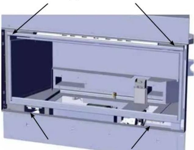
natural_image
Cross-sectional diagram of a mechanical or electrical enclosure with internal components and mounting holes (no text or symbols)Lower Door Latches

natural_image
A teal-colored metal rod or pin with a slightly extended tip, isolated on a gradient gray background (no text or symbols visible).Door Tool
- Pull forward until the lower door latch is disengaged from the door frame.
- Push downward until the Lower Door Latch is below the Door Frame.
- Release the lower door latch until it reaches its resting point.
- Remove the door tool and repeat steps 1-5 on the other lower door latch.
- Pull the bottom of the door towards you until the door is angled away from the firebox by about 30°. Lift the door up and over the upper door hooks.
- To install the glass door - reverse steps.

natural_image
3D rendering of a mechanical assembly with a green component inserted, showing no visible text or symbolsHandling of Ceramic fiber log sets and brick panels
When installing or removing ceramic fiber log sets or ceramic brick panels (if installed) from an appliance we recommend that you use latex gloves and a P1 respiratory filter be used.
We also recommend if when servicing the appliance that any items which may be replaced, not be broken up and are sealed within a heavy duty polythene bag and labeled as RCF waste.
A vacuum with a HEPA filter should be used when cleaning up remaining dust or broken bits.
Protective clothing is not required when handling these articles.
RCF waste is classed as stable, nonhazardous waste which may be disposed of at any licensed landfill site.
maintenance
Valve Tray Replacement
PRIOR TO VALVE TRAY REPLACEMENT, ENSURE UNIT HAS COOLED TO ROOM TEMPERATURE, ALL POWER IS DISCONNECTED AND GAS SUPPLY IT TURNED OFF.
- Remove faceplate, inner frame, glass door, front trim piece and inner panels - see instructions in this manual.
- Remove logs.
- Remove burner side panels by lifting out as shown in Diagram 1.
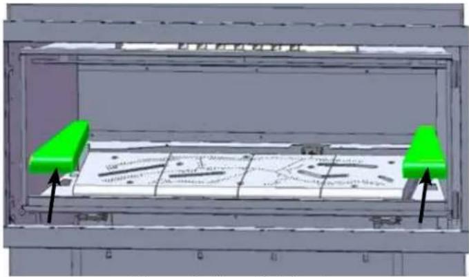
natural_image
3D mechanical assembly diagram showing green components and internal components (no text or symbols)Diagram 1 - Burner Side Panels
- Remove burner by removing 2 screws in locations shown below.

natural_image
3D mechanical assembly diagram showing internal components and part outlines (no text or symbols)Diagram 2 - Burner Screw Locations

natural_image
Close-up of a mechanical component with a highlighted section and a black arrow pointing to it (no visible text or symbols)- Remove rear log tray by removing 3 screws as shown in Diagram 3 below.

natural_image
3D technical diagram of a mechanical assembly with green and gray components, no visible text or symbolsDiagram 3 - Log Tray screws
- Remove burner by removing 16 screws in locations shown

Diagram 4 - Valve Tray Screw Locations
- Lift out valve tray.

natural_image
3D CAD model of a mechanical assembly with green highlighted components (no text or symbols visible)Diagram 5 - Valve Tray Removal
- Replace valve tray and reverse steps.
Troubleshooting Guide
| ALL WORK MUST BE CARRIED OUT BY A LICENSED/QUALIFIED TECHNICIANIt is critical that this appliance is earthed and that Active and Neutral are not crossed* Pilot light models only | ||
| SYMPTOM | CAUSE | SOLUTION |
| Unit does not operate(No ignition & No Fan) | No power supply (240V) to unit or control box | Check 240V power supply |
| Faulty ECS box | Replace ECS module & Cat 5 Cable | |
| Unit will not operate using remote control, but OK using manual control | Remote control not tuned into unit. | Tune remote control into unit |
| Remote is not tuning to the unit | Replace Remote control and or ECS module | |
| * Unit goes through ignition cycle,but pilot light does not igniteDirect Spark unitsIgniter sparks but main burner doesn't light | No gas to unit or fitting line has not been purged | Check gas supply or purge fitting line |
| * Blocked pilot | * Clean or replace pilot assembly | |
| Faulty ignition pack | Replace Ignition pack | |
| Ignitor earthing or sparking to incorrect location | Ensure sparker is in good condition, replace if necessary | |
| * Pilot light ignites but main burner does not ignite, igniter continues to spark for 10 seconds then goes to lock outDirect Spark unitsMain burner ignites but igniter continues to spark for 10 seconds then goes to lock out | Faulty sensor lead/ circuit | Check flame sensor is connected and not damaged |
| Crossed polarity, Faulty extension lead or power board | Check polarity at power point connection into heater and ECS control box | |
| Faulty Ignition Module | Replace Ignition module | |
| * Pilot light ignites but main burner does not ignite, igniter stop sparking and pilot flame stays on | No Gas to main burner | Check burner injector for blockage |
| Pressure switch not activating | Ensure Fan is running | |
| Clear any blockage in hose from pressure switch to fan. | ||
| Clean the fan | ||
| Replace Pressure switch | ||
| No power out of ignition module | Replace Ignition Module | |
Troubleshooting Guide
| Unit ignites, main burner becomes unstable, flame lifts off burner, unit goes into lockout | Incorrect burner pressure settings | Adjust burner pressure to correct setting (See Data plate) |
| Flue blocked, Incorrect flue installation or flue joints not sealed | Clear blocked flue, install flue correctly and seal all flue joints | |
| Burner aeration not correctly adjusted | Adjust burner aeration (See Unit Manual) | |
| Log set incorrectly installed | Install log set as per Owner's Manual | |
| Flue Restrictor not set correctly | Adjust Flue restrictor (See unit manual) | |
| Fan operates but no ignition sequence (no spark) | Unit ignition pack gone into lockout | Reset ignition pack by depressing black reset button while unit controls are in the "ON" position (fan running) |
| Carbon build up on glass/media/logs | Burner cracked | Replace burner |
| Log set / media incorrectly installed | Install log set / media as per owner's manual | |
| Aeration setting too far closed | Set aeration as per owner's manual | |
| Aeration blocked | Clean blockage at aeration shutter | |
| Flue restrictor not set correctly | Adjust flue restrictor as per owner's manual | |
| Partial blockage in flue | Clear blocked flue |
Gas Maintenance - Recommended Annual Routine
In order for your Regency appliance to continue to provide comfort to your home periodic maintenance must be performed to ensure it is operating at peak efficiency. The items in the list should be checked by a licensed gas service technician during the annual service check. Your unit may require more frequent maintenance checks if you notice any changes in how it operates. Operational changes to look for can include, but are not limited to, extended start up time, increased fan noise, residue/carbon build up, white build up on the glass/firebox, increased operating noise etc. Should any of these or other conditions arise, discontinue use and schedule a service check with your local licensed gas technician. The list below shows items your licensed service technician will need to check and service at least annually.
Clean
Glass
- Interior bricks / panels
- Burner ports & burner air shutter
- Fan blades
- Log set
- Pilot orifices
- Pilot hood (change as needed)
- Flame sensor (electronic ignition models)
- Flame electrode
- Burner orifice
• Thermocouple (millivolt models)
• Thermopile (millivolt models)
Inspect
- Pilot assembly
- Burner
• Pressure relief gaskets/doors - Flue connector gasket if present
- Door seal
- Firebox
- Venting
- Batteries (remote handheld, remote receiver, DC sparker, change as needed)
- Burner media (change as needed)
• Air shutter setting - Wiring
Check
• Voltage on thermocouple/thermopile (millivolt models)
- Ohms reading on flame sense (electronic ignition models)
• Inlet/outlet fuel pressures as per rating plate
• Voltage/ohms readings on gas valve
- Ohms reading to on/off switch circuit (Mili-volt models)
Gas Leak Tests
- Check main gas line connection to valve
- Check shut off valve connections
- Check connection at gas valve outlet
- Check connection at main burner orifice
- Check pilot fuel line at valve and at pilot assembly
parts list
Electronic Components Parts List
Note: Depending on the model, the diagram shown below may not depict the actual parts - for reference purposes only.
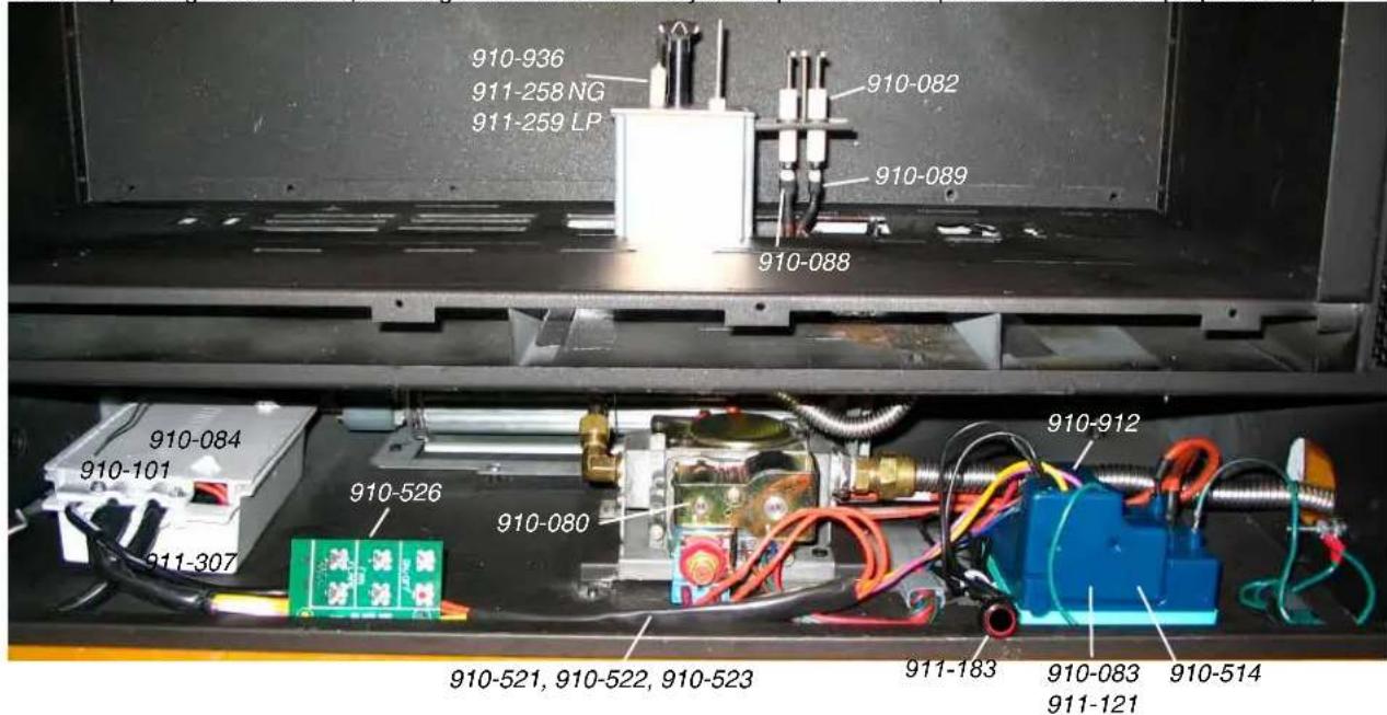
| FG38 | FG39 PG3 | 3 PG36 / | PG36D | PG121/PG131 | GFi350L | IG34 GF950L | GF950L-2 | GF1500L | GF1500L-2 | ||
| 910-909 Fan Resistor | √ | √ | √ | √ | √ | √ | √ | N/A | |||
| 910-936 Intermittent Pilot | N/A | √ | √ | √ | √ | N/A | √ | N/A | N/A | N/A | |
| 911-146 Intermittent Pilot | N/A | N/A | N/A | N/A | N/A | √ | N/A | N/A | √ | √ | |
| 911-258/911-259 Intermittent Pilot | N/A | N/A | N/A | N/A | N/A | N/A | N/A | N/A | √ | √ | N/A |
| 910-082 Direct Spark Ignitor | √ | N/A | N/A | N/A | N/A | N/A | N/A | N/A | N/A | N/A | N/A |
| 910-089 Flame Cable | √ | N/A | N/A | N/A | N/A | N/A | N/A | N/A | N/A | N/A | N/A |
| 910-088 Spark Cable | √ | N/A | N/A | N/A | N/A | N/A | N/A | N/A | N/A | N/A | N/A |
| 910-084 Control Box | √ | √ | √ | √ | N/A | √ | N/A | N/A | N/A | ||
| 911-101 Control Box | N/A | N/A | N/A | N/A | N/A | √ | N/A | √ | √ | N/A | |
| 911-307 Control Box | N/A | N/A | N/A | N/A | N/A | N/A | N/A | N/A | √ | N/A | √ |
| 910-527 Manual Control Switch | √ | √ | N/A | N/A | N/A | √ | N/A | N/A | N/A | N/A | |
| 910-080 Valve | √ | √ | √ | √ | √ | √ | √ | √ | |||
| 910-521 Control Box Cable (1)910-522 Control Box Cable (2)910-523 Control Box Cable (3)910-525 Control Box Cable (4)911-316 Control Box Cable (5)911-317 Control Box Cable (6)911-318 Control Box Cable (7)911-319 Control Box Cable (8) | *N/A | (2) | (1) | (1) | (3) | N/A | (2) | N/A | N/A(5)(6)(7) | N/A | N/A(5)(6)(7) |
| 910-912 Ignition Module to Valve Cable | N/A | N/A | √ | √ | √ | √ | √ | √ | √ | ||
| 911-183 Reset Switch | N/A | √ | √ | √ | √ | √ | √ | √ | |||
| 910-083 Ignition Module (1)911-121 Ignition Module (2) | (1)(2) | (2) | (2) | (2) | (2) | (2) | (2) | (2) | (2) | (2) | (2) |
| 910-514 Jumper Wire | N/A | √ | √ | √ | √ | √ | √ | √ | |||
| 910-935 Manual Control Switch | N/A | N/A | √ | √ | √ | N/A | √ | N/A | N/A | N/A | |
| **Note: The Control Box Cable wires for the FG38 come separately: 910-502, 910-505, 910-506, 910-507, 910-509 | |||||||||||
Main Assembly
Part # Description
-
904-777 Orifice - NG #29
. 904-434 Orifice - LP #47
904-431 Orifice-ULPG #49 -
910-080 Sigma Valve NG
910-081 Sigma Valve LP/ULPG
- 911-146 Pilot Assembly-NG
911-157 Pilot Assembly - LP/ULPG
911-121 SIT Ignition Control Module
5 396-037 Bottom Door Latch (Each)
6 606-574/P Valve Assembly-NG
606-576/P Valve Assembly-LP/ULPG
17 606-017 Door Frame Only
18 606-514 Glass Door Assembly (complete)
19 940-431/P Replacement Glass (includes Gasket)
606-004 Inner Top Baffle Plate
22 606-006 Rear Log Tray
23 606-005 Front Deflector
24 607-530 Ceramic Burner NG/LP/ULPG
25 606-008 Left Panel Bracket
26 606-009 Right Panel Bracket
27 466-060 Left Panel
28 466-061 Right Panel
29 606-063 Left Ceramic Filler
30 606-064 Right Ceramic Filler
Parts not Shown
Part # Description
606-967 Conversion Kit LP/ULPG
911-112 Pressure Switch
911-113 Switch On/Off w/Cat 5 cable
911-155/P Blower Motor
606-930 Log Set
911-183 Black Reset Button
606-028 Valve mounting gasket
606-030 Access Plate Gasket
910-036 Pilot Orifice-NG
910-037 Pilot Orifice LP/ULPG
932-009 Gas Line-from Outlet valve to Burner Orifice
904-658 Inlet Flex Line Glass SS Steel 24 inch
396-042F Plate Slide & Door Frame Tool
936-157 Glass Gasket Tadpole Tape Alum F.Core
904-691 Glass U Clips (each)
606-018 Door Trim One Piece
466-041F Nailing Strips-Sides
466-042 Nailing Strip- Top
316-089F Nailing Strip-Bottom
466-065 Tube Sensing
606-054 Shield Pilot Hood
910-054 Wire Ground ECS Module (Green)
910-780 Wire SIT Valve Wire
910-896 Wire High Temp to Power Cord
910-912 Wire Harness Module to Valve
911-047 Silicone Tubing 0.313 OD X 0.187 ID
466-097 Panel Clip
919-580 Manual
*** *** Low Inlet Pressure Switch
911-325 Low Inlet Pressure Switch Harness
911-306 Remote Control ECS V w/Wall Mount Brkt.
911-307 ECS 5 Control Box
911-316 Convection Fan Harness
911-317 ECS 5 Jumper
911-318 ECS 5 Jumper
911-243 ASM Power Cord 240V w/Lumberg Connector
parts list
Main Assembly

Accessories
Part # Description
32 606-922 Inner door frame - Black w/ Screen
606-932 Inner door frame - Stainless w/ Screen
33 606-543 Door Frame Overlay - Black
34 607-938 Fascia and Door Frame Black w/Screen
35 607-940 Slim Line Fascia and Door Frame Black w/Screen
* 607-951 Fascia Black Glass (not shown)
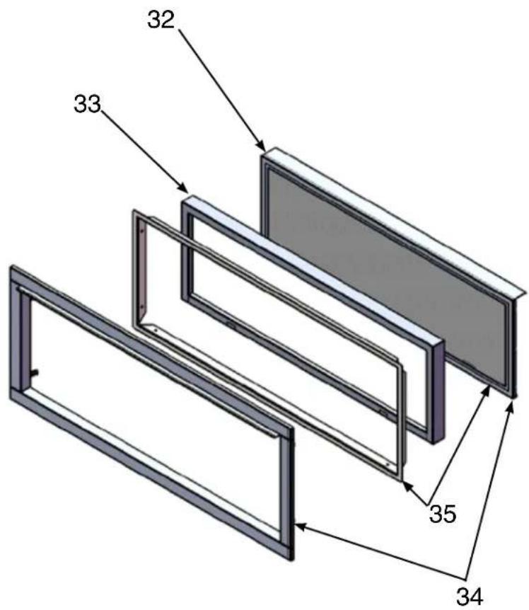
warranty
Limited Lifetime Warranty
FPI Fireplace Products International Ltd. ("the manufacturer") through its wholly owned subsidiary, Fireplace Products Australia Pty Ltd (for Australia and New Zealand customers) and sold under the Regency® brand of fireplace products (collectively referred to herein as "FPI"), extends this Limited Lifetime Warranty to the original purchaser of this appliance provided the product remains in the original place of installation. The items covered by this limited warranty and the period of such coverage is set forth in the table below.
Some conditions apply (see below).
The policy is not transferable, amendable or negotiable under any circumstances.
| Indoor Gas Products Warranty Coverage Parts and Labor | Part Lifetime | 5 years | 2 years | 1 year | Supplier Warranty | Labor Coverage (Years) |
| Firebox and Heat Exchanger | √ | 3 | ||||
| Steel Burner Tube | √ | 3 | ||||
| Glass Thermal breakage only | √ | 3 | ||||
| All Surrounds/Inlays Finishes | √ | 3 | ||||
| Brick Panels/Log sets/Ceramic Burners | √ | 3 | ||||
| All Castings | √ | 3 | ||||
| Valve assembly and all gas control components (Pilot assembly, flame sensors, Spark Electrode, Pilot Tubing, Orifices, Thermocouple, Thermopile) | √ | 2 | ||||
| All Other Electrical components with the exception of WIFI Dongle (Ignition Control Boards, Wiring, Switches, Fans, Fan Control Module, Battery Pack, Remote Control Systems) | √ | 1 | ||||
| Enamel Panels | √ | 1 | ||||
| Venting/Venting Components | √ | 1 | ||||
| All Stainless steel surrounds | √ | 1 | ||||
| All Firebox Media (Crystals, Fire beads, Volcanic, Ceramic & Spa Stones) | √ | 1 | ||||
| All hardware | √ | 1 | ||||
| Mesh/Glass Safety Barriers | √ | 1 | ||||
| Accent Light Bulbs | √ | 1 | ||||
| Glass (Crazing) | √ | 1 | ||||
| WIFI Dongle (Applicable Models) | √ | 1 |
After the original warranty coverage for any of the parts above have expired, any repair and/or replacement parts purchased by the consumer from FPI or through an accredited distributor or dealer will carry a ninety (90) day warranty (valid only with an original copy of the tax invoice). No labor coverage is included with any repair and/or replacement part.
Replacement parts are limited to one per warranty term.
Conditions:
Warranty protects against defect in manufacture or FPI factory assembled components only, unless herein specified otherwise. This warranty will only apply to those products which are acquired at the time of this warranty being effective. FPI will not be liable for any damage or loss that falls outside the scope of the warranty.
Any part(s) found to be defective during the warranty period as outlined above will be repaired or replaced at FPI's option through an accredited distributor, dealer or pre-approved and assigned agent provided that the defective part is returned to the distributor, dealer or agent for inspection if requested by FPI. Alternatively, FPI may at its own discretion fully discharge all of its obligations under the warranty by refunding the verified purchase price of the product to the original purchaser. The purchase price must be confirmed by an original copy of the tax invoice.
The authorised selling dealer, or an alternative authorised FPI dealer if pre-approved by FPI, is responsible for all in-field diagnosis and service work related to all warranty claims. This warranty does not cover dealer travel costs for diagnostic or service work. Dealers may charge homeowner for travel and additional time. Check with your selling dealer in advance for any costs to you when arranging a warranty call. FPI is not responsible for results or costs of workmanship of unauthorised FPI dealers or agents in the negligence of their service work. Additional service fees may apply if you are seeking warranty service from a dealer other than the dealer from whom you originally purchased the product.
At all times FPI reserves the right to inspect reported complaints on location in the field claimed to be defective and determine whether the warranty will apply prior to processing or authorising of any claim. Failure to allow this upon request will void the warranty.
All warranty claims must be submitted by the dealer servicing the claim, including an original copy of the tax invoice (proof of purchase by you). All claims must be complete and provide full details as requested by FPI to receive consideration for evaluation, including proof of maintenance records. Incomplete claims may be rejected. FPI has absolute discretion to assess and determine any warranty claim and may accept or reject a claim as it considers appropriate. Any part or parts of the unit found to be defective will be repaired or replaced at FPI's option, through an accredited distributor or service agent provided that the defective part be returned to the distributor or agent, Transportation Prepaid, if requested. It is the general practice of FPI to charge for larger, higher priced replacement parts and issue credit once the replaced component has been returned to FPI and evaluated for manufacturer defect.
If a consumer has a unit installed outside an accredited distributor, dealer or pre-approved service agent's service area, or the closest approved service agent is situated more than thirty (30) kilometres from the installation, FPI is not obliged to arrange warranty repairs or shipping/transportation costs. In these cases, the consumer must arrange warranty service with its selling dealer, and shipping, travel and/or additional labor charges will apply.
Unit must be installed according to all manufacturers' instructions as per the manual.
All Local and National required codes must be met.
The installer is responsible to ensure the unit is operating as designed at the time of installation.
The original purchaser is responsible for annual maintenance of the unit, as outlined in the owner's manual. As outlined below, the warranty may be voided due to problems caused by lack of maintenance. Annual maintenance records should be retained.
Repair/replacement parts purchased by the consumer from FPI after the original coverage has expired on the unit will carry a 90 day warranty, valid with a receipt only. Any item shown to be defective will be repaired or replaced at our discretion. No labor coverage is included with these parts.
Exclusions:
This Limited Lifetime Warranty does not extend to paint, rust or corrosion of any kind due to a lack of maintenance or improper venting, combustion air provision, corrosive chemicals (i.e. chlorine, salt, air, etc.), door or glass gasket.
Malfunction, damage or performance based issues as a result of environmental conditions, location, chemical damages, downdrafts, installation error, installation by an unqualified installer, incorrect chimney components (including but not limited to cap size or type), operator error, abuse, misuse, use of improper fuels, accidents, lack of regular maintenance and upkeep, acts of God, weather related problems from hurricanes, tornadoes,
warranty
earthquakes, floods, lightning strikes/bolts or acts of terrorism or war, which result in malfunction of the appliance are not covered under the terms of this Limited Lifetime Warranty.
FPI has no obligation to enhance or modify any unit once manufactured (i.e. as products evolve, field modifications or upgrades will not be performed on existing appliances).
Any unit showing signs of neglect or misuse will not be covered under the terms of this warranty policy and may void this warranty. This includes units with rusted or corroded fireboxes which have not been reported as rusted or corroded within three (3) months of installation/purchase. Any alteration to the unit which causes sooting or carboning that results in damage to the exterior fascia or over firing that can cause component or firebox/heat exchanger failure will not be covered by this warranty.
Units which show evidence of being operated while damaged, or with problems known to the purchaser and causing further damages will void this warranty.
Units where the serial no. has been altered, deleted, removed or made illegible will void this warranty.
Minor movement, expansion and contraction of the steel is normal and is not covered under the terms of this warranty.
Freight damages for products or parts are not covered under the terms of the warranty.
Porcelain/Enamel: Absolute perfection is neither guaranteed nor commercially possible. Any chips must be reported and inspected by the authorised selling dealer within three (3) days of installation. Any damage of this type not reported after this time period will be subject to rejection and any related warranty will not apply.
Special Finishes: Expect some changes in color as the product "ages" with constant heating and cooling. The manufacturer warranty does not cover tarnishing, changing colors and/or marks (i.e. finger prints, etc.) after the purchase of the product. Damage from the use of abrasive cleaners is not covered by warranty.
Products made or provided by other manufacturers and used in conjunction with the FPI appliance without prior authorisation from FPI may void this warranty.
INCORRECT INSTALLATION OR GAS PRESSURE SETTINGS ARE NOT COVERED BY WARRANTY. A SERVICE OR CALLOUT FEE WILL BE CHARGED IN THESE CIRCUMSTANCES.
Limitations of Liability:
1. Exclusion of implied terms
The customer may have the benefit of consumer guarantees under the Australian Consumer Law. To the maximum extent permitted by law, all terms, conditions or warranties that would be implied into this Warranty or in connection with the supply of any goods or services by the supplier under law or statute or custom or international conventions are excluded.
2. Limitation of liability
(a) To the maximum extent permitted by law and subject to clauses 1 and 3, the supplier's total liability arising out of or in connection with its performance or its obligations pursuant to this Warranty, or arising out of or in connection with the supply of specific goods or services (including pursuant to or for breach of this Warranty, under statute, in equity or for tort, including negligent acts or omissions) is limited as follows: (i) the supplier shall have no liability to the customer for any Consequential Loss; (ii) without limiting the effect of clause 2(a)(i), the supplier's total aggregate liability for Loss, however arising, shall not exceed the GST exclusive aggregate price paid by the customer to the supplier for the specific goods or services that gave rise to the Loss in question.
(b) The limitations and exclusions in this sub-clause do not apply to the extent that any Loss is directly attributable to: (i) the personal injury or death caused by the supplier's default, breach of this Warranty or negligence; or (ii) fraud by the supplier.
(c) Each party must take reasonable steps to mitigate any Loss it suffers or incurs.
3. Limitation of liability under Australian Consumer Law Guarantees
(a) To the extent that goods supplied by the supplier are not goods of a kind ordinarily acquired for personal, domestic or household use and the customer is deemed to be a consumer for the purposes of section 64A of the Australian Consumer Law, the customer agrees that the supplier's liability for a failure to comply with a consumer guarantee that the customer may have a benefit under the Australian Consumer Law (other than a guarantee under sections 51 (title), 52 (undisturbed possession) and 53 (undisclosed securities)), is limited to, at the option of the supplier, one or more of the following: (i) replacement of the goods or the supply of equivalent goods; (ii) the repair of the goods; (iii) the payment of the cost of replacing the goods or of acquiring equivalent goods; or (iv) equivalent goods; or (v) the payment of the cost of having the goods repaired.
(b) To the extent that services supplied by the supplier are services other than services of a kind ordinarily acquired for personal, domestic or household use or consumption, the supplier's liability for failure to comply with a consumer guarantee that the customer may have the benefit of is limited to, at the option of the supplier: (i) the supply of the services again; or (ii) the payment of the cost of having the services supplied again.
4. Subject to Change
This Limited Warranty is given at the time of sale and purchase of the relevant fireplace product. The terms of this Limited Warranty may be amended from time to time by FPI in accordance with changes to business practices, consumer laws or other legal requirements. The rights and protections granted under the Limited Warranty are those in force in relation to a fireplace product at the time and in the place of sale of that product, and only those terms will be applicable in respect of that product.
5. Severability
Any term of this Limited Warranty that is invalid or unenforceable in any jurisdiction is to be read down for the purposes of that jurisdiction, if possible, so as to be valid and enforceable, and is otherwise capable of being severed to the extent of the invalidity or unenforceability, without affecting the remaining provisions of this Limited Warranty or affecting the validity or enforceability of that provision in any other jurisdiction.
6. Definitions
For purposes of clauses 1, 2 and 3:
(a) Consequential Loss means loss of expected savings, loss of use, loss of opportunity, loss of profit, loss of revenue, increased financing costs, loss arising from delay, or any consequential, special or indirect loss or damage, whether or not the possibility or potential extent of the loss or damage was known or foreseeable, and whether arising from a claim under indemnity, contract, tort (including negligence), statute or otherwise.
(b) Loss means any expense, cost or damage of any kind and includes Consequential Loss and a fine or penalty imposed by a statutory or other authority.
warranty
How to Obtain Warranty Service:
Customers should contact the authorised selling dealer to obtain warranty service. In the event the authorised selling dealer is unable to provide warranty service, please contact FPI by mail at the address listed below. Please include your name, address, purchase date, selling dealer, serial #, type of unit, a brief description of the problem, email and telephone contact information, and a copy of your original tax invoice. A representative will contact you to make arrangements for an inspection and/or warranty service. (See below for Western Australia and/or New Zealand)
Please note Fireplace Products Australia Pty Ltd does not provide installation services.
Fireplace Products Australia Pty Ltd
99 Colmans Road
Dandenong, VIC
Australia, 3175
Phone: +61 3 9799 7277
Fax: +61 3 9799 7822
To obtain warranty service in Western Australia and/or New Zealand, please contact one of our authorised distributors in those areas:
Western Australia:
New Zealand:
Air Group Australia
28-30 Division St.
Welshpool, WA
Australia, 6106
Phone: (08) 9350 2200
Fax: (08) 9353 4225
Aber Holdings Ltd
PO Box 10095
Te Rapa, Hamilton
New Zealand, 3241
Freephone: 0800 161 161
Product Registration and Customer Support:
Thank you for choosing a Regency Fireplace. Regency strives to be a world leader in the design, manufacture, and marketing of hearth products. To provide the best support for your product, we request that you complete a product registration form at http://www.regency-fire.com.au/Customer-Care/Warranty-Registration.aspx within ninety (90) days of purchase.
Product Registration and Customer Support:
Thank you for choosing a Regency Fireplace. Regency strives to be a world leader in the design, manufacture, and marketing of hearth products. To provide the best support for your product, we request that you complete a product registration form found on our Web Site under Customer Care within ninety (90) days of purchase.
For purchases made in CANADA or the UNITED STATES:
http://www.regency-fire.com/Customer-Care/Warranty-Registration.aspx
For purchases made in AUSTRALIA:
http://www.regency-fire.com.au/Customer-Care/Warranty-Registration.aspx
You may also complete the warranty registration form below to register your Regency Fireplace Product and mail and/or fax it back to us, and we will register the warranty for you. It is important you provide us with all the information below in order for us to serve you better.
Warranty Registration Form (or Register online immediately at the above Web Site):
| Warranty Details | |
| Serial Number (required): | |
| Purchase Date (required) (mm/dd/yyyy): | |
| Product Details | |
| Product Model (required): | |
| Dealer Details | |
| Dealer Name (required): | |
| Dealer Address: | |
| Dealer Phone #: | |
| Installer: | |
| Date Installed (mm/dd/yyyy): | |
| Your Contact Details (required) | |
| Name: | |
| Address: | |
| Phone: | |
| Email: | |
For purchases made in CANADA:
For purchases made in the UNITED STATES:
For purchases made in AUSTRALIA:
FPI Fireplace Products
International Ltd.
6988 Venture St.
Delta, British Columbia
Canada, V4G 1H4
Fireplace Products US, Inc.
PO Box 2189 PMB 125
Blaine, WA
United States, 98231
Fireplace Products Australia Pty Ltd
99 Colmans Road
Dandenong, VIC
Australia, 3175
Phone: 604-946-5155
Phone: 604-946-5155
Phone: +61 3 9799 7277
Fax: 1-866-393-2806
Fax: 1-866-393-2806
Fax: +61 3 9799 7822
For fireplace care and tips and answers to most common questions please visit our Customer Care section on our Web Site. Please feel free to contact your selling dealer if you have any questions about your Regency product.
notes
Installer: Please complete the following information
Dealer Name & Address: ____
Installer:
Phone #: ____
Date Installed: ____
Serial #:
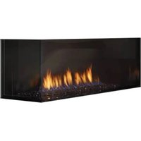
- Greenfire® GF1500L Gas Fireplace
- Owners & Installation Manual
- Warning
- WHAT TO DO IF YOU SMELL GAS
- owner's information
- To the New Owner:
- Congratulations!
- Pairing Your Remote Control
- To match the control box, follow these steps:
- Fan Operation
- NOTES
- RELEASE
- table of contents
- Installer's information
- Installation
- Operating Instructions
- Maintenance
- Parts List
- dimensions
- Unit Dimensions
- Important Message
- SAVE THESE INSTRUCTIONS
- General Safety Information
- Installation Checklist
- This Includes:
- Locating Your Gas Fireplace
- PACKAGING:
- Clearances
- IMPORTANT
- Combustible Finishing Unit Assembly/ Finishing/ Mantel Clearances + Mantel Leg Clearances
- Unit Assembly Prior To installation
- Nailing Strips-Combustible Finishing
- Installing Access Panel
- NOTE
- Clearances for Combustible Finishing with Mantel
- Combustible Mantel Leg Clearances
- Non Combustible Flush Finishing - Unit Assembly/Finishing/Mantel Clearances + Mantel Leg Clearances
- Remove top nailing strips & standoffs at side and underneath
- Installation of Access Panel
- Clearances For Non Combustible Flush Finishing with Mantel
- Non Combustible Mantel Leg Clearances
- Flushed Finishing & Framing with Non Combustible Material
- Non Combustible Requirements
- Installing a TV / Artwork Flush with the Unit
- TV Recess with 45 Degree Elbow TV Recess with Vertical Venting
- Optional Framing Kit
- Non Combustible Facing Installation
- Framing & Finishing (Clean Finish Installations Only)
- Exterior Flue Termination Locations
- mm x 203 mm Rigid Pipe - Cross Reference Chart Only
- Flue Restrictor Settings
- Flueing Introduction
- Flueing Arrangement for Horizontal Terminations
- FLUE RESTRICTOR SETTING:
- Rigid Pipe Flueing Systems - Basic Horizontal & Vertical Terminations
- Flueing Arrangements - Horizontal Termination (Flex) - Regency® Direct Vent System
- Horizontal Venting with Two 90 Elbows
- Horizontal Venting with Three 90° Elbows
- Unit Installation with Horizontal Termination (Rigid Flue Systems)
- "THIS UNIT MUST ALWAYS TERMINATE / FLUE DIRECTLY TO THE OUTDOORS."
- Unit Installation With Horizontal Termination Flex System
- Flueing Arrangement for Vertical Terminations - Vertical Flue with Two 90 Elbows (1 - 90° = 2 - 45°)
- Vertical Venting with Three 90 Elbows
- Direct Flue Zero Clearance Top Exit Vertical Flue Kit Installation Instructions
- SUPPLIED MIII-Pac SEALANT MUST BE USED OR WARRANTY WILL BE VOID - IF REQUIRED, MORE SEALANT CAN BE PURCHASED USING PART NUMBER 948-128
- Unit Installation with Vertical Termination (Rigid Systems)
- Vertical Termination - 127 mmx 203 mm Flueing - Vertical Flex Kit (Part 946-772)
- Vertical Flue Extension Kit (Approved) (Part # 946-769)
- Ceiling Firestop / Firestop Spacer (Part 946-770)
- High Elevation
- Gas Line Installation
- Pilot Adjustment
- Gas Pipe Pressure Testing
- Wiring Diagram (NG Only)
- S.I.T. Valve Description
- Aeration Adjustment
- Minimum Air Shutter Opening:
- THIS CONVERSION MUST BE DONE BY A QUALIFIED GAS FITTER IF IN DOUBT DO NOT DO THIS CONVERSION !!
- Optional WIFI App (Part #946-767) - WIFI Dongle Installation
- Optional Fan Ducting Kit Installation
- LISTINGS AND CODE APPROVALS
- NOTE: ENERGY LABEL RATINGS DO NOT REFLECT INSTALL OF OPTIONAL FAN KIT.
- GENERAL INFORMATION
- Important Installation Notes
- MINIMUM FRAMING CLEARANCES
- MINIMUM FAN DUCT CLEARANCES
- Log Set Installation
- Front Trim Removal/Installation
- Inner Panel Removal/Installation
- Fascia and Deflector Installation
- Screen & Inner Door Frame Installation
- Finishing Trim Installation
- Lighting Instructions
- Shutdown Instructions
- First Fire
- Remote Control
- Summary of Controls
- On/Off Button
- Flame:
- Fan:
- FAN CANNOT BE TURNED OFF
- Fan must be running at all times when the unit is in operation.
- Adjusting Flame Height
- Copy of Lighting Plate Instructions
- FOR YOUR SAFETY READ BEFORE LIGHTING
- TO TURN OFF GAS APPLIANCE
- DO NOT REMOVE THIS INSTRUCTION PLATE
- Normal Operating Sounds of Gas Appliances
- Burner Tray:
- Gas Control Valve:
- Unit Body/Firebox:
- WARNINGS
- Resetting the Unit
- Power Loss
- Fan Service
- PRIOR TO SERVICING THE FAN, ENSURE THAT UNIT HAS COOLED TO ROOM TEMPERATURE, ALL POWER IS DISCONNECTED AND GAS SUPPLY IS TURNED OFF.
- Maintenance Instructions
- General Flue Maintenance
- Glass Gasket
- Glass Door
- CAUTION & WARNINGS:
- Glass Replacement
- CAUTION
- Glass Door Installation
- Handling of Ceramic fiber log sets and brick panels
- Valve Tray Replacement
- Gas Maintenance - Recommended Annual Routine
- Clean
- Inspect
- Check
- Gas Leak Tests
- Electronic Components Parts List
- Main Assembly
- Part # Description
- Parts not Shown
- Accessories
- warranty
- Limited Lifetime Warranty
- Conditions:
- Exclusions:
- Limitations of Liability:
- Exclusion of implied terms
- Limitation of liability
- Limitation of liability under Australian Consumer Law Guarantees
- Subject to Change
- Severability
- Definitions
- How to Obtain Warranty Service:
- Fireplace Products Australia Pty Ltd
- Air Group Australia
- Aber Holdings Ltd
- Product Registration and Customer Support:
Brand : Regency
Model : Greenfire GF1500L
Category : Heating