D355PL - Smoke detector Fire-Lite - Free user manual and instructions
Find the device manual for free D355PL Fire-Lite in PDF.

| Product Type | Smoke Detector |
| Brand | Fire-Lite |
| Model | D355PL |
| Detection Technology | Photoelectric |
| Dimensions (Diameter x Height) | 4.1 x 1.6 in (104 x 41 mm) |
| Weight | 3.5 oz (100 g) |
| Power Source | 24 V DC (system powered) or 9V battery backup |
| Operating Temperature Range | 32°F to 100°F (0°C to 38°C) |
| Humidity Range | 0% to 95% non-condensing |
| Alarm Output | 85 dB at 10 ft (3 m) |
| LED Indicator | Red LED blinks every 40 seconds (standby), solid on alarm |
| Compatibility | Compatible with Fire-Lite alarm control panels |
| Installation | Ceiling or wall mount, 6-inch base |
| Maintenance | Test monthly, clean annually with vacuum or soft brush |
| Safety Certifications | UL 268 listed, CSFM, MEA |
| End-of-Life Signal | Chirp every 30-40 seconds indicates low battery or malfunction |
| Warranty | 5 years limited |
| Manual Format | PDF available for free download (4 pages) |
Frequently Asked Questions - D355PL Fire-Lite
User questions about D355PL Fire-Lite
0 question about this device. Answer the ones you know or ask your own.
Ask a new question about this device
Download the instructions for your Smoke detector in PDF format for free! Find your manual D355PL - Fire-Lite and take your electronic device back in hand. On this page are published all the documents necessary for the use of your device. D355PL by Fire-Lite.
USER MANUAL D355PL Fire-Lite
INSTALLATION AND MAINTENANCE INSTRUCTIONS
Innovair Flex

Fire-Ute Alarms
by Honeywell
One First Place
Northford, CT 06172
D355PL Duct Smoke Detector
SPECIFICATIONS
Operating Temperature: 4° to 158°F (20° to 70°C)
32° in 120°F (3° to 49°C) with module installed in the D355°F.
Storage Temperature: -22° to 138°F (-30° to 70°C)
Humidity: 9% to 93% Relative Humidity Non-condensing
Air Velocity: 100 to 4000 ft./min. (0.5 to 20.3 m/sec.)
Ravac-polar Footprint Dimensions: 10.38 in L × 5 in W × 2.5 in D (37 cm L × 12.7 cm W × 6.36 cm D)
Square Faceprint Dimensions: 2.75 in L = 9 in W × 2.5 in D (16.7 cm L × 22.5 cm W × 6.35 cm D)
Weight: 1.0 pounds; 0.82 kg;
Operating Voltage Range
Standby: Oment
Max. Alum Current LED an
15 to 32 VDC
300mA & 20 VDC (see communication every 5 seconds with LED Block enabled)
6.5 mm @ 24 VTX
NOTE: The D355PI, come with the sensor head factory installed, post number 5D355R.
Table of Contents Page
(1) Limitations of Duct Smoke Detectors
[2] General Description
[3] Contents of the Past Sunrise Descent Kit
141 Detector Installation
[5] Sampling Tube Installation
[6] Measurement Tests.
[1] 陈国 郑明
(5) Validation of Orctation
[3] Sertartos Cleaning Vracyume
[7] 2-Clonol Clarithm, Prochloride
[10] S### N###
(12) Optional Accessories .... 5
Warranty
BEFORE INSTALLING
Read the System Sensor Guide for Proper Use of Annate Detraces in Four Appli-
rations (505 1004), which provides detailed information on detector reacting.
placement, zones, writing, and special applications. Copies of this manual
are available online at www.sox.org/sen.com. NPà Staudals 23 and SIB
are a reliable estimate of the global financial sector. 10.2.32 valuation: 12 million for should, also be reference for the global information.
NOTICE: This manual shall be left with the owner/user of this equipment.
IMPORTANT: This detector must be tested and maintained regularly following
NAPA 74 requirements. The detector must be tested an maintained regularly
following NEPA 72 requirements. According to NEPA, the detector should be
visually inspected semiannally and functionally tested at least once a year.
This may need to be more frequent depending on the air quality of the duct
That may be to be more frequent expanding the line and quality of the line
R_H
[1]LIMITATIONS OF DOCT SMOKE DETECTORS
WARNING
Use National Fire Protection Association has established than DUCT DUTSC
TOPS MUST NOT BE USED AS A SUBSTITUTE FOR OPEN AREA DETECTOR
DISSECTION at a moment of concerning life safety. Now are then a spirit to
NOTIFICATION AS A MEANS OF PROVINCING THE SOCIETY. NOT ARE ONLY 30% (84,956) NO. 10 early warning in a building's regular tire detection system.
Early warning in a building's regular fire detection system.
System Sensor supports this position and strongly recommends that the user
read NI-FA Standards 90A, 72, and 101. The U356PL Air Duct Smoke Detection
are listed per Ul. 268A.
•
This device will not operate without electrical power. Are situations may
cause an interruption of power. The system safeguards should be discussed
with your local fire protection specialist.
This devies will not agree, smoke unless the ventilation system is occupational.
This is the WIS, the MUSE. Simult. 4.1 (CS) 1.5 (V) - V/1000-07 system in 12 months and that version is installed.
and the cover is infinite.
For this series to function properly, it MUST be installed according to the in-
structions in this manual. Furthermore, the detector MUST be operated within
ALL electrical and environmental specifications listed in this manual and the
scase local installation required. Failure to repair with these units wrote
may represent the detector from activating when receive is or sent in the air duct.
bany [A, H, I, N, E, H] and [B, G, H] and [C, P, S] in the main
| ACCESSORY CURRENT LOADS AT 24 VDC | ||
| DEVICE | STANDBY ALARM | |
| RA400Z/RA100Z | 0mA | 12mA Max |
| RT3451/RT3151 | 3mA | 12mA Max |
| RT3451KEY | 12mA | 12mA Max |
| RT3151KEY | ||
[2]GENERAL DESCRIPTION
Smoke introduced into this air duct system will be distributed throughout the entire building. Smoke detectors designed for use in air duct systems are used to sense the presence of smoke in the duct.
Model D35PL Air Dust Stroke Detector utilizes photoelectric technology for the detection of smoke. This detection method, when combined with an electric housing design, samples air passing through the dust and allows detection of a developing hazardous occasion. When sufficient smoke is secured, an alarm signal is imitated in. The fire control panel excelling the detector, and appropriate action can be taken to shut off fans, blowers, change over air handling systems, etc. These actions can facilitate the management of noise smoke and fire gases throughout the areas served by the dust system.
The D355PI incorporates a sensor cover temper feature that provides a trouble signal at the pixel immediately if the cover is removed or improperly installed. Proper installation of the sensor cover removes the trouble condition.
It programmed with the system control panel, two 120s on each duct smoke detector light to provide local visible indication.
the USSAL provides a remote alarm output for use with auxiliary devices, such as the RA400Z/RA100Z remote LED concentrator, as well as remote test capacity with the RT9451/151 or RTS651KEY/RTS151KEY Remote Test Station
[2.1] DETECTOR FEATURE SET
- Utilizes charge-in head, unit number SD358
Sampling tubes install from front and rear
- Compatible with existing accessories.
- Able to access driver per code switches on sensor head.
[3]CONTENTS OF THE DUCT SMOKE DETECTOR KIT
-
Sensor/power board assembly and covers sensor head is factory installed
-
Three +10 sheet metal recess for mounting
-
Drilling template
-
Our sampling (lbf, cal, cm)
-
line plastic exhaust tube
NOTE: A summary who must be ordered to complete the installation. It must
No. 11, if dropping that must be installed to comply with installation, it should be the correct length for the width of the duct where it will be installed. See Table 1 on page 3 to determine the inlet tube required for different duct widths
LAIDETECTOR INSTALLATION
[4-1] VERIFY DUCT AIR FLOW DIRECTION AND VELOCITY
Model D355PL detectors are designed to be used in air handling systems having air velocities of 100 to 4000 feet per minute. The widths from 6 inches in 12 feet can be accommodated. Be sure to check engineering specifications to ensure that the air velocity in the duct links within these parameters. If necessary, use a velocity meter (anemometer) to check the air velocity in the duct.
[4.2]DETERMINE MOUNTING LOCATION AND CONFIGURATION
On coats wider than 18 inches it is recommended that the detector be mounted downstream of a head, abstraction in the chest, or the supply or return air inlet.
Exemption. Installation of duct detectors can be on or within a commercial
FL 300 000
FIGURE 1. EXPLODED VIEW OF DUCT SMOKE DETECTOR COMPONENTS:
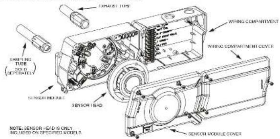
packaged rooftop heating and air-conditioning system, fire/remote dampers and concentrationers. They may be mounted in either the supply and/or return air section as determined by local code.
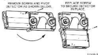
Once a suitable location is selected, otherwise if the detector is to be mounted in a ride by ride "rectangular" configuration or a top-ever bottom "square" configuration as shown to Figure 2. If murring in the square configuration, remove the rear attachment screw, rotate the unit at hinge, and replace the screw into the new attachment test as shown in Figure 3. The NOT remove the hinge screw during this process, final installation approval shall be based upon passing differential pressure and smoke entry tests described in the Measurement Test section.
Figure 2:
[4.3]DRILL THE MOUNTING HOLES
Remove the paper backing from the mounting template supplied. Edit the template to the duct at the desired mounting location. Make sure the template lies flat and smooth on the duct.
[4.3.1] FOR RECTANGULAR SIDE-BY-SIDE MOUNTING CONFIGURATION: Center punch at (4) target centers: (2) "A" for sampling tubes and (2) "B" for the rectangular configuration, showing a small amount of 1 inch diameter. Drill color holes at target "A" centers and cut two 1.375 inch diameter holes using a 1/8-inch hole saw or punch. Drill 1.36 inch diameter holes using a 50 inch drill at target "B" centers.
[4.3.2] FOR SQUARE TOP-OVER-BOTTOM MOUNTING CONFIGURATION: Center punch at (4) target centers: (1) "A" for sampling tubes and (2) "C" for the square, capping table mounting holes as shown in mounting degrees. Drill pilot holes at target "A" centers and cut two 1.375 inch diameter holes using a 15-inch hole saw or pump. Drill, 155 inch diameter holes using a 750 inch drill at target "C" centers, if desired, drill an additional 156 inch hole at the location of one of the mounting holes on the lower housing.
[4.4] SECURE THE DUCT DETECTOR TO THE DUCT
Use two [rectangular configuration] or three [square configuration] of the provided sheet metal screws to screw the duct detector in the duct. CAUTION: Du and contribution by water
LEISAMBLING TUBE INSTALLATION
15. USAMPLING TUBE SELECTION
The sampling tube must be purchased separately. Order the correct length, as specified in Table 1, for width of the duct, where it will be installed. The sampling tube length must exceed at least f_0 across the duct width for optimal performance.
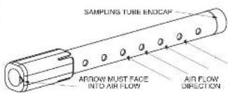
The sampling tube is always installed with the air inlet holes facing into the air flow. To solve proper filtration, the tube's connection is marked with an arrow. Make sure the sampling tube is mounted so that the arrow points into the airflow as shown in Figure 3. Mounting the descent housing in a vertical orientation is acceptable provided that the air flows directly into the sampling tube holes as indicated in Figure 3. The sampling tube and exhaust tube can be mounted in either housing connection, as long as the exhaust tube is mounted downstream from the sampling tube.
TABLE 1. SAMPLING TUBES RECOMMENDED FOR
DIFFERENT DUCT WIDTHS:
| Outside Duct Width Sampling Tube Recommended* | |
| Up to 1 ft. DST1 | |
| 1 to 2 ft. DST1.5 | |
| 2 to 4 ft. DST3 | |
| 4 to 8 ft. DST5 | |
| 5 to 12 ft. DST6 (2dpi.) | |
^1 Must extend a minimum of 12 the duct width
FIGURE 3. AIR DUCT DETECTOR SAMPLING TUBE:
1281-0
CAUTION: The sampling tube end cap, included with the detector, is critical to proper operation of the duct smoke detector. The end cap is needed to create the proper air flow to the sensor of the duct smoke detector. Once any sampling tube length adjustments are made, plug the end of the sampling tube with the provided end cap.
A plastic exhaust tube is included with the unit to be installed if exceeded. Install into the housing connection that is downstream from the sampling tube connection. The exhaust tube can be installed from the front of the detector in the back. A longer 1 fuel exhaust tube, model FTP, is available as an accessory to cases where the molded exhaust tube does not exceed at least 2 inches into the duct.
[5.2] SAMPLING TUBE INSTALLATION
-
Per tubes shower than the width of the duct slide the sampling tube, with installed end cap, into the housing connection that meets the air flow field. Position the tube so that the snow points into the airflow as shown in Figure 3. Per NIPA sampling tubes over 3 feet long should be supposed at the next opposite side of the duct detector. In ducts work than 6 feet, work must be performed inside the outlet to couple the other section of the sampling tube in the section clearly installed using the -inch constant spring supplied. Make sure that the holes on both sections or the air inlet sampling tube are tied up and facing into the airflow.
-
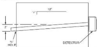
For tubes longer than the width of the duct, the tube should extend out of the opposite side of the duct. Drill a 94 inch holes in the duct up pretise the hole already out for the sampling tube. Figure 3 that the sampling tube is supplied downward from the duct smoke detector to allow for motere drainage away from the detector. The sampling tube should be angle at least 95° downward for every 10° of duct with put Figure 4. There should be 10 to 13 holes spaced as evenly as possible across the width of the duct. If there are more than a hole in the section of the recording section of the duct, or a scorsal tube using Table 1. Check the gauge tube to leave approximately 1 in inches excluding outside the duct. Plug the cord with the end ep and tape closed any hooks in the protruding section of the tube, it sure to seal the duct where the tube protrudes.
FIGURE 4
[5.4]REMOTE SAMPLING TUBE INSTALLATION
The detector arrangement can also incorporate the remote mounting or the sampling tube and/or exhaust tube. In this case both the detector, sampling tube and exhaust tube (if included) should be rigidly mounted to withstand the pressure and vibrations caused by the air velocity. The location of the detector's sampling tube should be such that there is uniform airflow in the cross section area.
Pressure differential across the sampling and exhaust ports in the detector housing shall be verified to be between 0.01 and 1.11 inches of water. Do so by measuring the pressure difference between the inner and outlet ports on the detector housing using a manometer as described in the Measurement Tests section of this manual.
[5]MEASUREMENT TESTS
[6.1] AIR FLOW
The DS55FG is designed to operate over an extended air speed range of 100 to 4000 FPM. To verify sufficient sampling of elected air, run the air handler on and use a monometer to measure the differential pressure between the two sampling tubes. The differential pressure should measure at least 0.61 inches of water and be more than 1.11 inches of water. Because most commercially available meters cannot accurately measure very low pressure differentials, applied once with less than 500 FPM of duct air speed may require one of the following: (1) the use of a current-counseling pressure transmitters (Prayer Series 867) or (2) the use of aerosol smoke, see far below for vast descriptions.
FIGURE 5. PROCEDURE FOR VERIFYING AIR FLOW:
![Fire-Lite D355PL - [6.1] AIR FLOW - 1](/content/2026/05/1041508/images/5ea881a3c52f47e154de471968648991cbfa0baa75ee3749b1a2beb60edf8b92.jpg)
1016-01
[6.2]LOW FLOW AIR FLOW TEST USING DWYER SERIES 607 DIFTERENTIAL PRESSURE TRANSMITTER
Verify the all speed of the duct, using an accommodate. Air speed must be at least 100 FPM. Weize the Dryer transmitter as shown in Figure 5. Connect the loads of the motor to other side of the 100Omega resistor. Allow lift to warm up for 12 seconds: "Well; Both HCC1 and LOW pressure sets open to ambient air, moisture and record" The voltage drop across the 100Omega detector (meas, comments 1), 4.0 volts in typical. Using Fibeste tubing and rubber stoppers, connect the HCC2 axis, of the transmitter to the gaugling tubes, of the duct device or lower heating, and the LOW mode of the transmitter to the exhaust tube of the high voltage drop. The voltage drop against the 100Omega detector measurement 21, subtract the voltage recorded in measurement 1 from the voltage recidual in measurement 2. If the difference is greater than 0.15 volts, there is enough air flow through the duct smoke detector for project operation.
[7] MIELD WIRING; INSTALLATION GUIDELINES
All wiring must be installed in compliance with the National Electrical Code and the local codes having jurisdiction. Proper wire gauges should be used. The conductors used to connect smoke detectors to control panels and accessories, which should be rated coded to prevent wiring matches. Improper conduction can prevent a system from applying properly in the event of a line. For signal wiring (the wiring between detectors or from detector to auxiliary devices), it is usually carried under that single conductor who be no smaller than 19 gauge. The duct smoke detector terminals accommodate wire sizes up to 12 gauge. Flexible conduct is recommended for the last foot of conduct; avoid conduct connections may be used if desired.
Then smoke detectors and alarm system control panels have specifications for Signaling Line Circuit (SLC) wiring. Consult the control panel manufacturer's specifications for wiring requirements before wiring the detector knot
Please refer to insert for the Limitations of Fire Alarm Systems
THREE-YEAR LIMITED WARRANTY
System license warranty is accepted product, but to free from debesis in materials and machinery under normal use and service (or a period of three years) before date of manufacture. System license makes no other expense bearing for the collection of material. So open, representative, speaker, or employee of the Company has the authority to be accepted or that the obligations of limitation are in the Warranty. The Company's obligation of this Warranty shall be limited to the replacement of any part of the product which is bound to its necessary in materials or without legal and service during the last year period commissioning with the date of manufacture. After phrasing, Service (Issuer) call for number BIS-51 NSD3L 706-7224 to a Union Association number, should defective anti-protagate prepaid to System Insurance, Ration Department, RA
3425 Ohio Avenue, St. Charles, IL 2017. Please include a note describing the information and understandable information. The Company shall not be obligated to replace units which are found to be detective because of damage, unrecognizable use, miscellaneous use, or alternate occurring after the case of manufacture. In no case shall the Company be liable for any consequential use or individual damages for loss of other or other Warranty, expressed or implied whatsoever, even if the use or damage is caused by the Company's negligence to itself. Some studies do not allow the exclusion of limitation or individual or consequential damages, so the above limitation or exclusion must not apply to this. This Warranty gives you specific legal rights, and you may also have other rights which vary from law to place.
FL 300 000 156 3255 0078
[7.1] WIRING INSTRUCTIONS
Disconnect power from the communication line before installing the D355PL duct smoke detector.
The DB35PL detectors are designed for easy wiring. The housing provides a terminal strip with clamping plates. Wiring connections are made by sliding the horn and under the plate, and tightening the clamping plate screw. See Figure 6 below for system wiring.
FIGURE 6. SYSTEM WIRING DIAGRAM FOR D355PL:
![Fire-Lite D355PL - [7.1] WIRING INSTRUCTIONS - 1](/content/2026/05/1041508/images/9b9bd9f3926355f9c7fe60dc9498d4e310f516d0e0ba28fe6fccd7e55ab66490.jpg)
flowchart
graph LR
    A["ULFM LISTED CONTROL PANEL"] --> B["1ST DETECTOR IN LOOP"]
    B --> C["2ND DETECTOR IN LOOP"]
    D["COMM. LINE"] --> E["COMM. LINE (+)"]
    F["COMM. LINE (-)"] --> G["COMM. LINE (-)"]
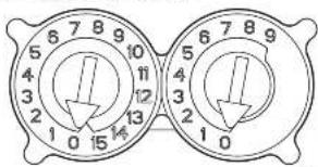
[7.2] SET THE ADDRESS
Set the desired address on the sensor head code wheel switches, on the back of the sensor head.
FIGURE 7. ROTARY ADDRESS SWITCHES
HOL1200
[8] VERIFICATION OF OPERATION
[8.1]INSTALL THE COVER
lossal the covers making sure that the cover fits into the base groove. Tighten the seven screws that are captured in the covers. Note that the cover must be properly installed for proper operation of the sensors.
[8.2] POWER THE UNIT
Activate the communication line on terminals COM - and COM -
(B.3) DETECTOR CHECK
Standby - IT programmed by the system control panel, took for the presence of the flashing, LLDs through the transparent housing cover. The LED will flush with each communication.
Trouble - if programmed by the system control panel and the detector LEDs do not then, then the detector lacks power (check wiring, missing or improperly placed uneven, panel programming, or power supply), the system load is missing [replace], or the unit is defective (return for repair).
[8.4]DUCT SMOKE DETECTOR TEST & MAINTENANCE PROCEDURES
Test and maintain duct smoke detectors as recommended in MPA 72. The tests contained in this manual were devised to assist maintenance personnel in verification of proper detector operation.
Before conducting these tests, notify the proper authorities that the smoke detection system will be temporarily out of service. Disable the zone or system under loss to prevent unwanted alarms.
[8.4.1]TEST THE UNIT
-
302-04-00 Magnet Test (not included). This sensor can be functionally tested with a test magnet. The test magnet electrocically simulates smoke in the sensing chamber, testing the sensor electronics and connections to the control panel.
-
Remote Test Accessory - The use of a remote accessory for visible indication of power and alarm is recommended.
Verely system control panel alarm status and control panel execution of all interested auxiliary functions (i.e. fan shutdown, damper control, etc.)
Two LEDs on the sensor are controlled by the panel to indicate sensor status. Coded signals, transmitted from the panel, can cause the LEDs to block, latch on, or latch off. Refer to the control panel technical documentation for sensor LED operation and expected delay to alarm.
[8.4.2] THE DETECTOR MUST BE RESET BY THE SYSTEM CONTROL PANEL [8.4.3]SMOVE ENTRY TEST USING AEROSOL SMOKE
This test is intended for low flow systems (100-500 FPM). If the air speed is greater than 500 FPM, we are conventional measureter in measuring differential pressure between the sampling tubes, as described under measurement Tests on Page 3.
Drill 2.5 inch hole: 1 feet upstream from the duct smoke detector. With the air handler on, measure the air velocity with an anemonomer. Air speed must be at least 100 FPM. Spray acrosal smoke' into the duct through the 1/2 inch hole for five seconds. Wait some results for the duct smoke detector in alarm. If the duct smoke detector alarms, air is flowing through the detector. Remove the duct smoke detector cover and blow out the residual acrosal smoke from the chamber and reset the duct smoke detector at the panel. Use duct tape to set the acrosal smoke entry hole. Remember to replace the cover after the test or the detector will not function properly.
Dacemed smoke can be purchased from Home Safety and Industries at Home-safeguard.com, model 255 Smoke Detector Tester, and Ciekkit Smoke Detector Tester model: CHER02 and CHER06 available from SFI. When used properly, the caused smoke agent will cause the smoke detector to go into alarm. See to the manufacturer's published instructions for proper use of the cannot smoke agents.
CAUTION
Canned account simulated smoke (canned smoke agent) formulas will vary by manufacturer. Mouse or averse to these products may have long term adverse effects on the smoke detector. Consult the canned smoke agent manufacturer's published instructions for any further warnings or caution statements.
[9]DETECTOR CLEANING PROCEDURES
Notify the proper authorities that the smoke detector system is undergoing maintenance, and that the system will temporarily be out or service. Disable the zone or system undergoing maintenance to prevent unwanted alarms and possible dispatch of the fire department.
[9.1]DETECTOR SENSOR
-
Remove the sensor to be cleaned from the system.
-
Remove the tensor cover by pressing, firmly on each of the four removal tags that hold the cover in place.
-
Vacuum the screen carefully without removing it. If further cleaning is required continue with Step 4, otherwise skip to Step 7.
-
Remove the chamber outlet/second assembly by pulling it straight out.
-
Use a vacuum cleaner or compressant air to remove dust and debris from the surface chamber.
-
Removal the chamber cover/screen assembly by sliding the edge over the starting element. Time until it is firmly in place.
-
Replace the cover using the LEDs to align the cover and then gently polishing it until it lies into place.
8. Reinstall the detector.
[9.2]REINSTALLATION
-
Reinstall the detector in its housing.
-
Before system power
3.Perixm:Detector Check
- Notify the proper authorities testing has been completed and the smoke detector system is back in operation.
[10]SENSOR REPLACEMENT
-
Remove the sensor head by rotating commenceswise.
-
Full gently to remove it.
-
To replace the sensor head, align the mounting features and rotate bookwise into place.
[11] OPTIONAL ACCESSORIES
Optional accessor include RA403Z/IGA1002, RTS451/RTS151 and RTS451KEY/RTS151KEY.
NOTE: Ensure blue wire always remains connected to RA - on the field connector side of the terminal block.
FIGURE 8. WIRING DIAGRAM FOR D355PL TO RA400Z/RA100Z:
![Fire-Lite D355PL - [11] OPTIONAL ACCESSORIES - 1](/content/2026/05/1041508/images/f4274b97dd787757ead3118b8e7f10f8ba27829acbbaf9bd9f0e3fa50e7c33f8.jpg)
H2570-03
Note: If using a RA100Z, the tab should be broken for use with the intelligent duct smoke detector. If using RA100Z, ensure that jumper is removed.
The ICS451/ICIS151/ICIS451KEY/ICIS151KEY Remote Test Station facilitates test of the alarm capability of the door smoke detector. These accessories provide the stimulus to initiate an alarm condition at the detector. The DSSPL due smoke detector must be used by the system control panel.
[11.1] OPTION 1:
REMOTE TEST USING SENSOR WITH REMOTE TEST CAPABILITY
(WITHOUT A TEST COIL):
A sensor with suffix "R" is available for use inside the D355PI. Suffix "R" represents a head with Remote Test Capability. Using this head inside the D355PI, eliminates the need for a test call when wired to a RTS451/RTS151/RTS451KEY/RTS151KEY Remote Test Station.
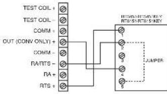
To install the RTS451/RTS151/RTS451KEY/RTS151KEY, using the sensor with remote test capability excise the device as shown in Figure 9: wire runs must be limited to 25 ohms or less par internalizing wire.
NOTE: Resistor assembly must be in place between RA+ and OUT+ inside the D355PL for Remote Test function to operate.
FIGURE 9. RTS451/RTS451KEY/RTS151/RTS151KEY USING SENSOR WITH REMOTE TEST CAPABILITY
12635-00
[11.2] OPTION 2: REMOTE TEST USING A TEST COIL:
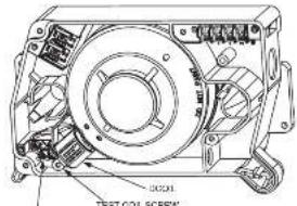
The use of a remote test station requires the installation of an accessory coil, part number DCOLL, sold separately.
1) Install DCOIL in housing socket insuring that screw is peining toward detector 2) Install DCOIL mounting screw
3) Connect each DCOIL lead to a Yee-Cell Terminal 5.4 Figure 10 below for reference.
FIGURE 10. D355PL USING A TEST COIL
TEST DOU TERMINALS
H501-01
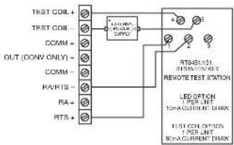
FIGURE 11. WIRING DIAGRAM FROM D355PL TO RTS451/RTS151/RTS451KEY/RTS151KEY USING A TEST COIL:
H2671-07
NOTE: The RTS451/151, RTS451/151KEY test cell circuit requires an external 24 VDC power supply which must be UL listed.
[11.3] ADDITIONAL MODULE OPTION
The DISSPI, also also accommodate a relay or control module (solid separately), within the power board side of the housing. The relay or control module must be listed as compatible to the alarm control panel.
Physical Module Mounting
- Remove the breakaway table at the four corners of the module
2] Locate the module at right most corner of the power hand. The upper left corner mounting hole at the module will align with a screw box in the box(s).
5] Install a #8 4/1" Plastic screw at the screw boss location
Note: See the corresponding module installation instructions for general description, control panel compatibility, writing and ratings.