
WL-ICNAP24-053 - Router Mach Power - Free user manual and instructions
Find the device manual for free WL-ICNAP24-053 Mach Power in PDF.


| Product Type | Wireless Router |
| Model | WL-ICNAP24-053 |
| Brand | Mach Power |
| Dimensions (W x D x H) | 170 x 120 x 30 mm |
| Weight | 0.3 kg |
| Power Supply | 12V DC, 1A |
| Wireless Standards | IEEE 802.11b/g/n |
| Frequency Band | 2.4 GHz |
| Maximum Wireless Speed | 300 Mbps |
| Ports | 4 x 10/100 Mbps LAN, 1 x 10/100 Mbps WAN |
| Antennas | 2 x External 5 dBi |
| Security | WPA2-PSK, WPA-PSK, WEP |
| Management | Web-based GUI, DHCP, NAT |
| Maintenance & Cleaning | Unplug before cleaning; use a dry cloth; avoid liquids. |
| Safety Instructions | Keep away from water and heat; use only provided power adapter. |
| Spare Parts & Repairability | Spare parts available through authorized service centers. |
Frequently Asked Questions - WL-ICNAP24-053 Mach Power
User questions about WL-ICNAP24-053 Mach Power
0 question about this device. Answer the ones you know or ask your own.
Ask a new question about this device
Download the instructions for your Router in PDF format for free! Find your manual WL-ICNAP24-053 - Mach Power and take your electronic device back in hand. On this page are published all the documents necessary for the use of your device. WL-ICNAP24-053 by Mach Power.
USER MANUAL WL-ICNAP24-053 Mach Power
for chosen our product
INDEX
Chapter 1 Hardware Introduce and Power
1.1 Interface Description
1.2 Powered by PoE Adapter
1.3 Powered by PoE Switch
Chapter 2 Run and Login
Chapter 3 Operation Mode Setting
Chapter 4 System Tools and Advanced Settings
4.1 System tools
4.2 Advanced Settings
4.3 Operation Mode
4.4 Wireless
Chapter 5 Management
5.1 System
5.2 User
5.3 Log
5.4 Upgrade firmware
5.5 System Time
CHAPTER1
HARDWARE INTRODUCE AND POWER
1.1 Interface Description

1.2 Powered by PoE Adapter
The connection diagram showed as P2, internet cable connect to PoE adapter's LAN Port, Ceiling AP's RJ45 port connect to PoE adapter's PoE Port, then PC will access into ceiling AP through wireless.
![graph TD A["Internet"] --> B["Router/Switch"] B --> C["PoE Adapter"] C --> D["Ceiling AP"] D --> E["PC"] C --> F["RST"] C --> G["WAN"] C --> H["LAN"] C --> I["LED"] C --> J["DC"] style A fill:#f9f,stroke:#333 style B fill:#ccf,stroke:#333 style C fill:#cfc,stroke:#333 style D fill:#fcc,stroke:#333 s…](/content/2026/05/1041259/images/93f871ea569dd49ae53427f46b380ecfaf437a70b82703e480715e9ffeb8ab22.jpg)
1.3 Powered by PoE Switch
The connection diagram shows as P3, Internet cable from PoE Switch to Ceiling AP's WAN Port, then PC access into ceiling AP wired/wireless. Pls note, the PoE switch should be 24V Passive PoE, can supply power together with data transmission.
![graph LR A["Internet"] --> B["Gateway AP Controller"] B --> C["PoE Switch"] C --> D["AP"] D --> E["Mobile Device"] D --> F["Computer"] style A fill:#f9f,stroke:#333 style B fill:#ccf,stroke:#333 style C fill:#cfc,stroke:#333 style D fill:#fcc,stroke:#333 style E fill:#cff,stroke:#333 style F fill:#f…](/content/2026/05/1041259/images/a5511b23a8e1ee55d29bbe1afc7cb52d2dc5629e5c9ee169df29f6c3fee95937.jpg)
CHAPTER2
RUN AND LOGIN
- Power this in wall AP in right way
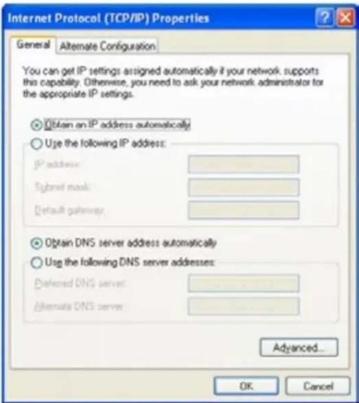
- Set an IP address for your PC: this Wireless Access Point default IP is 192.168.0.254, configure local IP address as 192.168.0.X(X can be selected from 1-253), the same network segment as this access point, subnet mask is 255.255.255.0

- Connect Wireless Access Point with PC by Wireless
Pls note, then the default SSID is MachPower2.4, default passwords are 12345678.
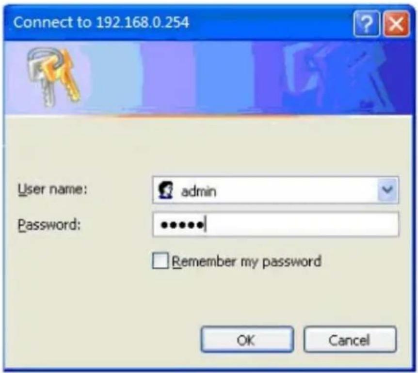
- Log in: Type 192.168.0.1 in your IE, will pop up following picture, pls input admin/admin in User name/Password to Log into this in wall AP
CHAPTER3
Let's show how to set it from Quick Setup
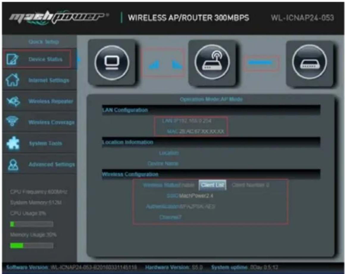
- Log into 192.168.0.254 in your Internet Explorer and input user name/Passwords, following device status will be showed, including LAN IP address, AP's MAC, Wireless Configuration, channel.
Please note:
- If signal strength "■■■" show blue, mean work fine.
- if signal strength “■■■” show red, should be some problem.
From this page, can see there are Internet Settings, Wireless Repeater, Wireless Coverage operation mode, user can choose the right operation mode based on needs.
A. Internet Setting: In this mode, the device is supposed to connect to internet via ADSL/Cable Modem. The NAT is enabled and PCs in LAN ports share the same IP to ISP through WAN port. Then connection type can be setup in WAN page by using PPPoE, Diynamic IP or Static IP.
Click Internet Settings, then will see following page, pls choose dyna-
mic IP or PPPOE based on your networking, then input the user name, passwords in PPPOE part, after that can change the SSID, Channel, Key as you like, then apply.

B. Wireless Repeater: In this mode, the in wall AP will extend the exist wireless networking signal for more range after bridge it SSID and all interfaces. Without NAT, firewall and all network related functions.
Click Wireless Repeater, then will see following page:

Then scan AP, choose AP, input AP's passwords to finish the connection setting
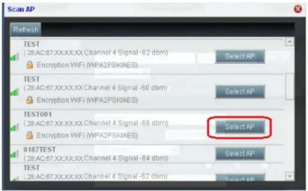
If you want to change this device's SSID, channel, Key, then set it from Wireless Part in P10. After that, then apply.
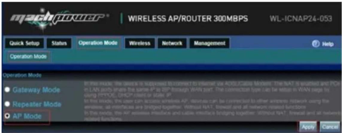
C. AP Mode: in this mode, LAN internet is from the top gateway to Switch, then to in wall AP, the wired networking will change to Wireless network and DHCP disable via this operation mode.
Click wireless coverage, then will appear following page, change the SSID, Key, Channel as you like, then apply.

After finish the setting, then cancel the IP address you set for your PC, then the internet setting is finished.
CHAPTER4
SYSTEM TOOLS AND ADVANCED SETTINGS
4.1 System tools

In system tools, you can ping any IP address/Domain easy to check the AP's working status.
4.2 Advanced Settings
In this is part, users can set the Wireless AP's networking function or other functions. Mainly for administrator.
Click Advanced Setting, the wireless AP's basic status, WiFi Status and LAN status will pop up as showed in following picture

4.3 Operation Mode
In this part, same as the 3rd part we showed. Just more choose and setting for users
4.4 Wireless
Basic Settings: In this part, just to set the SSID, password for this wireless AP.
![machPOWER® WIRELESS AP/ROUTER 300MBPS WL-ICNAP24-053 Quick Setup Status Operation Mode Wireless Network Management Basic Settings Virtual AP VLAN Settings Access Control Advanced Settings Basic Setting State Enable Disable SADC MachPower2.4 Video:B.G.N Resource ETSI Channels:T [2.442 GHz] Intelligen…](/content/2026/05/1041259/images/9ab7214d70cbc28d3cf969b43231fca2688c5cb95f7f5a832fe73122e47353ba.jpg)
Virtual AP: For this Wireless AP, support 3 Virtual SSID, but disable in default. If want to set VLAN for this wireless AP, enable this virtual SSID as following step

VLAN Settings: For this part, mainly for the tag VLAN, input the switch's VLAN ID the white blank part, then apply to finish. Pls note, the VLAN ID is from 0 to 4094.

Access Control: In this part, mainly to control the access users.
User can set it based on the networking environment.

Advanced Settings: In this part, user can configure the AP's mode, channel, Fregament Threshold, coverage threshold, Max Station.
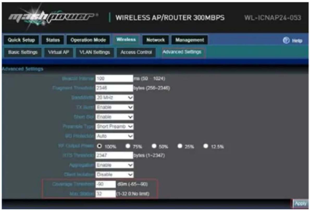
Remark: For Fragment Threshold, RTS Threshold, Beacon Interval, Aggregation, ShortGI, Rev Option, we recommend to keed in default.
Max Station, mean QTY of end users. 0 mean no limited.
Coverage Threshold: Applicated in Roaming mainly, the working status showed as follow:

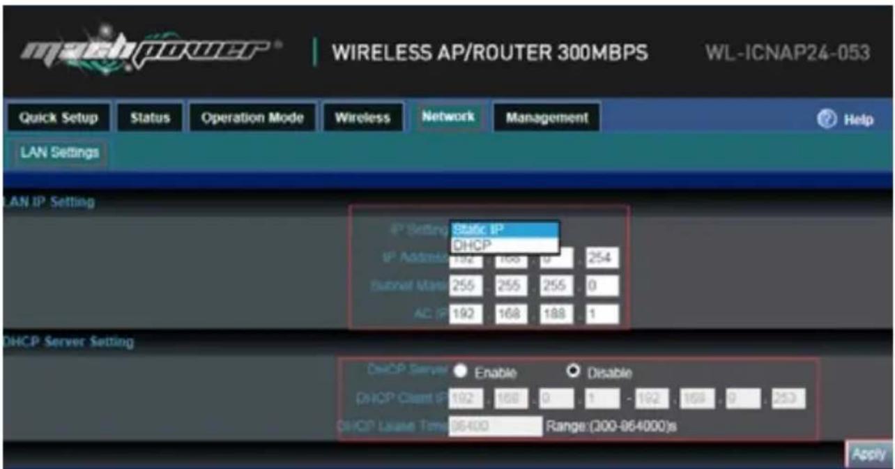
Network: In this part, mainly refer to LAN setting, including DHCP and Static IP, default is DHCP.
CHAPTER5
MANAGEMENT
5.1 System
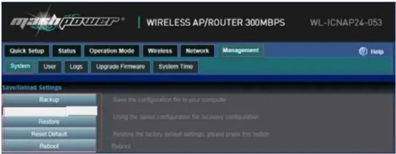
Backup: Save the configuration files to your computer
Restore: Using the saved configuration file recovery configuration
Restore default: Restore the factory default settings, please press this button
Reboot: Reboot the system
5.2 User
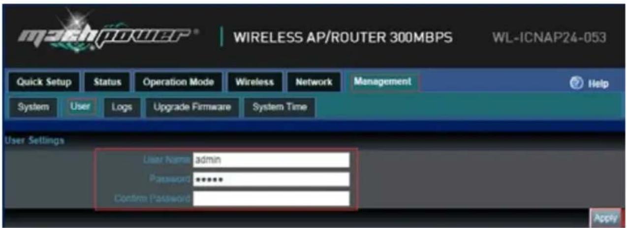
User Name: Reset new log-in user name
Password: Reset new log-in password
Confirm Password: Comparison to new password, to confirm user input password correctly in two times;
5.3 Log

Status: Enable or Disable to show wireless AP's working log
Remote Log Service: To decide whether send this log into some pointed remote server synchronously
5.4 Upgrade firmware
![WIRELESS AP/ROUTER 300MBPS WL-ICNAP24-053 Quick Setup Status Operation Mode Wireless Network Management Help System User Logs Upgrade Firmware System Time Upgrade Firmware Software Version W-ICNAP24-053-B20180331145118 For software upgrade 1. Click on [Browse] and select the software to be upgraded…](/content/2026/05/1041259/images/ff0980bc2cf98036c8c9441397cae714676cface07004871fc5a3abaaa8bca98.jpg)
Browse and choose the firmware should upgrade from above picture, then click upgrade.
After that click Reset Default from System to finish firmware upgrade
5.5 System Time

Synchronization with the host: Synchronization time with connected PC and router
Status: Enable or Disable NTP
NTP Server: Select the server time synchronization
Custom NTP Server: Setting user-defined synchronization server IP address
Time Zone: Setting the router's time zone

- FOR CHOSEN OUR PRODUCT
- INDEX
- CHAPTER 1 HARDWARE INTRODUCE AND POWER
- CHAPTER 2 RUN AND LOGIN
- CHAPTER 3 OPERATION MODE SETTING
- CHAPTER 4 SYSTEM TOOLS AND ADVANCED SETTINGS
- CHAPTER 5 MANAGEMENT
- CHAPTER1
- HARDWARE INTRODUCE AND POWER
- 1.1 INTERFACE DESCRIPTION
- 1.2 POWERED BY POE ADAPTER
- 1.3 POWERED BY POE SWITCH
- CHAPTER2
- RUN AND LOGIN
- CHAPTER3
- PLEASE NOTE
- CHAPTER4
- SYSTEM TOOLS AND ADVANCED SETTINGS
- 4.1 SYSTEM TOOLS
- 4.2 ADVANCED SETTINGS
- 4.3 OPERATION MODE
- 4.4 WIRELESS
- CHAPTER5
- MANAGEMENT
- 5.1 SYSTEM
- 5.2 USER
- 5.3 LOG
- 5.4 UPGRADE FIRMWARE
- 5.5 SYSTEM TIME
Brand : Mach Power
Model : WL-ICNAP24-053
Category : Router