DP-8 - Dimmer Adastra - Free user manual and instructions
Find the device manual for free DP-8 Adastra in PDF.

User questions about DP-8 Adastra
0 question about this device. Answer the ones you know or ask your own.
Ask a new question about this device
Download the instructions for your Dimmer in PDF format for free! Find your manual DP-8 - Adastra and take your electronic device back in hand. On this page are published all the documents necessary for the use of your device. DP-8 by Adastra.
USER MANUAL DP-8 Adastra
Caution: Please read this manual carefully before operating
Damage caused by misuse is not covered by the warranty
Introduction
Thank you for choosing an Adastra DP-8 digital power schedule controller for power automation of installed sound, lighting and service equipment. This unit is designed to provide flexible scheduling and automation of 8 power outlets, fully programmable by the operator. Please read this manual to gain the best results from your product and avoid damage through misuse.
SAFETY SYMBOL AND MESSAGE CONVENTIONS

CAUTION
RISK OF ELECTRIC SHOCK DO NOT OPEN
AVIS
RISQUE DE CHOC ELECTRIQUE NE PAS OUVRIR


This symbol indicates that dangerous voltage constituting a risk of electric shock is present within this unit

This symbol indicates that there are important operating and maintenance instructions in the literature accompanying this unit.

SAFETY NOTICE
- Prior to use, read through this manual
- Keep the manual in good condition
- Pay attention to safety warnings
- Observe all operating requirements
- Do not use the device near water or wet areas
- For cleaning, only use a lint-free, dry cloth
- Install according to the specifications
- Place away from heat sources or heating appliances
- Use mains lead provided and avoid damage to cable or connectors
- Unplug power from mains during stormy weather or if unused for long periods
- In case of malfunction, water ingress or other damage, consult qualified service personnel
- Do not place in damp areas or near liquids or moisture. Do not spill liquids on the housing
- Please pay attention to warning symbols during transit and placement
- Terminals marked with the 12 symbol are HAZARDOUS LIVE and should only be connected by qualified personnel
- Ensure that the apparatus is connected to a mains socket with a protective EARTH connection
- Ensure correct operation of the mains switch
Note: This equipment is designed to be wired directly to mains power and should be installed by a qualified electrical engineer.
The unit is hard-wired with a 36A mains cable.
If a domestic plug is connected to this, the rating may be reduced.
Warning
• To prevent the risk of fire or electric shock, do not expose any components to rain or moisture.
- If liquids are spilled on the casing, stop using immediately, allow unit to dry out and have checked by qualified personnel before further use.
- Avoid impact, extreme pressure or heavy vibration to the case
- No user serviceable parts inside – Do not open the case – refer all servicing to qualified service personnel.
Placement
• This unit can be used free-standing or fixed into a 19" rack
- Ensure adequate support and access to controls and connectors when rack-mounting
Cleaning
• Use a soft cloth with a neutral detergent to clean the housing as required
- Do not use strong solvents for cleaning the unit
Front panel

text_image
adastra DP-8 DIGITAL POWER SCHEDULE CONTROLLER ON OFF ESC MENU ENTER HOLD FOR MENU 1 2 3 4 5 6 7 8 + + OFF ON CLEAR CLEAR- Main circuit breaker
- Settings / Display button
- Enter / Timer enable button
- Escape / Protect alarm button
-
LCD display
-
Numerical program / activate buttons
- < and > buttons (previous/next page select)
- On/Off and +/- menu edit buttons
- Clear / lock button
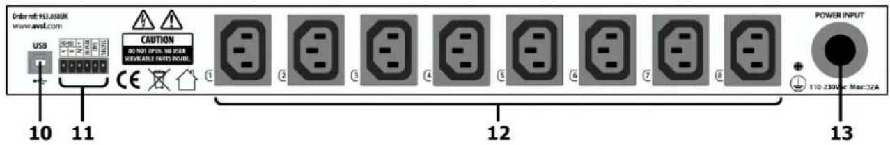
Rear panel
text_image
Order ref: 953.0580K www.awst.com USB 10 11 CAUTION DO NOT OPEN, NO USER SERVICABLE PARTS INSIDE. 12 POWER INPUT 13 110-230Vcc Max:32A- USB connector
-
Remote control terminals
-
IEC power outputs
- Mains inlet cable
Setup and Current Capacity
Warning! the DP-8 and connected equipment must be isolated from the mains supply during the following setup.
The DP-8 is powered via a hard-wired mains cable via a circuit breaker rated at 32A.
This can be connected directly to the 110V or 230V mains power supply for maximum power capacity.
For low power applications, a standard mains plug may be used but the current will then be limited to any fuse fitted in the plug.
Note: Make all other connections before connecting power to the DP-8.
Mains appliances can be powered from any of the 8 IEC power outlets (12) on the rear panel of the DP-8.
Each of these is served by an electro-mechanical relay, which is in turn controlled by the DP-8 internal programming.
The DP-8 may not be suitable for powering from other equipment which may be sensitive to an inductive load, such as a DC inverter.
The maximum total load at any time is governed by the main circuit breaker (1) or mains fuse if the DP-8 is powered from a UK plug. The main circuit breaker is re-settable, but this is a safety device and should not be used to gauge the overall current throughput.
The DP-8 has built in alarms which can be set by the user to help avoid overloading.
Connect each appliance to one of the IEC outlets.
Make sure that the total current load will not exceed the fuse or breaker if all IEC outputs are activated at the same time.
If more than one single appliance is to be powered from any of the IEC outlets, a splitter or distribution block may be used, so long as the combined load on the individual IEC outlet is less than 10A.
For very high-power configurations, any of the IEC outputs can be used to remotely switch higher current capacity 110V or 230V contactors, which deliver the high current load to the appliances, using the DP-8 output just as a trigger with minimal current demand. If all 8 channels are remotely triggering contactors, the DP-8 may be considered as a control device rather than a power distributor and can easily be powered by a 13A UK plug.
When all IEC outlet connections are made, there are control signal options which should be connected if required.
A group of 6 plug-in screw terminals have connections for 12V remote control and RS485 connection.
A description of the 12V remote operation is detailed on the next page.
The RS485 connections are for future development
A USB connector is also provided for future development and for firmware upgrading.
Remote Operation
The DP-8 has 4 screw terminals to allow global control of the power schedule using a switch or 12V remote trigger.
Connecting a switch across the +12V and REM IN terminals will operate as a global ON/OFF switch for the DP-8.
When the switch is closed, the power schedule will switch on and off as programmed. When the switch is open, the power schedule will be disabled.
Likewise, an external 12V trigger can be used by connecting +12V to to REM IN and 0V to GND.
Further DP-8 units can be controlled in tandem by connecting STATUS of a switched DP-8 to the REM IN of another DP-8.
For this operation, both GND terminals will need to be connected.
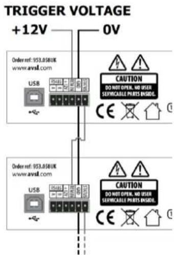
text_image
TRIGGER VOLTAGE +12V 0V Order ref: 953.058UK www.avsl.com USB CAUTION DO NOT OPEN, NO USER SERVICABLE PRAYS INCLUDE: CE Order ref: 953.058UK www.avsl.com USB CAUTION DO NOT OPEN, NO USER SERVICABLE PRAYS INCLUDE: CE
text_image
SWITCH Order ref: 953.0580K www.avsl.com USB EA401 EA402 EA403 CAUTION DO NOT OPEN, NO USER SERVICABLE PARTS ENABLE. CE Order ref: 953.0580K www.avsl.com USB EA401 EA402 EA403 CAUTION DO NOT OPEN, NO USER SERVICABLE PARTS ENABLE. CEPowering up
When all connections are made, with the main circuit breaker (1) in the "OFF" position, connect power to the DP-8. Switch the power supply on and power up the DP-8 by switching the main circuit breaker to the "ON" position.
Display Layout
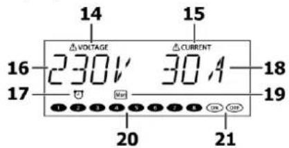
text_image
14 15 VOLTAGE △ CURRENT 230V 30A 16 17 18 19 20 2114 Voltage alarm indicator
15 Current alarm indicator
16 Mains voltage display
17 Timer schedule active indicator
18 Mains output current display
19 Day indicator for timer schedule
20 IEC outputs active indicators
21 On & Off indicators
The DP-8 display is multi-functional, showing the status during normal operation and parameter values in the settings menu.
During initial power-up, there is a scrolling "ADASTRA" greeting and then the display shows the mains voltage and current values. The display is backlit, which dims after approximately 40 seconds if there are no buttons pressed.
The 8 output channels can be operated manually by switching any of the front panel buttons (6) on or off. (this will not be effective if any channels are set to be always on as detailed in the Bypass setting section)
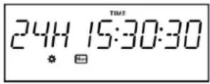
Press and hold the Settings/Display button (2) to change the display to the current time & day.
Press and hold again to revert the display to mains voltage and combined current draw through the 8 outputs.
If the panel is locked, the display will show "CODE" and the key code will need to be entered before the panel will function (see below). A short press of the Settings/Display button enters the settings menu as described below.
Settings menu
Press the Settings/Display button (2) to enter the Settings menu and step through the different options using the < and > buttons (7), which also serve as numerical buttons 7 & 8. Press the Enter button (3) to select a parameter to set.

Pressing the ESC button (4) will escape the settings menu and revert to the normal operation display (i.e. not settings menu)
Clock setting

Press the Enter button when the display shows "CLOCK" and the current time will be shown.
Use the < and > buttons (7) to step through Day, Hours, Minutes and Seconds. For each section, set the current day and time using the +/- buttons (8) Press the Enter button to save the time and return to the settings menu options
If you decide not to save the adjusted time setting, press the Escape button (4) to return to settings menu options.
Protect setting

The DP-8 has the capability to help protect connected equipment against excess voltage or current.
It is normal for mains supply to stray up or down from the stated voltage. This can depend upon the regional or local conditions and may be critical for sensitive equipment.

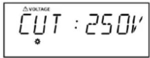
An alarm voltage value can be stored in the DP-8, above which an audible alert is activated. The alarm can be stopped by pressing the ESC or Lock button. A further maximum voltage value can be stored in the DP-8, above which the 8 outputs will cut out.
An alarm current value can also be stored in the DP-8, above which an audible alert is activated. A further maximum current value can be stored in the DP-8, above which the 8 outputs will cut out.

Use the < and > buttons to step through voltage alarm, voltage cut, current alarm & current cut. In each case, the voltage or current value can be set using the +/- buttons (8)
It is necessary to set the alarm value for each lower than the cut value. If an alarm value is set higher than the cut value, the display will show "MISTAKE" and not allow the value to be saved. Likewise, if a cut value is set lower than an alarm value, it cannot be saved.

Once the values are set, press the Enter button to save the settings or ESC to exit without saving.
Note: if the current exceeds 32A or if there is a short circuit, the main circuit breaker will trip.
Timing program

The DP-8 timing program enables the installer to program a schedule for one or more of the IEC outputs to be switched on or off. There are 99 internal events which can be scheduled by days, hours, minutes and seconds.

From the settings menu, step through the options until "TIMING PG" is displayed and then press "Enter". The number "01" will flash in the display, representing event number 1.
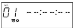
Step through the programmable events (01-99) using the +/- buttons until the required event is reached.
Press the Next button (numerical button number 8) and the 'Hours' value will flash. Set the hours value using the +/- buttons and then press the Next button to move onto the 'Minutes' value. Set the minutes value using the +/- buttons and then press the Next button to move onto the 'Seconds' Set the seconds value using the +/- buttons and then press the Next button to move onto the 'Days' value.
Set which days the event will be active by pressing the numerical buttons 1-7.
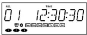
It is possible to set 1 day of the week, several days or every day.

When the active day(s) are set, press the Enter button and select which IEC outlets will be active using the numerical buttons 1 to 8. Alternatively, selecting "ON" or "OFF" will instead trigger the LEARNING ON or OFF sequence (see below) at the selected time. Press the Enter button again and the display will show "STORE - OK" and the event will be saved. Otherwise, press the ESC button to exit without saving.
In normal operation, the timer schedule is enabled or disabled by pressing the Enter button.
A clock is shown in the display when the schedule is active.
Key lock

To protect stored programs and secure against unauthorized power control, it is possible to lock the front panel controls on the DP-8 by pressing the Clear/Lock button (9)
When locked, the panel controls will be unresponsive until a 4-digit pass code is entered.
From the settings menu, step through the options until "KEYLOCK" is displayed and then press "Enter"
Select whether Keylock will be set on or off by using the Off or On buttons (8). The default code is 1 - 2 - 3 - 4
To re-program the pass code, press the < or > buttons (7) and the display will show "RE CODE".
Press Enter and the display will show "OLD * - - -" to request the existing pass code.
To re-program the code, press the lock button (9) and enter the existing pass code.
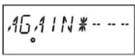
When the display shows "NEW * - - -", enter the new pass code by pressing the number buttons.
When the display shows "AGAIN * - - -", re-enter the new pass code to confirm and the new pass code will be stored.


From this point, whenever the lock button is pressed during normal operation, this pass code will be needed to unlock the panel.
ID setting
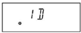
RS485 connection has been included on the DP-8 for digital remote control of the switching schedule. When controlled via RS-485 connection, each DP-8 will have an individually addressable ID.
The ID setting menu enables the ID number of the DP-8 to be stored from ID01 to ID99.
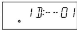
From the settings menu, step through the options until "ID" is displayed and then press "Enter" Set the ID number using the +/- buttons (8) and press Enter again to confirm.
Bypass

The Bypass setting enables the user to select which channels are set to always on, bypassing manual or timer control.
From the settings menu, step through the options until "BYPASS" is displayed and then press "Enter" Set the channel buttons (6) on for channels which are to be always on, regardless of timer or manual control.

Press Enter again to store the setting.
Learning

The Learning setting allows a preset on or off switching sequence to be stored by mimicking button presses on the front panel.
From the settings menu, step through the options until "LEARNING" is displayed and then press "Enter" The ON and OFF symbols will flash in the display.
Press the On or Off buttons to select which sequence is to be programmed.
Press Enter again and a timer will appear with all zeros in the display, waiting for a button to be pressed.

Press the channel buttons to record a sequence of up to 16 switching events and the timer will start automatically and follow the sequence in real time.
The program will be saved either when 16 events have been entered or the Enter button is pressed.

Exit the menu and press the On or Off button to trigger the relative stored sequence.
Initialization

To reset the DP-8 to initial factory settings, in the settings menu, step through the options until "INIT" is displayed and press "Enter". The display will show "INIT N", where "N" denotes "No". Use the +/- buttons (8) to set to yes and press Enter. All settings will be set to initial factory values and the Key lock will be set on with the initial pass code 1 - 2 - 3 - 4.
Specifications
| Power supply | 110-230Vac, 50/60Hz (hard-wired) |
| Current max. | 32A total |
| Contact rating | 10A max. for any output |
| Time setting | Day(s), hours, minutes, seconds |
| Internal programs | 99 schedule scenes, auto power sequence |
| Outputs | 8 x IEC power outlets |
| Connections | USB port, RS485, 12Vdc out, remote, GND, Status |
| Dimensions | 482 x 250 x 44mm |
| Weight | 3.0kg |