P4100P - Lawn mower HYUNDAI - Free user manual and instructions
Find the device manual for free P4100P HYUNDAI in PDF.

| Product Type | Petrol Lawn Mower |
| Brand | Hyundai |
| Model | P4100P |
| Engine Displacement | 196 cc |
| Power Source | Petrol (4-stroke) |
| Cutting Width | 46 cm (18 inches) |
| Cutting Height Adjustment | 6 positions, 25-75 mm |
| Grass Collector Capacity | 60 litres |
| Drive Type | Self-propelled (rear wheel drive) |
| Mulching Capability | Yes (mulching plug included) |
| Starting System | Recoil start |
| Handle Type | Foldable, adjustable height |
| Wheel Size | Front: 7 inches, Rear: 10 inches |
| Dimensions (L x W x H) | 145 x 55 x 105 cm |
| Weight | 32 kg |
| Fuel Tank Capacity | 1.0 litre |
| Oil Capacity | 0.5 litre |
| Maintenance | Regular oil change, blade sharpening, air filter cleaning |
| Safety Features | Operator presence control, blade brake, engine stop lever |
| Spare Parts Availability | Blades, air filters, spark plugs, belts available online |
| Recommended Use | Medium to large lawns, up to 1000 m² |
Frequently Asked Questions - P4100P HYUNDAI
User questions about P4100P HYUNDAI
0 question about this device. Answer the ones you know or ask your own.
Ask a new question about this device
Download the instructions for your Lawn mower in PDF format for free! Find your manual P4100P - HYUNDAI and take your electronic device back in hand. On this page are published all the documents necessary for the use of your device. P4100P by HYUNDAI.
USER MANUAL P4100P HYUNDAI
P1 Petrol Lawn Mower
P4100P P4600SP P5100SPE
User Manual
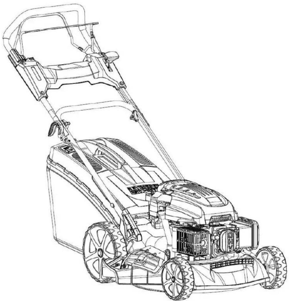
natural_image
Line drawing of a lawn mower with visible blades and handle (no text or symbols)INDEX
| CONTENTS | PAGE NO.S | |
| 1 | SAFETY | 3-8 |
| 2 | PART LOCATIONS | 9 |
| 3 | QUICK START GUIDE P4100P & P4600SP | 10 – 14 |
| 4 | QUICK START GUIDE P5100SPE | 15 - 20 |
| 5 | STARTING PROCEDURE | 21 – 24 |
| 6 | STOPPING PROCEDURE | 25 |
| 7 | OPERATING INSTRUCTIONS | 26 - 28 |
| 8 | MAINTENANCE | 29 – 39 |
| 9 | STORAGE, WINTERISATION & TRANSPORTATION | 39 – 40 |
| 10 | TROUBLESHOOTING | 41 |
| 11 | SPECIFICATION | 42 |
| 12 | RECYCLING & PRODUCT DISPOSAL | 43 |
| 13 | DECLARATION OF CONFORMITY | 44 |
| 14 | CONTACT DETAILS | 45 |
| 15 | WARRANTY | 45 |
| 16 | MANUAL UPDATES | 45 |
1. SAFETY
1.1 General Safety Notes.
1.2 The operator of the machine is responsible for, and has a duty of care in making sure that the machine is operated safely and in accordance with the instructions in this user manual. Keep the manual safe and pass it on if the machine is loaned or sold to another user.
1.3 Please note the following safety points.
1.4 The machine should never be left it in a condition which would allow an untrained or unauthorised person/s to operate this machine.
1.5 All due care and diligence should be taken by the operator for the safety of and with regard to those around whilst using the machine.
1.6 Some or all of the following - warning signs, symbols and/or PPE pictograms may appear throughout this manual. You MUST adhere to their warnings. Failure to do so may result in personal injury to yourself or those around you.

DANGER
Indicates a hazard, which, if not avoided, could result in serious injury or death.

WARNING
Indicates a hazard, which, if not avoided, could result in serious injury.

CAUTION
Indicates a hazard which, if not avoided, might result in minor or moderate injury.

NOTE
Indicates a situation that could easily result in equipment damage.
READ and keep the manual safe and pass it on if the machine is loaned or sold to another user.
You MUST fully understand all instructions to ensure you use and operate the machine safely.
Appropriate Personal Protective Equipment (PPE), MUST be worn at all times when operating or repairing the machine.


1.10 Carbon Monoxide (where applicable).

text_image
DANGER! BREATHING IN CARBON MONOXIDE FUMES CAN KILL YOU! To help protect against CO poisoning install a Carbon Monoxide detector. NEVER use Petrol/Diesel powered equipment inside, especially a home, garage, tent, camper-van, caravan, motorhome or boat. EVEN if doors, windows, vents and hatches are open. Only use OUTDOORS and as far away from doors, windows, vents and open hatches as possible to prevent inhaling fumes. READING MANUAL BEFORE USE WILL HELP AVOID OTHER MACHINE HAZARDS.1.11 Carbon monoxide is a colourless and odourless gas. Inhaling this gas can cause death as well as serious long term health problems such as brain damage.
1.12 The symptoms of carbon monoxide poisoning can include but are not limited to the following; Headaches, dizziness, nausea, breathlessness, collapsing or loss of consciousness.
1.13 Carbon monoxide poisoning symptoms are similar to flue, food poisoning, viral infections and simply tiredness. It is quite common for people to mistake this very dangerous poisoning for something else.
1.14 To avoid carbon monoxide poisoning DO NOT use Petrol/Diesel powered equipment inside any of the following; Home, garage, tent, camper van, mobile home, caravan or boat. This is not exhaustive and if you are in any doubt contact your dealer.
1.15 If you think you have or someone around you has been affected by carbon monoxide poisoning;
1.16 Get them fresh air immediately, by leaving the affected area or by opening doors and windows. If safe and practical to do so make sure that the machine is turned off.
DO NOT enter a room you suspect of having carbon monoxide present – instead call the emergency services.
1.17 Contact a Doctor immediately or go to Hospital – let them know that you suspect carbon monoxide poisoning.
1.18 DO NOT use in an enclosed area or moving vehicle.
1.20 General Fuel Safety (where applicable).

CAUTION
ALL FUELS ARE FLAMABLE
1.21 Fire Hazard – keep fuel away from all sources of ignition for example heaters. Lamps, sparks from grinding or welding.
1.22 DO NOT carry out hot work on tanks that have contained fuel.
1.23 ALWAYS keep the work area tidy.
1.24 ALWAYS clean up spills promptly using absorbent granules and a lidded bin.
1.25 ALWAYS dispose of waste fuels correctly.
1.30 Fueling/De-fueling (where applicable).
CAUTION ALL FUELS ARE FLAMABLE
1.31 ALWAYS fuel and defuel in a well ventilated area outside of buildings.
1.32 ALWAYS wear correct, suitable and fit for purpose Personal Protective Equipment (PPE), suggested items are but not limited to safety gloves, overalls.

text_image
HAND PROTECTION MUST BE WORN PROTECTIVE CLOTHING MUST BE WORN1.33 When fueling/de-fueling ALWAYS avoid inhaling fumes.
1.34 When de-fueling ALWAYS use a proper fuel retriever.
1.35 ALWAYS carry fuel in the correct and clearly marked container.
1.40 Electrical Safety (where applicable).
1.41 Electricity can kill – NEVER work on LIVE/ENERGISED equipment.
1.42 Prior to carrying out any maintenance work you MUST identify electrical isolation methods and isolate all electrical supplies.
1.43 Prior to use and with all electrical supplies isolated, you MUST check all electrical cables, plugs and connectors for the following;
1.44 Are intact and have no signs of damage, to include but not limited to bare wires, chaffing, cuts and loose wiring.
1.45 If there are any signs of damage, the damaged item MUST be taken out of service until the damage has been repaired by an electrically competent person.
1.46 All trailing cables should be routed so as not to cause any kind of trip hazard.
1.47 NEVER work on or near electricity with wet hands, wet clothing and wet gloves.

risk of electric shock
1.50 Batteries (where present).
1.51 Batteries present a risk if they become damaged by the possible leaking of electrolyte. This electrolyte is an acid and can cause serious burn injuries. Care should be taken when working on or near them. NOTE the electrolyte may be in a liquid or gel form.
1.52 Should you come in to contact with electrolyte you should;
1.53 Remove all clothing contaminated with electrolyte. If you cannot remove then saturate them in water.
1.54 Get medical assistance as soon as possible. You must advise the medical staff of the type of acid.
1.55 Lead/acid battery = dilute sulphuric acid.
1.56 Nickel/cadmium = potassium hydroxide alkali electrolyte.
1.57 Use fresh running water to wash off excess electrolyte, continue this until medical assistance arrives. Make sure that you do not was the electrolyte to another part of your body or face.
1.58 If electrolyte comes in to contact with Eyes the electrolyte needs to be immediately washed away with large amounts of water. Make sure that you do not wash the electrolyte to another part of your face or body.
1.59 Gasses from charging batteries are highly flammable and great care should be taken to charge in well ventilated areas.
1.59.1 There is an explosion risk if the battery terminals are short circuited, when connecting/disconnecting ALWAYS exercise great care so that the terminals or battery leads are NOT allowed to touch and cause a spark. ALWAYS use suitable insulated tools.
1.60 Vibrations (where applicable).
1.61 Prolonged use of hand held (operated) machines will cause the user to feel the effects of/from vibrations. These vibrations can lead to white finger (Raynaud's phenomenon) or carpal tunnel syndrome. This condition reduces the ability of the hand to feel and regulate temperature, causing numbness and heat sensations and may cause never damage and circulatory tissue death.
1.62 Not all factors that lead to white finger disease are known, but cold weather, smoking and other diseases that affect blood vessels and blood circulation as well as large and long-lasting impact of shocks are considered factors in the formation of white finger. Note the following to reduce the risk of white finger and carpal tunnel syndrome;
1.63 Wear gloves and keep your hands warm.
1.64 Take regular breaks.
1.65 All of the above precautions may help reduce the risk of white finger disease but not rule out the carpal tunnel syndrome. Long-term and regular users are therefore
recommended to observe the condition of your hands and fingers. Seek medical attention immediately if any of the above symptoms should occur.
1.70 Noise (where applicable).
1.71 The operating noise of the machine can damage your hearing. Wear hearing protection such as earplugs or ear defenders to protect your hearing. Long-term and regular users are advised to have hearing checked regularly. Be especially vigilant and cautious when hearing ear protection because your ability to hear alarm warnings will be reduced.
1.72 Noise emissions for this equipment is unavoidable. Carry out noisy work at approved times and for certain periods. Limit the working time to a minimum. For your personal protection and protection of people working nearby it is also advisable for them to wear hearing protection.
1.73 See Certificate of Conformity section for Outdoor Noise declaration of conformity.
MACHINE SPECIFIC SAFETY
1.80 General Machine Safety.
1.81 Read the owner's manual carefully to understand how to operate this machine properly.
1.82 You should NEVER use the machine when;
1.83 Wearing loose clothing, barefoot or sandals.
1.84 Under the influence of drink or drugs or as a result of having taken medication for cold or flu, or any other times when a possibility exists that your judgement might be impaired or that you might not be able to operate the machine properly and in a safe manner.
1.85 Suffering from exhaustion or lack of sleep.
1.86 When the ground is slippery or when other conditions exist which might make it not possible to maintain a steady posture.
1.87 At night, at times of heavy fog, or at any other times when your field of vision might be limited and it would be difficult to gain a clear view of the area.
1.88 During rain storms, lighting storms, at times of strong or gale force winds, or at any other times when the weather conditions might make it unsafe to use this product.
1.89 NEVER run the engine indoors. The exhaust gasses contain harmful carbon monoxide.
1.90 When using this machine for the first time and before actual work, you MUST learn how to handle the machine from an experienced or skilled person.
1.91 Limit the amount of time using the machine continuously to somewhere around 10 minutes per session and take 10 to 20 minutes of rest between sessions. Also try to keep the total amount of work in a single day limited to 2 hours or less.
1.92 NEVER allow children or anyone unable to fully understand the directions given in this manual to operate this product.
1.93 Make sure you keep this manual handy so you may refer to it whenever questions arise and ensure you pass this manual on if the machine is loaned or sold.
1.94 Correct Personal Protective Equipment (PPE) MUST be worn at all times when operating or repairing this machine. This should include but is not limited to;


1.95 Do not use this machine inside a confined space such as but not limited to a vehicle, house, garage, container, boat or building. Only use outside in a well ventilate area.
1.96 For air cooling a minimum of 1m is required all around the machine. Maximum ambient temperature 40 degrees Celsius.
1.97 Fire risk- Fuel can expand and overflow in a hot environment or moving vehicle. Explosion risk- LPG/ Petrol can leak and the vapour is heavier than air. Never store in confined spaces especially in a boat where the vapour/has will accumulate in the hull and create a high risk of explosion.
1.98 Carbon monoxide poisoning risk- Never run an engine in a confined space or poorly ventilated area. Keep machine away from windows to prevent fumes entering the internal space. Carbon monoxide is produced by the engine and contained in the exhaust fumes. You cannot see it or smell it and it can kill you in minutes.
1.99 Never use inside a confined space with an exhaust extension. If the exhaust extension fails the escaping exhaust gases could kill you.
2. PART LOCATIONS
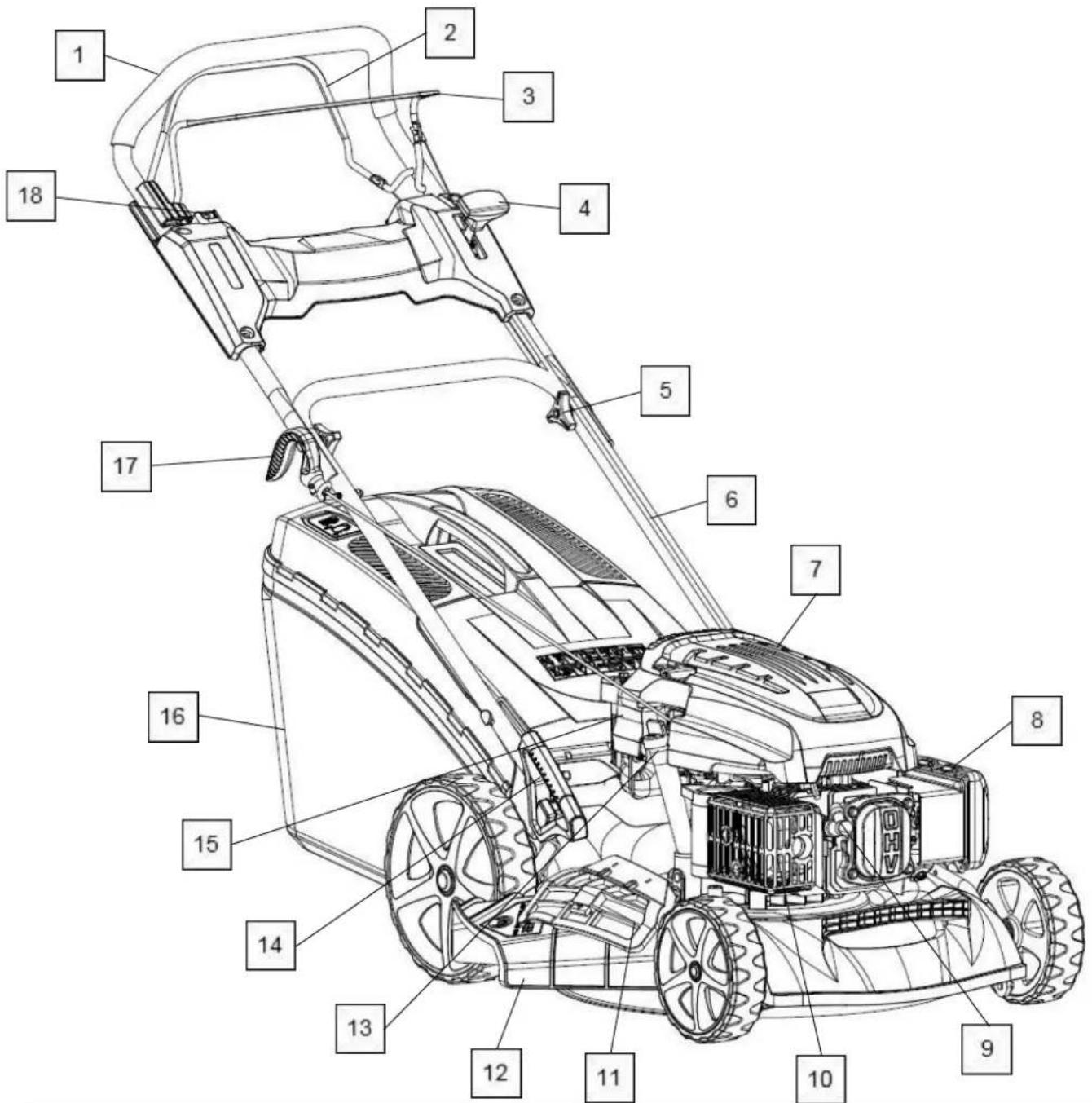
text_image
Technical diagram of a lawn mower with numbered parts for identification| 1 | Upper Handle | 10 | Exhaust |
| 2 | Self-Propelled Drive Lever* | 11 | Side Discharge Cover* |
| 3 | Operator Presence Control Lever | 12 | Side Discharge Chute* |
| 4 | Throttle Lever* | 13 | Oil Filler/Dipstick |
| 5 | Handle Quick Release | 14 | Wheel Height Adjustment Lever |
| 6 | Lower Handle | 15 | Battery* |
| 7 | Fuel Filler Cap | 16 | Grass Collector |
| 8 | Air Filter | 17 | Recoil Start Handle |
| 9 | Spark Plug | 18 | Push Button Electric Start* |
*P5100SPE Only
3. QUICK START GUIDE P4100P & P4600SP
WARNING
This guide is meant to serve as a quick reference for operating your P1 lawn mower.
We advise reading the manual in full before operation.
NOTE
This lawnmower is shipped without oil or petrol.
You MUST ensure the correct oil and fuel is used BEFORE use
Oil: Semi-Synthetic SAE 15W40 Engine Oil.
Oil Capacity P4100P: 400ml
Oil Capacity P4600SP: 600ml
Fuel: Unleaded Petrol
Fuel Capacity P4100P: 1000ml
Fuel Capacity P4600SP: 1100ml
Fuel Capacity P5100SPE:
ASSEMBLY
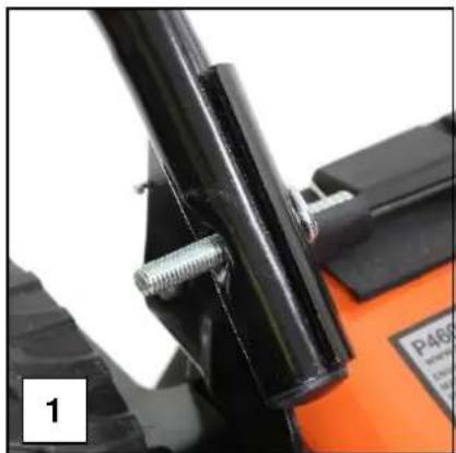
2.0 Attach the lower handle to the deck of the mower by inserting the bolt (1).
2.1 Place the plastic over the bolt washer ensuring the curve of the washer sits on the curve on the handle bar (2).
2.2 Secure in place using the large locking wheel (3).
natural_image
Close-up of a mechanical component with black metal parts and threaded fasteners, no visible text or symbols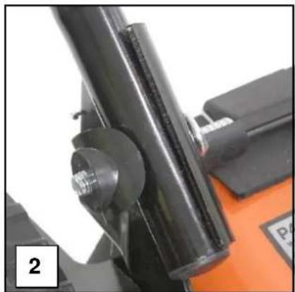
natural_image
Close-up of a mechanical component with a black cylindrical shaft and threaded bolt, mounted on an orange base (no visible text or symbols)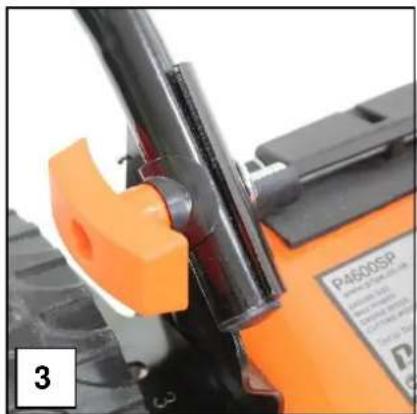
natural_image
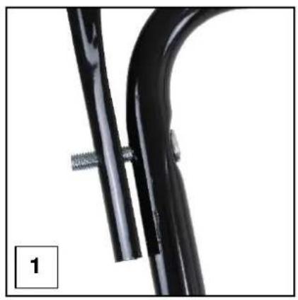
Close-up of a mechanical component with orange clamping mechanism and black handle (no visible text or symbols)2.3 Attach the upper handle to the lower handle by inserting the bolt (1).
2.4 Place the plastic over the bolt washer ensuring the curve of the washer sits on the curve on the handle bar (2).
2.5 Secure in place using the large locking wheel (3).
natural_image
Close-up of a black curved metal bracket with a small metallic fastener attached (no text or symbols visible)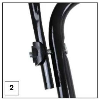
natural_image
Close-up of a black bicycle support structure with metal fasteners (no text or symbols visible)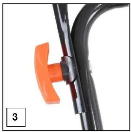
natural_image
Close-up of a black metal tool with an orange handle, no visible text or symbols
natural_image
Close-up of an orange lawn mower with black levers and control panel (no visible text or symbols)2.6 Lift the rear discharge flap to expose the grass bag support bar (1).
2.7 Using the hooks on the grass bag, hook the grass bag over the bar at the rear of the lawn mower (2).
2.8 Lower the rear discharge flap until it rests on the grass bag (3).

natural_image
Close-up of an orange manual lawn mower with visible wheels and a black cover (no text or symbols)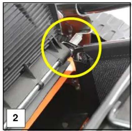
natural_image
Close-up of a mechanical assembly with a yellow circle highlighting a component, no visible text or symbols
natural_image
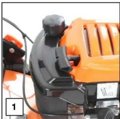
Electric lawn mower with a black and orange body, labeled 'PE' on the cover (no additional text or symbols visible)2.9 Gently pull the recoil start handle (1) up to the recoil retaining loop (2).

natural_image
Close-up of an orange and black industrial machine component (no visible text or symbols)
natural_image
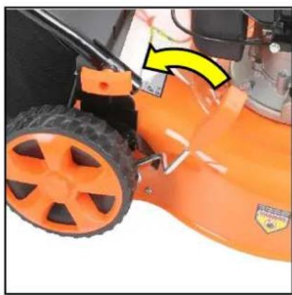
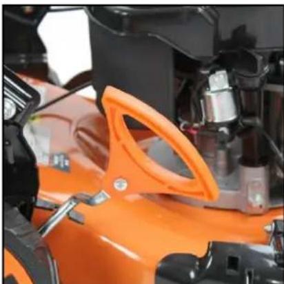
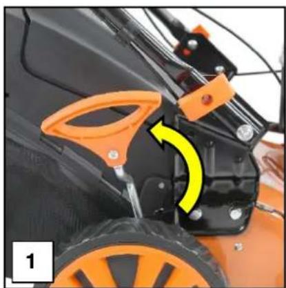
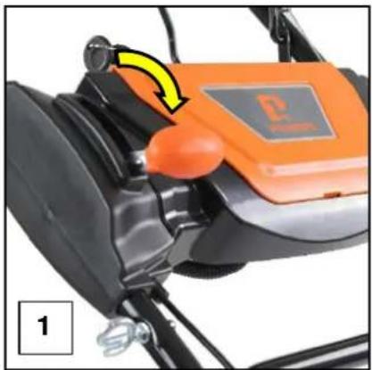
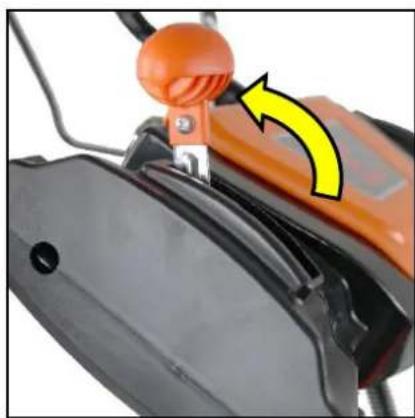
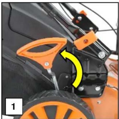
Close-up of a black mechanical clip securing a piece of cable, with an orange clamp attached (no text or symbols visible)2.10 Set the cutting height to maximum.
natural_image
Close-up of an orange lawn mower with a yellow arrow indicating motion direction (no text or symbols visible)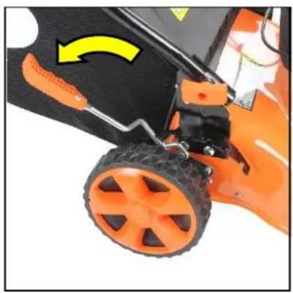
natural_image
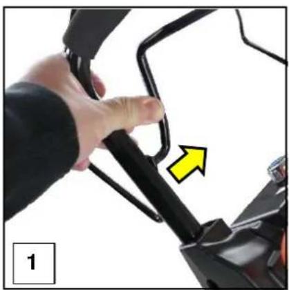
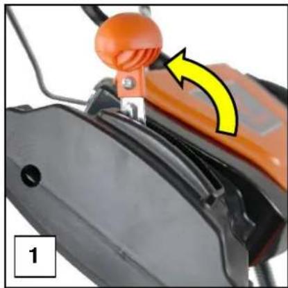
Close-up of an orange lawn mower with a yellow arrow indicating rotational motion (no text or symbols visible)CABLE ATTACHEMENT
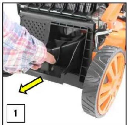
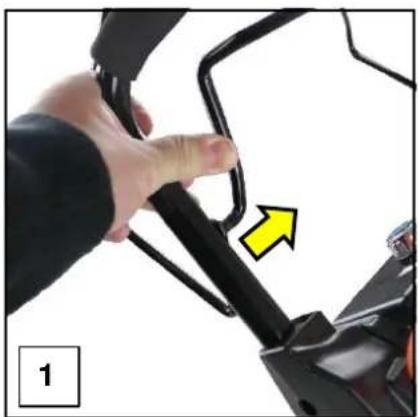
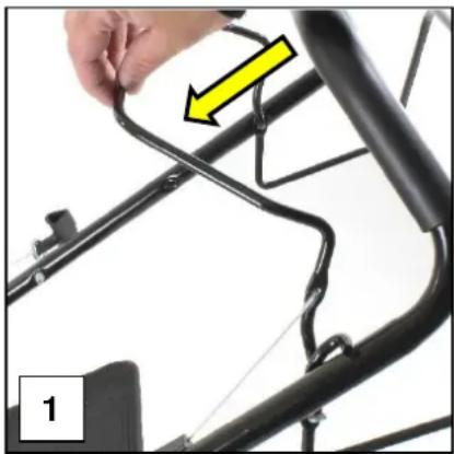
2.11 Gently push the handle free from its locating hole on the main handlebar (1).
2.12 Insert the end of the cable in to the location hole on the lever (2).
natural_image
Close-up of a hand adjusting a black bicycle handle with a yellow arrow pointing to the handle (no text or symbols visible)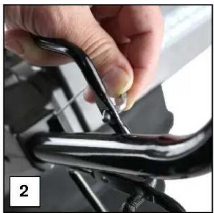
natural_image
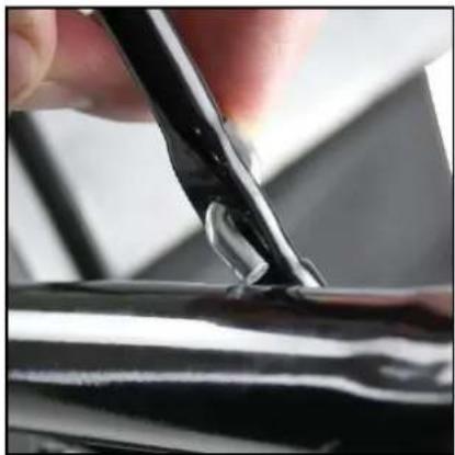
Close-up of a hand using a tool to adjust or install a metallic mechanical component (no visible text or symbols)2.13 Follow the curve of the cable until the cable lies flat in the handle (1).
2.14 Refit the lever back into its location hole on the main handlebar (2).
2.15 Check the cable lies flat and has not snagged on any other part of the lawn mower.

natural_image
Close-up of a hand using a tool to trim a black plastic object on a surface (no text or symbols visible)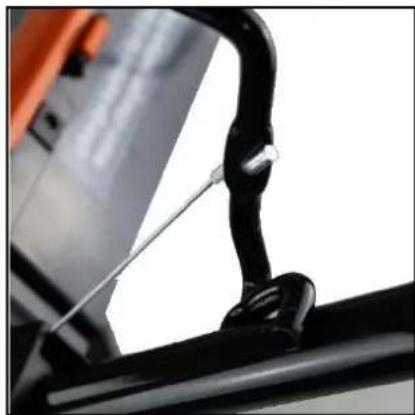
natural_image
Close-up of a black bicycle handle with metal clip and cable attachment (no visible text or symbols)ADDING OIL
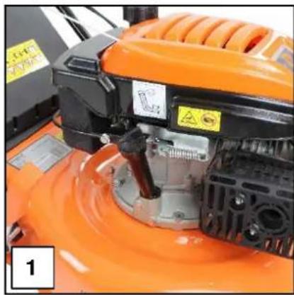
2.16 Place the lawn mower on a flat level surface (1).
2.17 Unscrew and remove the dipstick (2).
natural_image
Close-up of an orange lawn mower with visible mechanical components and warning labels (no readable text or symbols)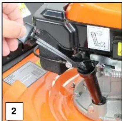
natural_image
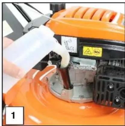
Close-up of a hand using a mechanical tool to adjust components on an orange industrial machine (no visible text or symbols)2.18 Slowly fill with approx. 600ml of Semi-Synthetic SAE15W40 engine oil (1) to the upper level mark on the dipstick (2).
2.19 DO NOT OVERFILL stop occasionally to check the oil level.
2.20 Once full, refit the dipstick securely.
2.21 If you do overfill, you can remove some oil by gently tiling the machine on its side and pouring the excess oil into a suitable container.
natural_image
Close-up of an orange industrial machine with a white spray bottle and mechanical components (no visible text or symbols)
natural_image
Close-up of a vertical pole with a yellow arrow pointing to the right side, labeled '2' in the corner (no text or symbols on the pole itself)ADDING FUEL
CAUTION
ALL FUELS ARE HIGHL FLAMMABLE
ALWAYS fuel and defuel in a well ventilated area outside of buildings and away from any possible sources of ignition.
ALWAYS wear correct, suitable and fit for purpose Personal Protective Equipment (PPE). Suggested items are but not limited to, safety gloves, eye protection and overalls.
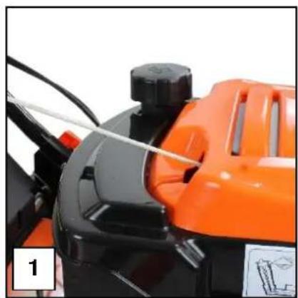
2.22 Place the lawn mower on a flat level surface (1).
2.23 Remove the fuel filler cap (2) and slowly fill with unleaded petrol (3).
2.24 DO NOT fill the tank right to the top but leave a 25mm gap between the top of the fuel tank and the fuel filler cap.
2.25 Once full, refit the fuel filler cap securely.
natural_image
Close-up of an orange and black lawn mower with a handle and control panel (no visible text or symbols)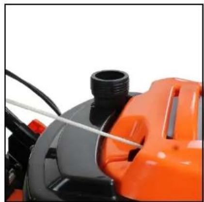
natural_image
Close-up of a black and orange industrial machine component with hoses and tubing (no visible text or symbols)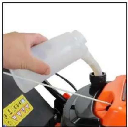
natural_image
Hand pouring liquid into a car engine component with orange valve (no visible text or symbols)4. QUICK START GUIDE P5100SPE
WARNING
This guide is meant to serve as a quick reference for operating you P1 lawn mower.
We advise reading the manual in full before operation.
NOTE
This lawnmower is shipped without oil or petrol.
You MUST ensure the correct oil and fuel is used BEFORE use
Oil: Semi-Synthetic SAE 15W40 Engine Oil.
Oil Capacity: 600ml
Fuel: Unleaded Petrol
Fuel Capacity: 1100ml
ASSEMBLY
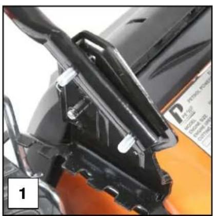
3.0 Attach the lower handle to the deck of the mower by inserting the 2 bolts (1). NOTE You can select 2 different handle heights.
3.1 Place the washers over the bolts (2).
3.2 Secure in place using the large locking wheel and the nut (3).
natural_image
Close-up of a black mechanical component with attached brackets and mounting holes, no visible text or symbols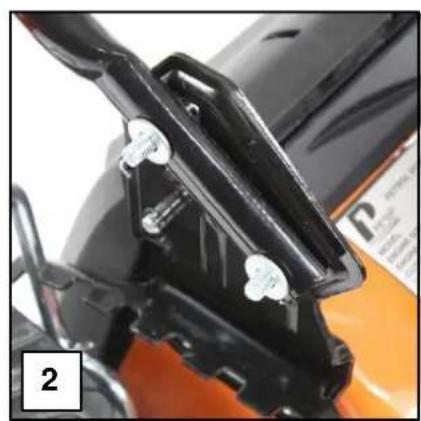
natural_image
Close-up of a black motorcycle front bumper with metal fasteners and orange background (no visible text or symbols)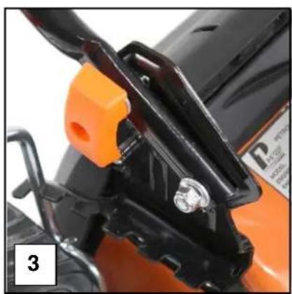
natural_image
Close-up of an orange motorcycle's front wheel and side-mounted bracket (no visible text or symbols)3.3 Attach the upper handle to the lower handle (1).
3.4 Mount the centre panel between the handlebars and fix using the screws provided (2).
3.5 Gently pull the recoil start handle up to the recoil retaining loop (3).
3.6 Insert the two central mounting panel tabs into tinto the slots provided on the upper handlebar (1).
3.7 Place the central ignition panel so it rests on the 2 mounting tabs (2).
3.8 Line up the screw holes on the ignition panel with the screw holes on the two central mounting panel tabs and secure in place using the screws provided (3).

natural_image
Close-up of a metallic mechanical component with mounting holes and a small rectangular bracket (no visible text or symbols)
natural_image
Close-up of a hand operating a black industrial machine with orange control knobs, mounted on a metal frame (no visible text or symbols)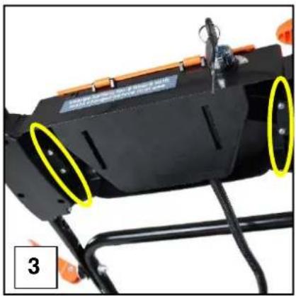
natural_image
Close-up of a black industrial machine with yellow circular annotations highlighting features, mounted on a metal frame (no visible text or symbols)3.9 Lift the rear discharge flap and remove the mulching plug if installed. (1).
3.10 Using the hooks on the grass bag, hook the grass bag over the bar at the rear of the lawn mower (2).
3.11 Lower the rear discharge flap until it rests on the grass bag (3).
natural_image
Close-up of a person using a lawn mower to adjust the blade of an orange lawn mower (no text or symbols visible)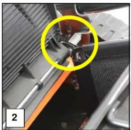
natural_image
Close-up of a mechanical assembly with a yellow circle highlighting a component, no visible text or symbols
natural_image
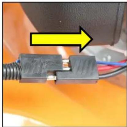
Close-up of a black lawn mower with orange wheels and a white 'P' logo on the cover (no text or symbols on the main subject)3.12 Connect the battery and ignition to the engine by tracking the cable from the centre ignition panel and plugging it into the plug on the main lawn mower engine.
natural_image
Close-up of a black electrical connector with wires and a yellow arrow pointing to it (no text or symbols visible)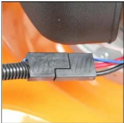
natural_image
Close-up of a black plastic connector with blue and red wires, mounted on an orange vehicle (no visible text or symbols)3.13 Gently pull the recoil start handle (1) up to the recoil handle retaining loop (2).
natural_image
Close-up of an orange industrial machine with black and white components, no visible text or symbols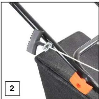
natural_image
Close-up of a black tool securing an orange clip into a black box (no text or symbols visible)3.14 Set the cutting height to maximum.
natural_image
Close-up of an orange industrial vehicle's wheel assembly with visible components and no text or symbols
natural_image
Close-up of a black lawn mower with orange handle and yellow arrow indicating a component (no text or symbols visible)CABLE ATTACHEMENT
3.13 Gently push the handle free from its locating hole on the main handlebar (1).
3.14 Insert the end of the cable in to the location hole on the lever (2).
natural_image
Close-up of a hand adjusting a black mechanical bracket with a yellow arrow pointing to the handle (no text or symbols visible)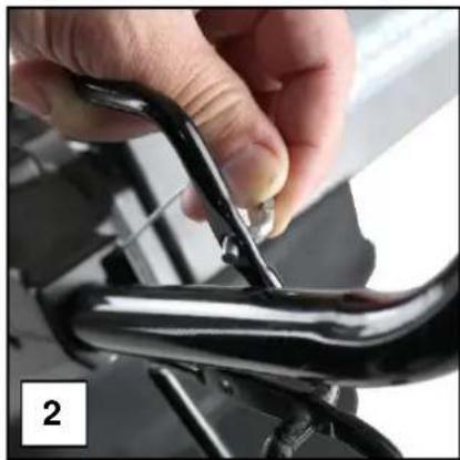
natural_image
Close-up of hands adjusting a black metal bracket with a small metallic clip (no text or symbols visible)3.15 Follow the curve of the cable until the cable lies flat in the handle (1).
3.16 Refit the lever back into its location hole on the main handlebar (2).
3.17 Check the cable lies flat and has not snagged on any other part of the lawn mower.
natural_image
Close-up of a hand using a tool to apply material on a black surface (no visible text or symbols)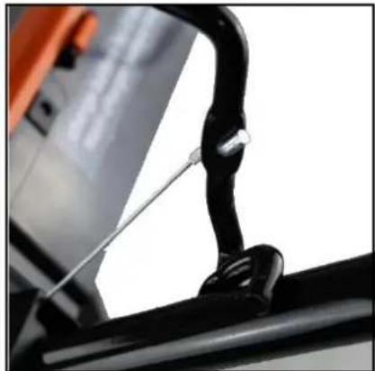
natural_image
Close-up of a black bicycle handle with metal clip and cable attachment (no visible text or symbols)ADDING OIL
3.17 Place the lawn mower on a flat level surface (1).
3.18 Unscrew and remove the dipstick (2).
natural_image
Close-up of an orange lawn mower with visible mechanical components and warning labels (no readable text or symbols)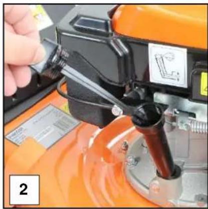
natural_image
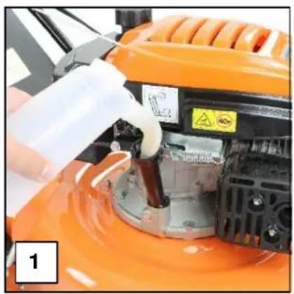
Close-up of a hand pouring liquid into an orange industrial machine component (no visible text or symbols)3.19 Slowly fill with approx. 600ml of Semi-Synthetic SAE15W40 engine oil (1) to the upper level mark on the dipstick (2).
3.20 DO NOT OVERFILL stop occasionally to check the oil level.
3.21 Once full, refit the dipstick securely.
3.22 If you do overfill, you can remove some oil by gently tiling the machine on its side and pouring the excess oil into a suitable container.
natural_image
Close-up of a hand pouring liquid into an orange industrial machine component (no visible text or symbols)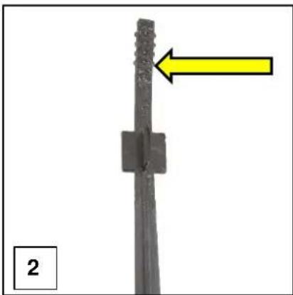
natural_image
Close-up of a vertical pole with a textured surface and a yellow arrow pointing to it, labeled '2' (no text or symbols on the pole itself)CAUTION
ALL FUELS ARE HIGHL FLAMMABLE
ALWAYS fuel and defuel in a well ventilated area outside of buildings and away from any possible sources of ignition.
ALWAYS wear correct, suitable and fit for purpose Personal Protective Equipment (PPE). Suggested items are but not limited to, safety gloves, eye protection and overalls.
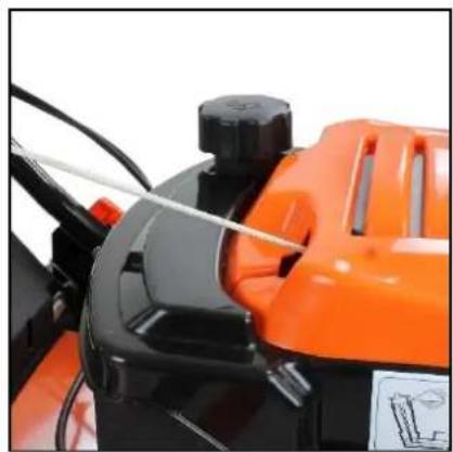
3.23 Place the lawn mower on a flat level surface (1).
3.24 Remove the fuel filler cap (2) and slowly fill with unleaded petrol (3).
3.25 DO NOT fill the tank right to the top but leave a 25mm gap between the top of the fuel tank and the fuel filler cap.
3.26 Once full, refit the fuel filler cap securely.
natural_image
Close-up of an orange and black lawn mower with a handle and control panel (no visible text or symbols)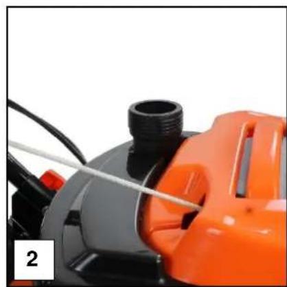
natural_image
Close-up of a mechanical device with black and orange components, no visible text or symbols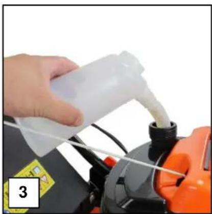
natural_image
Person pouring liquid from a plastic bottle into a car engine component (no visible text or symbols)5. STARTING PROCEDURE

This lawnmower is shipped without oil or petrol.
You MUST ensure the correct oil and fuel is used BEFORE use
Oil: Semi-Synthetic SAE 15W40 Engine Oil.
Oil Capacity: 600ml
Fuel: Unleaded Petrol
Fuel Capacity P4000P & P4600SP: 1000ml
Fuel Capacity P5100SPE: 1100ml
COLD RECOIL START – ALL MODELS
4.0 Make sure the blade is free of long grass and the cutting height is set to maximum (1).
4.1 Pump the primer bulb 5 times (2).
natural_image
Close-up of a lawn mower with orange handle and yellow directional arrow indicating rotation (no text or symbols)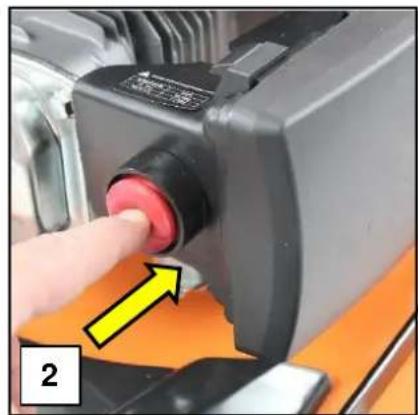
natural_image
Close-up of a hand pressing a red button on a mechanical component, with a yellow arrow pointing to the button (no text or symbols visible)4.2 P5100SPE ONLY: Push the choke lever fully forward (1).
4.3 Pull the Operator Presence Control (OPC) lever (2) towards the main handle.
natural_image
Close-up of a mechanical device with orange and black components, no visible text or symbols
natural_image
Person holding a black bicycle handle with a yellow arrow pointing to the handle (no text or symbols visible)4.4 Gently pull the recoil start handle until you feel resistance (1).
4.5 Then pull the handle swiftly, until the lawn mower starts (2).

natural_image
Close-up of a hand using a tool to lift a black mechanical component (no visible text or symbols)
natural_image
Close-up of a robotic arm with a yellow arrow pointing to a component, no visible text or symbols4.6 P5100SPE ONLY: Allow to run for 15 seconds, then slowly move the choke lever (1) back towards the run position.
natural_image
Close-up of an orange manual lawn brush applying material to a black workpiece, with a yellow arrow indicating motion direction (no text or symbols)WARM RECOIL START – ALL MODELS
4.6 Make sure the blade is free of long grass and the cutting height is set to maximum (1).
4.7 P5100SPE ONLY: Make sure the choke lever is in the closed position (2).

natural_image
Close-up of a lawn mower with orange handle and yellow directional arrow indicating rotation (no text or symbols)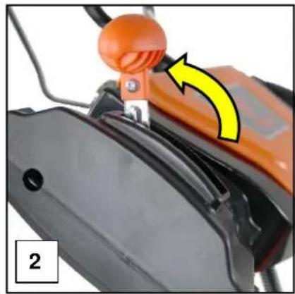
natural_image
Close-up of an orange manual lawn brush applying material to a black mechanical component, with a yellow arrow indicating motion direction (no text or symbols)4.8 Gently pull the recoil start handle until you feel resistance (1).
4.9 Then pull the handle swiftly, until the lawn mower starts (2).

natural_image
Close-up of a hand using a tool to lift a black mechanical component (no visible text or symbols)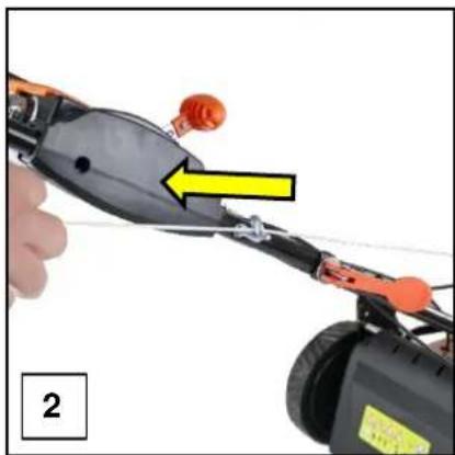
natural_image
Close-up of a robotic arm with a yellow arrow pointing to a component, no visible text or symbolsCOLD ELECTRIC START - P5100SPE ONLY
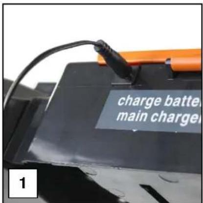
4.10 Charge the battery for 5 hours before first use and then after every 10 uses on average (1).
4.10 Make sure the blade is free of long grass and the cutting height is set to maximum (1).
4.11 Pump the primer bulb 5 times (2).
text_image
charge battery main charge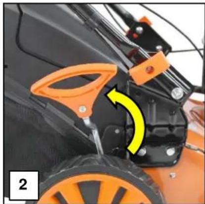
natural_image
Close-up of a small orange lawn mower with a yellow arrow indicating rotational motion (no text or symbols visible)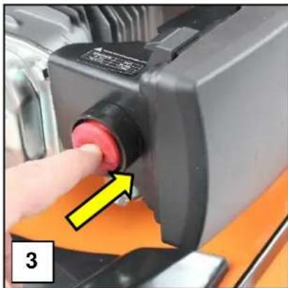
natural_image
Close-up of a hand pressing a red button on a mechanical device (no visible text or symbols)4.12 Push the choke lever fully forward (1).
4.13 Pull the Operator Presence Control (OPC) lever (2) towards the main handle.

natural_image
Close-up of a mechanical device with orange and black components, no visible text or symbols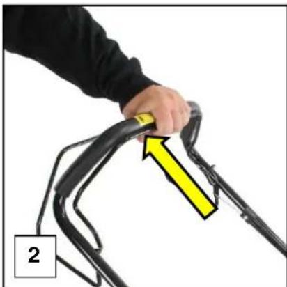
natural_image
Person holding a black bicycle handle with a yellow arrow pointing to the handle (no text or symbols visible)4.14 Push the start button.
4.15 DO NOT keep the button pressed for longer than 5 seconds.
4.16 Once the lawn mower starts, release the start button.
4.17 If the lawn mower fails to start after 5 seconds, release the start button, wait 30 seconds then try again.
4.18 Allow to run for 15 seconds, then slowly move the choke lever (1) back towards the run position.
natural_image
Close-up of an orange and black manual lawn brush with a yellow arrow indicating motion (no text or symbols visible)WARM ELECTRIC START – P5100SPE ONLY
4.19 Make sure the blade is free of long grass and the cutting height is set to maximum (1).
4.20 Pull the Operator Presence Control (OPC) lever (2) towards the main handle.
4.21 Make sure the choke lever is in the closed position (3).
natural_image
Close-up of a lawn mower with orange handle and yellow directional arrow indicating motion (no text or symbols)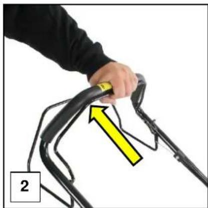
natural_image
Person holding a black bicycle handle with a yellow arrow indicating motion direction (no text or symbols)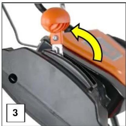
natural_image
Close-up of an orange lawn mower with a yellow arrow indicating motion direction (no text or symbols)4.22 Push the start button.
4.23 DO NOT hold it in the start position for longer than 5 seconds.
4.24 Once the lawn mower starts, release the start button.
4.25 If the lawn mower fails to start after 5 seconds, release the button, wait 30 seconds and then try again.
6. STOPPING PROCEDURE

CAUTION
The engine and exhaust will remain hot for a while after use.
Ensure the engine and exhaust have cooled before carrying out any maintenance or storing the machine.
5.0 Before stopping the machine, you must allow the engine to idle under no load for 30 seconds.
5.1 Release the Operator Presence Control (OPC) lever (1) and the engine will stop.
5.2 P5100SPE ONLY: Turn the ignition key to the OFF position.
natural_image
Close-up of a bicycle track with a hand adjusting the cable, showing a yellow arrow and label '1' (no text or symbols on the diagram itself)7. OPERATING INSTRUCTIONS
NOTE
Not all features are available on every lawn mower.
Images may vary depending on model.
6.0 Always use the lawn mower with the grass catcher or rear deflector in position.
6.1 Stop the engine before emptying the grass catcher or before you change the cutting height.
6.2 Never put your hands or feet near the mower when running.
6.3 Before mowing, remove all foreign objects from the lawn which may cause injury or damage.
6.4 Keep children, people and pets at a safe distance (at least 20m) when the lawn mower is in use.
6.5 Always wear appropriate Personal Protective Equipment (PPE) when using this machine.
Suggested PPE but not limited to: Sturdy Footwear, Work Gloves, Long Trousers, Hearing Protection and Safety Glasses.
6.6 Never work barefoot or in sandals.
6.7 Do not operate the engine in a confined space where dangerous carbon monoxide fumes can collect.
6.8 Avoid operating the equipment in wet grass.
6.9 Only use this machine in daylight.
6.10 Always be sure of your footing on slopes, walk and never run.
6.10 For wheeled rotary machines, mow across the face of slopes, never up and down.
6.11 Exercise extreme caution when changing direction on slopes.
6.12 Use extreme caution when reversing or pulling the lawn mower towards you in case you slip and your feet go underneath the machine.
6.13 Stop the engine and allow the blade to come to a complete stop if the lawn mower has to be tilted for transportation when crossing surfaces.
6.14 Never operate the lawn mower with defective guards or without safety devices for example, deflectors, safety guards and/or grass catchers in place.
6.15 Do not change the engine governor settings.
If the engine speed is too high it will cause excessive wear.
If the engine speed is too low it will not cut or pick up the grass effectively.
6.16 Engage all blade and drive clutches before starting the engine.
6.17 Start the engine carefully, according to the instructions and with feet well away from any rotating parts.
6.18 Do not tilt the lawn mower when starting the engine.
6.19 Do not put hands or feet near or under any rotating parts.
6.20 Never pick up or carry a lawn mower while the engine is running.
6.21 Before attempting to clear blockages, check, clean, refuel or after striking a foreign object – Stop the engine, allow to cool and disconnect the spark plug cap. Make sure the blades have come to a complete stop.
GRASS COLLECTION MOWING
6.22 Lift the rear discharge flap (1).
6.23 Remove the mulching plug if your model has the mulching option.
6.24 Hook the grass catcher over the mounting points (2) and lower the rear discharge flap down onto the grass collector (3).

natural_image
Close-up of an orange manual lawn mower with visible tire tracks and wheels (no text or symbols)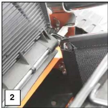
natural_image
Close-up of a mechanical assembly with metal components and a mesh component (no visible text or symbols)
natural_image
Electric lawn mower with a black cover and orange wheels, no visible text or symbolsMULCHING MOWING
6.25 Life the rear discharge flap and remove the grass collector (1).
6.26 Insert the mulching plug into the rear discharge chute until it clicks into place (2).
6.27 Lower the rear discharge flap (3).

natural_image
Close-up of a black and yellow utility lawn mower with visible wheels and mounting brackets (no text or symbols)
natural_image
Close-up of a hand adjusting a black plastic component next to a large orange and yellow lawn mower (no text or symbols visible)
natural_image
Close-up of a small manual lawn mower with orange wheels and black casing (no visible text or symbols)natural_image
Close-up of a hand adjusting a black plastic component on an orange lawn (no visible text or symbols)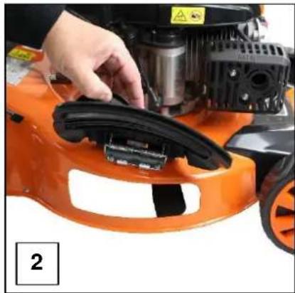
natural_image
Close-up of a hand adjusting an orange lawn mower with mechanical components (no visible text or symbols)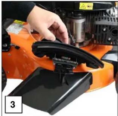
natural_image
Close-up of a hand operating an orange agricultural machine with a black handle and mechanical components (no visible text or symbols)6.31 Lower the side discharge flap so it rests on the top of the side discharge chute (1).
natural_image
Close-up of an orange lawn mower with visible mechanical components and a black plastic cover (no text or symbols)WARNING
ALWAYS stop the engine, unplug the spark plug HT lead and allow the engine to cool before carrying out any repairs, maintenance, refuelling or removal of blockages.
NEVER touch any rotating part of the lawn mower.
ALWAYS wear appropriate Personal Protective Equipment (PPE) when using or maintaining this machine.

HAND
PROTECTION
MUST BE WORN

EYE
PROTECTION
MUST BE WORN

PROTECTIVE CLOTHING MUST BE WORN

HEARING
PROTECTION
MUST BE WORN

FOOT
PROTECTION
MUST BE WORN

HEAD
PROTECTION
MUST BE WORN

RESPIRATOR
MUST BE WORN

FACE SHIELD
MUST BE WORN
ALWAYS fuel and defuel in a well ventilated area with the engine off and allowed to cool.
NEVER start or run the machine indoors or in an enclosed space. This machine produces carbon monoxide which can kill.

text_image
DANGER! BREATHING IN CARBON MONOXIDE FUMES CAN KILL YOU! To help protect against CO poisoning install a Carbon Monoxide detector. NEVER use Petrol/Diesel powered equipment inside, especially a home, garage, tent, camper-van, caravan, motorhome or boat. EVEN if doors, windows, vents and hatches are open. Only use OUTDOORS and as far away from doors, windows, vents and open hatches as possible to prevent inhaling fumes. READING MANUAL BEFORE USE WILL HELP AVOID OTHER MACHINE HAZARDS.NOTE
Before use you MUST check and if necessary, adjust the Operator Presence Control (OPC) cable.
If the cable is too loose, the lawn mower will not start.
There should be no more than 10mm free play in the OPC cable.
To check, start to pull the OPC lever towards the main handle.
The OPC cable should start to move within 10mm of pulling the handle.
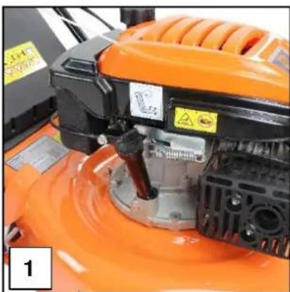
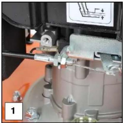
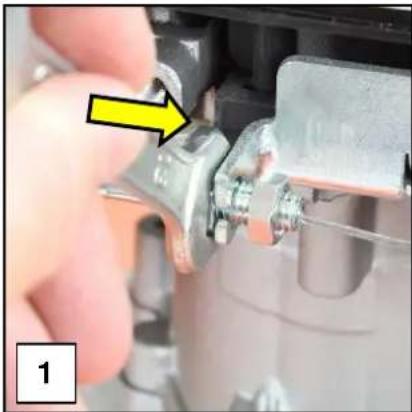
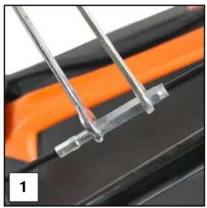
3.27 If adjustment is required, trace the OPC cable down from the handle to the engine of the lawn mower, until you reach the OPC cable adjuster (1).
3.28 Undo the lock nut (2) and wind it forwards (3).
natural_image
Close-up of a mechanical assembly with no visible text or symbols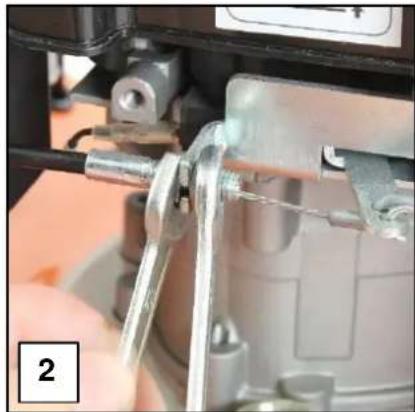
natural_image
Close-up of a mechanical assembly with metal components and a hand holding a tool (no visible text or symbols)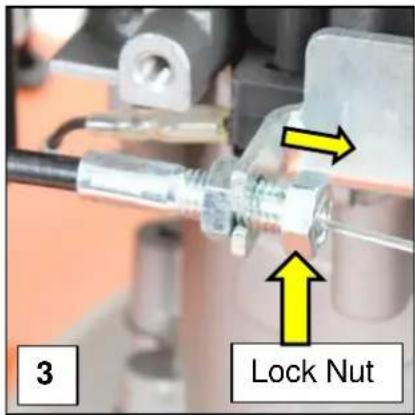
text_image
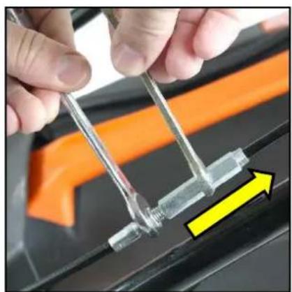
3 Lock Nut3.29 Wind the adjuster nut towards the lock nut.
As you adjust, keep checking the tension on the OPC cable until the desired tension is reached.
3.30 Tighten the lock nut back towards the adjuster nut (2) and then attempt to start the lawn mower.
3.31 If the lawn mower starts, tighten both nut securely.
If not, repeat the process until the lawn mower will start.
natural_image
Close-up of a hand adjusting a mechanical component with a yellow arrow pointing to a detail (no visible text or symbols)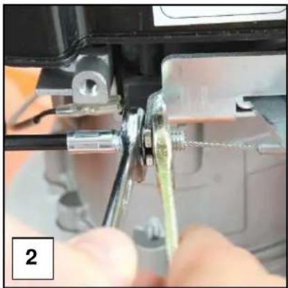
natural_image
Close-up of hands using a tool to adjust or install a mechanical component, no visible text or symbolsNOTE
There should be no more than 10mm free play in the drive cable for a self-propelled lawn mower, otherwise the self-propelled drive will fail to work correctly.
To check, start to pull the drive lever towards the main handle.
The drive cable should start to move within 10mm of pulling the handle.
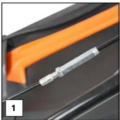
3.32 There should be no more that 10mm free play in the drive cable, when you check the cable for tension.
3.33 If adjustment is required, trace the drive cable down towards the gearbox of the lawn mower, until you reach to drive cable adjuster (1).
3.34 Undo the lock nut and wind away from the adjuster nut (2).
natural_image
Close-up of a black plastic connector with orange and black bands, no visible text or symbols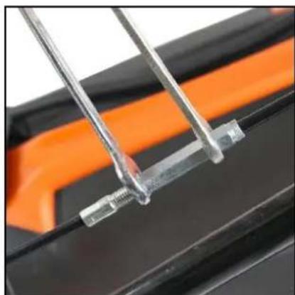
natural_image
Close-up of metallic tools and a small mechanical component on a black surface, with orange bands in the background (no visible text or symbols)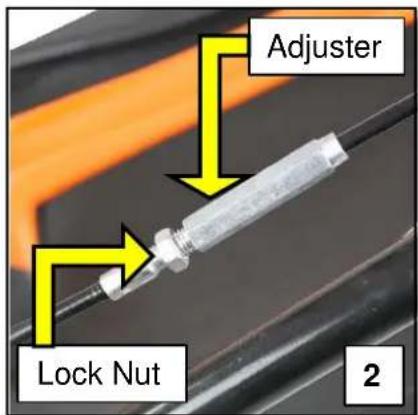
text_image
Adjuster Lock Nut 23.34 Wind the adjuster nut towards the main handlebar.
As you adjust, keep checking the tension on the drive cable until the desired tension is reached (1).
3.35 Tighten the lock nut finger tight, back towards the adjuster nut (2) and check for drive on the lawn mower.
Once drive is restored, tighten the lock nut securely.
natural_image
Close-up of hands holding a transparent tool with a yellow arrow pointing to a small component, against an orange and black background (no text or symbols visible)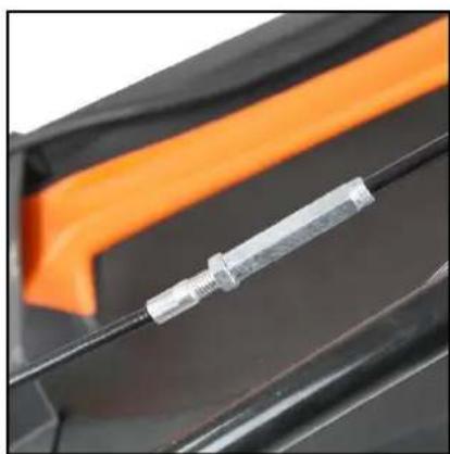
natural_image
Close-up of a metallic screwdriver inserted into a black plastic component with an orange stripe (no text or symbols visible)NOTE
Oil Type All Models: Semi Synthetic SAE15W40 Engine Oil
Oil Capacity P4100P: 400ml
Oil Capacity P4600SP & P5100SPE: 600ml
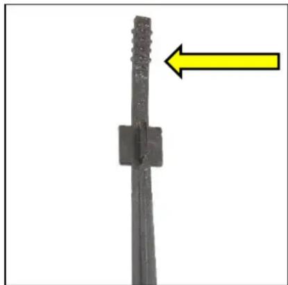
7.0 The oil must be checked before every use.
7.1 We recommend doing an oil service at least once a year, more frequently during periods of heavy use.
7.2 Disconnect the spark plug HT lead cap and with the engine oil warm, not hot, remove the dipstick.
7.3 Gently tilt the machine to allow the oil to drain from the dipstick port into a suitable container.
7.4 Refill slowly with approx. 600ml of fresh Semi-Synthetic SAE 15W40 engine oil to the upper level mark on the dipstick.
7.5 Stop occasionally to check the oil level.
natural_image
Close-up of a black metal rod with a yellow arrow pointing to its left side (no text or symbols)7.6 Do not overfill.
7.7 If you do overfill, gently tilt the machine and allow the excess oil to drain from the dipstick port, in to a suitable container.
7.8 Refit the dipstick securely.
NOTE
Recommended Spark Plug P4100P: NGK BPR6ES or equivalent
Recommended Spark Plug P4600SP & P5100SPE: NGK BP6ES or equivalent
Spark Plug Gap All Models: 0.7 \~ 0.8mm (0.28" \~ 0.32")
7.9 We recommend checking the spark plug after every 25 hours of use and replacing once a year.
7.10 Allow the engine to completely cool.
7.11 Remove the spark plug HT lead cap (1) to expose the spark plug (2).
7.12 Using a spark plug spanner (3), remove the spark plug (4).

natural_image
Close-up of a hand inserting a component into an orange industrial machine (no visible text or symbols)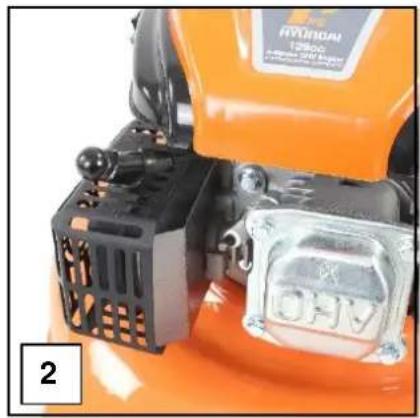
natural_image
Close-up of an orange and black robotic device with visible internal components (no readable text or symbols)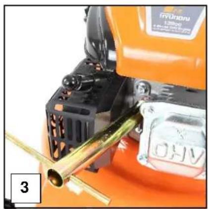
natural_image
Close-up of an orange industrial machine component with brass tubing and a yellow handle (no visible text or symbols)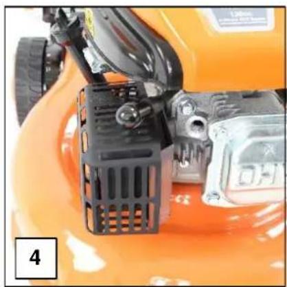
natural_image
Close-up of an orange motorcycle's front wheel and side-mounted air purifier (no visible text or symbols)7.13 Inspect and clean the spark plug electrode, making sure there is no damage to the insulator or electrode.
7.14 If there is any damage or wear to the spark plug, replace immediately.
7.15 Using a feeler gauge, check the spark plug gap.
The plug gap should be 0.70mm to 0.80mm, carefully adjust the plug gap by bending the side electrode.
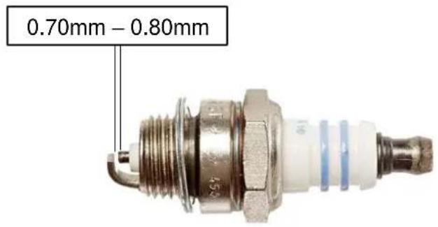
text_image
0.70mm - 0.80mm7.16 Refit the cleaned and adjusted spark plug by hand to avoid cross threading.
7.17 Once the spark plug seats, tighten with the spark plug spanner DO NOT over tighten.
7.18 Replace the spark plug HT lead cap.
AIR FILTER
CAUTION
Never operate the lawn mower without an air filter installed. It can cause damage to the engine which will not be covered by the warranty.
When using the lawn mower in very dusty areas, you must clean or replace the air filter more frequently.
7.19 We recommend checking the air after every 25 hours of use and replacing once a year.
7.20 Allow the engine to completely cool and disconnect the spark plug HT lead cap.
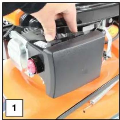
7.21 Push down the latch tabs on the side of the air filter box (1) to reveal the air filter (2).
7.22 Remove the air filter (3) and ensure no dirt or debris can enter the carburetor chamber.
natural_image
Close-up of a hand adjusting a black electronic device on an orange vehicle (no visible text or symbols)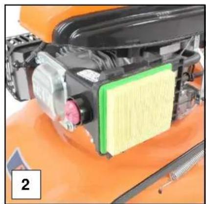
natural_image
Close-up of an orange industrial machine component with visible internal structure and yellow foam layer (no text or symbols)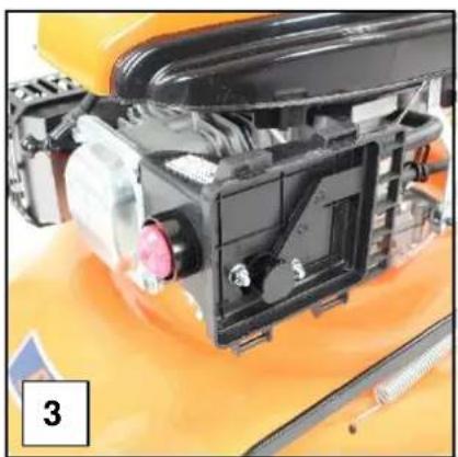
natural_image
Close-up of a yellow industrial machine head assembly with visible internal components and mounting brackets (no text or symbols)7.22 If a paper air filter is fitted, inspect and replace if necessary. Otherwise gently blow compressed air, not exceeding 30psi, through the filter from the reverse side to remove the majority of dirt and debris and reinstall.
7.33 If a foam filter is installed, inspect and replace if necessary.
Otherwise, was the air filter in a warm soap solution, rinse and allow to dry.
7.34 Once dry, soak the foam filter in fresh engine oil and allow the excess to drain off.
7.35 Reinstall the air filter and close the air filter cover.
LAWN OWER BLADE
CAUTION
ALWAYS handle the lawn mower blade wearing thick gloves suitable for purpose.
Lawn mower blades can be sharp and cause personal injury if handled incorrectly.
7.36 We recommend inspecting the blade for wear or damage every 25 hours of work.
7.37 To inspect or remove the blade it is advisable to drain all the fluids from the mower and disconnect the spark plug HT lead cap before inspecting.
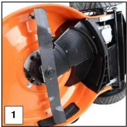
7.38 Turn the lawn mower on to its side (1) making sure the side the air filter is installed on, is facing up.
7.39 Using suitable cloves, firmly hold the blade and undo the centre bolt in an anti-clockwise direction (2).
NOTE: this may be stiff as the bolt needs to be installed tightly.
7.40 Remove the blade (3).
natural_image
Close-up of an orange saw blade assembly with black blades and a central fan (no visible text or symbols)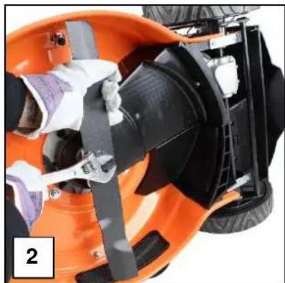
natural_image
Close-up of an orange and black motorcycle seat assembly (no visible text or symbols)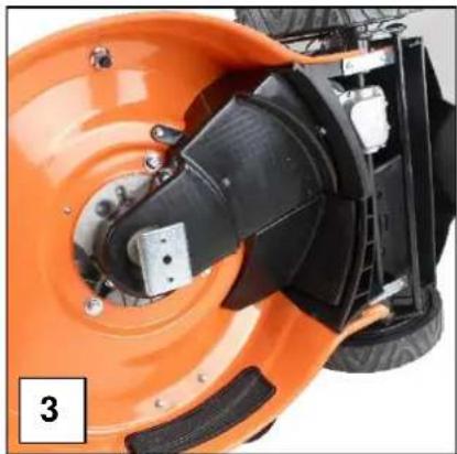
natural_image
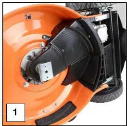
Close-up of an orange industrial saw blade assembly with black components and mounting hardware (no visible text or symbols)7.41 With the blade removed, inspect for straightness, damage and wear.
Replace the blade if it shows signs of any of these, otherwise have the blade sharpened and balanced.
7.42 Reinstall the blade securely by reversing the procedure above.
DRIVE BELT
CAUTION
ALWAYS handle the lawn mower blade wearing thick gloves suitable for purpose.
Lawn mower blades can be sharp and cause personal injury if handled incorrectly.
7.43 We recommend inspecting the drive belt as part of an annual inspection. More frequently during periods of heavy use.
7.44 If drive has been lost, check the cable adjustment first as set out in sections 3.32 to 3.35 before inspecting the belt.
7.45
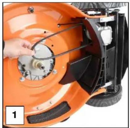
7.46 Remove the lawn mower blade as set out in sections 7.37 to 7.42.
7.47 Remove the drive coupling and spacer (1 & 2).
Be careful not to lose the keyway attached to the drive shaft (3).
natural_image
Close-up of an orange industrial tire with black mechanical components and a small inset showing a device (no visible text or symbols)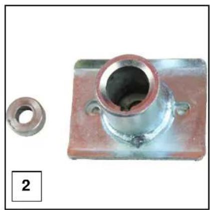
natural_image
Two metallic mechanical components: a circular hole and a square plate with mounting holes (no text or symbols visible)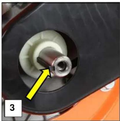
natural_image
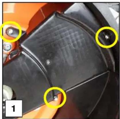
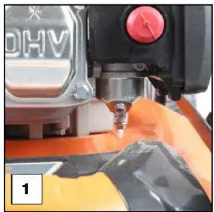
Close-up of a mechanical component with a yellow arrow pointing to a cylindrical part, no visible text or symbols.7.48 Remove the plastic drive belt guard by undoing the 2 bolts and screw holding it in place (1) to expose the drive belt (2).
7.49 Inspect the belt for wear or damage and check tension (3).
There should be no more than 10mm free play when gently checking tension.
natural_image
Close-up of a black mechanical component with two yellow circles highlighting features, no visible text or symbols.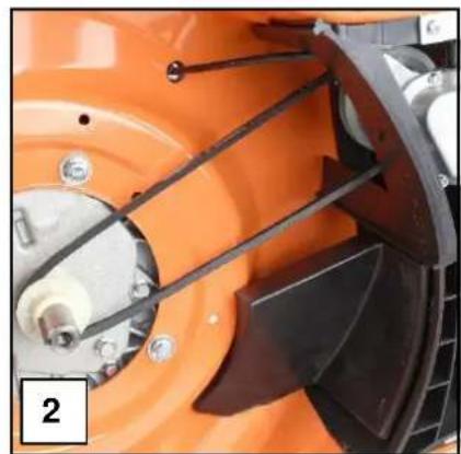
natural_image
Close-up of an orange industrial fan or blade assembly with black blades and mounting holes (no visible text or symbols)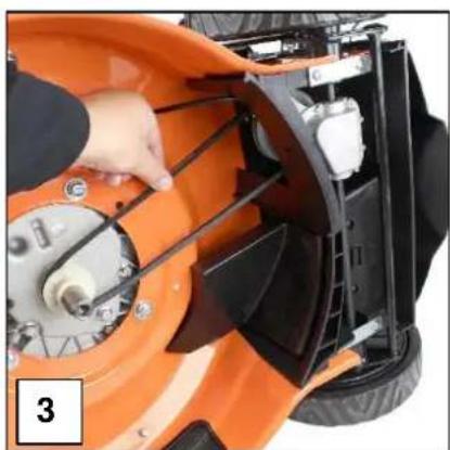
natural_image
Close-up of a hand operating the blade of an orange lawn mower, showing mechanical components and no visible text or symbols.7.50 If the belt is damaged or worn, replace immediately.
7.51 Loosen the tension on the drive belt by undoing the lock nut on the drive cable (1 & 2).
7.52 Wind the lock nut and the adjuster nut all the way to the bottom to allow enough free play to be able to remove the drive belt (3).
natural_image
Close-up of a mechanical component with metal rods and a small transparent clip, against an orange and black background (no text or symbols visible)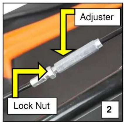
text_image
Adjuster Lock Nut 2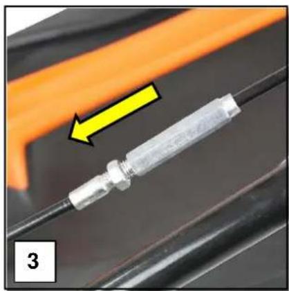
natural_image
Close-up of a metallic cylindrical component mounted on a black metal rod, with an orange arrow pointing to it (no text or symbols visible)7.53 Unhook the belt from the main drive pulley (1).
7.54 Unhook the belt from the rear pulley (2).
7.55 The belt should now be free to remove completely (3).
natural_image
Close-up of an orange lawn mower with a hand adjusting the blade (no visible text or symbols)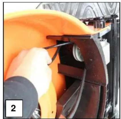
natural_image
Close-up of a person using a tool to adjust or install a yellow industrial component, no visible text or symbols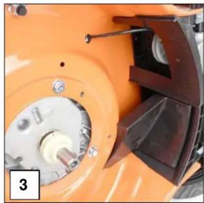
natural_image
Close-up of an orange agricultural machine component with visible gears and a blade (no text or symbols)7.56 To reinstall, reverse the procedure above.
WARNING
ALL FUELS ARE HIGHL FLAMMABLE
ALWAYS fuel and defuel in a well ventilated area outside of buildings and away from any possible sources of ignition.
7.57 To drain fuel from the float bowl of the carburetor, drain all the fuel from the fuel tank.
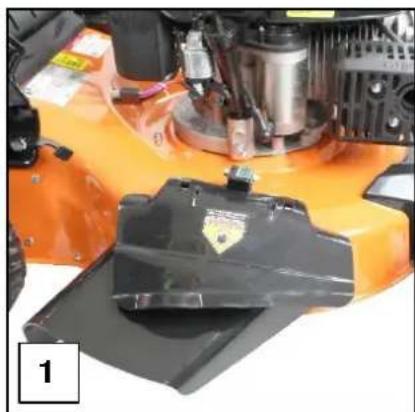
7.58 Locate the carburetor float bowl at the front of the lawn mower (1).
7.59 Place a suitable container underneath the float bowl and unscrew the drain screw located on the angled side of the float bowl (2).
7.60 Take care not to lose the washer on the drain screw.
7.61 Allow all the fuel to drain before reinstalling the drain plug screw.
natural_image
Close-up of a robotic arm in action, showing a hand operating a yellow tool with orange paint (no visible text or symbols)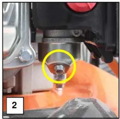
natural_image
Close-up of a precision machine tool with a yellow circle highlighting a bolt (no visible text or symbols)CLEANING
NOTE
DO NOT use a pressure washer or hose pipe to clean your lawn mower (unless fitted with hose pipe attachment).
Water could damage internal and external components of the lawn mower and engine and cause catastrophic failure that will not be covered by the warranty.
It is recommended to clean your lawn mower after every use to help prolong the life of the lawn mower and ensure it works efficiently.
7.62 Allow the lawn mower to cool completely and remove the spark plug HT lead cap.
7.63 Remove any clippings or debris from the top of the lawn mower deck.
7.64 Check the cooling fins on the engine are free from dirt and debris. Use a soft brush to clean if required.
7.65 Lightly grease any moving cables or parts using a silicone based spray grease.
7.66 Drain all the fuel and oil from the lawn mower.
7.67 If your lawn mower is fitted with a deck mounted hose port, connect a hose pipe to the port and rinse the underside of the lawn mower deck.
7.68 Remove the grass bag and place the lawn mower on its side ensuring the air filter is facing up.
7.69 Wearing suitable gloves and using a damp cloth, wipe away any grass clipping from the underside of the lawn mower deck and the lawn mower blade.
7.70 For more stubborn or dried on clippings use a hand trowel or similar.
7.71 Using a damp (not wet) cloth, wipe the underside of the lawn mower deck and blade.
7.72 Wipe over with a dry cloth.
9. STORAGE & WINTERISATION
NOTE
If storing the lawn mower for a period of 30 days or more, you must follow proper storage and winterisation guidelines to avoid any possible issues with your lawn mower.
Incorrect storage can lead to possible fueling or engine issues that will not be covered by the warranty.
8.0 Drain all the fuel from the fuel tank and then run the lawn mower until it has completely run out of fuel to clear the remaining fuel from the fuel lines and carburetor.
8.1 Drain the oil from the engine as set out in section 7.1 to 7.3.
8.2 With the lawn mower drained of all fluids, follow the cleaning instructions as set out in section 7.62 to 7.72.
8.3 Follow the maintenance section and check, service or replace serviceable items if required.
8.4 Using a silicone spray grease, lightly coat the lawn mower blade to prevent possible rusting during storage.
8.5 Using a silicone spray grease, lightly grease all moving parts on the lawn mower.
8.6 Refill the engine with approx. 600ml of Semi Synthetic SAE15W40 engine oil.
8.7 Remove the spark plug and pour 1 teaspoon of fresh engine oil down the cylinder bore. Cover the spark plug hole with a lint free clean cloth, ensuring no dirt or debris falls into the cylinder chamber and gently pull the recoil starter handle to coat the cylinder bore with the fresh oil.
8.8 Refit the spark plug.
8.9 Store the lawn mower in a cool, dry place away from sources of ignition and varying changes in temperature.
8.10 Do not stack anything on top of the lawn mower.
CAUTION
Where necessary, all corrective actions should be carried out by suitably qualified persons.
| Problem | Possible Cause | Possible Corrective Action |
| Engine does not start | OPC cable not adjusted correctly | Adjust OPC cable |
| Fuel tank is empty | Fill fuel tank | |
| Stale fuel | Drain carburetor float bowl | |
| Air filter element is dirty | Clean or replace air filter | |
| Spark plug is loose | Tighten spark plug | |
| Spark plug cap loose or disconnected | Correctly fit the spark plug cap | |
| Spark plug faulty | Spark plug gap is incorrect | Set plug gap to 0.7 – 0.8mm or Replace spark plug |
| Carburetor is flooded with fuel | Remove the air filter and pull starter rope until carburetor clears | |
| Faulty ignition module | Contact the service dealer | |
| Engine difficult to start or loses power | Dirt, water or stale fuel in tank | Drain fuel and clean tank Fill with clean, fresh fuel |
| Vent hole in fuel tank is clogged | Clean or replace fuel tank cap | |
| Air filter element is dirty | Clean or replace air filter element | |
| Engine operates erratically | Spark plug is defective | Fit new, correctly gapped spark plug |
| Spark plug gap is incorrect | Set plug to 0.7 – 0.8mm | |
| Air filter element is dirty | Clean or replace air filter element | |
| Engine idles poorly | Air filter element is dirty | Clean or replace air filter element |
| Air slots in engine are blocked | Remove debris from slots | |
| Cooling fins and air passages under engine housing are blocked | Remove debris from cooling fins and passages | |
| Engine skips at high speed | Spark plug electrode gap is incorrect | Set plug gap to 0.7 – 0.8mm |
| Engine Overheating | Cooling airflow is restricted | Remove any debris from slots in shroud, blower housing, air passages |
| Incorrect spark plug | Fit new spark plug | |
| Mower vibrates abnormally DO NOT use the machine until vibration issue has been fixed | Cutting assembly is loose | Tighten blade |
| Blade/cutting assembly is unbalanced | Take to a service dealer |
- SPECIFICATION
| P4100P | P4600SP | P5100SPE | |
| Engine Type | Hyundai OHV 4-Stroke | ||
| Engine Size - cc | 79 | 139 | 173 |
| Fuel Tank Capacity - l | 0.8 | 1.0 | 1.0 |
| Fuel Type | Unleaded Petrol | ||
| Oil Capacity - ml | 600 | 600 | 600 |
| Oil Type | Semi Synthetic SAE15W40 | ||
| Rated Speed - rpm | 2800 | ||
| Rated Power - kW | 1.8 | 3.6 | 4.2 |
| Drive Type | Push | Self-Propelled | Self-Propelled |
| Start Method | Recoil | Recoil | Recoil/Electric |
| Height Adjustment | 3 | 6 | 6 |
| Cutting Height - mm | 25 - 65 | 25 - 75 | |
| Cutting Width - mm | 400 | 460 | 510 |
| Cut and Collect | Yes | Yes | Yes |
| Cut and Drop | No | No | Yes |
| Mulching | No | No | Yes |
| Catcher Type | Polyester | Polyester | Polyester/Plastic |
| Catcher Volume - l | 40 | 60 | 60 |
| Deck Material | Treated Steel | ||
| Wheel Size Front - mm | 150 | 180 | 200 |
| Wheel Size Rear - mm | 150 | 250 | 280 |
| Handle Type | Soft Grip | ||
| Noise Level - dB | 96 | 96 | 96 |
| Net Weight - Kg | 21.5 | 33 | 37 |
| Product Dimensions - mm | 685 x 530 x 440 | 770 x 565 x 440 | 900 x 580 x 530 |
12. RECYCLING & PRODUCT DISPOSAL
9.0 We do not offer a takeback scheme for the recovery of Waste Electrical Electronic Equipment (WEEE) & Batteries.
Instead the responsibility to dispose of WEEE and or Batteries is passed onto you by us.
So when it becomes necessary to dispose of your machine you must take it to your local Civic Amenity Site.
For further information please contact your local Authority for disposal advice.
9.1 You MUST make sure that all unused oil and fuel is disposed of correctly either beforehand or at your local Civic Amenity Site.
Under NO circumstances must any fuel or oil be put down any drains.
9.2 Certain products contain WEEE waste which should not be disposed of in your domestic waste.
9.3 You MUST recycle WEEE in accordance with your local authority or recycling centre.
9.4 Certain products contain batteries which should not be disposed of in your domestic waste.
9.5 You MUST recycle batteries in accordance with your local authority or recycling centre.
9.6 Unwanted packaging and materials should be stored and taken to a recycling centre so it can be disposed of in a manner which is compatible with the environment.
9.7 The following symbol means that you should 'Reduce – Reuse – Recycle'.

natural_image
Simple line drawing of a trash bin with two crossed lines indicating no waste or restriction (no text or symbols)
9.8 We are a Member of the VALPAK National Compliance Scheme and our registration number is RM08660
9.9 For further information about disposal please contact your Local Authority.
9.10 You can also get more advice and guidance about recycling at the following website http://www.recycle-more.co.uk
9.11 Should you pass this product on to another user either sold or loaned, you MUST pass on this user manual.
This will make sure that all other users can use and maintain this machine safely.
13. DECLARATION OF CONFORMITY
Genpower Ltd confirms that these Hyundai products conform to the following CE Directives.
2006/42/EC Machinery Directive
2004/108/EC EMC Directive
2000/14/EC, Amended by 2005/88/EC Noise Emissions Directive
97/68/EC_2010/26/EC NRMM Emissions Directive
EC DECLARATION OF CONFORMITY
The undersigned. As authorised by: Genpower Ltd
Declares that the following equipment manufactured under licence
Conforms to the Directive:-
2000/14/EC (as amended)
Of the European Parliament and of the council on the approximation of the laws of the Member States relating to the noise emission in the environment by equipment for the use outdoors.
Equipment Category: Garden Machinery
Product Name/Model: P4100P
P4600SP
P5100SPE
Type/Serial No: Petrol Lawn Mower
Net installed power: P4100P 1.6kW
P4600SP 3.6kW
P5100SPE 4.2kW
The technical documentation is kept by: Roland Llewellin, Genpower Ltd
Isaac Way, Pembroke Dock,
Pembrokeshire, SA72 4RW.
The conformity assessment procedure followed was in accordance with annex V of the Directive.
Notified Body: TÜV Rheinland Luxemburg GmbH
2a Kalchesbruk
1852 Luxembourg.
Certification n° OR/027431/001
Measured Sound Power Level: P4100P 94dB
P4600SP 96dB
P5100SPE 96dB
Guaranteed Sound Power Level: P4100P 96dB
P4600SP 96dB
P5100SPE 96dB
A copy of this certificate has been submitted to the European Commission and the EU Member
State United Kingdom.
Place of Declaration: Pembroke Dock, SA73 4RW
Date: 07/03/2018
Signed by: Roland Llewellin
RJLevelm
Position in Company: Managing Director
Name and address of manufacturer or Authorised representative:
Genpower Ltd
Isaac Way, Pembroke Dock,
Pembrokeshire, SA72 4RW
14. CONTACT DETAILS
10.0 POSTAL ADDRESS Genpower Ltd, Isaac Way, London Road, Pembroke Dock, Pembrokeshire. SA72 4RW. United Kingdom
10.1 TELEPHONE +44 (0) 1646 687 880
10.2 FAX +44 (0) 1646 686 198
10.3 AFTER SALES aftersales@genpower.co.uk
10.4 WEB ADDRESS www.p1pe.co.uk
15. WARRANTY
11.0 To register your machine for the manufacturer's warranty, please visit https://www.p1pe.co.uk/warranty
16. MANUAL UPDATES
12.0 Our manuals are constantly being reviewed and updated.
However if you find an error, omission or something you find unclear, please contact your dealer for assistance.
12.1 Our latest manuals are also placed online.
12.2 We reserve the right to make any modifications without prior notice whenever necessary.

text_image
P1PE – P Isaac W Pembro SA72-4EPOSITION ONE POWER EQUIPMENT
P1PE – Position One Power Equipment Isaac Way, Pembroke Dock, Pembrokeshire.
SA72 4RW