
GSC 18ITC3-WTA - Air Conditioning Godrej - Free user manual and instructions
Find the device manual for free GSC 18ITC3-WTA Godrej in PDF.


| Brand | Godrej |
| Model | GSC 18ITC3-WTA |
| Product Type | Split Air Conditioner |
| Cooling Capacity | 5.0 kW (approx. 1.5 tons) |
| Power Supply | 230 V, 50 Hz, Single Phase |
| Indoor Unit Dimensions (W x H x D) | 790 x 268 x 198 mm |
| Outdoor Unit Dimensions (W x H x D) | 740 x 548 x 265 mm |
| Indoor Unit Weight | 9.5 kg |
| Outdoor Unit Weight | 27.0 kg |
| Refrigerant Type | R32 |
| Energy Efficiency Ratio (EER) | 3.5 (approx.) |
| Operating Modes | Cool, Dry, Fan, Auto |
| Fan Speeds | High, Medium, Low, Auto |
| Airflow (Indoor) | 580 m³/h |
| Remote Control | Included |
| Timer Function | On/Off Timer (0.5-24 hrs) |
| Sleep Mode | Available |
| Filter Type | Washable Dust Filter |
| Maintenance | Clean filters every 2 weeks |
| Safety Features | Auto restart, voltage protection, anti-corrosion coating |
| Installation | Professional installation recommended |
| Warranty | 1 year on product, 5 years on compressor |
Frequently Asked Questions - GSC 18ITC3-WTA Godrej
User questions about GSC 18ITC3-WTA Godrej
0 question about this device. Answer the ones you know or ask your own.
Ask a new question about this device
Download the instructions for your Air Conditioning in PDF format for free! Find your manual GSC 18ITC3-WTA - Godrej and take your electronic device back in hand. On this page are published all the documents necessary for the use of your device. GSC 18ITC3-WTA by Godrej.
USER MANUAL GSC 18ITC3-WTA Godrej
On behalf of Godrej Appliances, we welcome you to the Godrej family, and thank you for giving us an opportunity to serve you.
Godrej Appliances is a leading brand not just in technology and performance but also for its excellent customer service, we have more than 660 service centers across India, so that we can be close to our customers and serve them better.
In order to get the maximum out of your superior Air Conditioner, we urge you to go through this detailed user manual, if you need any assistance at any time, do not hesitate to call us on 1800 209 5511 or write to us at smartcare@godrej.com
We again thank you for giving us the privilege to serve you, and look forward to a long and delightful association.
Warm Regards, Team Godrej
| PERFORMANCE PARAMETERS | |||||||||
| MODEL NAME | GIC 18ATC3-WSA | GIC 18WTC3-WSA | GIC 12ATC3-WSA | GIC 12WTC3-WSA | GIC 12ATC5-WSA | GIC 12WTC5-WSA | GIC 18ATC5-WSA | GIC 18WTC5-WSA | |
| OPERATING MODE | Cooling | Cooling | Cooling | Cooling | Cooling | Cooling | Cooling | Cooling | |
| RATED VOLTAGE | 230 V | 230 V | 230 V | 230 V | 230 V | 230 V | 230 V | 230 V | |
| RATED FREQUENCY/PHASE | 50 Hz/10 | 50 Hz/10 | 50 Hz/10 | 50 Hz/10 | 50 Hz/10 | 50 Hz/10 | 50 Hz/10 | 50 Hz/10 | |
| COOLING CAPACITY (W) | 5250W | 5250 W | 3500 W | 3500 W | 3500W | 3500W | 5250W | 5250W | |
| RATED POWER INPUT (W) | 1700W | 1700W | 1040W | 1040W | 890W | 890W | 1350W | 1350W | |
| AIR FLOW VOLUME | 960 CMH | 960 CMH | 750 CMH | 750 CMH | 750 CMH | 750 CMH | 1045 CMH | 1045 CMH | |
| RATED INPUT CURRENT | 7.80A | 7.80A | 4.74A | 4.74A | 4.10A | 4.10A | 6.20A | 6.20A | |
| REFRIGERANT | R32 | R32 | R32 | R32 | R32 | R32 | R32 | R32 | |
| REFRIGERANT CHARGE | 0.80 kg | 0.80 kg | 0.53 kg | 0.53 kg | 0.80 kg | 0.80 kg | 0.90 kg | 0.90 kg | |
| COMP LRA | 18.0A | 18.0A | 18.0A | 18.0A | 18.0A | 18.0A | 18.0A | 18.0A | |
| WEIGHT | IDU | 12.5 kg | 12.5 kg | 9.30 kg | 9.30 kg | 9.30 kg | 9.30 kg | 12.50 kg | 12.50 kg |
| ODU | 31.5 kg | 31.5 kg | 27.0 kg | 27.0 kg | 29.0 kg | 29.0 kg | 34.0 kg | 34.0 kg | |
| MODEL NAME | GSC 18WTC3-WSA | GSC 18ATC3-WSA | GSC 12RTC3-WRA | GIC 12RTC3-WRA | GIC 12RTC5-WRA | GIC 18RTC5-WRA | GSC 18RTC3-WRA | GSC 12ATC3-WSA | |
| OPERATING MODE | Cooling | Cooling | Cooling | Cooling | Cooling | Cooling | Cooling | Cooling | |
| RATED VOLTAGE | 230 V | 230 V | 230 V | 230 V | 230 V | 230 V | 230 V | 230 V | |
| RATED FREQUENCY/PHASE | 50 Hz/10 | 50 Hz/10 | 50 Hz/10 | 50 Hz/10 | 50 Hz/10 | 50 Hz/10 | 50 Hz/10 | 50 Hz/10 | |
| COOLING CAPACITY (W) | 5250W | 5250W | 3400W | 3400W | 3400W | 5100W | 5100W | 3500W | |
| RATED POWER INPUT (W) | 1490W | 1490W | 955W | 985W | 870W | 1325W | 1450W | 984W | |
| AIR FLOW VOLUME | 1025 CMH | 1025 CMH | 750 CMH | 750 CMH | 750 CMH | 1045 CMH | 1025 CMH | 750 CMH | |
| RATED INPUT CURRENT | 6.90A | 6.90A | 4.37A | 4.51A | 3.98A | 6.10A | 6.64A | 4.50A | |
| REFRIGERANT | R32 | R32 | R32 | R32 | R32 | R32 | R32 | R32 | |
| REFRIGERANT CHARGE | 0.95 kg | 0.95 kg | 0.70 kg | 0.53 kg | 0.80 kg | 0.90 kg | 0.95 kg | 0.70 kg | |
| COMP LRA | 37.0A | 37.0A | 25.0A | 18.0A | 18.0A | 18.0A | 37.0A | 25.0A | |
| WEIGHT | IDU | 12.50 kg | 12.50 kg | 9.30 kg | 9.30 kg | 9.30 kg | 12.50 kg | 12.50 kg | 9.30 kg |
| ODU | 40.0 kg | 40.0 kg | 29.5 kg | 27.0 kg | 29.0 kg | 34.0 kg | 40.0 kg | 29.50 kg | |
| PERFORMANCE PARAMETERS | ||||||||||
| MODEL NAME | GSC 12WTC3-WSA | GSC 18KTC3-WSA | GSC 18LTC3-WSA | GIC 18 RINV 3 DWQR | GIC 24LTC3-WSA | GSH 18LTC2-WSA | GIC 24ITC3-WTA | GSC 18ITC3-WTA | ||
| OPERATING MODE | Cooling | Cooling | Cooling | Cooling | Cooling | Cooling | Heating | Cooling | Cooling | |
| RATED VOLTAGE | 230 V | 230 V | 230 V | 230 V | 230 V | 230 V | 230 V | 230 V | ||
| RATED FREQUENCY/PHASE | 50 Hz/1∅ | 50 Hz/1 ∅ | 50 Hz/1 ∅ | 50 Hz/1∅ | 50 Hz/1∅ | 50 Hz/1∅ | 50 Hz/1∅ | 50 Hz/1∅ | ||
| COOLING CAPACITY/HEATING CAPACITY (W) | 3500W | 5100W | 5250W | 5100 W | 6250 W | 5000 W | 5000 W | 6250W | 5200W | |
| RATED POWER INPUT (W) | 984W | 1450W | 1490W | 1670 W | 2050 W | 1510 W | 1510 W | 2050W | 1485W | |
| AIR FLOW VOLUME | 750 CMH | 1080 CMH | 1080 CMH | 960 CMH | 1180 CMH | 1180 CMH | 1180 CMH | 1080 CMH | ||
| RATED INPUT CURRENT | 4.50A | 6.40A | 6.60A | 7.50A | 9.40A | 7.00A | 7.00A | 9.40A | 6.80A | |
| REFRIGERANT | R32 | R32 | R32 | R32 | R32 | R32 | R32 | R32 | ||
| REFRIGERANT CHARGE | 0.70 kg | 0.88 kg | 0.88 kg | 0.80 kg | 0.87 kg | 1.23 kg | 0.87 kg | 0.88 kg | ||
| COMP LRA | 25.0A | 37.0A | 37.0A | 18.0A | 18.0A | 37.0A | 18.0A | 35.0A | ||
| WEIGHT | IDU | 9.30 kg | 11.50 kg | 11.50 kg | 12.5 kg | 11.0 kg | 11.0 kg | 11.0 kg | 11.5 kg | |
| ODU | 29.50 kg | 38.0 kg | 38.0 kg | 31.5 kg | 34.0 kg | 41.6 kg | 34.0 kg | 35.0 kg | ||
CONTENTS
SAFETY 1
NAME OF PARTS 8
INDOORDISPLAY 9
Protection of Environment:
Protection of environment" is one of the core values of Godrej and we seek your co-operation to make sure that the product, packaging and plastic material is not disposed as unsorted municipal waste.
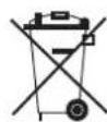
This symbol is known as the "Crossed-out Wheelie Bin Symbol". It means that the product should not be disposed of with your general house-hold waste.
It should be disposed of only through the company's collection points with special treatment so as to prevent any damage to the environment. Please call: 1800 209 5511 for applicable buy back arrangement or visit: www.godreappliances.com/green-think for details about Godrej Appliances authorised collection points.
In line with the company's policy of continual product improvement, the aesthetic and dimensional characteristics, technical data and accessories of this appliance may be changed without notice.

Appliance filled with flammable gas R32.

Before use the appliance, read the owner's manual first.

Before install the appliance, read the installation manual first.

Before repair the appliance, read the service manual first.
The Refrigerant
- To realize the function of the air conditioner unit, a special refrigerant circulates in the system. The used refrigerant is the fluoride R32, which is specially cleaned. The refrigerant is flammable and inodorous. Furthermore, it can leads to explosion under certain conditions. But the flammability of the refrigerant is very low. It can be ignited only by fire.
- Compared to common refrigerants, R32 is a nonpolluting refrigerant with no harm to the ozonosphere. The influence upon the greenhouse effect is also lower. R32 has got very good thermodynamic features which lead to a really high energy efficiency. The units therefore need a less filling.
WARNING
Do not use means to accelerate the defrosting process or to clean, other than those recommended by the manufacture. Should repair be necessary, contact your nearest authorized Service Centre. Any repairs carried out by unqualified personnel may be dangerous. The appliance shall be stored in a room without continuously operating ignition sources. (for example: open flames, an operating gas appliance or an operating electric heater.) Do not pierce or burn.
Appliance filled with flammable gas R32. For repairs, strictly follow manufacturer's instructions only. Be aware that refrigerants not contain odour. Read specialist's manual.


PRECAUTIONS

WARNING
Operation and Maintenance
•This appliance can be used by children aged from 8 years and above and persons with reduced physical, sensory or mental capabilities or lack of experience and knowledge if they have been given supervision or instruction concerning use of the appliance in a safe way and understand the hazards involved.
•Children shall not play with the appliance.
- Cleaning and user maintenance shall not be made by children without supervision.
- Do not connect air conditioner to multi-purpose socket. Otherwise, it may cause fire hazard.
- Do disconnect power supply when cleaning air conditioner. Otherwise, it may cause electric shock.
- If the supply cord is damaged, it must be replaced by the manufacturer, its service agent or similarly qualified persons in order to avoid a hazard.
- Do not wash the air conditioner with water to avoid electric shock.
- Do not spray water on indoor unit. It may cause electric shock or malfunction.
•After removing the filter, do not touch fins to avoid injury.
- Do not use fire or hair dryer to dry the filter to avoid deformation or fire hazard.
PRECAUTIONS

WARNING
- Maintenance must be performed by qualified professionals. Otherwise, it may cause personal injury or damage.
- Do not repair air conditioner by yourself. It may cause electric shock or damage. Please contact dealer when you need to repair air conditioner.
- Do not extend fingers or objects into air inlet or air outlet. It may cause personal injury or damage.
- Do not block air outlet or air inlet. It may cause malfunction.
- Do not spill water on the remote controller, otherwise the remote controller may be broken.
- When below phenomenon occurs, please turn off air conditioner and disconnect power immediately, and then contact the dealer or qualified professionals for service.
• Power cord is overheating or damaged. - There's abnormal sound during operation.
- Circuit break trips off frequently.
• Air conditioner gives off burning smell. - Indoor units is leaking.
- If the air conditioner operates under abnormal conditions, it may cause malfunction, electric shock or fire hazard.
- When turning on or turning off the unit by emergency operation switch, please press this switch with an insulating object other than metal.
- Do not step on top panel of outdoor unit, or put heavy objects. It may cause damage or personal injury.
PRECAUTIONS

WARNING
Attachment
• Installation must be performed by qualified professionals. Otherwise, it may cause personal injury or damage.
- Must follow the electric safety regulations when installing the unit.
- According to the local safety regulations, use qualified power supply circuit and circuit break.
- Do install the circuit break. If not, it may cause malfunction.
- An all-pole disconnection switch having a contact separation of at least 3mm in all poles should be connected in fixed wiring.
- Including a circuit break with suitable capacity, please note the following table. Air switch should be included magnet buckle and heating buckle function, it can protect the circuit-short and overload.
• Air Conditioner should be properly grounded. Incorrect grounding may cause electric shock.
- Don't use unqualified power cord.
• Make sure the power supply matches with the requirement of air conditioner. Unstable power supply or incorrect wiring or malfunction. Please install proper power supply cables before using the air conditioner.
• Properly connect the live wire, neutral wire and grounding wire of power socket.
- Be sure to cut off the power supply before proceeding any work related to electricity and safety.
PRECAUTIONS

WARNING
- Do not put through the power before finishing installation.
- If the supply cord is damaged, it must be replaced by the manufacturer, its service agent or similarly qualified persons in order to avoid a hazard.
- The temperature of refrigerant circuit will be high, please keep the interconnection cable away from the copper tube.
- The appliance shall be installed in accordance with national wiring regulations.
• Installation must be performed in accordance with the requirement of NEC and CEC by authorized personnel only. - The air conditioner is the first class electric appliance. It must be properly grounding with specialized grounding device by a professional. Please make sure it is always grounded effectively, otherwise it may cause electric shock.
- The yellow-green wire in air conditioner is grounding wire, which can't be used for other purposes.
- The grounding resistance should comply with national electric safety regulations.
- The appliance must be positioned so that the plug is accessible.
- All wires of indoor unit and outdoor unit should be connected by a professional.
- If the length of power connection wire is insufficient, please contact the supplier for a new one. Avoid extending the wire by yourself.
PRECAUTIONS

WARNING
• For the air conditioner with plug, the plug should be reachable after finishing installation.
- For the air conditioner without plug, a circuit break must be installed in the line.
- If you need to relocate the air conditioner to another place, only the qualified person can perform the work. Otherwise, it may cause personal injury or damage.
- Select a location which is out of reach for children and far away from animals or plants. If it is unavoidable, please add the fence for safety purpose.
• The indoor unit should be installed close to the wall.
- Please notice that the unit is filled with flammable gas R32. Inappropriate treatment of the unit involves the risk of severe damages of people and material. Details to this refrigerant are found in chapter "refrigerant".
- Check whether the maintenance area or the room area meet the requirement of the nameplate.
- It's only allowed to be operated in the rooms that meet the requirement of the nameplate.
- Check whether the maintenance area is well-ventilated.
- The continuous ventilation status should be kept during the operation process.
- Check whether there is fire source or potential fire source in the maintenance area.
- The naked flame is prohibited in the maintenance area; and the "no smoking" warning board should be hanged.
- Check whether the appliance mark is in good condition.
- Replace the vague or damaged warning mark.
- Please use the flammable gas detector to check before unload and open the container.
• No fire source and smoking.
• According to the local rules and laws.
PRECAUTIONS

WARNING
- The air conditioner is not allowed to use in a room that has running fire (such as fire source, working coal gas ware, operating heater).
- It is not allowed to drill hole or burn the connection pipe.
- The air conditioner must be installed in a room that is larger than the minimum room area. The minimum room area is shown on the nameplate or following table a.
- Leak test is a must after installation.
- Instructions for installation and use of this product are provided by the manufacturer.
NAME OF THE PARTS
INDOOR UNIT
| No. | Description |
| 1 | Front panel |
| 2 | Air filter |
| 3 | Optional filter (if installed) |
| 4 | LED Display |
| 5 | Signal receiver |
| 6 | Terminal block cover |
| 7 | Ionizer generator (if installed) |
| 8 | Deflectors |
| 9 | Emergency button |
| 10 | Airflow direction flaps |
| 11 | Remote control |

OUTDOOR UNIT
| No. | Description |
| 13 | Air outlet grille |
| 14 | Outdoor unit rating label |
| 15 | Cover |
| 16 | gas valve |
| 17 | liquid valve |

WALL AIR-CONDITIONER
- The conditioner is made up of two or more units connected between themselves through copper pipes (properly insulated) and an electrical connecting cable.
- The indoor unit is installed on the walls of the room to be conditioned.
- The outdoor unit is installed on the floor or on the wall on suitable brackets.
- Technical data of the air conditioner are printed on the labels placed on the indoor and outdoor units.
- The remote control has been designed for an easy and fast use.
Note: the above figures are only intended to be a simple diagram of the appliance and may not correspond to the appearance of the units that have been purchased.
INDOOR DISPLAY

flowchart
graph TD
    A["15"] --> B["2"]
    C["+"] --> D["1"]
1. Power indicator
Illuminates when the Air conditioner is in standby mode.
2. Digital Display indicator
Displays the current temperature setting when the air conditioner is in operation.
This button can be used as an emergency measure to turn on/off unit when remote controller is not available.

When the remote controller is lost or damaged, use the emergency operation key on the main unit. In such an event, the unit operates in the Auto Mode.
Drain pan: (Applicable for Heat-Cool series models)
The provision of drain pan given in outdoor unit is for draining the water when machine runs in heat mode.

Refer the image for assembled drain pan in outdoor unit.
REMOTE CONTROLLER (INVERTER AC)
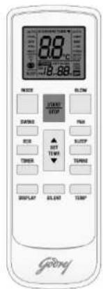
Names and functions of wireless remote control
Note: Be sure that there are no obstructions between the receiver and the remote hand set, Don't drop or throw the remote hand set. Don't let any liquid in the remote control and don't put the remote control directly under the sunlight or any place which is very hot.
Remote Hand Set

SLEEP button
By pressing this button, Sleep On and Sleep off can be selected. By default, the function will get cancelled automatically in eight hours. After sleep function is set up, the icon of 'Sleep' will be displayed. This function is only available in COOL mode.
FAN button
By pressing this button, Low, Middle, High & Auto, speed can be circularly selected.
Start/Stop button
Press this button to turn on/ switch off the unit. While turning on or switching off the AC, the Timer, Sleep Function 'Etc. will be canceled.
MODE button
Press this button to select from Auto, Cool, Dry and Fan Mode. Under Cool/Dry mode, If user set the temperature below 24 degree in prior to switching off AC and then if AC is turned on by Remote, AC will start operating at 24 degree temperature only. If user set the temperature 24 degree or above 24 degree in Cool/Dry mode prior to switching off AC and then if AC is turned on by Remote, AC will start operating at previous set temperature by user.
NOTE: Please do not select HEAT mode if the machine you purchased is cooling only type. Heat mode is not supported by the cooling only appliance.
If any of the key is pressed for more than 2 secs, the backlight of LCD remote handset will turn ON for 8secs.
NOTE: Under the Dry mode, the fan speed isn't adjustable. Low fan speed is imperative.
REMOTE CONTROLLER (INVERTER AC)
Names and functions of wireless remote control
DISPLAY button
Press this button to clear the digit display on the air conditioner. Press it again to activate it (Not available for the units without LED display window).
Remote Hand Set
TURBO button
Push this button to activate/cancel the Turbo function which enables the unit to reach the preset temperature in the shortest time. On cooling mode, the unit will blow strong cold air with super high fan speed. By default, this function will get canceled in one hour.
Up button
Press this button, to increase the temperature, when unit is on. In AUTO, DRY and FAN mode the temperature cannot be set. Centigrade scale range is from 16°C - 31°C.
This button is also used for setting time while duringTIMER operation.
Down button
Press this button, to decrease the temperature, when unit is on. The temperature adjustment is unavailable in the AUTO, DRY and FAN mode.
This button is also used for setting time while using TIMER operation.
BLOW button
If bad odor is coming from the air conditioner, press BLOW button on the remote handset. This function will keep the indoor fan running at super high fan speed for 5 minutes, after this the air conditioner is turned OFF. The indication of minutes will be displayed on the displayer.
Note: It is recommended to use BLOW function when AC is OFF.
This function helps to keep the indoor coil dry and prevent dust and mold accumulation. Also the growth of bacteria in indoor coil due to moisture reduction.
REMOTE CONTROLLER (INVERTER AC)
Names and functions of wireless remote control

Remote Hand Set
TIMER button
Press this button to initiate auto ON and auto OFF time sequence. Each press will increase the auto timed setting with 1 hour increment. To set the time use up and down keys.
- If you pressed TIMER button when AC is ON and set the time using remote handset, the AC will turned OFF after the set time duration is completed.
- And if you pressed the TIMER button when the AC is OFF and set time using remote handset, the AC will turned ON after the set time duration is completed.
ECO button
This button is nominated by Eco on remote control unit. It "energy consumption reduced" when Eco mode function is set to air-conditioner (indoor unit) for reduces the power consumption and prevent overloading. It only operates in cool mode.
On LCD display of remote control unit along with 24 degree temperature, Low fan speed in COOL mode operation of on condition of RCU and here can't varies the temperature.
Press again Eco button for stop the energy saver function.
On LCD of remote control unit, recall the previous setting of remote control
SWING UP AND DOWN BUTTON

Press this button to turn on/off the louver movement.
When IDU swing louver is ON, will appear on remote control and When Indoor swing is OFF, will not appear on the remote.
SILENT button
Press this button to enable or disable silent function where indoor fan will run on lowest speed to provide comfortable silent operation.
REMOTE CONTROLLER (INVERTER AC)
Guide for operation - General operation
- After Switching ON the power supply, press ON/OFF button, and the unit will start to run. (Note: When AC is power off using remote handset, the guide louver of the indoor unit will close automatically.)
- Press MODE button to select the desired running mode, or press COOL mode to enter into the corresponding operation directly.
- Press up and down button, to set the desire temperature. (Setting temp. function is cancelled in AUTO, DRY and Fan Mode)
- Press FAN button to set fan speed and can select among low, medium, high and auto.
- Press Swing (up-down) button, to select the swing.
Guide for operation – Optional operation
- Press SLEEP button, to set sleep.
- Press TIMER button, to set the scheduled timer on or timer off.
- Press DISPLAY button, to switch the display on the indoor unit on or off. (This function may be not available for some units)
- Press TURBO button, to set the TURBO function ON and OFF


REMOTE CONTROLLER (INVERTER AC)
Guidelines for Changing batteries
Lightly press the location marked , along the arrowhead direction to push the back cover of wireless remote hand set. (As show in figure)
Take out the old batteries. (As show in figure)
Insert two new AAA1.5V dry batteries, and pay attention to the polarity. (As show in figure)
Replace the back cover of wireless remote hand set. (As show in figure)
NOTE:
When changing the batteries, do not use the old or different batteries, otherwise, it can cause the malfunction of the wireless remote control.
If the wireless remote control will not be used for a long time, please take them out, and don't let the leakage liquid damage the wireless remote control.
It should be placed at least 1m away from the TV set or stereo sound sets.
If the wireless remote hand set is not functioning normally, take out the batteries, and after 30s reinsert them. If they are still not running normally replace them.
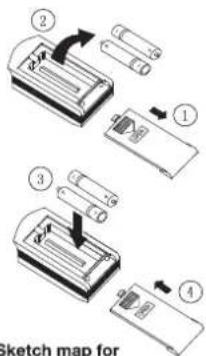
Sketch map for changing batteries
REMOTE CONTROLLER (FIXED SPEED AC)
GENERAL FEATURE:
The Controller has following features--
• Display: Dual digit display with Led Indicators.
- Preset temperature setting from 16°C to 31°C.
• Compressor delay protection.
• Different fan speed i.e. Low, Medium, High and Auto.
- Timer can be set in hour to turn ON/OFF the machine.
• Memory backup in case of power failure.

REMOTE:
REPLACEMENT OF BATTERIES

Remote Controller 1
- When the signal from the remote controller becomes weak and the indoor unit can not receive it properly; or the indications on the display screen becomes blurred, please slide the back cover and replace with two new batteries.
- The positive and negative poles must match the installation positions.
- New batteries of the same type have to be used for replacement.
- If the remote controller is not to be used for long time, take out the batteries so as to prevent the leakage of the electrolyte from damaging the controller.
- If when the remote controller is at abnormal state, you can take out the batteries on the back cover to clear off the display.
OPERATING MODE (INVERTER AC)
AUTO Mode:
- Press 'MODE' button to cyclically step through the AUTO→COOL→DRY→FAN modes and stop when AUTO mode is selected.
● AUTO will appear on the remote display when you select the AUTO mode. - The air conditioner will automatically select cooling, or fan only operation depending on set temperature and the room temperature.
- Setting temperature cannot be changed. By default it will set to 25°C and display on indoor panel. In this mode the fan speed is changeable (Low, Medium, High, and AUTO)
COOL Mode:
- In the cool mode, the compressor is in operation and your AC functions in the standard operating mode, cooling your room to desired set temperature.
- Press 'MODE' button to cyclically step through the AUTO→COOL→DRY→FAN modes and stop when COOL mode is selected.
- The cooling function allows air conditioner to cool the room and at the same time reduces the humidity in the air. In this mode the compressor will run at different frequencies depending on difference between set temp. and room temp. which gives you faster cooling as compared to fixed speed AC.
- Setting temperature range is 16°C to 31 °C. The ideal temperature that can be set for comfort and energy savings is between 21°C to 25°C depending whether it is day or night.
- You can change the fan speed setting by pressing FAN button .(Low , Medium, High, and AUTO)
- TURBO, SLEEP, and ECO functions are only available during cooling mode.
Dry Mode:
- In the DRY mode, air conditioner reduces the humidity of the air to make the room more comfortable.
- Press 'MODE' button to cyclically step through the AUTO→COOL→DRY→FAN modes and stop when DRY mode is selected.
- DRY can be seen on the remote panel when you select the DRY mode.
- The indoor fan runs at low speed and compressor frequency will vary according to the difference between set and room temperature just to remove extra humidity. In this mode the air conditioner does not blow a lot of cool air, as the intent is just to dry the air and not to cool the room.
- Set temperature and fan speed cannot be change as indoor fan speed is restricted to Low. Indoor display will show the set temp.
OPERATING MODE (INVERTER AC)
Fan Mode:
- Press 'MODE' button to cyclically step through the AUTO→COOL→DRY→FAN modes and stop when FAN mode is selected.
● FAN can be seen on the remote panel when you select the FAN mode. - In this mode compressor and outdoor fan are off and indoor fanspeed can be varied between Low, Medium, High, speed using remote control.
● Indoor unit displays the indoor room temperature.
REMOTE CONTROLLER (FIXED SPEED AC)
I/O ON/OFF
Press this key to turn the machine on/off. The AC always starts with the previous settings.
FAN
Pressing this key, Fan speed will change in Low - Medium -High -Auto fan speed sequence. Auto speed can be set only in cool mode. In Auto speed operation, fan speed will be controlled automatically based on the difference between the set and room temperature. If the user feels uncomfortable due to auto Fan operation, he can switch to manual selection of fan speed.
MODE
Select Auto, Cool, Dry, Fan and Heat function by using mode key. (Heat mode will be applicable for heat cool series models only).
Note :- Under Cool/Dry mode, If user set the temperature below 24 degree in prior to switching off AC and then if AC is turned on by Remote, AC will start operating at 24 degree temperature only. If user set the temperature 24 degree or above 24 degree in Cool/Dry mode prior to switching off AC and then if AC is turned on by Remote, AC will start operating at previous set temperature by user.
UP/DOWN
Set Temperature and timer value can be increased/decreased by using this key
VERTICAL SWING
Using this key, swing positions change accordingly. Swing enable or disable can also be set.
HORIZONTAL SWING
Applicable for horizontal swing series models.
TIMER
Press this button to initiate auto ON and auto OFF time sequence. Each press will increase the auto timed setting in 1 hour increments. To set the time use up and down keys.
If you pressed TIMER button when AC is ON and set time using remote handset, the AC will turned OFF after set time duration is completed.
And if you pressed TIMER button when AC is OFF and set time using remote handset, the AC will turned ON after set time duration is completed.
SLEEP
Sleep function can be set in cool mode & *Heat mode, it can enabled or disabled by pressing this key.
TURBO
Turbo feature can be operated by pressing turbo key. Enabling turbo key will set the fan speed at turbo.
LAMP
By pressing this button, you can turn ON and OFF AC display.
- Whenever Lamp function is enabled, display will go off except function indicator.
ii. When Lamp is enabled, if user presses the temperature up/down key, the display will be on for 5 second, from the time the key was last pressed.
ECO
ECO button is used to activate/ deactivate ECO feature. When ECO button on remote is pressed, default set temperature will be 24 degree on remote and Fan speed will be set to Auto fan speed.
In cool mode Condition: On IDU Display, set temperature+2 degree temperature will be displayed. In heat mode Condition: On IDU Display, set temperature-2 degree temperature will be displayed.
TEMP
If user presses the TEMP key. Room temperature will appear on the IDU display for 5 second.
SILENT
Helps in silent operation of Air Conditioner.
OPERATING MODE (FIXED SPEED AC)
OPERATING MODES :
1. AUTO MODE :
- The AC automatically selects the mode in which it should run by judging the difference in the ambient temperature and the set temperature.
• In Auto mode Temperature can't be changed.
2. COOL MODE:
• In cool Mode set temperature is adjustable between 16 Degree to 31 Degree C.
• Indoor fan will run at selected fan speed.
3. DRY MODE :
• This mode removes excess humidity from the room.
• Display : In dry mode, display will show Preset temperature.
• Fan speed can't be changed.
4. HEAT MODE:
• In Heat Mode set temperature is adjustable between 16 Degree to 31 Degree.
• Indoor fan will run at selected fan speed.
5. FAN MODE :
• Indoor fan will run at selected speed.
• Compressor will be off in fan mode.
DISPLAY FEATURE :
Seven Segments Display: Preset temperature will appear for all the time on the Display but if user presses the TEMP key then ROOM TEMP. will appear for 5 second on IDU Display and after that again SET TEMP. will appear on it. While the room temp. appears on the display, if user presses the temp up/down key, set temp. will appear on the display and feeling get disabled.
PROTECTION FEATURES :
• Sensor Fail Protection
• Defrost Protection in cool mode.
• Defrost Protection in heat mode.
• Fan Motor Protection
SENSOR PROTECTION :
- When the Room sensor is short or open :
- Display will show "E1" and Set Temp. Intermittently.
• When the Evaporator Coil Sensor short or open : - Display will show "E2" and "Set Temp." Intermittently.
- When the Condenser Coil Sensor short or open :
- Display will show "E3" and "Set Temp." Intermittently.
IDU FAN MOTOR PROTECTION :
- In case of fan error display will show "H6". Compressor & fan will turn off immediately.
IF IT HAPPENS, IT IS NOT A PROBLEM
| If it happen | It is not a problem |
| The unit does not operate | Due to high (>280) or low (<140) voltage, it has gone into protection mode and thus stopped.* |
| Less cooling | Check whether unit is working in dry mode? |
| The unit does not respond to commands | Check whether LOCK key is activate or not? |
| The indoor display is off | Activate DISPLAY key on remote control |
| If you select 0.5(half hour)timer but IDU display shows 1 (one hour) | Dual digit display limitation. It can't display 0.5, it will display 1 for both Half and one hour.* |
| After AC is switched off, if indoor display shows '05' | It may happen that you have selected the BLOW function when AC was ON, and therefore AC is performing BLOW operation after it turned OFF. |
| If you set indoor fan speed at low speed, but sill it is working at high speed | 3 min. delay when fan speed changed from high to low.* |
*for inverter models.
DC INVERTER TESTING PROCEDURE
Applicable only for Inverter Models
Full Load Cooling testing procedure
- To enable the test mode, switch on the Unit and set it to "Cooling" Mode.
- Set temp. as "16°C" and fan speed to "High".
- Press Display Key from remote 6 times continuously within 10 Seconds
- As the test mode gets enable, twice buzzer sound will come with whole LED light panel lights up and starts blinking on indoor display.
Details set temperature and operating conditions information as below
| Cooling condition | Setting temperature | Description | |
| Indoor | Outdoor | ||
| 27/19 | 35/24 | 16°C | Full Load Cooling |
Half Load Cooling testing procedure
- To enable the test mode, switch on the Unit and set it to "Cooling" Mode.
- Set temp. as "17°C" and fan speed to "High".
- Press Display Key from remote 6 times continuously within 10 Seconds
- As the test mode gets enable, twice buzzer sound will come with whole LED light panel lights up and starts blinking on indoor display.
Details set temperature and operating conditions information as below
| Cooling condition | Setting temperature | Description | |
| Indoor | Outdoor | ||
| 27/19 | 35/24 | 17°C | Half Load Cooling |
Note : On power reset, controller will come out from the test mode and will run in normal operation. To enter in test mode, user has to again follow the procedure from point 1 in both load condition.
PROTECTION
Inverter Operation :-
Air conditioner automatically calculates the heat load and accordingly it delivers the cooling inside the room, to bring down the temperature equal to set temperature and maintain the comfort temperature at less energy consumption.
In case of any fault in inverter outdoor unit the operation of air conditioner will get stop immediately and corresponding error will appear on the indoor display.
ERROR CODE :- APPLICABLE ONLY FOR INVERTER MODELS
| Sr. No. | UNIT TYPE | ERROR CODE | ERROR CODES DESCRIPTION |
| 1 | IDU | EE | Indoor machine EE fault |
| 2 | E1 | Indoor fan fault | |
| 3 | E2 | Indoor Fan Zero-crossing detection abnormal | |
| 4 | E3 | Indoor coil sensor fault | |
| 5 | E4 | Indoor ambient temperature sensor fault | |
| 6 | E6 | Indoor and outdoor machine communication fault | |
| 7 | ODU | E0 | Outdoor EE fault |
| 8 | E8 Outdoor communication fault | ||
| 9 | F1 | Compressor starting abnormal (phase failure, reverse) | |
| 10 | F2 | Compressor out-of-step fault | |
| 11 | F3 | IPM module fault | |
| 12 | F4 | Compressor shell roof fault/protection | |
| 13 | F5 | Discharge temperature sensor fault | |
| 14 | F6 | Suction temperature sensor fault | |
| 15 | F7 | Outdoor coil temperature sensor fault | |
| 16 | F8 | Outdoor ambient temperature sensor fault | |
| 17 | F9 | Outdoor DC fan fault | |
ERROR CODE :- APPLICABLE ONLY FOR FIX SPEED MODELS
| ERROR SIGNALS ON THE DISPLAY | |
| Code | Error Description |
| H6/E5 | IDU Fan Motor Protection |
| dF | Frost Protection |
| E1 | Room Sensor Error |
| E2 | Evaporator Sensor Error |
| U8* | Zero Cross Detection |
| E3* | ODU Coil Sensor Error (in Heat Mode) |
| HF* | ODU Frost Protection (in Heat Mode) |
| HP* | IDU Coil Over Heat Protection (in Heat Mode) |
| * For selected models only ACI1PR03202 | |
CLEAN AND CARE
Front panel
1. Remove the front panel.
- Open the front panel.
- Slide the front panel to either the left or right and pulling it toward you.
This will disconnect the front panel shaft on one side.
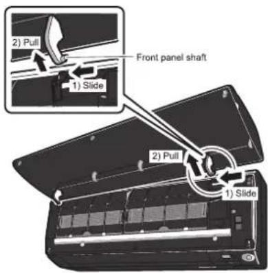
- Disconnect the front panel shaft on the other side in the same manner.

natural_image
Interior view of a black appliance showing internal components and airflow arrows (no text or symbols)2. Clean the front panel.
- Wipe it with a soft cloth soaked in water.
- Only neutral detergent may be used.
- In case of washing the panel with water, wipe it with dry soft cloth, dry it up in the shade after washing.
3. Attach the front panel.
- Align the front panel shaft on the left and right of the front panel with the slots, then push them all the way in.
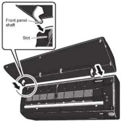
- Close the front panel slowly. (Press the panel at both sides and the central area.)

CAUTION
- When removing or attaching the front panel, use a robust and stable stool and watch your steps carefully.
- When removing or attaching the front panel, support the panel securely with hand to prevent it from falling.
After cleaning, make sure that the front panel is securely fixed.
CLEAN AND CARE
Air filter
1. Pull out the air filters.
- Open the front panel.
- Push a little upwards the filter tab at the center of each air filter, then pull it down.
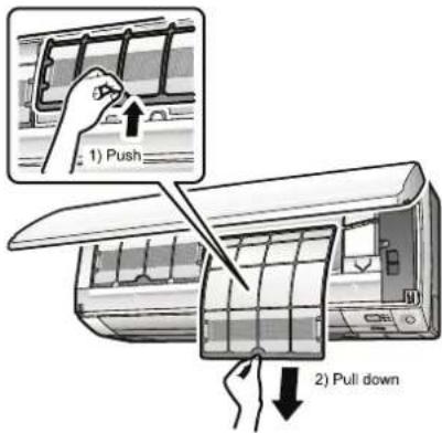
2. Wash the air filters with water or clean them with vacuum cleaner.
- It is recommended to clean the air filters every 2 weeks.

natural_image
Illustration of two hands holding a grid-based object with a tool, no text or symbols presentIf the dust does not come off easily
- Wash the airfilters with neutral detergent thinned with lukewarm water, then dry them up in the shade.

3. Set the filters as they were and close the front panel.
- Press the front panel at both sides and the central area.

natural_image
Illustration of a wall-mounted air conditioner unit with airflow arrows indicating airflow direction (no text or symbols)
CAUTION
- Do not touch the aluminum fins by bare hand at the time of dismounting or mounting the filter.
CLEAN AND CARE
ò Check the units
- Check that the base, stand and other fittings of the outdoor unit are not decayed or corroded.
- Check that nothing blocks the air inlets and the outlets of the indoor unit and the outdoor unit.
- Check that the drain comes smoothly out of the drain hose during COOL or DRY operation.
- If no drain water is seen, water may be leaking from the indoor unit. Stop operation and consult the service shop if this is the case.
ò Before a long idle period
- Operate the "FAN only" for several hours on a fine day to dry out the inside.
- Press MODE and select "♣" operation.
Press □ and start the operation.
- After operation stops, turn off the breaker for the room air conditioner.
- Clean the air filters and set them again.
- Take out batteries from the remote controller.
- When a multi outdoor unit is connected, make sure the heating operation is not used at the other room before you use the fan operation.
- We recommend periodical maintenance
- In certain operating conditions, the inside of the air conditioner may get foul after several seasons of use, resulting in poor performance. It is recommended to have periodical maintenance by a specialist aside from regular cleaning by the user.
- For specialist maintenance, contact the service shop where you bought the air conditioner.
• The maintenance cost must be born by the user.
MAINTENANCE
| Item | Cleaning interval | Cleaning method |
| Dust filter | 2 Weeks | See “Cleaning Dust filter.” |
| Anti-Bacterial filter* | 3 Months | See “Anti-Bacterial filter.” |
| Indoor Unit | Regularly | Clean the Indoor unit surface by using a soft, dry Cloth. |
| Every 4 Months | Clean the condensate drain pipe. | |
| Once a year | Clean the condensate drain pan. | |
| Once a year | Throughly clean the heat exchanger. | |
| Once a year | Replace the remote control batteries. | |
| Outdoor Unit | Regularly | Use steam to clean the heat exchanger coils and the panel vents. (consult with technician) |
| Once a year | Clean the fan. | |
| Once a year | Clean the condensate drain pan. | |
| Once a year | Verify that all the fan assembly is firmly tightened. | |
| Once a year | Clean the electric components with air. |
TROUBLESHOOTING

CAUTION
Don't attempt to repair the air conditioner by yourself, it can cause an electric shock or fire. Please check the following items before asking for repair, it can save your time and money.
| Phenomenon | Troubleshooting |
Does not operate immediately when the air conditioner is restated.  | ● Once the air conditioner is stopped, Compressor will take approx. 3 minutes to restart. |
There's unusual smell blowing from the outlet after operation is started. | ● The unit has no peculiar smell by itself. If has, that is due to the smell accumulated in the ambient.● Solution method: Cleaning the filter. If the problem still persists, so need to clean air conditioner. (Please contact with the authorized maintenance center.) |
Sound of water flow can be heard during the operation.  | ● While air conditioner is running for while the compressor get started or stopped, Refrigerated sound can be heard.● This is a normal function. |
In COOL mode, sometimes the mist emitted from the air outlet vent. | ● When the indoor temperature and humidity are very high, this phenomenon would happen. This is caused by the room air is swiftly cooled down. After running for a while, indoor temperature and humidity will fall down, the mist will go away. |
Creaking noise can be heard when start or stop the unit.  | ● This is caused by the deformation of plastic due to the changes in temperature. |
TROUBLESHOOTING
| Phenomenon | Troubleshooting | |
| The unit does not run. | Has the power been shut down?Is the power plug loose?Is the circuit protection device tripped off or not?Is voltage higher or lower?(Tested by professionals)Is the TIMER correctly used? | |
 |  | |
| Cooling(Heating) efficiency is not good. | Is Temp. setting suitable?Were inlet and outlet vents obstructed?Is filter dirty?Are the windows and doors closed?Was Fan speed set at low speed?Is there any heat sources in the room? | |
 |  | |
| Wireless remote control is not available. | The unit is interfered by abnormal or frequent functions switchover occasionally the controller cannot operate. At this time, you need to pull out of the plug, and reinsert it.Is it in its receiving range? Or obstructed?check the batteries is charged, otherwise to replace the batteries.Whether the wireless remote control is damaged. | |
 |  | |
| If water leakage in the room. | The air humidity is on the high side.Condensing water over flowed.The connection position of indoor unit drainage pipe is loosed. | |
| If water leakage in outdoor unit. | When the unit is running in COOL mode, the pipe and connection of pipe would be condensed due to the water cooled down.When the unit is running in Auto Defrosting mode the ice thaws and flows out.When the unit is running in HEAT mode, the water adhered on heat exchanger drips off. | |
| Noise from indoor unit emitted. | The sound of fan or compressor relay is switching on or off.When the defrosting is started or stop running, it. That is due to the refrigerant flowed to the reverse direction. Can be the sound of fan on the compressor,switching on and off while defrostin g, as the refrigerant flows in the opposite direction. | |
TROUBLESHOOTING
| Phenomenon | Troubleshooting |
| Indoor unit does not blow air. | In HEAT mode, when the temperature of indoor heat exchanger is very low, that will stop deliver air in order to prevent cool air. (Within 2min) |
| (* Applicable for Heat Cool models only.) | In HEAT mode, when the outdoor temperature is low or high humidity, there are much frost formed on the outdoor heat exchanger, that the unit will automatically defrost due to which, indoor unit stop blowing air for 3-12min.During the defrosting, there is water flowing out or vapor be produced.In dehumidifying mode, sometimes indoor fan get stop, in order to avoid condensing water be vaporized again, to restrain temperature from rising. |
| Moisture on air outlet vent. | If unit is running under the high humidity for a long time, the moisture will be condensed on the air outlet grill and drip off. |

Immediately stop all operations and plug out, contact the dealer in following situations.
There is harsh sound during operation.
The terrible odour emitted during operation.
Water is leaking in the room.
Air switch or protection switch often breaks.
Carelessly splash water or something into unit.
There is an abnormal heat in power supply cord and power plug.
Stop running and pull out of the plug.
INSTRUCTION FOR INSTALLATION
【Selection of installation positions for indoor unit】
● To be installed at the position where the air delivered from the unit can reach every corner of the room;
● To avoid being affected by the outdoor air;
● To avoid blockage to the air inlet or outlet of the unit;
● To avoid too much oil smoke or steam;
● To avoid possible generation, inflow, lingering or leakage of flammable gases;
● To avoid high-frequency facilities (such as high frequency arc welders, etc.);
● To avoid the places where acid solutions are frequently used;
● To avoid the places where some special sprayers (sulfides) are frequently used.
● Not to install on top of the musical instruments, TV, computer etc. valuable appliance.
● Not to install a fire alarming device near the air outlet of the unit (during operation, the fire alarm device might be erroneously triggered by the warm air from the unit);
■ Make sure of enough space for installation and maintenance.
● To take into consideration the operational convenience and safety in installation, it is recommended to ensure enough space between the unit and the walls.

Attention: If there are some additional function devices to install on the air conditioner, Be sure add to the installation space for the function devices.
■ Height limits of indoor and outdoor units.
● Either the indoor unit or the outdoor unit can be higher, but the height difference must comply the stated requirements.
● Try to reduce the bending of the piping line as much as possible so as to avoid possible negative impacts upon the performances of the units.
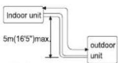
If indoor is at more height

If outdoor is at more height
INSTRUCTION FOR INSTALLATION
【Selection of installation positions for outdoor unit】
● To install the outdoor unit at the places which can stand the load of the machine weight and will not cause big vibrations and noises;
● To install the unit at the places not to be exposed to rain or direct sunshine, and the places with good ventilation;
● The noises generated from the unit will not affect the neighboring places;
- Do not install the unit on non-metal frame;
● Not to install the unit at the places where there might occur the generation, inflow, stay or leakage of inflammable gases;
● Pay attention to the drainage of the condensed water from the base plate during operations;
● To avoid the air outlet being directly against the wind.
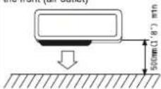
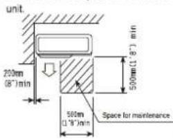
Detailed space requirements around the outdoor unit
- When there are obstacles above the unit
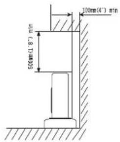
- When the front (air outlet) is open

- When there are obstacles at the front and rear sides.

- When there are obstacles only in the front (air outlet)
Space for maintenance
Shown as in the following figure. Keep the maintenance space in front of the
- When there are obstacles all around the unit on four sides.
Although the top side is open, the installation is not to be done if there are obstacles all around.

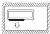
● At least two sides should be kept open.
INSTRUCTION FOR INSTALLATION
【Installation fixture of indoor unit】
Pipelines can be connected in the directions of ①、②、③ and ④ as indicated in Fig.1. When the pipelines are connected to the directions of ③ and ④, a groove for the pipes has to be opened at the proper place on the base stand.

1. Installation of wall-mounting plate
Fix the wall-mounting plate firmly on the wall with screws. Make sure of the leveling of the plate. Slanted wall-mounting plate might jeopardize the smooth discharge of the condensed water.
2. Drill holes on the wall
Drill holes at places slightly below the wall-mounting plate, with hole diameter of 65mm(2-3/5") and the outer edge of the hole 5-10mm(1/5-2/5") lower (Fig.2) so that the condensed water can smoothly flow out. Cut the wall penetrating pipe to proper length according to the thickness of the wall (3-5mm(1/10-1/5") longer than the wall thickness) and insert the pipe as indicated in Fig.2.

3. Installation of drain pipe
Install the pipelines of the indoor unit in accordance with the direction of the wall holes. Wrap tightly the drain pipe and the pipelines with tape. Make sure that the drain pipe is underneath the pipelines. (Fig.3) (When the drain pipe passes the room interior, some condensed water might occur to its surfaces if the humidity is very high).

4. Installation of indoor unit
Pass the connection wires, connecting pipelines and drain pipe through the wall hole. Hang the indoor unit on the hooks at the top of the wall-mounting plate so that the hooks at the bottom of the indoor unit match the hooks of the wall-mounting plate. (Fig.4)


For Right side piping

For Left side piping
INSTRUCTION FOR INSTALLATION
Inspections:
a. Check if the hooks at the top and bottom are firmly fixed.
b. Check if the position of the master unit is properly leveled.
c. The drain pipe should not curve upward (Fig.5).
d. The drain pipe should be at the lower part of the wall pipes (Fig. 5).
Fig.5

【Installation fixture of outdoor unit】
● Try to ship the product to the installation location in its original package;
● As the gravity center of the unit is not at the installation center, special caution should be taken when using hoisting cables to lift it up;
● During shipping, the outdoor unit must not be slanted to over 45 degrees (Do not store the unit in a horizontal way).
● Use expansion bolts to fix the mounting supports on the wall;
- Use bolts and nuts to fix the outdoor unit firmly on the supports and keep on the same level;
- If the unit is installed on the wall or at the rooftop, the supports have to be firmly fixed so as to resist earthquake or strong wind.
Dimensions for parallel units installations
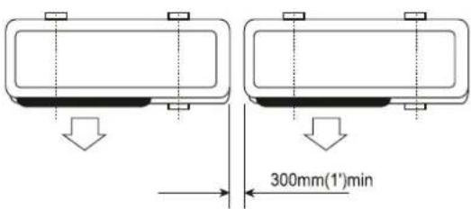
【Ordinary pipelines connection & Air purging】
● The following ordinary pipelines connection and air purging procedures are just suitable for non-quick coupler model.
■ Ordinary pipelines connection
No dust, foreign articles, air or moisture should be allowed to enter the air conditioning system. Careful attention should be paid when pipeline connection for outdoor unit is made. Try to avoid repeated curves as much as possible, otherwise hardening or cracks might be caused to the copper pipes. Suitable wrenches should be used when the pipeline connection is done so as to ensure appropriate torque (refer to following torque Table 1). Excessive torque might damage the joints while too little torque might lead to leakage.
INSTRUCTION FOR INSTALLATION
Table 1 Torque based upon the wrench to be used
| Outer diameter of copper pipe | Tightening torque | Strengthened tightening torque |
| ∅ 6.35(1/4") | 160kgf.cm(63kgf.inch) | 200kgf.cm(79kgf.inch) |
| ∅ 9.52(3/8") | 300kgf.cm(118kgf.inch) | 350kgf.cm(138kgf.inch) |
| ∅ 12.7(1/2") | 500kgf.cm(197kgf.inch) | 550kgf.cm(216kgf.inch) |
| ∅ 15.88(5/8") | 750kgf.cm(295kgf.inch) | 800kgf.cm(315kgf.inch) |
| ∅ 19.05(3/4") | 1200kgf.cm(472kgf.inch) | 1400kgf.cm(551kgf.inch) |
■ Air purging with vacuum pump
- Check that pipelines connection have been properly connected, remove the charging port cap, and connect the manifold gauge and the vacuum pump to the charging valve by service hoses as shown Fig.6.
2.Open the valve of the low pressure side of manifold gauge, then, run the vacuum pump. Vacuum the indoor unit and the connecting pipes until the pressure in them lowers to below 1.5mmHG(The operation time for vacuuming is about 10 minutes). When the desired vacuum is reached, close the valve of the low pressure of the manifold and stop the vacuum pump. - Disconnect the service hoses and fit the cap to the charging valve.
- Remove the blank caps, and fully open the spindles of the 2-way and 3-ways valves with a service valve wrench.
- Tighten the blank caps of the 2-way and 3-ways valves, applying the above torque Table 1.
■ Adding refrigerant
Refrigerant must be added if the piping measures more than 5 metres(16'5") in length. This operation can only be performed by a professional technician, for the additional amount, see the table 2 below.
Table 2
| Additional refrigerant amount | |
| Liquid pipe diameter ∅6.35(1/4") | Liquid pipe diameter:∅9.52(3/8") |
| (piping length-5)mx30gor (piping length-16)ftx0.3oz | (piping length-5)mx65gor (piping length-16)ftx0.7oz |
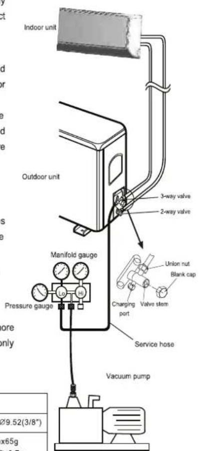
Fig.6
INSTRUCTION FOR INSTALLATION
Gas leakage inspection
After the pipeline connection is done, use a leakage inspection device or soap suds to carefully check if there is any leakage at the joints. This is an important step to ensure the quality of installation. Once a leakage is detected, proper treatment should be taken immediately.
Applicable for coupler series model.
【Pipelines connection for Split type quick coupler model】
- If you purchase the machine for split type quick coupler model, please adopt the following pipeplines connection procedures:
- Remove the dust caps from the indoor and outdoor units, and the connecting pipe.
-
Align the joint counter of connecting pipe with the proper indoor and outdoor joint conic surfaces, tighten the connecting nut manually. Then, make it secure with a wrench as shown Fig.7, applying to above torque Table 1.
-
Remove the two valve core caps from the outdoor unit.
-
Turn on the high and low pressure valve cores with an socket wrench, then tighten the two valve core caps of the outdoor unit (Fig.8).
-
Finally, wrap the hot insulating cotton around the joints of indoor and outdoor units.

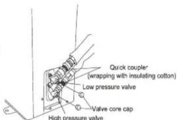
Fig.8
● Notes on installation of quick coupler:
- Connecting pipe bending minimum radius parameters (Table 3)
- Quick coupler assembly and disassembly limit: the assembly and disassembly times are inadvisably more than 7.
Table 3 Minimum bending radius
| Normal diameter(mm) | Minimum bending radius(mm) | cooling capacity |
| DN8(5/16") | 80(3") | 2100-2300W (7000-8000BTU) |
| DN10-12 (1/2") | 100(4") | 2500-5100W (9000-18000BTU) |
| DN14-16 (5/8") | 150(6") | 6100-7000W (22000-24000BTU) |
INSTRUCTION FOR INSTALLATION
【Is the unit installed correctly?】
Suitable Installation Position
- Isn't there anything which prevents ventilation or obstructs operation in front of the indoor unit? Do not install the unit following place.
• Inflammable gases may leak. - Oil splashes a lot.
- In case where the unit is used in such places as poisonous or sultry gases are generated or seaside district exposed to sea breezes corrosion may cause malfunction. Consult with your distributor.
- Air conditioner body and remote controller must be 1mtrs. (39-3/4") or more away from a TV or a radio. Drain the dehumidified water from the indoor unit to a place which drains well.
■ Pay attention to operation noise
- When installing the unit, choose a place which can stand the weight of the unit well and does not increase the operation noise or vibration. Especially where there is a possibility that vibration be transmitted to the house, fix the unit by inserting attached vibration -proof pads between the unit and fittings.
- Choose the place where hot air and operation noise from the outlet of the outdoor unit do not annoy the neighborhood.
- Things left near the outlet and inlet of the outdoor unit cause malfunction or increased operation noise. Do not leave obstacles near the outlet and inlet.
- If irregular sound is heard during operation, consult with your distributor.
■Inspection and Maintenance
- According to the service conditions and operating environment, the inside of the air conditioner will become dirty after several seasons (3 to 5 years) of service, resulting in decreased operating performance. Inspection and maintenance are recommended in addition to usual cleaning (The air conditioner can be used for a longer period and without anxiety.)
- As to inspection and maintenance, consult your dealer or any one of business offices of dealing companies. (Service charge is required in this case.)
- We recommend to perform inspection and maintenance during an off seasons.
SERVICE CENTRE
| GODREJ & BOYCE MFG. CO. LTD., Appliances Division | |
| Branch | Address |
| Ahmedabad | 4th Floor, APM Shopping Mall Near IOCL Petrol Pump, Shyamal-Karnavati, 100 ft. Road, Satellite, Ahmedabad - 380 015 |
| Bangalore | 3rd Floor, The Karnataka Film Chamber of Commerce Bldg. 28, 1st Main,Crescent Road, High Grounds Nr. Shivanand Circle, Bangalore - 560 001 |
| Bhopal | 217, Zone I, M.P. Nagar, Beh. Jyoti Talkies, Bhopal - 462 011 |
| Bhubaneshwar | Highway Complex, NH-5, Rudrapur, Bhubaneshwar - 752 101 |
| Chandigarh/Mohali | Plot No. A-40, Phase VIII-A, Industrial Area, Mohali - 160 059 |
| Chennai | No. 1, Sidco Industrial Estate, Ambattur, Chennai - 600 098 |
| Coimbatore | No. 585 - 590 3rd Floor, Sathya Towers, DB Road, R S Puram, Coimbatore- 641002 |
| Delhi | Godrej Bhavan, 2nd Floor, Shershah Suri Marg, Mathura Road, Okhla,New Delhi - 110 065 |
| Faridabad | Godrej Bhavan, 2nd Floor, Shershah Suri Marg, Mathura Road, Okhla,New Delhi - 110 065 |
| Ghaziabad | Plot No. 229/230, Sardar Pashu Ahaar, Bulandshahar Road, Village-chaprolla, Ghaziabad |
| Guwahati | Basundhara Enclave, 1st & 2nd Floor Ulubari, Guwahati 781007 |
| Hyderabad | 201 & 202, Lala-1 Land Mark, 5-4-94 to 97, 2nd Floor, Above DigitalShoppy, Ranigunj, M.G. Road, Secunderabad -500 003 |
| Jaipur | 502-506, 5th Floor, Gaurav Towers, Malviya Nagar, Jaipur - 302 017 |
| Kochi | 2nd floor, Angels Arcade, South Kalamasserry, Near CUSAT PO Kochi682022 |
| Kolkata | Plot-30, Block-GN, Sector-V, Salt Lake city, Kolkata - 700 091 |
| Lucknow | C-3/3 & C-3/4, Sanjay Complex, Near All India Radio, Vidhan Sabha Marg,Lucknow-226001 |
| Mumbai | Appliance Division, Plant 4, Pirojshahnagar, Vikhroli, Mumbai - 400 079 |
| Nagpur | Dr. Bhiwapurkar Chamber, 2nd Floor, Opp. Yashwant Stadium, Dhantoli,Nagpur - 440 012 |
| Patna | Grand Plaza 6th Floor, 6001-6004, Dakbunglow Crossing. Frazer Road.Patna-800001 |
| Pune | Apollo Building Square, Plot No. 60, Survey No. 599, Sahaney Sujan Park,Lullanagar, Bibewadi Road, Pune - 411 040 |
| Raipur | 9/1, Besides Bharat Petrol Pump, Opp, Hotel Picadelly, Mahoba Bazaar,G.E. Road, Raipur - 492 001, Chhatisgarh |
| Ranchi | C/o. Surya Motors, Near Krishi Bazaar Samiti Panda, Ranchi (Jharkand) -835 222 |
| Toll-Free :1800-209-5511 | |
| Website: www.godrejappliances.com & www.godrejsmartcare.comE-mail: smartcare@godrej.com | |
WARRANTY AIR CONDITIONER
The Godrej Air Conditioner comes with a FIVE year warranty on compressor for fixed speed Air conditioners and TEN year warranty on compressor for Inverter Air Conditioners. Along with this, you also get ONE year warranty on all other parts (except grill & plastic parts) from the date of purchase, against defective material or workmanship. In case of any such defect found during the first year from date of purchase, Godrej & Boyce Mfg. Co. Ltd.-Appliance Division will undertake repairs to the warranted part free of charge, subject to terms and conditions below. In the warranty period beyond the first year from date of purchase, only the compressor will be provided free of cost, when necessary. However, the Air Conditioner will repaired on payment of necessary charges. The warranty does not cover the demonstration/installation of the Air Conditioner.
INSTRUCTIONS FOR THE CUSTOMER
- Kindly ensure that the dealer fills the warranty card correctly and completely.
- You should retain the warranty card for record and produce the same in the event of any warranty repairs.
- In the event of a defect developing in the product, contact the nearest authorized Godrej & Boyce Service Center for obtaining warranty service and inform the defect, Model details & Serial No.
- Product will function between +/-10% of rated volts at 50Hz. For any fluctuation beyond specified limit, company shall not be responsible and warranty stands terminated.
- In areas where voltage fluctuates below 10% of rated voltage, customer is advised to use a voltage stabilizer which steps up voltage to a minimum of 190V.
- Earthing provision is necessary for safety. Improper domestic wiring leading to hazards such as shock or fire is not covered under this warranty.
- The product must be maintained to ensure hygiene. If there are any insects or rodents in it causing obstruction to the functioning of the product, the company shall not be responsible and in-turn warranty stands terminated.
TERMS AND CONDITIONS
- Repairs and replacement will be carried out by the companies authorized service centers or through authorized dealer's service center.
- All transportation and handling expenses incurred while repairing will be payable by the customer in advance.
- For any Air Conditioner installed beyond the municipal limits of the jurisdiction of the authorized customer service center, charges towards technician's visit will be borne by the customer
- While the company will make every effort to carry out the repairs at the earliest, it however is made expressly clear that the company is under no obligation to do so in a specified period of time.
- The company will retain any part(s), compressor and/or other components when replaced at its discretion.
- Warranty does not cover accessories to the Air Conditioner.
- Refrigeration system gas charging and consumables will be charged for any such repairs after one year from the date of purchase.
- Company will not be liable for any consequential loss or compensation nor refund of purchase price nor replacement of the Air Conditioner.
- Customer must ensure the routine maintenance including cleaning of filter etc. for proper operation.
- Any change in location/damages on handling will be serviced at extra material and labor cost.
- While Company would take all necessary steps to repair the Air Conditioner supplied under the warranty and keep sufficient stock of the spare parts of the Air Conditioner with them, however, in certain cases, at the sole discretion of the Company, the Company may due to non-availability of spare parts of the Air Conditioner, resulting into the Air Conditioner not being repaired by the Company, offer a replacement scheme to the purchasers of such Air Conditioner which cannot be repaired due to non-availability of spare parts of the Air Conditioner, purchased under the warranty, the Company would offer a replacement of the Air Conditioner. The details of the replacement offer is subject to change from year to year and shall also be applicable on the MRP of the product to be purchased as a replacement.
- Two (2) free preventive maintenance service (Labour only) will be provided to the customer during first year warranty period. To avail these free services customer has to register the call at the call center number 1800 209 5511. After expiry of 12 (twelve) months from date of purchase company is not liable for any free service.
Godrej & Boyce Mfg. Co. Ltd.- Appliance Division
CUSTOMER COPY
MODEL NO.
AIR CONDITIONER SERIAL No.:
| CUSTOMER'S NAME & ADDRESS |
| TEL. |
DATE OF PURCHASE
| DEALER'S NAME & ADDRESS |
| TEL. |
Customer's Signature:
This warranty is valid only if it is filled in and stamped by our authorized dealer on the date of purchase.
Warranty Voids If:
- The warranty card is not completed properly at the time of purchase. 2. The completed warranty card is not presented to the authorized personnel at the time of service of the product. 3. The Air Conditioner is not operated and maintained according to instructions given in the 'User Guide'. 4. Defects are caused by improper use, which shall be determined by the company personnel. 5. Unauthorized persons carry out any repair work. 6. Defects are caused by reasons beyond control, like abnormal voltage (exceed 253 V or below 207 V), acts of God, or while in transit to service center or purchaser's residence. 7. The warranty is not valid in case the serial number is deleted, defaced or altered. 8. Damage to the Air Conditioner or any parts due to transportation or shifting is not covered by the warranty. 9. The warranty automatically expires after the stipulated period from the original date of purchase, even if the Air Conditioner may not be in use for any time for whatever reasons.
Service Card
Please fill the warranty card and send it to your nearest branch to avail of 2 free services
| Air CONDITIONERS | Dry | Dry | Wet | Smart Care | ||
| Bill No. | Date of Sale | Model No. | Sr. No. | |||
| Customer/User's Name | Phone No. | |||||
| Address | Sp. instructions, if any | |||||
| City | Pin Code | |||||
| Dealer/ASP's Name & Address | I confirm that the service has been provided to my satisfactionCustomer's Sign & Date | |||||
| Air CONDITIONERS | Dry | Dry | Wet | Smart Care | ||
| Bill No. | Date of Sale | Model No. | Sr. No. | |||
| Customer/User's Name | Phone No. | |||||
| Address | Sp. instructions, if any | |||||
| City | Pin Code | |||||
| Dealer/ASP's Name & Address | I confirm that the service has been provided to my satisfaction | |||||
| Customer's Sign & Date | ||||||
| Air CONDITIONERS | Dry | Dry | Wet | Smart Care | ||
| Bill No. | Date of Sale | Model No. | Sr. No. | |||
| Customer/User's Name | Phone No. | |||||
| Address | Sp. instructions, if any | |||||
| City | Pin Code | |||||
| Dealer/ASP's Name & Address | I confirm that the service has been provided to my satisfaction | |||||
| Customer's Sign & Date | ||||||


Notes
Notes
Notes

Godrej
ACI3PR06103
Godrej & Boyce Mfg. Co. Ltd. Appliance Division, Plant 11, Pirojshanagar, Vikroli (W), Mumbai 400 079.
Disclaimer-The images shown in the manual are representative. Actual products may vary
- CONTENTS
- The Refrigerant
- WARNING
- PRECAUTIONS
- Operation and Maintenance
- Attachment
- NAME OF THE PARTS
- WALL AIR-CONDITIONER
- INDOOR DISPLAY
- Power indicator
- Digital Display indicator
- Drain pan: (Applicable for Heat-Cool series models)
- REMOTE CONTROLLER (INVERTER AC)
- Names and functions of wireless remote control
- Remote Hand Set
- SLEEP button
- FAN button
- Start/Stop button
- MODE button
- DISPLAY button
- TURBO button
- Up button
- Down button
- BLOW button
- TIMER button
- ECO button
- SWING UP AND DOWN BUTTON
- SILENT button
- Guide for operation - General operation
- Guide for operation – Optional operation
- Guidelines for Changing batteries
- NOTE:
- REMOTE CONTROLLER (FIXED SPEED AC)
- GENERAL FEATURE:
- REPLACEMENT OF BATTERIES
- OPERATING MODE (INVERTER AC)
- AUTO Mode:
- COOL Mode:
- Dry Mode:
- Fan Mode:
- I/O ON/OFF
- FAN
- MODE
- UP/DOWN
- VERTICAL SWING
- HORIZONTAL SWING
- TIMER
- SLEEP
- TURBO
- LAMP
- ECO
- TEMP
- SILENT
- OPERATING MODE (FIXED SPEED AC)
- OPERATING MODES :
- AUTO MODE :
- COOL MODE:
- DRY MODE :
- HEAT MODE:
- FAN MODE :
- DISPLAY FEATURE :
- PROTECTION FEATURES :
- SENSOR PROTECTION :
- IDU FAN MOTOR PROTECTION :
- DC INVERTER TESTING PROCEDURE
- Applicable only for Inverter Models
- Full Load Cooling testing procedure
- Half Load Cooling testing procedure
- PROTECTION
- Inverter Operation :-
- CLEAN AND CARE
- Front panel
- Remove the front panel.
- Clean the front panel.
- Attach the front panel.
- CAUTION
- Air filter
- Pull out the air filters.
- Wash the air filters with water or clean them with vacuum cleaner.
- If the dust does not come off easily
- Set the filters as they were and close the front panel.
- ò Check the units
- ò Before a long idle period
- TROUBLESHOOTING
- INSTRUCTION FOR INSTALLATION
- 【Selection of installation positions for indoor unit】
- ■ Make sure of enough space for installation and maintenance.
- ■ Height limits of indoor and outdoor units.
- 【Selection of installation positions for outdoor unit】
- Detailed space requirements around the outdoor unit
- 【Installation fixture of indoor unit】
- Installation of wall-mounting plate
- Drill holes on the wall
- Installation of drain pipe
- Installation of indoor unit
- Inspections:
- 【Installation fixture of outdoor unit】
- 【Ordinary pipelines connection & Air purging】
- ■ Ordinary pipelines connection
- ■ Air purging with vacuum pump
- ■ Adding refrigerant
- Gas leakage inspection
- 【Pipelines connection for Split type quick coupler model】
- ● Notes on installation of quick coupler:
- 【Is the unit installed correctly?】
- Suitable Installation Position
- ■ Pay attention to operation noise
- ■Inspection and Maintenance
- WARRANTY AIR CONDITIONER
- INSTRUCTIONS FOR THE CUSTOMER
- TERMS AND CONDITIONS
- Godrej & Boyce Mfg. Co. Ltd.- Appliance Division
- CUSTOMER COPY
- Service Card
- Notes
- Godrej
Brand : Godrej
Model : GSC 18ITC3-WTA
Category : Air Conditioning