Hexa (2017) - Car Tata - Free user manual and instructions
Find the device manual for free Hexa (2017) Tata in PDF.

| Product Type | SUV / Crossover |
| Brand | Tata Motors |
| Model | Hexa (2017) |
| Engine | 2.2L Varicor Diesel |
| Transmission | 6-speed Manual / 6-speed Automatic |
| Drive Type | Rear-Wheel Drive (RWD) with Torque On Demand (TOD) AWD system |
| Fuel Type | Diesel |
| Fuel Tank Capacity | Approx. 60 L |
| Seating Capacity | 7 |
| Safety Systems | ABS, EBD, ESP, TCS, HDC, HHC, Multiple Airbags (front, side, curtain), Seatbelt Pretensioners, Child Lock, Immobilizer |
| Infotainment | Touchscreen, Bluetooth, USB, AUX, Speakers, Amplifier |
| Climate Control | FATC (Fully Automatic Temperature Control) Dual Zone |
| Steering | Power Steering with Tilt Adjustment |
| Lighting | Projector Headlights, DRL, Fog Lamps, Mood Lighting |
| Driver Assist | Cruise Control, Rain Sensor, Reverse Park Assist |
| Warranty (Vehicle) | 3 years / 100,000 km (whichever first) |
| Warranty (Engine) | 3 years / 150,000 km (whichever first) |
| Service Interval | Every 10,000 km or 6 months |
| Key Features | Drive Modes (Eco/City/Sport), Hill Hold Control, Hill Descent Control, Torque On Demand |
| Interior | Leather Seats, 7-inch Touchscreen, Automatic Climate Control, Mood Lighting |
Frequently Asked Questions - Hexa (2017) Tata
User questions about Hexa (2017) Tata
0 question about this device. Answer the ones you know or ask your own.
Ask a new question about this device
Download the instructions for your Car in PDF format for free! Find your manual Hexa (2017) - Tata and take your electronic device back in hand. On this page are published all the documents necessary for the use of your device. Hexa (2017) by Tata.
USER MANUAL Hexa (2017) Tata
natural_image
Exterior view of a modern blue SUV (no visible text or symbols)TATA MOTORS
CUSTOMER ASSISTANCE
In our constant endeavor to provide assistance and complete service backup, TATA MOTORS has established an all India customer assistance centre.
In case you have a query regarding any aspect of your vehicle, our Customer Assistance Centre will be glad to assist you on our Toll Free no. 1800 209 7979.
You can also approach nearest TATA MOTORS dealer. A separate Dealer network address booklet is provided with the Owner's manual.
TATA MOTORS 24X7 Roadside Assistance Program offers technical help in the event of a breakdown. Call to the toll-free Roadside Assistance.
For additional information, refer to "24X7 Roadside Assistance" section in the Owner's manual.
Dear Customer,
Welcome to the TATA MOTORS family.
We congratulate you on the purchase of your new vehicle and are privileged to have you as our valued customer.
We urge you to read this Owner's Manual carefully and familiarize yourself with the equipment descriptions and operating instructions before driving.
Always carry out prescribed service / maintenance work as well as any required repairs at an authorized TATA MOTORS Dealers or Authorized Service Centre's (TASCs). Use only genuine parts for continued reliability, safety and performance of your vehicle.
You are welcome to contact our dealer or Customer Assistance toll free no. (1800 209 7979) in case of any query or support required.
We wish you a safe and pleasant driving experience.
TATA MOTORS
Bombay House, 24, Homi Modi Street, Hutatma Chowk, Fort, Mumbai – 400001
IMPORTANT INFORMATION
- Before driving, read this Owner's manual carefully and familiarize yourself with your vehicle.
- The Owner's manual and other booklets are important documents and should always be kept in the vehicle. If you sell the vehicle, always pass on the documents to the new owner.
- This Owner's Manual describes all variants of the model and all standard/optional equipment of your vehicle available at the time of printing. Please note that your vehicle may not be equipped with all features described.
- TATA MOTORS Limited reserves the right to introduce changes in the design, equipment and technical features without any obligation to install them on the vehicles previously sold. The equipment in your vehicle may therefore differ from that shown in the descriptions and illustrations.
- Do not carry out any modification including fitment of non-genuine accessories on your vehicle. Safety, handling, performance and durability, may otherwise be adversely affected and may violate government regulations. TATA MOTORS Limited accepts no liability for damage resulting from the modifications or use of non-genuine accessories.
- All rights reserved. The information in this manual shall not be copied, translated or otherwise reproduced, in whole or in part, without written permission from TATA MOTORS.
For your own safety and a longer vehicle life, follow the instructions given under the headings 'Warnings' and 'Notes' in this manual. Ignoring them could result in damage to the vehicle or personal injury to you or others.
WARNING

Warning notes make you aware of dangers which could pose threat to your or others health or life and possibility of damage to the vehicle.
NOTE
Indicates additional information that will assist you in gaining the optimum benefit and care for your vehicle.
© Copyright 2017 TATA MOTORS
CONTENTS
1 Safety
Safe Driving 12
Occupant Safety....14
Seat Belts....15
Child Safety....19
Child Restraint System (CRS)....19
Child Lock....23
Air Bags....24
ABS....28
EBD....29
Immobilizer-Anti-Theft Device.....30
2 Opening & Closing
Key....32
Doors....35
Windows....36
Bonnet....38
Tailgate....39
Fuel lid....40
3 Dashboard & Features
Cockpit....44
Instrument Cluster | .....45
Driver Information Screen......49
Instrument Cluster II....63
Driver Information Centre......64
Warning Lamps....69
Audio Reminders....75
Headlamps....75
Daytime Running Lamps (DRL)...77
Combi-Switch....78
Fascia Switches....81
Mic....81
CONTENTS
3 Dashboard & Features
Steering Wheel Switches.....82
Infotainment System......82
Speakers....83
Audio Amplifier ....83
Power Socket....83
USB/Aux Port......83
Smart USB Charger......84
Boot Lamp/Power Socket.....84
Roof Lamps....85
Sun Blinds....86
4 Stowage Areas
Storage Compartments......88
Top Stowage Compartments.....89
Chiller Glove Box....89
Lower Glove Box....89
Below arm rest....90
Cup Holders....90
Utility pockets on doors....91
Tailgate Compartment....92
Coat hook....94
Goggle Case....94
5 Climate Control
Air Distribution....96
Air Vents....97
FATC.... 98
HVAC....102
CONTENTS
6 Starting & Driving
Pre-Driving Checks....108
Driving Tips......109
Seat Adjustments....112
Rear View Mirrors....114
Sun Visors....115
Steering Wheel Adjustments.....116
Starting the Engine.... 117
Gear Shifting & Driving......118
Braking....123
Vehicle Parking....125
7 Driver Assist
Electronic Stability Program.....128
Traction Control System......128
Vehicle Dynamic Control.....128
Roll over Mitigation....129
Corner Stability Control.....129
Electronic Brake Pre-fill.....129
Engine Drag Torque Control.....129
Hill Descent Control (HDC).....129
Hill Hold Control (HHC)....130
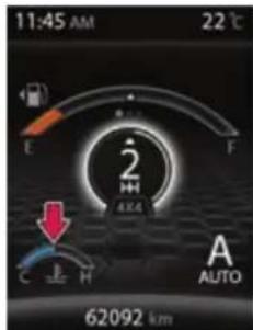
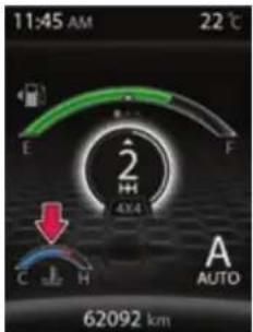
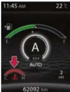
Torque On Demand (TOD).....130
Cruise Control....131
7 Driver Assist
Rain & Light Sensor....133
Reverse Park Assist....135
Audio Setting....141
8 Drive Modes
Drive Modes....144
Control Switches....144
Drive Mode Functionality......145
Drive Control System Display....149
Mood Lighting Display....151
CONTENTS
| 9 | Ambient Mood Lights |
| Mood Light Screen | 154 |
| Activation of Mood Lighting | 155 |
| Selecting Colour | 157 |
| Selecting Area | 157 |
| Switching off Mood Lighting | 158 |
| Mood Lights- Entry/Exit | 158 |
| 10 | Emergency & Breakdown Assistance |
| Emergency Equipment......160 | |
| Tool Kit......161 | |
| Hazard Warning Switch......161 | |
| Inertia Switch......162 | |
| In Case of Flat Tyre......163 | |
| Jump Lead Starting......167 | |
| Towing......169 | |
| Fuses......171 | |
| Bulb Specification......173 | |
| 24x7 Road Assistance......179 | |
| 11 | Maintenance |
| Maintenance & Service......184 | |
| Engine Compartment......185 | |
| Engine Oil......186 | |
| Brake Fluid Level......187 | |
| Engine Coolant Level......187 | |
| Power Steering Fluid Level......188 | |
| Windshield Washer Fluid Level.188 | |
| Battery......189 | |
| Turbocharger......189 | |
| Intercooler......190 | |
| Catalytic Converter......190 | |
| Tyres......191 | |
CONTENTS
11 Maintenance
Key Battery Replacement.....195
On Board Diagnostic (OBD).....196
Service Instructions....197
Service Schedule....198
12 Technical Information
Fuel Specification......210
Lubricant Specification......211
Technical Specification......214
Vehicle Dimensions.....217
13 Vehicle Care and Value Added Services
Vehicle Care....220
Washing....220
Waxing....221
Polishing....221
Interior Fabric Cleaning.....221
Paint Care....221
Wiper Care....222
Extended warranty....223
Value Added Services......225
CONTENTS
| 14 | Warranty – Terms and Conditions |
| 15 | Environment Safety |
| 16 | Vehicle Service and Service Coupon |
SAFETY
01
SAFETY
Safe Driving
Safety consciousness not only ensures your safety and the safety of other road users, but it also helps to reduce the wear and tear on your vehicle.
Safe driving depends on:
- How quickly you make decisions to avoid an accident.
- Your ability to concentrate.
- How well you can see and judge objects.
- How well familiar you are with your vehicle controls and its capabilities.
NOTE
Fatigue is a result of physical or mental exertion that impairs judgment. Driver fatigue may be due to inadequate sleep, extended work hours, strenuous work or combination of other factors. Take rest at regular intervals.
Safety tips
- Always take into account the road, weather conditions, vehicle distance in order to prevent accidents.
- Turn 'ON' the side indicators at least 30 meters before taking a turn or changing the lane.
- Decelerate to a safe speed before taking turn. Avoid braking during cornering.
- When overtaking other vehicles, watch out for the oncoming vehicle.
- Never drive under the influence of alcohol or drugs.
WARNING

Drinking and driving and/or taking drugs and driving are very dangerous combinations. Even a small amount of alcohol or drugs can affect your reflexes, perceptions and judgment. The possibility of a serious or even fatal accident is greatly increased when you drink or take drugs and drive.
Do not drink or take drugs and drive or allow anyone to drive who has been drinking or taking drugs.
- If your vehicle is equipped with infotainment/navigation system, set and make changes to your travel route only when the vehicle is parked.
- Program radio presets with the vehicle parked, and use your programmed presets to make radio use quicker and simpler.
Driving through water
Do not drive through flooded areas. Judge the depth of water before driving through it. Otherwise, water may enter the vehicle interior or the engine compartment.
If at all the situation demands that you have to drive through water then;
- Keep engine in higher RPM and crawl the vehicle in low gear.
- Flowing or rushing water creates strong forces. Driving through flowing water could cause the vehicle to be
carried away. Be very cautious about trying to drive through flowing water.
- Lightly apply the brake pedal to dry the liners until the brakes work effectively once you are out of water.
WARNING

Do not attempt to start the engine if vehicle gets flooded due to water. Tow the vehicle to a safe place. Contact a nearest TATA MOTORS authorised service center.
Driving on a rainy day
- Check wiper blades, lights and brakes for proper functioning and condition.
- Check the tyre treads depth, the condition of the tread and tyre.
- Avoid harsh braking and sharp turns. It may cause loss of control and lead to a skid.
- For slowing down, shift to lower gears and brake gently.
- Keep lights 'ON' if visibility is poor.
NOTE
If you have driven for a long time in heavy rain without braking, there may be a delayed response from the brakes when braking for the first time. You have to depress the brake pedal more firmly and repeatedly. Maintain a greater distance from the vehicle in front.
Driving through wet roads
On wet road or during light showers, “Aquaplaning” can occur. “Aquaplaning” is the loss of direct contact between the road surface and the vehicle’s tyres due to formation of a water film between them. Steering or braking the vehicle can be very difficult, and loss of control can occur.
NOTE
There is no hard and fast rule about aquaplaning. The best advice is to slow down when the road is wet.
Night driving
- Ensure that all lights are working and windshield, window glasses are clean.
- Select 'Antiglare' mode on IRVM.
- Drive more slowly at night than in the daytime, as the visual range is restricted at night. Maintain a speed such that you can stop within illuminated distance of head lamps.
- Do not use the high beam unless inevitable. It may dazzle the driver of the oncoming vehicle, thus causing an accident.
- Use head lamp main/dip beam to alert other road users on turns/ cross roads etc.
- Use side indicators well in advance for lane change or turning.
- Do not try to overtake other vehicles at night.
SAFETY
Driving on gradients
When climbing gradient, the vehicle may begin to slow down and show a lack of power. If this happens, shift to a lower gear and apply power smoothly so that there is no loss of traction.
When driving down a hill, the engine braking should be used by shifting to a lower gear.
Do not drive in neutral gear or switch off the engine.
NOTE
For more details refer 'Hill Hold Control (HHC) and 'Hill Descent Control' (HDC) in 'DRIVER ASSIST' section.
WARNING

On long and steep gradients, you must reduce the load on the brakes by shifting early to a lower gear. This allows you to take advantage of the engine braking effect and helps avoid overheating of brakes resulting in reduced braking efficiency.
Driving on highway
Stopping distance progressively increases with vehicle speed. Maintain a sufficient distance between your vehicle and the vehicle ahead.
For long distance driving, perform safety checks before starting a trip and take rest at certain intervals to prevent fatigue.
Use ‘Cruise Control’ (if equipped) if road and traffic conditions make it appropriate to maintain a steady speed for a prolonged period.
Occupant Safety
The restraint system can reduce the risk of vehicle occupants coming into contact with parts of the vehicle's interior in the event of an accident. The restraint system can also reduce the forces to which vehicle occupants are subjected during an accident.
The restraint system comprises:
- Seat belt system
- Air bags
The components of the restraint system work in conjunction with each other.
An air bag supplements a correctly worn seat belt. As an additional safety device, the air bag increases the level of protection for vehicle occupants in the event of an accident.
Seat belts and air bags do not protect against objects penetrating the vehicle from the outside.
WARNING

Modifications to the restraint system may cause it to no longer work as intended. The restraint system may then not perform its intended protective function and may fail in an accident or trigger unexpectedly.
This poses an increased risk of injury or even fatal injury.
Never modify parts of the restraint system. Never tamper with the wiring, the electronic components or their software.
Seat Belts
Seat belts are the most effective means of restricting the movement of vehicle occupants in the event of an accident or the vehicle rolling over. This reduces the risk of vehicle occupants coming into contact with parts of the vehicle interior or being ejected from the vehicle. Furthermore, the seat belt helps to keep the vehicle occupant in the best position in relation to the air bag.
The seat belt system comprises:
- Seat belts
- Retractor Pre - Tensioner Load Limiter (RPLL) for the front seat belts
If the seat belt is pulled out of the belt outlet quickly or with a jerky movement, the belt retractor locks. The belt strap cannot be extracted any further.
The RPLL tightens the seat belt in an accident, pulling the belt close against the body. However, it does not pull the vehicle occupant back in the direction of the backrest.
The RPLL does not compensate an incorrect seat position or the routing of an incorrectly fastened seat belt.
The use of seat belts and child restraint systems is required by law.
WARNING

If the seat belt is incorrectly fastened, it cannot protect as intended. Furthermore, an incorrectly fastened seat belt can cause additional injury. This poses an increased risk of injury or even fatal injury.
Make sure that all vehicle occupants are seated properly with a correctly fastened seat belt.
SAFETY
WARNING

The seat belt does not offer the intended level of protection if you have not moved the backrest to an almost upright position. When braking or in the event of an accident, you could slide underneath the seat belt and sustain abdomen or neck injuries. This poses an increased risk of injury or even fatal injury.
Adjust the seat properly before beginning your journey. Always ensure that the backrest is in an almost upright position and that the shoulder section of your seat belt is routed across the center of your shoulder.
WARNING

The seat belts may not perform their intended protective function if:
• they are damaged, modified, bleach or dyed
• the seat belt buckle is damaged
- the RPLL, belt anchorages or inertia reels have been modified Seat belts may sustain non-visible damage in an accident. Modified or damaged seat belts may tear or fail, e.g. in an accident. Modified RPLL could accidentally trigger or fail to deploy when necessary. This poses an increased risk of injury or even fatal injury.
Never modify the seat belts, RPLL, belt anchorages or inertia reels. Make sure that the seat belts are undamaged, not worn out and clean. Following an accident, have the seat belts checked immediately at a TATA MOTORS Authorized Service Centre.
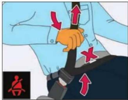
Proper use of the seat belts
All vehicle occupants must be wearing the seat belt correctly before beginning the journey. Also make sure that all vehicle occupants are always wearing the seat belt correctly while the vehicle is in motion.
When fastening the seat belt, always make sure that:
- the seat belt tongue is only inserted to the belt buckle belonging to that seat.
- the seat belt is tight across your body. Avoid wearing bulky clothing, e.g. a winter coat.
• the seat belt is not twisted. - the shoulder section of the belt is always routed across the center of your shoulder. The shoulder section of the belt must not come into contact with your neck or be routed under your arm. Where possible, adjust the seat belt to the appropriate height.
- the lap belt passes tightly and as low down as possible across your lap. The lap belt must always be routed across your hip joints and not across your abdomen. This applies particularly to pregnant women. If necessary, push the lap belt down to your hip joint and pull it tight using the shoulder section of the belt.
- the seat belt is not routed across sharp, pointed or fragile objects. e.g. pens, keys or eyeglasses. Store these in a suitable place.
- only one person is using a seat belt at a time.
SAFETY
- infants and children must never travel sitting on the lap of a vehicle occupant. In the event of an accident, they could be crushed between the vehicle occupant and seat belt.
- there are never objects between a person and the seat, e.g. cushions.
Seat belts are only intended to secure and restrain vehicle individual occupants.
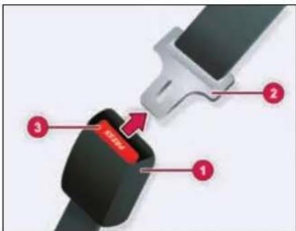
Seat belt adjustments
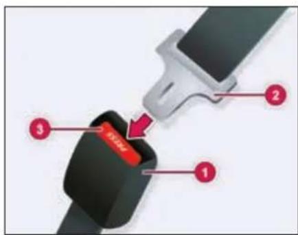
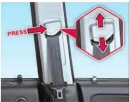
- Buckle 2. Tongue 3. Press Button
➢ Pull the belt tongue across your body and insert it into the buckle until click sound is heard.
➢ Check and ensure that the belt is not twisted.
➢ Position the lap portion of the belt as low as possible across your hip bone.
➢ Pull up the shoulder part of the belt to remove the slack. Make sure that the belt goes over your collar bones and across chest.
The lap portion of the belt should be worn across the pelvis, not across the waist.
To unlatch the belt, press the red button on the buckle. Guide the belt to the pillar as it retracts.
Make sure that the seat belt is fully rolled up. Otherwise, the seat belt or belt tongue will be trapped in the door or in the seat mechanism. This could damage the door, the door trim panel and the seat belt. Damaged seat belts can no longer fulfill their protective function and must be replaced. Visit a TATA MOTORS Authorized Service Centre.
SAFETY
Seat belt height adjustment
Adjust the height of seat belt shoulder section according to your comfort.
Lap belt
Pull the lap belt tongue and engage it into the belt buckle. Adjust the belt length. To lengthen the belt, hold the tongue at a right angle to the webbing and pull. To shorten, pull the loose end of the webbing. To unfasten, press the release button in the buckle.
WARNING

Position the lap belt as low as possible on your hip bone and not across the abdomen. If the lap belt is positioned across your abdomen, it could cause serious injuries in a crash.
Pregnant woman
Pregnant women should also always use a lap-shoulder belt. The lap belt portion should be positioned as low as possible on the hip bones to avoid any possible pressure on the abdomen.
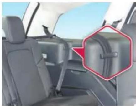
Seat belt hanger (if equipped)
natural_image
Interior view of a car showing rear seats and seatbelt, with a red hexagonal annotation highlighting the side panel (no text or symbols present)When second or third row seat is not occupied, hook the seat belts at its respective belt hanger to avoid rattling. Make sure the belt webbing is not twisted.
Child Safety
Important safety notes
Accident statistics show that children secured in the rear seats are safer than children secured in the front-passenger seat. For this reason, TATA MOTORS strongly advises that you install a child restraint system on a rear seat. Children are generally better protected there.
WARNING

If you leave children unsupervised in the vehicle, they could set it in motion by, for example:
- release the parking brake.
- shift the automatic transmission out of the parking position P.
- start the engine.
In addition, they may operate vehicle equipment and become trapped. There is a risk of an accident and injury.
When leaving the vehicle, always take the Key with you and lock the vehicle. Never leave children unsupervised in the vehicle.
WARNING

If persons, particularly children are subjected to prolonged exposure to extreme heat or cold, there is a risk of injury, possibly even fatal. Never leave children unattended in the vehicle.
WARNING

If the child restraint system is subjected to direct sunlight, parts may get very hot. Children may burn themselves on these parts, particularly on the metal parts of the child restraint system. There is a risk of injury.
If you leave the vehicle, taking the child with you, always ensure that the child restraint system is not exposed to direct sunlight. Protect it with a blanket, for example. If the child restraint system has been exposed to direct sunlight, let it cool down before securing the child in it. Never leave children unattended in the vehicle.
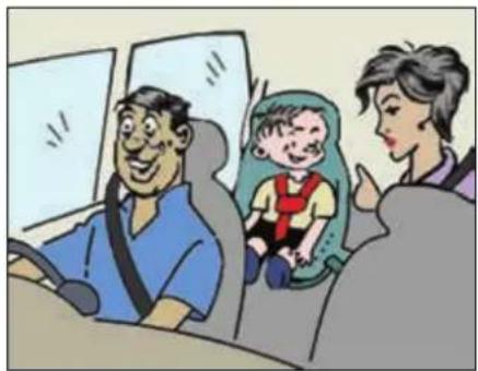
Child Restraint System (CRS)
TATA MOTORS strongly recommends the use of Child Restraint Systems (CRS) for all children up to age of 12 years.
WARNING

If the child restraint system is installed incorrectly or is not secured, it can come loose in the event of an accident, heavy braking or a sudden change in direction. The child restraint system could be thrown about, striking vehicle occupants. There is an increased risk of injury, possibly even fatal.
Make sure that you observe the child restraint system manufacturer's installations and the notes on use. Please ensure, that the base of the child restraint system is always resting completely on the seat cushion. Never place objects, e.g. cushions, under or behind the child restraint system. Only use child restraint systems with the original cover designed for them. Only replace damaged covers with genuine covers.
SAFETY
WARNING

Child restraint systems or their securing systems which have been damaged or subjected to a load in an accident can no longer protect as intended. The child cannot then be restrained in the event of an accident, heavy braking or sudden changes of direction. There is an increased risk of injury, possibly even fatal.
Replace child restraint systems which have been damaged or subjected to a load in an accident as soon as possible.
Selection and installation of CRS
Always select the child restraint system (CRS) that complies with latest safety standards (AIS072/ECE R44). They are classified according to the child's size, height and weight. Select the appropriate CRS for your child. Ensure that the child fits properly in the CRS and CRS is securely installed in the vehicle. Make sure that you observe the child restraint system manufacturer's manual in detail for installation procedure.
natural_image
Cartoon illustration of a family inside a car, including a man seated in a seat, a woman in a green seat, and a child in a red vest (no text or symbols visible)Recommended CRS position
The suitability of seat position for carriage of children and recommended category of child restraint system is shown in the table below.
| Group | Mass Group | Age Group | Front Passen- ger | 2^nd Row Outboard LH | 2^nd Row Outboard RH | 2^nd Row Center | 3^rd Row Outboard LH | 3^rd Row Outboard RH |
| 0 | Up to 10 kg | Up to 9 months | X | X | U | X | X | X |
| 0+ | Up to 13 kg | Up to 24 months | X | X | U | X | X | X |
| I | 9 to 18 kg | 9 months to 48 months | X | X | U | X | UF | UF |
| II | 15 to 25 kg | Approx. 3 to 7 years | X | X | U | X | UF | UF |
| III | 22 to 36 kg | Approx. 6 to 12 years | X | X | U | X | UF | UF |
X - Seat Position not suitable for children in this age group.
U - Suitable for 'Universal*' category restraints approved for use in this age group.
UF - Suitable for forward facing ‘universal’ category restraints approved for use in this age group.
*Universal is a category in the AIS072 / ECE R44 norm.
SAFETY
NOTE
Accident statistics show that children secured in the rear seats are safer than children secured in the front-passenger seat. For this reason, TATA MOTORS strongly advises that you install the child restraint system on a rear seat.
When installing child restraint system in rear seat, push the front seat fully forward so that child's feet do not touch the front seat back.
Storage for CRS
Secure child restraint system safely in the vehicle or stow it in the luggage compartment if not being used.
While the vehicle is in motion an unrestrained child restraint system could flung through the vehicle interior in the event of a sudden braking, maneuver or an accident. This could cause injuries to the travelling occupants.
Check list
- Never carry children on somebody's lap when vehicle is in motion.
- Always secure children in the vehicle in a CRS. The CRS must be suitable for the child's height, weight and build.
- Observe the instructions from the manufacturer of the CRS and always keep the instruction manual in the vehicle.
- Always make sure that the seat belt routing is correct for children and they are sitting in the correct position.
- Do not leave any toys or other objects loose in the CRS or on the seat while the vehicle is in motion.
WARNING

Each CRS should be used for one child only.
Child Lock
WARNING

If children are traveling in the vehicle, they could:
- open doors, thus endangering other people or road users
- exit the vehicle and be caught by oncoming traffic
• operate vehicle equipment and become trapped
There is a risk of an accident and injury.
Always activate the child-proof locks provided on rear door and window inhibit switch if children are traveling in the vehicle. When leaving the vehicle, always take the key with you and lock the vehicle. Never leave children unattended in the vehicle.
Child lock
You secure each door individually with the child lock on the rear doors. A door secured with a child lock cannot be opened from inside the vehicle. When the vehicle is unlocked, the door can be opened from the outside.
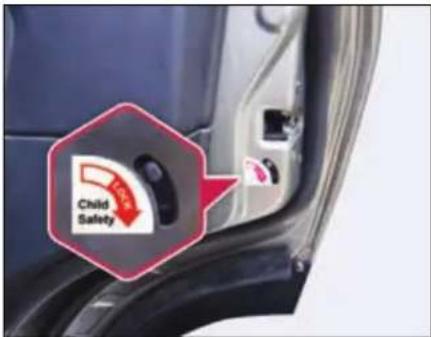
To activate: press the child lock lever down in the direction of arrow.
Make sure that the child lock is working properly.
To deactivate: pull the child lock lever up in the direction of arrow.
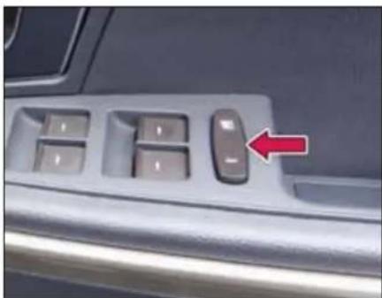
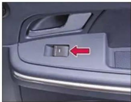
Window Inhibit Switch
Press and activate the inhibit switch, so individual window winding switches provided on rear doors cannot be operated. Refer "Opening and Closing" section for more details.
natural_image
Close-up of a car interior control panel with a red arrow pointing to the left side (no text or symbols visible)WARNING

If children operate the windows they could be get trapped, particularly if they are left unsupervised. There is a risk of injury.
Activate the window inhibit feature when children are travelling. When leaving the vehicle, always take the
key with you and lock the vehicle. Never leave children unsupervised in the vehicle.
Pets in the vehicle
WARNING

If you leave animals unattended or unsecured in the vehicle, they could press buttons or switches.
As a result, they could:
- activate vehicle equipment and become trapped.
- activate or deactivate systems, thereby endangering other road users
Unsecured animals could also be flung around the vehicle in the event of an accident or sudden steering or braking, thereby injuring vehicle occupants. There is a risk of an accident and injury.
Never leave animals unattended in the vehicle. Always secure animals properly during the journey, e.g. use a suitable animal transport box.
SAFETY
Air Bags - Supplemental Restraint System
The installation point of an air bag can be recognized by the AIR BAG symbol.
An air bag complements the correctly fastened seat belt. It is no substitute for the seat belt. The air bag provides additional protection in applicable accident situations.
Not all air bags are deployed in an accident. The different air bag systems function independently from one another
Important safety notes
WARNING

If you do not sit in the correct seat position, the air bag cannot protect as intended and could even cause additional injury when deployed. This poses an increased risk of injury or even fatal injury.
To avoid hazardous situations, always make sure that all of the vehicle's occupants:
• have fastened their seat belts correctly, including pregnant women
- are sitting correctly and maintain the greatest possible distance to the air bags
- are placed no objects between the air bag and the vehicle's occupants.
- Adjust the seats properly before beginning your journey. Always make sure that the seat is in an almost upright position.
- Move the driver's and front-passenger seats as far back as possible. The driver's seat position must allow the vehicle to be driven safely.
- Only hold the steering wheel on the outside. This allows the air bag to be fully deployed.
- Always lean against the backrest while driving. Do not lean forwards or lean against the door or side window. You may otherwise be in the deployment area of the air bags.
- Always keep your feet in the footwell in front of the seat. Do not put your feet on the dashboard, for example. Your feet may otherwise be in the deployment area of the air bag.
Objects in the vehicle interior may prevent an air bag from functioning correctly.
Before starting your journey and to avoid risks resulting from the speed of the air bag as it deploys, make sure that:
- there are no people, animals or objects between the vehicle occupants and an air bag.
- there are no objects between the seat, door and B-pillar.
- no hard objects, e.g. coat hangers, hang on the grab handles or coat hooks.
- no accessories, such as cup holders, are attached to the vehicle within the deployment area of an air bag, e.g. to doors, side windows, rear side trim or side walls.
- no heavy, sharp-edged or fragile objects are in the pockets of your clothing. Store such objects in a suitable place.
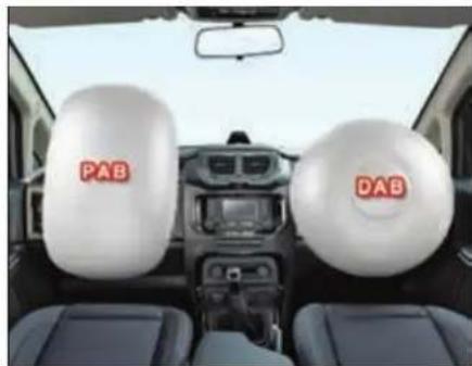
Front Air bags
natural_image
Interior view of a car showing two white head coverings labeled 'PAB' and 'DAB', with no visible text or symbols beyond the labels.Driver's air bag (DAB) deploys in front of the steering wheel. Front-passenger air bag (PAB) deploys in front of and above the glove box.
When deployed, the front air bags offer additional head and thorax protection for the occupants in the front seats.
The PASSENGER AIR BAG OFF and PASSENGER AIR BAG ON indicator lamps inform you about the status of the front passenger air bag.
Passenger Air Bag (PAB) switch
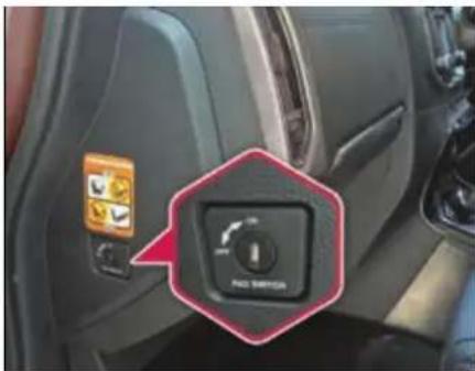
If it becomes necessary to fit a child restraint on the front passenger seat the passenger airbag must be de-activated using the switch located on the left side of the dashboard. This switch can be accessed once front passenger side door is opened.
On the contrary, when an adult is seated in the front passenger seat, ensure that PAB disabling switch is turned to 'ON' position. This will ensure that the passenger airbag is operational in the event of a collision. This switch is operated using the ignition/remote key blade.
SAFETY
Passenger Air Bag (PAB) indicator lamp
The indicator lamps display the status of the front-passenger front air bag.
- Passenger air bag OFF lights up:

the front-passenger front air bag is deactivated. It will then not be deployed in the event of an accident.
- Passenger air bag ON lights up: the front-passenger front air bag is enabled. If, in the event of an accident, all deployment criteria are met, the front-passenger front air bag is deployed.
Side Air bags
WARNING

Unsuitable seat covers could restrict or even prevent the deployment of the air bags integrated into the seats. Consequently, the air bags cannot protect vehicle occupants as they are designed to do. This poses an increased risk of injury or even fatal injury.
You should only use seat covers that have been approved for the respective seat by TATA MOTORS.
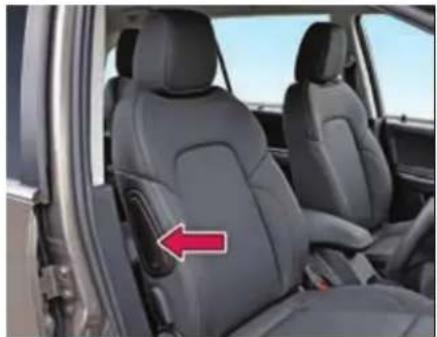
natural_image
Interior view of a car showing the rear seat of a vehicle with a red arrow pointing to the side panel (no text or symbols visible)Front side impact air bags deploy next to the outer bolster of the seat backrest.
When deployed, the side impact air bag offers additional thorax protection. It also offers additional pelvis protection for occupants in the front seats.
However, it does not protect the:
- head
- neck
- arms
In the event of a side impact, the side impact air bag is deployed on the side on which the impact occurs.
If the belt tongue is engaged in the belt buckle, the side impact air bag on the front passenger side deploys if an appropriate accident situation occurs. In this case, deployment is independent of whether the front passenger seat is occupied or not.
Curtain air bags
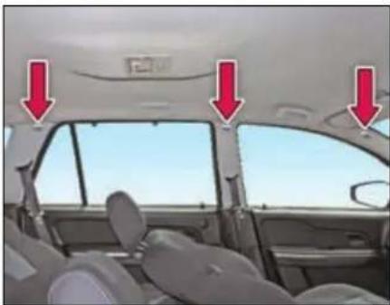
natural_image
Interior view of a car showing the dashboard and side seats with red arrows pointing to the rear window (no text or symbols visible)Curtain air bags are integrated into the side of the roof frame and deployed in the area from the 1 ^st row seat to the 3 ^rd row seat.
When deployed, the curtain air bag enhances the level of protection for the head.
However, it does not protect the chest or arms.
In the event of a side impact, the curtain air bag is deployed on the side on which the impact occurs.
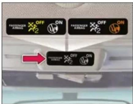
Airbag warning label
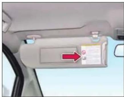
natural_image
Interior view of a car showing the rearview mirror with a red arrow pointing to the side panel (no text or symbols visible)Airbag warning information is provided on the front passenger's sun visors.
NOTE
If the Air bag warning tell-tale

on the instrument cluster stays ON while driving, there may be a problem with the Air bag system. Contact TATA MOTORS Authorised Service Centre.
In case of any frontal damage to your vehicle or any maintenance required to be performed should be done by TATA MOTORS Authorised Service Centre only.
Do not permit anyone else to do any service, inspection, maintenance or repair on any SRS components or wiring.
Improper work on the SRS system will result in inadvertent deployment of the air bag or malfunctioning.
SAFETY
ABS (Anti-lock Braking System)
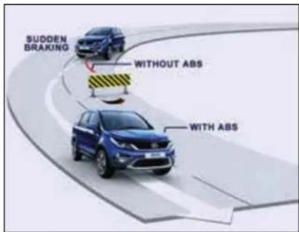
ABS regulates brake pressure in such a way that the wheels do not lock when you brake.
This allows you to continue steering the vehicle when braking.
The AB learning lamp in the instrument cluster lights up when the ignition is switched on. It goes out when the engine is running.
WARNING

If ABS is faulty, the wheels could lock when braking. The steerability and braking characteristics may be severely impaired. There is an increased danger of skidding and accidents.
Drive on carefully. Have ABS checked immediately at a TATA MOTORS Authorized Service Centre as soon as possible.
When Braking:
If ABS intervenes: continue to depress the brake pedal vigorously until the braking situation is over.
To make a full brake application: depress the brake pedal with full force.
If ABS intervenes when braking, you will feel a pulsing in the brake pedal. The pulsating brake pedal can be an indication of hazardous road conditions, and functions as a reminder to take extra care while driving.
WARNING

The stopping distance required for vehicles with ABS may be slightly more than conventional brake system but ABS will still offer the advantage of helping you maintain directional control.
However, remember that ABS will not compensate for bad road or weather conditions or poor driver judgment. Drive within safety margins, taking into consideration prevailing weather and traffic conditions.
EBD (Electronic Brake-force Distribution)
EBD monitors and controls the brake pressure on the rear wheels to improve driving stability while braking.
EBD provides optimal braking pressure distribution between front and rear axle to optimize braking distance and to ensure vehicle stability by means of lowering braking pressure increase at rear axle.
WARNING

If EBD Ⓔ malfunctioning, the rear wheels can lock, e.g. under full braking. This increases the risk of skidding and an accident.
You should therefore adapt your driving style to the different handling characteristics. Have the brake system checked immediately at a TATA MOTORS Authorized Service Centre as soon as possible.
E-Key
An E-Key is an electronic access and authorization system which is provided as a standard feature on your vehicle.
Unlocking principle
The transponder which is built into the ignition E-Key carries a unique identification code. The vehicle unlocks when the code on the E-Key matches with the code on the Engine Management System (EMS).
Engine starting
When the key is inserted and the ignition is switched 'ON', all codes are communicated within concerned components (E-Key, Immobilizer and EMS). The engine will start only if all the codes match.
NOTE
Key can be removed from the ignition switch only when the vehicle is in Park (P) mode (applicable for AT variants).
Loss of keys
If one of the keys is lost, contact your nearest TATA MOTORS authorised dealer immediately.
WARNING

- Do not turn 'ON' ignition switch by using E-key with any type of metal wound around its grip or in contact with it. This may be detected as abnormal condition by immobilizer and prevent engine from starting.
- Do not leave the E-key in areas of high temperature. The transponder in it will behave abnormally when reused.
- Do not try to start the vehicle when the Immobilizer indicator lamp on the instrument cluster is glowing. In this condition the vehicle will not start and the vehicle's battery will also be drained due to frequent cranking.
SAFETY
Immobilizer - Anti-Theft Device
Immobilizer system is designed to prevent vehicle theft by electronically disabling the engine ignition system. The engine can be started only with vehicle's original Immobilizer ignition key which has an electronic identification programmed code.
NOTE
Use only E-key, the other should be kept in a safe location. Note down 'key Tag no.' information (and keep it safe) which is required while getting new/spare keys.
Remember that it is not possible to prepare new/spare keys without the "key Tag number." Take precaution about E-key, as without E-key vehicle cannot be started.
| Vehicle Condition | Immobilizer Lamp Status | Vehicle State | Meaning / Function of the state |
| Ignition OFF | Blinking | Locked | Vehicle Immobilized and awaiting electronic key |
| Ignition ON | OFF | Unlocked | Normal condition and ready to start the vehicle |
| Ignition ON | ON | Locked | - Problem with key (Wrong key used to start vehicle)- Problem with Immobilizer system. Contact a TATA MOTORS authorized service centre |
| Ignition ON | Blinking | Unlocked | Contact a TATA MOTORS authorized service centre immediately |
OPENING AND CLOSING
02
OPENING AND CLOSING
Key
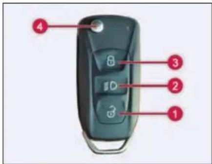
-
Unlock
-
Approach Light
-
Lock
-
Key blade in/out button
Unlocking
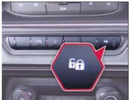
Pressing unlock button (1) will unlock the doors and fuel flap. Using settings provided in Infotainment system, single stage (All doors unlock) and dual stage (driver door at first press and remaining door at second press) unlocking can be done.
Approach light
Press approach light button (2) once, low beam, park and roof lamp will turn 'ON' for approx. 60 seconds. This feature helps to find and reach the vehicle or reach home in dark and cloudy condition. To switch 'OFF' the approach lights, press and release the same button or it automatically turns 'OFF' after 60 seconds approx.
Approach light ON time can be adjusted using settings provided in Infotainment system.
Locking all doors
To lock all doors, press Lock button (3) once. Locking will be confirmed by two flashes of turn indicators.
If lock button is pressed on the remote key with the driver door open, locking-un-locking takes place with audible warning sound.
While if any other door is open, the vehicle gets locked but indicators do not flash.
Folding key blade in / out
Press button (4) to flip out the key blade. For folding, press the button (4) and fold the key blade inside.
NOTE
Key Blade should not be folded without pressing the button. Also, it should not be forced in any direction apart from folding direction to avoid damage to Flip Mechanism.
Always keep the key blade in folded condition when not in use.
For AT variants, In certain conditions key blade surface temperature will be higher which is normal.
Remote key features
Vehicle search
In vehicle lock condition if lock button on remote key is pressed the turn indicators of vehicle flashes 4 times.
NOTE
For AT variants, key can be removed from the ignition switch only when the vehicle is in Park (P) mode.
Key rotation from Ignition ON to key LOCK position to be done slowly to avoid obstruction feel.
If any difficulty in removal in Park (P) mode, Contact nearest TATA MOTORS authorized service centre.
Automatic activation of immobilizer
When key is removed from ignition switch, the engine will be immobilized automatically even if you forget to lock the vehicle.
Theft detection
When the vehicle is locked with the remote key and if any of the door or ignition switch is tried to be accessed with any
other key, theft detection alarm gets activated. Press either the 'Lock' or 'Unlock' button to deactivate the alarm.
Auto locking / unlocking of doors / auto relock
Vehicle doors get automatically locked when all doors are closed and the vehicle speed crosses approx. 10 kmph.
When ignition key is taken out all the doors get automatically unlocked.
Also, when unlocked with remote key and if no door is opened within approx. 30 seconds, vehicle doors get automatically locked.
Anti-grab / anti-scan coding
The remote control set of this security system is protected against the use of devices called 'scanners' and 'grabbers' which can record and reproduce some types of remote codes.
Force panic alarm
Press the 'Lock' and 'Unlock' button simultaneously to activate panic alarm. Press either the 'Lock' or 'Unlock' button to deactivate panic alarm.
Sleep Mode
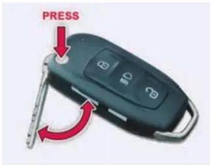
If remote key is not used for more than a week then its functionalities will turn to sleep mode. In such a case, to activate the remote key functionalities, open the door mechanically with the key blade once.
OPENING AND CLOSING
Do's and Don'ts for using remote key
| DO'S | DONT'S | |
| 1 | Do always keep your vehicle's battery properly charged. | Don't play with Lock/Unlock push-button of remote while in the vicinity of your vehicle, as it could lead to an unintentional un-locking your vehicle. |
| 2 | Do always press the Lock push-button of the remote only after coming out from the vehicle. | Don't lock the vehicle by remote while sitting inside the vehicle. |
| 3 | Do keep the remote in safe and secure place. | Don't use discharged batteries in remote, as it could damage the remote. |
| 4 | In case of any problem, always contact TATA MOTORS authorized service outlet. | Don't remove the battery connection of the vehicle while the vehicle has been locked by remote. First unlock the vehicle by remote, and then remove the battery connection. |
Important
Don't operate Unlock button of remote key while in the vicinity of your vehicle, as it could lead to an unintentional unlocking your vehicle.
If red LED remote flashes for 5 times after pressing any button on remote key, it indicates that key battery is discharged. It is recommended to replace battery at a TATA MOTORS Authorized Service Centre.
Don't use discharged batteries in remote, as it could damage the remote.
Refer 'Maintenance' section for battery replacement.
Don't remove the battery connection of the vehicle while the vehicle has been locked by remote.
Doors
Doors can be unlocked/locked using one of the following options
- By remote key
- By taking out key from IGN lock
- By pressing lock/unlock switch on fascia switch bank
- By pulling popup knob on driver door
Doors can also be locked/unlocked using mechanical key.
Door locking / unlocking with mechanical key
Both front doors (driver and front passenger) has separate locking facility. Both doors can be locked or unlocked from outside using the mechanical key.
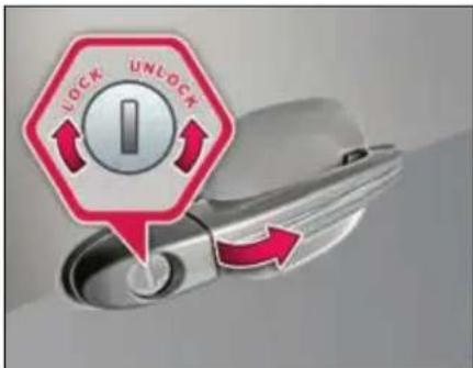
All doors can be locked / unlocked manually from outside using driver door key slot. Insert the mechanical key and turn it clockwise to lock and counter clockwise to open the doors.
OPENING AND CLOSING
Locking without a key from inside
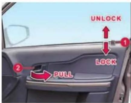
All the doors can also be locked from inside by pressing knob (1) on driver door and independently on other respective doors.
Opening the doors from inside
All doors can be opened from inside. To open, pull the door opening knob (1) and then lever (2).
WARNING

Do not operate knob of driver door when door is open.
NOTE
Single pull over-ride function is provided for driver door. In panic situation you can directly open driver door operating door lever. No need to operate pop-up knob.
Door Lock/Unlock switch
All doors can be locked and unlocked by the lock/unlock switch provided on the fascia switch bank.
Windows
Power windows
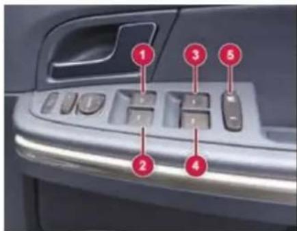
- Front Window Winding Switch (Right)
- Front Window Winding Switch (Left)
- Rear Window Winding Switch (Right)
- Rear Window Winding Switch (Left)
- Window Inhibit Switch
Glasses on all four windows of your vehicle can be operated by switches provided on the driver door. They work when the key is in the 'IGN ON' position.
NOTE
Power windows can also be operated for approx. 3 minutes in 'IGN OFF' position or after key is removed.
Do not use sun blinds when rear window glasses are open.
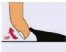
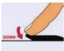
Express down (if equipped)
Window glasses can be opened by a single press of the switch. The downward movement of window glass can be stopped by pulling the switch to UP position when moving downwards.
Long press will activate the express down function.
Option 1: Provided on all doors (for XT)
Option 2: Provided on driver door (for other variants)
Individual switches
Individual window winding switches have been provided on the front passenger and rear doors.
Glasses are wound up by pulling the switch and are lowered by pressing.
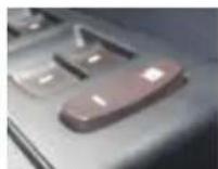
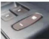
natural_image
Close-up of a car's side panel showing a black button with a red arrow pointing to the left side (no text or symbols visible)WARNING

While closing the window glass, body parts become trapped between the window glass and the door frame as the window glass moves. There is a risk of injury.
Window Inhibit Switch
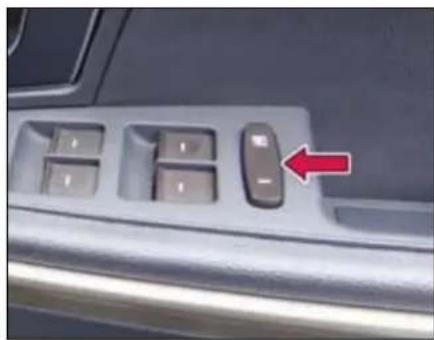
natural_image
Close-up of a car's front panel with four keys and a red arrow pointing to the left button (no text or symbols visible)Inhibit OFF (Released position)
When switch is re-leased, the individual switches provided on rear passenger door can be operated. It
can also be operated from the switches on driver's arm rest.
OPENING AND CLOSING
Inhibit ON (pressed position)
When this switch is pressed the individual switches provided on rear passenger doors cannot be operated. It
can only be operated by using the window switches on driver's arm rest.
WARNING

If children operate the windows they could be get trapped, particularly if they are left unsupervised. There is a risk of injury.
Activate the window inhibit feature when children are travelling. When leaving the vehicle, always take the key with you and lock the vehicle. Never leave children unsupervised in the vehicle.
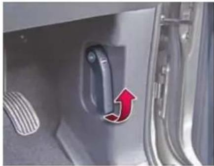
Bonnet
WARNING

Always switch off the windshield wipers and the ignition before opening the bonnet.
WARNING

Certain components in the engine compartment, such as the engine, radiator and parts of the exhaust system, can become very hot. Working in the engine compartment poses a risk of injury.
Opening
Make sure that the vehicle is in neutral gear with the parking brake applied.
NOTE
Make sure that the wiper arms are not raised before you lift up the bonnet to avoid damaging the wiper arms and the bonnet.
➢ Pull the engine bonnet release lever. The bonnet will pop up slightly.
natural_image
Close-up of a car door handle with a red arrow pointing to the left side (no text or symbols visible)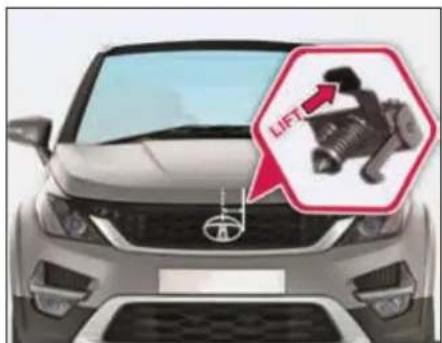
natural_image
Front view of a Toyota car with an inset showing a mechanical component labeled 'LIFT' (no text or symbols on the main body)➢ Raise the bonnet slightly and lift the secondary lock lever located under the bonnet center with your fingers.
➢ Lever is located slightly on right side from center of bonnet.
➢ Lift the bonnet up slowly. Hydraulic balancers hold the bonnet.
Closing
To close the bonnet, hold the bonnet and pull it down slowly.
➢ Lower the bonnet and let it fall from short height.
➢ Check that the bonnet latch has engaged properly. If the bonnet can be raised slightly, it is not properly engaged. Do not press the closed bonnet. Open the bonnet again and close it with a little more force.
WARNING

Make sure that the bonnet is properly latched before driving. It may open up when the vehicle is in motion and block your view. In this situation there is a risk of an accident.
Tail Gate
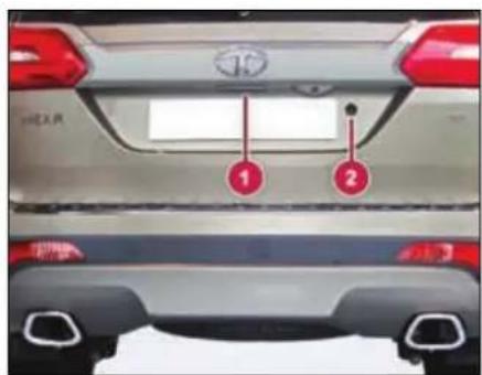
Opening
To open the tail gate, press the 'Unlock' button on the remote key. Once the vehicle is unlocked, pull the door handle (1) on the tail gate.
A separate lock (2) is also provided on the tailgate. It can be opened by using mechanical key.
Closing
Pull the tailgate down using handle. Allow the tailgate to drop into the lock.
For locking the tail gate, press the 'Lock' button on the remote key.
WARNING

Always make sure that the tail gate is closed and latched securely.
OPENING AND CLOSING
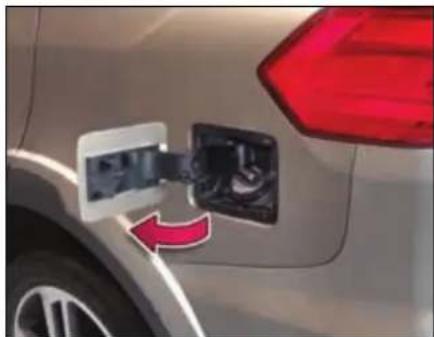
Fuel Lid
natural_image
Close-up of a car's side panel with a red arrow indicating fuel direction (no text or symbols visible)Opening
Fuel Lid can be unlocked using one of the following options.
- By remote key
- By taking out key from IGN lock
- By pressing lock/unlock switch on fascia switch bank
- By pulling popup knob on driver door
Unlock your vehicle and open the flap by gently pressing it. Turn the fuel filler cap counter clockwise and remove it.
NOTE
Remove the fuel filler cap slowly, and wait for any hissing to stop. The fuel may be under pressure and may spray out.
Closing
Gently push to lock the fuel flap back to its position. It gets locked once the vehicle is locked using the central locking.
WARNING

Fuel vapour is extremely hazardous. Always switch off the engine before refueling and never refill near sparks or open flames. Do not use cell phone while refueling.
Do not continue adding fuel after the automatic shut off function is operated, if equipped in fuel filling nozzle at the fuel station. Overfilling the fuel tank could damage the fuel system.
NOTE
If fuel cap needs replacement, ensure that it is replaced by a genuine cap at TATA MOTORS authorized service centre only.
Manual Fuel flap opening
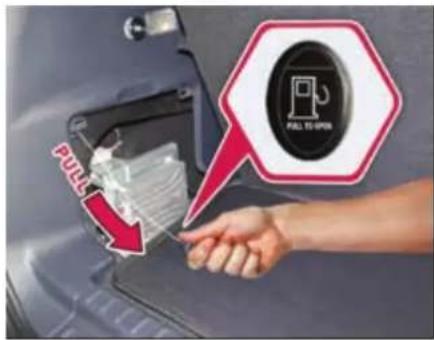
Alternatively, you can also open the fuel flap manually by following the below steps:
▶ Open the Tail Gate
➢ Open the Trim Cover fitted to the left hand side.
You will find a cable with a knob.
➢ Slightly pull this knob to open the fuel flap.
NOTE
The fuel flap opening cable should be used only in case of emergency/failure of central locking system/electrical system.
DASHBOARD & FEATURES
03
DASHBOARD AND FEATURES
Cockpit
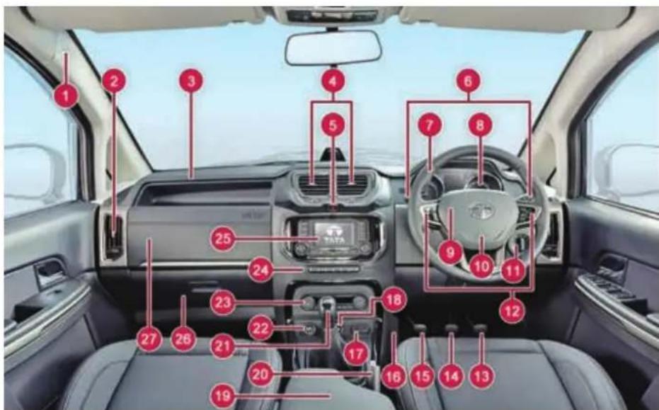
| 1 | Side Air bags - if equipped |
| 2 | A.C. Air vent (Side) |
| 3 | Air Bag (PAB) - if equipped |
| 4 | A.C. Air vent (Middle) |
| 5 | Hazard Warning Switch |
| 6 | Combi-Switch |
| 7 | Steering Wheel |
| 8 | Instrument Cluster |
| 9 | Horn Pad |
| 10 | Air Bag (DAB) |
| 11 | Master Light Switch |
| 12 | Steering Wheel Switches |
| 13 | Accelerator Pedal |
| 14 | Brake Pedal |
| 15 | Clutch Pedal – (Not in AT) |
| 16 | Foot Rest |
| 17 | USB/AUX Port |
| 18 | Drive Control Switch- if equipped |
| 19 | Arm Rest |
| 20 | Parking Brake Lever |
| 21 | Gear Shift Lever |
| 22 | Power Socket |
| 23 | Heating/Ventilation/AC Control panel |
| 24 | Fascia Switches |
| 25 | Infotainment System |
| 26 | Glove Box |
| 27 | Chiller Box |
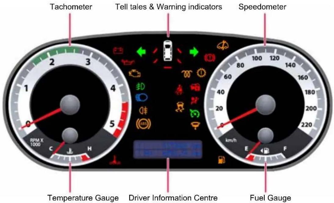
Instrument Cluster
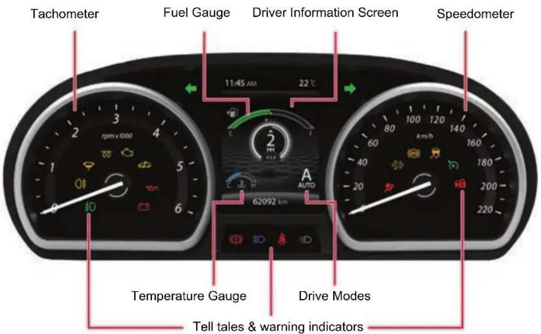
NOTE: All indicators shown may not be applicable to your vehicle.
DASHBOARD AND FEATURES
Welcome Strategy
At every key IN and ignition ON, the instrument cluster needles and gauges moves to MAX. and returns to 'O' position. This is a welcome strategy.
Speedometer
Speedometer indicates the actual vehicle speed in km/h.
NOTE
In vehicle running condition if the speedometer is not showing the vehicle speed, take your vehicle to TA-TA authorized service center
Tachometer
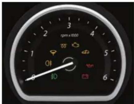
Tachometer indicates engine speed in revolutions per min (rpm).
WARNING

When engine is accelerated beyond safe 'rpm', the tachometer pointer turns RED. In such case, reduce the engine RPM immediately.
Never drive the vehicle beyond safe 'rpm'. This may cause severe engine damage.
Odometer
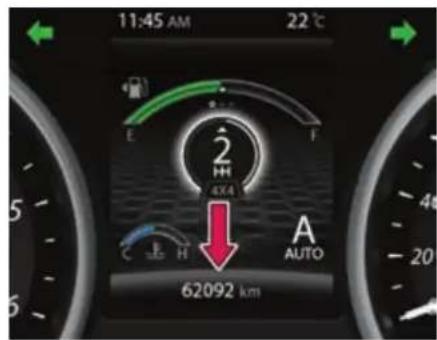
Odometer indicates total distance traveled by vehicle up to 999999 km with the resolution of 1 km.
The Odometer reading freezes when reach to maximum value.
Fuel Gauge
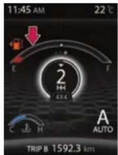
Very Low
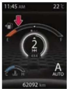
Low
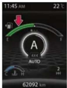
Half
When the ignition switch is in 'ON' position, fuel gauge gives an approximate indication of the amount of fuel in the fuel tank. 'F' stands for full and 'E' stands for empty.
Fuel gauge graphics color change from green to amber and then red, as the fuel quantity in fuel tank reduces.
Fuel gauge change to red and low fuel warning lamps on when fuel in the tank is near to empty position. This is a low fuel warning, refill immediately.
NOTE
Keep the ignition switch in ON position and check the fuel level when the vehicle is stationary and preferably on level road.
On inclines, curves, during braking and sudden acceleration due to the movement of fuel in the tank, the fuel level display may fluctuate or the low fuel warning lamp may illuminate earlier than usual.
WARNING

Do not continue adding fuel after the automatic shut OFF function (provided on fuel filling nozzle, if equipped) is operated.
Driving the fuel tank too low or empty can cause the engine to stall and could endanger the passengers. User must stop and obtain the additional fuel as soon as possible once low fuel warning comes ON or RED bar ON in the Fuel gauge.
Low fuel warning symbol will blink if there is any fault in the system. Take your vehicle to the nearest TATA MOTORS Authorized service station if the symbol starts blinking.
DASHBOARD AND FEATURES
Temperature Gauge
Normal
Above normal
High
The gauge indicates the temperature level of the engine coolant after ignition switch is in ON position
It indicates the coolant temperature in the form of a digital bar graph. Blue indicates normal temperature and red indicates high temperature. Temperature gauge graphics color changes from blue to red as the engine coolant temperature reaches to high temperature. When temperature is higher, engine coolant temperature warning lamp will turn red with a buzzer.
NOTE
RED color of temperature gauge along with warning lamp indicates high coolant temperature warning
lamp this indicates overheating that may damage the engine. Stop the engine, let the temperature of engine reduce and then take your vehicle to the nearest TATA MOTORS authorized service centre.
WARNING

Never remove the radiator pressure cap from the radiator when the engine is hot. Do not restart the engine until the problem has been duly attended.
Driver Information Screen
| Display Message | Description | Action by the User |
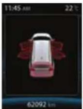 | All Door Open | |
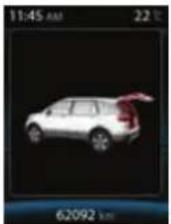 | Only Tailgate is open | This warning shall be minimised in the display if still the door opened after 5 sec and user can acknowledge the warning through by pressing the Trip switch.Note: In Engine or Vehicle running condition the warning shall be displayed in minimised screen |
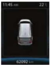 | All doors closedThis feature monitors the doors status to warn the driver if any door open (including driver door and tailgate) is detected. |
DASHBOARD AND FEATURES
| Display Message | Description | Action by the User |
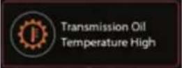 | This message displayed when transmission oil temperature is higher than allowable limit. | User has to take the vehicle to Authorized Tata motors service station. |
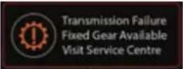
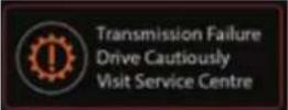 | This message displayed when transmission related failure is present. | User has to take the vehicle to Authorized Tata motors service station. |
 | This message displayed when transmission related failure is present. | User has to take the vehicle to Authorized Tata motors service station. |
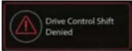
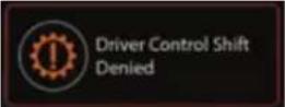 | This message displayed when gear shift is denied in manual mode. | User has to drive the vehicle in recommended speed to change the gear. |
 | Torque On Demand (TOD) System Fault | User has to take the vehicle to Authorized Tata motors service station. |
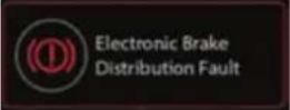 | Electronic Brake Distribution (EBD) System Fault | User has to take the vehicle to Authorized Tata motors service station. |
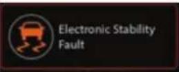 | Electronic Stability Program (ESP) System Fault | User has to take the vehicle to Authorized Tata motors service station |
 | This message comes ON when seat belt is not fastened. | User has to fasten the seat belt |
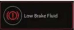 | This message comes ON when brake fluid level is low. | User has to take the vehicle to Authorized Tata motors service station |
 | This message comes ON when park brake is engaged | User has to dis engage the Park brake before start moving the vehicle |
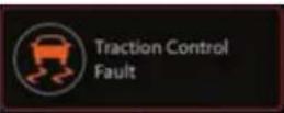 | Traction Control System Fault | User has to take the vehicle to Authorized Tata motors service station |
 | This message comes ON when Ice is possible on road due to low outside air temperature | User has to drive the vehicle carefully |
DASHBOARD AND FEATURES
| Display Message | Description | Action by the User |
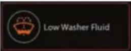 | This message comes ON when washer fluid level is low and it shall be displayed only in Ignition OFF- ON condition not in vehicle running condition (If applicable). | User has to fill the water in the fluid tank |
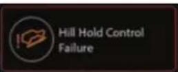 | Hill Hold Control (HHC) System Failure | User has to take the vehicle to Authorized Tata motors service station |
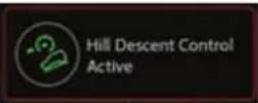 | Hill Descent Control (HDC) System Active | Information |
 | Hill Descent Control (HDC) System Fault | User has to take the vehicle to Authorized Tata motors service station |
 | HDC System Deactivation | Information |
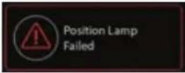 | This feature monitors the parking lamp and warns the driver when lamp is malfunctioning | User has to take the vehicle to Authorized Tata motors service station |
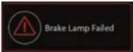 | This feature monitors the brake lamp and warns the driver when lamp is malfunctioning | User has to take the vehicle to Authorized Tata motors service station |
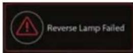 | This feature monitors reverse Lamp state and warns the driver when lamp is malfunctioning | User has to take the vehicle to Authorized Tata motors service station |
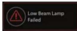 | This feature monitors the Low beam lamp state and warns the driver when lamp is malfunctioning | User has to take the vehicle to Authorized Tata motors service station |
 | This feature indicates the status of Auto light on IC | Information |
DASHBOARD AND FEATURES
| Display Message | Description | Action by the User | |
 | This warning shall come when already there is an drive mode change in Progress | User has to wait till the earlier mode transaction to be complete. | |
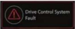 | This warning shall come when there is a drive mode switch failure. | User has to take the vehicle to Authorized Tata motors service sta-tion | |
 | HDC System Set Speed | Information | |
 | This screen comes when more than one warnings are true simultaneously. | Information | |
| Driver Information | System Image | Description | |
| Service Reminder |  | There are two types of service reminder i) By days ii) By KmsBy KmsThe service reminder shall come at every 10000 kms and it shall be pop up before 500kms of due (i.e. 10000-500=9500km) and it shall be subtracted from the distance travelled. | |
 | By DaysThe service reminder shall come at every 180days and it shall be pop up before 30 days of due time(i.e. 180-30=150 days) and it shall be subtracted from the days crossed. | ||
 | By Kms overdueThe service reminder overdue shall come if the due km is crosse and it shall be displayed in every IGN ON and it shall be minimised in the TFT (i.e. 10000-10050=50km) | ||
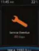 | By days overdueThe service reminder overdue shall come if the due days is crossed and it shall be displayed in every IGN ON and it shall be minimised in the TFT (i.e. 180-260=80 days). | ||
DASHBOARD AND FEATURES
| Driver Information | System Image | Description |
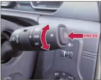
| Service Reminder Resetting | 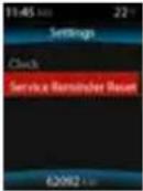 | User can reset service reminder by using the following stepsStep 1: By changing the DIC switch to select the SET screen |
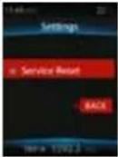 | Step 2: Short press the toggling switch to select the “Service Reminder Reset” and long press the toggling switch for more than 3 sec then the service reminder shall be reset and it shall not be displayed in the next Ignition cycle.Step 3: Select the back button by short pressing the toggling switch to go back to previous menu or don’t change/move the DIC switch for 10 sec to go back to previous screen.Note:Take it to the authorized TATA service station between the regular intervals of service reminder notification Days/Km in the screen and do not reset the service reminder before the service, and it shall be reset by the Authorized person during the service. |
| Driver Information | System Image | Description | |
| Distance to empty (DTE) | 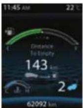 | 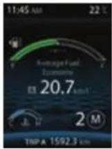 | It indicates approximate distance in ‘km’ that your vehicle can travel with available fuel in tank and the driving pattern.DTE values may vary significantly based on driving conditions, driving habits and condition of the vehicle. It is an estimate value of the available driving distance.‘Refuel’ shall be displayed which indicates that it’s the time to take your vehicle to the nearest filling station to fill the fuel.If low fuel warning light turns ‘ON’, fill the fuel tank immediately regardless the value of displayed DTE.NOTE:If DTE is displayed as ‘---’, take your vehicle to TATA MOTORS authorized service centre. |
| MT | AT | ||
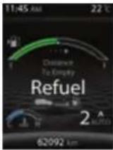 Refuel Refuel | |||
DASHBOARD AND FEATURES
| Driver Information | System Image | Description | |
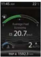
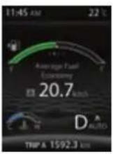
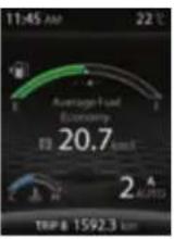
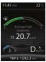
| Average fuel economy (AFE) | TRIP A | Instrument Cluster displays ‘Average Fuel Economy A’ and ‘Average Fuel Economy B’ corresponding to ‘TRIP A’ and ‘TRIP B’ respectively. Average Fuel Economy ‘A’ and ‘B’ will reset to ‘O’ when Trip A and Trip B is reset respectively. It will be displayed as ‘--.-’ for initial 0.5 km of respective trip. Once 0.5 km distance is covered, Average Fuel Economy will be displayed. NOTE: AFE value is estimate of fuel economy. It may vary significantly based upon driving conditions, driving habits and condition of vehicle. | |
 |  | ||
| MT | AT | ||
| TRIP B | |||
 |  | ||
| MT | AT | ||
| Instantaneous fuel economy (IFE) | 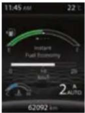 | 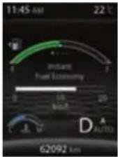 | It indicates fuel economy of current or instant fuel mileage of the vehicle when ignition is turned ‘ON’ and vehicle is on running condition.The indication on the display may be delayed if fuel consumption is affected by driving pattern.NOTE: IFE will vary frequently as per driving pattern. |
| MT | AT | ||
| Clock | 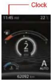 | Indicates current time in 12/24 hrs. mode. Clock time can be changed using setting menu when combi-switch is in ‘SET’ mode and by long and short pressing the TRIP switch.Whenever the battery terminals or related fuses are connected you must reset the clock time. This feature is available when ignition switch is in ‘ON’ position.NOTE: Clock settings can also be changed through infotainment system. For more information refer infotainment manual. | |
DASHBOARD AND FEATURES
| Driver Information | System Image | Description | |
| Clock Setting | 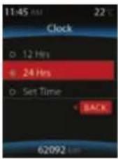 | You can set clock for 24/12 hrs mode along with hours and minutes values with this menu | |
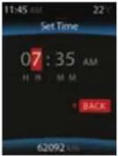 | 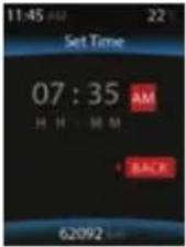 | Follow below procedure for clock settingStep 1: Long press the toggling switch to select the 12/24 hrs mode.Step 2: If you want to change to 12 hrs mode then long press the toggling switch to set the clock.Step 3: The digit has been highlighted in RED co our can be changed by short pressing the toggling switch.Step 4: You can move to the next digit by long pressing the toggling switch.Step 5: Once the time has been set then select the back button to go back to the previous screen by long pressing the toggling switch or No change in the DIC switch for 10 sec shall take to previous screen. | |
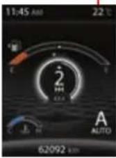
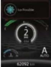
| Outside ambient temperature | Outside Ambient Temperature | This displays outside ambient temperature.The outside ambient temperature value may not be accurate when driving vehicle at low speed (less than 30kmph) or when stopped.If outside temperature falls below -1°C “snow-flake symbol along with Ice Possible” warning appears in addition to the outside temperature display on the screen. The warning flashes for approximately 3 seconds.NOTE: If display shows ‘--’, Contact nearest TATA MOTORS authorized service centre. | |
 | |||
 | |||
DASHBOARD AND FEATURES
TRIP, FUEL, SET Modes
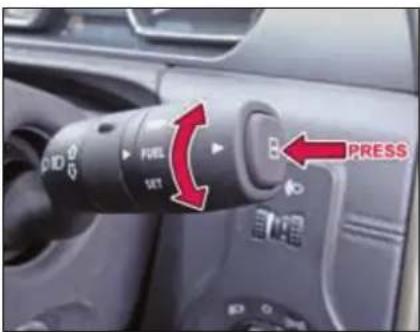
| Display selection in ‘TRIP’ Mode | |||
| Sr. No. | Indication on Display | ‘Selector switch’ (Short press) | ‘Selector switch’ (Long press) |
| 1 | Main Odometer | Display changes to Trip meter ‘A’ | - |
| 2 | Trip meter ‘A’ | Display changes to Trip meter ‘B’ | Resets Trip meter ‘A’ value |
| 3 | Trip meter ‘B’ | Display changes to Main Odometer | Resets Trip meter ‘B’ value. |
Display selection in 'FUEL' Mode
| Sr. No. | Indication on Display | ‘Selector switch’ (Short press) | ‘Selector switch’ (Long press) |
| 1 | Instant Fuel Economy | Display changes to Average Fuel Economy ‘A’ | No change |
| 2 | Average Fuel Economy ‘A’ | Display changes to Average Fuel Economy ‘B’ | - |
| 3 | Average Fuel Economy ‘B’ | Screen will go to DTE | - |
| 4 | Distance To Empty | ---- | No change |
| Display selection in ‘SET’ Mode | |||
| 1 | Clock | Display changes to Service Reset Mode(if service reminder appears) | Enters into 24/12 hrs selection |
| 2 | Service Reminder Reset | Display changes to clock setting | Enters into Service Reminder Reset mode |
Display selection in 'SET' Mode
Instrument Cluster
(for selected variants only)
NOTE: All indicators shown may not be applicable to your vehicle.
DASHBOARD AND FEATURES
Instrument Cluster
The Instrument cluster consists of Speedometer, Tachometer, Temperature gauge, Fuel gauge, and Warning lamps.
The instrument cluster also houses the Driver Information Centre. It consists of:
1) Main Odometer
- Odometer indicates total distance traveled by vehicle up to 999999 km with the resolution of 1 km.
- The Odometer reading freezes when reach to maximum value
2) Speedometer
- Speedometer indicates the actual vehicle speed in km/h.
3) Tachometer
- Tachometer indicates engine speed in revolutions per min (rpm).
4) Trip meter (A and B)
5) Fuel Computer.
It displays:
- Instantaneous Fuel consumption
It indicates fuel economy of current Drive when Ignition is turned 'ON'.
The display does not show actual value unless vehicle is moving.
• Average Fuel Consumption
Instrument Cluster displays 'Average Fuel Economy A' and 'Average Fuel Economy B' corresponding to 'TRIP A' and 'TRIP B' respectively. Average Fuel Economy 'A' and 'B' will reset to 'O' when Trip A and Trip B is reset respectively.
- Range (Distance to Empty)
It indicates approximate distance in 'km' that your vehicle can travel with available fuel in tank.
6) Outside Ambient Temperature
This displays outside ambient temperature in units of ^ C with the resolution of 1 ^ C.
Driver Information Centre
| Sr. No. | Parameter | Characteristics |
| 1 | Multifunctional Display | Colour: Blue text with black background |
| 2 | Main Odometer | Range: 0 to 999999Resolution: 1 kmThe Odometer reading does not over flow to ‘0.0’ when maximum value is reached, the display will freeze to maximum value. |
DASHBOARD AND FEATURES
| Sr. No. | Parameter | Characteristics |
| 3a | Trip Meter (A&B) | Range: 0.0 to 9999.9(5 digits)Resolution: 0.1 kmTrip meter reading becomes ‘0.0’ after it crosses 9999.9 kms. |
| 3b | Trip Meter reset | Trip meter (A & B) are reset by pressing ‘Trip’ switch when the particular Trip-meter is selectedDIC switch should be in ‘Trip’ mode. |
| 4 | Fuel Computer - Instantaneous Fuel Consumption | Range: 0.0 to 99.9 (3 digits)Resolution: 0.1 km/l or L/ 100 km |
| 5a | Fuel Computer - Average Fuel Consumption(A & B) | Range: 0.0 to 99.9 (3 digits)Resolution: 0.1 km/l or L/100 km |
| Sr. No. | Parameter | Characteristics |
| 5b | Average Fuel Consumption reset | When Trip meter ‘A’ or ‘B’ is reset, the Average Fuel Consumption ‘A’ or ‘B’ for that particular Trip meter also will get reset.Display Information Control (DIC) switch should be in ‘Trip’ mode. |
| 6 | Fuel Computer - Range(Distance to Empty) | Range: 0 to 999 |
| 7 | Outside Ambient Temperature | Range: -199 to +199 (2 1/2 digits, leading zero’s shall be suppressed) |
DASHBOARD AND FEATURES
Driver Information in TRIP, FUEL, SET Modes
In TRIP Mode
| Display selection by ‘Selector’ switch | |||
| Sr.No. | Indication on Display | If ‘selector’ switch is pressed & released immediately (Short Press) | If ‘selector’ switch is pressed & released after a delay (Long Press) |
| 1 | Main Odometer and Trip meter ‘A’ | Display changes to Trip meter ‘B’ with Main Odometer | Resets Trip meter ‘A’ value and Average Fuel Consumption ‘A’ value |
| 2 | Main Odometer and Trip meter ‘B’ | Display changes to Trip meter ‘A’ with Main Odometer | Resets Trip meter ‘B’ value |
In FUEL Mode
| Display selection by ‘Selector’ switch | |||
| Sr. No. | Indication on Display | If ‘selector’ switch is pressed & released immediately (Short Press) | If ‘selector’ switch is pressed & released after a delay (Long Press) |
| 1 | Range (Distance to Empty) | Display changes to Average Fuel Consumption ‘A’ | - |
| 2 | Average Fuel Consumption ‘A’ | Display changes to Average Fuel Consumption ‘B’ | - |
| 3 | Average Fuel Consumption ‘B’ | Display changes to Instantaneous Fuel Consumption | - |
| 4 | Instantaneous Fuel Consumption | Display changes to Average Trip Speed | - |
| 5 | Outside Ambient Temperature | Display changes to Range | - |
In SET Mode
| Display selection by ‘Selector’ switch | |||
| Sr. No. | Indication on Display | If ‘selector’ switch is pressed & released immediately (Short Press) | If ‘selector’ switch is pressed & released after a delay (Long Press) |
| 1 | Select Units | Display does not change. | Cluster enters into ‘Distance unit selection’ mode. (Refer below section) |
| 2 | Language Selection (only for export market) | Display changes to ‘Unit Selection’ mode. | Cluster enters into ‘Language selection’ mode. (Refer below section) |
Switch Functions: Distance Unit Selection (If applicable)
| Display selection by ‘Selector’ switch | |||
| Sr. No. | Indication on Display | If ‘selector’ switch is pressed & released immediately (Short Press) | If ‘selector’ switch is pressed & released after a delay (Long Press) |
| 1 | Distance Units | Displays distance unit as ‘miles’ with arrow mark. | Display changes to ‘Fuel unit selec-tion’ mode. |
| 2 | Distance unit with ‘miles’ | Displays ‘Setting Saved’ for 3 secs. (i.e. Dis-tance unit selected is ‘miles’) & display changes to ‘Fuel unit selection’ mode. | Displays distance unit as ‘km’ with arrow mark. |
| 3 | Distance unit with ‘km’ | Displays ‘Setting Saved’ for 3 secs. (i.e. Dis-tance unit selected is ‘km’) & display changes to ‘Fuel unit selection’ mode. | Displays distance unit as ‘miles’ with arrow mark. |
DASHBOARD AND FEATURES
Switch Functions: Fuel Unit Selection (If applicable)
| Display selection by ‘Selector’ switch | |||
| Sr. No. | Indication on Display | If ‘selector’ switch is pressed & released immediately (Short Press) | If ‘selector’ switch is pressed & released after a delay (Long Press) |
| 1 | Fuel Units | Displays Fuel unit as ‘L/100 km’ with arrow mark. | Display changes to ‘Temperature unit selection’ mode. |
| 2 | Fuel unit with ‘L/100 km’ | Displays ‘Setting Saved’ for 3 secs. (i.e. Fuel unit selected is ‘L/100km’) & display changes to ‘Temperature unit selection’ mode. | Displays Fuel unit as ‘MPG’ with arrow mark. |
| 3 | Fuel unit with ‘km/l’ | Displays ‘Setting Saved’ for 3 secs. (i.e. Fuel unit selected is ‘km/l’) & display changes to ‘Temperature unit selection’ mode. | Displays Fuel unit as ‘L/100 km’ with arrow mark. |
Switch Functions: Temperature Unit Selection (If applicable)
| Display selection by ‘Selector’ switch | |||
| Sr. No. | Indication on Display | If ‘selector’ switch is pressed & released immediately (Short Press) | If ‘selector’ switch is pressed & released after a delay (Long Press) |
| 1 | Temperature Units | Displays Temperature unit as ‘°C’ with arrow mark. | Display changes to ‘Unit selection’ mode. |
| 2 | Temperature unit with ‘°C’ | Displays ‘Setting Saved’ for 3 secs. (i.e. Temperature unit selected is ‘°C’) and display changes to ‘Unit selection’ mode. | Displays Temperature unit as ‘°F’ with arrow mark. |
| 3 | Temperature unit with ‘°F’ | Displays ‘Setting Saved’ for 3 secs. (i.e. Temperature unit selected is ‘°F’) and display changes to ‘Unit selection’ mode. | Displays Temperature unit as ‘°C’ with arrow mark. |
Warning Lamps
| Tell Tales | Color | Indication | Remarks |
| Malfunction Indication Lamp (MIL) | Amber | 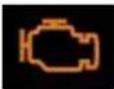 | 1. Illuminates when ignition is switched ‘ON’ and goes ‘OFF’ after 4 seconds.2. It remains ‘ON’ for any engine related fault that may increase emission levels of the vehicle beyond the regulatory norms. Contact a TATA MOTORS Authorised Service Centre for rectification. |
| Check Engine | Amber | 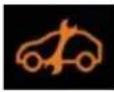 | 1. Illuminates when ignition is switched ‘ON’ and goes ‘OFF’ after 4 seconds.2. Illuminates continuously if a fault arises in Engine Managemen System. Contact a TATA MOTORS Authorised Service Centre. |
| Immobilizer | Red | 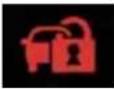 | 1. Illuminates when the system disables engine start if the original key is not used.2. Lamp blinks: Vehicle is in immobilized condition when key is not inserted.3. Lamp ON: Problem with key/system. Contact a TATA MOTORS Authorised Service Centre. |
| Water in fuel | Amber |  | 1. Illuminates when ignition is switched ‘ON’ and goes ‘OFF’ approx. in 3 seconds.2. This lamp blinks continuously along with chime if excess water is accumulated in the fuel filter. Contact a TATA MOTORS Authorised Service Centre to drain the water immediately to avoid serious damage to the fuel injection system. |
DASHBOARD AND FEATURES
| Tell Tales | Color | Indication | Remarks |
| Pre-Heat/Glow Plug indicator | Amber |  | 1. Illuminates when ignition key is in ‘ON’ position.2. Engine shall be started only after this indicator goes ‘OFF’. |
| Turn Signal | Green |  | Indicates direction indicated by the turn signal.Blinks along with buzzer while operating left/right turn indicator only when ignition is switched ‘ON’. The direction indicator arrow on In-strument Cluster flashes along with external indicator lights as selected. Both telltales shall blink simultaneously when Hazard switch is pressed irrespective of Ignition ON and the Tick-Tock sound shall be given when any one or both the telltales are ON. |
| High Beam | Blue | 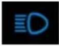 | Illuminates when the high beam headlamps are switched ‘ON’ or flashed. |
| Low Oil Pressure | Red | 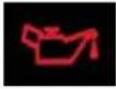 | 1. Illuminates when ignition is switched ‘ON’ and goes ‘OFF’ once required engine oil pressure is developed after starting the engine.2 If the low oil pressure indicator does not glow or remains ‘ON’ with the ‘IGN’ ‘ON’ and engine is running, it indicates a fault in the electrical circuit / lubrication system. Contact a TATA MOTORS Authorised Service Centre. |
| Battery charging | Red |  | Illuminates when ignition is switched ‘ON’. Once engine is started, it turns ‘OFF’.If it remains ‘ON’ while the engine is running, it indicates that the battery is not getting charged. Switch off all unnecessary electrical equipment and Contact a TATA MOTORS Authorised Service Centre. |
| Park Brake / Brake Fluid Low / EBD Fault | Red |  | Illuminates momentarily when ignition is switched ‘ON’. Once parking brake is released, it turns ‘OFF’. If it remains ‘ON’, it indicates1. Brake fluid level is low.2. Park brake is applied & turns ‘OFF’ when it is released.3. Fault in EBD (Electronic Brake force distribution) system |
| ABS | Amber | 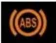 | Illuminates when ignition is switched ‘ON’ and goes ‘OFF’ in 4 seconds. Illuminates continuously if there is any malfunction in ABS. Normal braking system will be operational without assistance of ABS. Contact a TATA MOTORS Authorised Service Centre immediately. |
| Seat belt warning | Red | 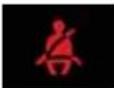 | Seat belt warning indicator comes ‘ON’ for 4 seconds, when ignition is turned ‘ON’. Lamp shall be made ‘ON’ continuously for 30 sec, if seat belt is not fastened the lamp will be ‘ON’ continuously without audio alarm till vehicle speed reaches 16 km/h. When vehicle speed exceeds above 16 km/h, the lamp will continue to flash with intermittent audio alarm. Once the seat belt is fastened, the buzzer and warning indicator shall go ‘OFF’. |
DASHBOARD AND FEATURES
| Tell Tales | Color | Indication | Remarks |
| Airbag status | Red |  | Illuminates when ignition is switched ‘ON’ and goes ‘OFF’ in approx. 4 seconds.If it will continuously illuminate or blinks then Contact a TATA MOTORS Authorised Service Centre immediately. |
| Front Fog Lamp | Green |  | Illuminates when the front fog lamp is ‘ON’. |
| Rear Fog Lamp | Amber |  | Illuminates when the rear fog lamp is ‘ON’. |
| High Coolant Temperature | Red |  | Illuminates when ignition is switched ‘ON’ and goes ‘OFF’ in approx. 4 seconds.If the engine is overheating, this indicator blinks along with an audible buzzer at his stage Contact a TATA MOTORS Authorised Service Centre immediately. This symbol blinks along with audible buzzer when engine coolant temperature is more than normal. When engine coolant temp increases to hazardous level, telltale shall blink with RED color and it is accompanied by audio warning.Never remove the radiator pressure cap from the radiator when the engine is hot. Do not restart the engine until the problem has been duly attended. |
DASHBOARD AND FEATURES
| Tell Tales | Color | Indication | Remarks |
| Traction Control / ESP Indicator (if applicable) | Amber |  | This symbol illuminates when ignition is turned ‘ON’ for approximately 4 sec. and turns ‘OFF’. This symbol continues to remain ‘ON’ if there is a fault in the ESP/TCS system and it shall blink when intervention by ESP/TCS system is active. Take your vehicle to the nearest Tata Authorised Service Centre at the earliest. |
| Cruise Control (if applicable) | Green |  | Illuminates when ignition is switched ‘ON’ and goes ‘OFF’ after. 4 seconds. This symbol illuminates when you activate/ switch ‘ON’ the Cruis Control. |
| Daytime running lamps - DRL (if applicable) | Amber |  | Illuminates when ignition is switched ‘ON’ and goes ‘OFF’ after. 4 seconds. This symbol illuminates when the Day Time Running lamp is ‘ON’. |
| Low Fuel | Amber |  | Illuminates momentarily when ignition is switched ‘ON’. This symbol illuminates continuously if fuel level is low. Refill the fuel tank as soon as possible. NOTE: The warning light will start flashing if there is any fault in the fuel system. Contact a TATA MOTORS Authorised Service Centre immediately. |
DASHBOARD AND FEATURES
| Warning Lamps | Color | Indicator | Remarks |
| TOD (if applicable) | Amber |  | Illuminates momentarily when ignition is switched 'ON'. If it continues to remain 'ON' or if it comes 'ON' after Ignition on pre-check, it indicates a fault in the Transmission system. Take your car to a TATA Authorised Service centre. |
| Driver Door Open(if applicable) | -- |  | If the Driver's door is open or not properly closed, this symbol comes 'ON' once the ignition key is inserted. Please ensure all the door are properly closed before you start driving. |
| Co-Driver Door Open(if applicable) | -- | 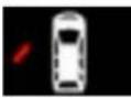 | If the Co-Driver's door is open or not properly closed, the corresponding door open indicator will come 'ON'. Please ensure all the doors are properly closed before you start driving. |
| Rear Left Door Open(if applicable) | -- | 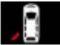 | If Rear Left Door is open or not properly closed, the corresponding door open indicator will come ON. Please ensure all the doors are properly closed before you start driving. |
| Rear Right Door Open(if applicable) | -- | 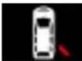 | If Rear Right Door is open or not properly closed, the corresponding door open indicator will come ON. Please ensure all the doors are properly closed before you start driving. |
| Tail Gate Open(if applicable) | -- |  | If Tail Gate is open or not properly closed, the corresponding door open indicator will come ON. Please ensure all the doors are properly closed before you start driving. |
Audio Reminders
The following are the Audible Reminder warnings provided to the user.
1) Key In reminder
While leaving your vehicle, if you forget key inside and Ignition is OFF, buzzer shall sound. Remove Key to stop the warning
2) Parking Lamp ON reminder
While leaving your vehicle, if user forget to turn OFF the Head/Park Lamps, buzzer shall sound. Switch off Parking Lamps to stop the warning.
WARNING

Ensure that parking lamps are switched off, else it might drain vehicle battery and will lead to Engine starting problem.
3) Parking Brake ON reminder
If Park Brake is applied and vehicle is driven above 5 Km/h, telltale shall blink along with chime continuously. Disengage the park brake to stop the warning.
4) Reverse Gear reminder
If reverse Gear engaged Buzzer shall sound to alert you. This chime is applicable for both Manual and AT transmission vehicles.
Headlamps
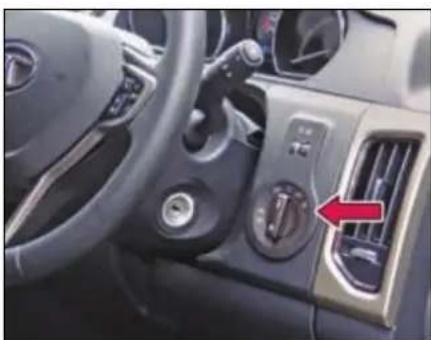
natural_image
Interior view of a car dashboard with air vent and control buttons (no visible text or symbols)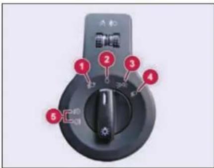
DASHBOARD AND FEATURES
1. Auto Light (if equipped)
The headlights will be automatically switched ON depending on ambient light conditions (while entering a tunnel or when it is twilight). For more details, refer 'DRIVER ASSIST' section.
2. OFF
All functions are 'OFF'. Day time running lamps (DRL) will be 'ON'. (if equipped)
3. Parking Lamp
Parking lamps are switched 'ON'.
4. Headlamp
Head lamps and Parking lamps are switched 'ON'. High beam/low beam can be selected using combi switch (Refer Combi switch section).
5. Fog Lamp (if equipped)
For switching 'ON' the Fog lamps, either the Head Lamp or Parking lamp must be 'ON'. Therefore, turn the knob to position 3 or 4.
The knob can be pulled / pushed in two positions to turn 'ON' / turn 'OFF' the fog lamps. First pull will turn 'ON' the front fog lamps and second pull switches 'ON' the rear fog lamps. Similarly, the first push will switch 'OFF' the rear fog lamps and second push will turn 'OFF' the front fog lamps.
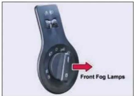
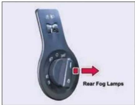
- Illumination control switch
- Headlamp leveling switch
DASHBOARD AND FEATURES
1) Illumination control switch
The function of Illumination control switch is to vary the brightness of backlit illumination of instrument cluster and switches in the cabin.
2) Headlamp levelling switch
Depending upon the number of occupants and luggage in the vehicle Headlamp focus may change. This can be adjusted by rotating the switch to one of the three level positions.
NOTE
When the low beam is switched ON, adjust the headlamp range to suit the vehicle load. Adjust when vehicle is stationary.
Day Time Running Lamps (DRL) (if equipped)
natural_image
Close-up of a blue car's front bumper with a clear light fixture (no visible text or symbols)Day time Running Lamps (DRL) are used to increase the visibility of the vehicle to other drivers during daytime.
DRL Activates when:
Ignition switch is in ON position and Head Lamp rotary switch in OFF position.
Automatic DRL Deactivation and Activation
You can disable or enable the DRL function.
To Deactivate -
Keep the Ignition switch in ON position & switch ON-OFF parking lamp twice within approx. 3 seconds.
To Activate -
Keep the Ignition switch in ON position & switch ON-OFF parking lamp twice within approx. 3 seconds.
DASHBOARD AND FEATURES
Combi-Switch (LH Stalk)
0) OFF position
The wiper is switched 'OFF'.
1) Intermittent wipe
Push the stalk upwards to operate intermittent wipe.
Inner rotary switch on left hand stalk is provided for intermittent front wiper delay. The switch has 5 delay timers.
2) Slow Wipe
Push the stalk towards position (2) for continuous slow wipe.
3) Fast Wipe
Push the stalk towards position (3) for continuous fast wipe.
4) Flick Wipe (spring return)

Pull the stalk downwards and hold it for continuous wipe, the wiper continuously
wipes across the windshield at low speed till the stalk is released.
5) Front windshield wash and wipe

➢ Pull the lever little longer, washer fluid will be sprayed on the wind-shield.
The windshield wipers operate for 3 cycles after the lever is released and 1 more cycle after approx. 5 seconds.
NOTE
When you crank the engine, the supply to washer motor is briefly cut off.
WARNING

If you operate wash and wipe function for more than approx. 30 seconds the controller cuts off the supply to washer motors to avoid overheating.
6) Rear windshield wash and wipe
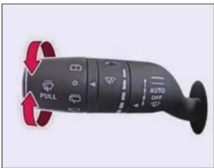
Turn the outer rotary knob such that it aligns its position with arrow mark and hold it, to operate rear windshield wash and wipe.
It will return to 'OFF' position as soon as released.
Rear intermittent wipe
Turn the outer rotary knob and align to position with arrow mark to operate rear intermittent wiper. Rear wiper will start wiping intermittently.
Rear wiper continuous 'ON'
Turn the rotary knob and align to position with an icon mark to operate the rear wiper in continuous mode.
NOTE
Rear wiper will not operate if tailgate is open.
Auto front wipe (if equipped)
If your vehicle is fitted with a Rain and Light Sensor, Auto Front Wipe is activated only when the wiper stalk is in the 'Auto' position. The wipe sensitivity can be altered with the help of intermittent wipe rotary switch.
For more details, please refer 'DRIVER ASSIST' - Rain and Light sensors' section.
NOTE
Turn the ignition switch to 'ON' position, to operate all wash and wipe functions. All functions pauses temporarily, when the engine is being cranked and resumes its function once cranking is complete.
WARNING

- Do not operate the windshield wipers, when the windshield is dry or obstructed.
- Always check and top up the windshield washer fluid in the container.
- Get the front and rear washer nozzles cleaned periodically.
DASHBOARD AND FEATURES
Combi-Switch (RH Stalk)
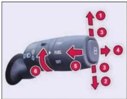
1. Left Turn signal
Move the lever fully upward.
2. Right Turn signal
Move the lever fully downward.
3. Lane Change Signal
To signal a lane change, move the lever slightly up or down to the point where the turn signal light begins to flash, but the lever does not latch. The turn signal will flash 3 times automatically.
4. Hi-Beam
To switch over head lamps to hi-beam:
➢ Turn the master light switch to head lamp position.
➢ Push the lever away from steering wheel.
➢ Hi-beam headlamps and instrument cluster tell-tale will turn 'ON'.
To switch over from high beam to low beam, PULL the lever back towards the steering wheel.
5. High beam Flash (spring return)
To flash the high beam, pull the lever towards you from the normal position. It will return to its normal position when you release it.
6. TRIP, FUEL, SET functions
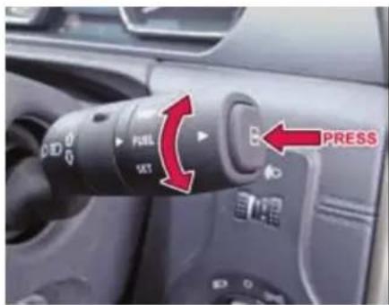
By rotating the outermost ring of the Combi Switch, you can set the TRIP, FUEL and SET functions that are displayed on the instrument cluster. To reset/scroll the values, press the outermost selector switch on the stalk.
For more details, please refer 'Driver Information Screen' section.
Fascia Switches
Fascia switches are provided on the center console above HVAC control panel.
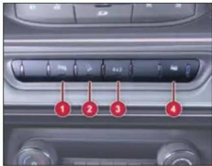
- Rear Park Assist Switch (If applicable)
- Hill Descent Control (HDC) Switch (If applicable)
- 4 x 2 Switch (If applicable)
- Door Lock / Unlock Switch
1. Rear Park Assist Switch

Reverse park assist system gets activated when you engage reverse gear with a simultaneous beep sound. The intensity of the beep keeps on increasing as your
vehicle comes closer to the obstacle. Press the switch to mute the beep.
NOTE
Reverse park assist switch can be used to turn 'ON' the Rear View Camera (if equipped) even if vehicle is not in reverse gear.
2. Hill Descent Control (HDC) Switch

Activate the HDC for a smooth and controlled hill descent by enabling the vehicle to use the ESP to control the speed of each wheel.
For detailed information on Hill Descent Control (HDC) refer 'DRIVER ASSIST' section.
3. 4 x 2 Switch (if equipped)

A switch is provided to select 4x2 or 4x4 mode.
| Mode | LED | TOD |
| 4x2 | ON | Disabled |
| 4x4 | OFF | Enabled |
4. Door Lock / Unlock Switch

Press the Lock/Unlock switch to lock/unlock all the doors.
Mic
A mic is provided on roof interior for phone calling and voice command.
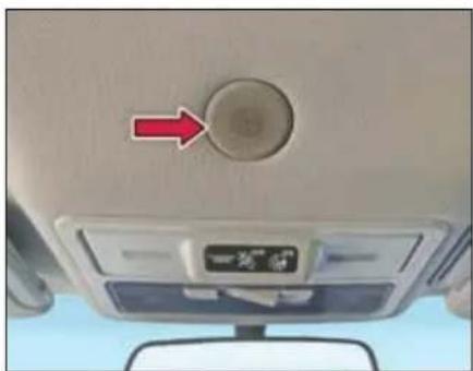
natural_image
Interior view of a car dashboard with a circular knob and directional arrow (no text or symbols visible)DASHBOARD AND FEATURES
Steering Wheel Switches (LHS)
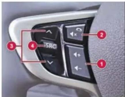
1. Volume
Press to increase and to decrease volume of music system/radio.
2 Mute / phone reject
To reject or hang up a phone call. It is also used to mute the volume of music system/radio.
3. Seek forward / backward
To change radio channels.
- Source - SRC Press to select the required source in the infotainment (USB, AUX, AM, FM).
Steering Wheel Switches (RHS)
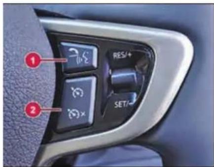
1. Phone receive / PTT (if equipped)
This button is used to accept incoming call when a cell phone is connected via Bluetooth.
Push to talk (PTT) will enable the info-tainment head unit in voice command and reception mode from the user.
2. Cruise control switches
For detailed information on cruise control steering switches refer Cruise Control in 'DRIVER ASSIST' section.
NOTE
For detailed information on steering wheel switches refer infotainment manual.
Infotainment System
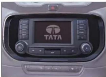
natural_image
Interior view of a car dashboard with the TATA logo displayed on the screen (no readable text beyond branding)NOTE
For more information on infotainment system refer infotainment manual.
Speakers
Speakers and tweeters are provided on models with infotainment system.
Audio Amplifier
(If applicable)
Audio amplifier is provided with two additional speakers (center speaker and subwoofer). Amplifier provides processed amplified output to all speakers, tweeter and subwoofer.
Power Socket
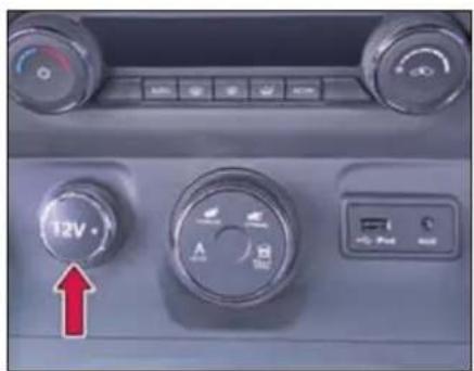
Front Power Socket
Three power sockets are provided at following locations:
- On Dashboard center console
- On 2 ^nd row center console- (If applicable)
- Luggage compartment- (If applicable)
The power socket will work when the ignition switch is in ACC or ON position. This socket can be used to provide 12V (10A) power for electrical accessories.
NOTE
Use of inappropriate electrical accessories can cause damage to your vehicle's electrical system. Make sure that any electrical accessories you use are designed to plug into this type of socket.
USB/AUX Port
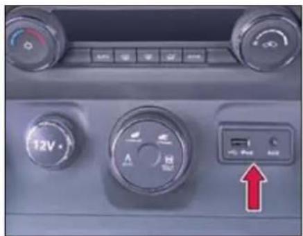
Front USB/AUX
Connect your portable digital music players, pen drives etc. to this socket for playing music tracks through the vehicles music system.
NOTE
Remove the plugged cables, devices every time after use or when not in use.
DASHBOARD AND FEATURES
Smart USB charger & Power Socket (if equipped)

- Power Socket
- Smart USB Charger
Smart USB charger is located on rear of center console.
The USB Charger provides current as per the charging requirement of connected device. It can charge devices that draw 5V/2.4A or less.
The charger has illumination for night time visibility.
NOTE
The smart USB charger shall be used only for USB charging. It does not support USB communication.
NOTE
Phone or tablet charging may vary from device to device.
WARNING

- Do not use excessive force while handling USB port.
- Avoid insertion of any hard, sharp or metallic object in the USB slot.
- Avoid spraying or spilling of cleaning solution, perfume, car fresheners, beverages, caustic chemicals or any liquid on USB slot.
- The engine should be running when using accessories for long period. Failure to do so can discharge the battery.
Boot Lamp/Power Socket (if equipped)
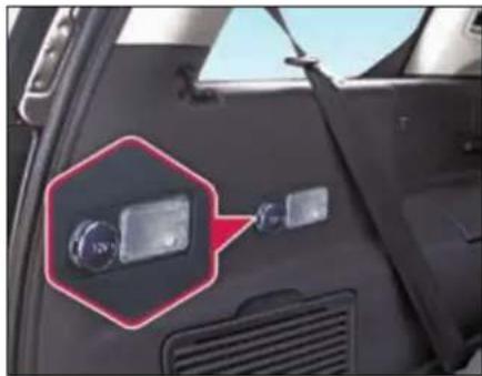
natural_image
Close-up of a car's front panel showing a mounted sensor or connector with a red annotation box (no visible text or symbols)Boot lamp is provided in the luggage compartment to illuminate the luggage area.
Switch is provided on lamp to turn ON/OFF.
You can connect your refrigeration kit, chiller etc. to the power socket provided in the luggage compartment.
Roof Lamps
Three interior roof lighting lamps are provided on the roof with inbuilt switch.
The central rectangular switch has three positions:
ON - The lamp will turn ON as long as the switch is in this position.

DOOR - In this position the lamp turns ON with dimming when either of the doors are

opened. When the last door is closed, the lamp will remain ON for approx. 25 sec and turns OFF with dimming. This helps settling in the seat and inserting the key in the ignitions switch. When the key is turned to the IGN position, the lamp goes OFF immediately.
OFF - In this position the lamp will remain OFF.

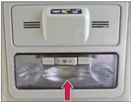
natural_image
Interior view of a white appliance with ventilation grilles and a red arrow pointing to a device (no visible text or symbols)Front roof lamp
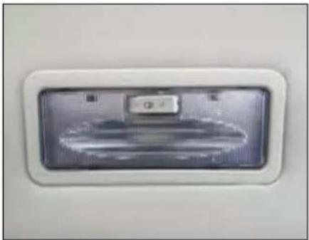
natural_image
Close-up of a white rectangular electronic device with a metallic panel and indicator lights (no visible text or symbols)Rear roof lamp
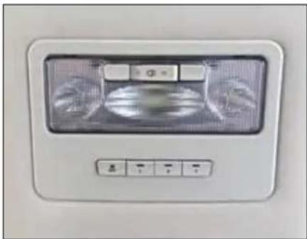
natural_image
Front view of a white ceiling fan with a digital display and control buttons (no visible text or symbols)Central roof lamp
DASHBOARD AND FEATURES
Sun Blinds - Rear Windows
(if equipped)
The sun blinds in the rear door trim pan-els can be pulled out and secured in the holders.
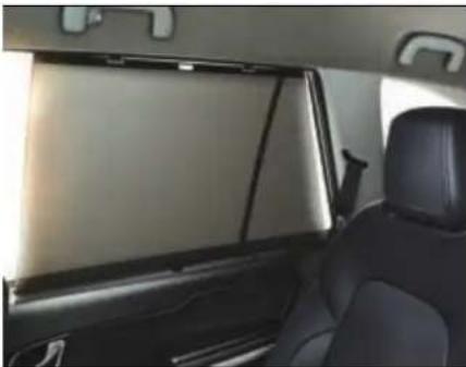
natural_image
Interior view of a car showing the rear seats and dashboard panel (no visible text or symbols)NOTE
Pull out sun blinds during the journey, only when door windows are closed.
When retracting the sun blinds disengage the sun blind from holders and carefully guide it back into the retractor roller.
STOWAGE AREAS
04
STOWAGE AREAS
Stowage Compartments
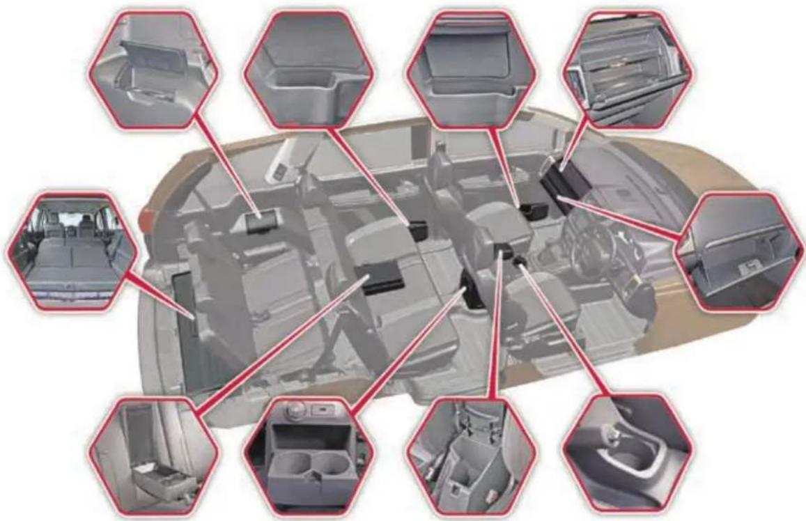
WARNING

Stow the objects/luggage correctly and secured properly, otherwise they can slide or be thrown around and hit vehicle occupants. There is a risk of injury, particularly in the event of sudden braking or a sudden change in direction.
• Always stow objects in such a way that the objects do not get thrown around during sudden braking.
- Always make sure that objects do not protrude from stowage spaces, parcel nets or stowage nets.
- Close the lockable stowage spaces before starting a journey.
- Stow and secure objects that are heavy, hard, pointed, sharp-edged, fragile or too large in the luggage compartment.
Top Stowage Compartment
A top stowage compartment is provided above the upper glove box, where you can keep small items.
There are two glove boxes located on the dashboard.
Chiller Glove Box
Upper Glove Box is provided with a cooling facility. It cools the glove box only when the front A/C is ON. Shut OFF the vent by rotating the knob, whenever cooling is not required.
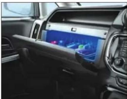
natural_image
Interior view of a modern car dashboard with a digital display showing navigation and vehicle settings (no visible text or symbols)The glove box lamp illuminates when the glove box is opened.
Lower Glove Box
Another glove box is provided below upper glow box. It can be locked with the ignition key.
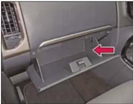
natural_image
Interior view of a car showing the dashboard and side panel with a red arrow pointing to a component (no text or symbols visible)NOTE
Make sure that glove box flap is closed while driving.
STOWAGE AREAS
Below The Arm Rest
Stowage space is provided below front arm rest. To access, press the knob and lift the arm rest.
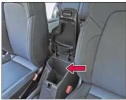
natural_image
Interior view of a car showing the rear seat, rear seats, and a car seatbelt with a red arrow pointing to the side (no text or symbols visible)Cup Holders
NOTE
Use cups, containers, bottles of right size and which have lids. The drinks could otherwise spill.
On Central Console
A single cup holder is provided on central console.
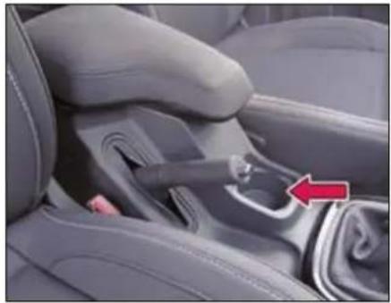
natural_image
Interior view of a car seatbelt with a red arrow pointing to the side panel (no text or symbols visible)Middle Row (Central Console)
Push the cover gently to open and access the cup holders.
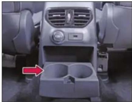
natural_image
Interior view of a car dashboard and infotainment unit (no visible text or symbols)Third Row Seat
Cup holders are provided on both sides for third row passengers. Lift the cover to access the cup holders.
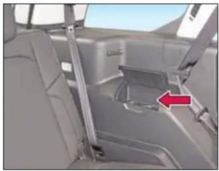
natural_image
Interior view of a car showing seatbelt and side panel, with a red arrow pointing to the side panel (no text or symbols visible)Foldable Arm Rest (if equipped)
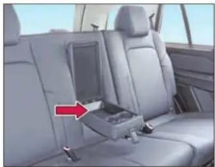
natural_image
Interior view of a car showing the seatbelt compartment with a red arrow pointing to it (no text or symbols visible)A foldable arm rest has been provided in the second row (60:40) seat. It also has two cup holders and a utility box, which can be accessed by opening the cover. When not required, fold the armrest back into the seat.
NOTE
Remove all items and cups before folding the cup holders.
Utility Pockets (front & rear doors)
Utility pockets are provided on front and rear doors and it can be used to keep magazines/books, water bottles etc.
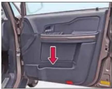
natural_image
Interior view of a car showing the door, vent, and side panel with a red arrow pointing to a specific area (no text or symbols visible)STOWAGE AREAS
Tailgate (Trunk) Compartment
Store the luggage in the trunk.
natural_image
Rear view of a silver SUV showing rear passenger compartments and trunk (no visible text or symbols)WARNING

Distribute the items of luggage as evenly as possible.
Position heavy loads as forward as possible and distribute evenly.
The load must not protrude above the luggage cover.
Never allow occupants to travel in the luggage compartment
Third row seat folding
You can increase the trunk capacity by folding the third row seats.
Pull the fabric hook and fold the seat backrest forwards. Both the seats can be independently folded to create extra luggage space.
natural_image
Interior view of a car showing rear seats and roof trusses (no visible text or symbols)Second row seat folding
For folding:
Keep the head restraint at its lowest position.
➢ Pull the backrest release hooks and fold the seat backrest forwards.
➢ Move the driver or front passenger seat forward if necessary.
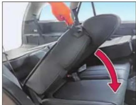
natural_image
Interior view of a car showing seatbelt and rear seats with a red arrow indicating direction (no text or symbols)Backrest unlocked
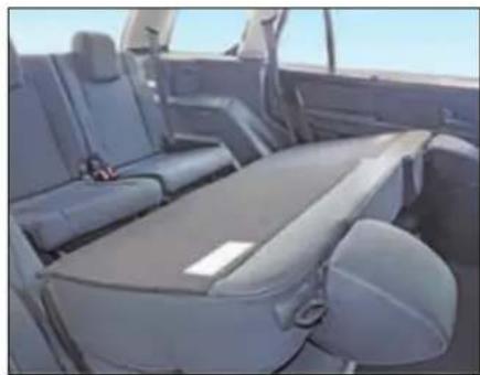
natural_image
Interior view of a car showing rear seats and seatbelt (no visible text or symbols)Backrest folded
WARNING

You should always engage the rear seat if you do not need the through loading feature.
If the rear seat and seat backrest are not latched they could fold forwards, e.g. when braking suddenly or in the event of an accident.
The vehicle occupant would thereby be pushed into the seat belt by the rear bench seat or by the seat backrest. The seat belt can no longer offer the intended level of protection and could even cause injuries.
Objects or loads in the trunk cannot be restrained by the seat backrest. There is an increased risk of injury.
Before every trip, make sure that the seat backrests and the rear seats are latched securely.
STOWAGE AREAS
To Access Third Row Seats
Fold the second row seat and pull the knob provided at the base of the seat.
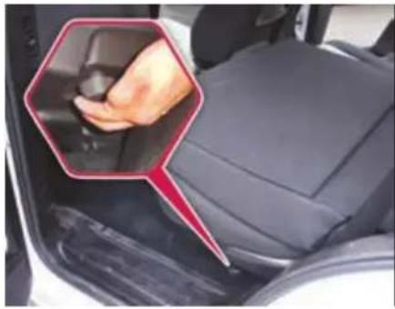
natural_image
Close-up of a car's side panel showing the grip and seat area, with a hand pointing to the grip (no text or symbols visible)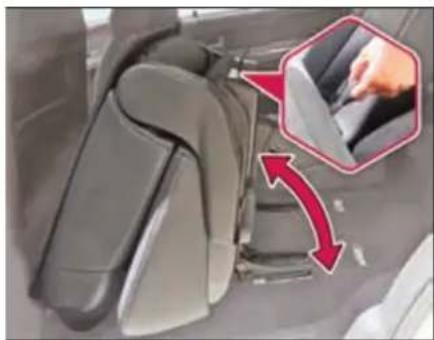
natural_image
Close-up of car seatbelt mechanism with red arrows indicating movement, no visible text or symbolsThe second row seat can be tumbled from its base by pulling the fabric hook located behind the seat's back.
While folding the second row seat after getting inside the third row seat, never keep your feet on the seat locking brackets.
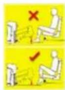
Coat Hook
Coat hooks are provided on second row side grab handles.
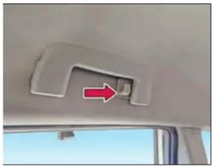
natural_image
Interior view of a vehicle showing a car's rear door and seat, with a red arrow pointing to the seat area (no text or symbols visible)WARNING

The coat hook cannot restrain heavy objects or items of luggage. Never hang hard, sharp edged or fragile objects on the coat hook.
Goggle Case
A goggle case is provided above the driver's door.
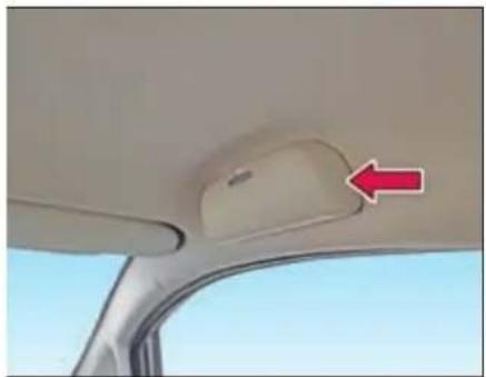
natural_image
Interior view of a car showing the rearview seat and windshield area with a red arrow pointing to the side (no text or symbols visible)CLIMATE CONTROL
05
CLIMATE CONTROL
The Climate control regulates the temperature set in the vehicle interior and filters dust particles.
Air is distributed through following air vents:
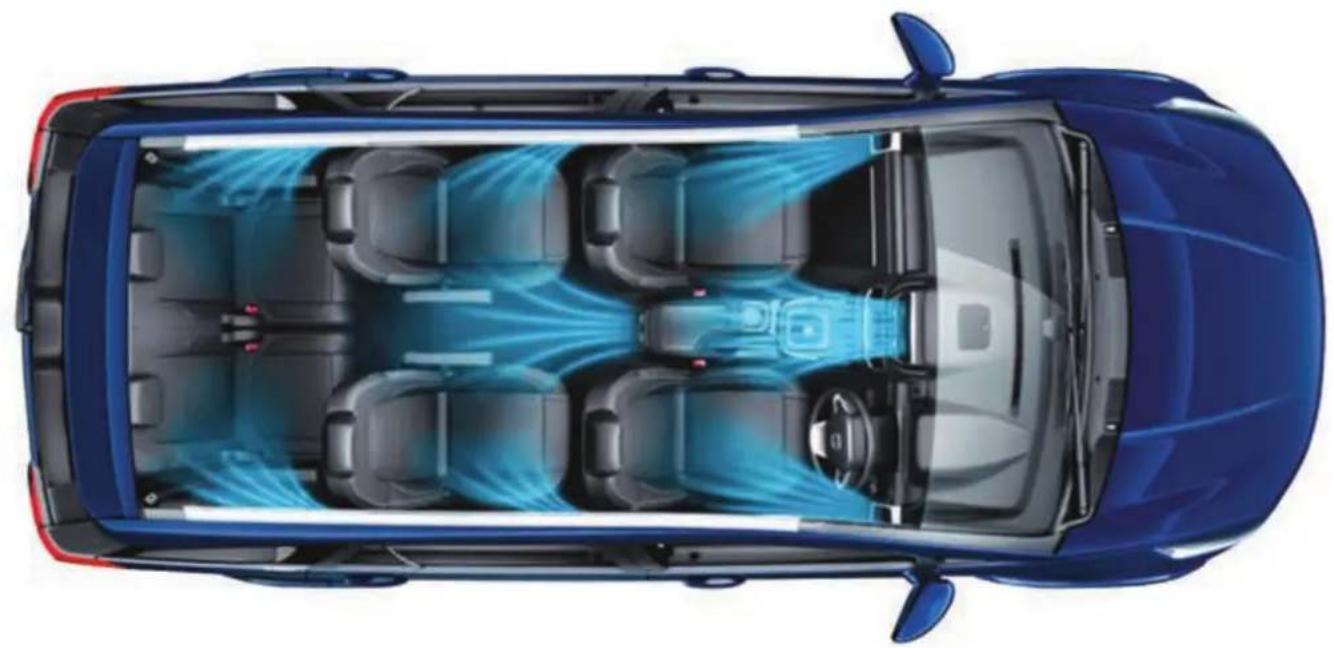
natural_image
Top-down architectural rendering of a blue car showing internal seating and airflow patterns (no text or symbols)Air Vents
Air flow and its direction can be adjusted with the help of knobs provided on respective vent.
Front air vents
Four air vents are provided on dashboard.
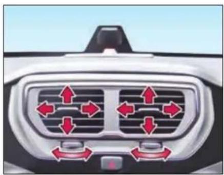
natural_image
Top-down view of a car's front grille with directional arrows indicating airflow or movement (no text or symbols)Center air vents
Front side air vents
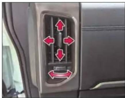
natural_image
Car interior air vent with red directional arrows indicating airflow or movement (no text or symbols)Second row center console air vents
Two air vents are provided on second row center console.
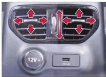
natural_image
Air conditioning air conditioner panel with red directional arrows indicating airflow or movement (no text or symbols)Rear side air vents
Side air vents (two each) are provided for second and third row occupants.
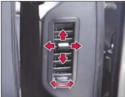
natural_image
Close-up of a car air vent with red directional arrows indicating airflow or movement (no text or symbols)Second row side air vents
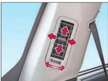
natural_image
Close-up of a car rear air vent with red directional arrows indicating airflow or movement (no text or symbols)Third row vents
CLIMATE CONTROL
Heating, Ventilation and Air Conditioning (HVAC)
The HVAC system is operational when engine is running and blower is ON. It regulates the temperature in the vehicle interior and filters dust particles.
Either of the following HVAC system is provided on your vehicle.
- Fully Automatic Temperature Control (FATC)
- Manual HVAC
Fully Automatic Temperature Control (FATC)
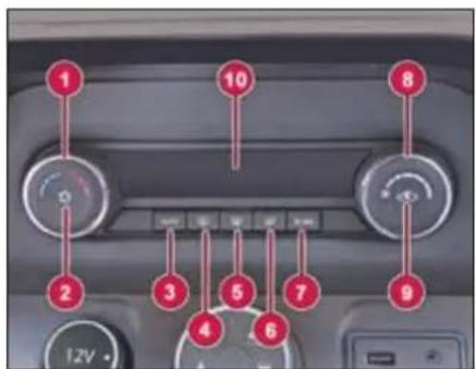
- Temperature Control Knob
- A.C. ON / OFF Button
- AUTO Mode Selection Button
- Demister / Heater Button (Rear)
- Windshield Defroster Button (Front)
- Air Distribution Mode Button
- ECON (Economy) Mode Selection Button
- Blower Speed Control Knob
- Recirculation Button
- Display
FATC system controls the in-cabin temperature of the vehicle automatically and provides maximum passenger comfort regardless of the outside weather conditions.
Automatic Operation

To put the climate control in fully automatic mode:
➢ Press the 'AUTO' button.
➢ Set the desired temperature by turning temperature control knob. The display will show all the functions during 'AUTO' mode.
The System automatically selects the proper mix of conditioned and / or heated air that will, as quickly as possible, raise or lower the interior temperature to your preference.
To come out of 'AUTO' mode, press 'AUTO' button again.
Semi-automatic Operation
Making any manual selection causes the word 'AUTO' in the display to turn off and overridden setting is displayed. System will remain in semi-automatic mode till 'AUTO' is pressed again.
A.C. ON/OFF Button

Press the A.C. ON/OFF button to turn the air conditioning ON or OFF. LED will glow when AC is ON.
NOTE
The AC will be switched 'ON' only if the blower is 'ON' and engine is running.
Temperature Control Knob
The temperature control dial allows you to adjust the temperature. Turn the dial counter-clockwise to lower the temperature. To increase the temperature, turn the dial in clockwise direction.
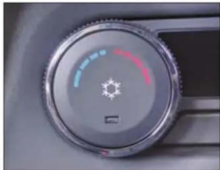
natural_image
Close-up of a car dashboard dial with a sun icon and color settings (no text or symbols visible)Air intake selector

Press the switch to activate / deactivate recirculation mode.
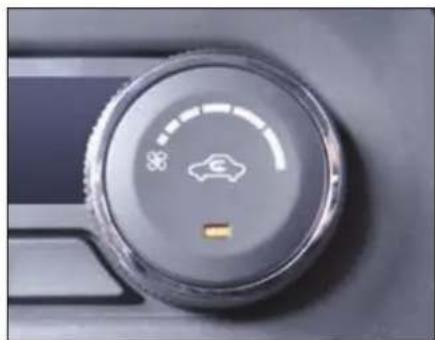
natural_image
Close-up of a car climate control dial with a car icon and speedometer (no text or symbols visible)Recirculation mode: (Indicator light ON)
Air in the passenger compartment recirculates. No fresh air enters the compartment.
Always use when:
- Driving on a dusty road or through tunnel.
- On signals or slow traffic to avoid traffic pollution.
• Maximum cooling is required.
Fresh Air mode: (Indicator light OFF)
Fresh air is drawn into the vehicle.
Always use when:
- Discomfort is felt or windows are fogging up.
- Using or air flow modes during demist / defrost.
• Using normal heating mode.
CLIMATE CONTROL
Blower Speed Control Knob
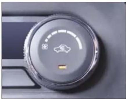
natural_image
Close-up of a car climate control dial with a star icon and a yellow button (no text or symbols visible)This is to turn 'ON' the blower and select desired blower speed.
In 'AUTO' mode, the FATC system will regulate the blower speed automatically.
To switch 'OFF' climate control system, turn the blower speed control knob in extreme counter clockwise direction.
NOTE
To avoid stale air and collection of mustiness, you should have the blower fan running at all times.
Air Distribution Control Button
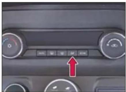
natural_image
Interior view of a car dashboard with control buttons and a red upward arrow indicator (no text or symbols)Press the button to select one of the following air distribution mode.
| Directs air through the center and side air vents | |
| Directs air through the center, side and foot well vents | |
| Directs air through the foot well air vents | |
| Directs air through the defroster & foot well vents (Default fresh air mode) | |
| Directs air through the defroster vents (Default fresh air mode) |
In AUTO mode, the FATC system will regulate the blower speed automatically.
However, user override is possible with the use of air distribution control button to select the desired airflow mode.
Each time you press the air distribution control button the display shows the mode selected.
NOTE
If the display flashes 'ERR' in periodic pattern (Display will show 'ERR' for 5 sec. and set temperature for 30 sec.) It indicates FATC malfunctioning. Switch over to manual mode and contact TATA MOTORS Authorized Service Centre.
Windscreen Defroster Button

(Front)
This button directs the main airflow towards windscreen for faster defrosting. It also overrides any mode selection you may have made.
When you select windscreen defroster button the system automatically switches to fresh air mode and turn on the A.C.
When you turn OFF the button again the system returns to its former settings.
NOTE
For your safety make sure you have a clear view through all the windows before driving.
Demister / Defogger Button

Press the demister button to activate rear windshield and outside rear view mirror (if equipped) demister. The system deactivates after 15 min of continuous operation.
You can also deactivate by pressing de-mister button.
ECON A.C.

During ECON A.C. operation, the system automatically cuts off compressor at a higher temperature than normal A.C. The operation can be used during mild weather conditions for better fuel efficiency. Comfort level may be compromised during this operation.
Sensors
FATC system is fitted with 3 sensors.
Solar Sensor
A solar sensor is provided on top of the dashboard on the right side of defrosts grill.
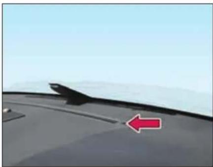
natural_image
Close-up of a car's front wheel with a red arrow pointing to the side (no text or symbols visible)In-Vehicle Sensor
In-vehicle sensor is located on the cover of instrument cluster.
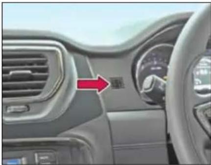
natural_image
Interior view of a car dashboard with air vent and steering wheel (no visible text or symbols)Outside ambient temperature sensor
Outside ambient temperature sensor is located behind front bumper grill.
WARNING

- Do not spill any liquid on sensors.
- Do not cover sensor, this may cause the sensor to malfunction. This may lead to FATC not functioning to desired level.
CLIMATE CONTROL
Manual Heating, Ventilation and Air conditioning (HVAC)
(if equipped)
The HVAC is operational when engine is running and blower is ON. The Climate control regulates the temperature in the vehicle interior and filters dust particles. You can manually set the desired temperature
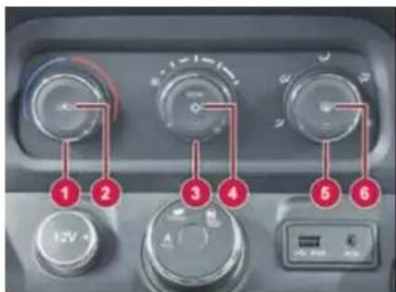
- Temperature Control Knob
- Recirculation Button
- Blower Speed Control Knob
- A.C. and Econ (Economy Mode) ON/OFF Button
-
Air Distribution Control Knob
-
Rear Defogger / Demister Button
The system has a separate auxiliary rear cooling system along with adjustable vents for 2^nd and 3^rd row occupants.
Temperature Control Knob
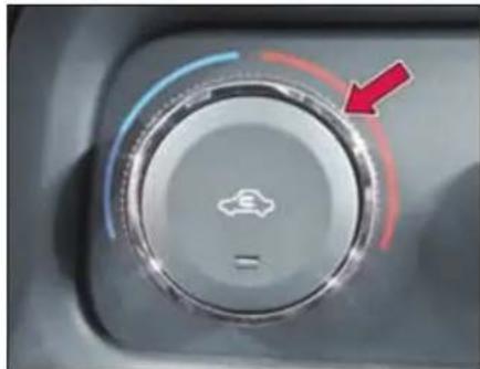
natural_image
Close-up of a car dashboard knob with a red arrow pointing to the left side (no text or symbols visible)The temperature control dial allows you to adjust the temperature. Turn the dial counter-clockwise to lower the temperature. To increase the temperature, turn the dial in clockwise direction.
Recirculation Button
Press the switch to activate / deactivate recirculation mode.
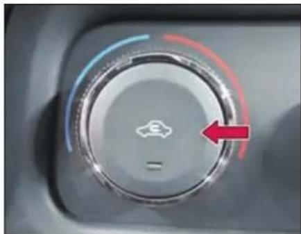
natural_image
Close-up of a car's dashboard dial with a red arrow pointing to the left side (no text or symbols visible)Recirculation mode: (Indicator light ON)
Air in the passenger compartment recirculates. No fresh air enters the compartment.
Always use when:
- Driving on a dusty road or through tunnel.
- On signals or slow traffic to avoid traffic pollution.
• Maximum cooling is required.
Fresh Air mode: (Indicator light OFF)
Fresh air is drawn into the vehicle.
Always use when:
- Discomfort is felt or windows are fogging up.
• Using 📋 or 🌐 air flow modes during demist / defrost.
• Using normal heating mode.
Blower Speed Control Knob
This is to turn ON the blower and select desired blower speed.
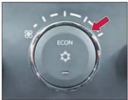
To switch OFF, turn the blower speed control knob in extreme counter clockwise direction
A.C. mode ON-OFF Button
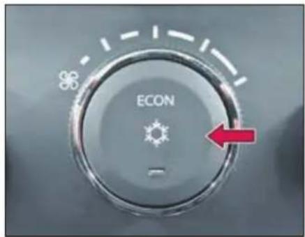
Press the switch to activate / deactivate the climate control. The indicator lamp in the button will light up when climate control is activated.
First Press: Normal A.C.is switched ON. Second Press: ECON mode turns ON with A.C.
Third Press: Both A.C. and ECON functions are switched OFF.
NOTE
The AC will be switched ON only if the blower is ON and engine is running.
When AC is switched ON, engine idling RPM increases marginally to adjust the AC compressor load.
When desired temperature is achieved AC trips OFF automatically.
CLIMATE CONTROL
Econ A.C
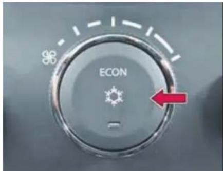
During ECON A.C. operation the system automatically cuts off at a higher temperature than normal A.C. The operation can be used during mild weather conditions for better fuel efficiency. Comfort level may be compromised during this operation.
Air Distribution Control Knob
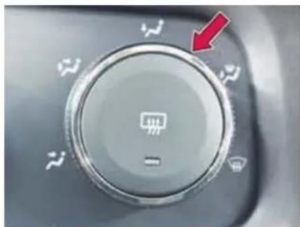
natural_image
Close-up of a car dashboard control knob with white icons and a red arrow pointing to it (no text or symbols on the knob itself)Press the button to select one of the following air distribution mode.
| Directs air through the center and side air vents | |
| Directs air through the center, side and foot well vents | |
| Directs air through the foot well air vents | |
| Directs air through the defroster & foot well vents (Default fresh air mode) | |
| Directs air through the defroster vents (Default fresh air mode) |
Demister / Defogger Button
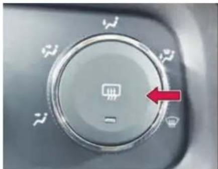
natural_image
Close-up of a car dashboard control knob with a red arrow pointing to the left side (no text or symbols visible)Press the button to turn ON the rear windshield and outside rear view mirror (if equipped) demister. This clears the fog / mist formation.
The indicator on the button turns ON when the rear demister is ON. The demister turns OFF automatically after 15 minutes.
You can also deactivate by pressing de-mister button.
Rear A.C. Operating instruction

Separate auxiliary unit is provided for rear AC.
Rear A.C. blower control switch is provided on the roof near interior lamp. Desired speed can be selected for second and third row occupants. The cool air will come when front A.C. is ON.
Keep air vents fully closed, when and where not required.
NOTE
- Condensation may drip from the underside of the vehicle when it is in cooling mode. Traces of water on the ground are normal and are not a sign that there is a malfunction.
- Ventilate the vehicle for a brief period during warm weather. This will speed up the cooling process and the desired vehicle interior temperature will be reached quickly.
- Never cover the air vents or air intake grilles in the vehicle interior.
- If the AC is not used for a long period, such as during winter, it may not give the best performance when you start using it again. Operate the AC at least once a month to maintain optimum performance.
- While starting the vehicle itself after long duration (more than 15 days), following procedure needs to be followed to meet AC
performance.
Start the vehicle with AC & Blower in OFF condition in idling for 2\~3 minutes.
Then switch ON the AC & Blower and run it for another 2\~3 minutes in idling for proper circulation of refrigerant & oil to lubricate the internal parts of AC system.
CLIMATE CONTROL
Recommended basic settings of the control elements of air conditioning system for the respective operating modes. These may vary depending on individual requirements and weather conditions.
| Functions | Control Knob Position | Button Position | |||
A. Air Flow Direction 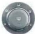 | B. Blower Speed 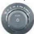 | C. Air Temperature 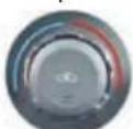 | D. Air Intake 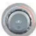 | E. AC ON / OFF 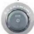 | |
| Normal heating |  | 2^nd or 3^rd position | Desired temperature | Fresh air mode | Switched OFF |
| Quick heating |  | To MAX speed and then 2^nd or 3^rd position | To the right up to the stop | Briefly switch ON to Fresh air mode then Recirculation mode | Switched OFF |
| Normal Cooling |  | 1^st to 3^rd position | Desired temperature | Recirculation mode | Switched ON |
| Quick Cooling | [HST4] | To MAX speed and then 2^nd or 3^rd position | To the left up to the stop | Recirculation mode | Switched ON |
| Demisting |  | 2^nd or 3^rd position | Desired temperature | Fresh air mode (Default) | Switched ON (Optional) |
| Defrosting |  | To MAX speed | Desired temperature | Fresh air mode (Default) | Switched ON (Optional) |
STARTING AND DRIVING
06
STARTING AND DRIVING
Pre Driving Checks
Make sure that:
- Windshield, windows, mirrors, lights, and reflectors are clean and unobstructed.
- Tools kit, jack & handle, warning triangle, owner's manual, first aid kit and vehicle documents are available and stored at their locations.
NOTE
Regularly check and replenish the first aid kit contents.
- All doors, engine bonnet and tail gate are securely closed and latched.
- All occupants are properly restrained and should always wear seat belts or use child restraints system.as applicable
- Objects, luggage or loads are secured properly against slipping or tipping.
- Rear seats are securely latched.
- Sufficient fuel for the trip.
WARNING

Objects in the driver's footwell can restrict the pedal travel or obstruct a depressed pedal. The operating and road safety of the vehicle is endanger. There is a risk of an accident.
Make sure that all objects in the vehicle are stowed correctly, and that they cannot enter the driver's footwell. Install the floor mats securely and as specified in order to ensure sufficient clearance for the pedals. Do not use loose floor mats and do not place floor mats on top of one another.
WARNING

Unsuitable footwear can hinder correct usage of the pedals, e.g.:
• shoes with thick soles
• shoes with high heels
- slippers
There is a risk of an accident.
Wear suitable footwear to ensure correct usage of the pedals.
Daily check:
- Tyres for abnormal wear, cracks or damage and embedded foreign material such as nails, stones, etc.
- Traces of fluid and oil leakage below vehicle.
NOTE
Water dripping from the air conditioning system after use is normal.
- All lamps, wipers, wiper blades and horn for proper operation.
- All switches, gauges and tell tales are working properly.
Adjust:
- Seats, head restraints (if equipped) and steering wheel position.
- All the mirrors properly.
Weekly check:
• Engine oil and coolant level
- Brake and steering fluid level
• Windshield washer fluid level
- Battery electrolyte level
NOTE
Check the tyre pressure regularly including spare wheel.
Driving Tips
Fuel consumption, engine, transmission, brake and tyre wear are affected by below factors:
- Operating conditions of your vehicle
- Your personal driving style
Operating conditions:
- Avoid frequent start and stop as these increase fuel consumptions.
• Always make sure that the tyre pressures are correct. - Do not carry any unnecessary weight.
- Regularly service your vehicle and adhere to the recommended service maintenance schedule.
Personal driving style
- Do not depress the accelerator pedal when starting the engine.
NOTE
Do not warm up the engine with the vehicle stationary. Drive off immediately. Avoid high engine speeds and driving at full throttle until the engine has reached its operating temperature.
- Always adapt your driving style to suit the prevailing road and weather conditions and maintain a safe distance from the vehicle in front. Drive carefully.
- Avoid frequent, sudden acceleration and braking.
- Select appropriate gear according to varying speeds and load conditions.
NOTE
Do not rest your foot on the clutch pedal while driving.
- Switch off the engine in stationary traffic or at signals.
- Keep an eye on the vehicle's fuel consumption.
- Driving safety systems are merely aids designed to assist driving. You are responsible for the distance to the vehicle in front, for vehicle speed and anticipating braking in good time.
WARNING

You could lose control of your vehicle if you try to adjust the driver's seat, head restraint, mirror, steering wheel and fasten the seat belt while driving. There is a risk of an accident.
Recommended fuel economy speeds
| Gear | Speed (km/h) |
| 1 | 10 |
| 2 | 20 |
| 3 | 35 |
| 4 | 50 |
| 5 | 65 |
| 6 | 75 |
STARTING AND DRIVING
Good driving practices
- Slow down before shifting to a lower gear. This will help avoiding revving of the engine causing damage.
- Avoid frequent brake application which can cause overheating of brakes. Anticipate your stops properly.
- Slower the vehicle speed while travelling in cross winds. This gives much better control over the vehicle.
- Avoid high speed when cornering or turning.
- Depress the clutch fully while shifting gears.
- Make sure that vehicle is completely stationary before you attempt to shift in reverse gear.
- Drive slowly on wet roads.
- You can get extra braking from the engine when slowing down by shifting to a lower gear. This can help you to maintain a safe speed and prevent your brakes from overheating specially while going down a hill.
Tips for obtaining better fuel efficiency
- Always maintain the specified tyre pressure during fuel top-ups and also before a long trip. Vehicle running with low tyre pressure will consume more fuel than the one running with specified tyre pressure.
- Keep the vehicle clean. Get rid of the not in use luggage/stuff lying in the boot etc.
- Regularly inspect your vehicle for any leakages, worn out wires by rat bites etc.
- Always follow periodic & regular service schedule of the vehicle.
- In places with high dust content check the air filter frequently for clogging.
- Drive smart and smooth in an anticipatory manner. Select driving mode to suit your style.
- Do not accelerate excessively when you are in lower gears (1st or 2nd). Be gentle on the accelerator when you are in traffic. In lower gear, opening more throttle will shoot the engine RPM keeping the vehicle still at lower
speeds which indirectly implies less distance with more fuel.
- Be in the maximum possible higher gear at a given speed. This reduces the engine operating speeds which means the engine is running at lower rpm (Revolutions per Minute) for the same vehicle speed. Lesser the number of engine revolution lesser the fuel burned.
- Avoid harsh braking.
- Maintain healthy driving habits & while decelerating, do coasting in gear and not in neutral or with clutch pedal depressed.
- Consider using the AC when you really require. Consider using lower blower speeds rather than higher for cooling as at higher blower speeds it consumes more electric power which is ultimately drawn from engine by burning fuel.
- Avoid unnecessary extra electrical loading on the vehicle.
- Stop the engine wisely at traffic signals. Switch 'OFF' the engine at the
traffic signal only if the stoppage time is high (typically more than 30 sec).
- While driving on highways, drive with windows closed. The more you open the windows the higher will be the resistance to the vehicle at higher speeds which will reduce the fuel efficiency.
- Do not over speed; follow the speed limits. More the speed, higher the external resistance on the vehicle which will finally result into unnecessary consumption of fuel.
Running-in period
The more you look after the engine when it is new, the more satisfied you will be with its performance in the future.
- You should therefore drive at varying vehicle and engine speeds for the first 1500-1800 kms.
- Avoid heavy loads, e.g. driving at full throttle, during this period.
- Change gear in good time, before the tachometer needle is 2/3rd of the way to the red area of the tachometer.
- Do not manually shift to a lower gear to brake the vehicle.
- Try to avoid depressing the accelerator pedal beyond the point of resistance.
- Change gear judiciously.
NOTE
Avoid excessive revving up of engine rpm. Do not keep engine at idling for long duration.
Do not exceed the following road speeds during running in period
(Applicable for manual transmission).
| Gear | Speed (km/h) | |
| 4x4 | 4x2 | |
| 1 | 20 | 20 |
| 2 | 40 | 35 |
| 3 | 60 | 55 |
| 4 | 80 | 75 |
| 5 | 110 | 100 |
| 6 | 120 | 110 |
STARTING AND DRIVING
Seat Adjustments
Front seat adjustments
Following seat adjustments can be carried out manually.
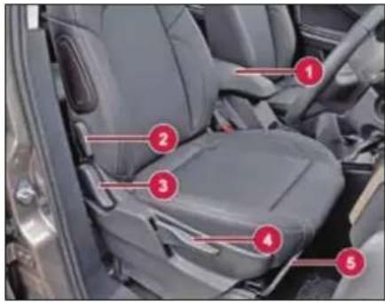
- Arm rest.
- Lumbar support
- Backrest angle
- Seat height adjustment
- Seat forward / rearward adjustment lever
WARNING

You could lose control of your vehicle if you try to adjust the driver's seat, head restraint, mirror, steering wheel and fasten the seat belt while driving. There is a risk of an accident.
Seat backrest angle adjustment
To change the seat back rest angle, lean forward slightly and pull up the lever (1). Adjust seat backrest until it reaches desired comfortable position. Make sure that lever returns to its original position and seat is securely latched.
WARNING

Never travel in a moving vehicle with the seat backrest in an excessively reclined position as this can be dangerous. You could slide under the seat belt in a collision.
Seat height adjustment
To raise the seat, pull and continue pumping the lever (2) in the upward direction until the seat is at the desired height.
To lower the seat, pump the lever down-ward until the seat is at desired height.
Seat forward / rearward adjustment
Lift lever (3) and slide the seat forwards or rearwards. Release lever and make sure that seat is securely latched.
NOTE
Adjust the driver seat position in such a way that the driver will be able to operate the controls pedals comfortably.
Lumbar Support (if equipped)
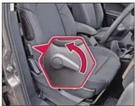
natural_image
Interior view of a car seatbelt with a red arrow indicating clockwise motion (no text or symbols)Continuous (Multiple adjusting position) lumbar support is provided on driver and front passenger seat to give you comfort while driving. It is adjusted by the lever provided on the side of the seat backrest.
Adjustable head restraint (if equipped)
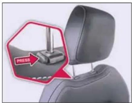
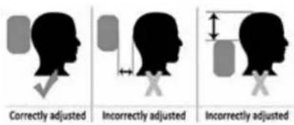
Adjust the head restraint so that it is as close to the head as possible and the center of the head restraint supports the back of the head at eye level. This will reduce the potential for injury to the head and neck in the event of an accident or similar situation.
WARNING

Do not drive the vehicle without the seat head restraints. Head restraints are intended to help reduce injuries during an accident.
Rear seats adjustment
For second row seat adjustment, lift the lever and slide the seat forwards or rearwards. Release the lever and make sure that seat is securely latched.
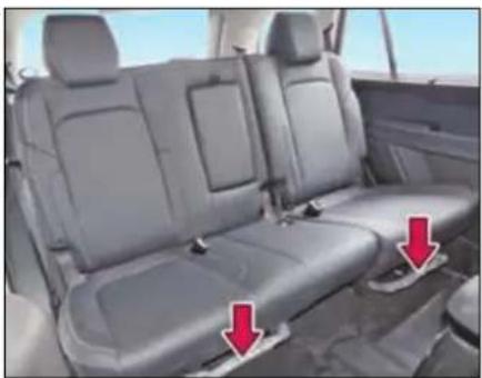
natural_image
Interior view of a car showing two gray leather seats with red arrows pointing to seat covers (no text or symbols visible)Foldable second row (60:40 or captain) seats are provided to access the third row. Refer 'Stowage area' section for seat
STARTING AND DRIVING
folding procedures and access to third row seats.
Third row seats are non-adjustable fixed type seats.
Rear View Mirrors
Inside Rear View Mirrors (IRVM)
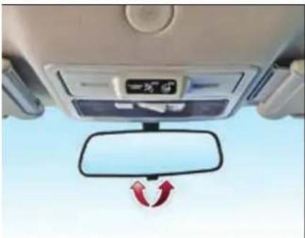
natural_image
Interior view of a car dashboard with a side mirror and directional arrows indicating rotation (no text or symbols)To adjust the mirror, set the selector tab to the normal or antiglare position and then move the mirror up, down or sideways manually to obtain the best rear view.
When driving at night, set the selector tab to select anti-glare mode to reduce glare from vehicles behind you.
NOTE
Use antiglare position only when necessary, as it reduces rear view clarity.
Motorized outer rear view mirrors (ORVM) and power fold (if applicable)
Motorized outer rear view mirrors are fitted on both front doors and can be adjusted to the desired position with the help of a switch provided on the driver side door.
Motorized outer rear view mirrors allow the driver to adjust the mirrors without lowering the glasses and without moving from his position.
You can adjust the mirrors when the ignition switch is in the "ACC" or "ON" position.
NOTE
Objects visible in mirror are actually closer than they appear. Always make sure of the actual distance from the road users traveling behind by glancing over your shoulder.
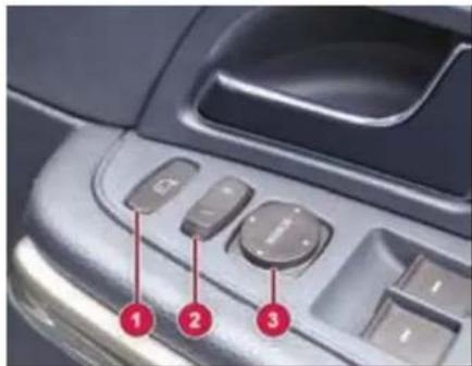
- ORVM fold switch (if applicable)
- Mirror selection switch
- Mirror adjustment switch
To adjust the ORVM:
➢ Move the mirror selection switch to L (for left side) and R (for right side)
Use the 4 positions of the knob to adjust the rear view mirrors to required position.
STARTING AND DRIVING
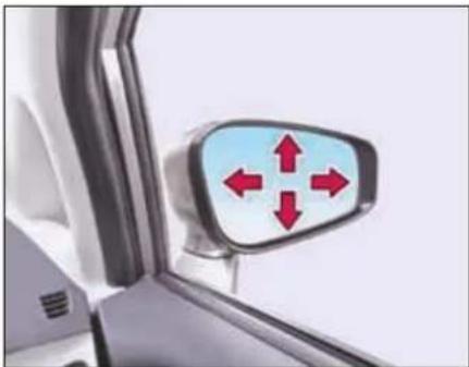
natural_image
Close-up of a car's side mirror with red directional arrows indicating left and right directions (no text or symbols)ORVM folding (if applicable)
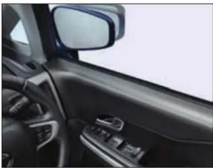
natural_image
Interior view of a car showing the dashboard and side mirror (no text or symbols visible)Outer rear view mirrors can be folded by operating the mirror fold switch (3). This enables you to park your vehicle in limited parking space. Press the mirror fold switch to fold both outside mirrors simultaneously. Press again to unfold.
Demister (if applicable)
These mirrors are provided with demister. For activating the rear view mirror demister and rear windshield demister, a common switch is provided on the A.C. panel.
Sun Visors
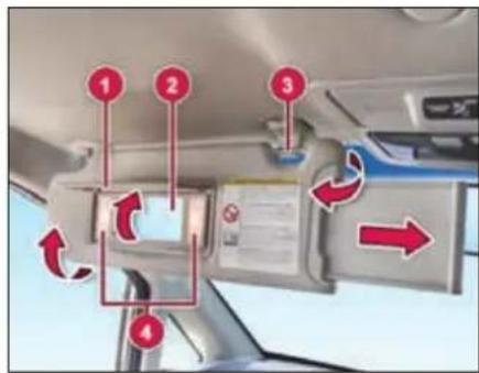
-
Mirror cover
-
Vanity mirror
-
Bracket
-
Mirror light
The sun visors (with extensions) can be pulled down to block glare coming through the windshield.
To block glare from side windows
Pull down the sun visor and release it from the bracket. Swing the sun visor to the side.
Vanity mirror lights (if equipped)
Mirror light (4) only functions if mirror cover (1) has been opened up.
WARNING

If the mirror cover of the vanity mirror is folded up when the vehicle is in motion, you could be blinded by incident light. There is a risk of an accident. Always keep the mirror cover folded down while driving.
STARTING AND DRIVING
Steering Wheel Adjustment
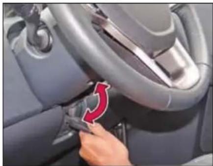
natural_image
Close-up of a car interior showing a hand adjusting the seatbelt with a red arrow indicating rotation (no text or symbols visible)You can adjust the steering wheel position to suit your convenience.
The release lever is located under the steering column.
To adjust the steering wheel
➢ First, adjust the seat to a comfortable position.
➢ Push release lever completely down to unlock the steering column.
Adjust the steering wheel to the desired position.
➢ Pull release lever up completely to lock the steering column.
Make sure that steering wheel is securely locked by checking up and down direction.
NOTE
When adjusting the steering wheel, make sure that:
You can operate control pedals without any obstacles.
You can see all the displays in the instrument cluster clearly.
WARNING

Before starting off, make sure the steering wheel position is locked. Never unlock or adjust the steering wheel while the vehicle is in motion.
Steering lock cum ignition switch
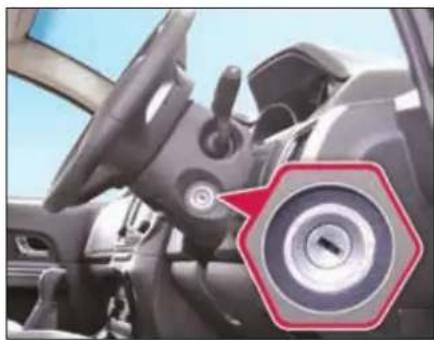
natural_image
Interior view of a car showing steering wheel and dashboard (no visible text or symbols)The ignition switch has the following four positions:
LOCK - This is the normal parking position. Key from lock can be removed in this position only.
"LOCK" position prevents normal use of the steering wheel after the key is removed.
To release the steering lock, insert the key and turn it clockwise to one of the other positions.
ACC - Accessories such as the infotainment system can be operated, but the engine remains 'OFF'. Steering gets unlocked.
ON - This is the normal operating position. All electrical systems are 'ON'.
START - Turn the key further clockwise to the START position, (spring loaded) to start the engine. As soon as the engine starts, release the ignition key, which returns to ON position. While cranking, all accessories will be momentarily 'OFF'.
Illuminated Key Ring
Illuminated key ring is provided on ignition switch. This helps to locate ignition switch in the dark.
Starting the Engine
Make sure that parking brake is engaged and vehicle is in neutral gear (Park Mode for automatic transmission).
Depress the Clutch (Brake pedal for automatic transmission) pedal fully and crank the engine. Do not press the accelerator pedal when starting the engine.
NOTE
The Starter protection system fitted in this vehicle does not allow you to crank the engine until you fully depress the clutch pedal / brake pedal (for AT).
If the engine does not start immediately, hold the ignition key at crank position for approx. 2 secs. This will help to start the engine if starter motor is in fail safe condition operation.
In case of unsuccessful/delayed engine start, kindly contact authorized TATA MOTORS service center.
Starter Protection System
This Starter Protection system provided the following safety conditions:
- Automatic disengagement of starter motor once the engine is started to avoid over running of starter motor.
- Not allowing starter motor to engage when engine is running.
-
No starter motor function when vehicle is in running condition.
-
Not allowing starter motor to crank the engine under low battery condition to avoid further draining if battery.
NOTE
After starting, run the engine in idle speed for at least 30 seconds. Do not press accelerator pedal while starting the engine to avoid damage to turbocharger (in case of diesel vehicles).
Starting off
Manual Transmission
To start off, depress the clutch pedal fully and shift into 1 ^st gear.
After releasing the parking brake, gradually release the clutch and slowly press the accelerator.
Automatic Transmission
To start off, depress the brake pedal fully, press the shift lock button on the knob of the gear selector lever and move the lever to Drive (D) mode.
STARTING AND DRIVING
NOTE
For Automatic variants depress the brake pedal and shift into Drive (D) mode. Release the brake pedal and slowly press the accelerator.
NOTE
When shifting or starting off, do not race the engine. Racing the engine can shorten engine life and affect smooth shifting.
WARNING

Do not switch off the ignition while driving.
If you switch off the ignition while driving, safety-relevant functions are only available with limitations, or not at all. This could affect the power steering and the brake boosting effect. You will require considerably more effort to steer and brake. There is a risk of an accident.
Gear Shifting and Driving Manual Transmission
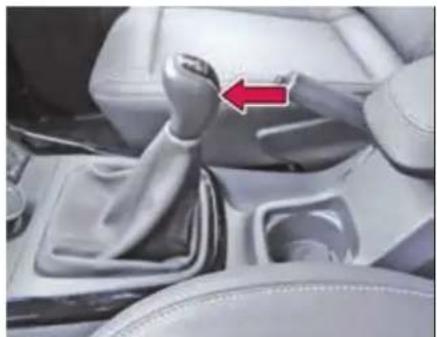
natural_image
Interior view of a car gear shift lever with a red arrow indicating clockwise motion (no text or symbols visible)The gearshift pattern is as shown on the gear lever knob. Gear shifting should always be done with clutch pedal pressed.
NOTE
Depress the clutch pedal fully while shifting the gear. The reverse gear should be engaged only when the vehicle is stationary. Wait for approx. 5 seconds after declutching to ensure smooth engagement of the reverse gear.
Gear indication
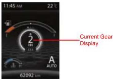
Current Gear number displayed on the DIS screen based on gear shift lever position when clutch pedal is fully released.
NOTE
When there is a failure in the system, instead of gear no 'F' shall be displayed. If 'F' is displayed in the Gear number position, take your vehicle to authorized TATA service centre to get it repaired.
Gear up/down recommender
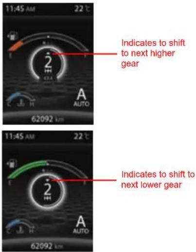
Gear Up/Down recommender shall recommend the user to change the gears for better performance.
NOTE
If the vehicle is in correct gear position, the gear recommender shall not be shown.
Automatic Transmission
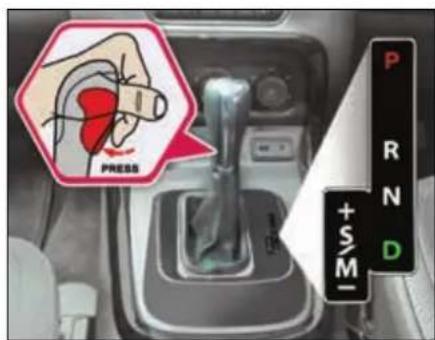
Use Park (P) position when starting the engine or parking the vehicle. Apply the parking brake whenever the vehicle is to be parked.
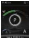
The selector lever must be engaged in Park (P) position only when the vehicle is stationary. If engaged while the vehicle is in motion it may severely damage the transmission.
Reverse (R)
This position puts the transmission in reverse gear when engaged in stationary condition with brake pedal fully pressed.
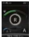
The selector shall never be moved into reverse while driving forward.
Neutral (N)
The transmission is in Neutral position.

It enables the engine to start and operate without driving the vehicle.
Drive Mode (D)
This position is for normal driving conditions for maximum efficiency and fuel economy. It should be used as often as possible.
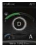
To move the selector to D mode; press the Shift lock button in the handle of the selector lever and at the same time press the brake pedal fully.
STARTING AND DRIVING
Sport / Manual (S/M)
This position allows the driver to switch to Sport mode or activate Manual mode to select gears like a manual gearbox.
Pressing the shift lever towards left side while in Drive mode will put the transmission in Sport mode.
The gear selector moves freely between the Sport (S) and Drive (D) positions. The vehicle will remain in Sport mode if the shifter is not moved at all. As soon as shifter is moved forward or backward, the Manual (M) mode is activated.
It is possible to shift from D mode to Sport or Manual mode and vice versa at any time during driving.
To return to Sport mode after Manual mode has been selected; move the selector lever to Drive mode (by tapping the lever towards right) and then back to Sport mode (by again tapping the lever towards left).
If Manual mode is selected, 1 ^st gear must be used for moving off from stationary condition.
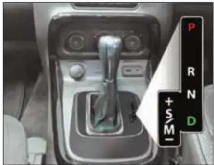
natural_image
Interior view of a car gear shift lever with no visible text or symbols on the component itself‘+’ For Upshifting in Manual mode
Push the gearshift lever to the “+” direction and release it. Every time the lever is operated, upshifting takes place one step at a time in the order of 1^st > 2^nd > 3^rd > 4^th > 5^th > 6^th gear.
‘-’ For Downshifting in Manual mode
Pull the gearshift lever to the “-” direction and release it. Every time the lever is operated, downshifting takes place in the order 6^th > 5^th > 4^th > 3^rd > 2^nd > 1^st gear.
Automatic transmission- manual mode
This Indicates the current gear engaged.
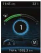
NOTE
• Transmission Control Unit may disallow

incorrect manual shift command by user and a message 'Driver Control Shift denied' is displayed on Instrument Cluster.
- In order to protect the engine, the transmission will automatically upshift to prevent engine over-revving OR downshift to prevent engine stalling at certain specified engine rpm limits.
Drive mode indicator
Auto Mode
This display shows vehicle is in Auto drive mode and background shall be in White in color and 4x4 indicates the vehicle is in four-wheel drive mode.
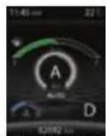
Sport Mode
This display shows vehicle is in Sport mode and the theme shall be in Red color and 4x2 indicates the vehicle is in two-wheel drive mode
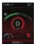
Manual Mode
This display shows vehicle is in Manual mode and the theme shall be in blue color and 4x2 indicates the vehicle is in two-wheel drive mode.
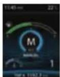
Automatic Gear Shifter Lever Movement and Conditions
| Lever Position Movement | Brake Pedal | Driver Shift | |
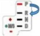 | P->>R | Pressed |  |
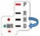 | N->>D | Pressed | Not required |
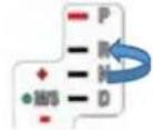 | N->>R | Pressed | 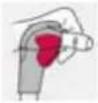 |
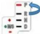 | R->>P | Not required | |

Shifter Lever Knob Pressed
NOTE: For all other conditions no driver intervention required.
STARTING AND DRIVING
Transmission Overheating
If transmission oil temperature increases beyond safe working limit; instrument cluster will display a warning message.
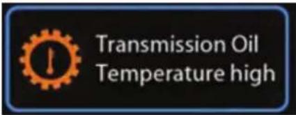
At that time, reduce the vehicle speed and stop the vehicle safely with engine running and transmission in Park mode till the message goes off.
If the problem persists, please contact TATA MOTORS Authorised Service Centre.
Transmission Fault
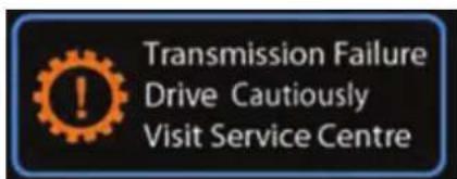
In the event that transmission develops a fault, a warning message will be displayed on instrument cluster.
Please drive cautiously to the nearest TATA MOTORS authorized service centre or if unable to drive call Customer Support for help.
In some events of fault, only limited gears may become available for use and a warning message will be displayed in the instrument cluster.
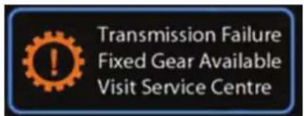
Please visit TATA MOTORS Authorised Service Centre for help.
- Always select Park mode and switch off the ignition before leaving the vehicle.
- Never select a forward gear while the vehicle is in rearward motion.
- Do not rev the engine or allow it to run above normal idle speed, while selecting D or R or whilst the vehicle is stationary with any gear selected.
WARNING

Do not allow the vehicle to remain stationary for any length of time, with selector lever in Drive/Sport/Manual mode and engine running. Always select Park or Neutral if the engine is to remain idle for a prolonged period.
Braking
The distance needed to bring the vehicle to a halt increases with the speed of the vehicle. Start applying brake anticipating the distance and slow down gradually.
WARNING

Never use the brake pedal as a foot-rest.
If you rest your foot on the brake pedal while driving, the braking system can overheat. This increases the stopping distance and can even cause the braking system to fail. There is a risk of an accident.
Never depress the brake pedal and the accelerator pedal at the same time.
If you have driven for a long time in heavy rain without braking, there may be a delayed reaction from the brakes when braking for the first time. This may also occur after the vehicle has been washed.
If brakes are wet, brake performance may become poor and unpredictable.
After driving through water or washing the underside of the vehicle, test the brakes while driving at a slow speed to see if they have maintained their normal effectiveness. If the brakes are less effective than normal, dry them by repeatedly applying the brakes while driving slowly until the brakes have regained their normal effectiveness.
Braking on downhill gradients
On long and steep gradients, you must reduce the load on the brakes by shifting early to a lower gear. This allows you to take advantage of the engine braking effect and helps avoid overheating and excessive wear of the brakes.
NOTE
Use Hill Descent Control (if equipped) function for effective braking on downhill gradients.
WARNING

Do not shift to lower gear on a slippery road surface in an attempt to increase the engine's braking effect, the drive wheels could lose their grip. There is an increased danger of skidding and accidents.
Switching OFF the engine
Turn the key to 'ACC' position to switch off the engine. Before switching off the engine, run the engine in idle condition for at least 30 seconds and then switch off. This will allow the engine oil to lubricate the turbocharger, till its speed is fully reduced and also allow the unit to cool down.
WARNING

A quick burst on the accelerator before turning off the engine serves absolutely no practical purpose, it wastes fuel and is damaging especially to turbocharged engine.
STARTING AND DRIVING
WARNING

When engine is running at high speed do not switch it off. This will lead to premature turbocharger bearing wear.
Parking Brake
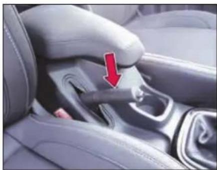
natural_image
Close-up of a car seatbelt buckle with a red arrow pointing to the side panel (no text or symbols visible)Parking brake lever is provided between the driver and co-driver seat on the floor console.
Applying parking brake
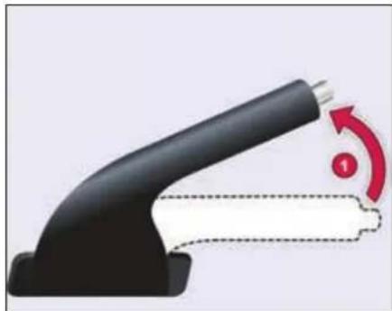
natural_image
Close-up of a black handheld device with a red circular arrow indicating rotation (no text or symbols)To apply the parking brake, pull the lever (1) up fully. The parking brakes tell-tale illuminates on the instrument cluster.
Releasing parking brake
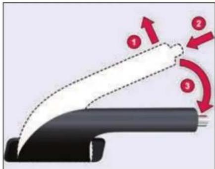
To release it, pull the lever up slightly (1), press the release button (2) and push the lever down (3). Parking brakes tell-tale on the instrument cluster will turn 'OFF' when the lever is fully released.
WARNING

If the parking brake has not been fully released when driving, the parking brake can:
• Overheat and cause a fire
- Lose its hold function.
There is a risk of fire and an accident. Release the parking brake fully before driving off.
WARNING

For Automatic Transmission,
Always keep the gear shift lever in Park Mode and apply the parking brake properly before leaving the vehicle. Use the Park mode along with Parking brake for holding the vehicle on a gradient.
NOTE
Apply the parking brake properly before leaving the vehicle and release it before moving.
Vehicle parking
- Park the vehicle in a safe place. Switch on the indicator signal before turning to park.
- Apply the parking brake.
- Ensure that all window glasses are closed and all lamps are turned off.
- Remove the key from the ignition switch and lock the vehicle.
- Block the wheel if parked on a slope.
NOTE
When parking on a downhill gradient, place the gear lever in 'Reverse' position. While parking on uphill gradient, place the gear lever in the '1 ^st position.
NOTE
Do not use parking brake for braking unless unavoidable circumstances like when service brake is not working properly. The braking distance is considerably longer and the wheels could lock. There is an increased danger of skidding and accidents.
WARNING

Always secure the vehicle correctly against rolling away. Otherwise, the vehicle or its drivetrain could be damaged.
WARNING

Never leave children unsupervised in the parked vehicle. They could also operate the vehicle's equipment. There is a risk of an accident and injury.
DRIVER ASSIST
07
DRIVER ASSIST
Electronic Stability Program (ESP) (if equipped)
ESP monitors driving stability and traction.
If ESP detects that the vehicle is deviating from the direction desired by the driver, one or more wheels are braked to stabilize the vehicle. The engine output is also modified to keep the vehicle on the desired course within physical limits. ESP assists the driver when pulling away on wet or slippery roads. ESP can also stabilize the vehicle during braking.
ESP Operation
During ESP intervention the following actions may occur;
- ESP indicator starts flashing.
- A slight noise from ESP / ABS modulator may be heard, which is only the effect of brake control and indicates nothing unusual.
- Engine may not respond to accelerator in the usual way.
• Cruise control setting gets disabled.
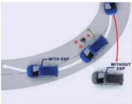
WARNING
ESP is just a driving aid; it cannot enhance your vehicle's stability in all conditions and does not control your vehicle's entire braking system. It is still your responsibility to drive and corner at reasonable speeds and leave a sufficient margin of safety. Always use precautionary measures for safe driving by slowing down on curved, snowy or icy roads.
ESP and tyre sizes
If you drive your vehicle with a non-specified tyres or wheel sizes, the ESP system may not work properly. When replacing tyres, always ensure to use only recommended tyre sizes.
WARNING

In case of an ESP system failure the warning lamp will illuminate in instrument cluster. In that case please pullover the vehicle to the side of road and switch off the ignition and restart. If the fault persists, your ESP system may not be working properly, take the vehicle carefully to the nearest TATA MOTORS authorised service centre for repair.
Traction Control System (TCS)
Traction Control System helps limit wheel slip in acceleration on slippery surfaces.
Vehicle Dynamic Control (VDC)
VDC is an electronic control function to improve vehicle driving behavior. The VDC system can help to prevent under and oversteer by reducing engine speed and applying the brakes individually on specific wheels.
Roll over Mitigation (ROM)
Sometimes when the driver tries to avoid suddenly an obstacle or turns through a corner with high speed, the driver may lose the control and the vehicle tends to rollover.
The main feature of the Roll over Mitigation function is the detection of a rollover critical situation and to prevent the vehicle rollover. This is done by active brake interventions on selected wheels, thereby reducing the forces that cause a rollover situation.
Cornering Stability Control (CSC)
'Corner stability Control' supports/ stabilizes vehicle during partial braking on curves by reducing pressure at required inner wheel of the vehicle.
This helps to reduce probability of vehicle over steering during cornering.
Electronic Brake Pre-fill (EBP)
The Electronic Brake Prefill (EBP) function reduces the air gap of the brake pad and the brake disc. The function is triggered after a sudden release of the accelerator pedal due to an unexpected emergency brake situation. By actively pre-filling the brake-system the brake response time is reduced for an upcoming braking. This results in a shorter stopping distance.
Engine Drag Torque Control (EDTC)
While driving if the driver releases the accelerator abruptly or shifts down a gear quickly, the braking effect of the engine may cause the wheels to skid. The Engine Drag Torque Control (EDC) prevents the wheels from locking under the influence of engine braking to maintain directional stability and enhance safety.
Hill Descent Control (HDC)
(if equipped)
While driving down on a hill slope, activate the HDC feature by pressing the switch ▼ provided on the fascia.
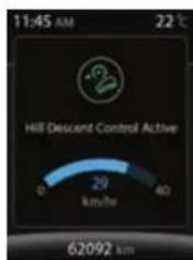
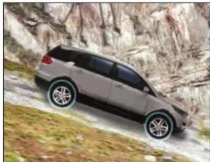
natural_image
Silver SUV driving on a rocky mountain slope, no visible text or symbolsHDC provides a smooth and controlled hill descent by enabling the vehicle to control the speed of each wheel. The system will automatically apply the brakes to slow down to the desired vehicle speed. Cruise control +/-buttons can adjust the speed to a comfortable level. HDC will be automatically disabled once the descent is complete and vehicle is on levelled road. HDC would not be activated if the vehicle speed is above 35 kmph while driving with HDC activated, If the speed goes above 40 kmph, HDC goes into monitoring mode and will get deactivated automatically, once the speed crosses 60 kmph.
DRIVER ASSIST
WARNING

HDC cannot take account of road, weather, traffic and tyre conditions. You are always responsible for keeping control of the vehicle and for assessing whether the downhill gradient can be managed.
Hill Hold Control (HHC) (if equipped)
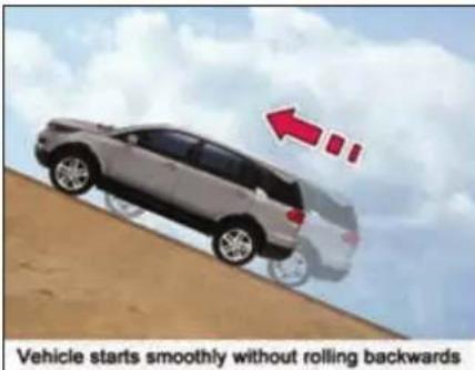
Hill Hold Control allows easy starting up the hill without the risk of unwanted rolling backwards. It is activated automatically when driving off up-hill on an inclined surface after the driver has released the brake pedal.
The braking pressure built-up by the driver during the stop procedure is maintained in the braking system by the HHC function. Braking pressure is released after few seconds. During the pressure hold period, the driver has enough time to press the accelerator pedal to drive off.
The braking pressure is reduced as soon as the system detects the driver's intention to drive off.
WARNING

After a short time, hill hold control will no longer brake your vehicle and it could roll away.
There is a risk of an accident and injury. Therefore, quickly move your foot from the brake pedal to the accelerator pedal.
Torque - On - Demand (TOD) Transfer case (if equipped)
Torque-On-Demand is used for distributing torque between the front and rear axles. According to the driving conditions this system automatically and smoothly delivers two wheel/four-wheel drive operations. In 4 x 4/Auto mode, whenever any slippage is detected in the rear wheels (on icy roads, wet surfaces, etc.) the torque is transferred to the front wheels by the TOD system.
Using TOD system (if equipped)
TOD System provides two operating positions i.e. 4 x 2 Mode and 4 x 4/Auto mode.
To activate 4 x 2 mode, press the 4 x 2 switch provided on

fascia, the LED on the switch turns ON. In this mode, the engine power is supplied to the rear wheels only.
To activate 4 x 4/Auto mode, press 4 x 2 switch again, the LED on the switch turns OFF. In this mode, the engine power is
supplied to both front and rear wheels, based on the driving conditions.
WARNING

While changing over from 4 x 2 to 4 x 4/AUTO mode or vice-versa, make sure the vehicle speed is below 80 kmph.
NOTE
When TOD is in 4 x 4/Auto mode & Ignition switch is in ON position, you will hear a slight noise from the axle connect mechanism. Similarly you will hear same noise while changing over from 4 x 2 to 4 x 4/Auto mode and vice-versa, which is normal.
Activation/Deactivation of TOD in Drive modes
| Drive Mode | TOD (4x4) |
| Auto | ON |
| Comfort | OFF |
| Dynamic | OFF |
| Rough Road | ON |
Cruise Control (if equipped)
Cruise control is meant to reduce driver fatigue, especially when travelling long distances. The cruise control system allows you to program your vehicle to maintain a constant/desired speed without operating the accelerator pedal.
Use cruise control only if road and traffic conditions make it appropriate to maintain a steady speed for a prolonged period.
NOTE
If you fail to adapt suitable driving skill for cruise control, it can neither reduce the risk of an accident nor override the laws of physics. Cruise control cannot take into account the road, traffic and weather conditions. Cruise control is only an aid. You are responsible for the distance to the vehicle in front, for vehicle speed, for braking in good time and for staying in your lane.
Do not use cruise control:
• in road and traffic conditions
which do not allow you to maintain a constant speed e.g. in heavy traffic or on winding roads
- on slippery road surfaces. Braking or accelerating could cause the drive wheels to lose traction and the vehicle could then skid
- when there is poor visibility, e.g. due to fog, heavy rain or snow
If there is a change of drivers, advice the new driver of the speed stored.
Activate Cruise Control only in following gears and speeds
| Gear | Allowable Speed Range (km/h) |
| 1^st | No cruise control |
| 2^nd | No cruise control |
| 3^rd | 30-110 |
| 4^th | 40-150 |
| 5^th | 50-160 |
| 6^th | 60-160 |
DRIVER ASSIST
Cruise Control Switch on Steering Wheel
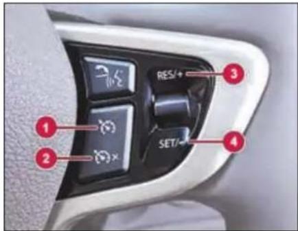
- Cruise control master switch.
- Cruise control deactivating switch.
- Cruise resetting/Speed increasing switch.
- Cruise setting/Speed decreasing switch.
Setting cruise speed
➢ Press the cruise control master switch on steering wheel.
Accelerate the vehicle to the desired speed.
➢ Press the 'SET' button on steering wheel switch to set the desired cruise
speed. The cruise control indicator on instrument cluster will turn 'ON'. Remove your foot from the accelerator pedal.
Once Cruise control is activated the vehicle automatically maintains the stored speed.
Changing the set cruise speed
The set cruise speed can be adjusted (i.e. increased or decreased) using '+' (to increase) or '-' (to decrease) switches on steering wheel. The speed increases and decreases by an interval of 2 kmph on a single press. The changed speed will be shown on the speedometer. Keeping the switch pressed increases or decreases the speed continuously till the switch is released. The set speed can also be increased by pressing the accelerator pedal till the desired speed is achieved and then pressing the 'SET' button. The set speed can also be decreased by pressing the brake pedal (The cruise indicator will turn OFF) and slowing down to desired speed and then pressing the 'SET' button (The cruise control indicator will turn 'ON' again).
NOTE
Cruise control will not be deactivated if you depress the accelerator pedal. For example, if you accelerate briefly to overtake, cruise control adjusts the vehicle's speed to the last speed stored after you have finished overtaking.
Deactivating cruise control
There are several ways to deactivate cruise control:
▶ Applying brake
➢ Press deactivation switch on Steering Wheel
▶ Activation of ESP/ TCS system.
Resuming the set cruise speed
Cruise speed can be resumed only if cruise control is deactivated by depressing Brake Pedal. To resume the previously set cruise speed, accelerate the vehicle to a speed above approx. 32 kmph and press reset ('RES') switch.
WARNING

While travelling on a slope (e.g. hill), Cruise Control may not be able to maintain the SET speed and may be deactivated. Cruise Control can be reactivated using 'SET / RES' switch provided on steering wheel. In such cases use accelerator for increasing speed (when going up) and brakes to decrease (when going down). If brakes are used Cruise Control will be turned off.
Rain & Light Sensor (if equipped)
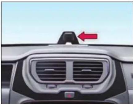
natural_image
Front view of a car dashboard with grille and vent, featuring a red arrow pointing to the top section (no text or symbols visible)WARNING

While cleaning front windshield glass from inside, ensure that solvent should not enter in Rain-Light Sensor otherwise it will be damaged or malfunction.
Auto front wipe (if equipped)
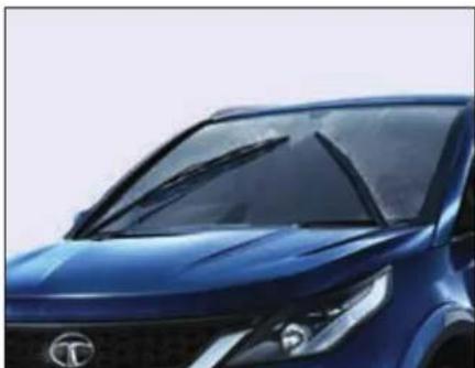
natural_image
Close-up of a blue car front grille with illuminated windows and a logo (no visible text or symbols)The rain sensor automatically operates your vehicle's wipers when it detects raindrops falling on the windscreen. The Auto front wipe gets enabled only when you keep the left wiper stalk in 'AUTO' position and ignition is 'ON'.
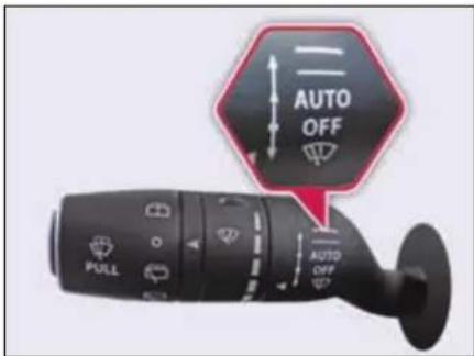
The wiper stalk will also provide five rain sensitivity/frequency settings to allow you to select the sensitivity of the auto wipe system,
The wipe sensitivity can be altered with the help of intermittent wipe rotary switch. P5 is the lowest wiper speed and P1 the highest wiper speed mode.
DRIVER ASSIST
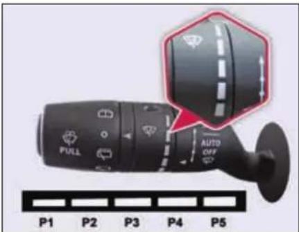
These will vary the amount of rain that must be detected by the rain light sensor before the auto wipe system turns 'ON'. The speed of wiping will be varied depending on the intensity / frequency of rain falling.
NOTE
In case of loss of signal from the Rain and Light sensor, the wipers will sweep in different interval mode as per the sensitivity you select or, till a valid signal is received from the Rain and Light sensor.
Automatic Headlamp mode (if equipped)
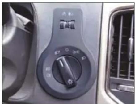
natural_image
Close-up of a car's air conditioner control panel with no visible text or symbols on the dial (pure technical diagram)Automatic Headlamp mode is activated if Master Light switch is in auto mode.
The light sensor automatically switches 'ON' or 'OFF' the head lamps whenever it senses the surrounding light intensity. (e.g. when the vehicle enters a tunnel or when it is twilight).
NOTE
In case of loss of signal from the Rain and Light sensor, the low beam and parking lights will turn 'ON' automatically. Also user can operate manual high beam through combi switch.
WARNING

The automatic headlamp feature is only an aid. The driver is responsible for the vehicle's lighting at all times.
Reverse Park Assist with Camera (if equipped)
Rear View Camera is a visual reverse guiding system, which will guide you while you are reversing.
The rear view camera is only an aid. It is not a replacement for your attention to your immediate surroundings. You are always responsible for safe maneuvering and parking. When maneuvering or parking, make sure that there are no persons, animals or objects in the area in which you are maneuvering.
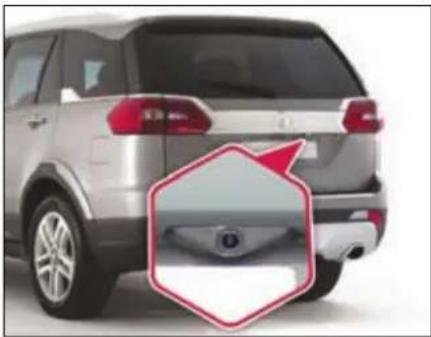
natural_image
Side view of a silver SUV rear bumper with a red hexagonal annotation highlighting the front wheel (no text or symbols on the vehicle itself)WARNING

Make sure that you always reverse the vehicle slowly.
Never reverse while looking only at the display screen. You should always check behind and around the vehicle surroundings while reversing. Always make sure your intended path is clear. If you reverse while looking only at the display screen, you may hit a vehicle, pedestrian, bicyclist, child, pet or other object resulting in injury or death.
Activation
You can activate rear view camera by:
Reverse gear
Park assist feature will automatically start functioning once you engage the reverse gear.
> Infotainment system touch screen
Go to 'Set Up -> Vehicle Setup -> Park Assist -> Enable Park Assist'.
Deactivation
System will deactivate, if reverse gear is disengaged, or park assist button is pressed
Color Guidelines
Guidelines will help you to rightly find the sufficient parking place, helps you to keep the vehicle straight, rear object proximity indication etc.,
Guidelines lengths and widths are just greater than the vehicle length and width respectively. So with the guidelines, you can park the vehicle by checking the sufficiency of the parking place.
DRIVER ASSIST
Understanding Guidelines Indication
Once the rear view camera is activated, you can see, colored guide lines on the screen as shown in the images.
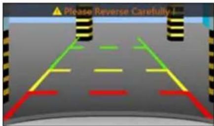
"Static Guidelines - Colored Guide lines are always static"
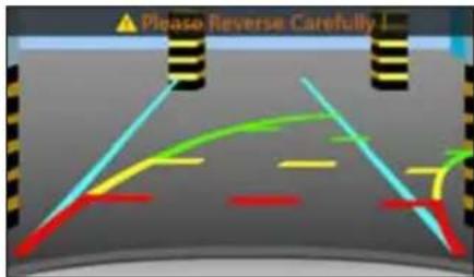
"Dynamic Guidelines - Colored Guide lines will move as per steering wheel rotation (Applicable to ESP variants only).
Cyan line
While reverse parking, Cyan line helps you to identify the sufficient parking place and to align the vehicle straight. Cyan line is a static line.
Green Line
Indicates, if rear object is in this colored zone, you have to be cautious. Still you can go backward safely.
Yellow Line
Indicates, if rear objects are in this colored zone, you have to take utmost care. However, objects fall in this zone, may not hit vehicle.
Red Line
Indicates, if rear objects are in this colored zone, you have to stop the vehicle. And not allowed to go backward. If you still go backward, your vehicle will hit the object.
WARNING

The area displayed by the rear view camera is limited. The camera does not display objects that are close to or below the bumper, underneath the vehicle, or objects out of the camera's field of view. The area displayed on the screen may vary according to vehicle orientation or road conditions.
Using camera
- As the camera is water proof construction, do not detach, disassemble or modify in any manner from the actual position. This will show in correct visual information in display.
- Don't use camera when tailgate is open. If back door is open, visual information may not be the actual rear view of the vehicle.
-
When the camera is operated under fluorescent lights, sodium light or mercury light etc., illuminated areas on the lens may appear to flicker in the display.
-
Do not attach any advertisement or styling or any kind of stickers on top of camera. If this happens, camera cannot provide you the visual image.
- Do not add any accessory, which will obstruct camera field of view.
Cleaning camera
- Due to environmental reasons, dust, mud or fog may accumulate on the camera lens. So regularly clean the camera lens.
- Use water to clean the camera lens. Do not use extreme cold or hot water. Rapid changes in temperature may brittle the camera lens.
- Wipe the camera lens with soft cloth.
- Do not use hard cloth or material to wipe the camera lens. This will cause scratches on the camera, and leads to deteriorated visual image on the display.
-
Do not apply organic solvent, car wax, window cleaner or glass coat to clean the camera. If this is applied, wipe it off as soon as possible.
-
Do not apply heavy force on lens, while cleaning.
- Do not remove mud, snow on the camera lens using stick or hard material. Use normal water and soft cloth.
WARNING

- The camera uses fish eye lens. So the size of the objects or distance from the objects that appear in the display may differ from the actual size and distances.
- In low light conditions, the screen may darken or image may appear faint.
- If the tire sizes are changed, the position of the fixed guidelines displayed on the screen may change.
-
During rainy conditions, image may get obscured. In such conditions, do not depend on camera view.
-
The camera used in the vehicle, may not reproduce the same color of the real object.
- The rear view camera does not display objects that are close to or below the bumper, underneath the vehicle, or objects out of the camera's field of view. The area displayed on the screen may vary according to vehicle orientation or road conditions.
- In case of damage of the rear portion of the vehicle, camera position may change. Which causes wrong visual information on display. In case of damage, make sure that, camera is fitted properly at the intended location.
- In case of uneven road conditions or up-hill or down-hill conditions, do not depend on rear view camera park aid.
- Do not apply any kind of force on the camera.
DRIVER ASSIST
Ultrasonic Reverse Park Assist (if equipped)
Ultrasonic Reverse Park Assist system will assist you to park your vehicle safely when in reverse gear mode. It provides audio and visual information through the vehicles infotainment system.
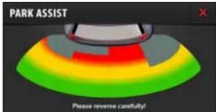
There are 4 ultrasonic sensors placed on the rear bumper of the vehicle. Once the system is activated, the sensors will detect the proximity of an obstacle approximately 0 cm to 150 cm from the bumper, and this information would be displayed on the vehicles infotainment system.
| Distance range from Bumper (in cm) | Visual Info. | Audible Info. |
| 0-50 | Red Zone | Continuous beep |
| 51-100 | Yellow Zone | Fast beep |
| 101-150 | Green Zone | Slow beep |
WARNING

0-25 cm obstacle detection performance is not guaranteed due to ultrasonic sensor technology limitation.
Operation:
Activation- There are 3 ways to activate the reverse park assist.
1. Reverse gear
Park assist feature will automatically start functioning once you engage reverse gear.
2. Reverse Park Assist Switch

By pressing the 'Reverse Park Assist Switch' on the fascia, the feature gets activated. Once activated yellow LED will glow until the feature is deactivated.
LED Indications
a) On start of ignition, if the LED turns 'ON' for a second, then Reverse Park Assist system is healthy.
b) On start of ignition, if the LED turns 'ON' and 'OFF' 10 times, then Reverse Park Assist system is unhealthy. Contact a TATA MOTORS authorised service centre to resolve the problem.
3. Infotainment music system touch display
Go to 'Set Up -> Vehicle Setup -> Park Assist -> Enable Park Assist'.
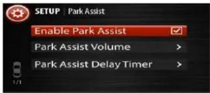
Deactivation:
Following table indicates the deactivation methods of Reverse Park Assist System.
| Deactivated by Activated by | Reverse Gear | Park Assist Button | Music System user interface X button |
| Reverse Gear | √ | √ | √ |
| Park Assist Button | ✕ | √ | √ |
| Music System user interface | ✕ | √ | √ |
NOTE
- Turning the ignition 'OFF' while the Park assist feature is running would disable the feature.
- If reverse gear is already engaged before Ignition 'ON' Park Assist will start automatically after Ignition 'ON'.
Limitations
Reverse Park Assist system is not a collision avoiding system. It is solely the driver's responsibility to park the vehicle safely.
Reverse Park Assist feature works on ultra sound echo technology, due to which performance is not guaranteed in following scenarios:
- If the object has a sharp edge surface, where surface may divert echoes from sensor reception.
- If object is mesh fence made up of thin wires, where echoes can't be given by the surface.
- Fast moving objects passes in the sensor field of detection, where echoes are not processed by the system.
- If object is made/covered by foam or sponge or snow where ultrasonic sound signals are absorbed.
- Sensors covered by mud or external material, by which ultrasonic signals are either not transmitted or received properly.
DRIVER ASSIST
There might be blind spot in Park Assist field of detection close to the rear bumper, where the object has been detected once in any of the zones, may go out of the sensor's field of detection later. In these cases, smaller objects like flower pots, kerb stones, pets or children may not be detected in Yellow or Red warning zones. It's solely driver's responsibility to park the vehicle safely. It is highly recommended to verify through rear/side mirrors of the surroundings before do the reverse parking.
WARNING

Due to any reason, If sensors come out side of bumper or lost its intended fitment position, please contact TATA MOTORS authorised service centre for rectification.
Preventive maintenance
- Regularly clean sensors located on the bumper. Use smooth cloth or material which can't make any scratch on the sensor. Don't apply heavy force while cleaning.
- Do not flush water on sensors with heavy pressure. This will damage sensor.
- Do not apply styling stickers or any material which will stick on the sensors. This will degrade park assist performance.
- Do not fit any objects like foot rest or number plate which will cover the sensor and obstruct its field of detection.
Audio Settings
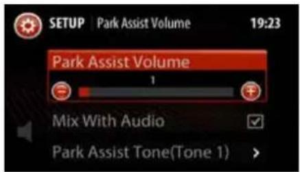
Volume Setting
Go to 'Set Up -> Vehicle Setup -> Park Assist -> Park Assist Volume ->Park Assist Volume'.
Increase or decrease volume by tapping or symbols on the infotainment music system touch screen.
Mix With Audio
By default, Park Assist volume is mixed with infotainment system audio. 'Mix with Audio' option allows you to enjoy music even when park assist is active. With this option, Park Assist warning tone and media tone are smartly mixed together in such a manner that park assist warning tone sounds louder than media tone when park assist is active.
Park Assist Tone
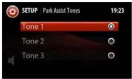
You can select 3 different types of Park Assist tones. To change any tone, you have to follow this sequence of operations,
'Set Up -> Vehicle Setup -> Park Assist -> Park Assist Volume ->Park Assist Volume -> Park Assist Tone'.
Park Assist Delay Timer
If Park Assist system is deactivated by 'Reverse Gear', it will take certain configurable time period to go to previous infotainment screen. This is to ensure that, Pak Assist should not switch off immediately for repeated engagements/disengagements of reverse gear.
You can configure this delay time period by the following sequence of operations,
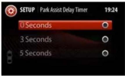
'Set Up -> Vehicle Setup -> Park Assist -> Park Assist Delay Timer'.
Fault Indications
In case of park assist fault or malfunction, following screens may appear on the infotainment music system.
Critical Fault
Reasons for this fault might be
• Park Assist Controller failure
- Sensor malfunction
- Connection loss
DRIVER ASSIST
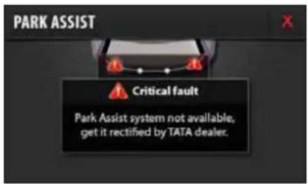
WARNING

If you see above screen on Infotainment music system display, please contact TATA MOTORS authorised service centre for rectification.
Warnings
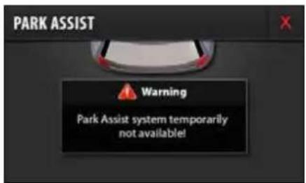
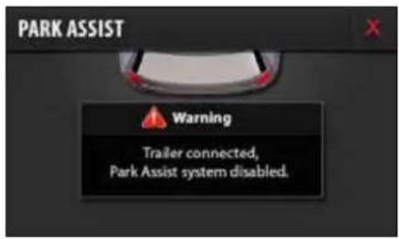
Reasons for this fault might be:
▶ Trailer Connected to the vehicle.
Vehicle speed is too high where Park Assist system can't function
If the system is affected by any surrounding ultrasonic noise.
WARNING

If you see above screens, park assist is malfunctioning due to external conditions. Please rectify as specified on the screen.
DRIVE MODES
08
DRIVE MODES
Drive Modes (if equipped)
Drive Modes is an innovative feature through which user can choose the vehicle dynamics as per driving requirements for comfort and safe drive.
Auto, Comfort, Dynamic and Rough Road mode are provided depending on the vehicle requirements.
NOTE
The Drive mode is only applicable for Manual Transmission.
Drive Mode Selection Switch
A Driver control switch is provided on dashboard fascia for activation.
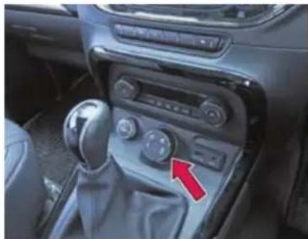
natural_image
Interior view of a car dashboard with steering wheel, mode shift knob, and red arrow indicator (no text or symbols)There are two types of switches available based on the vehicle features and variant.
3 Mode - Auto, Comfort, Rough Road (Vehicle fitted with ABS)
4 Mode - Auto, Comfort, Dynamic and Rough Road (Vehicle fitted with ESP)
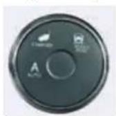
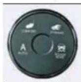
Auto -
It is the default mode. Vehicle will always be in Auto mode whenever ignition is switched 'ON'. Auto Mode is most suitable for highway drive when high performance is desired. This display
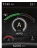
shows vehicle is in Auto drive mode and theme shall be in White in color and 4x4 indicates the vehicle is in four-wheel drive mode.
Comfort -
Rotate the selector knob to Comfort mode. This mode is recommended for city or slow moving traffic conditions as it minimizes
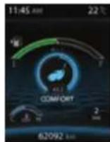
sudden accelerations and helps have better drive control. This also helps to enhance fuel economy. Comfort mode can also be used on highways for a relaxed driving. This display shows vehicle is in Comfort drive mode and theme shall be in
Cyan in color and 4x2 indicates the vehicle is in two-wheel drive mode.
Dynamic - (if equipped) - Rotate the selector knob to Dynamic mode. This mode is more suitable for aggressive and sporty driving style. Enhanced stability control offer to perform extremely safely.
This display shows vehicle is in Dynamic drive mode and theme shall be in Red in color and 4x2 indicates the vehicle is in two-wheel drive mode.
Rough Road - Rotate the selector knob to Rough road mode. It optimizes vehicle behavior for driving over rough road to avoid wheel locking during limited surface contact due to frequent wheel up and down travels. This display shows vehicle is in Rough Road drive mode and theme shall be in Yellow
in color and 4x4 indicates the vehicle is in four-wheel drive mode.
NOTE
- The TOD mode shall be displayed only in XT (4X4) variant.
- If no change in the mode, only Auto mode is observed, take your vehicle to authorized TATA service center.
Drive Mode Functionality
Welcome Strategy
The Welcome strategy shall come for 3 sec. when the Key is inserted and in IGN ON position, All Drive mode LED's shall light up with white colour followed by Amber for 3 sec. After 3 sec. the AUTO mode shall be selected as a default Drive mode in every ignition cycle.
NOTE
Select the Drive mode approximately after 6 sec from the IGN is turned ON as an initialization.
Drive Mode Selection
The default mode in every Ignition ON shall be AUTO mode, User can select the Drive mode by rotating the Drive mode switch in clockwise or anticlockwise.
NOTE
User has to hold the Drive mode switch in desired mode more than 1 sec for proper system behavior on the user selected mode.
DRIVE MODES
1) AUTO to COMFORT mode
When the User is selecting the Drive mode from AUTO to COMFORT, the mode change progress shall be displayed by blinking TOD mode 4X2 in the Instrument cluster and the Drive mode" COMFORT "shall be POP UP for 3 sec. in the center of the display, after 3 sec. the current gear number shall be displayed in the center of the display and Drive mode shall be displayed in the right bottom of the display.
Pop Up for 3 sec
After 3 sec
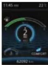
NOTE
When TOD mode (4X4 or 4X2) is blinking on the Instrument Cluster display, the user is not allowed to change the Drive mode. The blinking indicates that the already user selected mode transition in progress.
WARNING

If any failure in the system, all four / three mode shall be illuminated on the Drive control switch and only the AUTO mode is available to user, take your vehicle to TATA authorized service station to get it repaired.
2) AUTO to ROUGH ROAD mode
When the User is selecting the Drive mode from AUTO to ROUGH ROAD mode, the mode change progress shall be completed approximately 1 sec and the Drive mode" ROUGH ROAD "shall be POP UP for 3 sec. in the center of the display, after 3 sec. the current gear no shall be displayed in the center of the display and Drive mode shall be displayed in the right bottom of the display.
Pop Up for 3 sec
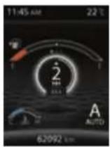
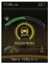
After 3 sec
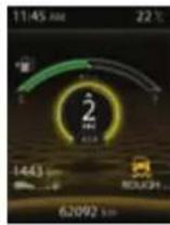
3) COMFORT to DYNAMIC mode
When the User is selecting the Drive mode from COMFORT to DYNAMIC mode, the mode change progress shall be completed approximately 1 sec and the Drive mode "DYNAMIC" shall be POP UP for 3 sec. in the center of the display, after 3 sec the current gear no shall be displayed in the center of the display and Drive mode shall be displayed in the right bottom of the display.
Vehicle applicability: XT (without TOD)
When the user is selecting the Drive mode from AUTO to COMFORT the selected Drive mode shall be POP UP in the Instrument cluster and the Drive mode shall be POP UP for max 3 seconds in the center of the display within approximately after 1 sec, after 3sec the current gear no shall be displayed in the center of the display and Drive mode shall be displayed in the right bottom of the display.
NOTE
The user selected mode shall be illuminated in AMBER color
Drive Control Shift Denied
When drive mode changes in progress and again the user has changed the Drive mode, the following message" Drive Control Shift Denied" shall be displayed in the Instrument cluster for max 3 se shall not be
any change in the Drive mode, the existing user selected drive mode shall be continued.
NOTE
Wait for earlier mode transition to complete to change the drive mode.
DRIVE MODES
Drive Control System Fault
When there is a failure in the system all three/four mode symbols on switch shall be illuminated and the following message "Drive Control System Fault" shall be displayed in the Instrument cluster for 3 seconds.
NOTE
During the failure in the system all the drive modes symbols shall be illuminated in AMBER color, only AUTO mode is available and no selection is possible or allowed during this situation. Take your vehicle to TATA authorized service station to get it repaired.
Drive Control System Display
When you selecting the drive mode the requested drive mode also gets highlighted in the infotainment screen. If you have selected AUTO drive mode through the switch the AUTO drive mode icon would be highlighted on the screen.
AUTO Drive Mode Selected
COMFORT Drive Mode Selected
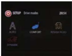
DYNAMIC Drive Mode Selected
ROUGH ROAD Drive Mode Selected
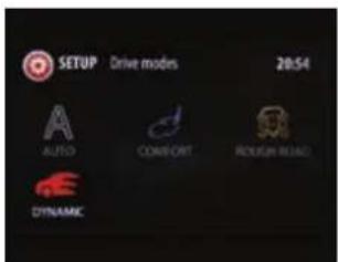
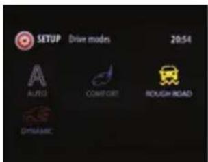
This can be viewed from Head Unit Settings→Drive Modes→option on the infotainment display.
DRIVE MODES
On selecting the drive mode icon on the screen, the help text for the selected mode would be shown as below.
AUTO Drive Mode help text
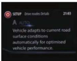
COMFORT Drive Mode help Text
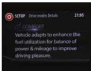
DYNAMIC Drive Mode help Text
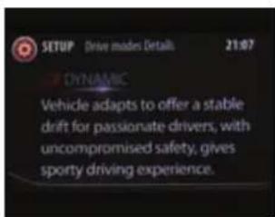
ROUGH ROAD Drive Mode help Text
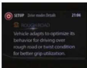
Mood Lighting Display
When you are selecting a drive mode, the driving mode is reflected into the interior lighting as mood lighting. All the interior lighting is predefined for the selected drive mode provided you have selected 'Auto Mode' in Mood lighting'.
Refer "Ambient Mood Lights" for more details.
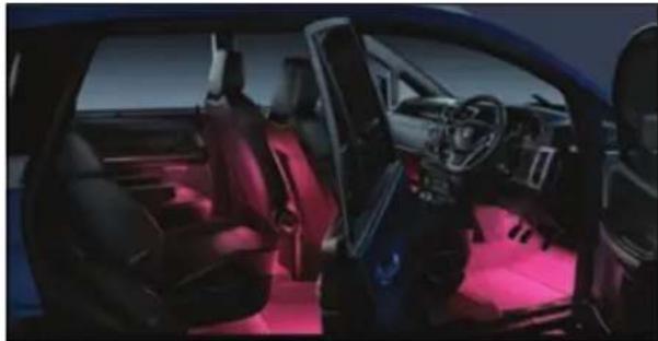
natural_image
Interior view of a modern car with red ambient lighting (no visible text or symbols)The Mood Lighting colors for the selected drive modes are as follows:
| Vehicle Drive Mode | Color in display |
| Auto | White |
| Comfort | Cyan |
| Dynamic | Red |
| Rough Road | Yellow |
NOTE
Interior mood lights would change according to the drive mode selected only if the Mood light settings is set to 'Auto' in Head Unit Screen.
AMBIENT MOOD LIGHTS
09
AMBIENT MOOD LIGHTS
Mood Lighting
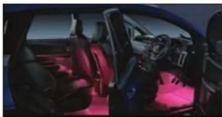
natural_image
Interior view of a modern car with red ambient lighting (no visible text or symbols)Using the Mood lighting feature you can change the color and intensity of your vehicle interior lightening to create or establish a special light effect. This ambient interior lighting also improves the visibility within the vehicle in low lights.
NOTE
Mood light settings can be viewed and modified only when the parking lamp of the vehicle are switched ON.
Mood Light Screen
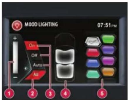
Mood Lighting Screen
1. Intensity selection bar
Increase or decrease the intensity of light color.
2. All
Select all vehicle interior areas in one go.
3. Modes
Select Modes ON/OFF/AUTO ON - Mood lights can be made active with chosen color and intensity (by selecting the desired color out of mentioned colors from mood lighting screen- White, Orange, Red, Purple,
Blue, Cyan, Bluish Green and Fluorescent Green).
NOTE
Area and color zone selections are possible in this mode only.
OFF - Mood lights can be turned OFF.
AUTO - Mood light color changes as per the drive mode selected from drive mode switch. Refer 'Drive Mode' for more details. Color as per selected drive mode will not be displayed on Infotainment screen.
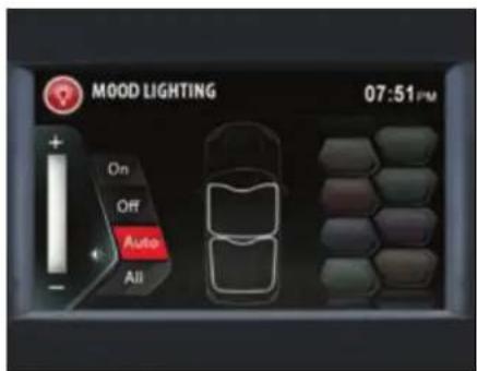
4. Area Selection
Select front or rear area mood lamps as per choice.
5. Color selection
Color palette of 8 colors (White, Orange, Red, Purple, Blue, Cyan, Bluish Green and Fluorescent Green), can be set.
NOTE
Mood Lights turn on in WHITE color (default) whenever roof lamp is made active by removing the ignition key from key barrel and opening any door.
For information on mood lighting features and settings refer infotainment manual.
Activation of Mood Lighting
Mood Lights can be activated from infotainment system by following ways:
Option:1
Go to 'Home -> Setup->Vehicle -> Mood Lighting
- In IGN "ON" position, Home screen will be displayed on Infotainment.
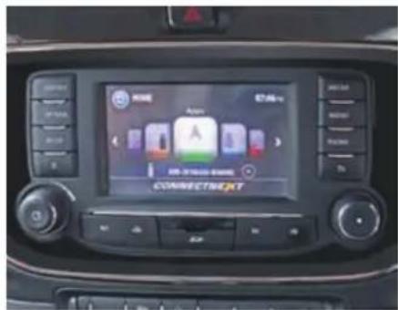
- Press the button. The system displays the "Setup" menu screen with options.
- Select and activate the "Vehicle" option.
- Scroll and select "Mood Lighting" option.
AMBIENT MOOD LIGHTS
- If the parking lamp is in "OFF" position following message will be displayed on the screen. Switch "ON" the parking lamp to activate Mood lighting.
- The system displays the mood Lighting screen when parking lamp is ON.
Option:2
Go to Home screen -> Mood Lighting
- In IGN "ON" position, Home screen will be displayed on Infotainment.
- Scroll horizontally and select the Mood Lighting option.
- If the parking lamp is in "OFF" position following message will be displayed on the screen. Switch "ON" the parking lamp to activate Mood lighting.
- The system displays the mood lighting screen when parking lamp is ON.
Selecting Color
- In the Mood Lightening screen, press the "ON" mode to activate all color palette.
- Touch and select the desired color.
- Increase/decrease the intensity, if required.
Selecting Area
- Mood lights when operated in 'ON' mode can be made ON/OFF as per Front zone/rear zone as per choice.
- When 'All' mode is selected, both front and rear zone will be ON.
NOTE
If the selected color must be set to all areas, click the ALL button.
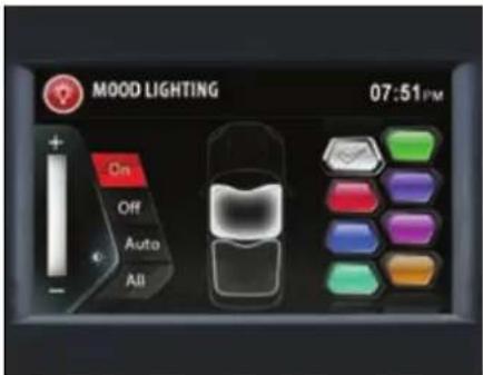
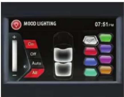
AMBIENT MOOD LIGHTS
Switching Off Mood Lighting
In the mood lighting screen, select the OFF button. All mood lightning related options in the screen are disabled.
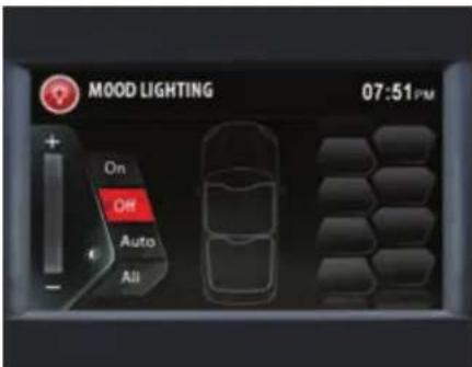
Ambient Mood Lights (Entry/Exit)
Mood Lights turn on in default WHITE color whenever roof lamp made active by removing the ignition key from key barrel and opening any door.
However, with Ignition Key Out both front and rear zone Mood Lights turn on but in case of door open only respective zone LEDs turn ON.
Once the opened door is closed, the Mood lights dims off after approximately 25 sec.
If door is left open, Mood lights will turn OFF after set battery saver time.
EMERGENCY AND BREAKDOWN ASSISTANCE
10
EMERGENCY AND BREAKDOWN ASSISTANCE
Emergency Equipments
You should be familiar with the location of the emergency equipments provided in the vehicle and how to use it.
Check these equipments periodically and ensure that they are in proper working condition and stowed at their locations.
First aid kit
The first aid kit is kept inside the glove box.
The kit contains items that can be used in case of minor injuries only.
NOTE
Check contents of the first aid kit periodically and replenish consumed or expired items.
Advance warning triangle
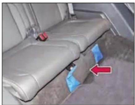
natural_image
Interior view of a vehicle seat assembly with blue trim and red arrow indicating direction (no text or symbols)Advance warning triangle is kept below the 3^rd row seat.
Use advance warning triangle to warn the approaching traffic in case of vehicle break-down or during emergency, where your vehicle could become a potential traffic hazard.
Press hazard warning switch, all turn signal lamps will start blinking.
Keep the warning triangle at an approximate distance of 50-150m behind your vehicle in the same lane of traffic.
The reflecting side of the triangle should face the oncoming traffic and it should be free from any obstacles.
Remove the advance warning triangle carefully from the bag and assemble. Refer instructions given on the bag.
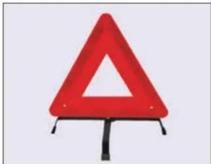
natural_image
Red triangular warning sign with a white triangle symbol, mounted on a black stand (no text or numbers visible)NOTE
After using the warning triangle tie it firmly and keep it inside the bag to avoid rattling noise.
EMERGENCY AND BREAKDOWN ASSISTANCE
Tool kit
Open the tail gate and lift the lid of the storage box to access the tool kit. Notch is provided on lid for convenient lifting.
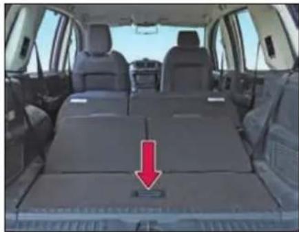
natural_image
Interior view of a car showing rear seats and seatbelt, with a red arrow pointing to the lower side of the seat (no text or symbols visible)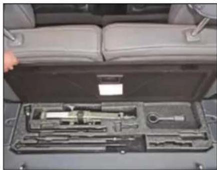
natural_image
Interior view of a car showing a tool kit with handlebars and a hand holding the seat (no visible text or symbols)Tools are provided with your vehicle:
- Jack
- Jack handle
- Wheel spanner
- Tow hook
- Reversible screw driver
- Extension rod for spare wheel removal
NOTE
The tool kit items should be properly stored/secured when not in use.
Hazard warning switch
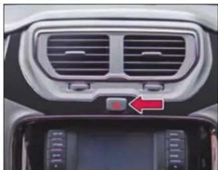
natural_image
Interior view of a car dashboard with ventilation grilles and a red indicator light on the backrest (no text or symbols visible)Press the hazard warning switch to activate the hazard warning. All turn signal
lamps and their tell tales will start flashing simultaneously. To turn it off, press the switch again.
Use the hazard warning to warn the traffic during emergency parking or when your vehicle could otherwise become a traffic hazard.
The hazard warning lamps can operate even if the ignition is switched off.
EMERGENCY AND BREAKDOWN ASSISTANCE
Inertia switch
Inertia switch which will trigger if the vehicle is brought to an abrupt halt, mostly during a collision. Normal driving or sudden braking will not trigger the inertia switch.
When the Inertia switch is triggered:
- All doors will be unlocked.
- All turn indicators will flash.
- All roof lamps will be turned on.
- Fuel supply will be cut off.
To undo the above affects you have to reset the Inertia switch.
Inertia switch is located below glow box on left side of front passenger foot well. It can be accessed through cut out provided on trim.
To Reset the Inertia switch:
➢ Open the front passenger side door and reach out in the area as indicated.
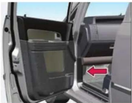
natural_image
Interior view of a car showing the door, vent, and side panel with a red arrow pointing to the door (no text or symbols visible)Access the Inertia switch through cut-out (opening) and press it.
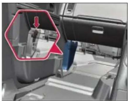
natural_image
Interior view of a vehicle showing a mechanical component with a red arrow pointing to a detail (no text or symbols visible)Inertia switch location
WARNING

After resetting the switch and before resuming driving, check for any damage to the body or check if any part is hanging loose. Also, after turning ON the ignition, ensure that no faults are displayed on the instrument cluster.
In Case of Flat Tyre
- Reduce vehicle speed gradually, without making any sudden steering or braking maneuvers. Pay attention to the traffic conditions as you do so.
- Switch on the hazard warning lamps.
- Stop the vehicle on solid, non-slippery and level ground, as far away as possible from traffic.
- If possible, bring the front wheels into the straight-ahead position.
- Secure vehicle against rolling away.
- Set the parking brake firmly and shift into "R" (Reverse) gear (Manual Transmission) if vehicle is on level ground.
- For automatic transmission, set the parking brake firmly and shift to "P" (Park) mode.
- Switch off the engine.
- Evacuate the occupants from vehicle and locate them at safe place away from traffic.
- Keep advance warning triangle at a suitable distance (50-150m) behind the vehicle to indicate breakdown.
- Close all the doors.
WARNING

If you drive with a flat tyre, there is a risk of the following hazards:
A flat tyre affects the ability to steer or brake the vehicle.
You could lose control of the vehicle. Continued driving with a flat tyre will permanently damage the tyre and cause excessive heat buildup and possibly a fire. There is a risk of an accident.
Spare wheel removal
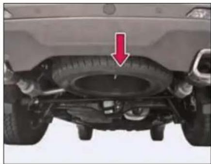
natural_image
Top-down view of a car tire under load, showing tire structure and wheel (no text or symbols visible)➢ Open the tail gate and storage box lid, remove the anti-theft rubber lock.
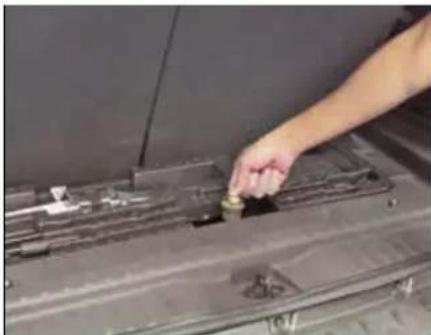
natural_image
Close-up of a hand placing a small object into a dark metal panel (no visible text or symbols)Remove the window cover provided on the rear bumper to access the spare wheel bracket.
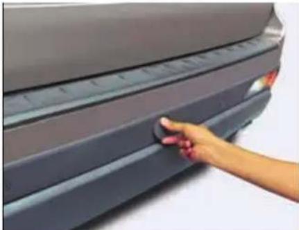
natural_image
Hand pressing down on a car rear bumper area (no visible text or symbols)EMERGENCY AND BREAKDOWN ASSISTANCE
Insert the spare wheel handle with extension through the window.
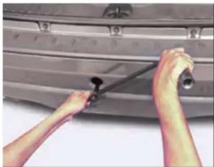
natural_image
Close-up of hands installing or adjusting a car door panel with a tool (no visible text or symbols)Rotate the handle counter-clockwise to lower the spare wheel till it rests on the ground.
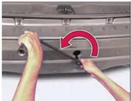
natural_image
Close-up of hands adjusting a car tire with a red curved arrow indicating rotation (no text or symbols)Remove the holding bracket from the spare wheel and get the spare wheel separated.
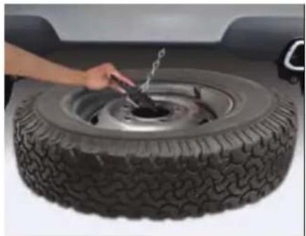
natural_image
Close-up of a hand using a tool to lift a tire, no visible text or symbolsFollowing precautions are to be taken when temporary spare wheel is fitted on the vehicle.
WARNING

- Drive the shortest possible distances. The temporary spare wheel should be exchanged for a normal wheel as soon as possible. The temporary spare wheel is designed for a short period of use only.
- “120 km/h” or “75mph” is the maximum speed you are permitted to drive with this tyre. Never drive faster than 120 km/h (75 mph). Do not accelerate quickly, brake suddenly or drive at high speed through bends.
- After fitting the temporary spare wheel, the tyre pressure must be checked as soon as possible.
- Recommended tyre pressure is 34 psi (2.3 bar) for temporary spare wheel.
- Snow chains cannot be used on the temporary spare wheel.
WARNING

- Never use more than one temporary spare wheel.
- Do not drive through an automatic car wash.
- Never use a temporary spare tyre if it is damaged or worn down to the tread wear indicators.
- The ground clearance of your vehicle may be reduced. Take care when parking next to curb.
- The temporary spare should not be installed on the front axle if the vehicle must be driven in snow or on ice.
- Do not tow whilst the temporary spare wheel is installed.
NOTE
Your vehicle may exhibit some unusual driving characteristics when fitted with temporary spare wheel.
On temporary spare wheel following sticker is provided for identification.
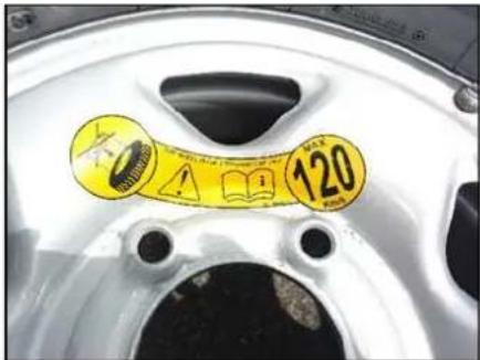
Changing flat tyre
Loosen the nuts (as indicated) on the wheel in cross-wise sequence. Do not unscrew the bolts completely before jacking the vehicle.
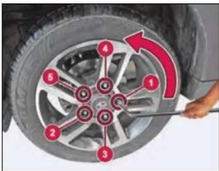
➢ Open the strap and unscrew the wing nuts to take out jack from the tool kit.
Make sure that the jack is placed precisely beneath the jacking point. Position the jack vertically and raise it by turning the jack handle clockwise until the jack sits completely on jacking point and the base of the jack lies evenly on the ground.
EMERGENCY AND BREAKDOWN ASSISTANCE
The jacking points are indicated on the vehicle (Refer jacking point locations).
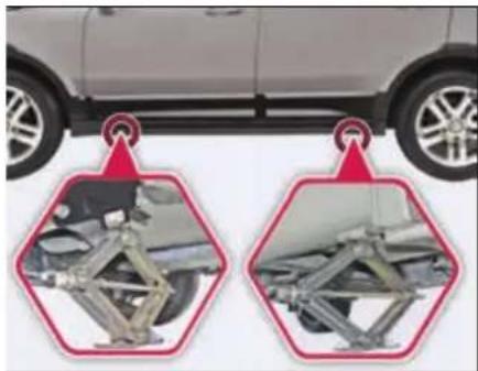
natural_image
Side view of a car with two hexagonal diagrams showing engine suspension components (no text or symbols)Jacking point locations
WARNING

If you do not position the jack correctly at the appropriate jacking point of the vehicle, the jack could tip over with the vehicle raised. There is a risk of injury.
➢ Continue to raise the jack slowly and smoothly until the tyre clears the
ground. Do not raise the vehicle more than necessary.
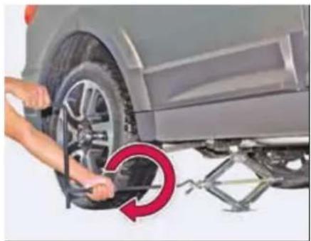
natural_image
Close-up of hands installing a tire on a car wheel, with a red circular arrow indicating the motion direction (no text or symbols visible)Remove wheel-mounting nuts and take out the flat tyre.
NOTE
Do not place wheel nuts in sand or on a dirty surface. Do not apply oil or grease on it.
➢ Roll the spare wheel into position and align the holes in the wheel studs.
➢ Install wheel nuts with their cone shaped end facing the wheel. Tighten
each nut by hand until the wheel is securely seated on the hub.
➢ Lower the jack completely, tighten the wheel nuts one by one in cross-wise sequence using wheel spanner.
WARNING

If you tighten the wheel nuts when the vehicle is raised, the jack could tip over. There is a risk of injury. Only tighten the wheel nuts when the vehicle is on the ground.
WARNING

The wheels could work loose if the wheel nuts are not tightened to the specified tightening torque. There is a risk of accident. Have the tightening torque immediately checked at an authorized workshop after a wheel is changed.
Restore all the tools and jack at their respective location.
Place the flat tyre at spare wheel location.
NOTE
Check and correct the tyre pressure and wheel nuts tightness of the changed wheel at nearest authorised service station.
Get the flat tyre repaired at the earliest.
NOTE
The jack is designed only to raise and hold the vehicle for a short time while a wheel is being changed. It is not suitable for performing maintenance work under the vehicle.
Use the jack on level, hard ground. Avoid changing the wheel on uphill and downhill slopes.
Before raising the vehicle, secure it from rolling away by applying the parking brake.
Do not use wooden blocks or similar objects as a jack underlay.
Never place your hands and feet or lie under the raised vehicle when it is supported by the jack.
Never run the engine when the vehicle is supported by the jack and never allow passengers to remain in the vehicle.
Never open or close a door or the trunk lid when the vehicle is raised.
NOTE
The jack should be used only to change wheels. It is important to read the jacking instructions in this section before attempting to use the jack.
Jump Lead Starting
Use only a battery of same rating & capacity to jump start your vehicle. Position the booster battery close to your vehicle so that the jump leads will reach both batteries.
When using a battery of another vehicle, do not let the vehicles touch.
Apply the parking brake firmly and keep the gearshift lever in neutral.
Turn off all vehicle accessories, except those necessary for safety like hazard warning lamps.
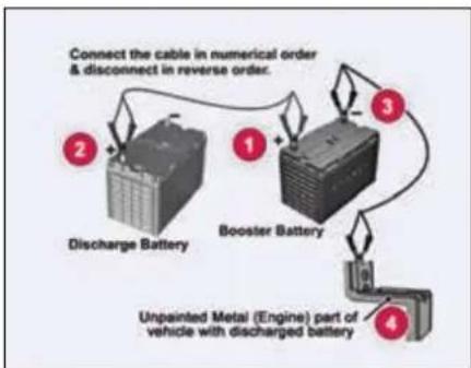
flowchart
graph TD
    A["Discharge Battery"] -->|Connect the cable in numerical order & disconnect in reverse order.| B["Booster Battery"]
    B --> C["Unprevented Metal (Engine) part of vehicle with discharged battery"]
    C --> D["Output"]
EMERGENCY AND BREAKDOWN ASSISTANCE
Make jump lead connections as follows:
➢ Connect one end of the first jump lead to the positive (+) terminal of the discharged battery.
➢ Connect the other end to the positive (+) terminal of the booster battery.
Connect one end of the second jump lead to the negative (−) terminal of the booster battery.
Make the final connection (other end of the negative terminal) to an unpainted, heavy metal part (i.e. engine mounting stud/nut) of the vehicle of discharged battery.
➢ Start the engine of the vehicle with the discharged battery.
Before disconnecting the jumper cables, let the engine run for several minutes.
If the booster battery you are using is fitted to another vehicle, start the engine of the vehicle with the booster battery. Run the engine at moderate speed.
Remove the jump leads in the exact reverse order in which you connected them.
NOTE
Do not disconnect the discharged battery from the vehicle.
WARNING

Never connect the jump lead directly to the negative (−) terminal of the discharged battery. This may lead to an explosion.
WARNING

Do not allow battery electrolyte to come in contact with eyes, skin, fabrics or painted surfaces. The fluid contains acid which can cause injury and severe damage. Wear protective apparel. Do not inhale any battery gases. Keep children away from batteries. Wash battery acid immediately with water and seek medical attention.
During charging and jump-starting, explosive gases can escape from the
battery. There is a risk of an explosion. Particularly avoid fire, open flames, creating sparks and smoking. Ensure there is sufficient ventilation while charging and jump-starting. Do not lean over the battery.
Make sure that the positive terminal of a connected battery does not come into contact with vehicle parts. Never place metal objects or tools on a battery.
It is important that you observe the described order of the battery terminals when connecting and disconnecting a battery. If you are in doubt, seek assistance from qualified specialist workshop.
Never connect or disconnect the battery terminals while the engine is running.
Towing
When towing the break down vehicle, certain precautions and procedures must be taken to prevent damage to the vehicle and/or components. Failure to use standard towing precautionary measures when lifting or towing a break down vehicle could result in an unsafe operating condition.
To ensure proper towing and to prevent accidental damage to your vehicle, take help of a TATA MOTORS authorized dealer or a commercial tow-truck service.
NOTE
Make sure that the parking brake is released; vehicle in neutral gear position and steering wheel is unlocked. The power steering functions only when engine is running. Hence, during towing the steering efforts will be more.
WARNING

- Never get under your vehicle after it has been lifted by a tow truck.
- For towing a vehicle, the best way is to use a wrecker. Alternatively use a rigid tow bar.
- Switch 'ON' the hazard warning indicators of both the vehicles to warn other road users.
- Limit the speed to 20-30 kmph.
- In case of brake failure, use the parking brake to control the vehicle.
- Only secure the tow rope or tow bar at the towing eyes. Otherwise, the vehicle could be damaged.
When towing, pull away slowly and smoothly. If the tractive power is too high, the vehicles could be damaged.
Installing the Tow hook
➢ Open the tailgate and remove the tow hook from the tool kit.
(For front towing) Open the tow hook cover provided on the front bumper grille by pressing and pulling it.
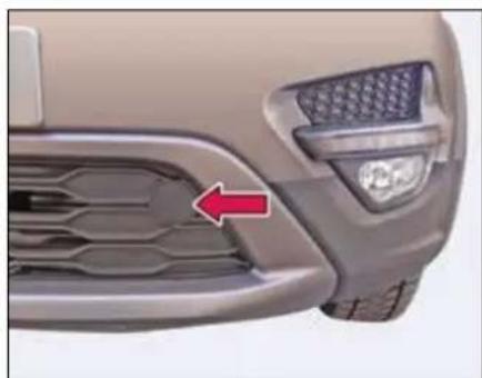
natural_image
Close-up of a car's front grille and headlights (no text or symbols visible)Front tow hook
➢ Engage the tow hook and rotate in clockwise direction to tighten.
➢ After towing, remove the towing hook and fit the cover properly.
➢ Place the towing hook in the vehicle tool kit.
EMERGENCY AND BREAKDOWN ASSISTANCE
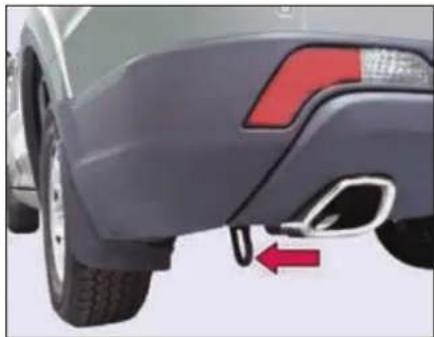
natural_image
Side view of a car's rear bumper and side profile, showing red arrow indicating direction (no text or symbols)Rear tow hook
Recommended towing
We recommend that your vehicle be towed with the driving wheels off the ground or place the vehicle on a flatbed truck as shown.
NOTE
When towing, pull away slowly and smoothly. If the tractive power is too high, the vehicles could be damaged.
WARNING

- Never tow your vehicle with the front wheels on the ground or four wheels on the ground (forward or backward), as this may cause serious damage to the transmission.
- When towing with the rear wheels on the ground or on towing dollies, place the ignition switch in the 'ACC' or 'ON' position, and secure the steering wheel in the straight-ahead position with a rope or similar device.
NOTE
If it is not possible to shift the transmission or start the engine or if the wheels are jammed, the vehicle must be transported on flatbed truck, where the vehicle is loaded into the back of a truck.
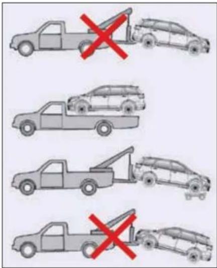
WARNING

Use flatbed tow truck for towing vehicles with 4x4 / Automatic transmission as this may cause serious damage to the transmission.
Fuses
The vehicles electrical circuits have fuses to protect the wiring from short circuits or sustained overload.
Your vehicle has fuse boxes at three locations.
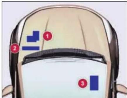
- Engine Compartment Fuse Box
- Battery Mounted Fuse Box
- Cabin Compartment Fuse Box
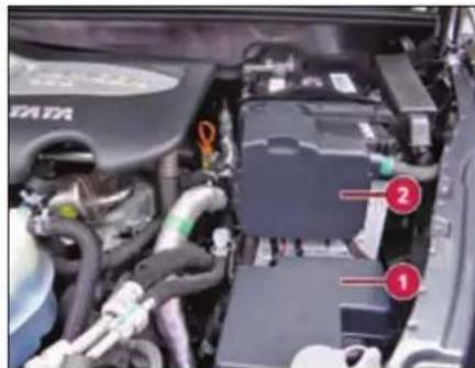
Fuse location- Engine and battery
natural_image
Interior view of a vehicle showing engine, battery pack, and mechanical components (no visible text or symbols)Fuse location- Cabin compartment
Checking and replacing fuses
If any electrical unit in your vehicle is not functioning, check the fuses first.
Please follow the steps below that will guide you to check and replace them.
Apply parking brake
Switch off all electrical consumers.
➢ Turn the ignition key to the 'LOCK' position.
In the fuse box, identify the defective fuse from its melted wire.
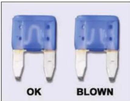
natural_image
Two blue and white electronic component buttons labeled 'OK' and 'BLOWN' (no additional text or symbols visible)Remove the blown fuse by "fuse puller". The fuse puller and spare
EMERGENCY AND BREAKDOWN ASSISTANCE
fuses are provided in the engine compartment fuse box.
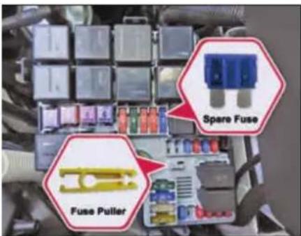
Engine compartment fuse box
➢ Blown fuses must be replaced with fuses of same rating, which you can recognize by color and value.
NOTE
Always ensure that the spare fuses are replenished.
If a newly inserted fuse also blows, have the cause traced and rectified at
a TATA MOTORS authorized service centre immediately.
WARNING

If you manipulate or bridge a faulty fuse or if you replace it with a fuse with a higher amperage, the electric cables could be overloaded. This could result in a fire. There is a risk of an accident and injury.
Always replace faulty fuses with the specified new fuses having the correct amperage.
Battery Mounted Fuse And Relay Box
| Fuse No. | Function | Rating (A) |
| MF1 | STARTER MOTOR | 500A |
| MF2 | ALTERNATOR | 150A |
| MF3 | COCKPIT | 60A |
| MF4 | ABS/ESP | 40A |
| MF5 | IGNITION | 60A |
| MF6 | ||
| MF7 | COOLING FAN 1 | 30A |
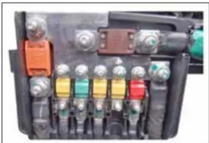
natural_image
Close-up of an automotive electrical switch panel with multiple color-coded buttons and connectors (no visible text or symbols)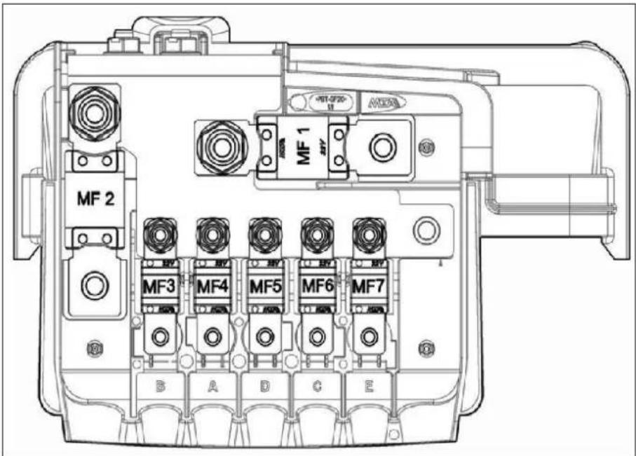
NOTE
The fuse box layouts are provided for reference purpose only. Please refer the sticker provided inside the fuse box cover.
EMERGENCY AND BREAKDOWN ASSISTANCE
- Engine Compartment Fuse and Relay Box
| Fuse No. | Function | Rating (A) |
| F05 | ACCESSORIES | 60A |
| F09 | COOLING FAN II | 40A |
| F10 | HEATED REAR SCREEN | 30A |
| F11 | TOD | 20A |
| F12 | HVAC | 40A |
| F13 | ABS/ESP | 25A |
| F14 | AIRCON | 15A |
| F15 | EMS | 30A |
| F16 | STARTER | 40A |
| F17 | NOT USED | |
| F18 | HEAD LAMP LOW RH | 10A |
| F18A | HEAD LAMP LOW LH | 10A |
| F19 | HEAD LAMP HIGH RH | 10A |
| F19A | HEAD LAMP HIGH LH | 10A |
| F20 | NOT USED | |
| F21 | HORN | 15A |
| F22 | NOT USED | |
| F23 | REAR WIPER | 15A |
| F24 | GLOW PLUG I | 40A |
| F25 | NOT USED | |
| F26 | GLOW PLUG II | 40A |
| F27 | NOT USED | |
| F28 | HAS BATT. | 30A |
| F31 | AFTER MARKET POWER SOCKET | 10A |
| F32 | AT BATT. | 15A |
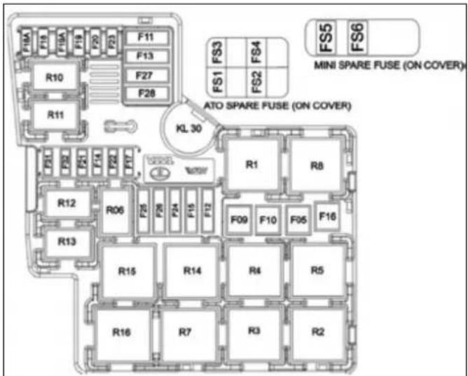
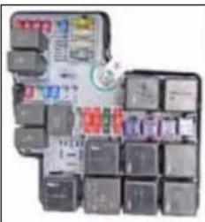
natural_image
Stacked computer keys in a grid layout (no visible text or symbols)NOTE
The fuse box layouts are provided for reference purpose only. Please refer the sticker provided inside the fuse box cover.
EMERGENCY AND BREAKDOWN ASSISTANCE
- Cabin Wiring Harness Fuses & Relay Box
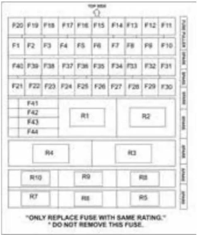
| Fuse No. | Function | Rating (A) |
| F1 | W/W FR LH BATT. | 25A |
| F2 | DRIVE MODE SW BATT | 5A |
| F3 | BCM 1 BATT. | 15A |
| F4 | AFTER MARKET POWER SOCKET BATT. | 10A |
| F5 | CDL BATT. | 20A |
| F6 | DIAGNOSTIC/ BATT. | 5A |
| F7 | HEATED REAR SCREEN (HRW) | 25A |
| F8 | MIRROR HEATER | 10A |
| F9 | - | - |
| F10 | - | - |
| F11 | INSTRUMENT CLUSTER BATT. | 10A |
| F12 | IMMOBILIZER & KEY IN BATT. | 5A |
| F13 | BCM 2 BATT. | 15A |
| F14 | W/W RR RH BATT. | 25A |
| F15 | W/W RR LH BATT. | 25A |
| F16 | TRANSIT / INFOTAINMENT BATT. | 15A |
| F17 | HVAC BATT. | 5A |
| F18 | BCM 3 BATT. | 15A |
| F19 | BRAKE SW BATT. | 5A |
| F20 | W/W FR RH BATT. | 25A |
| F21 | ACC RELAY COIL | 5A |
| F22 | POWER SOCKET III ACC | 15A |
| F23 | USB CHARGER ACC | 5A |
| F24 | RR BLOWER SW IGN | 5A |
| F25 | FR,RR WIPER IGN. | 25A |
EMERGENCY AND BREAKDOWN ASSISTANCE
| Fuse No. | Function | Rating (A) |
| F26 | FR HVAC IGN. | 10A |
| F27 | REVERSE/GSL AT | 5A |
| F28 | PDC,TOD,INT WIPE, DCS IGN | 5A |
| F29 | TOD FR AXLE IGN. | 10A |
| F30 | REV SW/LAMP MT/AT IGN | 5A |
| F31 | SRS (AIRBAG) IGN. | 10A |
| F32 | INSTRUMENT CLUSTER IGN | 10A |
| F33 | ABS / ESP IGN | 5A |
| F34 | EMS IGN | 10A |
| F35 | AT TCU IGN | 5A |
| F36 | IMMOBILIZER IGN | 5A |
| F37 | W/W CONTROLLER IGN | 5A |
| F38 | IGN RELAY COIL | 5A |
| F39 | BCM IGN | 5A |
| F40 | STARTER RELAY COIL | 5A |
| F41 | POWER SOCKET II ACC | 15A |
| F42 | POWER SOCKET I ACC | 15A |
| F43 | REAR BLOWER ACC | 30A |
| F44 | HRW RELAY COIL, HRS COIL, AT ACC | 5A |
NOTE
The fuse box layouts are provided for reference purpose only. Please refer the sticker provided inside the fuse box cover.
Bulbs
Bulbs and lamps are an important aspect of vehicle safety. You must therefore make sure that these function correctly at all times. Have the headlamp settings checked regularly.
Specifications
| Sr. No. | Description | Rating | Type | Qty. |
| 1 | HEAD LAMP HIGH BEAM | 12V/55W | H7 | 2 |
| 2 | HEAD LAMP LOW BEAM | 12V/55W | H7 | 2 |
| 3 | PARKING LAMP FRONT | 12V/5W | W5W | 2 |
| 4 | TURN SIGNAL FRONT | 12V/24W | PY24W | 2 |
| 5 | OUTBOARD STOP LAMP | LED | LED MODULE | 2 |
| 6 | OUTBOARD TAIL LAMP | LED | LED MODULE | 2 |
| 7 | INBOARD STOP LAMP | LED | LED MODULE | 2 |
| 8 | INBOARD TAIL LAMP | LED | LED MODULE | 2 |
| 9 | TURN SIGNAL REAR | 12V/21W | PY21W | 2 |
| 10 | HIGH MOUNTED STOP LAMP | LED | LED MODULE | 1 |
| 11 | REGISTRATION PLATE LAMP | LED | LED MODULE | 1 |
| 12 | DOOR AJAR CUM PUDDLE LAMP | 12V/5W | W5W | 4 |
| 13 | ROOF LAMP FIRST AND SECOND ROW | LED | LED MODULE | 2 |
| 14 | ROOF LAMP THIRD ROW | LED | LED MODULE | 1 |
| 15 | LOAD AREA LAMP | 12V/5W | W5W | 1 |
| 16 | REVERSE LAMP | 12V/21W | P21W | 1 |
| 17 | FRONT FOG LAMP | 12V/35W | H8 | 2 |
EMERGENCY AND BREAKDOWN ASSISTANCE
| Sr. No. | Description | Rating | Type | Qty. |
| 18 | REAR FOG LAMP | 12V/21W | PR21W | 1 |
| 19 | DAYTIME RUNNING LAMPS (DRL) | LED | LED MODULE | 2 |
| 20 | MOOD LIGHTING | LED | LED MODULE | 6 |
| 21 | SIDE REPEATER LAMP ON ORVM | LED | LED MODULE | 2 |
| 22 | GLOVE BOX LAMP | 12V/5W | W5W | 1 |
| 23 | SUN VISOR LAMP | 12V/5W | W5W | 1 |
NOTE
Only install spare bulbs of the same type and the specified voltage.
24 X 7 Road Assistance
Dear Customer,
It is our responsibility and our endeavour to ensure that you have our complete service backup if ever, wherever and whenever you need the same. When you have a road network that spans wide area, the probability of a breakdown happening within hailing distance of a TATA MOTORS Authorized Workshop is very low.
It is precisely for this reason, we have tied up with TVS AA, who will provide breakdown assistance including towing to the nearest TATA MOTORS Authorized Workshop through their Authorized Service Providers (ASP).
The 24X7 On Road Assistance Program shall be automatically available to your vehicle for the duration of Warranty period. The program shall also be available, if you avail the same post warranty.
Response Time ** for the On Road Assistance Program
| Within City Limits | 60 minutes |
| On State or National Highways | 90 minutes |
| Ghat Roads and other places | 120 minutes +/- |
**The response time will depend on the location, terrain, traffic density and the time of the day.)
Standard procedure when calling for On Road Assistance in case of a breakdown:
- Dial the toll free help line number - 1 800 209 7979
- Identify your vehicle with the Vehicle chassis number that is available in the Owner's Manual.
-
Explain your exact location with landmarks and tell us about the problem you face with the vehicle.
-
Park your vehicle on the edge of the road, open the bonnet and put on the hazard warning signal.
- Place the advance warning triangle supplied with the vehicle approx. 3 m from the vehicle in the direction of oncoming traffic.

EMERGENCY AND BREAKDOWN ASSISTANCE
Coverage under 24 X 7 On Road Assistance program
I. The 24x7 On Road Assistance Program Service covers the following services on your vehicle during warranty period.
- Wheel change through spare wheel.
- Arrangement of fuel. (Fuel cost will be chargeable at actual cost)
- Re-opening the vehicle in cases of key lock out.
- Rectification of electrical problems related to battery, fuses etc.
- On spot repairs for complaints repairable at site. ^
- Vehicle to vehicle towing or winching & towing for non-accident cases up to the nearest TATA MOTORS authorized workshop. Towing charges at actual cost beyond the same to be paid to the ASP in cash. (Any ferry or toll charges levied in relation to the vehicle being towed to be paid by the customers in actuals in cash).
For accident cases, towing charges to be borne by the customer.
II. The 24x7 On Road Assistance Program coverage on availing the 24X7 policy, post warranty is upto maximum of 6 instance of assistance in one year for both the plans- Basic and Premium. In the premium plan, this includes 2 instance of towing upto the nearest TATA MOTORS authorised workshop.
Exclusions
24 X 7 On Road Assistance Program does not apply to
- Cost of parts consumables and labour for such repairs not covered under warranty*. These charges are to be settled with ASP in cash.
- Toll or ferry charges paid by ASP in reaching to the breakdown site to be settled with ASP in actuals in cash.
- Cases involving accident, fire, theft, vandalism, riots, lightening, earthquake, windstorm, hail, tsunami, unusual weather conditions, other acts of God, flood, etc.
-
Vehicles that are unattended, un-registered, impounded or abandoned.
-
Breakdown/defects caused by misuse, abuse, negligence, alterations or modifications made to the vehicle.
- Lack of maintenance as per the maintenance schedule as detailed in the owner's manual.
- Cases involving racing, rallies, vehicle testing or practice for such events.
Disclaimer
- **The reach time is indicative & the actual reach time will be conveyed by the call centre at the time of breakdown call.
- The reach time can vary depending on the traffic density & time of the day.
-
The reach time indicated does not account for delays due to but not limited to acts of God, laws, rules & regulations for time being in force, orders of statutory or Govt. authorities, industrial disputes, inclement weather, heavy down pour, floods, storms, natural calamities, road blocks due to accidents, general strife and law & order conditions viz. fire, arson, riots, strikes, terrorist attacks, war etc.
-
^ On spot repairs at breakdown site shall depend on nature of complaints & will be as per the discretion of the ASP.
- *The decision for free of charge repairs will be as per the warranty policy & procedures of TATA MOTORS LTD. and as per the interpretation of the same by ASP. You will be duly informed by the ASP & call centre for the change applicable if any.
- All charges wherever applicable need to be settled directly with the ASP.
Exclusion of Liabilities
- It is understood that TATA MOTORS shall be under no liability whatsoever in respect of any loss or damage arising directly or indirectly out of any delay in or non-delivery of, defect/deficiency in service/parts provided by ASP.
- In case vehicle cannot be repaired on-site, customers are advised to use the towing facility for taking their vehicle to the nearest TATA MOTORS authorized workshop only. In no condition
will the vehicle be towed to any unauthorized workshop. TATA MOTORS will not be responsible for any repairs carried out in such unauthorized workshop.
- Customer are advised to take acknowledgment from the ASP for the list of accessories/extra fittings and other belongings in the vehicle as well as the current condition related to dents/scratches breakages of parts/fitments of the vehicle at the time of ASP taking possession of the vehicle & to verify these items when delivery is taken back by them, Claim for loss of or damage to items, if any should be taken up with ASP directly. TATA MOTORS shall not be responsible for any such claims, damages/loss or any deficiency of service of the ASP.
- Vehicles will be handled, repaired & towed as per the customer's risk & TATA MOTORS shall not be liable for any damages / claims as a result of the same.
- Services entitled to the customers can be refused or cancelled on account of abusive behaviour, fraudulent repre-
sentation, malicious intent and refusal to pay the charges for any charges related services and spare parts during service or on previous occasion on part of the customer.
- On site repairs may be temporary in nature. The completion of repairs does not certify the road worthiness of the vehicle. The customer is advised to ensure temporary repairs carried out onsite is followed by permanent repairs at a TATA MOTORS Authorized Workshop at the earliest.
- Terms and conditions and service coverage, exclusions etc. are subject to change without notice.
MAINTENANCE
11
MAINTENANCE
Maintenance and Service
Periodic maintenance is essential for ensuring long trouble free performance.
Have your vehicle serviced regularly from TATA MOTORS authorized service centre.
There is a large network of TATA MOTORS Authorized Service Center's to help you with their professional servicing expertise. Scheduled maintenance information is provided which makes tracking routine service easy.
The following checks can be carried out between the recommended scheduled maintenance services. Take help of our authorized service centre for assistance.
- Engine oil level
- Engine coolant level
- Brake fluid level
- Washer fluid level
- Battery electrolyte level
• Power steering reservoir - Tyre inflation pressure including spare wheel
NOTE
Refer "Opening and Closing" section for engine bonnet opening.
WARNING

- Be careful not to touch a hot engine, exhaust manifold and pipes, muffler, radiator and water hoses.
- Do not work on a vehicle with the engine running in an enclosed space, unless you are sure you have enough ventilation.
- Keep all open flames and other burning material (such as cigarettes) away from the battery and all fuel related parts.
If you need to do any work inside the engine compartment,
- Switch off the ignition
- Never reach into the area where there is a risk of danger from moving components, such as the fan rotation area
- Keep clothing away from moving parts
Engine Compartment
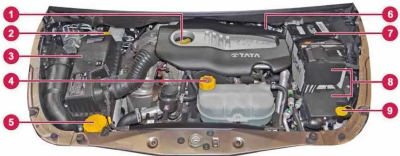
- Engine oil filling cap
- Brake fluid reservoir
-
Air Filter
-
Coolant auxiliary tank
- Power steering reservoir
-
Engine oil Dip stick
-
Battery
- Fuse & relay box
- Windshield washer reservoir
MAINTENANCE
Engine Oil Level
When checking the oil level:
➢ Park the vehicle on a level surface.
Switch off the engine and ensure that engine is at normal operating temperature.
If the engine temperature is high, let the engine cool down before checking oil level. e.g. if the engine was only started briefly, wait for about 30 minutes
WARNING

Certain components in the engine compartment, such as the engine, radiator and parts of the exhaust system, can become very hot. Working in the engine compartment poses a risk of injury.
Where possible, let the engine cool down.
➢ Pull oil dipstick out of the dipstick guide tube.
Wipe off oil dipstick
▶ Slowly slide oil dipstick into the guide tube to the stop, and take it out again.
If the level is between MIN mark and MAX mark the oil level is correct.
If the oil level has dropped to MIN mark or below, top up with recommended engine oil.
NOTE
The oil consumption depends upon the driving style and the conditions under which the vehicle is used.
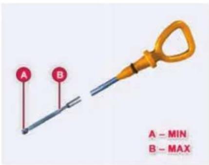
WARNING

If engine oil comes into contact with hot components in the engine compartment, it may ignite. There is a risk of fire and injury.
Make sure that engine oil is not spilled next to the filler neck. Let the engine cool down and thoroughly clean the engine oil off the components before starting the engine.
WARNING

Do not remove the filler cap when the engine is running.
Add oil upto the MAX. mark. Oil levels above the MAX. mark may cause engine damage.
For location of Engine oil filling cap and dip stick, please refer Engine Compartment section.
Brake Fluid Level
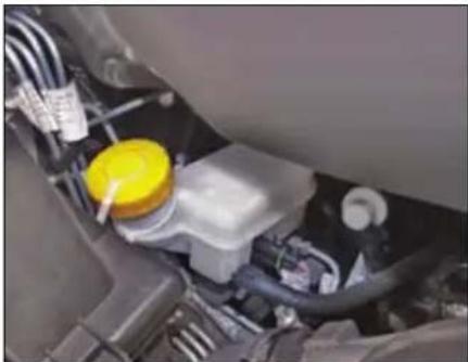
natural_image
Close-up of a car engine bay with yellow plastic container and wiring (no visible text or symbols)The level of the brake fluid should be between the 'MIN' and 'MAX' marks on the side of the brake fluid container. If the level falls below the 'MIN' mark, top up with recommended brake fluid.
For location of Brake Fluid Container and filling cap, please refer respective Engine Compartment section.
WARNING

Do not allow brake fluid to make contact with the skin or eyes.
Do not allow brake fluid to splash or spill on the paint surface as it will damage the paint. In case of spillage, wipe it off immediately.
Engine Coolant Level
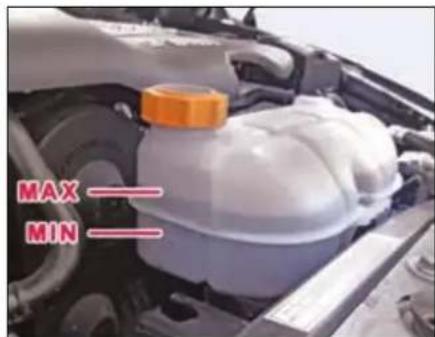
Check the coolant level when the vehicle is on a level surface and the engine has cooled down.
WARNING

The engine cooling system is pressurized, particularly when the engine is warm. When opening the cap, you could be scalded by hot coolant spraying out. There is a risk of injury. Let the engine cool down before opening the cap. Wear eye and hand protection when opening the cap. Open the cap slowly half a turn to allow pressure to escape.
The coolant level should be between the 'MIN' and 'MAX' marks on the auxiliary tank.
When the coolant level is low, top up with recommended coolant through filler of auxiliary tank until the level approaches the 'MAX' level line.
NOTE
In case of emergency, a large amount of water without engine coolant may be added in order to reach a vehicle at service location.
MAINTENANCE
Whenever coolant has been added, the coolant level in the auxiliary tank should be checked the next few times you drive the vehicle to confirm correct level.
For location of Engine coolant container and filler cap, please refer Engine Compartment section.
NOTE
Topping of the coolant should be done in the auxiliary tank only.
Make sure that only TATA MOTORS recommended coolant (Refer 'Technical information' section) is used. Mixing of different coolants may harm your engine's cooling system and its components. Do not add extra inhibitors or additives to the coolant. These can be harmful and compromise the corrosion protection of the engine coolant.
Power Steering Fluid Level
The level of the power steering fluid should be between the MIN. and MAX. marks on the side of the power steering fluid container. If the level falls below the MIN. mark, add recommended fluid. (Refer 'Technical information' section).
WARNING

Do not start the engine without oil in the power steering system. Do not allow dirt into power steering fluid reservoir during refilling or top up.
In case of leakage or hard steering, please contact the nearest Authorised Service outlet.
For location of Power steering fluid container, please refer Engine Compartment section.
Windshield Washer Fluid Level
Check that there is washer fluid in the tank. Refill it if necessary. Use a good quality windshield washer fluid, diluted with water as necessary.
NOTE
Do not use detergent or any other additive in the windshield washer reservoir. This can severely impair visibility when sprayed on the windshield, and can also damage your vehicle's paint.
Do not operate washer motor with no fluid in washer tank, washer motor will be damaged
For location of Windshield Washer filling cap, please refer Engine Compartment section.
Battery
- Check the battery for electrolyte level against the marking on the battery outer case.
- Check the battery terminals for corrosion (a white or yellowish powder). To remove it, cover the terminals with a solution of baking soda. It will bubble up and turn brown.
- When this stops, wash it off with plain water. Dry off the battery with a cloth or paper towel.
- Coat the terminals with petroleum jelly to prevent future corrosion.
- Use a proper wrench to loosen and remove cables from the terminals.
- Always disconnect the negative (-ve) cable first and reconnect it last.
- Clean the battery terminals with a terminal cleaning tool or wire brush.
- Reconnect and tighten the cables, coat the terminals with petroleum jelly.
- Ensure that the battery is securely mounted.
- If you need to connect the battery to a charger, disconnect both cables to prevent damage to the vehicle's electrical system.
For location of battery, please refer Engine Compartment section.
NOTE
During normal operation, the battery generates gas which is explosive in nature. A spark or open flame can cause the battery to explode causing very serious injuries. Keep all sparks, open flames and smoking materials away from the battery.
The battery contains sulphuric acid (electrolyte) which is poisonous and highly corrosive in nature. Getting electrolyte in your eyes or on the skin can cause severe burns. Wear protective clothing and a face shield or have a skilled technician to do the battery maintenance.
Turbocharger
The turbocharger rotor assembly is supported by two fully floating bearing bushes in the bearing housing. These bearing bushes are lubricated with finely filtered engine oil from the lubrication system of the engine.
Lubrication of Turbocharger
Idle the engine for a while (one minute) after starting the engine and before stopping the engine to ensure adequate lubricating oil supply to the turbocharger.
NOTE
Keep engine at idling speed for at least a minute after starting and also before stopping, to protect the turbocharger against damage due to oil starvation.
MAINTENANCE
Intercooler
Hot air coming out of turbocharger flows through the intercooler and gets cooled before entering the intake manifold.
As such it does not require any maintenance however it can be cleaned externally by blowing compressed air.
Transmission Air Oil Cooler
For automatic transmission, hot oil coming out of transmission flows through transmission air oil cooler and gets cooled before entering transmission again.
As such it does not require any maintenance however it can be cleaned externally by blowing compressed air.
WARNING

While cleaning, ensure that inter-cooler and transmission air oil cooler fins are not damaged. If the fins get damaged, it could lead to lose of performance and subsequent failure.
Maintenance recommendations:
- Check the boost pressure pipe for its proper fitment, damage etc.
- Specified engine oil and the oil filter should be used and should be changed regularly in accordance with Service Schedule.
- Check oil feed pipes, return pipes, air intake and exhaust piping for leakages and restrictions.
- Check the engine breathing system and oil separator.
- Fill the oil inlet hole of the turbocharger with clean engine oil, when the engine is started after long storage.
Catalytic Converter
The catalytic converter is fitted on your vehicle to reduce exhaust pollution. The catalytic converter will quickly heat up after starting to ensure that it operates correctly during the warm up phase of the engine.
The catalytic converter does not require any special maintenance however, following precautions should be taken for the effective functioning of the converter and to avoid damage to the converter.
- It is mandatory to use Diesel fuel with low sulphur content (Refer recommended fuels). Use of any other diesel fuel can increase the pollutants.
- Avoid parking the vehicle over inflammable materials, such as dry leaves, grass, etc., as the exhaust system is hot enough to initiate fire.
Maintenance recommendations:
Catalytic Converter should be flushed by giving full throttle (4 to 5 times) in standing condition of vehicle on daily basis. For high speed driving condition run hot for few km as this will help to flush the carbon soot deposits from exhaust system and catalytic converter. High speed running of the vehicle may be done periodically to avoid chocking of catalytic converter.
Alternatively flushing operation for cleaning the catalytic converter can be done by dry compressed air draft (3 to 4 bar) directed on the honeycomb structure of catalytic converter (after removing from vehicle).
WARNING

- Avoid push start or tow-starting the vehicle. (Use jump leads).
- Avoid long (not more than 10 sec.) and repeat (not more than 3 times) starting of the vehicle. Investigate the cause for difficulty in starting & rectify the same.
- Avoid long idling (to warm-up). If the engine is running rough, after a cold start.
- Avoid stopping the vehicle in Drive mode too long with brake pressed since it may overheat and damage transmission. Change to Neutral or Park mode at the earliest.
- Never switch off the ignition when driving down the hill. (This will not save fuel).
- Avoid fuel tank getting almost empty.
- Avoid pre-coating / painting of catalytic converter.
Tyres
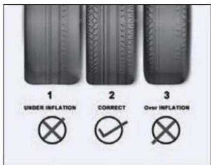
| 1. | Under inflation | Excessive side tread wear |
| 2. | Correct tyre wear | Uniform pressure |
| 3. | Over inflation | Excessive center tread wear |
Inflation
Check for inflation and condition of your vehicle tyres periodically.
Check the pressure in the tyres when they are cold.
Keeping the tyres properly inflated gives you the best combination of riding comfort, handling, tyre life and better fuel efficiency.
Over inflation of tyres makes the vehicle ride bumpy and harsh. Tyres are more prone to uneven wear and damage from road hazards.
Under inflated tyres reduce your comfort in vehicle handling and are prone to failures due to high temperature. They also cause uneven wear and more fuel consumption.
NOTE
Every time you check inflation pressure, you should also examine tyres for damage, trapping of foreign objects in the treads and wear.
MAINTENANCE
Recommended tyre pressures
| Wheels | Tyre Pressure |
| Front | 34 psi (2.3 bar) |
| Rear | 34 psi (2.3 bar) |
Tyre pressure sticker location
The recommended tyre pressure is mentioned as a permissible range in which tyre pressure can be adjusted. The higher value is recommended for getting better fuel economy and lower value is for better ride comfort.
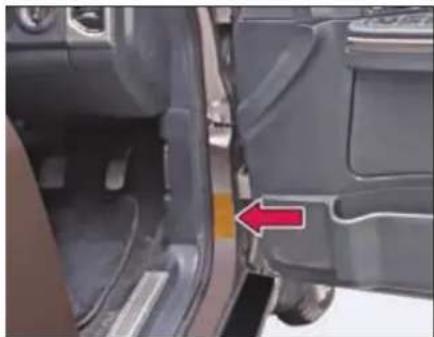
natural_image
Close-up of a car's side profile showing the door and seat, with a red arrow pointing to a specific area (no text or symbols visible)The recommended tyre pressure is mentioned as a permissible range in which tyre pressure can be adjusted. The higher value is recommended for getting better fuel economy and lower value is for better ride comfort.
Regular checking of wheels & tyres
WARNING

Damaged tyres can cause tyre inflation pressure loss. As a result, you could lose control of your vehicle. There is a risk of accident.
Check the tyres regularly for signs of damage and replace any damaged tyres immediately.
Check wheels and tyres for damage at least once a month. Check wheels and tyres after driving off-road or on rough roads. Damaged wheels can cause a loss of tyre pressure. Pay particular attention to damage such as:
• Cuts / Tears in the tyres
- Punctures
- Bulges on tyres
- Deformation or severe corrosion on wheels
Regularly check the tyre tread depth and the condition of the tread across the whole width of the tyre. If necessary, turn the front wheels to full lock in order to inspect the inner side of the tyre surface.
All wheels must have a valve cap to protect the valve against dirt and moisture. Do not mount anything onto the valve other than the standard valve cap.
Regularly check the pressure of all the tyres particularly prior to long trips. Adjust the tyre pressure as necessary.
The service life of tyres depends, among other things, on the following factors:
- driving style
- tyre pressure
- distance covered
- wheel alignment & tyre rotation (at recommended interval)
WARNING

A flat tyre severely impairs the driving, steering and braking characteristics of the vehicle. There is a risk of accident.
NOTE
Life and wear pattern of tyres depends on various parameters like tyre pressure, wheel alignment, wheel balancing, tyre rotation, etc. It also largely depends on vehicle speed, load carried, usage, driving habits, road conditions, tyre quality, etc. to poor quality of tyres, the same may be taken up with concerned tyre manufacturer.
WARNING

If wheels and tyres of the wrong size are used, the wheel brakes or suspension components may be damaged. There is a risk of an accident.
Always replace wheels and tyres with those that fulfill the specifications of the original part.
When replacing wheels, make sure to use the correct specification as recommended.
WARNING

Insufficient tyre tread will reduce tyre traction. The tyre is no longer able to dissipate water. This means that on wet road surfaces, the risk of hydroplaning increases, in particular where speed is not adapted to suit the driving conditions. There is a risk of accident.
If the tyre pressure is too high or too low, tyres may exhibit different levels of wear at different locations on the tyre tread. Thus, you should regularly
check the tread depth and the condition of the tread across the entire width of all tyres.
Special care for tubeless tyres:
- While removing tyre from wheel rim and mounting it back on wheel rim, take precautions not to damage tyre bead. Use tyre removal and assembly machines. Damage or cut on tyre bead may cause gradual loss of air and deflation of tyre.
- Do not scratch inside of tubeless tyre with metallic or sharp object. Tubeless tyres are coated with impermeable layer of rubber from inside which holds the air inside the tyre. Removal of this layer due to scratching may sscause gradual loss of air and deflation.
- If wheel rim gets damaged in service, get the wheel rim repaired/ replaced immediately. Running the vehicle with damaged rim may cause deflation of tyre and subsequent dislodging of tyre from rim.
MAINTENANCE
- Maintain recommended inflation pressure. Over-inflation, in particular, may cause puncture or bursting of tyre.
Tyre rotation
To help increase tyre life and distribute wear more evenly you should have tyres rotated at specified intervals or earlier depending on the operation of vehicle.
Applicable for all tyres Including spare wheel of same size and type
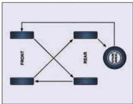
flowchart
graph TD
    A["FRONT"] --> B["REAR"]
    B --> C["VEGET"]
    C --> D["CACT"]
    D --> A
    A --> E["COOL"]
    E --> C
    C --> F["COOL"]
    F --> A
Applicable for vehicle with temporary spare wheel (if equipped)
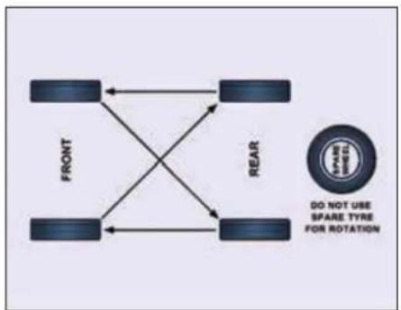
flowchart
graph TD
    FRONT["FRONT"] <--> REAR["REAR"]
    REAR --> FRONT
    FRONT --> REAR
    REAR --> FRONT
    style FRONT fill:#f9f,stroke:#333
    style REAR fill:#bbf,stroke:#333
    note right of REAR: "DO NOT USE SPARE TYRE FOR ROTATION"
Wheel Balancing
Wheels of your vehicle are balanced for better ride comfort and longer tyre life. Balancing needs to be done whenever tyre is removed from rim.
WARNING

If the vehicle vibrates abnormally on a smooth road, have the wheel balanced done immediately.
Wheel Alignment
Incorrect wheel alignment causes excessive and uneven tyre wear. Check wheel alignment at specified intervals. Wheel alignment values are given below:
| Front | Rear | |
| Caster | 3^ ± 30' | - |
| Camber | 0^ ± 30' | - |
| Toe in | 2 - 5 mm | - |
LH to RH variation of Caster to be within 45' LH to RH variation of Camber to be within 30'
Remote Key Battery Replacement
Remote control key contains a battery. It is under the remote cover.
To replace the discharged battery:
▶ Open the key blade.
➢ Press off the battery cover with your thumb or using a flat screw driver at the points of the arrows.
Remove the discharged battery from the key by pressing the battery downwards at the point of the arrow.
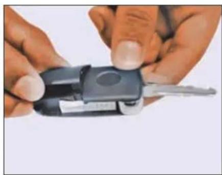
natural_image
Close-up of hands holding a black key with a metallic clip, no visible text or symbolsInsert the new battery.
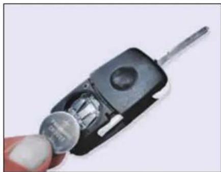
natural_image
Close-up of a hand holding a small metallic object with a screwdriver inserted, next to a black car interior (no visible text or symbols)➢ Ensure that the ‘+’ symbol on the battery is facing upwards. The correct polarity is shown on the battery cover.
➢ Position the battery cover on the key and press on it until it is heard to lock in place.
NOTE
Use CR 2032 battery only.
MAINTENANCE
On Board Diagnostic (OBD II) System
On board Diagnostics or OBD is an automotive term referring to a vehicle's self-diagnostic and reporting capability. The OBD system allows continuous diagnosis of the components of the vehicle correlated with emissions. This system warns the driver, by turning "ON" the Malfunction Indication lamp (MIL) on the instrument cluster, when a fault causes emission levels to increase.
The OBD system also has a diagnostic connector that can be interfaced with appropriate diagnostic tools, which makes it possible to read the fault codes stored in the Electronic Control Unit, together with a series of specific parameters for Engine operation and Diagnosis. This check can also be carried out by the traffic authorities.
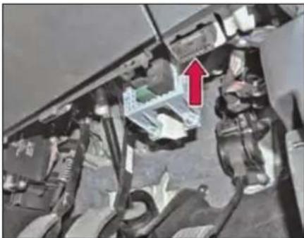
natural_image
Interior view of a vehicle showing engine compartment with a red arrow pointing to a component (no visible text or symbols)SERVICE INSTRUCTIONS
The TATA HEXA has been manufactured to give you economical and trouble free performance. To achieve this please follow the instructions as stated.
Your vehicle is entitled to three free services (labour only). The free service coupons are attached to the sales invoice. Please present these coupons to the servicing dealer while availing free services.
1st free service - At 5000 kms. OR 3, months, whichever is earlier.
2nd free service - At 10000 kms. OR 6 months, whichever is earlier.
3rd free service - At 20000 kms. OR 12 months, whichever is earlier.
All services other than free services are chargeable.
NOTE
Servicing of the vehicle can be done at any TATA MOTORS Authorized Dealer Workshop or TATA MOTORS Authorized Service Centre (TASC).
Warranty claims can be settled by any TATA MOTORS Authorized Dealer Workshop or TATA MOTORS Authorized Service Centre (TASC).
MAINTENANCE
| Sr. No. | Operation | Frequency (Km) | PDI | 5,000-5,500 | 10,000-10,500 | 20,000-20,500 | 30,000-30,500 | 40,000-40,500 | 50,000-50,500 | 60,000-60,500 | 70,000-70,500 | 80,000-80,500 | 90,000-90,500 | 1,00,000-1,00,500 |
| Months | - | 3 | 6 | 12 | 18 | 24 | 30 | 36 | 42 | 48 | 54 | 60 | ||
| General | ||||||||||||||
| 1 | Wash the vehicle & clean the condenser with compressed air. | Every Service | ● | ● | ● | ● | ● | ● | ● | ● | ● | ● | ● | ● |
| 2 | Check & Top up Fluids if required: Engine oil, Coolant, Brake/ Clutch Fluid, Battery Electrolyte, Power Steering Oil, Gear Box Oil, Transfer case (if applicable) & Front Axle 4X4 (if applicable) / Rear Axle Oil | Every 10,000 or 6 Months | ● | ● | ● | ● | ● | ● | ● | ● | ● | ● | ||
| 3 | Drain water accumulated in Fuel Pre filter cum sedimenter and fuel filter (OR whenever the Warning lamp glows) | Every Service | ● | ● | ● | ● | ● | ● | ● | ● | ● | ● | ● | ● |
| 4 | Check engine compartment for loose fasteners and for any leakages in fuel lines, coolant hoses, air hoses, vacuum hoses and hydraulic line connections. Attend if necessary. | Every Service | ● | ● | ● | ● | ● | ● | ● | ● | ● | ● | ● | ● |
MAINTENANCE
| Sr. No. | Operation | Frequency (Km) | PDI | 5,000-5,500 | 10,000-10,500 | 20,000-20,500 | 30,000-30,500 | 40,000-40,500 | 50,000-50,500 | 60,000-60,500 | 70,000-70,500 | 80,000-80,500 | 90,000-90,500 | 1,00,000-1,00,500 |
| Months | - | 3 | 6 | 12 | 18 | 24 | 30 | 36 | 42 | 48 | 54 | 60 | ||
| 5 | Check Underbody for loose fasteners and for any damage or leakage in fuel pipes, hydraulic line connections, rack & pinion & exhaust system including rubber hangers. Attend if necessary. | Every Service | ● | ● | ● | ● | ● | ● | ● | ● | ● | ● | ● | ● |
| 6 | Apply grease on door latches, locks, check straps, strikers, bon-net opening lever, bonnet hinges & lock plate, tailgate hinges & door lock inner ratchet. | Every 10,000 or 6 Months | ● | ● | ● | ● | ● | ● | ● | ● | ● | ● | ||
| 7 | Check for proper tightening of Door latch & Striker screws, Tail gate latch and striker screws | Every 10,000 or 6 Months | ● | ● | ● | ● | ● | ● | ● | ● | ● | ● | ||
| 8 | Check & ensure normal working of the vehicle using diagnostic equipment. | Every Service | ● | ● | ● | ● | ● | ● | ● | ● | ● | ● | ● | ● |
| 9 | Reset the Service interval in In- strument Cluster | Every 10,000 or 6 Months | ● | ● | ● | ● | ● | ● | ● | ● | ● | ● |
MAINTENANCE
| Sr.No. | Operation | Frequency (Km) | PDI | 5,000-5,500 | 10,000-10,500 | 20,000-20,500 | 30,000-30,500 | 40,000-40,500 | 50,000-50,500 | 60,000-60,500 | 70,000-70,500 | 80,000-80,500 | 90,000-90,500 | 1,00,000-1,00,500 |
| Months | - | 3 | 6 | 12 | 18 | 24 | 30 | 36 | 42 | 48 | 54 | 60 | ||
| 2.2L Varicor Engine | ||||||||||||||
| 1 | Replace Engine Oil and Oil filter(Every 20,000 Km OR 1 yearwhichever is earlier) | Every 20Kor 12months | ● | ● | ● | ● | ● | |||||||
| 2 | Replace element / cartridge ofPre-filter cum Sedimenter (Every20,000 Km OR 1 year whicheveris earlier) | Every 20Kor 12months | ● | ● | ● | ● | ● | |||||||
| 3 | Change Main Fuel filter(Every 60,000 Km OR 3 yearswhichever is earlier) | Every 60Kor 36months | ● | |||||||||||
| 4 | Change Air filter element(Every 40,000 Km OR 2 yearswhichever is earlier) | Every 40Kor 24months | ● | ● | ||||||||||
| 5 | Check accessory Drive belts (Al-ternator & Compressor ) adjusttension if required, change ifdamaged (Every 10,000 Km OR 1years whichever is earlier) | Every 10Kor 12months | ● | ● | ● | ● | ● | ● | ● | ● | ● | ● | ||
MAINTENANCE
| Sr.No. | Operation | Frequency (Km) | PDI | 5,000-5,500 | 10,000-10,500 | 20,000-20,500 | 30,000-30,500 | 40,000-40,500 | 50,000-50,500 | 60,000-60,500 | 70,000-70,500 | 80,000-80,500 | 90,000-90,500 | 1,00,000-1,00,500 |
| Months | - | 3 | 6 | 12 | 18 | 24 | 30 | 36 | 42 | 48 | 54 | 60 | ||
| 6 | Replace Timing Belt & Timing Belt tensioner | Every 1,50,000 kms OR 5 years/60 months whichever is earlier | ||||||||||||
| 7 | Change Engine Coolant (Every 60,000 km OR 3 year / 36 months whichever is earlier) | Every 60K or 36 months | • | |||||||||||
| 8 | Check Accessory drive for Power Steering Pump. Change if damaged (Every 10,000 km OR 1 year, whichever is earlier) | Every 10K or 12 months | • | • | • | • | • | • | • | • | • | • | ||
| Gear Box | ||||||||||||||
| 1 | Replace Gear box Oil and Clean Breather (Manual Transmission - if applicable)(First at 40,000 km OR 2 years and thereafter every 90,000 km OR 5 years whichever is earlier ) | Every 90K or 5 Years | • | |||||||||||
| 2 | Clean Breather of 6L550 - Automatic Transmission | Every 10000 or 6 months | • | • | • | • | • | • | • | • | • | • | ||
| 3 | Change Gearbox Oil (6L550 - Automatic Transmission) (If applicable) | Filled for life time | ||||||||||||
| 4 | Change oil in TOD(For 4X4 Only - if applicable) | Filled for life time | ||||||||||||
MAINTENANCE
| Sr.No. | Operation | Frequency (Km) | PDI | 5,000-5,500 | 10,000-10,500 | 20,000-20,500 | 30,000-30,500 | 40,000-40,500 | 50,000-50,500 | 60,000-60,500 | 70,000-70,500 | 80,000-80,500 | 90,000-90,500 | 1,00,000-1,00,500 |
| Months | - | 3 | 6 | 12 | 18 | 24 | 30 | 36 | 42 | 48 | 54 | 60 | ||
| Propeller Shaft | ||||||||||||||
| 1 | Grease propeller shaft with grease gun (at slip joint - splines end) & check Centre bracket mounting bolts for looseness. Tighten if necessary. | Every 10,000 or 6 months | ● | ● | ● | ● | ● | ● | ● | ● | ● | ● | ||
| 2 | Check for rubber cracks on Tor-sional Vibration Damper (TVD), replace if necessary | Every 10,000 or 6 months | ● | ● | ● | ● | ● | ● | ● | ● | ● | ● | ||
| 3 | Change TVD (Every 60,000 km) or 3 Years whichever is earlier | Every 60,000 or 3 Years | ● | |||||||||||
| Front Axle (For 4x4) / Rear Axle | ||||||||||||||
| 1 | Replace Axle Oil ( Front (For 4x4) (if applicable)/ Rear) (Every 80,000 km OR 4 years / 48 months whichever is earlier) | Every 80,000 or 4 Years | ● | |||||||||||
| 2 | Clean Breather in front (for 4x4) (if applicable) and Rear axle | Every 10,000 or 6 months | ● | ● | ● | ● | ● | ● | ● | ● | ● | ● | ||
MAINTENANCE
| Sr.No. | Operation | Frequency (Km) | PDI | 5,000-5,500 | 10,000-10,500 | 20,000-20,500 | 30,000-30,500 | 40,000-40,500 | 50,000-50,500 | 60,000-60,500 | 70,000-70,500 | 80,000-80,500 | 90,000-90,500 | 1,00,000-1,00,500 |
| Months | - | 3 | 6 | 12 | 18 | 24 | 30 | 36 | 42 | 48 | 54 | 60 | ||
| Suspension & Steering | ||||||||||||||
| 1 | Check wheel alignment/ Steering wheel spoke alignment/ wheel balancing & adjust if necessary | Every 20,000 or 12 months | ● | ● | ● | ● | ● | |||||||
| 2 | Check shock absorber and rubber bushes. Replace if necessary (First at 30,000 km and thereafter at every service) | Every Service | ● | ● | ● | ● | ● | ● | ● | ● | ||||
| 3 | Check condition of rubber bushes in Top & Lower wishbones, coil spring rubber seat, Anti roll bars, Rear links, Pan-hard rod, rubber boots/dust cover/ bellow in Rack & pinion, steering ball joints & column, Suspension Ball Joints Replace if necessary. | Every 30,000 or 18 months | ● | ● | ● | |||||||||
| 4 | Replace Power steering Oil & filter element (Every 1,00,000 OR 3 years, whichever is earlier) | Every 1,00,000 or 3 Years | ● | |||||||||||
MAINTENANCE
| Sr.No. | Operation | Frequency (Km) | PDI | 5,000-5,500 | 10,000-10,500 | 20,000-20,500 | 30,000-30,500 | 40,000-40,500 | 50,000-50,500 | 60,000-60,500 | 70,000-70,500 | 80,000-80,500 | 90,000-90,500 | 1,00,000-1,00,500 |
| Months | - | 3 | 6 | 12 | 18 | 24 | 30 | 36 | 42 | 48 | 54 | 60 | ||
| Brakes | ||||||||||||||
| 1 | Check parking brakes, adjust if necessary | Every Service | ● | ● | ● | ● | ● | ● | ● | ● | ● | ● | ● | |
| 2 | Check front brake & rear brake pads, re-grease DIH liner resting points. Replace if necessary. | Every 10,000 or 6 months | ● | ● | ● | ● | ● | ● | ● | ● | ● | ● | ||
| 3 | Replace Brake Fluid (Every 40,000 km or 2 years/24 months which-ever is earlier) | Every 40,000 or 24 months | ● | ● | ||||||||||
| Electricals | ||||||||||||||
| 1 | Check headlamp focusing & functioning of all electrical equipment's | Every 20,000 or 12 months | ● | ● | ● | ● | ● | |||||||
| 2 | Check for looseness of + Ve Terminals on Alternator and Starter motor | Every 30,000 or 18 months | ● | ● | ● | |||||||||
MAINTENANCE
| Sr.No. | Operation | Frequency (Km) | PDI | 5,000-5,500 | 10,000-10,500 | 20,000-20,500 | 30,000-30,500 | 40,000-40,500 | 50,000-50,500 | 60,000-60,500 | 70,000-70,500 | 80,000-80,500 | 90,000-90,500 | 1,00,000-1,00,500 |
| Months | - | 3 | 6 | 12 | 18 | 24 | 30 | 36 | 42 | 48 | 54 | 60 | ||
| AC System | ||||||||||||||
| 1 | Check HVAC System for satisfactory performance, attend if required. | Every Service | ● | ● | ● | ● | ● | ● | ● | ● | ● | ● | ● | ● |
| 2 | Check and Clean A.C Filter | Every 20,000 or 12 months | ● | ● | ● | ● | ● | |||||||
| Wheel & Tyres | ||||||||||||||
| 1 | Tyre Rotation | Every 10,000 or 6 months | ● | ● | ● | ● | ● | ● | ● | ● | ● | ● | ||
MAINTENANCE
Additional Maintenance Schedule under Severe Driving Conditions
| Sr.No. | Operation | Frequency | Condition | |||
| A | B | C | D | |||
| 1 | Engine oil and oil filter | Change every 10,000 kms OR 6 months | ● | ● | ● | ● |
| 2 | Air filter element | Change at every 20,000 km or 18 months whichever is earlier | ● | ● | ||
| 3 | Front (For 4X4) & rear axle oil change | Change at first 20,000 kms (18 months) & thereafter at 50,000 kms (36 months) | ● | ● | ● | |
A - Driving in conditions such as Patrolling, Taxi, Pickup Van, Vehicle Towing, with Trailer Towing
B - Driving on Dusty / Sandy roads
C - Frequently operating in mountainous area
D - More than 50% (in terms of kms) driving in heavy city traffic
NOTE
In case of emergency, a large amount of water without engine coolant may be added in order to reach a vehicle service location.
Vehicle Parking at One Place for Long Duration (Non - Use Maintenance)
If you want to park your vehicle at one place for long duration, following care is to be taken:
- Park the vehicle in covered, dry and if possible well-ventilated premises.
- Remove the battery terminal cables (first remove the cable from the negative terminal).
- Block the wheel or engage in the gear mode.
- Clean and protect the painted parts using protective wax.
- Clean and protect the shiny metal parts using commercially available special compounds.
- Sprinkle talcum powder on the rubber windscreen wiper blades and lift them off the glass.
- Slightly open the windows.
-
Cover the vehicle with a cloth or perforated plastic sheet. Do not use sheets of imperforated plastic as they do not allow moisture on the vehicle body to evaporate.
-
Inflate the tyres to 0.5 bar above the normal specified pressure and check it at regular intervals.
- Check the battery regularly. Change if required.
- Do not drain the engine cooling system.
TECHNICAL INFORMATION
12
TECHNICAL INFORMATION
Fuel Specification
Fuel
High Speed diesel conforming to IS1460 or EN 590 or equivalent is recommended to be used as fuel.
At very low temperature, fluidity of diesel may become insufficient due to paraffin separation. It is therefore necessary to mix supplementary fuel with summer or winter grade diesel. The supplementary fuel to be used is kerosene or aviation turbine fuel.
Ratio for mixing of supplementary fuel and diesel are shown in the table.
| Ambient Temperature in °C | Percentage | |
| Summer grade diesel | Supplementary fuel | |
| Up to 0 | 100 | 0 |
| 0 to -10 | 70 | 30 |
| -10 to -15 | 50 | 50 |
Care should be taken that diesel and supplementary fuel are thoroughly mixed before filling.
| Ambient Temperature in °C | Percentage | |
| Winter grade diesel | Supplementary fuel | |
| Up to -15 | 100 | 0 |
| -15to -20 | 70 | 30 |
| -20and below | 50 | 50 |
WARNING

Do not mix gasoline or alcohol with diesel. This mixture can cause an explosion.
Lubricants
Engine oil: Recommended grade of engine oil confirming to API CI4 Plus, (SAE 15W-40) or higher grade engine oil to be used. Specification and range of ambient temperature at which these can be used are given in the table below:
| Ambient Temp. in °C | Engine Oil Grade |
| -5 and above | SAE 15W40 |
| -10 to 0 | SAE 5W30 |
| -20 to -10 | SAE 0W30 |
Lubricant Specifications
| Item | Specification | Company and Brand | Qty. |
| ENGINE OIL | API CI4 Plus, (SAE 15W-40) | EXXON MOBIL Super Diesel 15W40 CI-4 Plus | 7.5 Litres |
| PETRONAS TATA MOTORS Genuine Oil - Engine Oil CI4+ 15W40 | |||
| HPCL HP Milcy CI4+ Tata Motors Genuine oil | |||
| IOCL Servo Tata Motors Genuine oil CI4 Plus | |||
| COOLANT | 40:60 ratio Premixed | Sunstar Tata Motors Genuine Coolant 2200 | Approx. 9 Litres |
| IOCL Servo Tata Motors Genuine Coolant 4060 | |||
| GEAR BOX G-85 G-76 | Synthetic gear oil 75W90 GL4 | HPCL HP GO XP 75W90 Tata Motors Genuine Oil | G85- 3.25 Litres G76- 2.2 Litres |
| Castrol SYNTRO 75W90 GL4 | |||
| IOCL Servo Tata Motors Genuine Gear Oil - 75W 90 | |||
| EXXON MOBIL MOBILUBE 1 SHC 75 W 90 | |||
| Automatic Transmission (6L50) | ATF DEXRON-VI | EXXON MOBIL IMP 6544 MOBIL DEXRON-VI | Approx. 11.4 Litres |
| TOD | -- | SHELL Spirex S3 ATF MD3 | 1.2 - 1.4 Litres |
TECHNICAL INFORMATION
| Item | Specification | Company and Brand | Qty. |
| POWER STEERING OIL | ATF-DEXRON IID | Castrol ATF DEX III | 1.6 Litres |
| HPCL HP ATF DEX III Tata Motors GENUINE OIL | |||
| IOCL Servo Tata Motors Transdex III | |||
| EXXON MOBIL Mobil ATF 220 | |||
| REAR AXLE(Limited Slip Differential) | 85W140 API-GL5Anglomol 6043 | HPCL HP Gear Oil XP 85W140 Tata Motors Genuine Oil | 1.8 Litres and 0.09 Litres(For friction modifier) |
| CASTROL Extra Long Life Rear Axle Oil 85W140 | |||
| PETRONAS TATA MOTORS Genuine Oil - Axle Oil 85W140 | |||
| IOCL Servo Tata Motors Genuine Axle Oil - 85W 140 | |||
| REAR AXLE(Standard Differential) | 85W140 API-GL5Anglomol 6043 | HPCL HP Gear oil XP 85W140 Tata Motors Genuine Oil | 1.8 Litres |
| CASTROL Extra Long Life Rear Axle Oil 85W140 | |||
| PETRONAS TATA MOTORS Genuine Oil - Axle Oil 85W140 | |||
| IOCL Servo Tata Motors Genuine Axle Oil - 85W 140 |
TECHNICAL INFORMATION
| Item | Specification | Company and Brand | Qty. |
| LIVE FRONT AXLE | 80W90 oil with A 2099 additive | IOCL Servo Gear Axle TM 80W90 | 1.8 Litres |
| BRAKE / CLUTCH FLUID | SAE J 1703, DOT 4 | S-CCI Golden Cruiser Tata Genuine Brake Fluid (DOT4) | As required |
| CASTROL Brake fluid DOT 4 | |||
| Petronas TUTELA Brake Fluid TOP 4 TM |
TECHNICAL INFORMATION
Technical Specifications
| Engine | |
| Model | TATA 2.2L VARICOR |
| Type | Direct injection, Common rail, Turbo-charged, Intercooled Diesel Engine |
| No. Of Cylinders | 4 inline |
| Capacity | 2179 cc |
| Maximum Engine Output | 1) 115 kW (156 Ps) @ 4000 +/- 100 rpm as per CMVR / 115 - (9) 19962) 110 kW (150 Ps) @ 4000 rpm as per CMVR / 115 - (9) 1996 |
| Maximum Torque | 1) 400 Nm @ 1750 - 2500 rpm as per CMVR 115 - (9) 19962) 320 Nm @ 1500 - 3000 rpm as per CMVR 115 -(9) 1996 |
| Transmission | |
| Model | 1) G-6450, 6 Speed with overdrives.2) Auto Transmission 6 speed (6L50)3) GBS-76 -5 speed/ 4.1, MK-II with overdrives |
| Rear Axle | |
| Type | ABS with LSD / ESP without LSD |
| Steering | |
| Type | Rack and Pinion steering with power assistance (Hydraulic). |
| Brakes | |
| Service Brake | Vacuum assisted independent hydraulic brakes on front & rear through tandem master cylinder. Vacuum pump camshaft driven |
| Front Brakes | Ventilated disc brakes with twin pot caliper |
| Rear Brake | Disc brake - single pot caliper with DIH |
| Anti-lock Braking System (ABS) | 4 channel, 4 sensors (For ABS) |
| Electronic Stability Program (ESP) | 4 Channel, 4 Sensors & Other Sensors |
| Parking Brake | Lever type, Console mounted, Cable operated mechanical linkage acting on Rear wheels through DIH. |
TECHNICAL INFORMATION
| Frame | |
| Type | Ladder type cranked frame with Box section members and welded cross members |
| Suspension | |
| Front | Double wishbone type with coil springs over Shock Absorber. |
| Rear | Coil spring type 5 link rigid axle suspension |
| Shock Absorber | Hydraulic double acting telescopic at Front & Rear |
| Anti-roll Bar | At both front & rear |
| Wheels & Tyres | |
| Tyres | Passenger Radial, Tubeless.1) 235/55 R19 (105 T)2) 235/70 R16 (105 S) |
| Wheel Rims | 1) 7.5J X 19 Alloy2) 6.5J X 16 Stylized Steel |
| No. of Wheels | Front: 2 Rear: 2 Spare:1 |
| Fuel Tank | |
| Capacity | 60 Litres |
| Electrical System | |
| System Voltage | 12 Volts (-ve earth) |
| Alternator Capacity | 155 amps |
| Battery | 12V, 75Ah/80Ah 20 Hrs |
| Performance | |
| Max. Speed at rated GVW | 1) 170 kmph2) 180 kmph |
| Grade Restartability (at rated GVW) | 43% |
| Max. gradeability (at rated GVW) | 61% |
| Passenger Capacity | |
| Passenger Capacity | Front Seat: Driver + 1,Middle Seat: 3 (Bench Seat, 60:40) or 2 (Captain Seats)Rear Seat: 2 (Front Facing) |
TECHNICAL INFORMATION
| Weights (Kg) | ||
| Variants | Gross Vehicle Weight (GVW) | Kerb Weight |
| XM 4x2 (7 seater) | 2738 | 2113 |
| XM 4x2 (6 seater) | 2719 | 2094 |
| XT 4x2 (7 seater) | 2806 | 2181 |
| XT 4x2 (6 seater) | 2787 | 2162 |
| XT 4x4 (7 seater) | 2905 | 2280 |
| XT 4x4 (6 seater) | 2886 | 2261 |
| XMA 4x2 (7 Seater) | 2755 | 2130 |
| XMA 4x2 (6 Seater) | 2736 | 2111 |
| XMA 4x4 (7 Seater) | 2855 | 2230 |
| XMA 4x4 (6 Seater) | 2836 | 2211 |
| XTA 4x2 (7 Seater) | 2800 | 2175 |
| XTA 4x2 (6 Seater) | 2781 | 2156 |
| XE 4x2 (7 Seater) | 2738 | 2113 |
| XE 4x2 (6 Seater) | 2719 | 2094 |
| Luggage Space | |
| Net inside loading space | ~ 1000 mm wide x ~ 800 mm long (with 4 passengers + Driver) |
| Main Chassis Dimension as per ISO:612 In mm | |
| Wheel Base | 2850 |
| Track Front | 1) 1590 (with 19" tyres)2) 1580 (with 16" tyres) |
| Track Rear | 1) 1560 (with 19" tyres)2) 1550 (with 16" tyres) |
| Overall Length | 4788 over rear bumper |
| Overall Height | 1785 |
| Max. Width | 1900 |
| Ground Clearance | 1) 209 mm (unladen - with 19" tyres)2) 200 mm (unladen - with 16" tyres) |
Vehicle Dimensions
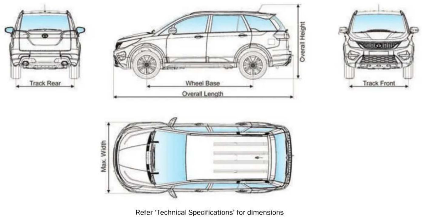
VEHICLE CARE
13
VEHICLE CARE
Vehicle Care
Your vehicle is subjected to many external influences such as climate, road conditions, industrial pollution and proximity to the sea. These conditions demand regular care of the vehicle body. Dirt, insects, bird droppings, oil, grease, fuel and stone chippings should be removed as soon as possible.
Washing
Follow these tips while washing your vehicle.
Hand wash:
- Always wash your vehicle in shade.
- Wash with mild vehicle wash soap like 'Car Shampoo' and use a soft bristle brush, sponge or soft cloth and rinse it frequently while washing to avoid scratches.
- To avoid scratches, please wear soft gloves. Remove finger rings, nails, wrist watch while washing.
- To remove stubborn stains and contaminants like tar, use turpentine or
cleaners like 'Stain remover' which are safe for paint surfaces.
- Avoid substances like petrol, diesel, kerosene, benzene, thinner or other solvents that cause damage to paint.
- Dry your vehicle thoroughly to prevent any damp spots.
- Rinse all surfaces thoroughly to prevent any traces of soap and other cleaners as this may lead to the formation of stains on the painted surface later.
WARNING

Do not direct high pressure washer fluid/ water jets (Pressure above 0.5 Bar) at electrical devices and connector during washing. This is to prevent malfunction / failure of electrical system due to water ingress.
After drying the vehicle, inspect it for chips and scratches that could allow corrosion to start. Apply touch up paint where necessary.
NOTE
Avoid wiping of painted surface in dry condition as it may leave scratches on the painted surface.
Cleaning of Carpets
Vacuum clean the carpet regularly to remove dirt. Dirt will make the carpet wear out faster. Periodically shampoo the carpet to keep it looking new.
Use carpet cleaners (preferably foam type). Follow the instructions that come with the cleaner. Apply it with a sponge or soft brush. Keep the carpeting as dry as possible by not adding water to the foam.
Cleaning of Windows, Front and Rear Glasses
Clean the windows inside and outside with commercially available glass cleaners.
This will remove the haze that builds up on the inside of windows. Use a soft cloth or paper towels to clean all glass and plastic surfaces.
RFID TAG is pasted on front windshield from the inside. It enables Electronic toll collection.
NOTE
Do not attempt to rip or tamper the tag. It will disable the functionality of the tag.
Waxing
Waxing and polishing is recommended to maintain the gloss and wet-look appearance of your paint finish.
- Use good quality polish and wax for your vehicle.
- Re-wax your vehicle when the water does not slip off the surface but collects over the surface in patches.
Polishing
Polishes and cleaners can restore shine to the painted surface that has oxidized and become dull. They normally contain mild abrasives and solvents that remove the top layer of the finish coat. Polish your vehicle, if the finish does not regain its original shine after using wax.
Interior fabric cleaning tips
- Stains should be treated immediately. If left for a long time, they can leave a permanent mark.
- Cleaning the stains immediately is important especially for stains which contain artificial colors in the stain creating liquid or semisolid substance. The colorant may leave a stain if kept for longer time.
- Stain should not be removed by rubbing. As far as possible, try to blot or lift the stain with cloth or plastic spatula and then clean the remaining stain with cloth or sponge.
-
If the stain has dried, then gently brush off the material and then press with damp cloth or sponge till it disappears.
-
Do not use household detergents to clean the fabric.
- Always use clean cotton cloth for cleaning.
Paint Care
Following guidelines will help you to protect your Vehicle from corrosion effectively.
Proper cleaning
In order to protect your vehicle from corrosion it is recommended that you wash your vehicle thoroughly and frequently in case:
- There is a heavy accumulation of dirt and mud especially on the underbody.
- It is driven in areas having high atmospheric pollution due to smoke, soot, dust, iron dust and other chemical pollutants.
- It is driven in coastal areas.
- The underbody must be thoroughly pressure washed after every three months.
VEHICLE CARE
In addition to regularly washing your car, the following precautions need to be taken.
Periodic Inspection
- Regularly inspect your vehicle for any damage in the paint film such as deep scratches and immediately get them repaired from an authorized service outlet, as these defects tend to accelerate corrosion.
- Inspect mud liners for damages.
- Keep all drain holes clear from clogging.
Proper Parking
- Always park your vehicle in shade to protect it from harsh sunlight or in a well-ventilated garage so that there is no dampness on any part of the vehicle.
Wiper care
Wiper blade attack angle on windshield glass should be 90° i.e. perpendicular.
Remove wiper blade and root wiper arm on windshield glass in the center position. Check the gap between arm strip and glass.
FOR CHATTERING and NOISY PROBLEMS
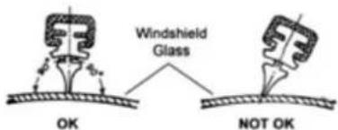
WARNING

Do not attempt to remove dirt from a dry windshield with the wipers or you can damage the windshield and the wiper blades. Always wet the windshield with washer fluid before operating the wipers.
EXTENDED WARRANTY
TATA MOTORS recommends the purchase of its extended warranty program.
Coverage - Mechanical + Electrical
Benefits
• Insures you against unforeseen break down repair bills.
- Documentation is simple and hassle free.
• Near cashless & speedy claim
Term
36 + 12 months or 150000 kms whichever occurs first
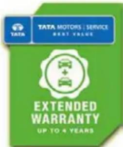
Extended Warranty is available in the dealership from where you have purchased your vehicle. We strongly recommend purchase of Extended Warranty at time of purchase of your vehicle. Extended Warranty can be availed till 421 days from date of purchase of vehicle. The Dealer Service Marketing Executive shall explain to you the Terms and conditions, Coverage and Owner's responsibility.
Extended Warranty Booklet & Cover Note
The Extended Warranty booklet and cover note is the basis of the contract between TATA MOTORS LIMITED and the Owner of the vehicle shown on the Extended Warranty booklet. The Customer is to retain this booklet and the same to be produced to the dealer while claiming benefit s under Extended Warranty.
Note
- The 12 months extended warranty does not follow the 36 months Manufacturer's warranty.
- The extended warranty comes into force once the manufacturer's warranty expires e.g. after 36 Months.
- It is more restrictive as by the time it comes into force the vehicle is already 36 months old.
VEHICLE CARE
What is covered?
- Mechanical / Electrical break down as defined in this warranty and confirmed by the dealer within the stipulated terms and conditions.
- TATA MOTORS dealer shall either repair or replace any part found to be defective with a new part or an equivalent at no cost to the owner for parts or labour.
• Such defective parts which have been replaced will become property of TATA MOTORS LIMITED. - Comprehensive list of parts covered is mentioned in the page 9-12 of the Extended Warranty Booklet.
What is not covered?
Please refer the Extended Warranty Booklet for details of the exclusion list.
Owner's Responsibility:
- Proper use, maintenance and care of the vehicle in accordance with the instructions contained in the Owner's Manual and
• Service Booklet. The records of the same to be ensured in Owner's Manual.
• Retention of maintenance service bills.
I / We have been explained the Terms and conditions, Coverage and Owner's responsibility by the Dealer Service Marketing Executive.
☐ I wish to avail / ☐ Do not wish to avail extended warrant policy.
Customer's Signature
Dealer's Signature
VALUE ADDED SEVICES
Why are Corrosion Protection Waxes necessary?
Corrosion is caused by:
Water / salt water acid rain & atmospheric fallouts.

WÜRTH

Auto krom™
Critical areas are:
• Cavities: joints, crevices, spot welds, underbody
• Corrosion is the most important factor when we talk about the vehicle life. If you treat your vehicle you can prolong the life.
- It is very dangerous to drive around in a corroded vehicle.
- The corrosion creeps onto the vehicle from the inside and from the outside. The most dangerous kind of corrosion is often not discovered until it is too late.
Benefits of Anti - Rust treatment:
• A professionally applied range of world class products offering real value to the new and used vehicle customer.
- The treatment has been developed to withstand the harshest environmental and climatic conditions (rust. Pollutants, stone and gravel impact, etc.)
• Insulate cabin space from external noises.
- Expensive tin work and Denting / Painting avoided.
• Higher resale value for the vehicle.
• Higher safety – uncorroded vehicle
• 10 free checkups available
VEHICLE CARE
Engine Wax Treatment
Engine Wax is a beige colored transparent lacquer coating on the engine compartment.
• Corrosion Prevention for the Engine compartment.
- Neat, clean and New Look to Engine compartment.
- No effect on MPFI vehicles.
- Engine wax can withstand upto 200 degrees temperature.
- No need of cleaning the engine compartment with diesel once engine wax is sprayed.
• Life of over a year.
Sound Deadening System
Door vibration deadeners - These pads when stuck on the insides of the sheet metal increase sheet metal rigidity, reduce vibrations and increase riding comfort.
• Used for reducing the sheet metal vibration in a vehicle.
• Product to be used once in the life of the vehicle - Life Time Warranty
- Effect is life long i.e. until & unless pads are physically removed.
- Negligible increase in Weight & hence no effect on fuel consumption.
- Areas covered - four doors, rear quarter panels & dickey. In case of diesel vehicles, can be used in the bonnet.
TATA MOTORS has tied up with M/s Wurth, M/s Autokrom, M/s 3M India Ltd & M/s Bardahl for these world class treatment at affordable prices. These treatments are available in all authorized workshops. The Dealer Service Marketing Executive will explain to you the benefits and terms and conditions of this treatment.
I / We have been explained the Benefit s, Terms and conditions and the prices of these treatment s by the Dealer Service Marketing Executive.
☐ I wish to avail / ☐ Do not wish to avail extended warrant policy.
Customer's Signature
Dealer's Signature
Vehicle Exterior Enrichment
Why vehicles are painted?
- For Corrosion protection of the metal surfaces.
- Ease of application from other corrosion protection treatments.
- Cheaper than other corrosion protection methods e.g. Galvanizing, anodizing.
- For decoration and identification.
Various Environmental Hazards affecting paints
Environmental hazards: destroy your vehicle's finish.
Even as your new vehicle rolls off the assembly line, the paint is not protected.
The enemy
Ultraviolet Rays, Pollution, Tree Sap, Bird Droppings, Car Wash Chemicals, Road Salt, Acid Rain.
Benefits: Vehicle Exterior Enrichment
- Removal of medium stains and dirt from all interior parts of the vehicle i.e. carpet, upholstery and roof lining.
• Cleaning of windshield and all windows (inside and outside) - Dressing of all internal plastics (e.g.: door pad trims) and rubber parts.
- The treatment involves cleaning and dressing of all parts of the exposed interiors.
- Specialized protection for seat fabric from liquid spills.
TATA MOTORS has tied up with M/s Wurth and M/s Autokrom for this world class treatment at affordable prices. This treatment is available in all authorized workshops. The Dealer Service Marketing Executive will explain to you the benefits and terms and conditions of this treatment
VEHICLE CARE
Engine Flush treatment helps in
- Safely and effectively cleaning and removing oxidized particles and fluid contamination left behind from previous oil changes
• Preventing further deposits
• Freeing sticky lifters and rings - Chemically "tuning" the engine during driving
• Restoring pep and power - Removing sludge from valve train
- Promoting fuel economy and improving overall engine operation
Special products used for improving compression
To fortify new oil and seal rings for optimum performance, special products from BG (RF7) and Bardhal (Special Duty) are added to new engine oil. This makes it suitable for petrol and diesel engine applications
Resulting in:
- Improved engine compression
- Increased power and increased fuel economy
- Reduced start-up wear
- Increased engine life, especially under severe service conditions
- Reduced emissions and oil consumption
- Improved power & performance of older engines
• Prevention of sludge, gum and varnish formation on engine parts both petrol & diesel engines
Please note: These are symptomatic treatments to be availed beyond 20000 kms and only when you have problems in your car as mentioned in first paragraph and are to be done only after you give your consent for carrying out these treatments.
TATA MOTORS has tied up with M/s HOEC Bardahl India Ltd and M/s BG for these world class treatment at affordable prices. These treatments are available in all authorized workshops. The Dealer Service Marketing Executive will explain to you the benefits and terms and conditions of this treatment.
I / We have been explained the Benefit s, Terms and conditions and the prices of these treatment s by the Dealer Service Marketing Executive.
I wish to avail / Do not wish to avail extended warrant policy.
Customer's Signature
Dealer's Signature
WARRANTY
14
WARRANTY
We WARRANT each TATA HEXA vehicle and parts thereof manufactured by us to be free from defect in material and workmanship subject to the following terms and conditions:
- This warranty for engine (Varicor) fitted in the vehicle shall be for a period of 36 months OR 1,50,000 kms, whichever is earlier from the date of sale of the vehicle.
The warranty for the rest of the vehicle shall be for a period of 36 months OR 1,00,000 kms, whichever is earlier from the date of sale of the vehicle.
-
Our obligation under this warranty shall be limited to repairing or replacing, free of charge, such parts of the car which, in our opinion, are defective, on the car being brought to us or to our dealers within the period. The parts so repaired or replaced shall also be warranted for quality and workmanship but such warranty shall be co-terminus with this original warranty.
-
Any part which is found to be defective and is replaced by us under the warranty shall be our property.
-
As for such parts as Tyres, Batteries, Audio and / or Video equipment (if any), etc. not manufactured by us but supplied by other parties, this warranty shall not apply, but buyers of the car shall be entitled to, so far as permissible by law, all such rights as we may have against such parties under their warranties in respect of such parts.
-
This warranty shall not apply if the car or any part thereof is repaired or altered otherwise than in accordance with our standard repair procedure or by any person other than from our sales or service establishments, our authorized dealers, service centres or service points in any way so as, in our judgment which shall be final and binding, to affect its reliability, nor shall it apply if, in our opinion which shall be final and binding, the car is subjected to misuse, negligence, improper or inadequate maintenance or
accident or loading in excess of such carrying capacity as certified by us, or such services as prescribed in our Owner's Manual are not carried out by the buyer through our sales or service establishments, our authorized dealers, service centres or service points.
-
This warranty shall not apply to the replacement of normal wear parts, including without limitation, spark plugs, drive belts, hoses, wiper blades, fuses, clutch disc, brake shoes, brake pads, cables and all rubber parts (except oil seal and glass run).
-
This warranty shall not cover any inherent normal deterioration of the car or any of its parts arising from the actual use of the car or any damage due to negligent or improper operation or storage of the car.
-
This warranty shall not apply to normal maintenance services like oils & fluid changes, head lamps focusing, fastener retightening, wheel balancing
WARRANTY
and alignment, tyre rotation, adjustment of valve clearance, fuel timing, ignition timing and consumables like bulbs, fuel, air & oil filters and gas leaks in case of air conditioned cars.
9. This warranty shall not apply to any damage or deterioration caused by environmental pollution or bird droppings. Slight irregularities not recognized as affecting the function or quality of the vehicle or parts, such as slight noise or vibration, defects appearing only under particular or irregular operations are items considered characteristics of the vehicle.
10. This warranty shall be null and void if the car is subjected to abnormal use such as rallying, racing or participation in any other competitive sport. This warranty shall not apply to any repair or replacements as a result of accident or collision.
11. This warranty is expressly in lieu of all warranties, whether by law or otherwise, expressed or implied, and all other obligations or liabilities on our
part and we neither assume, nor authorize any person to assume on our behalf, any other liability arising from the sale of the car or any agreement in relation thereto.
-
The buyer shall have no other rights except those set out above and have, in particular, no right to repudiate the sale, or any agreement or to claim any reduction in the purchase price of the car, or to demand any damages or compensation for losses, incidental or indirect, or inconvenience or consequential damages, loss of car, or loss of time, or otherwise, incurred or accrued.
-
Any claim arising from this warranty shall be recognized only if it is notified in writing to us or to our authorized dealer without any delay soon after such defects as covered & ascertained under this warranty.
-
This warranty is fully transferable to subsequent vehicle owner. Only unexpired remaining period of warranty applies.
-
We reserve our rights to make any change or modification in design of the car or its parts or to introduce any improvement therein or to incorporate in the car any additional part or accessory at any time without incurring any obligation to incorporate the same in the cars previously sold.
ENVIRONMENT SAFETY
15
ENVIRONMENT SAFETY
TATA MOTORS LTD. is committed to produce vehicles using environmentally sustainable technology. A number of features have been incorporated in TATA MOTORS passenger vehicles which have been designed to ensure environmental compatibility throughout the life cycle of the vehicle. We would like to inform you that your vehicle meets emission norms and this is being regularly validated at the manufacturing stages.
As a user you too can protect the environment by operating your vehicle in a proactive manner. A lot depends on your driving style and the way you maintain your vehicle. We have given a few tips for your guidance.
Driving
- Avoid frequent and violent acceleration.
- Do not carry any unnecessary weight in the vehicle as it overloads the engine. Avoid using devices requiring high power consumption during slow city traffic condition.
- Monitor the vehicle's fuel consumption regularly and if showing rising trend get the vehicle immediately attended at the Company's Authorised Service Outlets.
- Switch off the engine during long stops at traffic jams or signals. If you need to keep the engine running, avoid unnecessary revving it up or stopping and starting.
- It is not necessary to rev up the engine before turning it off as it unnecessarily burns the fuel.
- Shift to higher gears as soon as it is possible. Use each gear upto 2/3rd of its maximum engine speed.
Maintenance
- Ensure that recommended maintenance is carried out on the vehicle regularly at the Authorised Service Outlets.
- As soon as you see any leakages of oil or fuel in the vehicle we recommend to get it attended immediately.
- Use only recommended grades and specified quantity of lubricants.
- Get your vehicle checked for emission periodically by an authorised dealer.
- Ensure that fuel filter, oil filter and breather are checked periodically and replaced, if required, as recommended by TATA MOTORS.
- Do not pour used oils or coolants into the sewage drains, garden soil or open streams. Dispose the used filters and batteries in compliance with the current legislation.
- Do not allow unauthorized person to tamper with engine settings or to carry modifications on the vehicle.
- Never allow the vehicle to run out of fuel.
- Parts like brake liners, clutch discs should be vacuum cleaned. Do not use compressed air for cleaning these parts which may spread dust in the atmosphere.
While carrying out servicing or repairs of your vehicle, you should pay keen attention to some of the important engine aggregates and wiring harness which greatly affect emission. These components are:
- Fuel injection equipment's - pump, rail, injectors, nozzles and high pressure pipes.
• Air Intake & Exhaust system, especially for leakages. - Cylinder head for valve leakage.
• All filters such as air, oil and fuel filters (check periodically). - Turbocharger
• EGR system and components
• Electrical connections - If the 'Check Engine' and 'MIL' lamp continuously glows, please take the vehicle to a TATA MOTORS authorized service outlet.
- EMS wiring harness i.e. electrical connections to all sensors and actuators.
This Owner's manual contains further information on driving precautions and maintenance care leading to environment protection. Please familiarize yourself with these aspects before driving.
VEHICLE SERVICE & SERVICE COUPONS
16
VEHICLE SERVICE
Vehicle Record
| Km. reading | Fuel filled | Fuel consumption | Remarks / complaints |
Record of Warranty Repairs Carried Out
| Date | Odometer | Repair reading (km) | Particulars of Repair Order No. | Servicing Dealer's Signature & Stamp |
VEHICLE SERVICE
Record of Services Performed
| Recommended Service | Date | Odometer Reading | Repair Order No. | Servicing Dealer's Signature & Stamp |
| At km. | ||||
| PDI | ||||
| 5,000 | ||||
| 10,000 | ||||
| 20,000 | ||||
| 30,000 | ||||
| 40,000 | ||||
| 50,000 | ||||
| 60,000 | ||||
| 70,000 | ||||
| 80,000 | ||||
| 90,000 | ||||
| 1,00,000 |
Chassis No. ....
Engine No. ....
Gear Box No. ....
At 10,000-10500 km OR 6 months whichever is earlier
Please bring your vehicle for this service
As per details given in the SERVICE SCHEDULE
WORK DONE TO MY SATISFACTION
Sign. Of customer......
Speedo Reading ....Km. seal O.K./ Broken
R.O. No. Date
Dealer's / Authorised Service Centre's
Stamp & Signature....
Chassis No. ....
Engine No. ....
At 20,000-20500 km OR 12 months whichever is earlier
Please bring your vehicle for this service
As per details given in the SERVICE SCHEDULE
WORK DONE TO MY SATISFACTION
Sign. Of customer....
Speedo Reading ....Km. seal O.K./ Broken
R.O. No. Date
Dealer's / Authorised Service Centre's
Stamp & Signature....
2
FREE
LABOUR
3
FREE
LABOUR
At the time of delivery of vehicle, please ensure that pre-delivery inspection has been carried out as per details given in the SERVICE SCHEDULE.
Chassis No. ....
Engine No. ....
Gear Box No. ....
PDI
FREE
LABOUR
WORK DONE TO MY SATISFACTION
Speedo Reading ....Km. seal O.K./ Broken
R.O. No. Date
Dealer's / Authorised Service Centre's
Stamp & Signature....
Chassis No. ....
Engine No. ....
At 5,000-5,500 km OR 3 months whichever is earlier
Please bring your vehicle for this service
As per details given in the SERVICE SCHEDULE
1
FREE
LABOUR
WORK DONE TO MY SATISFACTION
Sign. Of customer......
Speedo Reading ....Km. seal O.K./ Broken
R.O. No. Date
Dealer's / Authorised Service Centre's
Stamp & Signature....


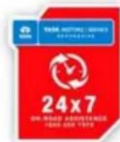


HORIZONEXT
HEXA
FROM TATA MOTORS

TATA MOTORS | SERVICE
RESPONSIVE·RELIABLE·BEST VALUE
Call us: 1-800-209-7979
Mail us: customercare@tatamotors.com
Visit us: service.tatamotors.com
5424 5840 9901
Developed by: Technical Literature Cell, ERC.

- CUSTOMER ASSISTANCE
- Dear Customer,
- TATA MOTORS
- IMPORTANT INFORMATION
- WARNING
- NOTE
- CONTENTS
- Safety
- Opening & Closing
- Dashboard & Features
- Stowage Areas
- Climate Control
- Starting & Driving
- Driver Assist
- Drive Modes
- Maintenance
- Technical Information
- Vehicle Care and Value Added Services
- SAFETY
- 01
- Safe Driving
- Safe driving depends on:
- Safety tips
- Driving through water
- Driving on a rainy day
- Driving through wet roads
- Night driving
- Driving on gradients
- Driving on highway
- Occupant Safety
- Seat Belts
- Proper use of the seat belts
- Lap belt
- Pregnant woman
- Child Safety
- Important safety notes
- Child Restraint System (CRS)
- Selection and installation of CRS
- Recommended CRS position
- Storage for CRS
- Check list
- Child Lock
- Window Inhibit Switch
- Pets in the vehicle
- Air Bags - Supplemental Restraint System
- Side Air bags
- Curtain air bags
- Airbag warning label
- When Braking:
- EBD (Electronic Brake-force Distribution)
- E-Key
- Unlocking principle
- Engine starting
- Loss of keys
- Immobilizer - Anti-Theft Device
- OPENING AND CLOSING
- 02
- Key
- Unlocking
- Approach light
- Locking all doors
- Folding key blade in / out
- Remote key features
- Vehicle search
- Automatic activation of immobilizer
- Theft detection
- Auto locking / unlocking of doors / auto relock
- Anti-grab / anti-scan coding
- Force panic alarm
- Sleep Mode
- Important
- Refer 'Maintenance' section for battery replacement.
- Doors
- Door locking / unlocking with mechanical key
- Opening the doors from inside
- Windows
- Express down (if equipped)
- Individual switches
- Inhibit OFF (Released position)
- Inhibit ON (pressed position)
- Bonnet
- Opening
- Closing
- Fuel Lid
- Manual Fuel flap opening
- DASHBOARD & FEATURES
- 03
- DASHBOARD AND FEATURES
- Cockpit
- Welcome Strategy
- Fuel Gauge
- Instrument Cluster
- Audio Reminders
- 1) Key In reminder
- 2) Parking Lamp ON reminder
- 3) Parking Brake ON reminder
- 4) Reverse Gear reminder
- Auto Light (if equipped)
- OFF
- Parking Lamp
- Headlamp
- Fog Lamp (if equipped)
- 1) Illumination control switch
- 2) Headlamp levelling switch
- Automatic DRL Deactivation and Activation
- To Deactivate -
- To Activate -
- 0) OFF position
- 1) Intermittent wipe
- 2) Slow Wipe
- 3) Fast Wipe
- 4) Flick Wipe (spring return)
- 5) Front windshield wash and wipe
- 6) Rear windshield wash and wipe
- Rear intermittent wipe
- Rear wiper continuous 'ON'
- Auto front wipe (if equipped)
- Combi-Switch (RH Stalk)
- Left Turn signal
- Right Turn signal
- Lane Change Signal
- Hi-Beam
- High beam Flash (spring return)
- TRIP, FUEL, SET functions
- Fascia Switches
- Rear Park Assist Switch
- Hill Descent Control (HDC) Switch
- 4 x 2 Switch (if equipped)
- Door Lock / Unlock Switch
- Mic
- Steering Wheel Switches (LHS)
- Volume
- Mute / phone reject
- Seek forward / backward
- Steering Wheel Switches (RHS)
- Phone receive / PTT (if equipped)
- Cruise control switches
- Infotainment System
- Speakers
- Audio Amplifier
- Roof Lamps
- Sun Blinds - Rear Windows
- STOWAGE AREAS
- 04
- Top Stowage Compartment
- Chiller Glove Box
- Lower Glove Box
- Below The Arm Rest
- Cup Holders
- On Central Console
- Middle Row (Central Console)
- Third Row Seat
- Foldable Arm Rest (if equipped)
- Utility Pockets (front & rear doors)
- Tailgate (Trunk) Compartment
- Third row seat folding
- Second row seat folding
- To Access Third Row Seats
- Coat Hook
- Goggle Case
- CLIMATE CONTROL
- 05
- Air Vents
- Front air vents
- Front side air vents
- Second row center console air vents
- Rear side air vents
- Heating, Ventilation and Air Conditioning (HVAC)
- Automatic Operation
- Semi-automatic Operation
- A.C. ON/OFF Button
- Temperature Control Knob
- Air intake selector
- Recirculation mode: (Indicator light ON)
- Fresh Air mode: (Indicator light OFF)
- Windscreen Defroster Button
- (Front)
- Demister / Defogger Button
- ECON A.C.
- Sensors
- Solar Sensor
- In-Vehicle Sensor
- Outside ambient temperature sensor
- Manual Heating, Ventilation and Air conditioning (HVAC)
- Recirculation Button
- Blower Speed Control Knob
- A.C. mode ON-OFF Button
- Rear A.C. Operating instruction
- STARTING AND DRIVING
- 06
- Pre Driving Checks
- Make sure that:
- Daily check:
- Adjust:
- Weekly check:
- Driving Tips
- Operating conditions:
- Personal driving style
- Good driving practices
- Tips for obtaining better fuel efficiency
- Running-in period
- Seat Adjustments
- Front seat adjustments
- Seat backrest angle adjustment
- Seat height adjustment
- Seat forward / rearward adjustment
- Rear seats adjustment
- Motorized outer rear view mirrors (ORVM) and power fold (if applicable)
- To adjust the ORVM:
- Demister (if applicable)
- To block glare from side windows
- Vanity mirror lights (if equipped)
- Steering Wheel Adjustment
- To adjust the steering wheel
- Steering lock cum ignition switch
- Illuminated Key Ring
- Starting the Engine
- Starter Protection System
- Starting off
- Manual Transmission
- Automatic Transmission
- Gear Shifting and Driving Manual Transmission
- Gear indication
- Reverse (R)
- Neutral (N)
- Drive Mode (D)
- Sport / Manual (S/M)
- ‘+’ For Upshifting in Manual mode
- ‘-’ For Downshifting in Manual mode
- Automatic transmission- manual mode
- Drive mode indicator
- Auto Mode
- Sport Mode
- Manual Mode
- Transmission Overheating
- Transmission Fault
- Braking
- Braking on downhill gradients
- Switching OFF the engine
- For Automatic Transmission,
- Vehicle parking
- DRIVER ASSIST
- 07
- Electronic Stability Program (ESP) (if equipped)
- ESP Operation
- ESP and tyre sizes
- Traction Control System (TCS)
- Vehicle Dynamic Control (VDC)
- Roll over Mitigation (ROM)
- Cornering Stability Control (CSC)
- Electronic Brake Pre-fill (EBP)
- Engine Drag Torque Control (EDTC)
- Hill Descent Control (HDC)
- Torque - On - Demand (TOD) Transfer case (if equipped)
- Using TOD system (if equipped)
- Cruise Control (if equipped)
- Cruise Control Switch on Steering Wheel
- Setting cruise speed
- Changing the set cruise speed
- Deactivating cruise control
- Resuming the set cruise speed
- Reverse Park Assist with Camera (if equipped)
- Activation
- Reverse gear
- > Infotainment system touch screen
- Deactivation
- Color Guidelines
- Understanding Guidelines Indication
- Cyan line
- Green Line
- Yellow Line
- Red Line
- Using camera
- Cleaning camera
- Ultrasonic Reverse Park Assist (if equipped)
- Operation:
- Reverse gear
- Reverse Park Assist Switch
- LED Indications
- Infotainment music system touch display
- Deactivation:
- Limitations
- Preventive maintenance
- Audio Settings
- Volume Setting
- Mix With Audio
- Park Assist Tone
- Park Assist Delay Timer
- Fault Indications
- Critical Fault
- Warnings
- DRIVE MODES
- 08
- Drive Modes (if equipped)
- Drive Mode Selection Switch
- Auto -
- Comfort -
- Drive Mode Functionality
- Drive Mode Selection
- 1) AUTO to COMFORT mode
- 2) AUTO to ROUGH ROAD mode
- 3) COMFORT to DYNAMIC mode
- Vehicle applicability: XT (without TOD)
- Drive Control Shift Denied
- Drive Control System Fault
- Drive Control System Display
- Mood Lighting Display
- AMBIENT MOOD LIGHTS
- 09
- Intensity selection bar
- All
- Modes
- Area Selection
- Color selection
- Activation of Mood Lighting
- Option:1
- Option:2
- Selecting Color
- Selecting Area
- Switching Off Mood Lighting
- Ambient Mood Lights (Entry/Exit)
- EMERGENCY AND BREAKDOWN ASSISTANCE
- 10
- Emergency Equipments
- First aid kit
- Tool kit
- Inertia switch
- In Case of Flat Tyre
- Changing flat tyre
- Jump Lead Starting
- Towing
- Installing the Tow hook
- Recommended towing
- Fuses
- Checking and replacing fuses
- Bulbs
- X 7 Road Assistance
- Standard procedure when calling for On Road Assistance in case of a breakdown:
- Coverage under 24 X 7 On Road Assistance program
- Exclusions
- X 7 On Road Assistance Program does not apply to
- Disclaimer
- Exclusion of Liabilities
- MAINTENANCE
- 11
- Maintenance and Service
- Engine Oil Level
- Brake Fluid Level
- Engine Coolant Level
- Power Steering Fluid Level
- Windshield Washer Fluid Level
- Battery
- For location of battery, please refer Engine Compartment section.
- Turbocharger
- Lubrication of Turbocharger
- Intercooler
- Transmission Air Oil Cooler
- Maintenance recommendations:
- Catalytic Converter
- Tyres
- Inflation
- Tyre pressure sticker location
- Regular checking of wheels & tyres
- Special care for tubeless tyres:
- Tyre rotation
- Wheel Balancing
- Wheel Alignment
- Remote Key Battery Replacement
- On Board Diagnostic (OBD II) System
- SERVICE INSTRUCTIONS
- Vehicle Parking at One Place for Long Duration (Non - Use Maintenance)
- TECHNICAL INFORMATION
- 12
- Fuel Specification
- Fuel
- Lubricants
- VEHICLE CARE
- 13
- Washing
- Cleaning of Carpets
- Cleaning of Windows, Front and Rear Glasses
- Waxing
- Polishing
- Interior fabric cleaning tips
- Paint Care
- Proper cleaning
- Periodic Inspection
- Proper Parking
- Wiper care
- EXTENDED WARRANTY
- Benefits
- Term
- Extended Warranty Booklet & Cover Note
- What is covered?
- What is not covered?
- Owner's Responsibility:
- VALUE ADDED SEVICES
- Critical areas are:
- Benefits of Anti - Rust treatment:
- Engine Wax Treatment
- Sound Deadening System
- Vehicle Exterior Enrichment
- Why vehicles are painted?
- Various Environmental Hazards affecting paints
- The enemy
- Benefits: Vehicle Exterior Enrichment
- Engine Flush treatment helps in
- Special products used for improving compression
- Resulting in:
- WARRANTY
- 14
- ENVIRONMENT SAFETY
- 15
- Driving
- VEHICLE SERVICE & SERVICE COUPONS
- 16
- VEHICLE SERVICE
- WORK DONE TO MY SATISFACTION
- 2
- FREE
- LABOUR
- 3
- PDI
- 1
- HEXA
Brand : Tata
Model : Hexa (2017)
Category : Car