
RGB 109xi - Audio/video converter Extron - Free user manual and instructions
Find the device manual for free RGB 109xi Extron in PDF.


| Product Type | Audio/Video Converter |
| Brand | Extron |
| Model | RGB 109xi |
| Dimensions (H x W x D) | 1.7 in x 17.4 in x 9.5 in (43 mm x 442 mm x 241 mm) |
| Weight | 5.5 lbs (2.5 kg) |
| Power Consumption | 30 watts, 100-240 VAC, 50/60 Hz |
| Video Inputs | 1x RGBHV on 15-pin HD, 1x Composite Video on BNC |
| Video Outputs | 1x RGBHV on 15-pin HD |
| Supported Video Formats | RGBHV, RGBS, RGsB, Composite Video |
| Max Resolution | 1600x1200 @ 60 Hz |
| Audio Input | 1x Stereo mini jack (unbalanced) |
| Audio Output | 1x Stereo mini jack (unbalanced) |
| Rack Mountable | Yes, 1U height |
| Front Panel Controls | Input select, Audio level, Sync polarity |
| Cooling | Fan cooled, variable speed |
| Operating Temperature | 32°F to 122°F (0°C to 50°C) |
| Storage Temperature | -4°F to 158°F (-20°C to 70°C) |
| Humidity | 10% to 90% noncondensing |
| Certifications | CE, FCC Class A, UL, CUL |
| Included Accessories | Power cord, 15-pin HD cable, rack ears, manual |
| Maintenance | Keep vents clean, use dry cloth; no user-serviceable parts |
Frequently Asked Questions - RGB 109xi Extron
User questions about RGB 109xi Extron
0 question about this device. Answer the ones you know or ask your own.
Ask a new question about this device
Download the instructions for your Audio/video converter in PDF format for free! Find your manual RGB 109xi - Extron and take your electronic device back in hand. On this page are published all the documents necessary for the use of your device. RGB 109xi by Extron.
USER MANUAL RGB 109xi Extron
natural_image
Two black electronic devices with connected cables and ports, one showing a display and cable (no visible text or symbols)RGB 109xi and RGB 112xi
Dedicated Computer-Video
Interfaces with Audio and ADSP™
68-410-01
Rev. D 10 07
Precautions
Safety Instructions • English

This symbol is intended to alert the user of important operating and maintenance (servicing) instructions in the literature provided with the equipment.

This symbol is intended to alert the user of the presence of uninsulated dangerous voltage within the product's enclosure that may present a risk of electric shock.
Caution
Read instructions • Read and understand all safety and operating
The following table is provided in the image.
Rebin instructions • The safety instructions should be copy for future
Hollman's
www.163.com.cn (http://www.163.com.cn) www.163.com.cn
Arid Allachamants * Do not use both or allachamants that are re-
recommended by the equipment manufacturer because this may be
lacanlou
to consider a revenue
The following table is provided in the image.
at Kachman, coles de pse
segmented, also as a card of paper.
Power source • The equipment should be assumed only from the power source indicated on the product. This equipment is intended to be used with a rail power system with a grounded (neutral) conductor. For third groundings pin is a safety fixture, it does not attempt to space or disable it.
Power disconNECTION • To remove power from the equipment, addly, remove all power cards from the roof of the equipment, or for disassembly power reader and deacoustic, or from the power source exceptally pool plug.
Power-cured protection. * Power cards should be noted so that they are no, likely to be imposed on or probably have placed room or age net them
Servicing • Rate: all servicing to qualified service personnel. Items are no user-
servikable parts inside. To prevent the rise of shock, do not attempt to serve
This summarized yourself becomes opening or removing acres may expose you to dangerous values or other benefits.
Kats and surprises: Like arguments you can help in the purpose, then we
Share and openings - In the capital, the CDS of 1.50 in the company, there are provided to prevent exposure of or specifying company-wide. These projects
rinal naverite blocked by other aspects.
Lithium battery * There is a danger of exposure that battery is increasingly
replicate. Replace it only will. In sense of significant type recommendations by the pastellectomy. Disperse with a double arrow indicating to the microscopy
2014年
2、本次股东大会决议的有效期
Avertissement
the past the fact. And a visit the airport, which is said to be present in the next week.
- Diven, makes the classes part of a class.
Lithium latitata • It is large, d'exploitation city, a complex best incolective 2019.
Измероза архоза архоза архоза
aux interactions du tarristant.
Vorsicht
[1] αi (mainly the main part of the main part of the main part of the main part of the main part of the main part of the main part of the main part of the main part of the main part of the main part of the main part of the main part of the main part of the main part of the main part of the main part of the main part of the main part of the main part of the main part of the main part of the main part of the main part of the main part of the main part.
The following table is provided in the image.
The following table is provided in the image.
This equipment has been tested and found to comply with the limits for a Class A digital device, pursuant to part 15 of the FCC Rules. Operation is subject to the following two conditions: (1) this device may not cause harmful interference, and (2) this device must accept any interference received, including interference that may cause undesired operation. The Class A limits are designed to provide reasonable protection against harmful interference when the equipment is operated in a commercial environment. This equipment generates, uses, and can radiate radio frequency energy and, if not installed and used in accordance with the instruction manual, may cause harmful interference to radio communications. Operation of this equipment in a residential area is likely to cause harmful interference, in which case the user will be required to correct the interference at his own expense.

This unit was tested with shielded cables on the peripheral devices. Shielded cables must be used with the unit to ensure compliance with FCC emissions limits.
Table of Contents
Chapter 1 • Introduction ...... 1-1
About this Manual 1-2
About the Interfaces 1-2
Features 1-3
Chapter 2 • Controls and Installation ..... 2-1
Front and Rear Panels 2-2
Front panel features 2-2
Rear panel features 2-3
Installation 2-5
Overview 2-5
Setting internal jumpers 2-6
Mounting the interface 2-9
Cabling 2-11
Connecting audio 2-12
Unbalanced audio 2-12
Balanced audio 2-13
Appendix A • Reference Information ......A-1
Specifications....A-2
Part Numbers ......A-4
Included parts ......A-4
Optional accessories ......A-4
BNC cables ......A-5
Mounting Templates ......A-6
All trademarks mentioned in this manual are the properties of their respective owners.
68-410-01
Rev D
10 07
Table of Contents, cont'd

RGB 109xi and RGB 112xi
1 Chapter One
Introduction
About this Manual
About the Interfaces
Features
Introduction
About this Manual
This manual documents two dedicated RGB interface units: the RGB 109xi, and the RGB 112xi. Unless otherwise specified, references to "the interface" in this manual pertain to the features or operation of both interfaces.
About the Interfaces
Both dedicated interfaces have the same features, but each works with a specific type of computer.
The RGB 109xi is a high-resolution, dedicated VGA/XGA/SVGA/SXGA computer-video interface. It uses a 15-pin HD connector.

Figure 1-1 — RGB 109xi interface
The RGB 112xi is a high-resolution, universal workstation interface that is compatible with all workstations that use a 13W3 video connector, such as Sun, IBM PowerPC, SGI, and NeXT workstations.

Figure 1-2 — RGB 112xi interface
NOTE For each RGB 112xi, Extron provides a multi-frequency termination adapter (MFTA) to be used if there is no local monitor. The adapter is attached by a chain to the interface, and an instruction card is attached to the adapter.
Features
Each interface includes the features listed below. See "Front and Rear Panels" on page 2-2 for information about the controls.
ADSP ™ (Advanced Digital Sync Processing ™ ) — Allows sync processing operations, such as horizontal centering, to occur without affecting the signal's sync timing. This allows horizontal centering to be applied to signals that are output to digital display devices, such as LCD (liquid crystal display) projectors, DLP (digital light processing) projectors, and plasma displays.
Auto power — Turns on power to the interface automatically when a video signal is received from the computer. You can determine that the interface is on if the scan rate indicator LCD displays a scan rate.
Buffered local monitor output — Allows you to view the displayed image on a local monitor located up to 150 feet from the interface without signal reflections or crosstalk.
Horizontal shift — Allows you to adjust the horizontal placement of the image on the screen. Also called "horizontal centering".
Gain/Peak control — Increases video signal voltages to compensate for signal degradation caused by long cable lengths.
Scan rate indicator LCD — Displays the horizontal and vertical sync frequencies of the computer, and the minimum and maximum points of adjustments to horizontal shift.
Introduction, cont'd

RGB 109xi and RGB 112xi
2 Chapter Two
Controls and Installation
Front and Rear Panels
Installation
Controls and Installation, cont'd
Front and Rear Panels
Front panel features

Figure 2-1 — Front panel features
① Video Input cable — Attaches the interface to the computer or workstation. The type of connector depends on the interface model:
RGB 109xi: 15-pin HD male RGB 112xi: 13W3 male
② Buffered Local Monitor Output Connector — Attaches to the local monitor's video signal cable. The type of connector depends on the interface model:
RGB 109xi: 15-pin HD female RGB 112xi: 13W3 female
NOTE If you are not using a local monitor with the RGB 112xi, you must attach an MFTA (multi-frequency termination adapter) to simulate a monitor.
③ ID Pin switches (RGB 109xi only) — Allows the user to set the correct ID bit termination:
ID PIN 4 & ID PIN 11

On — Set both pins to On (up) if you are using the RGB 109xi interface with a laptop computer that is not attached to a local monitor.
Off — Set both pins to Off (down) if you are attaching a local monitor to the interface.
④ Horizontal Shift control — Controls the screen image horizontal centering. To adjust the horizontal shift, turn the knob in either direction and observe the left/right movement of the image on the screen. Stop when the image is centered.
NOTE If the DDSP ™ DIP switch on the rear panel (3) is set to On, the horizontal shift control is disabled.
While the horizontal shift control is active, "H-SHIFT" appears in the scan rate indicator LCD (5) and for a further three seconds after the control is no longer active. When the control reaches its maximum or minimum point, "MAX" or "MIN" appears in the scan rate indicator LCD.
⑤ Scan rate indicator LCD — Shows the scan rate for the selected input, in kilohertz (kHz), on the top line. The vertical scan frequency, in Hz, appears on the bottom line. In addition, if the horizontal shift control is activated, or the minimum or maximum limits are reached, the LCD displays the status.
Rear panel features

Figure 2-2 — Rear panel features (RGB 112xi shown)
① IEC AC power connector — Use this standard AC power connector with the supplied IEC power cable.
② Gain/peak switch — Compensates for cable capacitance if the signal cable between the interface and the display device is longer than approximately 125 feet (38m). Turn the switch to the position that provides the best image on the output display device.
100% — Increases the output signal level and adds 100% of the maximum peaking to the signal.
Unity — The output level is the same as that of the input, with no added peaking.
50% — Increases the output signal level and adds 50% of the maximum peaking to the signal.
NOTE If the signal cable between the interface and the display device is shorter than approximately 125 feet (38m), and the Gain/Peak switch is set to a setting other than Unity, the image may be overcompensated. If the edges of the image seem to exceed their boundaries, or if thin lines and sharp edges look thick and fuzzy, try changing the Gain/Peak settings.
Controls and Installation, cont'd
③ DIP Switch — Controls sync on green output, Digital Display Sync Processing, and serration pulse removal.
1 — SOG (sync on green output)

On — If this switch is set to On (up), the interface outputs sync on green.
Off — If this switch is set to Off (down), output is RGBS or RGBHIV, depending on how the interface and projector are cabled.
2 — DDSP (Digital Display Sync Processing)
On — If this switch is set to On (up), the interface does not perform sync processing. This may be necessary for digital display devices, such as LCD, DLP, and plasma displays.
Off — If this switch is set to Off (down), the interface performs sync processing operations, such as horizontal shift, using Extron's ADSP.
NOTE Turning on the DDSP feature disables the horizontal shift control.
3 — SERR (serration pulses)
Many display devices, such as LCD and DLP projectors and plasma displays, must have serration pulses removed from the sync signal in order to display images properly. Flagging or bending at the top of the video image is a sign that the serration pulses should be removed.
On — If this switch is set to On, serration pulses are present on the output signal.
Off — If this switch is set to Off, serration pulses are not present on the output signal.
4 — SPARE — No function is assigned.
④ CPU dial switch (RGB 112xi only) — Use a Tweeker or a small screwdriver to set this switch to the type of computer attached to the RGB 112xi interface (IBM, Sun, or SGI), or if the computer produces sync on green only, set the switch to SOG.
⑤ RGB output —Connect coaxial cables to these female BNC connectors to an RGB output device. Connect cables for the appropriate signal type, as shown below.


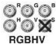
⑥ Audio output connector — One 5-conductor, 3.5-mm captive screw terminal for audio output. See page 2-13 for audio connection details.
Installation
Overview
The installation procedure is the same for the RGB 109xi and the RGB 112xi, except that each interface attaches to a different type of computer. See "Cabling" on page 2-11 for more information.
To install and set up the RGB 109xi or the RGB 112xi for operation, perform the following basic steps (the remainder of this chapter provides detailed steps):
1 Turn off power to the computer or workstation and its monitor, and unplug the power cable from each of these devices. Turn off power to the projector, and unplug its power cord.
2 Disconnect the monitor signal cable from the computer. If speakers are attached to the computer's sound card, disconnect them as well.
3 If desired, change the configuration of jumper J20 (sync polarity) or J40 (vertical sync width). See "Setting internal jumpers" on page 2-6.
4 Set the DIP switches ID bit configuration (SOG, DDSP, SERR). See "Rear panel features" on page 2-3.
5 If desired, attach the interface to a table or under a podium using an optional Extron mounting kit. See "Mounting the interface" on page 2-9.
6 Attach the interface to the computer, attach the local monitor, if used, to the interface, and attach the projector to the interface. See "Cabling" on page 2-11.
NOTE If you are not using a local monitor with the RGB 112xi, you must attach an MFTA (multi-frequency termination adapter) to simulate a monitor.
Controls and Installation, cont'd
7 Attach the interface to an audio system. See "Connecting audio" on page 2-12.
8 Plug the interface into a grounded AC power source.
9 Turn on the computer, monitor, and projector (or other display device).
10 The image from the computer should appear on the projector and monitor. If it does not, double check steps 3 through 6 and make adjustments as needed.
Setting internal jumpers
The jumpers inside the interface are set at the factory for optimal use by most systems. However, you can change a jumper setting to meet the needs of a particular system.
WARNING Changes to internal jumper settings must be performed by authorized service personnel only.
The user-configurable, internal jumpers control the following functions:
J20: Sync polarity jumper — This jumper adjusts the output sync polarity. Horizontal (H) and vertical (V) sync output can either follow input sync polarity, or be forced to negative.
- If the jumper is on pins 1 and 2, output H and V sync polarities are forced to negative.
- If the jumper is on pins 2 and 3, output sync polarities follow input sync polarity: The output sync signals' polarity is the same as the input polarity. This is the default setting.
J40: Vertical sync width jumper — This jumper adjusts the vertical sync pulse width. Some digital display devices have very specific requirements for incoming sync pulse width. If no picture appears, the picture cuts in and out, or the picture is scrambled, try adjusting the vertical sync pulse width or switching from ADSP to DDSP.
- If the jumper is on pins 1 and 2, the output vertical sync pulse will be short (narrow).
- If the jumper is on pins 2 and 3, the output vertical sync pulse will be wide. This is the default setting.
To change the jumper settings, do the following:
- If the power cord is attached, remove power from the interface by disconnecting the AC power cord from the unit.
- Remove the interface cover (the top half of the enclosure), as shown in figure 2-3. Remove the screws from the enclosure, slide the cover slightly towards the back of the enclosure, enough to clear the gain/peak switch, lift the cover, and place the cover upside down next to the base of the enclosure.
CAUTION Do not pull on the cable that attaches the cover to the base. Doing so could disconnect the cable from its connectors.
CAUTION Do not touch any switches or electronic components inside the interface. Doing so could damage the interface.

Figure 2-3 — Opening the interface cover
Controls and Installation, cont'd
- Note the positions of jumpers J20 and J40 before changing jumper settings (figure 2-4). There are two possible setting combinations for 3-pin jumpers:

pins 1 and 2 connected

pins 2 and 3 connected
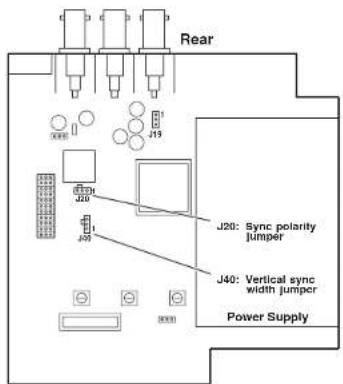
Figure 2-4 — Circuit board jumper locations
- To change the jumper configuration, use pliers to pull the jumper shunt off the pins, then place the jumper on the appropriate pins (figure 2-5).
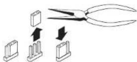
Figure 2-5 — Changing jumper settings
- Replace and fasten the enclosure cover, reversing step 2.
Mounting the interface
Under-desk Mounting
To mount the interface under a desk or in a podium using the under-desk mounting kit (Extron part number 70-077-01), do the following:
- Attach the mounting brackets to the interface using four machine screws supplied with the mounting kit (see figure 2-6).

natural_image
Technical line drawing of a rectangular electronic component with mounting holes and a side bracket (no text or symbols)Figure 2-6 — Attaching the under desk brackets
- Using the template on page A-6 to guide you, mark the four screw holes on the underside of the surface to which you are mounting the interface.
- Drill four pilot holes, each 3/32" (2.4 mm) in diameter by 1/4" (6.4 mm) deep, where marked on the template.
- Using the four wood screws provided, attach the brackets under the mounting surface (see figure 2-7).

natural_image
Isometric line drawing of a mechanical assembly with a flat plate and a rectangular base, showing internal components and arrows indicating motion (no text or symbols)Figure 2-7 — Under-desk mounting
Controls and Installation, cont'd
Through-desk mounting
To mount the interface through a desk or table using the through-desk mounting kit (Extron part number 70-077-02), do the following:
- Attach the mounting brackets to the interface using four machine screws and washers (supplied with the mounting kit), as indicated in figure 2-8.

Figure 2-8 — Attaching the through desk brackets
- Using the through-desk template on page A-6 to guide you, mark the four screw holes on the underside of the surface to which you are mounting the interface.
- Drill four pilot holes, each 3/32" (2.4 mm) in diameter by 1/4" (6.4 mm) deep, where marked on the template.
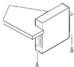
- Using the four wood screws provided, attach the brackets to the mounting surface, as shown in figure 2-9.
natural_image
Technical line drawing of a mechanical bracket or mounting component with mounting holes (no text or symbols)Figure 2-9 — Through-desk mounting
Cabling
Each interface can connect to the computer or workstation's local monitor and to a projector or other display device. Figures 2-10 and 2-11 show how to connect each of the interfaces.
1. Connect the local monitor's video signal cable to the interface connector labeled "Buffered Local Monitor Output".

flowchart
graph TD
    A["Extron RGB 109xi Interface"] -->|Front| B["Computer PC"]
    B --> C["Local Monitor"]
    C --> D["Power"]
    D --> E["Monitor Projector"]
    E --> F["Sound System"]
    F --> G["Rear"]
    G --> H["Computer"]
Figure 2-10 — RGB 109xi installation

flowchart
graph TD
    A["SUN or SGI Computer"] -->|Front| B["Extron RGB 112xi Interface"]
    B --> C["Sound System"]
    B --> D["Rear"]
    D --> E["Power Monitor"]
    D --> F["or Projector"]
    B --> G["or MFTA"]
Figure 2-11 — RGB 112xi installation
Controls and Installation, cont'd
- Connect the interface cable marked "Video input" to the computer's video output (where the monitor was originally connected).
- Connect the audio cable connector on the interface cable to the computer's audio line output (where the powered speakers were originally connected).
- Use BNC cables to attach the interface to a projector or other display device.
RGsB – If coax cables are connected and terminated (75 ohms) to the red, green, and blue channels only, and the SOG switch is set to On (see page 2-4), the output is sync on green.
RGsB
RGBS - If the S (composite sync) cable is connected, the output is composite sync.

RGBHV - If both the H & V cables are connected, the sync output is separate horizontal and vertical.

Connecting audio
Before connecting audio, determine whether your audio system is unbalanced or balanced. Then, follow the instructions on page 2-12 or 2-13, to connect unbalanced or balanced audio.
CAUTION Wiring the audio incorrectly may damage the audio output circuits.
Unbalanced audio
To attach the interface to an unbalanced audio system, do the following:
- Attach the audio cable to an unbalanced speaker input connector (tip and sleeve).

2-12 RGB 109xi and RGB 112xi • Installation
- Attach the audio cable to the captive screw connector (Extron part number 10-319-10) as shown below. Fasten down the captive screws inside the audio cable connector.

CAUTION Connect the sleeve(s) to ground (GND). Connecting the sleeve(s) to a negative (-) terminal will damage audio output circuits.
- Slide the audio cable connector into the audio output connector on the interface.
Balanced audio
To attach the interface to a balanced audio system, do the following:
- Attach the audio cable to a balanced speaker input connector (tip, ring, and sleeve).

- Attach the audio cable to the captive screw connector (Extron part number 10-319-10) as shown below. Fasten the captive screws inside the audio cable connector.

- Slide the audio cable connector into the audio output connector on the interface.
Controls and Installation, cont'd

RGB 109xi and RGB 112xi
Appendix A
Reference Information
Specifications
Part Numbers
Mounting Templates
Reference Information
Specifications
Specifications apply equally to both units, except where noted.
Video input
Number/type 1 analog RGBIV, RGBS, RGsB, RsGsBs
Connectors ...... RGB 109xi: 1 15-pin HD male, 48" (122 cm) long cable RGB 112xi: 1 13W3 male, 48" (122 cm) long cable
Nominal level(s) Analog — 0.3 V to 1.5 Vp-p
Maximum level(s) ...... Analog — 1.5 Vp-p
Impedance 75 ohms
Horizontal frequency ...... Autoscan 15 kHz to 130 kHz
Vertical frequency.... Autoscan 30 Hz to 120 Hz
Return loss ...... -30 dB @ 5 MHz
Maximum DC offset 4.0 V
Video throughput
Gain .... Unity, 0.725 Vp-p with 50% peaking, 0.750 Vp-p with 100% peaking
Bandwidth 300 MHz (-3 dB)
Video output
Number/type/format 1 analog RGBHV, RGBS, RGsB
Connectors ...... 6 BNC female RGB 109xi: 1 15-pin HD female local monitor output (buffered) RGB 112xi: 1 13W3 female local monitor output (buffered)
Nominal level ...... Analog 0.70 Vp-p, 0.725 Vp-p, or 0.750 Vp-p
Impedance 75 ohms
Return loss ...... -30 dB @ 5 MHz
Sync
Input type ...... RGBHV TTL (±), RGBS TTL (±), RGsB 0.3V (-), RsGsBs 1.3V (-)
Output type ...... RGBHV (±), RGBS(±), RGsB (-)
Input level 2.0 V to 5.5 Vp-p with ±0.2 VDC offset (max.)
Output level 4.0 V to 5.0 Vp-p
A-2 RGB 109xi and RGB 112xi • Reference Information
Input impedance 10 kohms
Output impedance 75 ohms
Max. propagation delay .... 48 ns
Max. rise/fall time 3.5 ns
Polarity.... RGBHV: when RGBHV is input, polarity follows input; otherwise negative RGBS, RGsB: negative
Audio input
Number/type 1 PC level stereo, unbalanced
Connectors 13.5 mm stereo plug, 24" (61 cm) cable from computer video connector, 2 channel; tip (L), ring (R), sleeve (ground)
Impedance 10 kohms, DC coupled
Minimum level 100 mV
Maximum level ....+8.5 dBu, .....(unbalanced) @ stated %THD+N
Audio throughput
Gain Unbalanced 0 dB, balanced +6 dB
Frequency response .... ±0.05 dB 20 Hz to 20 kHz
THD + Noise 0.03% @1 kHz, 0.3% @ 20 kHz at rated maximum output drive
S/N >90 dB, output 14 dBu, balanced
Stereo channel separation ....>95 dB @ 1 kHz to 20 kHz
Audio output
Number/type 1 stereo (2 channel), balanced/unbalanced
Connectors 3.5 mm stereo captive screw terminal, 5 conductor, for left and right output
Impedance 50 ohms, unbalanced, 100 ohms balanced
Gain error ±0.1 dB channel to channel
Drive (600 ohm) >+14 dBu, balanced at stated %THD+N
General
Power 100 VAC to 240 VAC, 50/60 Hz, 15 Watts, internal, auto-switchable
Temperature/humidity .... Storage -40° to +158°F (-40° to +70°C) / 10% to 90%, non-condensing Operating +32° to +104°F (0° to +40°C) / 10% to 90%, non-condensing
Rack mount No
Reference Information, cont'd
Furniture mount .... Yes, with optional kits:
70-077-01 (under-desk)
70-077-02 (through-desk)
Enclosure type ...... Metal
Enclosure dimensions 1.75" H x 6.38" W x 6.00" D
4.45 cm 11 x 16.19 cm W x 15.24 cm D
Shipping weight 3 lbs (1.4 kg)
Vibration ...... ISTA 1A in carton
(International Safe Transit Association)
Approvals UL, CUL, CE, FCC Class A
MTBF 30,000 hours
Warranty 3 years parts and labor
NOTE Specifications are subject to change without notice.
Part Numbers
RGB 109xi 60-289-01
RGB 112xi 60-282-01
Included parts
Unless otherwise noted, these items are included in each order for an RGB 109xi and RGB 112xi:
| Included items Part number |
| Rubber feet |
| IEC power cord |
| Tweeker |
| SUN-MFTA terminal adapter (RGB 112xi only) 26-343-01 |
| 3.5 mm, 5-pole captive screw connector 10-319-10 |
| RGB 109xi and RGB 112xi User's Manual |
Optional accessories
| Accessory Part number | |
| MBU 129 Through-desk mounting bracket kit | 70-077-02 |
| MBU 125 Under-desk mounting bracket kit | 70-077-01 |
| 3.5 mm stereo plug | 10-306-01 |
BNC cables
| BNC Cable Part # | |
| BNC-5 Mini HR Cables | |
| BNC-5 3' (1 m) HR 26-260-15 | |
| BNC-5 6' (2 m) IIR 26-260-01 | |
| BNC-5 12' (4 m) HR 26-260-02 | |
| BNC-5 25' (7.5 m) HR | 26-260-03 |
| BNC-5 35' (11 m) HR | 26-260-17 |
| BNC-5 50' (15 m) IIR 26-260-04 | |
| BNC-5 75' (23 m) HR 26-260-16 | |
| BNC-5 100' (30 m) HR | 26-260-05 |
| BNC-5 Mini HR Cables, Plenum | |
| BNC-5 3' HRP | 26-378-01 |
| BNC-5 6' HRP | 26-378-02 |
| BNC-5 12' HRP | 26-378-03 |
| BNC-5 25' HRP | 26-378-04 |
| BNC-5 35' HRP | 26-378-12 |
| BNC-5 50' IIRP | 26-378-05 |
| BNC-5 75' IIRP | 26-378-06 |
| BNC-5 100' HRP | 26-378-07 |
Reference Information, cont'd
Mounting templates
NOTE All dimensions are in inches. Drawings not to scale.


Through desk mounting template


RGB 109xi, RGB 112xi
Mounting Bracket Templates

FCC Class A Notice
Note: This equipment has been tested and found to comply with the limits for a Class A digital device, pursuant to part 15 of the FCC Rules. These limits are designed to provide reasonable protection against harmful interference when the equipment is operated in a commercial environment. This equipment generates, uses and can radiate radio frequency energy and, if not installed and used in accordance with the instruction manual, may cause harmful interference to radio communications. Operation of this equipment in a residential area is likely to cause harmful interference, in which case the user will be required to correct the interference at his own expense.
Note: This unit was tested with shielded cables on the peripheral devices. Shielded cables must be used with the unit to ensure compliance.
Extron's Warranty
Extron Electronics warrants this product against defects in materials and workmanship for a period of three years from the date of purchase. In the event of malfunction during the warranty period attributable directly to faulty workmanship and/or materials, Extron Electronics will, at its option, repair or replace said products or components, to whatever extent it shall deem necessary to restore said product to proper operating condition, provided that it is returned within the warranty period, with proof of purchase and description of malfunction to:
USA, Canada, South America, Europe, Africa, and the Middle East: and Central America: Extron Electronics, Europe
Extron Electronics Beeldschermweg 6C 1001 East Ball Road 3821 All Amersfoort Anaheim, CA 92805, USA The Netherlands
Asia: Japan:
Extron Electronics, Asia Extron Electronics, Japan 135 Joo Seng Road, #04-01 Kyodo Building PM Industrial Bldg. 16 Ichibancho Singapore 368363 Chiyoda-ku, Tokyo 102-0082 Japan
This Limited Warranty does not apply if the fault has been caused by misuse, improper handling care, electrical or mechanical abuse, abnormal operating conditions or non-Extron authorized modification to the product.
If it has been determined that the product is defective, please call Extron and ask for an Applications Engineer at (714) 491-1500 (USA), 31.33.453.4040 (Europe), 65.6383.4400 (Asia), or 81.3.3511.7655 (Japan) to receive an RA# (Return Authorization number). This will begin the repair process as quickly as possible.
Units must be returned insured, with shipping charges prepaid. If not insured, you assume the risk of loss or damage during shipment. Returned units must include the serial number and a description of the problem, as well as the name of the person to contact in case there are any questions.
Extron Electronics makes no further warranties either expressed or implied with respect to the product and its quality, performance, merchantability, or fitness for any particular use. In no event will Extron Electronics be liable for direct, indirect, or consequential damages resulting from any defect in this product even if Extron Electronics has been advised of such damage.
Please note that laws vary from state to state and country to country, and that some provisions of this warranty may not apply to you.

www.cxfim.com
Extron Electronics, USA
1230 South Lees St
Analam, Co 92805
BID:813.9076 714.491.1630 FAX 714.491.1617
Extron Electronics, Europe
Beeidschemmessen 60
3821 NH Amerisport, The Netherlands
300.3987.6673 +31.33.453.4040
123123453469
Exbron Electronics, Asia
135 Jan Sen Rd. #04-01
PM Industrial Bldg., Singapore 358363
:900.7339.5786 +65.6383.4400
FAC 165.6303.4684
Extron Electronics, Japan
Kede 8.1dno. 16 kricariba
Chiyoda-ku, Tokyo 102-0382
.加油
- Precautions
- Safety Instructions • English
- Caution
- Avertissement
- Vorsicht
- Table of Contents
- Chapter 1 • Introduction ...... 1-1
- Chapter 2 • Controls and Installation ..... 2-1
- Appendix A • Reference Information ......A-1
- Chapter One
- Introduction
- About this Manual
- About the Interfaces
- Features
- Chapter Two
- Controls and Installation
- Controls and Installation, cont'd
- Front and Rear Panels
- Front panel features
- ID PIN 4 & ID PIN 11
- Rear panel features
- Installation
- Overview
- Setting internal jumpers
- Mounting the interface
- Under-desk Mounting
- Through-desk mounting
- Cabling
- Connecting audio
- Unbalanced audio
- Balanced audio
- Appendix A
- Reference Information
- Specifications
- Video input
- Video throughput
- Video output
- Sync
- Audio input
- Audio throughput
- Audio output
- General
- Reference Information, cont'd
- 70-077-01 (under-desk)
- 70-077-02 (through-desk)
- Part Numbers
- Included parts
- Optional accessories
- BNC cables
- FCC Class A Notice
- Extron's Warranty
- Asia: Japan:
Brand : Extron
Model : RGB 109xi
Category : Audio/video converter