
EX-1UTPIR100POH - Audio/video extender WyreStorm - Free user manual and instructions
Find the device manual for free EX-1UTPIR100POH WyreStorm in PDF.


| Product Type | Audio/Video Extender |
| Brand | WyreStorm |
| Model | EX-1UTPIR100POH |
| Video Resolution Support | Up to 1080p @ 60Hz |
| Transmission Distance | Up to 100m over Cat5e/6 |
| IR Support | Yes (bi-directional) |
| Power over HDBaseT | Yes (PoH) |
| Dimensions (Transmitter) | 100 x 80 x 25 mm |
| Dimensions (Receiver) | 100 x 80 x 25 mm |
| Weight (Transmitter) | 200 g |
| Weight (Receiver) | 200 g |
| Power Supply | 5V DC, 2A (included) |
| Power Consumption | 5W (max) |
| Operating Temperature | 0°C to 40°C |
| Storage Temperature | -20°C to 60°C |
| Humidity | 10% to 90% (non-condensing) |
| Input Connectors | 1x HDMI, 1x IR In, 1x RJ45 |
| Output Connectors | 1x HDMI, 1x IR Out, 1x RJ45 |
| Maintenance | Wipe with dry cloth; avoid liquids |
| Safety | Use only provided power adapter; do not expose to water |
| Spare Parts / Repairability | No user-serviceable parts; contact support |
| Certifications | CE, FCC |
| Warranty | 2 years |
Frequently Asked Questions - EX-1UTPIR100POH WyreStorm
User questions about EX-1UTPIR100POH WyreStorm
0 question about this device. Answer the ones you know or ask your own.
Ask a new question about this device
Download the instructions for your Audio/video extender in PDF format for free! Find your manual EX-1UTPIR100POH - WyreStorm and take your electronic device back in hand. On this page are published all the documents necessary for the use of your device. EX-1UTPIR100POH by WyreStorm.
USER MANUAL EX-1UTPIR100POH WyreStorm
natural_image
Two black wireless network devices labeled 'HDMI CYPS-LITE' and 'HDMI EXEASE', each with ports like Ethernet, Ethernet, and Ethernet (no visible text beyond labels)

Wyrestorm Extender Set Solutions
Part Number EX-1UTP-IR-100-EDID
Part Number EX-1UTP-IR-100-POH
HDMI® Extension over Cat5e/6/7 with Full HDBaseT™ up to 100m incl. bidirectional IR control, RS232 1:2 HDMI splitting capabilities, EDID management and Power-over-HDBaseT*
Instruction Manual
CE


Contents 1. Introduction
1 Introduction
2 Features
3 Safety Precautions
4 Packaging Contents
5 Panel Descriptions
i. EX-1UTP-IR-100-POH Transmitter
ii. EX-1UTP-IR-100-POH Receiver
iii. EX-1UTP-IR-100-EDID Transmitter
iv. EX-1UTP-IR-100-EDID Receiver
6 Connection & Operation
7 EDID & Upgrade Switcher Instruction
8 Specification
i. EX-1UTP-IR-100-EDID
ii.EX-1UTP-IR-100-POH
9 Updating RS232 Settings on the
EX-1UTP-IR-100-POH Receiver
10 Typical Applications
11 Maintenance
12 Product Service
13 Mail In Service
14 Warranty
15 Warranty Limits and Exclusions
16 Installation Test Notes
Wyrestorm HDBaseT™ extender sets comprise of a transmitter and receiver to lengthen distribution of uncompressed 1080p HD video @60Hz and HD multi-channel audio, high speed internet and control up to 100m (328ft) via single category cable, regardless of HDCP source encryption.
The EX-1UTP-100-POH and EX-1UTP-IR-100-EDID extenders retain the rock-solid reliability of HDBaseT™ transmission technology with bidirectional control of source and display from either location via IR and RS232. Both models contain EDID management to manually handle device communication issues during installation and include the added advantage of 1:2 splitting capabilities to duplicate the receiver HDMI output, allowing connection to an additional display or projector.
Ethernet pass-through allow both models to be fully cascaded up to 7 times to further expand distribution, while the EX-1UTP-100-POH also features Power-over-HDBaseT to enable true 5-play convergence for distribution of video, audio, control, Ethernet and Power through a single Cat5e/6 cable.
Wyrestorm HDBaseT™ extenders offer incredible flexibility and stability of signal distribution combined with innovative features and an ease of use that provides solutions where stable HD transmission and control over distance is required, whilst also eliminating the need for additional control and video cables on installation, whether in a residential or commercial setting.
For further information on this product and other Wyrestorm ranges, visit our website or download our latest product guide. www.wyrestorm.com
Part Number EX-1UTP-IR-100-EDID
Part Number EX-1UTP-IR-100-POH
2. Features 3. Safety Precautions
- True 5 play convergence realised with the inclusion of Power-over-HDBaseT for distribution of video, audio, control, Ethernet and now Power to be passed between transmitters and receivers along a single Cat5e/6/7 cable. (EX-1UTP-IR-100-POH only)
- EDID management is also included for the further aid communication between connected devices and allow custom settings to tailor the installation to the requirements of the devices connected.
- For added flexibility, 1:2 HDMI® splitting capabilities have been added to double your simultaneous outputs, allowing for extra display or projector connection.
- Single cable solution for extension of full HD audio/video, RS232, 2-Way IR and 10/100 Ethernet
- Robust HDBaseT transmission technology far more stable and resistant to electrostatic interference than conventional HD distribution over UTP
- HDMI v1.4 with full 3D compatibility - frame packing/sequential (Blu-Ray) and interlaced Stereoscopic (satellite/cable broadcasts)
• Supports all high definition resolutions: 1080p, 1080i, 720p and screen refresh rates of 24Hz, 30Hz, 50Hz and 60Hz
- 4k x 2k Resolution applications supported
• Fully supports 48bit Deep Colour
• Uncompressed HD and multi-channel audio
• Automatically adjusts feedback, equalisation and amplification
• Supports constant HDCP to prevent screen drop-outs when operating devices
- Control signals can be sent between source device and display via 2-way IR
- 1080p up to 100m (328ft) range using Cat5e/6/7 UTP (including 3D applications) - control of source and display possible from either location
• 10/100 BaseT Ethernet
- Can be cascaded up to 7 times (700m / 2300ft)
- HDCP compliant
• 10.2Gbps bandwidth output capacity
- RS232 compatible with open source drivers/protocols available for market leading third party control systems

WARNING
To reduce the risk of fire, electric shock or product damage:
-
Do not expose this apparatus to rain, moisture, sprays, drips or splashes and ensure that no objects containing liquids are placed on the apparatus, including cups, glasses and vases.
-
Do not place this unit in a confined space such as enclosed shelving, cabinets or bookshelves. Ensure the unit is adequately ventilated.
-
To prevent the risk of electric shock or fire hazard due to overheating, do not cover the unit or obstruct ventilation openings with material, newspaper, cardboard or anything that may restrict airflow into the unit.
-
Do not install near external heat sources such as radiators, heat registers, boilers or any device that produces heat such as amplifiers or computers and do not place near sources of naked flame.
-
Unplug apparatus from power supply during lightening storms or when unused for long periods of time.
-
Protect the power cable from being walked on, pinched or restricted in any way, especially at plug connections.
-
Only use attachments/accessories specified by the manufacturer.
-
Units contain non-servicable parts - Refer all servicing to qualified service personnel.
4. Package Contents
EX-1UTP-IR-100-EDID
• 1 x Wyrestorm TRANSMITTER
• 1 x Wyrestorm RECEIVER
- 1 x Printed installation guide (also downloadable from website product page)
- 2 x pairs of mounting brackets
- 2 x 5vDC power supply
- 1 x wide-band IR TX Emitter (small/round) for attachment to Input device
- 1 x wide-band IR RX Receiver (larger/rectangular) for attachment to Display - IR frequency range: 30KHz to 56KHz
EX-1UTP-IR-100-POH
• 1 x Wyrestorm TRANSMITTER
• 1 x Wyrestorm RECEIVER
- 1 x Printed installation guide (also downloadable from website product page)
- 2 x pairs of mounting brackets
- 1 x 12vDC power supply
- 1 x wide-band IR TX Emitter (small/round) for attachment to Input device
- 1 x wide-band IR RX Receiver (larger/rectangular) for attachment to Display - IR frequency range: 30KHz to 56KHz
5i. EX-1UTP-IR-100-POH Transmitter


natural_image
Pure electrical circuit lines without any symbols

natural_image
Pure black rectangular shape with white diagonal lines and dots, no text or symbols present

1 RS232 Port
2 HDMI Input with LED Active Signal Indicator (Lit for active)
3 Duplicate HDMI output with LED Active Signal Indicator (Lit for active)
4 EDID DIP Switch with Upgrade Switcher
5 TCP/IP Connector
6 IR TX Transmitter port
7 IR RX Receiver port
8 LED HDBT Link Indicator (Lit for active)
9 HDBT Out
10 LED 5v DC Power Indicator (Lit for powered)
11 DC 5V Power Input
5ii. EX-1UTP-IR-100-POH Receiver


1 RS232 Port
2 LED HDBT Link Indicator (Lit for active)
3 HDBT IN
4 LED Power Indicator (Lit for active)
5 HDMI output
6 TCP/IP Connector
7 IR TX Transmitter port
8 IR RX Receiver port
5iii. EX-1UTP-IR-100-EDID Transmitter
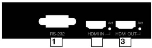

1 RS232 Port
2 HDMI Input with LED Active Signal Indicator (Lit for active)
3 Duplicate HDMI output with LED Active Signal Indicator (Lit for active)
4 EDID DIP Switch with Upgrade Switcher
5 TCP/IP Connector
6 IR TX Transmitter port
7 IR RX Receiver port
8 LED HDBT Link Indicator (Lit for active)
9 HDBT Out
10 LED 5v DC Power Indicator (Lit for powered)
11 DC 5V Power Input
5iv. EX-1UTP-IR-100-EDID Receiver
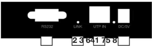

1 RS232 Port
2 LED HDBT Link Indicator (Lit for active)
3 UTP IN
4 DC 5V Power Input
5 HDMI OUT
6 TCP/IP Connector
7 IR TX Transmitter port
8 IR RX Receiver port
6. Connection & Operation
Attention: Do Not Hotplug! - Please insert and extract cables carefully with the power switched off.
Connecting and disconnecting cables while the unit is powered can damage circuitry.
1 Connect the HDMI source input (such as: Cable/Satellite receiver, Blu-ray, games console, media device etc.) to the HDMI IN port of the TRANSMITTER. Avoid excessive bending of the HDMI cable and ensure connectors are inserted firmly in all ports.
Attention: We strongly recommend using the supplied mounting brackets to secure both baluns. Sudden movement of these devices can lead to unnecessary service call outs and loss of picture/sound due to stress on connections.
2 Position the IR emitter over the infrared receiving area of the source device and fix with the adhesive backing. You may need to adjust the location of the emitter later to achieve the best results. Sometimes moving the sensor to a different area on the source facia can improve IR performance.
Insert the IR emitter 3.5mm jack into the IR TX port on the TRANSMITTER.
Tip: You can locate the infrared sensor by shining a flashlight onto the facia of most devices.
3 For two-way IR (to control the display from the source location) insert the IR receiver 3.5mm jack into the IR RX port of the TRANSMITTER. Then connect the IR emitter to the IR TX port on the RECEIVER.
4 For transmission of LAN - connect an Ethernet cable from your network router or switch to the Ethernet port on the TRANSMITTER.
5 Connect a good quality, well terminated and tested Cat5e/6 cable with RJ45 connectors from the UTP OUT port of the TRANSMITTER to the UTP IN port of the RECEIVER. Ensure connectors are pushed securely into each port and the locking pin is engaged to prevent loosening.
Attention: UTP cable must be correctly terminated to 568B standard at both ends (see diagram). Inadequate cable quality or poor RJ45 termination leads to intermittent performance and longer install times.
6 Connect your HDMI display (LED screen, Projector etc.) to the HDMI OUT of the RECEIVER using a HDMI cable.
7 To enable LAN/internet content on your display device, connect an Ethernet cable from the Ethernet port on the RECEIVER to the corresponding LAN port on your display.
8 Insert the IR receiver 3.5mm jack into the IR RX port on the RECEIVER. Attach the IR receiver to the front of your display with the adhesive backing, ensuring there is clear line of sight to the remote control being used. You may need to adjust the position of the IR Receiver to achieve best results.
7. EDID & Upgrade Switcher Instruction
| 1 | 2 | 3 | 4 | function |
| x | x | x | 0 | Normal Output |
| x | x | x | 1 | Long Cable Mode Output |
| 0 | 0 | 0 | x | Copy from the first detected sink (note1) |
| 0 | 0 | 1 | x | 1080P 3D Stereo (note2) |
| 0 | 1 | 0 | x | 1080P Stereo (note3) |
| 0 | 1 | 1 | x | 1080i Stereo (note4) |
| 1 | 0 | 0 | x | 1080P 5.1 (note5) |
| 1 | 0 | 1 | x | 1080P 7.1 (note6) |
| 1 | 1 | 0 | x | Upgrade for MCU (note7) |
| 1 | 1 | 1 | x | Upgrade for VS100TX (note8) |
1 - On
0 - Off
X - Switch position will not effect setting
Note 1: Copy EDID from detected sink to unit with DIP switch set to this position
Note 2: Set embedded 1080p-stereo 3D compatible EDID with DIP switch set to this position.
Note 3: Set embedded 1080P-stereo EDID with DIP switch set to this position.
Note 4: Set embedded 1080i-stereo EDID with DIP switch set to this position.
Note 5: Set embedded 1080P-5.1 EDID with DIP switch set to this position.
Note 6: Set embedded 1080P-7.1 EDID with DIP switch set to this position.
Note 7: Connect USB - Serial Cable to PC (not supplied) to update transmitter MCU (reserved for future use).
Note 8: Connect USB - Serial Cable to PC (not supplied) to update HDBaseT VS100 TX chip (reserved for future use).
8i. Specification (EX-1UTP-IR-100-EDID)
| Operating Temperature Range | -5 to +35°C (-41 to +95 °F) |
| Operating Humidity Range | 5 to 90 % RH (no condensation) |
| Input Video Signal | 0.5-1.0 volts p-p |
| Input DDC Signal | 5 volts p-p (TTL) |
| Video Format Supported | DTV/HDTV: 1080P/1080i/720P/576P/480P/576i/480i DVI VESA: 1280x1024/1920x1200 |
| Output Video | HDMI 1.4+HDCP (repeat the source to the sink) |
| Output Audio | Support DTS-HD, Dolby-HD (repeat the source to the sink) |
| Maximum Transmission Distance | 100m/328ft |
| Power Supply | 5VDC |
| Power Consumption | 5 Watts Max |
| Dimensions | 119mmW×105mmD×28mmH/4.69”W×4.13”H×1.10”D |
| Mass (Per Main unit) | 0.34Kg / 0.75lb (Each) |
8ii. Specification (EX-1UTP-IR-100-POH)

| Operating Temperature Range | -5 to +35°C (-41 to +95 °F) |
| Operating Humidity Range | 5 to 90 % RH (no condensation) |
| Input Video Signal | 0.5-1.0 volts p-p |
| Input DDC Signal | 5 volts p-p (TTL) |
| Video Format Supported | DTV/HDTV: 1080P/1080i/720P/576P/480P/576i/480i DVI VESA: 1280x1024/1920x1200 |
| Output Video | HDMI 1.4+HDCP (repeat the source to the sync) |
| Output Audio | Support DTS-HD, Dolby-HD (repeat the source to the sync) |
| Maximum Transmission Distance | 100m/328ft |
| Power Supply | 12VDC |
| Power Consumption | 17 Watts Max (Pairs with EX-1UTP-IR-100-POH Transmitter) |
| Dimensions | 145mmWx106mmDx29mmH/5.71"Wx4.17"Dx1.14"H (Transmitter)130mmWx106mmDx29mmH/5.11"Wx4.17"Dx1.14"H (Receiver) |
| Mass (Main unit) | 0.86kg / 1.87lbs (Each) |
NOTE: Specifications are subject to change without notice. Mass and dimensions are approximate.
9. Updating RS232 Settings on the EX-1UTP-IR-100-POH Receiver

- Carefully open the case of the EX-1UTP-IR-100-POH Receiver. On the edge of the circuit board are positioned two jumper caps to change settings from the 'Normal' position for default operation to 'Update', which allows the system to enter Firmware Update Mode

natural_image
Close-up of a green printed circuit board with electronic components and labels (no readable text or symbols beyond basic markings)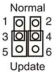
- Gently move the jumper caps to the 'Update' position to allow upgrade through the RS232 port.
- Connect USB - Serial Cable to PC and run VS100 RX Firmware Update batch file
- Once update has been completed, be sure to return the jumper caps to the 'Normal' position for RS232 control signal transmission to be passed.
Note: Connect RS232 cables to the RS232 ports of the EX-1UTP-IR-100-POH Transmitter and the Receiver to form one extension cable.
10. Typical Applications

flowchart
graph TD
    subgraph_Upper_System["EX-1UTP-IR-100-EDID TRANSMITTER"]
        A["BLU-RAY PLAYER"] --> B["INTX"]
        B --> C["R232"]
        C --> D["RIN/LRACL CABLE"]
        D --> E["HDMI PASS THROUGH"]
        E --> F["EX-1UTP-IR-100-EDID TRANSMITTER"]
        F --> G["100M/328FT CAT5E/6 CABLE"]
        G --> H["EX-1UTP-IR-100-EDID RECEIVER"]
        H --> I["HDMI OUTHDMI IN"]
        I --> J["INTX"]
        J --> K["IR RX"]
        K --> L["EX-1UTP-IR-100-EDID RECEIVER"]
        L --> M["5VDC POWER POWER IS ONLY NEED ON EX-1UTP-IR-100-EDID"]
    end

    subgraph_Lower_System["EX-1UTP-IR-100-EDID TRANSMITTER"]
        N["BLU-RAY PLAYER"] --> O["INTX"]
        O --> P["R232"]
        P --> Q["IR TX"]
        Q --> R["HDMI IN"]
        R --> S["EX-1UTP-IR-100-EDID TRANSMITTER"]
        S --> T["100M/328FT CAT5E/6 CABLE"]
        T --> U["EX-1UTP-IR-100-EDID RECEIVER"]
        U --> V["HDMI OUT"]
        V --> W["INTX"]
        W --> X["IR RX"]
        X --> Y["EX-1UTP-IR-100-EDID RECEIVER"]
        Y --> Z["5VDC POWER POWER IS ONLY NEED ON EX-1UTP-IR-100-EDID"]
    end

    style Upper_System fill:#f9f,stroke:#333
    style Lower_System fill:#bbf,stroke:#333
11. Maintenance 14. Warranty
Clean this unit with a soft, dry cloth only. Never use alcohol, paint thinner or other harsh chemicals.
12. Product Services
Provided Service:
-
Damage requiring service: This unit should be serviced by a qualified service personnel if:
-
The DC power supply or AC adaptor has been damaged.
- Objects or liquid have gotten into the unit.
- The unit has been exposed to rain.
- The unit does not operate normally or exhibits a marked change in performance.
-
The unit has been dropped or the cabinet damaged.
-
Servicing Personnel: Do not attempt to service the unit beyond that described in these operating instructions. Refer all other servicing to authorised servicing personnel.
-
Replacement Parts: When parts need replacing, ensure parts approved by the manufacturer are used – either those specified by the manufacturer or parts possessing the same characteristics as the original parts. Be aware – unauthorised substitutes may result in fire, electric shock, or other hazards and will invalidate your warranty.
-
Safety Check: After repairs or service, ask the service personnel to perform safety checks
13. Mail-in-service
When shipping the unit, carefully pack and send it prepaid, with adequate insurance and preferably in the original packaging. Please include a document or letter detailing the reason for return and include a daytime telephone number and/or email address where you can be contacted.
If repair is required during the limited warranty period, the purchaser will be required to provide a sales receipt or other proof of purchase, indicating date and location of purchase as well as the price paid for the product. The customer will be charged for the repair of any unit received unless such information is provided.
Should you feel your product does not function adequately due to defects in materials or workmanship, we (referred to as “the warrantor”) will, for the length of the period indicated below (starting from the original date of purchase) either:
a) Repair the product with new or refurbished parts. or
b) Replace it with a new or refurbished product.
Limited warranty period:
All Wyrestorm products are covered by a 2 or 3 year PARTS and LABOUR warranty. During this period there will be no charge for unit repair, replacement of unit components or replacement of product if necessary.
Please check the specific warranty period that applies to your purchased product with your Wyrestorm dealer.
The decision to repair or replace will be made by the warrantor. The purchaser must mail-in the product during the warranty period. This limited warranty only covers the product purchased as new and is extended to the original purchaser only. It is non-transferable to subsequent owners, even during the warranty period.
A purchase receipt or other proof of original purchase date is required for the limited warranty service.
15. Warranty Limits and Exclusions
- This Limited Warranty ONLY COVERS failures due to defects in materials or workmanship and DOES NOT COVER normal wear and tear or cosmetic damage.
The limited warranty also DOES NOT COVER damage that occurs in shipment or failures caused by products not supplied by the warrantor, failures resulting from accident, misuse, abuse, neglect, mishandling, misapplication, alteration, incorrect installation, set-up adjustment, implementation of/to consumer controls, improper maintenance, power line surge, lightening damage, modification, service by anyone other than a manufacturer-approved service centre or factory-authorised personnel, or damage attributable to acts of God.
- There are no express warranties except as listed under “limited warranty coverage.” The warrantor is not liable for incidental or consequential damage resulting from the use of this product or arising out of any breach of this warranty.
For example: damages for lost time, the cost of having a person/persons remove or re-install previously installed equipment, travel to and from service location, loss of or damage to media, images, data or other recorded/stored content. The items listed here are not exclusive, but are for illustration only.
Parts and service not covered by this limited warranty are not the responsibility of the warrantor and should be considered the responsibility of the individual.
16. Installation Test Notes
WyreStorm DIGITAL INTEGRITY
www.wyrestorm.com
WyreStorm Offices
US Office: 6991 Appling Farms Parkway, Suite 104, Memphis, TN 38133
Tel: +1 901 384 3575 Fax: +901 384 3574
Unit 22, Ergo Business Park, Swindon, Wiltshire, SN3 3JW UK
Tel: +44 (0) 1793 230 343 Fax: +44 (0) 1793 230 583
WyreStorm Technical Support
US: +1 866 677 0053
UK:- +44 (0) 1793 238 338
Email: support@wyrestorm.com
We reserve the right to change specification or product dimensions at any time.


- Contents 1. Introduction
- Features 3. Safety Precautions
- WARNING
- Package Contents
- EX-1UTP-IR-100-EDID
- EX-1UTP-IR-100-POH
- 5i. EX-1UTP-IR-100-POH Transmitter
- 5ii. EX-1UTP-IR-100-POH Receiver
- 5iii. EX-1UTP-IR-100-EDID Transmitter
- 5iv. EX-1UTP-IR-100-EDID Receiver
- Connection & Operation
- EDID & Upgrade Switcher Instruction
- 8i. Specification (EX-1UTP-IR-100-EDID)
- 8ii. Specification (EX-1UTP-IR-100-POH)
- Updating RS232 Settings on the EX-1UTP-IR-100-POH Receiver
- Typical Applications
- Maintenance 14. Warranty
- Product Services
- Mail-in-service
- Limited warranty period:
- Warranty Limits and Exclusions
- Installation Test Notes
- WyreStorm DIGITAL INTEGRITY
- WyreStorm Offices
- WyreStorm Technical Support
Brand : WyreStorm
Model : EX-1UTPIR100POH
Category : Audio/video extender