X410-SAS-E28 - Server EMC - Free user manual and instructions
Find the device manual for free X410-SAS-E28 EMC in PDF.

| Product Type | Server |
| Brand | EMC (Dell EMC) |
| Model | X410-SAS-E28 |
| Form Factor | 2U Rackmount |
| Dimensions (H x W x D) | 3.5 x 17.2 x 25.6 inches (approx.) |
| Weight | Approximately 55 lbs (25 kg) |
| Power Supply | Dual redundant 1100W AC power supplies |
| Processor Type | Intel Xeon Scalable (2nd/3rd Gen) |
| Memory | Up to 2TB DDR4 ECC RDIMM |
| Storage Interface | SAS 12Gb/s |
| Drive Bays | 24 x 2.5" SAS/SATA hot-swappable |
| Networking | Integrated dual-port 10GbE |
| RAID Support | Hardware RAID 0/1/10/5/6/50/60 |
| Expansion Slots | 8 x PCIe 4.0 x16 slots |
| Management | iDRAC9 with Lifecycle Controller |
| Operating Temperature | 50°F to 95°F (10°C to 35°C) |
| Maintenance | Hot-swappable fans and PSUs; tool-less access |
| Safety Certifications | UL, CE, FCC Class A |
| Spare Parts Availability | Replacement PSUs, fans, drives, and memory kits available |
| Repairability | Field-replaceable units; service manual provided by EMC |
Frequently Asked Questions - X410-SAS-E28 EMC
User questions about X410-SAS-E28 EMC
0 question about this device. Answer the ones you know or ask your own.
Ask a new question about this device
Download the instructions for your Server in PDF format for free! Find your manual X410-SAS-E28 - EMC and take your electronic device back in hand. On this page are published all the documents necessary for the use of your device. X410-SAS-E28 by EMC.
USER MANUAL X410-SAS-E28 EMC
natural_image
Abstract 3D wireframe surface with grid lines, no text or symbols presentIsilon
Site Preparation and Planning Guide
Copyright © 2015 Isilon. All rights reserved. Published in USA.
Published August, 2015
EMC believes the information in this publication is accurate as of its publication date. The information is subject to change without notice.
The information in this publication is provided as is. EMC Corporation makes no representations or warranties of any kind with respect to the information in this publication, and specifically disclaims implied warranties of merchantability or fitness for a particular purpose. Use, copying, and distribution of any EMC software described in this publication requires an applicable software license.
EMC ^2 , EMC, and the EMC logo are registered trademarks or trademarks of EMC Corporation in the United States and other countries. All other trademarks used herein are the property of their respective owners.
For the most up-to-date regulatory document for your product line, go to EMC Online Support (https://support.emc.com).
EMC Corporation
Hopkinton, Massachusetts 01748-9103
1-508-435-1000 In North America 1-866-464-7381
www.EMC.com
CHAPTER 1
Introduction to this guide
This section contains the following topics:
• About this guide....4
• Isilon scale-out NAS overview 4
• OneFS storage architecture....4
- Isilon node components....4
• Where to go for support....5
About this guide
This guide describes how to prepare and plan for your Isilon hardware installation.
Before you implement an EMC Isilon cluster into your data workflow, it is important to identify the best Isilon equipment and software for your needs. You must also confirm that your facility is ready to support your Isilon cluster.
The information in this guide provides a framework for the research that a System Administrator or Facility Manager must conduct before powering on an Isilon node.
For detailed information about the OneFS operating system, review OneFS documentation on the EMC Online Support site (https://support.emc.com).
Isilon scale-out NAS overview
The EMC Isilon scale-out NAS storage platform combines modular hardware with unified software to harness unstructured data. Powered by the OneFS operating system, an EMC Isilon cluster delivers a scalable pool of storage with a global namespace.
The platform's unified software provides centralized web-based and command-line administration to manage the following features:
• A cluster that runs a distributed file system
• Scale-out nodes that add capacity and performance
• Storage options that manage files and tiering
• Flexible data protection and high availability
• Software modules that control costs and optimize resources
OneFS storage architecture
EMC Isilon takes a scale-out approach to storage by creating a cluster of nodes that runs a distributed file system. OneFS combines the three layers of storage architecture—file system, volume manager, and data protection—into a scale-out NAS cluster.
Each node adds resources to the cluster. Because each node contains globally coherent RAM, as a cluster becomes larger, it becomes faster. Meanwhile, the file system expands dynamically and redistributes content, which eliminates the work of partitioning disks and creating volumes.
Nodes work as peers to spread data across the cluster. Segmenting and distributing data—a process known as striping—not only protects data, but also enables a user connecting to any node to take advantage of the entire cluster's performance.
OneFS uses distributed software to scale data across commodity hardware. Each node helps control data requests, boosts performance, and expands the cluster's capacity. No master device controls the cluster; no slaves invoke dependencies. Instead, each node helps control data requests, boosts performance, and expands the cluster's capacity.
Isilon node components
As a rack-mountable appliance, a storage node includes the following components in a 2U or 4U rack-mountable chassis with an LCD front panel: CPUs, RAM, NVRAM, network
interfaces, InfiniBand adapters, disk controllers, and storage media. An Isilon cluster comprises three or more nodes, up to 144.
When you add a node to a cluster, you increase the cluster's aggregate disk, cache, CPU, RAM, and network capacity. OneFS groups RAM into a single coherent cache so that a data request on a node benefits from data that is cached anywhere. NVRAM is grouped to write data with high throughput and to protect write operations from power failures. As the cluster expands, spindles and CPU combine to increase throughput, capacity, and input-output operations per second (IOPS).
EMC Isilon makes several types of nodes, all of which can be added to a cluster to balance capacity and performance with throughput or IOPS:
| Node Use | Case |
| S-Series IOPS-intensive applications | |
| X-Series High-concurrency and throughput-driven workflows | |
| NL-Series Near-primary accessibility, with near-tape value | |
| HD-Series Maximum capacity | |
The following EMC Isilon nodes improve performance:
| Node Function | |
| A-Series Performance Accelerator | Independent scaling for high performance |
| A-Series Backup Accelerator High-speed and scalable backup-and-restore solution for tape drives over Fibre Channel connections | |
Where to go for support
You can contact EMC Isilon Technical Support for any questions about EMC Isilon products.
| Online Support | Live ChatCreate a Service Request |
| Telephone Support United States: 1-800-SVC-4EMC (800-782-4362)Canada: 800-543-4782Worldwide: +1-508-497-7901For local phone numbers in your country, see EMC Customer Support Centers. | |
| Help with online support | For questions specific to EMC Online Support registration or access, email support@emc.com. |
Introduction to this guide
CHAPTER 2
Selecting your equipment
Isilon offers a variety of storage and accelerator nodes that you can combine to meet your storage needs.
If you want to install more than one type of node in your Isilon cluster, see the requirements for mixed-node clusters in the Isilon Supportability and Compatibility Guide.
Talk to an Isilon Sales Account Manager to identify the equipment best suited to support your workflow.
• Safety and EMI Compliance....8
• Storage node specifications....8
- Accelerator nodes.... 17
- Racks and rails....18
• Switches and cables 25
• Network topology....27
• Assisting with installation.... 27
Safety and EMI Compliance
This Information Technology Equipment is compliant with the electromagnetic compatibility (EMC) and product safety regulations/standards required by the countries in which the product is sold. EMC compliance is based on FCC part 15, CISPR22/CISPR24 and EN55022/EN55024 standards, including applicable international variations.
EMC compliant Class A products are marketed for use in business, industrial, and commercial environments. Product Safety compliance is based on IEC 60950-1 and EN 60951-1 standards, including applicable national deviations.
This Information Technology Equipment is in compliance with EU RoHS Directive 2011/65/EU.
The individual devices used in this product are approved under a unique regulatory model identifier that is affixed to each individual device rating label, which may differ from any marketing or product family name in this datasheet.
For additional information, visit https://support.emc.com. In the Product and Support Tools area, click Safety & EMI Compliance Information.
Storage node specifications
You can review the specifications of EMC Isilon nodes to learn node weight and dimensions, attributes, options, and industry certifications.
S210 node specifications
The Isilon S210 node is a 2U storage option in the Isilon S-Series product line. To install an Isilon S210 node, your cluster must be running OneFS 7.1.1 or later.
Dimensions and weight
| Height | Width Depth Weight | ||
| 3.48 in (8.8 cm) | 18.87 in (48 cm) | 30.5 in (77.47 cm) | 55.0 lbs (25.0 kg) |
Node attributes and options
| Attribute | 300 GB HDDs 60 | 0 GB HDDs 900 GB | 8 HDDs 1.2 TB HDDs | |
| Capacity (HDD/SSD) 6 | 6-7.2 TB / 0-1.6 TB | 13.2-14.4 TB / 0-1.6 TB | 16.2-21.6 TB / 0-4.8 TB | 21.6-28.8 TB / 0-4.8TB |
| Hard Drives (2.5" 10k RPM) | 22-24 22-24 18- | 24 18-24 | ||
| Solid State Drives (200GB) | 0-2 0-2 0-6 0-6 | |||
| System Memory 32, 64, 128, or 256 GB | ||||
| Front-end Networking | 2 copper 1000 Base-T (GE) and 2 x 10GE (SFP+ or twin-ax copper) | |||
| Drive Controller SAS-2, 6 Gb/s | ||||
| CPU Type Dual, 6-core | Intel ^ Xeon ^ processor | |||
| Attribute 300 GB HDDs | Ds 600 GB HDDs | 900 GB HDDs 1.2 | TB HDDs | |
| Infrastructure Networking | 2 InfiniBand connections supporting DDR and QDR links | |||
| Non-volatile RAM (NVRAM) | 2 GB | |||
| Typical Power Consumption @100v and @240v | 425W | |||
| Typical Thermal Rating | 1,500 BTU/hr | |||
Cluster attributes
| Number of nodes | Capacity Memory | Rack Units | |
| 3-144 16.2 TB to 4. | 15 PB 96 GB to 36.8 | TB 6-288 |
X210 node specifications
The Isilon X210 node is a 2U storage option in the Isilon X-Series product line. To install an Isilon X210 node, your cluster must be running OneFS 7.2.1 or later.
Dimensions and weight
| Height | Width Depth Weight | ||
| 3.48 in (8.8 cm) | 18.87 in (47.9 cm) | 28.5 in (72.4 cm) | 61 lbs (27.7 kg) |
Node attributes and options
| Attribute | 1 TB HDDs 2 TB | HDDs 3 TB HDDs | 4 TB HDDs | |
| Capacity 6-12 TB 12-24 | TB 18-36 TB 24-48 | TB | ||
| Hard Drives (3.5" 7200 RPM) | 6-12 6-12 6-12 6-12 | 12 | ||
| Self-Encrypting Drives (SED HDD) option (7200 RPM) | No No Yes Yes | |||
| Solid State Drives (SSDs) (200, 400, or 800 GB) | Up to 6 Up to 6 Up to 6 | Up to 6 | ||
| Self-Encrypting Drives (SED SSD) option (800 GB) | No No Yes (0, 2, or 4) | Yes (0, 2, or 4) | ||
| System ECC Memory | 24 or 48 GB | |||
| Front-end Networking | 2 x GbE and 2 x 10 GbE (SFP+ or twin-ax copper) | |||
| Network Interfaces | Isilon network interfaces support IEEE 802.3 standards for 10Gbps, 1Gbps, and 100MBps network connectivity | |||
| Attribute 1 TB HDDs 2 | TB HDDs 3 TB HDDs 4 TB HDDs | ||
| Drive Controller SATA-3, 6 Gb/s | |||
| CPU Type Intel | ® Xeon® Processor E5-2407v2, 4 core | ||
| Infrastructure Networking | 2 InfiniBand connections supporting QDR links | ||
| Non-volatile RAM (NVRAM) | 2 GB | ||
| Typical Power Consumption @100v | 400 Watts | ||
| Typical Power Consumption @240v | 400 Watts | ||
| Typical Thermal Rating 1,370 BTU/hr | |||
Cluster attributes
| Number of nodes | Capacity Memory | Rack Units | |
| 3-144 18 TB to 6.9 | PB 72 GB to 6.9 TB | 6-288 |
X410 node specifications
The Isilon X410 node is a 4U storage option in the Isilon X-Series product line. To install an Isilon X410 node, your cluster must be running OneFS 7.1.1 or later.
Dimensions and weight
| Height | Width Depth Weight | |
| 6.96 in (17.7 cm) | 18.90 in (48 cm) 28.5 in (72.4 cm) 120 | Ibs (54.5 kg) |
Node attributes and options
| Attribute | 1 TB HDDs | 2 TB HDDs 3 | TB HDDs 4 TB HDDs | |
| Capacity 32–36 TB 60–72 TB 97.6 | -108 TB 122. | 4–144 TB | ||
| Hard Drives (3.5" SATA 7200 RPM) | 32–36 30–36 | 32–36 | 30–36 | |
| Solid State Drives | 0–4 0–6 0–6 | 0–6 | ||
| Self-Encrypting Drives (SEDs) option(7200 RPM) | No | No | Yes (0, 2, 4, or 6) | Yes (0, 2, 4, or 6) |
| System Memory | 32, 64, 128, or 256 GB | |||
| Front-end Networking | 2 x Gigabit Ethernet and 2 x 10GE (SFP+ or twin-ax copper) | |||
| Drive Controller | SATA-3, 6 GB/s | |||
| CPU Type | Dual, 8-core Intel® Xeon® processor | |||
| Infrastructure Networking | 2 InfiniBand connections supporting DDR and QDR links | |||
| Attribute 1 TB HDDs 2 TB HDDs | 3 TB HDDs 4 TB HDDs | ||
| Non-volatile RAM (NVRAM) 2 GB | |||
| Typical Power Consumption @100v | 700W | ||
| Typical Power Consumption @240v | 700W | ||
| Typical Thermal Rating 2,400 BTU/hr | |||
Cluster attributes
| Number of nodes | Capacity Memory | Rack Units | |
| 3-144 108 TB to 20 | 7 PB 96 GB to 36.8 | TB 12-576 |
NL410 node specifications
The Isilon NL410 node is a 4U storage option in the Isilon NL-Series product line. To install an Isilon NL410 node, your cluster must be running OneFS 7.2.1 or later.
Dimensions and weight
| Height | Width Depth Weight | |
| 6.96 in (17.7 cm) | 18.9 in (48 cm) 31.25 in (79.4 cm) 114 lbs (51.7 kg) | |
Node attributes and options
| Attribute | 1 TB HDDs 2 | TB HDDs 3 TB H | DDs 4 TB HDDs | 6 TB HDDs | |
| Capacity 35-36 | TB 70-72 TB 10 | 5-108 TB 140 TB | -144 | TB | 210 TB |
| Hard Drives (3.5" SATA 7200 RPM) | 35 or 36 35 or | 36 35 or 36 35 or | 36 35 | ||
| Self-Encrypting Drives (SEDs) option (7200 RPM) | No No Yes Yes | No | |||
| FIPS 140-2 level 2 validated SEDs | |||||
| Solid State Drives (SSDs) (200 GB or 800 GB) | 0 or 1 (optional) | 0 or 1 (optional) | 0 or 1 (optional) | 0 or 1 (optional) | 1 (required) |
| Self-Encrypting Drives (SEDs SSD) option (800 GB) | No No No Yes No | ||||
| System ECC Memory | 24 GB or 48 GB | ||||
| Attribute 1 TB | HDDs 2 TB HDDs 3 TB HDDs | 4 TB HDDs 6 TB | HDDs | |
| Front-end Networking | 2 x GbE and 2 x 10 GbE (SFP+ or twin-ax copper) | |||
| Network Interfaces | Isilon network interfaces support IEEE 802.3 standards for 10Gbps, 1Gbps, and 100MBps network connectivity | |||
| Drive Controller | SATA-3, 6 Gb/s | |||
| CPU Type Intel | ® Xeon® Processor E5-2407v2 | |||
| Infrastructure Networking | 2 InfiniBand connections supporting QDR links | |||
| Non-volatile RAM (NVRAM) | 2 GB | |||
| Typical Power Consumption @100v | 800W | |||
| Typical Power Consumption @240v | 720W | |||
| Typical Thermal Rating | 2,500 BTU/hr | |||
Cluster attributes
| Number of nodes | Capacity Memory | Rack Units | |
| 3–144 108 TB to 30 | 2 PB 36 GB to 6.9 TB | 12–576 |
HD400 node specifications
The Isilon HD400 node is a 4U high density, deep archive storage solution.
Dimensions and weight
| Height | Width Depth Weight | ||
| 6.96 in (17.7 cm) | 18.90 in (48 cm) | 35.00 in (88.9 cm) | 220 lbs (100 kg) |
Node attributes and options
| Attribute | 6 TB HDDs |
| Capacity 354 TB | |
| Hard Drives(3.5" SATA, 7200 RPM) | 59 |
| Solid State drives(800GB) | 1 |
| Attribute 6 TB HDDs | |
| Self-Encrypting Drives (SEDs) option | No |
| OneFS Version Required | 7.2 or higher |
| System Memory 24 or 48 | GB |
| Front-end Networking 2 x | Gigabit Ethernet and 2 x 10GE (SFP+ or twin-ax copper) |
| Network interfaces Isilon | network interfaces support IEEE 802.3 standards for 10Gbps, 1Gbps, and 100Mbps network connectivity |
| Drive Controller SATA-3, | 6 Gb/s |
| CPU Type Intel | ® Xeon® Processor E5-2407 v2 (10M Cache, 2.40 GHz) |
| Infrastructure Networking | 2 InfiniBand connections with quad data rate (QDR) links |
| Non-volatile RAM (NVRAM) | 2 GB |
| Typical Power Consumption @100v | N/A |
| Typical Power Consumption @240v | 1100 Watts |
| Typical Thermal Rating 2 | 900 to 3750 BTU/hr |
Cluster attributes
| Number of nodes | Capacity Memory | Rack Units | |
| 3-144 1.06 PB to 50 | .9 PB 72 GB to 6.9 TB | 12-576 |
S200 node specifications
The Isilon S200 node is a 2U storage option in the Isilon S-Series product line.
Dimensions and weight
| Height | Width Depth Weight | |
| 3.48 in (8.8 cm) | 18.87 in (48 cm) 28.5 in (72.4 cm) 55.0 lbs (25.0 kg) | |
Node attributes and options
| Attribute | 300 GB HDDs 600 | GB HDDs 900 GB | HDDs (Requires OneFS 6.5.5 or later) | 1.2 TB HDDs (Requires OneFS 6.5.5 or later) |
| Capacity (HDD/SSD) | 5.4–7.2 TB / 0–4.8 TB | 10.8–14.4 TB / 0–4.8 TB | 16.2–21.6 TB / 0–4.8 TB | 21.6–28.8 TB / 0–4.8 TB |
| Hard Drives (2.5" 10k RPM) | 18–24 18–24 18– | 24 18–24 | ||
| Attribute 300 GB HDDs 600 GB HDDs 900 GB HDDs (Requires OneFS 6.5.5 or later) | 1.2 TB HDDs (Requires OneFS 6.5.5 or later) | |||
| Solid State Drives (200GB, 400GB, or 800GB) | 0-6 0-6 0-6 0-6 | |||
| System Memory 24, 48, or 96 GB | ||||
| Front-end Networking | 4 copper 1000 Base-T (GigE) or 4 x GigE (copper) or 2 x GigE and 2 x 10GigE (SFP+ or twin-ax copper) | 4 copper 1000 Base-T (GigE) or 4 x GigE (copper) or 2 x GigE and 2 x 10GigE (SFP+ or twin-ax copper) | 2 x GigE and 2 x 10GigE (SFP+) | 2 x GigE and 2 x 10GigE (SFP+) |
| Drive Controller SAS-2, 6 Gb/s | ||||
| CPU Type Dual, 4-core Intel ® Xeon® Processor | ||||
| Infrastructure Networking | 2 InfiniBand connections supporting DDR links | |||
| Non-volatile RAM (NVRAM) | 512 MB | |||
| Typical Power Consumption @100v and @240v | 450W | |||
| Typical Thermal Rating | 1,550 BTU/hr | |||
Cluster attributes
| Number of nodes | Capacity Memory | Rack Units | |
| 3-144 16.2 TB to 4. | 15 PB 72 GB to 13.8 | TB 6-288 |
X200 node specifications
The Isilon X200 node is a 2U storage option in the Isilon X-Series product line.
Dimensions and weight
| Height | Width Depth Weight | |
| 3.48 in (8.8 cm) | 18.87 in (48 cm) 28.5 in (72.4 cm) 61 | lbs (27.7 kg) |
Node attributes and options
| Attribute | 1 TB HDDs 2 TB HDDs 3 TB HDDs | |
| Capacity 7.2–12 TB 13.2–24 TB 19.2–36 TB |
| Attribute 1 TB HDDs 2 TB HDDs 3 TB HDDs | |||
| Hard Drives (3.5" 7200 RPM) 6–12 6– | 12 6–12 | ||
| Solid State Drives (200GB or 800GB) | Up to 6 Up to 6 Up to 6 | ||
| Self-Encrypting Drives (SED HDD) option(7200 RPM) | No No Yes | ||
| Self-Encrypting Drives (SED SSD) option(800GB) | No No Yes (0, 2, or 4) | ||
| System Memory 6, 12, 24, or 48 GB | |||
| Front-end Networking 4 x GigE or 2 x GigE and 2 x 10GigE (SFP+ or twin-ax copper) | |||
| Drive Controller SATA-3, 6 Gb/s | |||
| CPU Type Intel | ® Xeon® Processor | ||
| Infrastructure Networking 2 InfiniBand | connections with double data rate (DDR) links. | ||
| Non-volatile RAM (NVRAM) 512 MB | |||
| Typical Power Consumption@100v and @240v | 400W | ||
| Typical Thermal Rating 1,370 BTU/hr | |||
Cluster attributes
| Number of nodes | Capacity Memory Rack Units | |
| 3-144 | 24 TB to 5.2 PB 18 GB to 6.9 TB 6 | -288 |
X400 node specifications
The Isilon X400 node is a 4U storage option in the Isilon X-Series product line.
Dimensions and weight
| Height | Width | Depth | Weight |
| 6.96 in (17.7 cm) | 18.90 in (48 cm) | 31.25 in (79.4 cm) | 127 lbs (57.7 kg) |
Node attributes and options
| Attribute | 1 TB HDDs | 2 TB HDDs | 3 TB HDDs | 4 TB HDDs |
| Capacity | 33.6–36 TB | 67.2–72 TB | 97.6–108 TB | 122.4–144 TB |
| Hard Drives (3.5" SATA) | 32–36 | 33–36 | 32–36 | 30–36 |
| Solid State Drives | 0, 2, or 4 | 0 or 3 | 0 or 4 | 0 or 6 |
| Self-Encrypting Drives (SEDs) option (7200 RPM) | No | No | YesFIPS 140-2 level 2 validated SEDs with unique AES-256 bit | No |
| Attribute 1 TB HDDs 2 | TB HDDs 3 | TB HDDs 4 | TB HDDs | |
| strength keys assigned to each drive. | ||||
| System Memory 24, 48, | 96, or 192 GB | |||
| Front-end Networking 4 | x GigE or 2 x GigE and 2 x 10 GigE (SFP+ or twin-ax copper)4 TB HDDs: 4 x GigE or 2 x GigE and 2 x 10GigE (SFP+) | |||
| Network Interface Isilon | network interfaces support IEEE 802.3 standards for 10Gps, 1Gps, and 100Mbps network connectivity | |||
| Drive Controller SATA-3, | 6 GB/s | |||
| CPU Type Dual, 6-core Intel ® Xeon® Processor | ||||
| Infrastructure Networking | 2 InfiniBand connections with double data rate (DDR) links. | |||
| Non-volatile RAM (NVRAM) | 512 MB | |||
| Typical Power Consumption @100v and @240v | 725W | |||
| Typical Thermal Rating 2,500 BTU/hr | ||||
Cluster attributes
| Number of nodes | Capacity Memory | Rack Units | |
| 3-144 108 TB to 20 | 7 PB 72 GB to 27.6 | TB 12-576 |
NL400 node specifications
The Isilon NL400 node is a 4U storage option in the Isilon NL-Series product line.
Dimensions and weight
| Height | Width Depth Weight | ||
| 6.96 in (17.7 cm) | 18.90 in (48 cm) 31 | 1.25 in (79.4 cm) 127 | lbs (57.7 kg) |
Node attributes and options
| Attribute | 1 TB HDDs | 2 TB HDDs 3 | TB HDDs 4 TB HDDs | |
| Capacity 36 TB 72 TB | 108 TB | 144 TB | ||
| Hard Drives (3.5" SATA) | 36 | 36 | 36 | 36 |
| Self-Encrypting Drives (SEDs) option (7200 RPM) | No | No | YesFIPS 140-2 level 2 validated SEDs with unique AES-256 bit strength keys assigned to each drive. | No |
| System Memory | 12, 24, or 48 GB | |||
| Attribute 1 TB HDDs 2 TB | TB HDDs 3 TB | HDDs 4 TB | HDDs | |
| Front-end Networking 4 x GigE or 2 x GigE and 2 x 10 GigE (SFP+ or twin-ax copper) | ||||
| Network Interface Isilon network interfaces support IEEE 802.3 standards for 10Gps, 1Gps, and 100Mbps network connectivity | ||||
| Drive Controller SATA-3, 6 GB/s | ||||
| CPU Type Intel | ® Xeon® Processor | |||
| Infrastructure Networking | 2 InfiniBand connections with double data rate (DDR). | |||
| Non-volatile RAM (NVRAM) | 512 MB | |||
| Typical Power Consumption @100v and @240v | 725W | |||
| Typical Thermal Rating 2,500 BTU/hr | ||||
Cluster attributes
| Number of nodes | Capacity Memory | Rack Units | |
| 3-144 108 TB to 20 | 7 PB 72 GB to 27.6 | TB 12-576 |
Accelerator nodes
With Isilon accelerators, you can scale the performance of your cluster without increasing capacity.
A100 accelerator specifications
The Isilon A100 performance accelerator reduces latency and increases throughput for clusters supporting demanding applications and workloads. The backup accelerator scales performance for tape backup, disaster recovery, compliance, and archiving.
Dimensions and Weight
| Height | Width Depth Weight | ||
| 1.72 in (4.4 cm) | 18.87 in (47.9 cm) | 28.6 in (72.6 cm) | 30 lbs (13.6 kg) |
Node attributes
| Attribute | A100 backup accelerator | A100 performance accelerator |
| Front-end Networking 8 GB F | bre Channel x 4 10 GigE x 2 (Fibre or Copper)1 GigE x 4 (Copper) | |
| Memory 16 GB | 256 GB | |
| CPU Type | Intel® Xeon® Processor2 GHz x 2 | |
| Attribute A100 backup accelerator A100 performance accelerator | |
| Infrastructure Networking 2 QDR InfiniBand connections | |
| AC Power Input 100–240 VAC, 60–50 Hz, auto-ranging | |
| Typical Power Consumption @100v and @240v | 300W |
| Typical Thermal Rating 1,030 BTU/hr | |
A100 guidelines
Follow these guidelines to get optimal performance from your A100 accelerator node.
The A100 accelerator provides the most benefit to workflows where it can:
• magnify cached read performance.
• expand physical GigE network ports.
• increase high single-stream throughput.
• enhance a 10 GigE network interface.
• reduce latency on cached, read-intensive workflows.
To make sure that your A100 accelerator is running in an optimal environment, also discuss the version of OneFS you are running with your EMC Isilon Account Team.
The A100 will not provide significant performance improvements in workflows that include:
• uncached concurrent reads.
• concurrent writes.
- high 1Ops.
With these types of workflows it is best to consider additional storage nodes to improve performance.
Racks and rails
You can secure your Isilon nodes to standard storage racks with a sliding rail system.
Rail kits are included in all node packaging and are compatible with racks with the following types of holes:
• 3/8 inch square holes
• 9/32 inch round holes
• 10-32, 12-24, M5X.8, or M6X1 pre-threaded holes
Rail kit mounting brackets adjust in length from 24 inches to 36 inches to accommodate different rack depths. When you select a rack for your Isilon nodes, ensure that the rack supports the minimum and maximum rail kit sizes.
You can mount all Isilon nodes in standard ANSI/EIA RS310D 19-inch rack systems.
EMC 40U-P Titan rack
The EMC 40U-P Titan rack supports all Isilon nodes. You can order the Titan rack from Isilon.
Ensure that your facility can accommodate the rack, including:
• delivery package dimensions
• installed clearance requirements
• AC power input parameters
You can also secure your rack with optional stabilizer brackets.
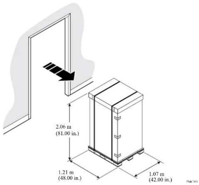
Delivery dimensions
You must ensure that your doorways and elevators can accommodate the shipping pallet and cabinet.
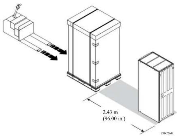
Use a mechanical lift or pallet jack to position the packaged cabinet in its final location.
Leave approximately 2.43 meters (8 feet) of clearance at the back of the cabinet to unload the unit and roll it off the pallet.
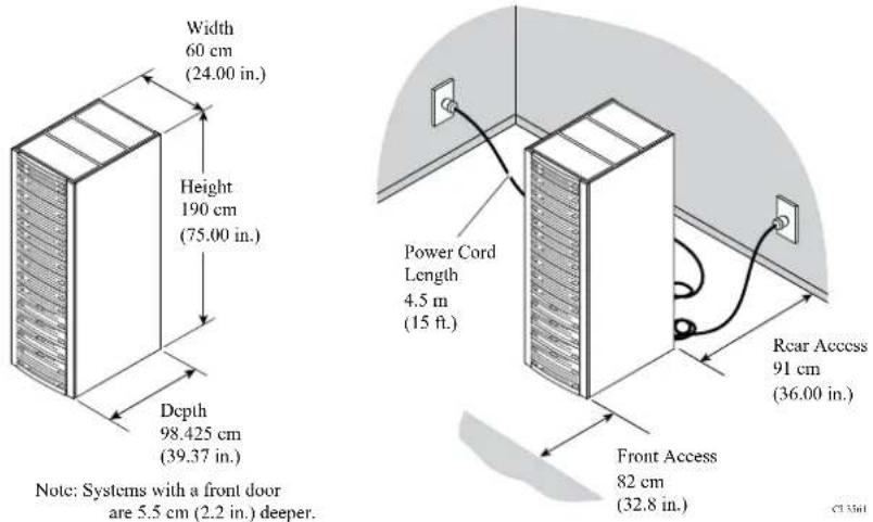
Installed clearance
The EMC 40U-P Titan rack cabinet ventilates from front to back. You must provide adequate clearance to service and cool the system.
Depending upon component-specific connections within the cabinet, the available power cord length may be somewhat shorter than the 15 foot (4.5 meter) standard.
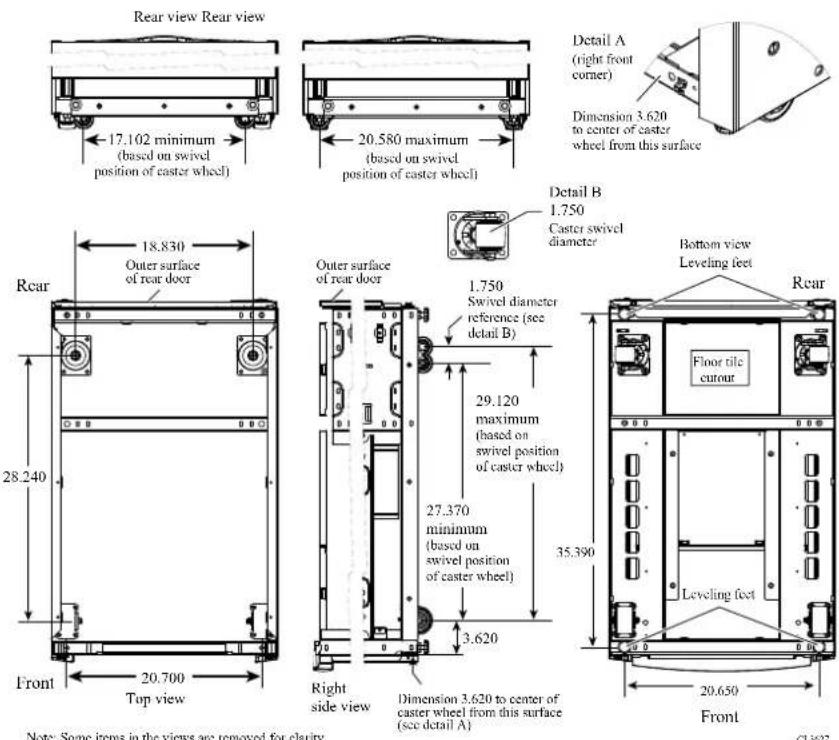
Caster wheels
The bottom of the EMC 40U-P Titan rack cabinet includes four caster wheels.
Of the four wheels on the bottom of the 40U-P rack, the two front wheels are fixed, and the two rear casters swivel in a 1.75 inch (4.45 centimeter) diameter. The swivel position of the caster wheels will determine the load-bearing points on your site floor, but does not affect the cabinet footprint. After you position, level, and stabilize the cabinet, the four leveling feet determine the final load-bearing points on your site floor.
WARNING
The data center floor on which you will configure the EMC system must be capable of supporting that system. It is your responsibility to ensure that data center floor can support the weight of the EMC system, whether the system is configured directly on the data center floor, or on a raised floor supported by the data center floor. Failure to comply with these floor-loading requirements could result in severe damage to the EMC system, the raised floor, subfloor, site floor and the surrounding infrastructure.
Notwithstanding anything to the contrary in any agreement between EMC and customer, EMC fully disclaims any and all liability for any damage or injury resulting from customer's failure to ensure that the raised floor, subfloor, and/or site floor are capable of supporting the system weight as specified in this guide. The customer assumes all risk and liability associated with such failure.
Stabilizer brackets
Optional brackets help to prevent your rack from tipping during maintenance or minor seismic events.
If you intend to secure the optional stabilizer brackets to your site floor, prepare the location for the mounting bolts.
Anti-tip bracket
You can install an anti-tip bracket to provide an extra measure of security. You can use one or two kits. For cabinets with components that slide, Isilon recommends that you install two kits.
Anti-move bracket
You can install an anti-move bracket to permanently fasten the unit to the floor.
Seismic restraint bracket
You can install a seismic restraint bracket to provide the highest protection from moving or tipping.
Shock and vibration
EMC hardware enclosures have been tested to withstand shock and random vibration.
The response measurement levels apply to all three axes. Measure shock and vibration with an accelerometer on the equipment enclosure within the cabinet. The measurements should not exceed the levels in the following table.
| Platform condition Response measurement level | |
| Non-operational shock 10 G's, 7 ms duration | |
| Operational shock 3 G's, 11 ms duration | |
| Non-operational random vibration .40 Grms, 5-500Hz, 30 minutes | |
| Operational random vibration .21 Grms, 5-500Hz, 10 minutes |
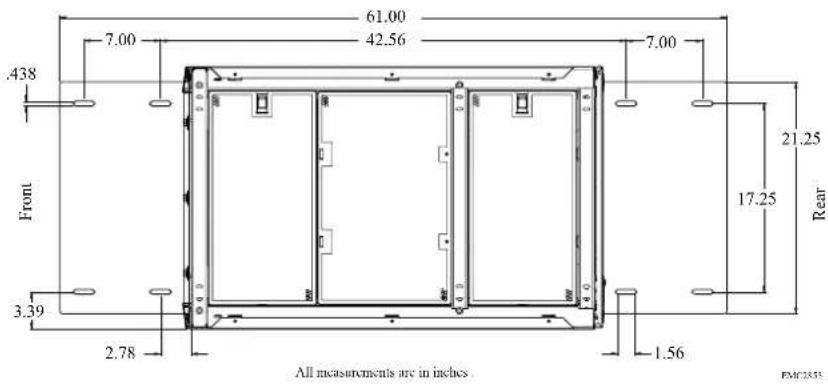
AC power input
After you position and load your EMC 40U-P Titan rack, you can connect power cords to P1 and P2 connectors on the four power distribution units (PDU) within the cabinet.
Depending on the cabinet components and configuration, the 40U-P rack requires two, four, or six independent 200-240 V power sources. Power cords included with your shipment support the maximum configurations. There might be extra cords as part of your shipment.
CAUTION
40U-P cabinet PDUs do not include a power ON/OFF switch. Ensure the four circuit breaker switches on each PDU are up, in the off position, until you are ready to supply AC power to the unit.
Also, ensure power is off before disconnecting jumper or power cords from a PDU.
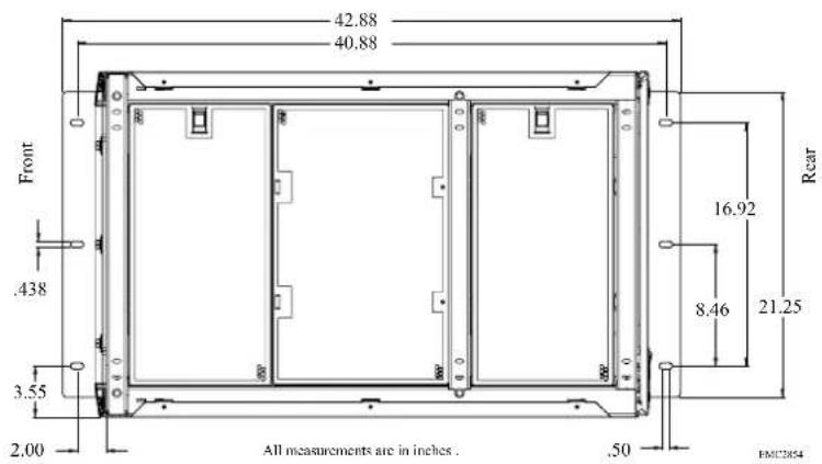
Attach power cords to the power distribution units on each side of your rack. The following image shows where to attach two AC source connections.
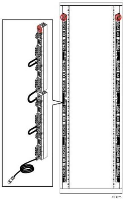
natural_image
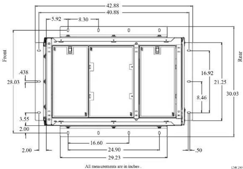
Diagram of a server rack with connected cables and connectors, showing front and side views (no text or symbols)The following image shows where to attach four AC source connections.
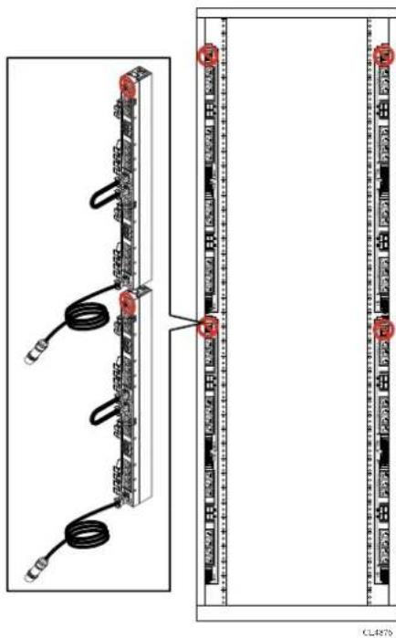
natural_image
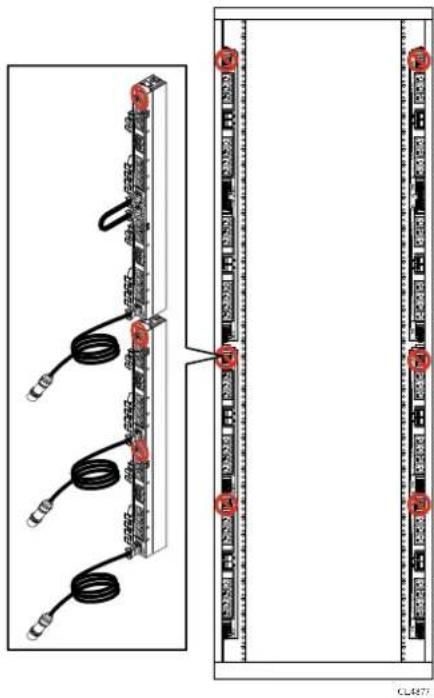
Diagram of server rack connections showing cable routing and terminal layout (no text or labels)The following image shows where to attach six AC source connections.
Switches and cables
Select network switches and cables that are compatible with your Isilon nodes and that support your network topology.
Isilon nodes use standard copper Gigabit Ethernet (GigE) switches for the front-end (external) traffic and InfiniBand for the back-end (internal) traffic.
Only InfiniBand cables and switches supplied by EMC Isilon are supported.
For a complete list of qualified switches and cables, see the Isilon Supportability and Compatibility Guide.
If you choose not to use an Isilon-recommended switch, you must use a switch that meets the following minimum specifications:
- GigE support
• Non-blocking fabric switch
• Minimum of 1 MB per port of packet buffer memory
• Support for jumbo frames (if you intend to use this feature)
CAUTION
Isilon requires that separate switches are used for the external and internal interfaces. Using a switch that has not been qualified by Isilon may result in unpredictable cluster behavior.
Cable management
Organize cables to protect the integrity of your connections, allow proper airflow around your cluster, and ensure fault-free maintenance of your Isilon nodes.
Protect cables
Damage to your InfiniBand or Ethernet cables can affect the performance of your Isilon cluster.
- Never bend cables beyond their recommended bend radius. The following table provides general guidelines for maximum bend radius, but you should consult the recommendation of your cable manufacturer.
| Cable type | Bend radius |
| InfiniBand 5 | inch (127 mm) |
| Cat 5 Four times the diameter of the cable. | |
- Keep cables away from sharp edges or metal corners.
- When bundling cables, do not pinch or constrict the cables.
- Avoid using zip ties to bundle cables. Instead, employ velcro hook-and-loop ties that do not have hard edges and you do not need to remove by cutting.
- Never bundle network cables with power cables. If network and power cables are not bundled separately, electromagnetic interference (EMI) can affect your data stream.
• If you are using overhead cable supports:
■ Ensure that your supports are anchored adequately to withstand the significant weight of bundled cables.
- Do not let cables sag through gaps in your supports. Gravity can stretch and damage cables over time.
- Place drop points in your supports that allow cables to reach racks without bending or pulling.
- If you are running cable from overhead supports or from underneath a raised floor, be sure to include vertical distances when calculating necessary cable lengths.
Ensure airflow
Bundled cables can obstruct the movement of conditioned air around your cluster.
- Secure cables away from fans.
- Employ flooring seals or grommets to keep conditioned air from escaping through cable holes.
Prepare for maintenance
Design your cable infrastructure to accommodate future work on the cluster. Think ahead to tasks that will be performed on the cluster such as locating specific pathways or connections, isolating a network fault, or adding and removing nodes and switches.
- Color code your cables to quickly identify types or functions of cables in your cluster. You can purchase colored cables or apply colored tags.
- Label both ends of every cable to denote the node or switch it should connect to.
- Leave a service loop of cable behind nodes. Service technicians should be able to slide a node out of the rack without pulling on power or network connections.
- Allow for future expansion without the need for tearing down portions of your cluster.
Network topology
External networks connect the cluster to the outside world.
You can use subnets in external networks to manage connections more efficiently. How you specify your external network subnets depends on the topology of your network.
In a basic network topology in which each node communicates to clients on the same subnet, only one external subnet is required.
A more complex topology requires several different external network subnets. For example, suppose you have a network topology in which some nodes connect to one external IP subnet, some nodes connect to a second IP subnet, and some nodes do not connect externally at all. Your network would require several different subnets.
Note
You must initially configure the default external IP subnet using IPv4.
External networks provide communication outside the cluster. OneFS supports network subnets, IP address pools, and network provisioning rules to facilitate the configuration of external networks.
The internal network supports communication among the nodes that form a cluster and is intentionally separate from the external, front-end network. The internal network is InfiniBand-based.
To configure your cluster, you must set up an initial network. You can optionally set up an alternate interface as a failover network. The Internal-A port (int-a) is the initial network. Configuration of Internal-A is required for proper operation of the cluster. The Internal-B port (int-b) is the alternate interface for internal communications and can also be used for failover.
The Internal-A Port
When setting up your cluster, you must connect the Internal-A port of each node to the switch that supports the Internal-A segment of the internal network.
The Internal-B Failover Port
You can optionally configure an Internal-B/failover network to provide the cluster with continued internal communications in the event of a faulty switch or other networking infrastructure failure.
Assisting with installation
EMC Isilon Professional Services can help you plan a cluster that best supports your workflow. Contact your Isilon Account Manager for more information.
Installation and implementation details
Three to four weeks prior to your installation date, the EMC Isilon Professional Services team will help you gather the information necessary to configure your Isilon cluster.
Your EMC Isilon project team will help you complete the Configuration Guide worksheet, which documents technical details that will be needed for the installation and implementation of your Isilon cluster.
Be prepared to discuss the following information with your EMC Isilon project team:
- Data workflow, including the role of the cluster in that workflow: production, test, or disaster recovery.
• OneFS version to install on the cluster.
- Network connectivity details, including IP ranges, for your client and InfiniBand networks.
• DNS configuration details, including name servers and search lists.
- Directory services such as Active Directory, LDAP, NIS, or local user groups.
- File sharing protocols such as SMB and NFS, and advanced file sharing options such as FTP and HTTP.
• Data protection levels, antivirus solutions, and NDMP backup.
- Cluster alert solutions such as SupportIQ and SNMP monitoring.
CHAPTER 3
Adding functionality to your cluster
You can access advanced cluster features through OneFS software modules.
To enable a OneFS module after your cluster is installed, you must activate a license by entering a license key into OneFS. Each optional OneFS software module requires you to activate a separate license.
For more information about features offered through optional software modules, see the OneFS Web Administration Guide or the OneFS CLI Administration Guide, or contact your EMC Isilon sales representative.
• Data management modules....30
• Data protection modules....32
Data management modules
Isilon offers software modules that add advanced data management features to your cluster.
You can install advanced data management modules to optimize storage performance.
SmartPools
The SmartPools module groups nodes and files into pools.
By default, OneFS provisions node pools and creates one file pool. When you activate a SmartPools license, you receive more features. You can, for example, create multiple file pools and govern them with policies. The policies move files, directories, and file pools among node pools or tiers. You can also define how OneFS handles write operations when a node pool or tier is full.
The following table compares storage pool features based on whether a SmartPools license is active.
| Feature Inactive Active | ||
| Automatic storage pool provisioning | Yes Yes | |
| Directed spillover No Yes | ||
| Policy-based data movement No Yes | ||
| Virtual hot spare Yes Yes |
SmartQuotas
The SmartQuotas module is a quota-management tool that monitors and enforces administrator-defined storage limits.
Through the use of accounting and enforcement quota limits, reporting capabilities, and automated notifications, you can manage and monitor storage utilization, monitor disk storage, and issue alerts when storage limits are exceeded.
A storage quota defines the boundaries of storage capacity that are allowed for a group, a user, or a directory on an Isilon cluster. The SmartQuotas module can provision, monitor, and report disk-storage usage and can send automated notifications when storage limits are approached or exceeded. SmartQuotas also provides flexible reporting options that can help you analyze data usage.
SmartDedupe
The SmartDedupe software module enables you to save storage space on your cluster by reducing redundant data. Deduplication maximizes the efficiency of your cluster by decreasing the amount of storage required to store multiple files with similar blocks.
SmartDedupe deduplicates data by scanning an Isilon cluster for identical data blocks. Each block is 8 KB. If SmartDedupe finds duplicate blocks, SmartDedupe moves a single copy of the blocks to a hidden file called a shadow store. SmartDedupe then deletes the duplicate blocks from the original files and replaces the blocks with pointers to the shadow store.
Deduplication is applied at the directory level, targeting all files and directories underneath one or more root directories. You can first assess a directory for
deduplication and determine the estimated amount of space you can expect to save. You can then decide whether to deduplicate the directory. After you begin deduplicating a directory, you can monitor how much space is saved by deduplication in real time.
You can deduplicate data only if you activate a SmartDedupe license on a cluster. However, you can assess deduplication savings without activating a SmartDedupe license.
InsightIQ
The InsightIQ module provides advanced monitoring and reporting tools to help you streamline and forecast cluster operations.
InsightIQ helps you create customized reports containing key cluster performance indicators such as:
• Network traffic on a per-interface, per-node, per-client, and per-protocol basis.
- Protocol operation rates and latencies that are recorded on a per-protocol, per-client, and per-operation class basis.
• Per-node CPU utilization and disk throughput statistics.
To run the Isilon InsightIQ virtual appliance, your environment must meet the following minimum system requirements.
Isilon cluster
The monitored cluster must be running version 5.5.3 or later of the Isilon OneFS operating system. The InsightIQ File System Analytics functionality requires OneFS 6.0 or later. The available InsightIQ features depend on the OneFS version that the monitored system is running.
For monitored clusters running OneFS 7.0 and later, you must enable HTTPS port 8080. For monitored clusters running an earlier version of OneFS, you must enable HTTPS port 9443. If you use the File System Analytics feature, you must also enable the NFS service, HTTPS port 111, and HTTPS port 2049 on all monitored clusters.
InsightIQ product license
Before installing the InsightIQ virtual appliance, you must obtain an InsightIQ license key for each cluster that you want to monitor. For more information, contact your EMC Isilon sales representative. After you obtain the license keys, you must activate licenses on each cluster that you want to monitor.
Web browser
You can access the Isilon InsightIQ application through any web browser that supports sophisticated graphics. Examples of supported browsers include Microsoft Internet Explorer 9, Mozilla Firefox, Apple Safari 5, and Google Chrome.
To access the InsightIQ application through Internet Explorer, you must first install the Google Chrome Frame plug-in. If InsightIQ cannot detect the plug-in, an installation prompt appears the first time that you attempt to access InsightIQ through Internet Explorer.
The InsightIQ web application interface is optimized for a screen that is 1,280 pixels wide.
Storage space for the InsightIQ datastore
InsightIQ can store monitored-cluster data either locally or on an NFS-mounted server. If InsightIQ is installed as a virtual appliance, InsightIQ by default stores the monitored-cluster data locally on a virtual hard drive that is included with the InsightIQ virtual appliance. If you want to use this local virtual hard drive as the InsightIQ datastore, ensure that the virtualization host contains at least 70 GB of free disk space. If InsightIQ is installed as an RPM, InsightIQ stores data on the local machine by default. If you store InsightIQ data on the local machine, ensure that the machine contains at least 64 GB of free disk space.
As an alternative to storing InsightIQ data locally, you can configure InsightIQ to store monitored-cluster data on an Isilon cluster—either the monitored cluster itself or a different cluster—or on any NFS-mounted server. If you want to store InsightIQ monitored-cluster data on an Isilon cluster or other NFS-based server, you must provide adequate space in which to store the data. You must also verify that an NFS export rule is properly configured on the cluster or NFS-based server. For information about NFS datastore requirements, see the InsightIQ Installation Guide.
Data protection modules
Isilon offers software modules that add advanced data protection features to your cluster.
You can install advanced data protection modules to enable enhanced replication, restoration, dynamic cluster load balancing, and technical support.
SnapshotIQ
The SnapshotIQ module allows you to create and manage snapshots on your Isilon cluster.
A snapshot contains a directory on a cluster, and includes all data that is stored in the given directory and its subdirectories. If data contained in a snapshot is modified, the snapshot stores a physical copy of the original data and references the copied data. Snapshots are created according to user specifications, or they are automatically generated by OneFS to facilitate system operations.
To create and manage snapshots, you must activate a SnapshotIQ license on the cluster. Some applications must generate snapshots to function, but do not require you to activate a SnapshotIQ license; by default, these snapshots are automatically deleted when the system no longer needs them. However, some applications allow you to retain these snapshots if a SnapshotIQ license is active on the cluster. You can view auto-generated snapshots regardless of whether a SnapshotIQ license is active.
The following table lists the available snapshot functionality depending on whether a SnapshotIQ license is active.
| Functionality | Inactive Active | |
| Create snapshots and snapshot schedules | No Yes | |
| Configure SnapshotIQ settings | No Yes | |
| View snapshot schedules Yes | Yes | |
| Delete snapshots Yes Yes | ||
| Access snapshot data Yes Yes | ||
| Functionality Inactive Active | ||
| View snapshots Yes Yes |
SyncIQ
The SynclQ module enables you to replicate data from one Isilon cluster to another.
With SyncIQ, you can replicate data at the directory level while optionally excluding specific files and sub-directories from being replicated. SyncIQ creates and references snapshots to replicate a consistent point-in-time image of a root directory. Metadata such as access control lists (ACLs) and alternate data streams (ADS) are replicated along with data.
SyncIQ enables you to retain a consistent backup copy of your data on another Isilon cluster. SyncIQ offers automated failover and failback capabilities that enable you to continue operations on another Isilon cluster if a primary cluster becomes unavailable.
SmartLock
The SmartLock module allows you to prevent users from modifying and deleting files on protected directories.
Use the SmartLock tool to create SmartLock directories and commit files within those directories to a write once, read many (WORM) state. You cannot erase or re-write a file that is committed to a WORM state. You can delete a file that has been removed from a WORM state, but you cannot modify a file that has ever been committed to a WORM state.
Note the following SmartLock considerations:
- Create files outside of SmartLock directories and transfer them into a SmartLock directory only after you finish working with the files. Upload files to a cluster in two steps.
- Upload the files into a non-SmartLock directory.
- Transfer the files to a SmartLock directory.
Note
Files committed to a WORM state while being uploaded will become trapped in an inconsistent state.
Files can be committed to a WORM state while they are still open. If you specify an autocommit time period for a directory, the autocommit time period is calculated according to the length of time since the file was last modified, not when the file was closed. If you delay writing to an open file for more than the autocommit time period, the file will be committed to a WORM state the next time you attempt to write to it.
- In a Microsoft Windows environment, if you commit a file to a WORM state, you can no longer modify the hidden or archive attributes of the file. Any attempt to modify the hidden or archive attributes of a WORM committed file will generate an error. This can prevent third-party applications from modifying the hidden or archive attributes.
SmartLock compliance mode
SmartLock compliance mode enables you to protect your data in compliance with the regulations defined by U.S. Securities and Exchange Commission rule 17a-4.
You can upgrade a cluster to SmartLock compliance mode during the initial cluster configuration process, before you activate a SmartLock license. To upgrade a cluster to
SmartLock compliance mode after the initial cluster configuration process, contact Isilon Technical Support.
If you set a cluster to compliance mode, you will not be able to log in to that cluster through the root user account. Instead, you can log in to the cluster through the compliance administrator account. You must configure the compliance administrator account during the initial cluster configuration process. If you are logged in through the compliance administrator account, you can perform administrative tasks through the sudo command.
Note
Compliance mode is not compatible with Isilon for vCenter, VMware vSphere API for Storage Awareness (VASA), or the vSphere API for Array Integration (VAAI) NAS Plug-In for Isilon.
SmartConnect Advanced
The SmartConnect Advanced module adds enhanced balancing policies to evenly distribute CPU usage, client connections, or throughput.
If you activate a SmartConnect Advanced license, you are also able to:
- Enable dynamic IP allocation and IP failover in your cluster.
- Define IP address pools to support multiple DNS zones in a subnet.
- Establish multiple pools for a single subnet.
SupportIQ
The SupportIQ module allows Isilon Technical Support, with your permission, to securely upload and analyze your OneFS logs to troubleshoot cluster problems.
When SupportIQ is enabled, Isilon Technical Support personnel can request logs through scripts that gather cluster data and then upload the data to a secure location. You must enable and configure the SupportIQ module before SupportIQ can run scripts to gather data.
You can also enable remote access, which allows Isilon Technical Support personnel to troubleshoot your cluster remotely and run additional data-gathering scripts. Remote access is disabled by default. To enable remote SSH access to your cluster, you must provide the cluster password to a Technical Support engineer.
Antivirus planning
You can scan the OneFS file system for computer viruses and other security threats by integrating with third-party scanning services through the Internet Content Adaptation Protocol (ICAP). This feature does not require you to activate a license.
If an ICAP server detects a threat it notifies OneFS. OneFS creates an event to inform system administrators, displays near real-time summary information, and documents the threat in an antivirus scan report. You can configure OneFS to request that ICAP servers attempt to repair infected files. You can also configure OneFS to protect users against potentially dangerous files by truncating or quarantining infected files.
ICAP servers
The number of ICAP servers that are required to support an Isilon cluster depends on how virus scanning is configured, the amount of data a cluster processes, and the processing power of the ICAP servers.
If you intend to scan files exclusively through antivirus scan policies, it is recommended that you have a minimum of two ICAP servers per cluster. If you intend to scan files on access, it is recommended that you have at least one ICAP server for each node in the cluster.
If you configure more than one ICAP server for a cluster, it is important to ensure that the processing power of each ICAP server is relatively equal. OneFS distributes files to the ICAP servers on a rotating basis, regardless of the processing power of the ICAP servers. If one server is significantly more powerful than another, OneFS does not send more files to the more powerful server.
Supported ICAP servers
OneFS supports ICAP servers running the following antivirus scanning software:
• Symantec Scan Engine 5.2 and later.
• Trend Micro Interscan Web Security Suite 3.1 and later.
• Kaspersky Anti-Virus for Proxy Server 5.5 and later.
- McAfee VirusScan Enterprise 8.7 and later with VirusScan Enterprise for Storage 1.0 and later.
Adding functionality to your cluster
CHAPTER 4
Preparing your facility
Preparing and maintaining an optimal data center environment is essential to ensuring the long-term health of your Isilon equipment.
• Environmental requirements.... 38
• Power requirements....40
- Fire suppressant disclaimer....42
Environmental requirements
Prepare your site to support the recommended operating parameters of Isilon equipment.
| [CBAA] | +15°C to +32°C (59°F to 89.6°F) site temperature. A fully configured cabinet can produce up to 16,400 BTUs per hour. |
 | 40% to 55% relative humidity* |
 | A fully configured cabinet sits on at least two floor tiles, and can weigh approximately 1,182 kilograms (2600 pounds). |
| [8YKB] | 0 to 2439 meters (0 to 8,000 feet) above sea level operating altitude |
 | LAN and telephone connections for remote service and system operation |
Your Isilon cluster may be qualified to operate outside these limits. Refer to the product-specific documentation for system specifications.
Air quality requirements
EMC products are designed to be consistent with the air quality requirements and thermal guidelines of the American Society of Heating, Refrigeration and Air Conditioning Engineers (ASHRAE).
For specifics, see the ASHRAE Environmental Standard Handbook and the most current revision of Thermal Guidelines for Data Processing Environments, Second Edition, ASHRAE 2009b.
Most products are best suited for Class 1 datacom environments, which consist of tightly controlled environmental parameters including temperature, dew point, relative humidity and air quality. These facilities house mission-critical equipment and are typically fault-tolerant, including the air conditioners.
The data center should maintain a cleanliness level as identified in ISO 14664-1, class 8 for particulate dust and pollution control. The air entering the data center should be filtered with a MERV 11 filter or better. The air within the data center should be continuously filtered with a MERV 8 or better filtration system. Take measures to prevent conductive particles such as zinc whiskers from entering the facility.
The allowable relative humidity level is 20% to 80% non condensing. However, the recommended operating environment range is 40% to 55%. Lower temperatures and humidity minimize the risk of hardware corrosion and degradation, especially in data
centers with gaseous contamination such as high sulfur content. Minimize humidity fluctuations within the data center. Prevent outside air contaminants and humidity from entering the facility by positively pressurizing the data center and installing air curtains on entryways.
For facilities below 40% relative humidity, use grounding straps when contacting the equipment to avoid the risk of Electrostatic discharge (ESD), which can harm electronic equipment.
As part of an ongoing monitoring process for the corrosiveness of the environment, place copper and silver coupons (per ISA 71.04-1985, Section 6.1 Reactivity) in airstreams representative of those in the data center. The monthly reactivity rate of the coupons should be less than 300 Angstroms. If the monitored reactivity rate exceeds 300 Angstroms, analyze the coupon for material species, and put a corrective mitigation process in place.
Radio Frequency Interference (RFI) requirements
Electromagnetic fields that include radio frequencies can interfere with the operation of electronic equipment.
EMC products are certified to withstand radio frequency interference in accordance with standard EN61000-4-3. In data centers that employ intentional radiators, such as cell phone repeaters, the maximum ambient RF field strength should not exceed 3 Volts/ meter.
Take field measurements at multiple points close to EMC equipment. Consult with an expert before you install any emitting device in the data center. If you suspect high levels of RFI, contract an environmental consultant to evaluate RFI field strength and address mitigation efforts.
The ambient RFI field strength is inversely proportional to the distance and power level of the emitting device. Use the following table as a guide to determine if the cell phone repeater or other intentional radiator device is at a safe distance from the EMC equipment.
Table 1 Minimum recommended distance from RF emitting device
| Repeater power level* | Recommended minimum distance |
| 1 Watt 3 meters | |
| 2 Watt 4 meters | |
| 5 Watt 6 meters | |
| 7 Watt 7 meters | |
| 10 Watt 8 meters | |
| 12 Watt 9 meters | |
| 15 Watt 10 meters |
* Effective Radiated Power, ERP
Floor load bearing requirements
Install node racks in raised or non-raised floor environments capable of supporting at least 2,600 lbs (1,180 kg) per rack.
Although your system configuration might weigh less, floor support rated at a minimum of 2,600 lbs (1,180 kg) per rack is required to accommodate any equipment upgrades or reconfiguration.
General floor requirements:
- Position the cabinet as to avoid moving a caster into a floor tile cutout.
- Ensure that the combined weight of any other objects in the data center does not compromise the structural integrity of the raised floor or the subfloor (non-raised floor).
- Ensure that the floor can support the system and surrounding weight by having a certified data center design consultant inspect your site. The overall weight of your equipment depends on the type and quantity of nodes, switches, and racks. You can calculate your total by using the tools available at http://powercalculator.emc.com.
Raised floor requirements
- EMC recommends 24 in. x 24 in. (60 cm x 60 cm) or heavy-duty, concrete-filled steel floor tiles.
• Use only floor tiles and stringers rated to withstand:
■ concentrated loads of two casters or leveling feet, each weighing up to 1,000 lb (454 kg).
■ minimum static ultimate load of 3,000 lb (1,361 kg).
- rolling loads of 1,000 lb (454 kg). On floor tiles that do not meet the 1,000 lb rolling load rating, use coverings such as plywood to protect floors during system roll.
- Position adjacent cabinets with no more than two casters or leveling feet on a single floor tile.
- Cutouts in 24 in. x 24 in. (60 cm x 60 cm) tiles must be no more than 8 in. (20.3 cm) wide by 6 in. (15.3 cm) deep, and centered on the tiles, 9 in. (22.9 cm) from the front and rear and 8 in. (20.3 cm) from the sides. Cutouts weaken the tile, but you can minimize deflection by adding pedestal mounts adjacent to the cutout. The number and placement of additional pedestal mounts relative to a cutout must be in accordance with the floor tile manufacturer's recommendations.
Power requirements
Prepare your site to support the recommended power parameters of Isilon equipment.
Plan to set up redundant power for each rack that contains Isilon nodes. Supply the power with a minimum of two separate circuits on the building's electrical system. If one of the circuits fails, the remaining circuit(s) should be able to handle the full power load of the rack.
- Each power distribution panel (PDP) within the rack should be powered by a separate power circuit.
- EMC Isilon nodes have two IEC 60320 C14 power input connectors, and should be powered by separate PDPs within the rack.
When calculating the power requirements for circuits that supply power to the rack, consider the power requirements for network switches as well as for nodes.
Each circuit should be rated appropriately for the node types and input voltage. Refer to product specifications for power requirements specific to each node type.
CAUTION
If an S200, X200, X400, or NL400 node loses power, the NVRAM battery will sustain the cluster journal on the NVRAM card for five days. If you do not restore power to the node after five days, it is possible that you will lose data.
Power cords and connectors
Power cords and connectors depend on the type ordered with your system, and must match the supply receptacles at your site.
| Power cord connector | Operating voltage / frequency | Service type Site | |
 | 200-240 V ac50/60 Hz | 30-amp service, single phase | North America, Japan |
 | 200-240 V ac50/60 Hz | 32-amp service, single phase | International |
 | 240 V ac50/60 Hz | 32-amp service, single phase | Australia |
Each AC circuit requires a source connection that can support a minimum of 4800 VA of single phase, 200-240 V AC input power. For high availability, the left and right sides of any rack or cabinet must receive power from separate branch feed circuits.
Note
Each pair of power distribution panels (PDP) in the 40U-C cabinet can support a maximum of 24 A AC current draw from devices connected to its power distribution units (PDU). Most cabinet configurations draw less than 24 A AC power, and require only two discrete 240 V AC power sources. If the total AC current draw of all the devices in a single cabinet exceeds 24 A, the cabinet requires two additional 240 V power sources to support a second pair of PDPs. Use the published technical specifications and device rating labels to determine the current draw of each device in your cabinet and calculate the total.
Fire suppressant disclaimer
Always install fire prevention equipment in the computer room as an added safety measure. A fire suppression system is the responsibility of the customer. When selecting appropriate fire suppression equipment and agents for their data center, choose carefully. Your insurance underwriter, local fire marshal, and local building inspector are all parties that you should consult during the selection a fire suppression system that provides the correct level of coverage and protection.
EMC designs and manufactures equipment to internal and external standards that require certain environments for reliable operation. EMC does not make compatibility claims of any kind nor does EMC provide recommendations on fire suppression systems. EMC does recommend that you do not position storage equipment directly in the path of high pressure gas discharge streams or loud fire sirens so as to minimize the forces and vibration adverse to system integrity.
Note
The previous information is provided on an “as is” basis and provides no representations, warranties, guarantees or obligations on the part of EMC Corporation. This information does not modify the scope of any warranty set forth in the terms and conditions of the basic purchasing agreement between the customer and EMC Corporation.
© 2011 - 2013 EMC Corporation. All Rights Reserved.
EMC believes the information in this publication is accurate as of its publication date. The information is subject to change without
notice.
THE INFORMATION IN THIS PUBLICATION IS PROVIDED "AS IS." EMC CORPORATION MAKES NO REPRESENTATIONS OR
WARRANTIES OF ANY KIND WITH RESPECT TO THE INFORMATION IN THIS PUBLICATION, AND SPECIFICALLY
DISCLAIMS IMPLIED WARRANTIES OF MERCHANTABILITY OR FITNESS FOR A PARTICULAR PURPOSE.
Use, copying, and distribution of any EMC software described in this publication requires an applicable software license. EMC2, EMC, and the EMC logo are registered trademarks or trademarks of EMC Corporation in the United States and other countries.
All other trademarks used herein are the property of their respective owners.