A 2 - Headphone amplifier BEYERDYNAMIC - Free user manual and instructions
Find the device manual for free A 2 BEYERDYNAMIC in PDF.

| Type of product | Headphone Amplifier |
| Brand | Beyerdynamic |
| Model | A 2 |
| Dimensions (W x H x D) | 210 x 60 x 190 mm |
| Weight | 1.8 kg |
| Power supply | 100-240 V AC, 50/60 Hz |
| Color | Black |
| Material | Aluminum front, steel chassis |
| Type | Solid-state class A |
| Output power | 100 mW per channel at 600 ohms |
| Impedance range | 10 ohms – 600 ohms |
| Frequency response | 10 Hz – 100 kHz |
| Signal-to-noise ratio | > 100 dB |
| Total harmonic distortion | < 0.002% |
| Main functions | High-quality amplification with adjustable gain, automatic standby |
| Inputs | 1x RCA (stereo), 1x XLR (balanced) |
| Outputs | 2x 6.3 mm headphone jack (parallel) |
| Care and cleaning | Wipe with dry soft cloth; avoid liquids and solvents |
| Safety | Use only original power cord; do not open; avoid moisture |
| Spare parts and repairability | Contact Beyerdynamic service. Repairs by authorized technicians only. |
| General information | Audiophile headphone amplifier for high-impedance headphones |
Frequently Asked Questions - A 2 BEYERDYNAMIC
User questions about A 2 BEYERDYNAMIC
0 question about this device. Answer the ones you know or ask your own.
Ask a new question about this device
Download the instructions for your Headphone amplifier in PDF format for free! Find your manual A 2 - BEYERDYNAMIC and take your electronic device back in hand. On this page are published all the documents necessary for the use of your device. A 2 by BEYERDYNAMIC.
USER MANUAL A 2 BEYERDYNAMIC
Operating Instructions
1. Merkmale
natural_image
Line drawing of a device rear panel with ports and connectors (no text or symbols)9. Technische Daten
- Discrete design of the integrated audio components
- Two headphone outputs connected in parallel
• Volume control for both headphone outputs (motor controlled ALPS potentiometer) - Two inputs, one of them is looped-through to connect signal sources with high levels (CD player, DVD player) and amplifiers
- Remote control for all functions
- Headphone stand
- Selectable gain and output impedance
- Switchable supply voltage for 110 - 120 V and 220 - 240 V
2. Supplied Accessories
• A 2 Headphone Amplifier
- RC 2 Remote Control
- Headphone stand
- Mounting set for headphone stand
- Power cable
- Manual
- Safety Instructions
3. Safety Instructions
- Read these instructions.
- Keep these instructions.
- Heed all warnings.
- Follow all instructions.
- Do not use this apparatus near water.
- Clean only with a dry cloth.
- Do not install near any heat sources such as radiators, heat registers, stoves, or other apparatus (including amplifiers) that produce heat.
- Do not defeat the safety purpose of the polarized or grounding-type plug. A polarized plug has two blades with one wider than the other. A grounding type plug has two blades and a third grounding prong. The wide blade or the third prong are provided for your safety. If the provided plug does not fit into your outlet, consult an electrician for replacement of the obsolete outlet.
- Protect the power cord from being walked on or pinched particularly at plugs, convenience receptacles, and the point where they exit from the apparatus.
- Only use attachments/accessories specified by the manufacturer.
- Unplug this apparatus during lightning storms or when unused for long periods of time.
- Refer all servicing to qualified service personnel. Servicing is required when the apparatus has been damaged in any way, such as power supply cord or plug is damaged, liquid has been spilled or objects have fallen into the apparatus, the apparatus has been exposed to rain or moisture, does not operate normally, or has been dropped.
Exemption from liability
- beyerdynamic GmbH & Co. KG will not be liable if any damage, injury or accident occurs due to negligent, incorrect or inappropriate operation of the product.
Location
- The equipment must be set up so that the mains switch, mains plug and all connections on the rear of the device are easily accessible.
- If you transport the equipment to another location take care to ensure that it is adequately secured and can never be damaged by being dropped or by impacts on the equipment.
Fire hazard
- Never place naked flames (e.g. candles) near the equipment.
Humidity / heat sources
- Never expose the equipment to rain or a high level of humidity. For this reason do not install it in the immediate vicinity of swimming pools, showers, damp basement rooms or other areas with unusually high atmospheric humidity.
- Never place objects containing liquid (e.g. vases or drinking glasses) on the equipment. Liquids in the equipment could cause a short circuit.
- Do not install near any heat sources such as radiators, heat registers, stoves or other apparatus (including amplifiers) that produce heat.
- Never expose the equipment to direct sunlight.
Connection
- Protect the power cord from being walked on or pinched particularly at plugs, convenience receptacles, and the point where they exit from the apparatus.
- Lay all connection cables so that they do not present a trip hazard.
- Whenever working on the inputs and outputs of the equipment switch off power.
- Check whether the connection figures comply with the existing mains supply. Serious damage could occur due to connecting the system to the wrong power supply. An incorrect mains voltage could damage the equipment or cause an electric shock.
- Please note that different operating voltages require the use of different types of power cable and plugs.
- If the equipment causes a blown fuse or a short circuit, disconnect it from the mains and have it checked and repaired.
- Do not hold the mains cable with wet hands. There must be no water or dust on the contact pins. In both cases you could receive an electric shock.
- The mains cable must be firmly connected. If it is loose there is a fire hazard.
- Always pull out the mains cable from the mains and/or from the equipment by the plug – never by the cable. The cable could be damaged and cause an electric shock or fire.
- Do not use the equipment if the mains plug is damaged.
- If you connect defective or unsuitable accessories, the equipment could be damaged. Only use connection cables available from or recommended by beyerdynamic. If you use cables you have made up yourself, all claim to warranty is null and void.
- In order to disconnect the receiver from AC power, switch it off and disconnect the power plug from the power socket.
Maintenance
- Only clean the equipment with a slightly damp or dry cloth. Never use solvents as these damage the surface.
Troube shooting and servicing
- Do not open the equipment without authorisation. You could receive an electric shock. There are no user-serviceable parts inside.
- Leave all service work to authorised expert personnel.
4. Disposal

This symbol on the product, in the instructions or on the packaging means that your electrical and electronic equipment should be disposed at the end of its life separately from your household waste. There are separate collection systems for recycling in the EU. For more information, please contact the local authority or your retailer where you purchased the product.
5. Controls and Indicators
Front view
text_image
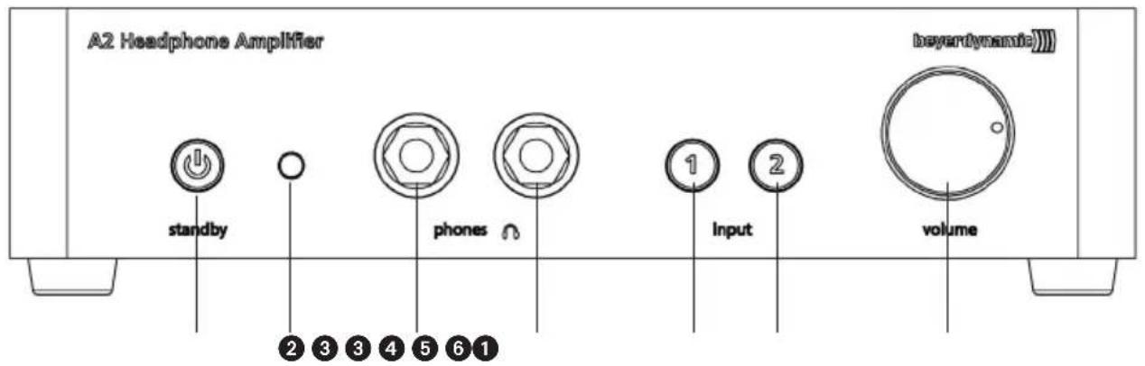
A2 Headphone Amplifier standby phones 1 input volume beyertynamic① Backlit standby button.
Red = Device is in standby mode.
Green = Device is turned on.
② Infrared diode to receive the signals, which are transmitted via the remote control.
③ Headphone sockets, connected in parallel, 1/4" stereo jack (6.35 mm).
In order to connect standard headphones.
Important:
As the headphone sockets are connected in parallel, the volume is controlled for both headphones.
Therefore, we recommend using only headphones of the same impedance to achieve the same volume for both headphones.
4 Backlit button to select input 1 and transmitting the signal of the device connected to input 1. Orange = Input 1 is active.
5 Backlit button to select input 2 and transmitting the signal of the device connected to input 2. Orange = Input 2 is active.
⑥ Volume control to adjust the volume.
Warning/hearing protection:
We would like to point out that listening at high volumes over a long period of time may damage your hearing irreversibly. Therefore, reduce the volume before putting into operation and when changing the audio source, as the connected devices or reproduced audio data can have very different output levels.
Make sure that the set volume is not too high. Rule of thumb: The higher the volume, the shorter the time of listening. According to employer's regulations for safety and health the noise exposure e.g. when working should not exceed 85 dB (low volume). This is an allowed time of listening of 8 hours at maximum. If the volume is increased by 3 dB, the allowed time of listening is halved, i.e. with 88 dB the time of listening is 4 hours, with 91 dB 2 hours and so on.
Rear View
text_image
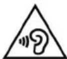
L R input 1 output 1 L R input 2 voltage selector 50/60 Hz max. 15W Made in Germany FC CE ⑦ ⑧ ⑨ ⑩ ⑪⑦ Input 1, stereo RCA phono sockets for signal sources with high levels.
Input sockets = for the connection of audio sources (CD player, DVD player etc.)
8 Looped-through output 1 (hard-wired) = for the connection of devices with high level inputs (stereo amplifiers, active loudspeakers etc.)
At the output 1 you can pick up the audio signal from input 1 ⑦ and route it to your stereo amplifier, active loudspeakers or other devices with standard inputs for high levels. As the signal of the input 1 ⑦ is permanently available at output 1, you can listen to the looped-through audio signal via your hi-fi system, even when the A 2 is turned off.
9 Input 2 = for the connection of another audio source (CD player, DVD player etc.) or amplifier
⑩ Voltage selector switch
Position of the switch 230 V: to select the voltage range of 220 - 240 V
Position of the switch 115 V: to select the voltage range of 110 - 120 V
Warning: Before connecting the A 2 to the mains, please check if the selected voltage range corresponds to the local mains voltage. If you connect the device to a different mains voltage or if you change the position of the voltage selector switch during operation, a short-circuit can occur inside the device and cause damage to the device.
⑪ Mains connection
The A 2 is supplied with a power cable. If the connector of the power cable is not suitable for the local power outlet, please purchase an appropriate power cable at your local dealer.
Bottom
text_image
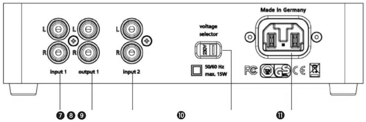
100 Ω output 0 Ω impedance +6 dB gain 0 dB -4 dB CAUTION NEW OF ELECTRIC SHOCK DO NOT OPEN ⑫ ⑬12 Output impedance switch
Select the output impedance according to the impedance of the headphone you are using.
Recommended settings:
0 Ω = When connecting headphones with a low impedance such as 16 Ω or 32 Ω.
100 Ω = When connecting headphones with a middle or high impedance such as 80 Ω, 250 Ω or 600 Ω.
Note:
In both settings the headphone output on the A 2 is protected against short-circuit.
The amplification factors of the A 2 are calibrated in a way that in both settings the same volume is achieved when connecting a headphone with an impedance of 32 Ω.
13 Gain switch
To adapt the gain to the connected player and the headphone.
0 dB = Base setting (factory default setting).
-4 dB = When connecting headphones with a high efficiency or a high-performance player.
+6 dB = When connecting headphones with a low efficiency or a quiet player.
6. Remote Control
Front View
text_image
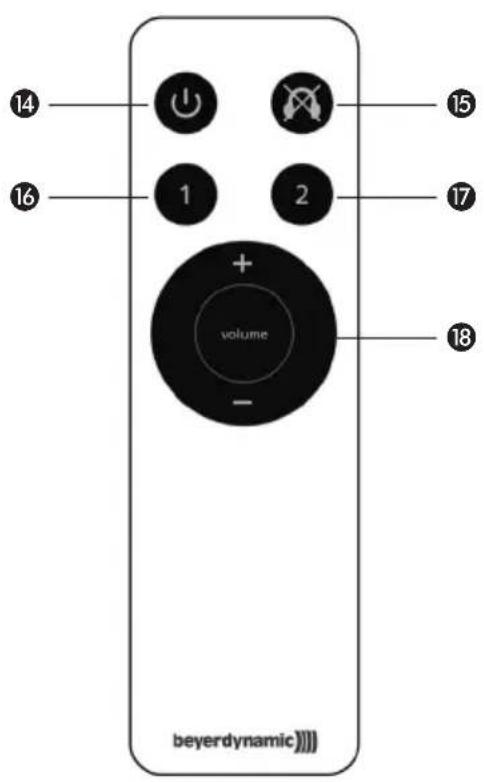
14 15 16 1 2 17 + volume - 18 beyerdynamicRear View
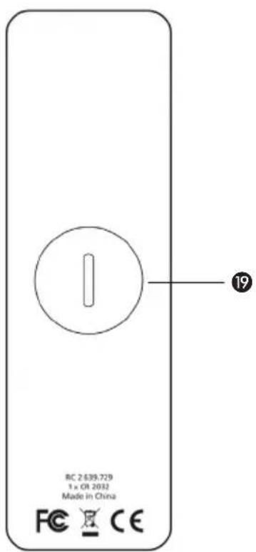
text_image
RC 2.639.729 1 x OR 2032 Made in China FC CE 19The A 2 headphone amplifier can also be controlled via the supplied remote control. The buttons allow the function described below.
Note:
Direct the remote control at the infrared diode 2 of the amplifier. To achieve a wide range, please make sure that the amplifier is not exposed to direct sunlight.
14 On-off button
To turn on or off the A 2 which is connected to the mains.
Standby button ① red: Device is in standby mode.
Standby button ① green: Device is turned on.
15 Mute button
To mute the headphone.
Depending on the active input, the backlit button of the A 2 for input 1 ④ or input 2 ⑤ will go out.
Mute can be deactivated by pressing the mute button once again or by changing the volume with the volume control 18 of the remote control.
16 Selector button "Input 1"
Button to select the input 1 and to transmit the signal of the device connected to input 1 on the A 2.
Orange backlit button "Input 1" ④: Input 1 is active.
⑰ Selector button "Input 2"
Button to select the input 2 and to transmit the signal of the device connected to input 2 on the A 2.
Orange backlit button "Input 2" ⑤: Input 2 is active.
18 Volume control
Press “+” to increase the volume.
The volume control ⑥ on the A 2 will turn to the right and the button for input 1 or input 2 on the A 2 will flash orange as long as the volume control of the remote control is pressed.
Press “-” to reduce the volume.
The volume control ⑥ on the A 2 will turn to the left and the button for input 1 or input 2 on the A 2 will flash orange as long as the volume control of the remote control is pressed.
19 Battery compartment
In order to insert/replace the battery (round cell Li-Mn, CR 2032), please open the battery compartment. Use a coin to turn the cover of the battery compartment 90° anticlockwise. In order to avoid scratches, wrap a soft cloth around the coin.
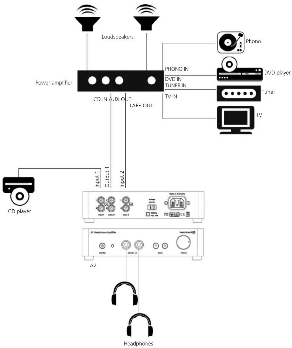
7. Example of Application
flowchart
graph TD
    A["Power amplifier"] --> B["Loudspeakers"]
    A --> C["CD in AUX OUT TAPE OUT"]
    C --> D["Phono"]
    C --> E["Phono IN"]
    C --> F["DVD IN TUNER IN"]
    C --> G["Tuner"]
    C --> H["TV"]
    I["CD player"] --> J["Input 1"]
    I --> K["Output 1"]
    I --> L["Input 2"]
    M["A2 Headphone Amplifier"] --> N["Headphones"]
    O["Main Audio System"] --> P["Main Audio System"]
    Q["Main Audio System"] --> R["Main Audio System"]
Operating Instruction for the Example of Application
- Connect a CD player to the input 1 ⑦ on the A 2.
- Connect the output 1 8 on the A 2 to the CD input of the power amplifier.
- Connect the "AUX Out" or "Tape Out" output of the power amplifier to the input 2 ⑨ on the A 2.
- Connect one or two headphones to the headphone connection ③. Depending on the efficiency and the impedance of the headphone, select the gain ⑬ and the output impedance ⑫ at the bottom of the A 2.
- Connect the A 2 via the mains connection 11 to the mains.
Warning: Before connecting the A 2 to the mains, please check if the voltage range selected with the voltage selector switch 10 corresponds to the local mains voltage. If you connect the device to a different mains voltage or if you change the position of the voltage selector switch 10 during operation, a short-circuit can occur inside the device and cause damage to the device.
- When the A 2 is connected to the mains, the standby button ① will illuminate red.
- Turn on the A 2 by pressing the standby button ① on the A 2 or the button ⑭ of the remote control. The standby button ① will illuminate green and the button ④ or ⑤ will illuminate orange, depending on which input was active when the A 2 was turned off.
- Now you can select one of the two audio sources with the buttons ④ or ⑤ on the A 2 or with the buttons ⑯ or ⑰ of the remote control, i.e. with the button for input 1 ④ or ⑯ you select the CD player or with the button for input 2 ⑤ or ⑰ you select another device connected to the amplifier such as a TV, DVD player, tuner or phono player.
- The signal of input 1 ⑦ is also permanently available at output 1 ⑧. This means you can listen to the looped-through audio signal via your hi-fi system, even when the A 2 is turned off.
- Select the desired volume with the volume control ⑥ or via the remote control ⑱.
- If the headphone is to be muted temporarily, press the mute button 15 of the remote control. The orange illuminating button 4 or 5 of the selected input 1 or 2 will go out. Deactive mute by pressing the mute button 15 once again or by pressing the volume control 18 of the remote control.
- In order to turn off the A 2 press the standby button ① on the A 2 or the button ⑭ of the remote control.
- An intelligent, microprocessor-controlled relay ensures silent switching between the two different audio sources and avoids unpleasant noise or damage to your hearing should a power failure occur or when turning the A 2 on or off.
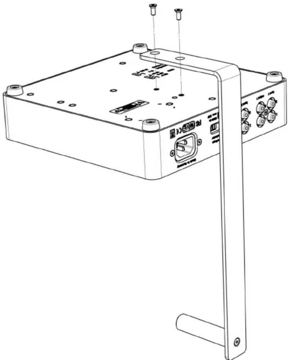
8. How to Mount the Headphone Stand
The A 2 headphone amplifier is supplied with a headphone stand for storing the headphone. You can mount this stand to the A 2.
- Put the device upside down on a soft pad to the very front on the edge of a table.
- Make sure that the holes of the headphone stand match the holes of the A 2 headphone amplifier. Refer to the drawing below.
- Attach the headphone stand with the supplied Allen screws. Tighten the Allen screws by turning the Allen key clockwise.
natural_image
Line drawing of a device rear panel with ports and connectors (no text or symbols)9. Technical Specifications
A 2 Headphone Amplifier
Frequency response. 1 Hz - 100 kHz (-1 dB)
Signal-to-noise ratio ....>101 dB (unweighted)
T.H.D. 0.001% at 170 mW/250 Ω
Input impedance....50 kΩ
Output impedance ....Headphone output 0 Ω/100 Ω (switchable)
Output power 100 mW / 600 Ω
170 mW / 250 Ω
150 mW / 32 Ω
Channel separation L/R ....>89 dB
Maximum gain 18 dB
Power supply . . . . . . . . . . . . . . . . . . . . . . . 110 - 120 V / 220 - 240 V (switchable), 50/60 Hz
Power consumption (operation) ....<15 W
Power consumption (standby)....<0.45 W
Audio connections....2 x line input, gold-plated RCA phono sockets
1 x line output, gold-plated RCA phono sockets
2 x headphone output, 1/4" stereo jack (6.35 mm), gold-plated contacts
Dimensions (W x D x H) 216 x 235 x 55 mm
Height incl. headphone stand ..... 320 mm
Weight 2230 g
Accessories . . . . . . . . . . . . . . . . . . . . . . . . . . . . . IR remote control, headphone stand, power cable
RC 2 Remote Control
Dimensions (W x D x H) 36 x 120 x 9 mm
Weight 36 g
Battery 1 x CR 2032
EC-DECLARATION
OF CONFORMITY
Application of
Council directive:
2004/108/EC
Electromagnetic Compatibility
2006/95/EC
Low Voltage Directive
Standards to which
Conformity is Declared:
EN 55013:2001+A1:2003+A2:2006
EN 55020:2007+A11:2011
EN 60065/A12:2011
Emission
Immunity
Safety
Manufacturer's Name:
beyerdynamic GmbH & Co. KG
Manufacturer's Address:
Theresienstrasse 8, 74072 Heilbronn, Germany
Type of Equipment:
Headphone Amplifier
Model Numbers:
A2
I, the undersigned, as an employee of beyerdynamic, hereby declare that the equipment specified conforms to the above Directive and Standards.
Manufacturer's Signature:
Veriel Rote
Full Name:
Ulrich Roth
Date:
- April 2014
Position:
Director of R&D
beyerdynamic))))

DECLARATION OF CONFORMITY
This device complies with Part 15 of the FCC Rules. Operation is subject to the following two conditions: (1) This device may not cause harmful interference, and (2) This device must accept any interference received, including interference that may cause undesired operation.
Manufacturer:
beyerdynamic GmbH & Co. KG
Theresienstrasse 8
D- 74072 Heilbronn, Germany
U.S. Responsible Party:
beyerdynamic, Inc.
56 Central Avenue
Farmingdale, NY 11735, USA
Contact Person:
Wolfgang Luckhardt, Managing Director
Phone: Tel. (631) 293 3200
Fax: (631) 293 3288
Model/Type:
Headphone Amplifier
A2
Classification:
Class B Digital Device
We hereby declare that the equipment bearing the trade name and model number specified above was tested conforming to the applicable FCC rules under the most accurate measurement standards possible, and that the necessary steps have been taken and are in force to assure that production units of the same equipment will continue to comply with the Commission's requirements.
Manufacturer's Signature:
David Rote
April 1, 2014
U. Roth, Director of R&D
Responsible Party's Signature:
W. Buickand
April 1, 2014
W. Luckhardt, General Manager