VS8100 - Server Vivotek - Free user manual and instructions
Find the device manual for free VS8100 Vivotek in PDF.

| Product Type | Network Video Server |
| Brand | Vivotek |
| Model | VS8100 |
| Video Input Channels | 8 channels |
| Video Compression | H.264, MJPEG |
| Resolution | Up to 1280x1024 per channel |
| Recording Modes | Continuous, schedule, motion detection |
| Network Interface | 10/100/1000 Mbps Ethernet |
| Dimensions (WxHxD) | 230 x 44 x 320 mm |
| Weight | 0.9 kg |
| Power Supply | 12V DC, 1.5A |
| Operating Temperature | 0°C to 45°C |
| Storage Temperature | -20°C to 60°C |
| Humidity | 10% to 90% non-condensing |
| Remote Access | Via web browser and mobile app |
| Storage | Supports up to 2 SATA hard drives (not included) |
| Audio | Audio input and output (RCA) |
| Alarm I/O | 4 alarm inputs, 2 relay outputs |
| Maintenance | Clean with soft dry cloth; avoid liquids |
| Safety | Use only supplied power adapter; keep ventilation clear |
| Warranty | 2 years |
Frequently Asked Questions - VS8100 Vivotek
User questions about VS8100 Vivotek
0 question about this device. Answer the ones you know or ask your own.
Ask a new question about this device
Download the instructions for your Server in PDF format for free! Find your manual VS8100 - Vivotek and take your electronic device back in hand. On this page are published all the documents necessary for the use of your device. VS8100 by Vivotek.
USER MANUAL VS8100 Vivotek
natural_image
Line drawing of a VIVO TEK optical device with ports and lens (no text or symbols on body)Table of Contents
Revision History ....3
Package Contents....3
Overview 4
Read Before Use....4
Physical Description 5
Network Deployment....9
Software Installation....12
Ready to Use....13
Accessing the Video Server 14
Using Web Browsers....14
Using RTSP Players....16
Using 3GPP-compatible Mobile Devices....17
Using VIVOTEK Recording Software....18
Main Page 19
Client settings.... 22
Configuration 25
System 26
System > Homepage layout ....27
System > Logs ....30
System > Parameters .... 32
System > Maintenance....33
Media > Image 37
Media > Video 40
Media > Audio....44
Network > General settings....45
Network > Streaming protocols 52
Network > SNMP (Simple Network Management Protocol).61
Security > User accounts ....62
Security > HTTPS (Hypertext Transfer Protocol over SSL) 63
Security > Access List ....70
PTZ > PTZ settings 75
Event > Event settings....81
Applications > Motion detection....94
Applications > Tampering detection .....97
Recording > Recording settings 98
Appendix 103
URL Commands for the Network Camera/Video Server....103
Technical Specifications .... 185
Technology License Notice....186
Electromagnetic Compatibility (EMC)....187
Revision History
- Rev. 1.0: Initial release.
Package Contents
■ VS8100
■ Quick Installation Guide
Overview
VIVOTEK VS8100 is a small-sized H.264 1-CH video server that helps you migrate from analog to digital surveillance system with ease. Its power sharing with CCTV and tiny design make it ideal for front-end installation and surveillance applications such as home, offices, retail stores, banks, and city surveillance, where their power supply and IP network connections are already settled. VS8100 supports a variety types of analog cameras, including PTZ cameras with its Pan/Tilt/Zoom control through the built-in RS-485 port.
With the high-performance H.264 compression format, it drastically reduces the file sizes and conserves valuable bandwidth and storage space. Supporting simultaneous multiple streams, the video streams can be transmitted in either H.264 or MJPEG formats for versatile applications. The streams can also be individually configured with separate frame rates, resolution, and image quality so as to meet different platforms or bandwidth constraints.
Together with the ST7501 multi-lingual 32-channel recording software, users can set up an easy-to-use IP surveillance system with ease. VIVOTEK also provides the smart phone application iViewer, both for iPhone and Android phones, enable users to monitor live video off-site.
Read Before Use
The use of surveillance devices may be prohibited by law in your country. The video server is not only a high-performance web-ready camera but can also be part of a flexible surveillance system. It is the user's responsibility to ensure that the operation of such devices is legal before installing this unit for its intended use.
It is important to first verify that all contents received are complete according to the Package Contents listed below. Take note of the warnings in the Quick Installation Guide before the video server is installed; then carefully read and follow the instructions in the Installation chapter to avoid damage due to faulty assembly and installation. This also ensures the product is used properly as intended.
The video server is a network device and its use should be straightforward for those who have basic networking knowledge. It is designed for various applications including video sharing, general security/ surveillance, etc. The Configuration chapter suggests ways to best utilize the video server and ensure proper operations. For creative and professional developers, the URL Commands of the video server section serves as a helpful reference to customizing existing homepages or integrating with the current web server.
Physical Description
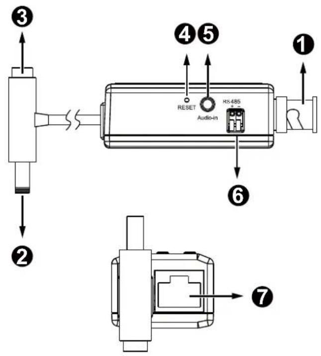
| 1 BNC input (male) |
| 2 DC 12V output (to camera) |
| 3 DC 12V input (to power source) |
| 4 Reset button |
| 5 Audio input phonejack |
| 6 RS485 |
| 7 RJ-45 Ethernet connector |

NOTE:
The video server consumes approximately 12V @ 0.15A = 1.8W power.
Installation
Please refer to the following illustration for the connection method.
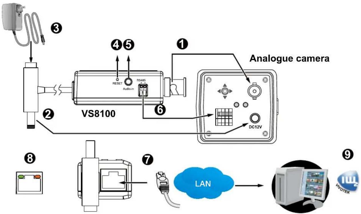
- Connect the BNC input connector to that on an analogue camera.
- Connect the DC 12V output to the 12V input on the analogue camera.
- Connect the DC 12V input to a 12V power source. Normally a 12V 1.5A power adapter will be sufficient.
- The Reset button can be used to re-start the video server.
- If the camera has an embedded microphone, connect a stereo jack to the Audio input.
- If a camera is mounted on a PTZ scanner, you may connect the RS485 pins for PTZ control.
- Connect an Ethernet cable to the RJ45 Ethernet port, and connect another end to an Ethernet switch.
- See the table below for LED definitions.
- Visit www.vivotek.com to download the IW2 utility program. Use the IW2 utility to locate and access your video server.
Status LED
| Item | LED status Description | |
| 1 | Steady Orange Powered on, and system booting | |
| Orange LED off Power is off. | ||
| 2 | Steady Orange & Green blinking every 1 sec.(Green LED on for 1 sec., and off for another 1 sec.) | Network is working (heartbeat) |
| Steady Orange & Green LED off Network failed. | ||
| 3 | Orange blinks every 0.15 sec. + Green blinks every 1 sec. (Orange on for 0.15 sec. and off for 0.15 sec.) (Green on for 1 sec and off for 1 sec.) | Upgrading firmware |
| 4 | Orange blinks every 0.15 sec. + Green blinks every 0.15 sec. (LEDs on together on for 0.15 sec and off for 0.15 sec., and repeat the pattern) | Restoring defaults |
Hardware Reset
The reset button is used to reset the system or restore the factory default settings. Sometimes resetting the system can return the video server to normal operation. If the system problems remain after reset, restore the factory settings and install again.
Reset: Press and release the recessed reset button using a straightened paper clip. Wait for the video server to reboot.
Network Deployment
Setting up the Video Server over the Internet
There are several ways to set up the video server over the Internet. The first way is to set up the video server behind a router. The second way is to utilize a static IP. The third way is to use PPPoE.
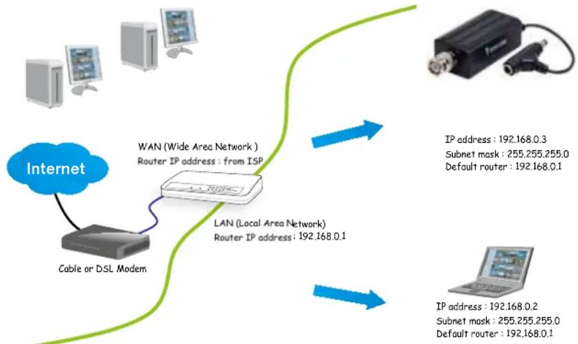
Internet connection via a router
Before setting up the video server over the Internet, make sure you have a router and follow the steps below.
- Connect your video server behind a router, the Internet environment is illustrated below. Regarding how to obtain your IP address, please refer to Software Installation on page 12 for details.
flowchart
graph TD
    A["Internet"] --> B["Cable or DSL Modem"]
    B --> C["WAN (Wide Area Network) Router IP address: from ISP"]
    C --> D["LAN (Local Area Network) Router IP address: 192.168.0.1"]
    D --> E["IP address: 192.168.0.3\nSubnet mask: 255.255.255.0\nDefault router: 192.168.0.1"]
    D --> F["IP address: 192.168.0.2\nSubnet mask: 255.255.255.0\nDefault router: 192.168.0.1"]
- In this case, if the Local Area Network (LAN) IP address of your Video server is 192.168.0.3, please forward the following ports for the Video server on the router.
■ Secondary HTTP port: 8080
■ RTSP port: 554
■ RTP port for audio: 5558
■ RTCP port for audio: 5559
■ RTP port for video: 5556
■ RTCP port for video: 5557
If you have changed the port numbers on the Network page, please open the ports accordingly on your router. For information on how to forward ports on the router, please refer to your router's user's manual.
- Find out the public IP address of your router provided by your ISP (Internet Service Provider). Use the public IP and the secondary HTTP port to access the Video server from the Internet. Please refer to Network Type on page 89 for details.
For example, your router and IP settings may look like this:
| Device IP Address: internal port | IP Address: External Port (Mapped port on the router) |
| Public IP of router 122.146.57.120 | |
| LAN IP of router 192.168.2.1 | |
| Camera 1 192.168.2.10:80 122.146.57.120:8000 | |
| Camera 2 192.168.2.11:80 122.146.57.120:8001 | |
| ... ... ... | |
Configure the router, virtual server or firewall, so that the router can forward any data coming into a preconfigured port number to a network camera on the private network, and allow data from the camera to be transmitted to the outside of the network over the same path.
| From Forward to | |
| 122.146.57.120:8000 19 | 2.168.2.10:80 |
| 122.146.57.120:8001 19 | 2.168.2.11:80 |
| ... ... |
When properly configured, you can access a camera behind the router using the HTTP request as follows: http://122.146.57.120:8000
If you change the port numbers on the Network configuration page, please open the ports accordingly on your router. For example, you can open a management session with your router to configure access through the router to the camera within your local network. Please consult your network administrator for router configuration if you have troubles with the configuration.
For more information with network configuration options (such as that of streaming ports), please refer to Configuration > Network Settings. VIVOTEK also provides the automatic port forwarding feature as an NAT traversal function with the precondition that your router must support the UPnP port forwarding feature.
Internet connection with static IP
Choose this connection type if you are required to use a static IP for the Video server. Please refer to LAN on page 45 for details.
Internet connection via PPPoE (Point-to-Point over Ethernet)
Choose this connection type if you are connected to the Internet via a DSL Line. Please refer to PPPoE on page 41 for details.
Software Installation
Download Installation Wizard 2 (IW2) from VIVOTEK's website. The utility helps you set up your video server on the LAN.
- Install IW2. When done, double click the IW2 shortcut on your desktop to launch the program.
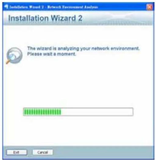
- The program will conduct an analysis of your network environment. After your network environment is analyzed, please click Next to continue the program.
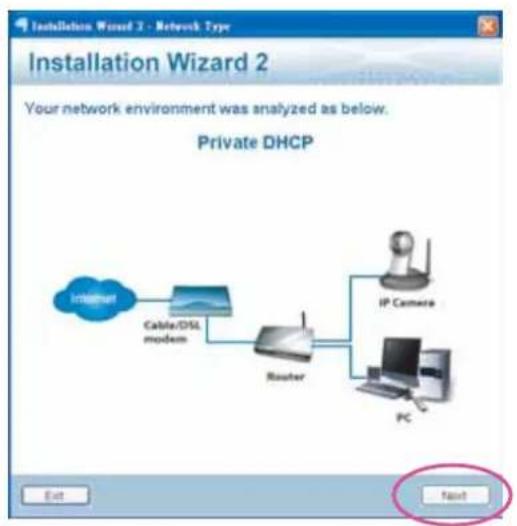
flowchart
graph LR
    A["Internet"] --> B["Cable/DISL modem"]
    B --> C["Router"]
    C --> D["IP Camera"]
    D --> E["PC"]
    E --> F["Next"]
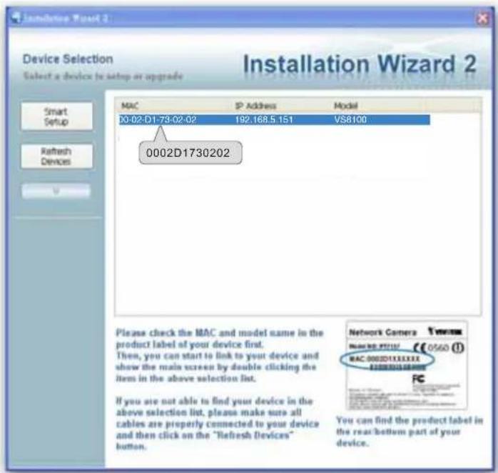
- The program will search for all VIVOTEK network devices on the same LAN.
- After a brief search, the main installer window will prompt. Double-click on the MAC and model name which matches the product label on your device to connect to the Network Camera via a web browser.

Ready to Use
- A browser session with the Video Server should prompt as shown below.
- You should be able to see live video from your camera. You may also install the 32-channel recording software from VIVOTEK's website in a deployment consisting of multiple cameras. For its installation details, please refer to its related documents.
Accessing the Video Server
This chapter explains how to access the video server through web browsers, RTSP players, 3GPP-compatible mobile devices, and VIVOTEK recording software.
Using Web Browsers
Use Installation Wizard 2 (IW2) to access to the video servers on the LAN.
If your network environment is not a LAN, follow these steps to access the Network Camera:
- Launch your web browser (e.g., Microsoft® Internet Explorer or Mozilla Firefox).
- Enter the IP address of the video server in the address field. Press Enter.
- The live video will be displayed in your web browser.
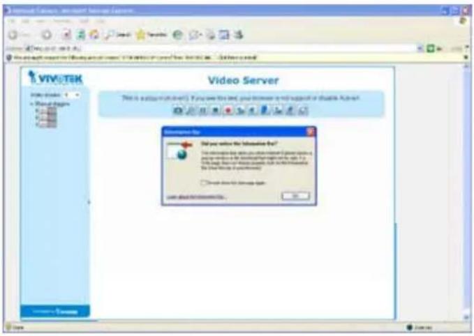
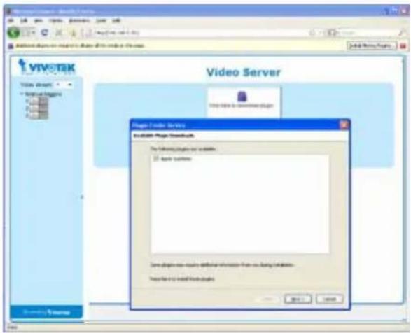
- If it is the first time installing the VIVOTEK video server, an information bar will pop up as shown below. Follow the instructions to install the required plug-ins on your computer.

NOTE:
By default, the video server is not password-protected. To prevent unauthorized access, it is highly recommended to set a password for the video server. For more information about how to enable password protection, please refer to Security on page 82.
If you see a dialog box indicating that your security settings prohibit running ActiveX ^ Controls, please enable the ActiveX ^ Controls for your browser.
1. Choose Tools > Internet Options > Security > Custom Level.
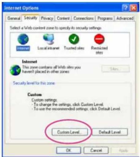
- Look for Download signed ActiveX ^® controls; select Enable or Prompt. Click OK.
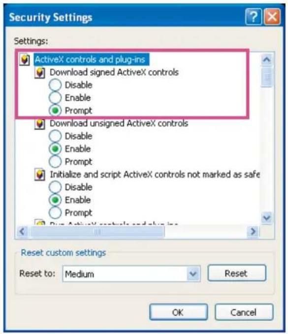
- Refresh your web browser, then install the Active X^® control. Follow the instructions to complete installation.
Using RTSP Players
To view the live view streaming media using RTSP players, you can use one of the following players that support RTSP streaming.

Quick Time Player
VLC Player
- Launch the RTSP player.
- Choose File > Open URL. A URL dialog box will pop up.
- The address format is rtsp://
: /
As most ISPs and players only allow RTSP streaming through port number 554, please set the RTSP port to 554. For more information, please refer to RTSP Streaming on page 53.
For example:
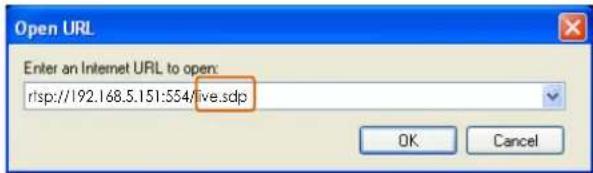
- The live video will be displayed in your player.
For more information on how to configure the RTSP access name, please refer to RTSP Streaming on page 53 for details.
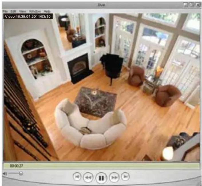
natural_image
Interior view of a modern living room with white furniture and large windows (no visible text or symbols)Using 3GPP-compatible Mobile Devices
To view the streaming media through 3GPP-compatible mobile devices, make sure the video server can be accessed over the Internet. For more information on how to set up the video server over the Internet, please refer to Setup the video server over the Internet on page 9.
To utilize this feature, please check the following settings on your video server:
-
Because most players on 3GPP mobile phones do not support RTSP authentication, make sure the authentication mode of RTSP streaming is set to disable.
For more information, please refer to RTSP Streaming on page 53. -
As the bandwidth on 3G networks is limited, you will not be able to use a large video size. Please configure the video and audio streaming parameters as listed below.
| Video Mode H.264 | |
| Frame size QCIF | |
| Maximum frame rate 5 fps | |
| Intra frame period 1S | |
| Video quality (Constant bit rate) 40kbps | |
| Audio type (G.711) 64kbps | |
-
As most ISPs and players only allow RTSP streaming through port number 554, please set the RTSP port to 554. For more information, please refer to RTSP Streaming on page 53.
-
Launch the player on the 3GPP-compatible mobile devices (e.g., VLC Player).
-
Type the following URL commands into the player.
The address format is rtsp://
For example:
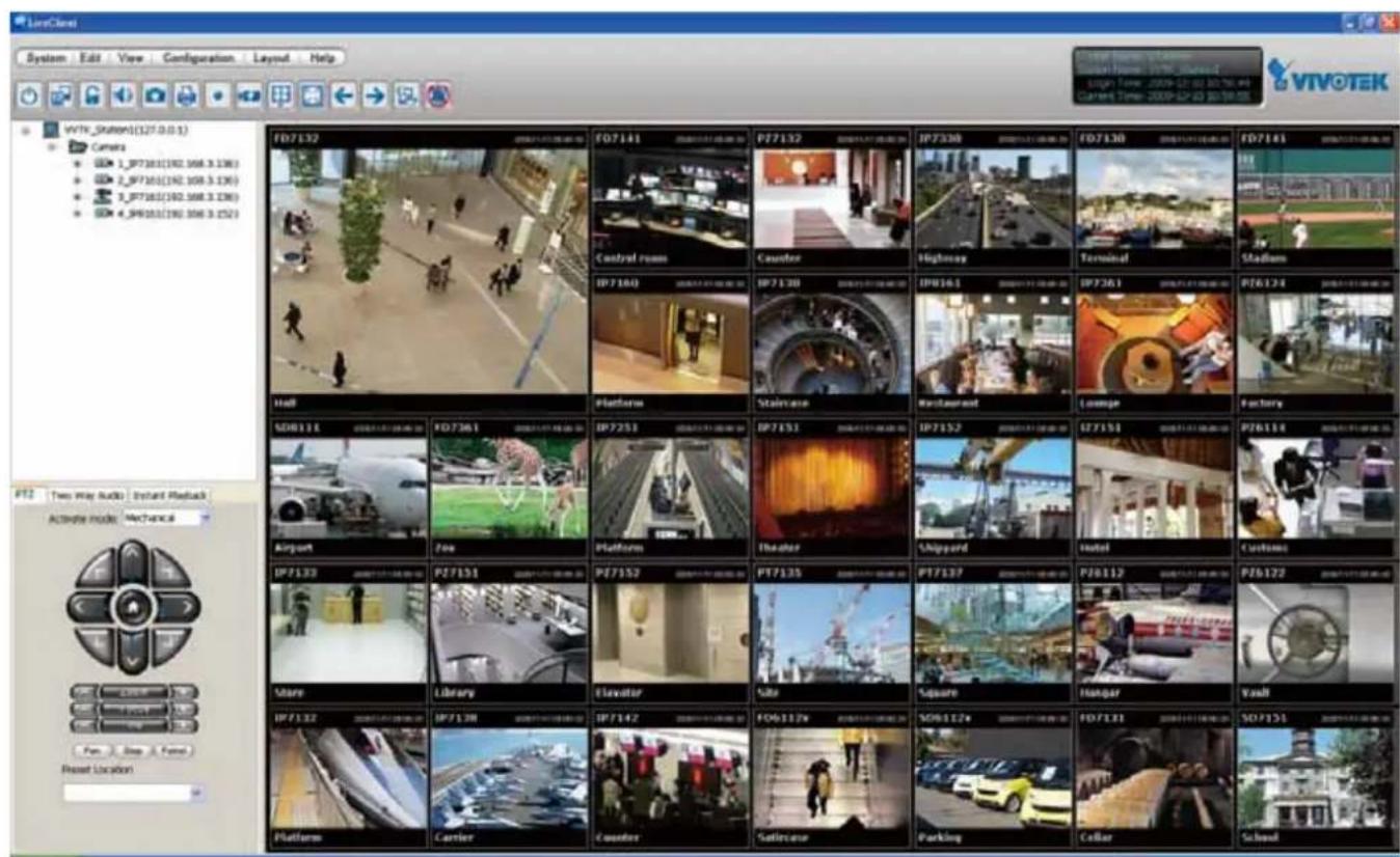
Using VIVOTEK Recording Software
The recording software, allowing simultaneous monitoring and video recording for multiple video servers. Please install the recording software; then launch the program to add the video server to the Channel list. For detailed information about how to use the recording software, please refer to the user's manual of the software or download it from http://www.vivotek.com.
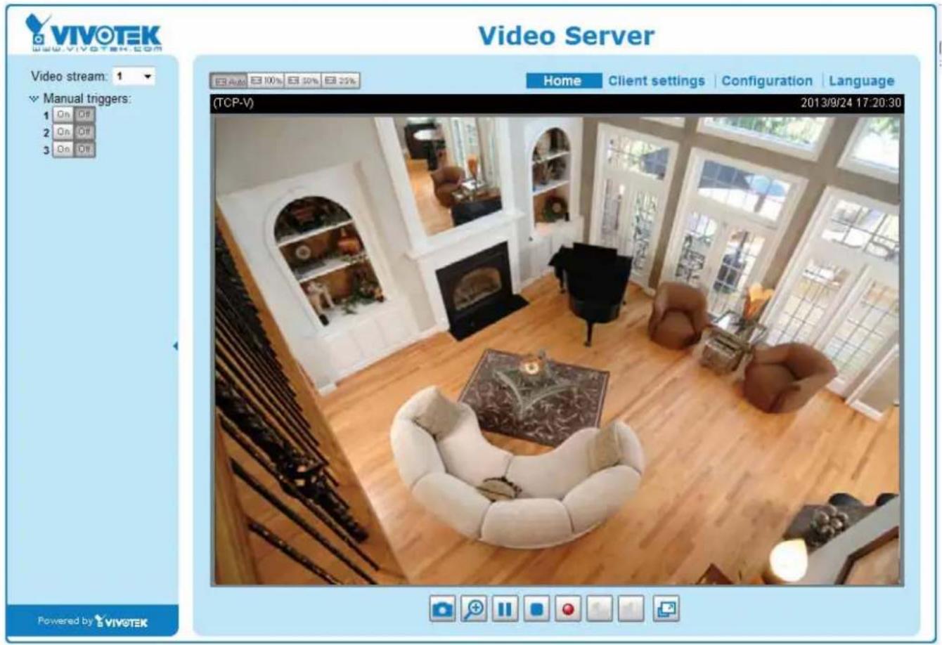
Main Page
This chapter explains the layout of the main page. It is composed of the following sections: VIVOTEK INC. Logo, Host Name, Camera Control Area, Configuration Area, Menu, and Live Video Window. The Manual Trigger and Digital Input/Digital Output control menus are expandable and collapsible, while the PTZ navigation panel is available only when a PTZ camera is attached.
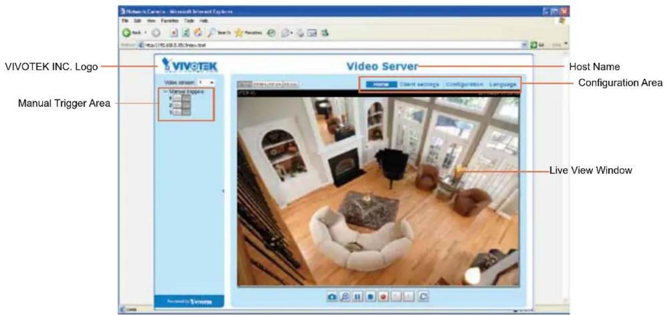
VIVOTEK INC. Logo
Click this logo to visit the VIVOTEK website.
Host Name
The host name can be customized to fit your needs. For more information, please refer to System settings on page 26.
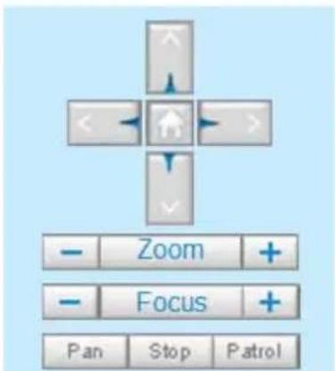
Camera Control Area
Video Stream: VS8100 supports 1 channel for video live viewing. The channel allows you to view only one stream. For more information about video settings, please refer to page 40 for detailed information.
PTZ Control Area: The up/down/left/right/zoom/focus/pan buttons allow you to adjust the video in the viewing window to the spot you wish to watch. Home button allows you to resume the center of the screen. Click Patrol to move from one point to another; click it again to stop patrolling. Click Stop to stop the pan movement. Please refer to Configuration > PTZ on page 75 for more information.
Pan/Tilt/Zoom Speed: In the drop-down list, the speed ranges from -5\~5 (slow/fast).
Note that PTZ panel is only available when the Mechanical PTZ function is enabled.
Manual Trigger Area
Click to enable/disable an event trigger manually. Please configure an event setting on Application page before enable this function. A total of 4 event settings can be configured. For more information about event settings, please refer to page 81.
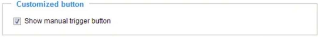
If you want to hide this item on the homepage, please go to the Homepage layout page to uncheck "show manual trigger button". Please refer to page 27 for details.
Configuration Area
Client Settings: Click this button to access the client setting page. For more information, please refer to Client Settings on page 22.
Configuration: Click this button to access the configuration page of the video server. It is suggested that a password be applied to the video server so that only the administrator can configure the video server. For more information, please refer to Configuration on page 25.
Language: Click this button to choose a language for the user interface. Language options are available in: English, Deutsch, Español, Français, Italiano, 日本語, Português, 簡体中文, and 繁體中文.
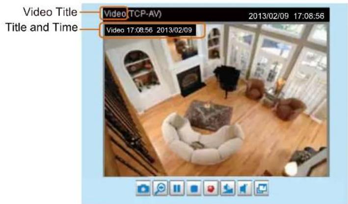
Live Video Window
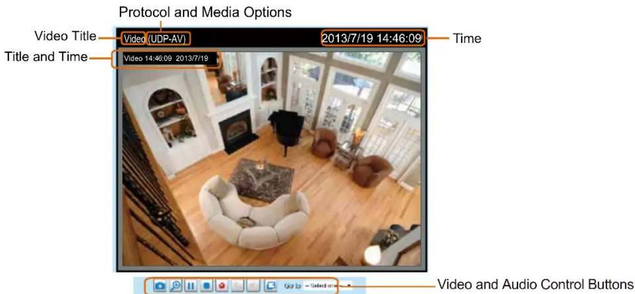
Video Title: The video title can be configured. For more information, please refer to Video settings on page 40.
Protocol and Media Options: The transmission protocol and media options for video streaming. For further configuration, please refer to Client settings on page 22.
Time: Display the current time. For further configuration, please refer to Video settings on page 40.
Title and Time: The video title and time can be stamped on the streaming video. For further configuration, please refer to Video settings on page 40. Video and Audio Control Buttons: Depending on the video server model and video server configuration, some buttons may not be available.
Snapshot: Click this button to capture and save still images. The captured images will be displayed in a pop-up window. Right-click the image and choose Save Picture As to save it in JPEG (*.jpg) or BMP (*.bmp) format.
Digital Zoom: Click and uncheck "Disable digital zoom" to enable the zoom operation. The navigation screen indicates the part of the image being magnified. To control the zoom level, drag the slider bar. To move to a different area you want to magnify, drag the navigation screen.

Pause: Pause the transmission of the streaming media. The button becomes the Resume button after clicking the Pause button.
Stop: Stop the transmission of the streaming media. Click the Resume button to continue transmission.
Start MP4 Recording: Click this button to record video clips in MP4 file format to your computer. Press the □ Stop MP4 Recording button to end recording. When you exit the web browser, video recording stops accordingly. To specify the storage destination and file name, please refer to MP4 saving options on page 23 for details.
Volume: When the Mute function is not activated, move the slider bar to adjust the volume on the local computer.
Mute: Turn off the volume on the local computer. The button becomes the Audio On button after clicking the Mute button.
Full Screen: Click this button to switch to full screen mode. Press the "Esc" key to switch back to normal mode.
Go to: The drop-down menu enables you to locate and move to a preset location instantly on the viewing window.
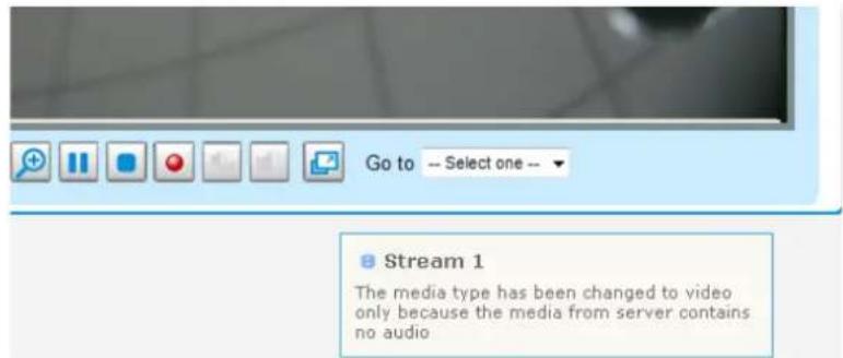
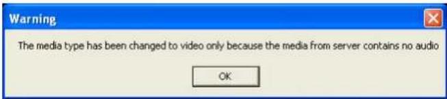
If you mute the audio option onboard (in Media > Audio window), or you select an MJPEG video stream that contains no audio input, you will be prompted by the following message on an IE browser.
Client settings
This chapter explains how to select the stream transmission mode and saving options on the local computer. When completed with the settings on this page, click Save on the page bottom to enable the settings.
H.264 media options
H.264 media options
Video and audio
Video only
Audio only
Select to stream video or audio data or both. This is enabled only when the video mode is set to H.264.
H.264 protocol options
H.264 protocol options
○ UDP unicast
© UDP multicast
TCP
HTTP
Depending on your network environment, there are four transmission modes of H.264:
UDP unicast: This protocol allows for more real-time audio and video streams. However, network packets may be lost due to network burst traffic and images may be broken. Activate UDP connection when occasions require time-sensitive responses and the video quality is less important. Note that each unicast client connecting to the server takes up additional bandwidth and the video server allows up to ten simultaneous accesses.
UDP multicast: This protocol allows multicast-enabled routers to forward network packets to all clients requesting streaming media. This helps to reduce the network transmission load of the video server while serving multiple clients at the same time. Note that to utilize this feature, the video server must be configured to enable multicast streaming at the same time. For more information, please refer to RTSP Streaming on page 53.
TCP: This protocol guarantees the complete delivery of streaming data and thus provides better video quality. The downside of this protocol is that its real-time effect is not as good as that of the UDP protocol.
HTTP: This protocol allows the same quality as TCP protocol without needing to open specific ports for streaming under some network environments. Users inside a firewall can utilize this protocol to allow streaming data through.
MP4 saving options
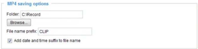
Users can record live video as they are watching it by clicking Start MP4 Recording on the main page. Here, you can specify the storage destination and file name.
Folder: Specify a storage destination for the recorded video files.
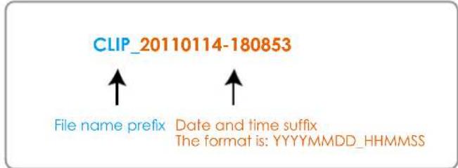
File name prefix: Enter the text that will be appended to the front of the video file name.
Add date and time suffix to the file name: Select this option to append the date and time to the end of the file name.
Local Streaming Buffer Time
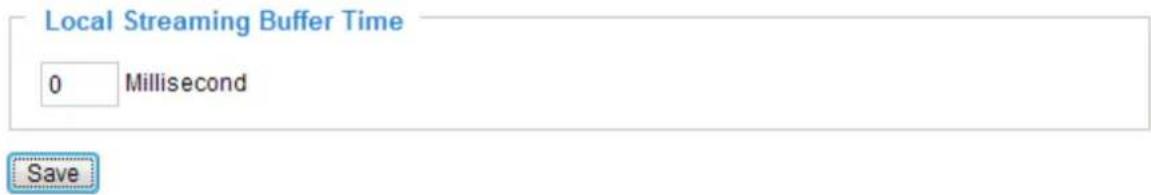
Due to the unsteady bandwidth flow, the live streaming may lag and not be very smoothly. If you enable this option, the live streaming will be stored temporarily on your client PC's cache memory for a few seconds/milli-seconds before being played on the live viewing window. This will help you see the streaming more smoothly. If you enter 3,000 Millisecond, the streaming will delay for 3 seconds.
Joystick settings
Joystick settings
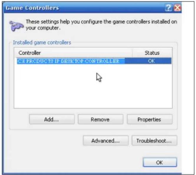
Selected joystick: CH PRODUCTS IP DESKTOP CONTROLLER
Calibrate
Configure buttons
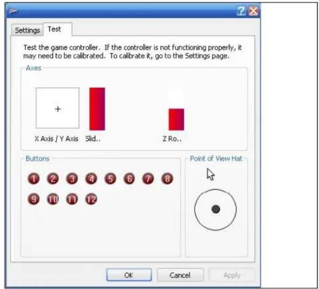
Calibrate: Make sure a joystick is already attached to your COM port or USB port on your client computer. Click on the Calibrate button and the Windows Game Controller function will be started. If properly connected, your operating system should have already detected the joystick. Follow the onscreen instructions to calibrate your joystick.
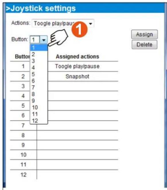
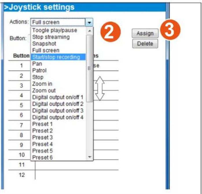
Configure buttons: You can define individual joystick buttons using this function. Click to open a configuration window and assign functions to joystick buttons using the following steps: 1. Select a button using the pull-down menu. 2. Select an Action to be toggled by the button. 3. Click on the Assign button, and then repeat the process to define other buttons.
Configuration
Click Configuration on the main page to enter the camera setting pages. Note that only Administrators can access the configuration page.
VIVOTEK offers an easy-to-use user interface that helps you set up your video server with minimal effort.
In order to simplify the user interface, the detailed information will be hidden unless you click on the function item. When you click on the first sub-item, the detailed information for the first sub-item will be displayed; when you click on the second sub-item, the detailed information for the second sub-item will be displayed and that of the first sub-item will be hidden.
The following is the main configuration page:
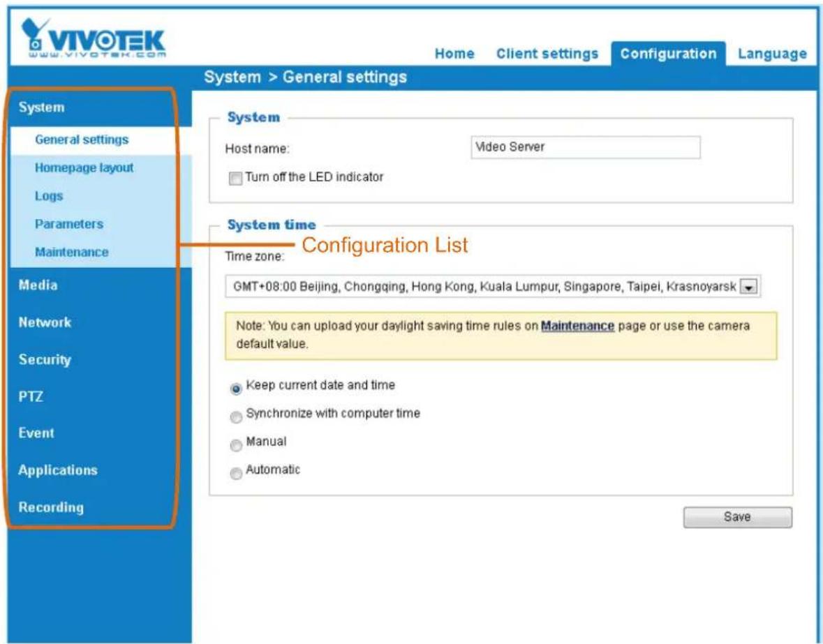
System
This section explains how to configure the basic settings for the video server, such as the host name and system time. It is composed of the following three columns: System, System Time and DI and DO. When finished with the settings on this page, click Save at the bottom of the page to enable the settings.
System

Host name: Enter a desired name for the video server. The text will be displayed at the top of the main page.
Turn off the LED indicators: If you do not want to let others know that the video server is in operation, you can select this option to turn off the LED indicators.
System time
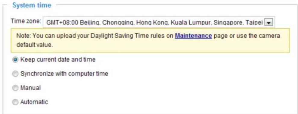
Time zone : Select the appropriate time zone from the list. If you want to upload Daylight Savings Time rules on the Maintenance page, please refer to Upload / Export daylight saving time configuration file on page 34 for details.
Keep current date and time: Select this option to preserve the current date and time of the Video server. The video server's internal real-time clock maintains the date and time even when the power of the system is turned off.
Sync with computer time: Select this option to synchronize the date and time of the video server with the local computer. The read-only date and time of the PC is displayed as updated.
Manual: The administrator can enter the date and time manually. Note that the date and time format are [yyyy/mm/dd] and [hh:mm:ss].
Automatic: The Network Time Protocol is a protocol which synchronizes computer clocks by periodically querying an NTP Server.
NTP server: Assign the IP address or domain name of the time-server. Leaving the text box blank connects the video server to the default time servers.
Update interval: Select to update the time using the NTP server on an hourly, daily, weekly, or monthly basis.
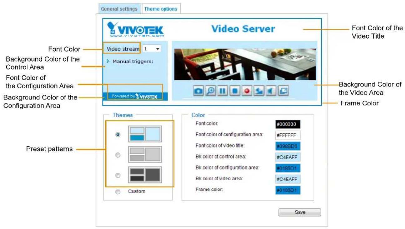
This section explains how to set up your own customized homepage layout.
General settings
This column shows the settings of your homage layout. You can manually select the background and font colors in Theme Options (the second tab on this page). The settings will be displayed automatically in this Preview field. The following shows the homepage using the default settings:
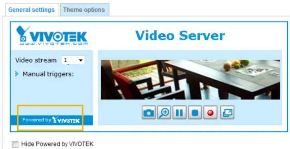
■ Hide Powered by VIVOTEK: If you check this item, it will be removed from the homepage.
Logo graph
Here you can change the logo that is placed at the top of your homepage.
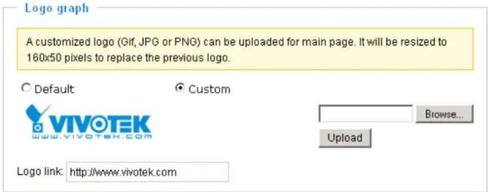
Follow the steps below to upload a new logo:
- Click Custom and the Browse field will appear.
- Select a logo from your files.
- Click Upload to replace the existing logo with a new one.
- Enter a website link if necessary.
- Click Save to enable the settings.
Customized button
If you want to hide manual trigger buttons on the homepage, please uncheck this item. This item is checked by default. Customized button
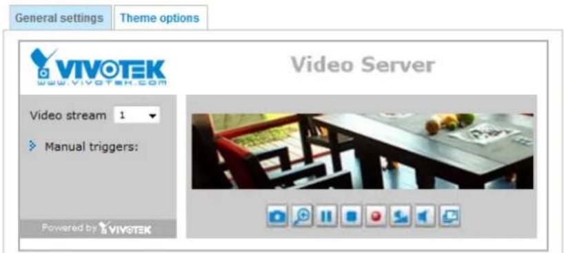
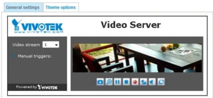
Theme Options
Here you can change the color of your homepage layout. There are three types of preset patterns for you to choose from. The new layout will simultaneously appear in the Preview filed. Click Save to enable the settings.
■ Follow the steps below to set up the customed homepage:
- Click Custom on the left column.
- Click the field where you want to change the color on the right column.
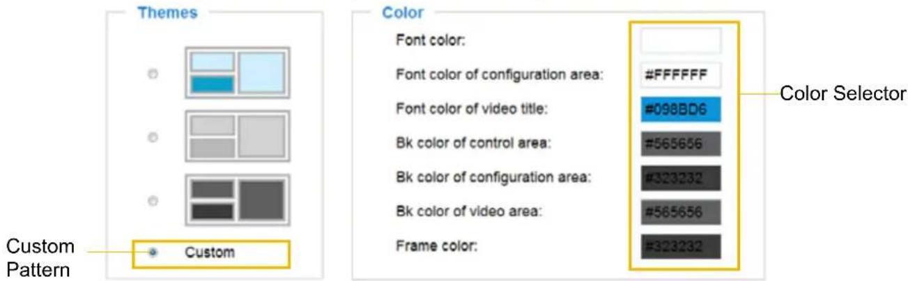
- The palette window will pop up as shown below.
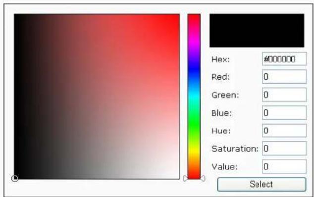
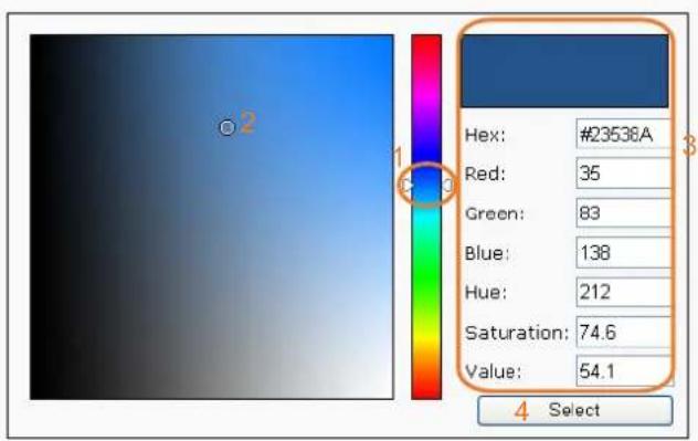
- Drag the slider bar and click on the left square to select a desired color.
- The selected color will be displayed in the corresponding fields and in the Preview column.
- Click Save to enable the settings.
System > Logs
This section explains how to configure the Network Camera to send the system log to a remote server as backup.
Log server settings
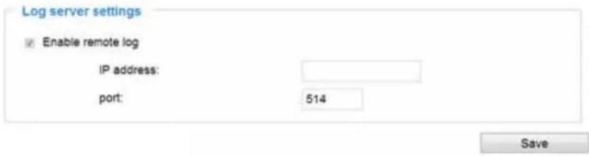
Follow the steps below to set up the remote log:
- Select Enable remote log.
- In the IP address text box, enter the IP address of the remote server.
- In the port text box, enter the port number of the remote server.
- When completed, click Save to enable the setting.
You can configure the Network Camera to send the system log file to a remote server as a log backup. Before utilizing this feature, it is suggested that the user install a log-recording tool to receive system log messages from the Network Camera. An example is Kiwi Syslog Daemon. Visit http://www.kiwisyslog.com/kiwi-syslog-daemon-overview/.
![Kew Syslog Harmon (Version 7.1.4) File View Help Display 00 (Default) Date Time Priority Hostname Message 01-12-2000 15:21:32 User.info 192.168.5.121 [RITSP SERVER]: Stop one session, IP=192.168.5.122 01-12-2000 15:21:31 User.info 192.168.5.121 [RITSP SERVER]: Start one session, IP=192.168.5.122 01-12-2000 15:20:47 Syslog.info 192.168.5.121 syslogd 1.4.1: restart. 100% 3 MPH 15:34 01-12-2000](/content/2026/05/1031529/images/002c27e638155c09bb9f5e3a3c274950fc6bcf021fe4dee2c4c8f4d4f840adf6.jpg)
System log
![Jan 5 11:36:07 syslogd 1.5.0 restart. Jan 5 11:36:08 [swatchdog]: Ready to watch httpd. Jan 5 11:36:09 [EVENT MGR]: Starting eventmgr with support for EcTun Jan 5 11:36:11 [DRM Service]: Starting DRM service. Jan 5 11:36:20 [UPnPIGDCP]: Search IGD failed Jan 5 11:36:23 automount[718]: >> mount: mounting /dev/mmcblk0p1 on /mnt/auto/CF failed: No such device or address Jan 5 11:36:23 automount[718]: mount generic): failed to mount /dev/mmcblk0p1 (type vfat) on /mnt/auto/CF Jan 5 11:36:23 [IR Cut Control]: Day mode Jan 5 11:36:23 automount[728]: >> mount: mounting /dev/mmcblk0p1 on /mnt/auto/CF failed: No such device or address Jan 5 11:36:23 automount[728]: mount generic): failed to mount /dev/mmcblk0p1 (type vfat) on /mnt/auto/CF Jan 5 11:36:23 [IR Cut Control]: Day mode Jan 5 11:36:23 [SYS]: Serial number = 0002D10ED4C9 Jan 5 11:36:23 [SYS]: System starts at Wed Jan 5 11:36:23 UTC 2011](/content/2026/05/1031529/images/551821bba0bb6e8a4db518c1e7b6240e92cff3e152104cb72aec42ffeb5af0c6.jpg)
This column displays the system log in a chronological order. The system log is stored in the Network Camera's buffer area and will be overwritten when reaching a certain limit.
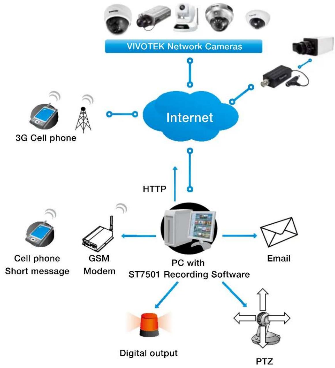
You can install the included ST7501 recording software, which provides an Event Management function group for delivering event messages via emails, GSM short messages, onscreen event panel, or to trigger an alarm, etc. For more information, refer to the ST7501 User Manual.
flowchart
graph TD
    A["VIVOTEK Network Cameras"] --> B["Internet"]
    B --> C["3G Cell phone"]
    B --> D["GSM Modem"]
    B --> E["Cell phone Short message"]
    B --> F["Digital output"]
    B --> G["PTZ"]
    B --> H["PC with ST7501 Recording Software"]
    H --> I["Email"]
    B --> J["HTTP"]
    J --> H
    style B fill:#99ccff,stroke:#333
Access log
System log Access log
Jan 5 11:36:28 [RTSP SERVER]: Start one session, IP=172.16.2.52
Jan 5 11:49:15 [RTSP SERVER]: Start one session, IP=192.168.4.105
Jan 5 13:11:20 [RTSP SERVER]: Start one session, IP=192.168.4.105
Access log displays the access time and IP address of all viewers (including operators and administrators) in a chronological order. The access log is stored in the Network Camera's buffer area and will be overwritten when reaching a certain limit.
System > Parameters
The View Parameters page lists the entire system's parameters. If you need technical assistance, please provide the information listed on this page.
Parameters
system_hostname='Video Server'
system_ledoff='0'
system_lowlight='1'
system_date='1970/01/01'
system_time='02:37:44'
system_datetime�'
system_ntp='
system_timezone timezoneindex='320'
system_daylight_enable='0'
system_daylight_dstactualmode='1'
system_daylight_auto_begintime='NONE'
system_daylight_auto_endtime='NONE'
system_daylight_timezones=',-360,-320,-280,-240,-241,-200,-201,-
system_updateinterval='0'
system_info_modelname='VS8100'
system_info_extendedmodelname='VS8100'
system_info_serialnumber='0002D1810007'
system_info_firmwareversion='VS8100-VVTK-0100b'
system_info_language_count='9'
system_info_language_i0='English'
system_info_language_i1='Deutsch'
system_info_language_i2='Español'
system_info_language_i3='Français'
System > Maintenance
This chapter explains how to restore the Network Camera to factory default, upgrade firmware version, etc.
General settings > Upgrade firmware
Upgrade firmware
Firmware file:
Browse...
Upgrade
This feature allows you to upgrade the firmware of your Network Camera. It takes a few minutes to complete the process.
Note: Do not power off the Network Camera during the upgrade!
Follow the steps below to upgrade the firmware:
- Download the latest firmware file from the VIVOTEK website. The file is in .pkg file format.
- Click Browse... and locate the firmware file.
- Click Upgrade. The Network Camera starts to upgrade and will reboot automatically when the upgrade completes.
If the upgrade is successful, you will see "Reboot system now!! This connection will close". After that, re-access the Network Camera.
The following message is displayed when the upgrade has succeeded.
Reboot system now!! This connection will close.
The following message is displayed when you have selected an incorrect firmware file.
Starting firmware upgrade...
Do not power down the server during the upgrade.
The server will restart automatically after the upgrade is completed.
This will take about 1 - 5 minutes.
Wrong PKG file format
Unpack fail
General settings > Reboot
Reboot
Reboot
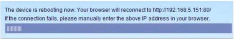
This feature allows you to reboot the Network Camera, which takes about one minute to complete. When completed, the live video page will be displayed in your browser. The following message will be displayed during the reboot process.
The device is rebooting now. Your browser will reconnect to http://192.168.5.151:80/ If the connection fails, please manually enter the above IP address in your browser.
[Non-Text]
If the connection fails after rebooting, manually enter the IP address of the Network Camera in the address field to resume the connection.
General settings > Restore
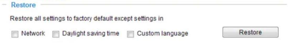
This feature allows you to restore the Network Camera to factory default settings.
Network: Select this option to retain the Network Type settings (please refer to Network Type on page 45).
Daylight Saving Time: Select this option to retain the Daylight Saving Time settings (please refer to Import/Export files below on this page).
Custom Language: Select this option to retain the Custom Language settings.
If none of the options is selected, all settings will be restored to factory default. The following message is displayed during the restoring process.
Import/Export files
This feature allows you to Export / Update daylight saving time rules, custom language file, configuration file, and server status report.
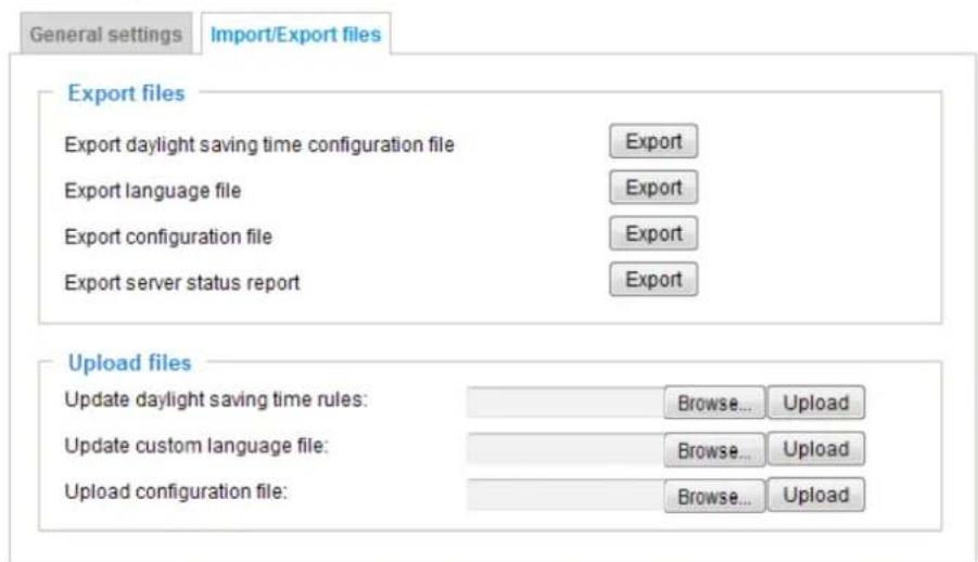
Export daylight saving time configuration file: Click to set the start and end time of DST (Daylight Saving).
Follow the steps below to export:
-
In the Export files column, click Export to export the daylight saving time configuration file from the Network Camera.
-
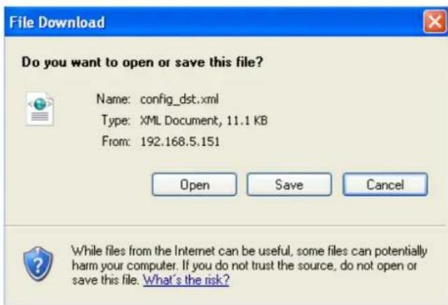
A file download dialog will pop up as shown below. Click Open to review the XML file or click Save to store the file for editing.
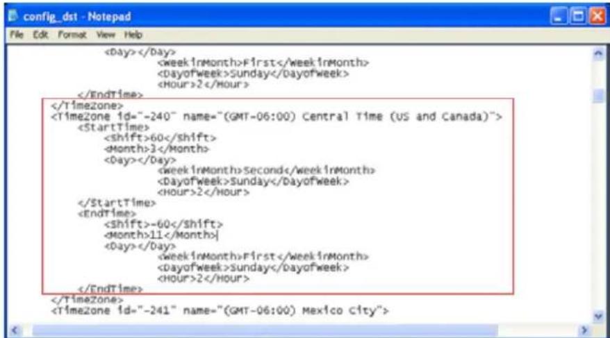
- Open the file with Microsoft ^® Notepad and locate your time zone; set the start and end time of DST. When completed, save the file.
In the example below, DST begins each year at 2:00 a.m. on the second Sunday in March and ends at 2:00 a.m. on the first Sunday in November.
Update daylight saving time rules: Click Browse... and specify the XML file to update.
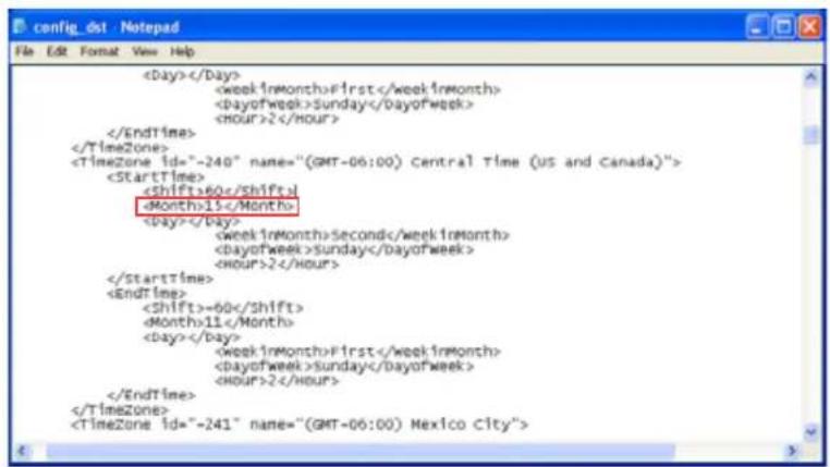
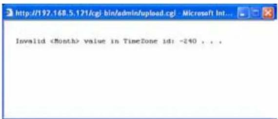
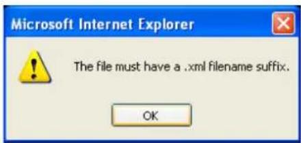
If the incorrect date and time are assigned, you will see the following warning message when uploading the file to the Network Camera.
The following message is displayed when attempting to upload an incorrect file format.
Export language file: Click to export language strings. VIVOTEK provides nine languages: English, Deutsch, Español, Français, Italiano, 日本語, Português, 簡体中文, and 繁體中文.
Update custom language file: Click Browse... and specify your own custom language file to upload.
Export configuration file: Click to export all parameters for the device and user-defined scripts.
Update configuration file: Click Browse... to update a configuration file. Please note that the model and firmware version of the device should be the same as the configuration file. If you have set up a fixed IP or other special settings for your device, it is not suggested to update a configuration file.
Export server staus report: Click to export the current server status report, such as time, logs, parameters, process status, memory status, file system status, network status, kernel message ... and so on.

Tips:
- If a firmware upgrade is accidentally disrupted, say, by a power outage, you still have a last resort method to restore normal operation. See the following for how to bring the camera back to work:
Applicable scenario:
(1) Power disconnected during firmware upgrade.
(2) Unknown reason causing abnormal LED status, and a Restore cannot recover normal working condition.
You can use the following methods to activate the camera with its backup firmware:
(1) Press and hold down the reset button for at least one minute.
(2) Power on the camera until the Red LED blinks rapidly.
(3) After boot up, the firmware should return to the previous version before the camera hanged. (The procedure should take 5 to 10 minutes, longer than the normal boot-up process). When this process is completed, the LED status should return to normal.
Media > Image
This section explains how to configure the image settings of the Network Camera. It is composed of the following four columns: General settings, Image settings, Exposure, and Privacy mask.
General settings
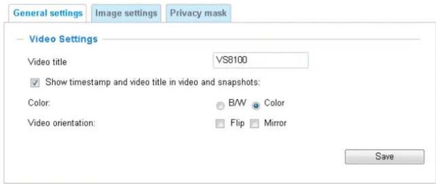
Video title
Show timestamp and video title in video and snapshots: Enter a name that will be displayed on the title bar of the live video as the picture shown below.
Color: Select to display color or black/white video streams.
Video orientation: Flip - vertically reflect the display of the live video; Mirror - horizontally reflect the display of the live video. Select both options if the Network Camera is installed upside-down (e.g., on the ceiling) to correct the image orientation. Please note that if you have preset locations, those locations will be cleared after flip/mirror setting.
Image settings
On this page, you can tune the White balance and Image adjustment.
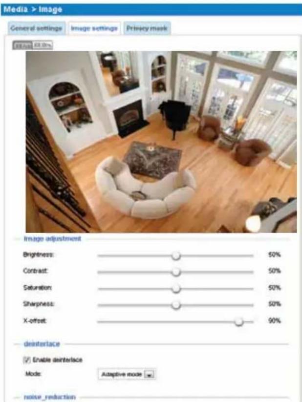
Image Adjustment
■ Brightness: Adjust the image brightness level, which ranges from 0% to 100%.
■ Contrast: Adjust the image contrast level, which ranges from 0% to 100%.
■ Saturation: Adjust the image saturation level, which ranges from 0% to 100%.
■ Sharpness: Adjust the image sharpness level, which ranges from 0% to 100%.
■ X-offset: Adjust the image to the proper position horizontally.
■ Enable deinterlace: Check to enable deinterlace, and choose Adaptive mode or Blend mode in the drop-down list. Adaptive mode provides the best image quality, while Blend mode provides better image quality (than not using the deinterlace function at all).
■ Enable noise reduction: Check to enable noise reduction in order to reduce noises and flickers in image. This applies to the onboard 3D Noise Reduction feature. Use the pull-down menu to adjust the reduction strength. Note that applying this function to the video channel will consume system computing power.
3D Noise Reduction is mostly applied in low-light conditions. When enabled in a low-light condition with fast moving objects, trails of after-images may occur. You may then select a lower strength level or disable the function.
■ Restore: Click to restore the default setting.
■ Save: When finished with the setting, click Save to enable the settings.
Privacy mask
Click Privacy Mask to open the settings page. On this page, you can block out sensitive zones to address privacy concerns.
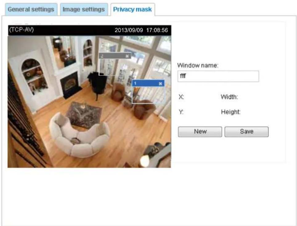
■ To set the privacy mask windows, follow the steps below:
- Click New to add a new window.
- You can use the mouse cursor to size and drag-drop the window, which is recommended to be at least twice the size of the object (height and width) you want to cover.
- Enter a Window Name and click Save to enable the setting.
- Click on the Enable privacy mask checkbox to enable this function.

NOTE:
▶ Up to 5 privacy mask windows can be set up on the same screen.
▶ If you want to delete the privacy mask window, please click the 'x' on the upper right corner of the window.
Media > Video
Stream settings
Stream
Video settings for stream 1
Video settings for stream 2
Video settings for stream 3
Save
This Network Camera supports multiple streams with frame sizes ranging QCIF (176x144) to D1 (704x480 NTSC pixels).
Click the stream item to display the detailed information. The maximum frame size will follow your settings in the above Viewing Window sections.
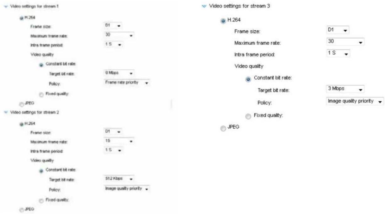
This Network Camera provides real-time H.264 and MJPEG compression standards (Dual Codec) for real-time viewing. If the H.264 mode is selected, the video is streamed via RTSP protocol. There are several parameters through which you can adjust the video performance:
■ Frame size
You can set up different video resolutions for different viewing devices. For example, set a smaller frame size and lower bit rate for remote viewing on mobile phones and a larger video size and a higher bit rate for live viewing on web browsers. Note that a larger frame size takes up more bandwidth.
■ Maximum frame rate
This limits the maximum refresh frame rate per second. Set the frame rate higher for smoother video quality and for recognizing moving objects in the field of view.
If the power line frequency is set to 50Hz, the frame rates are selectable at 1fps, 2fps, 3fps, 5fps, 8fps, 10fps, 12fps, 15fps, 20fps, and 25fps. If the power line frequency is set to 60Hz, the frame rates are selectable at 1fps, 2fps, 3fps, 5fps, 8fps, 10fps, 12fps, 15fps, 20fps, 25fps, and 30fps. You can also select Customize and manually enter a value.
The frame rate will decrease if you select a higher resolution.
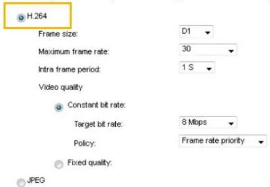
■ Intra frame period
Determine how often for firmware to plant an I frame. The shorter the duration, the more likely you will get better video quality, but at the cost of higher network bandwidth consumption. Select the intra frame period from the following durations: 1/4 second, 1/2 second, 1 second, 2 seconds, 3 seconds, and 4 seconds.
■ Video quality
- Constant bit rate: A complex scene generally produces a larger file size, meaning that higher bandwidth will be needed for data transmission. The bandwidth utilization is configurable to match a selected level, resulting in mutable video quality performance. The bit rates are selectable at the following rates: 20Kbps, 30Kbps, 40Kbps, 50Kbps, 64Kbps, 128Kbps, 256Kbps, 512Kbps, 768Kbps, 1Mbps, 2Mbps, 3Mbps, 4Mbps, 6Mbps, and 8Mbps. You can also select Customize and manually enter a value.
- Target bit rate: select a bit rate from the pull-down menu. The bit rate ranges from 20kbps to a maximum of 40Mbps. The bit rate then becomes the Average or Upper bound bit rate number. The Network Camera will strive to deliver video streams around or within the bit rate limitation you impose.
- Policy: If Frame Rate Priority is selected, the Network Camera will try to maintain the frame rate per second performance, while the image quality will be compromised. If Image quality priority is selected, the Network Camera may drop some video frames in order to maintain image quality.
- Fixed quality: On the other hand, if Fixed quality is selected, all frames are transmitted with the same quality; bandwidth utilization is therefore unpredictable. The video quality can be adjusted to the following settings: Medium, Standard, Good, Detailed, and Excellent. You can also select Customize and manually enter a value.
- Maximum bit rate: With the guaranteed image quality, you might still want to place a bit rate limitation to control the size of video streams for bandwidth and storage concerns. The configurable bit rate starts from 1Mbps to 40Mbps. This can ensure bandwidth is not exhausted when extra-high bit rate is accidentally produced, e.g., lots of noises in a video taken by the night time.
You may also manually enter a bit rate number by selecting the Customized option.
If JPEG mode is selected, the Network Camera sends consecutive JPEG images to the client, producing a moving effect similar to a filmstrip. Every single JPEG image transmitted guarantees the same image quality, which in turn comes at the expense of variable bandwidth usage. Because the media contents are a combination of JPEG images, no audio data is transmitted to the client. There are three parameters provided in MJPEG mode to control the video performance:
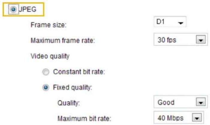
■ Frame size
You can set up different video resolution for different viewing devices. For example, set a smaller frame size and lower bit rate for remote viewing on mobile phones and a larger video size and a higher bit rate for live viewing on web browsers. Note that a larger frame size takes up more bandwidth.
■ Maximum frame rate
This limits the maximum refresh frame rate per second. Set the frame rate higher for smoother video quality.
If the power line frequency is set to 50Hz, the frame rates are selectable at 1fps, 2fps, 3fps, 5fps, 8fps, 10fps, 12fps, 15fps, 20fps, and 25fps. If the power line frequency is set to 60Hz, the frame rates are selectable at 1fps, 2fps, 3fps, 5fps, 8fps, 10fps, 12fps, 15fps, 20fps, 25fps, and 30fps. You can also select Customize and manually enter a value. The frame rate will decrease if you select a higher resolution.
■ Video quality
Refer to the previous page setting an average or upper bound threshold for controlling the bandwidth consumed for transmitting motion jpegs. The configuration method is identical to that for H.264.
For Constant Bit Rate and other settings, refer to the previous page for details.

NOTE:
▶ Video quality and fixed quality refers to the compression rate, so a lower value will produce higher quality.
▶ Converting high-quality video may significantly increase the CPU loading, and you may encounter streaming disconnection or video loss while capturing a complicated scene. In the event of occurrence, we suggest you customize a lower video resolution or reduce the frame rate to obtain smooth video.
Media > Audio
Audio Settings
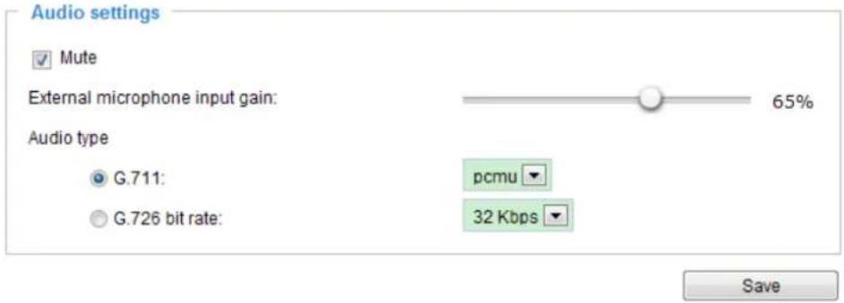
Mute: Select this option to disable audio transmission from the Network Camera to all clients. Note that if muted, no audio data will be transmitted even if audio transmission is enabled on the Client Settings page. In that case, the following message is displayed:
External microphone input gain: Select the gain of the internal audio input according to ambient conditions. Adjust the gain from 100% (most sensitive) to 0% (least sensitive).
Audio type: .
■ G.711 provides good sound quality and requires about 64Kbps. Select the operation mode as pcmu (μ-Law) or pcma (A-Law) mode.
■ G.726 is a speech codec standard covering voice transmission at rates of 16, 24, 32, and 40kbit/s.
When completed with the settings on this page, click Save to enable the settings.
Network > General settings
This section explains how to configure a wired network connection for the Network Camera.
Network Type
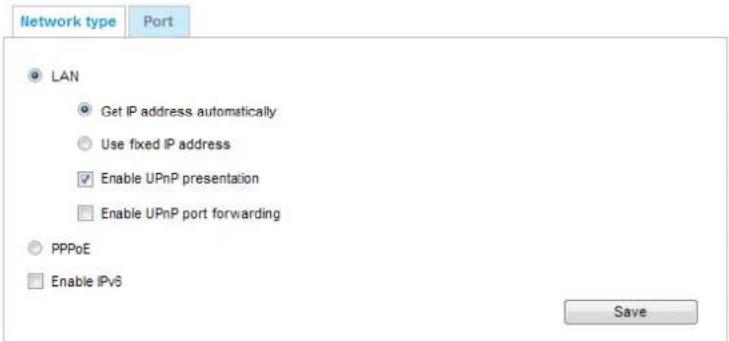
LAN
Select this option when the Network Camera is deployed on a local area network (LAN) and is intended to be accessed by local computers. The default setting for the Network Type is LAN. Please rememer to click on the Save button when you complete the Network setting.
Get IP address automatically: Select this option to obtain an available dynamic IP address assigned by the DHCP server each time the camera is connected to the LAN.
Use fixed IP address: Select this option to manually assign a static IP address to the Network Camera.
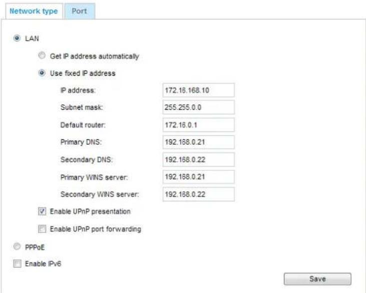
- You can make use of VIVOTEK Installation Wizard 2 on the software CD to easily set up the Network Camera on LAN. Please refer to Software Installation on page 12 for details.
- Enter the Static IP, Subnet mask, Default router, and Primary DNS provided by your ISP or network administrator.
Subnet mask: This is used to determine if the destination is in the same subnet. The default value is "255.255.255.0".
Default router: This is the gateway used to forward frames to destinations in a different subnet. Invalid router setting will disable the transmission to destinations across different subnets.
Primary DNS: The primary domain name server that translates hostnames into IP addresses.
Secondary DNS: Secondary domain name server that backups the Primary DNS.
Primary WINS server: The primary WINS server that maintains the database of computer names and IP addresses.
Secondary WINS server: The secondary WINS server that maintains the database of computer names and IP addresses.
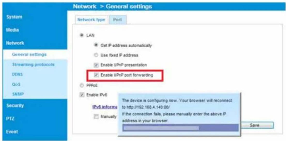
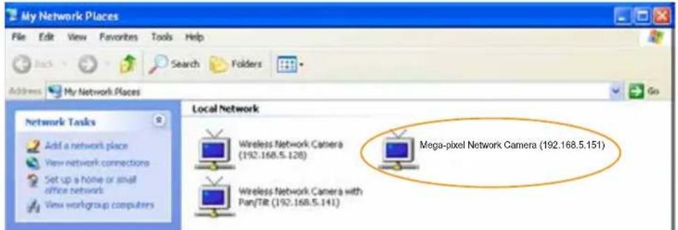
Enable UPnP presentation: Select this option to enable UPnP ^TM presentation for your Network Camera so that whenever a Network Camera is presented to the LAN, the shortcuts to connected Network Cameras will be listed in My Network Places. You can click the shortcut to link to the web browser. Currently, UPnP ^TM is supported by Windows XP or later. Note that to utilize this feature, please make sure the UPnP ^TM component is installed on your computer.
Enable UPnP port forwarding: To access the Network Camera from the Internet, select this option to allow the Network Camera to open ports automatically on the router so that video streams can be sent out from a LAN. To utilize of this feature, make sure that your router supports UPnP ^™ and it is activated.
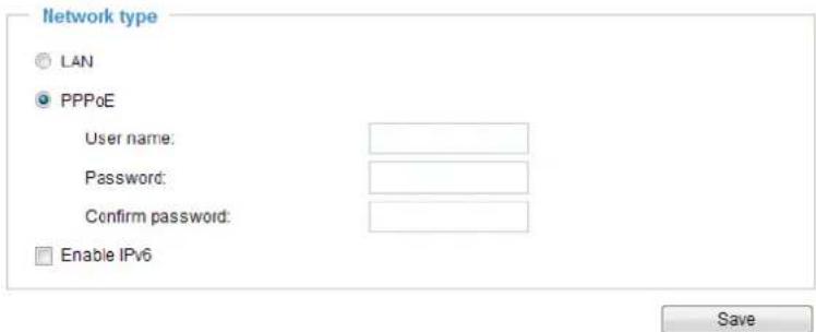
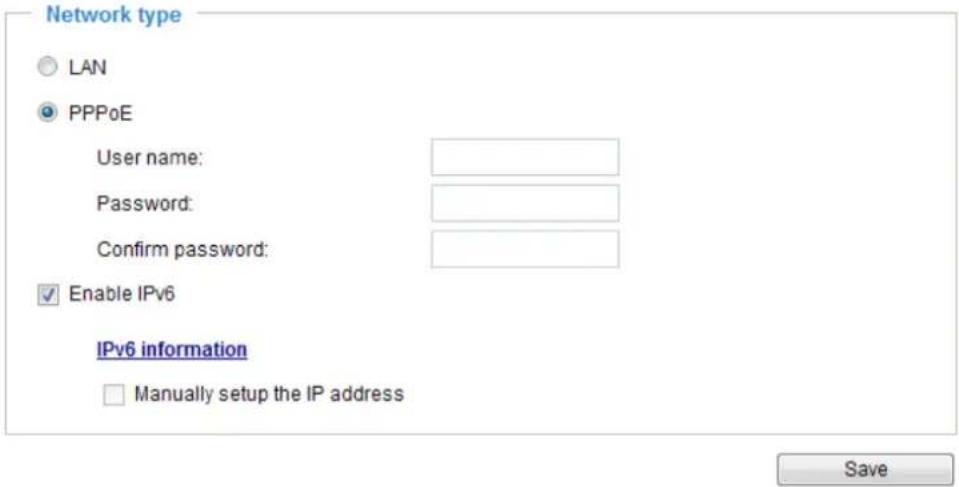
PPPoE (Point-to-point over Ethernet)
Select this option to configure your Network Camera to make it accessible from anywhere as long as there is an Internet connection. Note that to utilize this feature, it requires an account provided by your ISP.
Follow the steps below to acquire your Network Camera's public IP address.
- Set up the Network Camera on the LAN.
- Go to Configuration > Event > Event settings > Add server (please refer to Add server on page 84) to add a new email or FTP server.
- Go to Configuration > Event > Event settings > Add media (please refer to Add media on page 89). Select System log so that you will receive the system log in TXT file format which contains the Network Camera's public IP address in your email or on the FTP server.
- Go to Configuration > Network > General settings > Network type. Select PPPoE and enter the user name and password provided by your ISP. Click Save to enable the setting.
- The Network Camera will reboot.
- Disconnect the power to the Network Camera; remove it from the LAN environment.

NOTE:
▶ If the default ports are already used by other devices connected to the same router, the Network Camera will select other ports for the Network Camera.
If UPnP ^TM is not supported by your router, you will see the following message: Error: Router does not support UPnP port forwarding.
▶ Steps to enable the UPnP ^TM user interface on your computer:
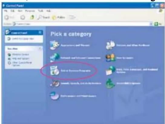
Note that you must log on to the computer as a system administrator to install the UPnP ^TM components.
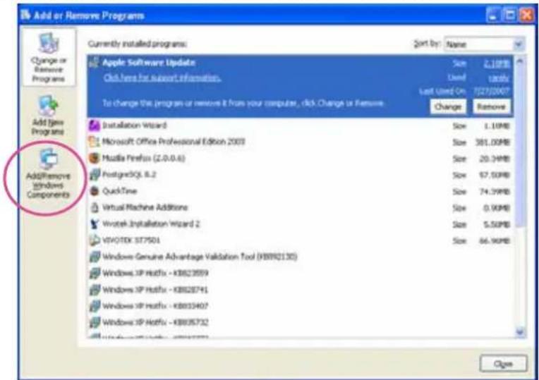
- Go to Start, click Control Panel, then click Add or Remove Programs.
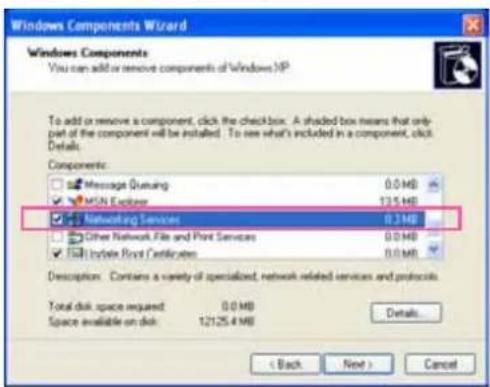
- In the Add or Remove Programs dialog box, click Add/Remove Windows Components.
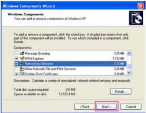
- In the Windows Components Wizard dialog box, select Networking Services and click Details.
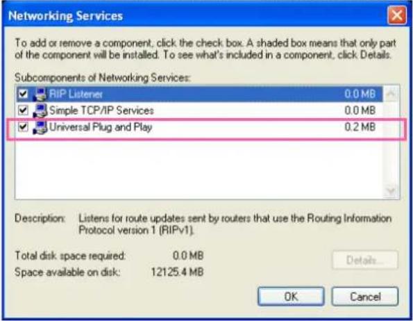
- In the Networking Services dialog box, select Universal Plug and Play and click OK.
- Click Next in the following window.
- Click Finish. UPnP ^TM is enabled.
▶ How does UPnP ^TM work?
UPnP ^TM networking technology provides automatic IP configuration and dynamic discovery of devices added to a network. Services and capabilities offered by networked devices, such as printing and file sharing, are available among each other without the need for cumbersome network configuration. In the case of Network Cameras, you will see Network Camera shortcuts under My Network Places.
▶ Enabling UPnP port forwarding allows the Network Camera to open a secondary HTTP port on the router-not HTTP port-meaning that you have to add the secondary HTTP port number to the Network Camera's public address in order to access the Network Camera from the Internet. For example, when the HTTP port is set to 80 and the secondary HTTP port is set to 8080, refer to the list below for the Network Camera's IP address.
| From the Internet In LAN | |
| http://203.67.124.123:8080 http://192.168.4.160 or http://192.168.4.160:8080 | |
▶ If the PPPoE settings are incorrectly configured or the Internet access is not working, restore the Network Camera to factory default; please refer to Restore on page 33 for details. After the Network Camera is reset to factory default, it will be accessible on the LAN.
Enable IPv6
Select the Enable IPv6 checkbox and click Save to enable IPv6 settings.
Please note that this only works if your network environment and hardware equipment support IPv6. The browser should be Microsoft® Internet Explorer 7 or 8, Mozilla Firefox 13.0 or above.
When IPv6 is enabled, by default, the network camera will listen to router advertisements and be assigned with a link-local IPv6 address accordingly.
IPv6 Information: Click this button to obtain the IPv6 information as shown below.
![[etb0 address] fe80.0000.0000.0000.0202.d1ff:fe0e:d4c8/64@Link [Gateway] IPv6 address list of gateway [DNS] IPv6 address list of DNS](/content/2026/05/1031529/images/52731aa30a5c9e205043780c96112c1a19ccc94363e00a482409182a0f9ad086.jpg)
If your IPv6 settings are successful, the IPv6 address list will be listed in the pop-up window. The IPv6 address will be displayed as follows:
Refers to Ethernet
![[eth0 address] 2001:0c08:2500:0002:0202:d1ff:fe04:65f4/64@Global Link-global IPv6 address/network mask fe80:0000:0000:0000:0202:d1ff:fe04:65f4/64@Link Link-local IPv6 address/network mask [Gateway] fe80:211:d8ff:fea2:1a2b [DNS] 2010:05c0:978d::](/content/2026/05/1031529/images/a65f37c0fbd5d5980dda8713a7f8d8c26d02304e2f16843cb3f439c47e5247c8.jpg)
Please follow the steps below to link to an IPv6 address:
- Open your web browser.
- Enter the link-global or link-local IPv6 address in the address bar of your web browser.
- The format should be:
![http://[2001:0c08:2500:0002:0202:d1ff:fe04:65f4]/ IPv6 address](/content/2026/05/1031529/images/f6734e832ac13586fda2bca0d982a408608050c0e1987b7916ee9c98953b4feb.jpg)
- Press Enter on the keyboard or click Refresh button to refresh the webpage. For example:
![Network Camera - Microsoft Internet Explorer File Edit View Favorites Tools Help Back Search Favorites Address http://[2001:0c08:2500:0002:0202:d1ff:fe04:65f4]/ VIVOTEK www.vivotek.com](/content/2026/05/1031529/images/15627072e4538275c59f2f444a62ceb3ea2d1beb3bec174a61db15668d671940.jpg)

NOTE:
▶ If you have a Secondary HTTP port (the default value is 8080), you can also link to the webpage using the following address format: (Please refer to HTTP streaming on page 52 for detailed information.)
http://[2001:0c08:2500:0002:0202:d1ff:fe04:65f4]/:8080

IPv6 address

Secondary HTTP port
▶ If you choose PPPoE as the Network Type, the [PPP0 address] will be displayed in the IPv6 information column as shown below.
[eth0 address]
fe80:0000:0000:0000:0202:d1ff:fe11:2299/64@Link
[ppp0 address]
fe80:0000:0000:0000:0202:d1ff:fe11:2299/10@Link
2001:b100:01c0:0002:0202:d1ff:fe11:2299/64@Global
[Gateway]
fe80:90:1a00:4142:8ced
[DNS]
2001:6000::1
Manually setup the IP address: Select this option to manually configure IPv6 settings if your network environment does not have DHCPv6 server and router advertisements-enabled routers. If you check this item, the following blanks will be displayed for you to enter the corresponding information:
Enable IPv6
IPv6 information
√ Manually setup the IP address
Optional IP address / Prefix length
Optional default router
Optional primary DNS
Port
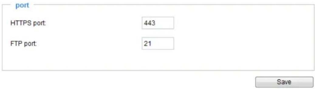
HTTPS port: By default, the HTTPS port is set to 443. It can also be assigned to another port number between 1025 and 65535.
FTP port: The FTP server allows the user to save recorded video clips. You can utilize VIVOTEK's Installation Wizard 2 to upgrade the firmware via FTP server. By default, the FTP port is set to 21. It also can be assigned to another port number between 1025 and 65535.
Network > Streaming protocols
HTTP streaming
To utilize HTTP authentication, make sure that your have set a password for the Network Camera first; please refer to Security > User account on page 62 for details.
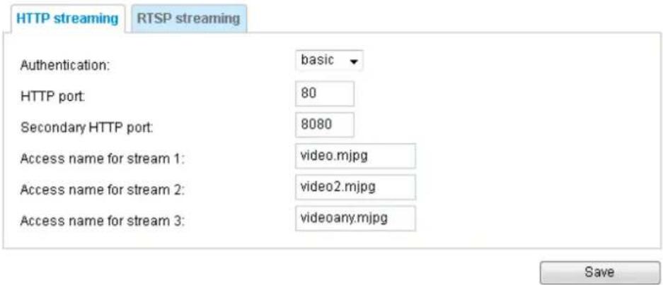
Authentication: Depending on your network security requirements, the Network Camera provides two types of security settings for an HTTP transaction: basic and digest.
If basic authentication is selected, the password is sent in plain text format and there can be potential risks of being intercepted. If digest authentication is selected, user credentials are encrypted using MD5 algorithm and thus provide better protection against unauthorized accesses.
HTTP port / Secondary HTTP port: By default, the HTTP port is set to 80 and the secondary HTTP port is set to 8080. They can also be assigned to another port number between 1025 and 65535. If the ports are incorrectly assigned, the following warning messages will be displayed:
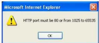
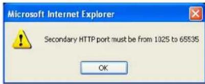
To access the Network Camera on the LAN, both the HTTP port and secondary HTTP port can be used to access the Network Camera. For example, when the HTTP port is set to 80 and the secondary HTTP port is set to 8080, refer to the list below for the Network Camera's IP address.
| On the LAN |
| http://192.168.4.160 or http://192.168.4.160:8080 |
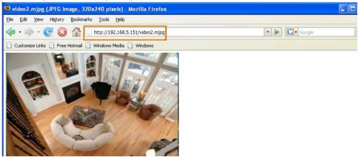
Access name for stream 1 \~ 3: This Network camera supports multiple streams simultaneously. The access name is used to identify different video streams. Users can click Media > Video > Stream settings to set up the video quality of linked streams. For more information about how to set up the video quality, please refer to Stream settings on page 40.
When using Mozilla Firefox to access the Network Camera and the video mode is set to JPEG, users will receive video comprised of continuous JPEG images. This technology, known as “server push”, allows the Network Camera to feed live pictures to Mozilla Firefox.
URL command -- http://
- Launch Mozilla Firefox or Netscape.
- Type the above URL command in the address bar. Press Enter.
- The JPEG images will be displayed in your web browser.

NOTE:
▶ Microsoft® Internet Explorer does not support server push technology; therefore, you will not be able to access a video stream using http://
RTSP Streaming
To utilize RTSP streaming authentication, make sure that you have set a password for controlling the access to video stream first. Please refer to Security > User account on page 62 for details.
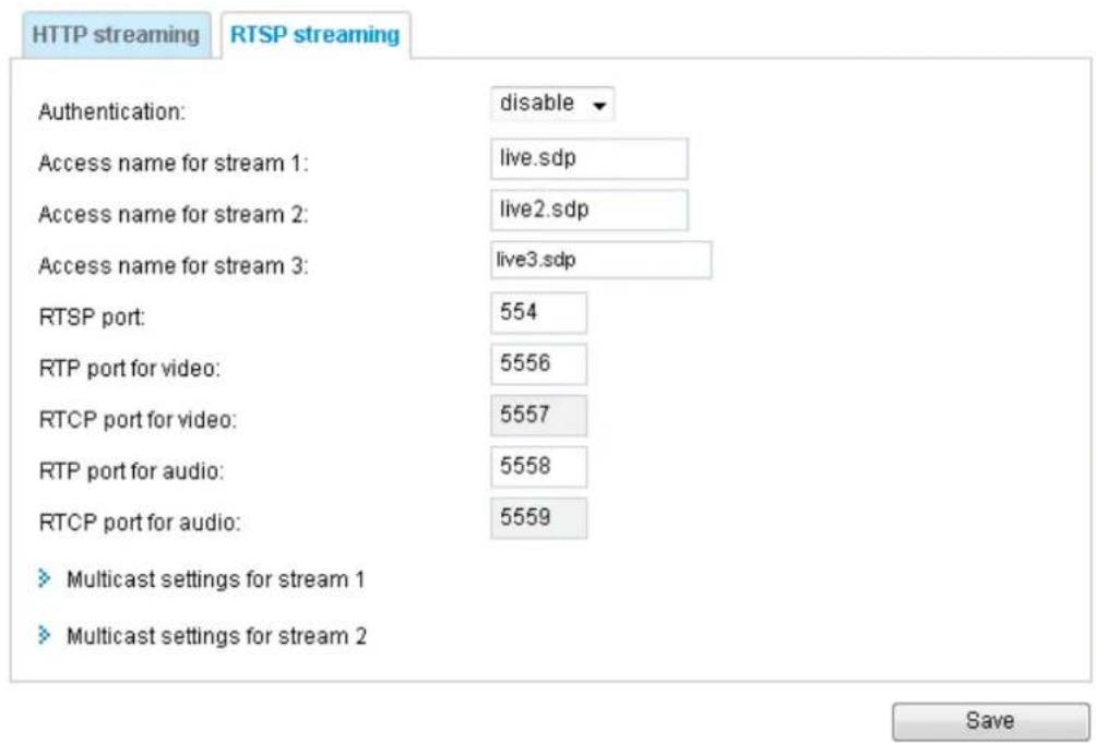
Authentication: Depending on your network security requirements, the Network Camera provides three types of security settings for streaming via RTSP protocol: disable, basic, and digest.
If basic authentication is selected, the password is sent in plain text format, but there can be potential risks of it being intercepted. If digest authentication is selected, user credentials are encrypted using MD5 algorithm, thus providing better protection against unauthorized access.
The availability of the RTSP streaming for the three authentication modes is listed below:
| Quick Time player VLC | ||
| Disable O O | ||
| Basic O O | ||
| Digest O X | ||
Access name for stream 1 \~ 3: This Network camera supports multiple streams simultaneously. The access name is used to differentiate the streaming source.
If you want to use an RTSP player to access the Network Camera, you have to set the video mode to H.264 and use the following RTSP URL command to request transmission of the streaming data.
rtsp://
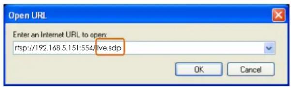
For example, when the access name for stream 1 is set to live.sdp:
-
Launch an RTSP player.
-
Choose File > Open URL. A URL dialog box will pop up.
-
Type the above URL command in the text box.
-
The live video will be displayed in your player as shown below.
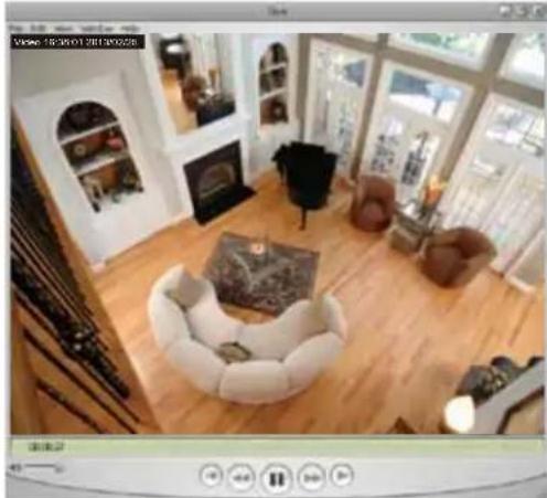
natural_image
Interior view of a modern living room with white sofas, wooden flooring, and large windows (no visible text or symbols)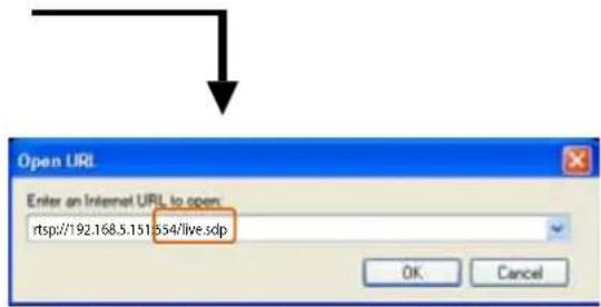
RTSP port /RTP port for video and RTCP port for video
■ RTSP (Real-Time Streaming Protocol) controls the delivery of streaming media. By default, the port number is set to 554.
■ The RTP (Real-time Transport Protocol) is used to deliver video data to the clients. By default, the RTP port for video is set to 5556.
■ The RTCP (Real-time Transport Control Protocol) allows the Network Camera to transmit the data by monitoring the Internet traffic volume. By default, the RTCP port for video is set to 5557.
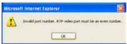
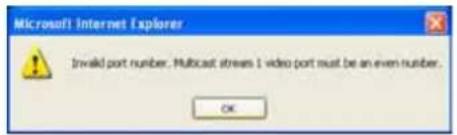
The ports can be changed to values between 1025 and 65535. The RTP port must be an even number and the RTCP port is the RTP port number plus one, and thus is always an odd number. When the RTP port changes, the RTCP port will change accordingly.
If the RTP ports are incorrectly assigned, the following warning message will be displayed:
Multicast settings for stream 1 \~ 3: Click the items to display the detailed configuration information. Select the Always multicast option to enable multicast for stream 1 \~ 3.
![Multicast settings for stream 1 Always multicast Multicast group address: 239.128.1.99 Multicast video port: 5560 Multicast RTCP video port: 5561 Multicast audio port: 5562 Multicast RTCP audio port: 5563 Multicast TTL [1~255]: 15 Multicast settings for stream 2 Always multicast Multicast group address: 239.128.1.100 Multicast video port: 5564 Multicast RTCP video port: 5565 Multicast audio port: 5566 Multicast RTCP audio port: 5567 Multicast TTL [1~255]: 15 Multicast settings for stream 3 Always multicast Multicast group address: 239.128.1.101 Multicast video port: 5568 Multicast RTCP video port: 5569 Multicast audio port: 5570 Multicast RTCP audio port: 5571 Multicast TTL [1~255]: 15](/content/2026/05/1031529/images/c1d0d7c13eb3fb3e473c083aa2c93f30322c458568707c65cd1b9f29334816a2.jpg)
Unicast video transmission delivers a stream through point-to-point transmission; multicast, on the other hand, sends a stream to the multicast group address and allows multiple clients to acquire the stream at the same time by requesting a copy from the multicast group address. Therefore, enabling multicast can effectively save Internet bandwidth.
The ports can be changed to values between 1025 and 65535. The multicast RTP port must be an even number and the multicast RTCP port number is the multicast RTP port number plus one, and thus is always odd. When the multicast RTP port changes, the multicast RTCP port will change accordingly.
If the multicast RTP video ports are incorrectly assigned, the following warning message will be displayed:
Multicast TTL [1\~255]: The multicast TTL (Time To Live) is the value that tells the router the range a packet can be forwarded.
| Initial TTL Scope | |
| 0 Restricted to the same host | |
| 1 Restricted to the same subnetwork | |
| 32 Restricted to the same site | |
| 64 Restricted to the same region | |
| 128 Restricted to the same continent | |
| 255 Unrestricted in scope | |
Network > DDNS
This section explains how to configure the dynamic domain name service for the Network Camera. DDNS is a service that allows your Network Camera, especially when assigned with a dynamic IP address, to have a fixed host and domain name.
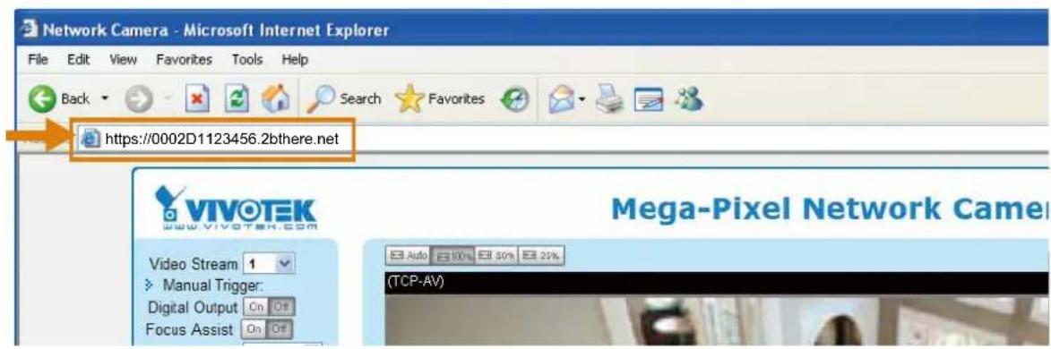
Express link
Express Link is a free service provided by VIVOTEK server, which allows users to register a domain name for a network device. One URL can only be mapped to one MAC address. This service will examine if the host name is valid and automatically open a port on your router. If using DDNS, the user has to manually configure UPnP port forwarding. Express Link is more convenient and easier to set up.
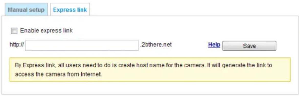
Please follow the steps below to enable Express Link:
- Make sure that your router supports UPnP port forwarding and it is activated.
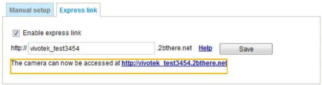
- Check Enable express link.
- Enter a host name for the network device and click Save. If the host name has been used by another device, a warning message will show up. If the host name is valid, it will display a message as shown below.
Manual setup
DDNS: Dynamic domain name service
DDNS: Dynamic domain name service

Enable DDNS:
Provider:
Host name:
User name:
Password:
Dyndns.org(Dynamic)

Enable DDNS: Select this option to enable the DDNS setting.
Provider: Select a DDNS provider from the provider drop-down list.
VIVOTEK offers Safe100.net, a free dynamic domain name service, to VIVOTEK customers. It is recommended that you register Safe100.net to access VIVOTEK's Network Cameras from the Internet. Additionally, we offer other DDNS providers, such as Dyndns.org(Dynamic), Dyndns.org(Custom), TZO.com, DHS.org, CustomSafe100, dyn-interfree.it.
Note that before utilizing this function, please apply for a dynamic domain account first.
■ Safe100.net
- In the DDNS column, select Safe100.net from the drop-down list. Click I accept after reviewing the terms of the Service Agreement.
- In the Register column, fill in the Host name (xxxx.safe100.net), Email, Key, and Confirm Key, and click Register. After a host name has been successfully created, a success message will be displayed in the DDNS Registration Result column.
Register
Host name:
Email:
Key:
Confirm key:
WVTK.safe100.net
wtk@vivotek.com
...
●●●●
Forget key
To apply for a domain name for the camera, or to modify the previously registered information, fill in the following fields and then click "Register".
Register
DDNS Registration Result:
[Register] Successfully Your account information has been mailed to registered e-mail address
Upon successful registration, you can click copy to automatically upload relevant information to the DDNS form or you can manually fill it in. Then, click "Save" to save new settings.
- Click Copy and all the registered information will automatically be uploaded to the corresponding fields in the DDNS column at the top of the page as seen in the picture.
DDNS: Dynamic domain name service
Enable DDNS:
Provider:
Host name:
Email:
Key:
![Safe100.net VVTK.safe100.net wtk@vivotek.com [*.safe100.net]](/content/2026/05/1031529/images/cfcbe1531290c529ea06c1f0417819bbda8525f3b615876396c7ecca27d036a5.jpg)
Save
Register
Host name:
Email:
Key:
Confirm key:
WTK.safe100.net
wtk@vivotek.com
...
...
Forget key
To apply for a domain name for the camera, or to modify the previously registered information, fill in
the following fields and then click "Register".
Register
DDNS Registration Result:
[Register] Successfully Your account information has been mailed to registered e-mail address

Upon successful registration, you can click copy to automatically upload relevant information to the
DDNS form or you can manually fill it in. Then, click "Save" to save new settings.
- Select Enable DDNS and click Save to enable the setting.
■ CustomSafe100
VIVOTEK offers documents to establish a CustomSafe100 DDNS server for distributors and system integrators. You can use CustomSafe100 to register a dynamic domain name if your distributor or system integrators offer such services.
- In the DDNS column, select CustomSafe100 from the drop-down list.
- In the Register column, fill in the Host name, Email, Key, and Confirm Key; then click Register. After a host name has been successfully created, you will see a success message in the DDNS Registration Result column.
- Click Copy and all for the registered information will be uploaded to the corresponding fields in the DDNS column.
- Select Enable DDNS and click Save to enable the setting.
Forget key: Click this button if you have forgotten the key to Safe100.net or CustomSafe100. Your account information will be sent to your email address.
Refer to the following links to apply for a dynamic domain account when selecting other DDNS providers:
■ Dyndns.org(Dynamic) / Dyndns.org(Custom): visit http://www.dyndns.com/
■ dyn-interfree.it: visit http://dyn-interfree.it/
Network > QoS (Quality of Service)
Quality of Service refers to a resource reservation control mechanism, which guarantees a certain quality to different services on the network. Quality of service guarantees are important if the network capacity is insufficient, especially for real-time streaming multimedia applications. Quality can be defined as, for instance, a maintained level of bit rate, low latency, no packet dropping, etc.
The following are the main benefits of a QoS-aware network:
■ The ability to prioritize traffic and guarantee a certain level of performance to the data flow.
■ The ability to control the amount of bandwidth each application may use, and thus provide higher reliability and stability on the network.
Requirements for QoS
To utilize QoS in a network environment, the following requirements must be met:
■ All network switches and routers in the network must include support for QoS.
■ The network video devices used in the network must be QoS-enabled.
QoS models
CoS (the VLAN 802.1p model)
IEEE802.1p defines a QoS model at OSI Layer 2 (Data Link Layer), which is called CoS, Class of Service. It adds a 3-bit value to the VLAN MAC header, which indicates the frame priority level from 0 (lowest) to 7 (highest). The priority is set up on the network switches, which then use different queuing disciplines to forward the packets.
Below is the setting column for CoS. Enter the VLAN ID of your switch (0\~4095) and choose the priority for each application (0\~7).
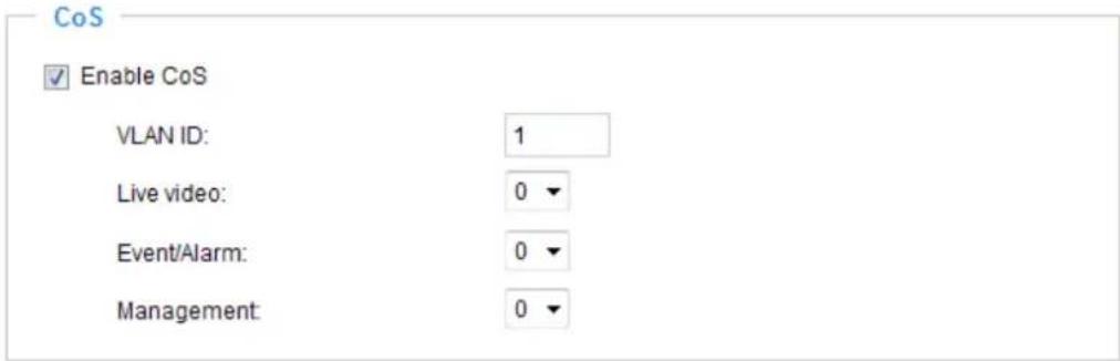
If you assign Video the highest level, the switch will handle video packets first.

NOTE:
▶ A VLAN Switch (802.1p) is required. Web browsing may fail if the CoS setting is incorrect.
The Class of Service technologies do not guarantee a level of service in terms of bandwidth and delivery time; they offer a "best-effort." Users can think of CoS as "coarsely-grained" traffic control and QoS as "finely-grained" traffic control.
▶ Although CoS is simple to manage, it lacks scalability and does not offer end-to-end guarantees since it is based on L2 protocol.
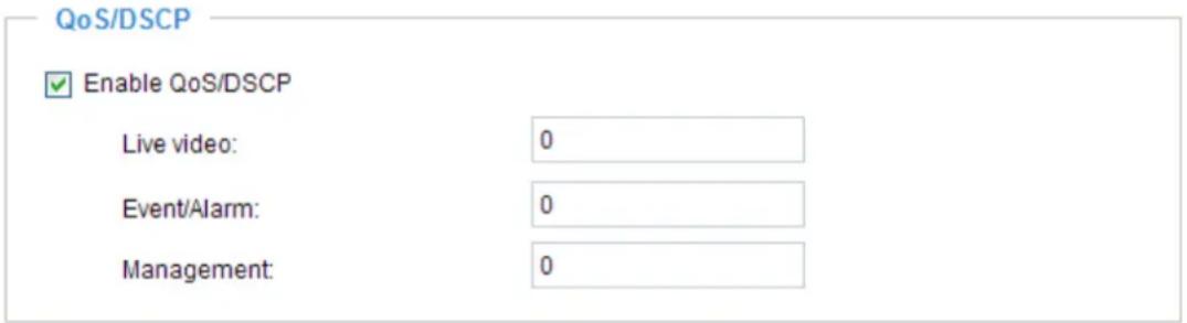
QoS/DSCP (the DiffServ model)
DSCP-ECN defines QoS at Layer 3 (Network Layer). The Differentiated Services (DiffServ) model is based on packet marking and router queuing disciplines. The marking is done by adding a field to the IP header, called the DSCP (Differentiated Services Codepoint). This is a 6-bit field that provides 64 different class IDs. It gives an indication of how a given packet is to be forwarded, known as the Per Hop Behavior (PHB). The PHB describes a particular service level in terms of bandwidth, queueing theory, and dropping (discarding the packet) decisions. Routers at each network node classify packets according to their DSCP value and give them a particular forwarding treatment; for example, how much bandwidth to reserve for it.
Below are the setting options of DSCP (DiffServ Codepoint). Specify the DSCP value for each application (0\~63).
Save
Network > SNMP (Simple Network Management Protocol)
This section explains how to use the SNMP on the network camera. The Simple Network Management Protocol is an application layer protocol that facilitates the exchange of management information between network devices. It helps network administrators to remotely manage network devices and find, solve network problems with ease.
■ The SNMP consists of the following three key components:
- Manager: Network-management station (NMS), a server which executes applications that monitor and control managed devices.
- Agent: A network-management software module on a managed device which transfers the status of managed devices to the NMS.
- Managed device: A network node on a managed network. For example: routers, switches, bridges, hubs, computer hosts, printers, IP telephones, network cameras, web server, and database.
Before configuring SNMP settings on the this page, please enable your NMS first.
SNMP Configuration
Enable SNMPv1, SNMPv2c
Select this option and enter the names of Read/Write community and Read Only community according to your NMS settings.
Enable SNMPv1, SNMPv2c
SNMPv1, SNMPv2c Settings
Read/Write community:
Private
Read only community:
Public
Enable SNMPv3
This option contains cryptographic security, a higher security level, which allows you to set the Authentication password and the Encryption password.
■ Security name: According to your NMS settings, choose Read/Write or Read Only and enter the community name.
■ Authentication type: Select MD5 or SHA as the authentication method.
■ Authentication password: Enter the password for authentication (at least 8 characters).
■ Encryption password: Enter a password for encryption (at least 8 characters).
Enable SNMPv3
SNMPv3 Settings
Read/Write Security name:
Private
Authentication Type:
MD5
Authentication Password:
Encryption Password:
Read only Security name:
Public
Authentication Type:
MD5
Authentication Password:
-
Encryption Password:
Security > User accounts
This section explains how to enable password protection and create multiple accounts.
Root Password

The administrator account name is "root", which is permanent and can not be deleted. If you want to add more accounts in the Manage User column, please apply the password for the "root" account first.
- Type the password identically in both text boxes, then click Save to enable password protection.
- A window will be prompted for authentication; type the correct user's name and password in their respective fields to access the Network Camera.
Privilege Management
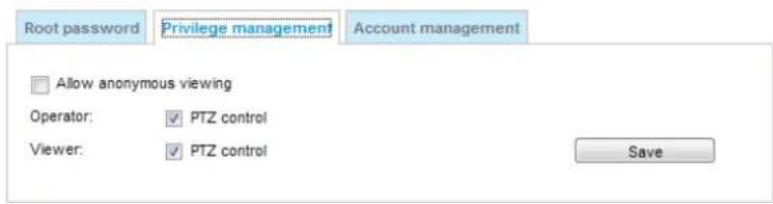
PTZ control: You can modify the management privilege for operators or viewers. Select or deselect the checkboxes, then click Save to enable the settings. If you give Viewers the privilege, Operators will also have the ability to control the Network Camera through the main page. (Please refer to Configuration on page 25).
Allow anonymous viewing: If you check this item, any client can access the live stream without entering a User ID and Password.
Account Management
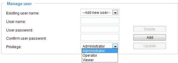
Administrators can create up to 20 user accounts.
- Input the new user's name and password.
- Select the privilege level for the new user account. Click Add to enable the setting.
Access rights are sorted by user privilege (Administrator, Operator, and Viewer). Only administrators can access the Configuration page. Although operators cannot access the Configuration page, they can use the URL Commands to get and set the value of parameters. For more information, please refer to URL Commands of the Network Camera on page 103. Viewers can only access the main page for live viewing.
Here you also can change a user's access rights or delete user accounts.
- Select an existing account to modify.
- Make necessary changes and click Update or Delete to enable the setting.
Security > HTTPS (Hypertext Transfer Protocol over SSL)
This section explains how to enable authentication and encrypted communication over SSL (Secure Socket Layer). It helps protect streaming data transmission over the Internet on higher security level.
Create and Install Certificate Method
Before using HTTPS for communication with the Network Camera, a Certificate must be created first. There are three ways to create and install a certificate:
Create self-signed certificate
- Select this option from a pull-down menu.
- In the first column, select Enable HTTPS secure connection, then select a connection option: "HTTP & HTTPS" or "HTTPS only".
- Click Create certificate to generate a certificate.
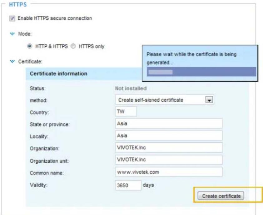
- The Certificate Information will automatically be displayed as shown below. You can click Certificate properties to view detailed information about the certificate.
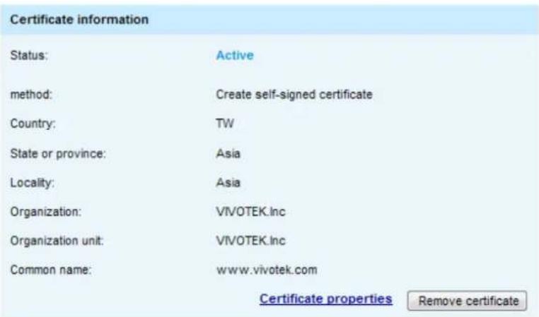
- Click Save to preserve your configuration, and your current session with the camera will change to the encrypted connection.
- If your web session does not automatically change to an encrypted HTTPS session, click Home to return to the main page. Change the URL address from "http://" to "https://" in the address bar and press Enter on your keyboard. Some Security Alert dialogs will pop up. Click OK or Yes to enable HTTPS.
https://
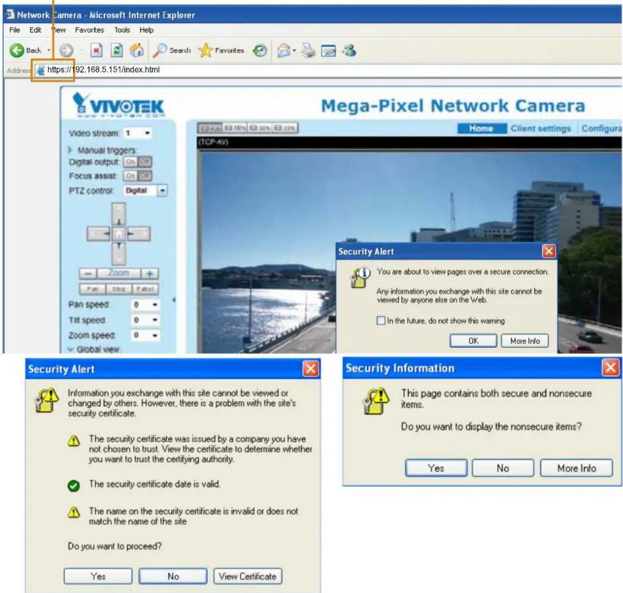
Create certificate request and install
- Select the option from the Method pull-down menu.
- Click Create certificate to proceed.
- The following information will show up in a pop-up window after clicking Create. Then click Save to generate the certificate request.
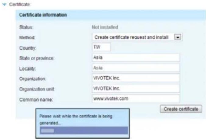
- The Certificate request window will prompt.
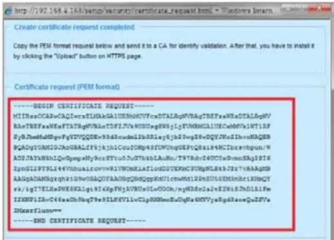
If you see the following Information bar, click OK and click on the Information bar at the top of the page to allow pop-ups.
![HTTPS - Microsoft Internet Explorer File Edit View Favorites Tools Help Back Search Favorites Address http://192.168.5.151 (...wup?https.html) Pop-up blinded. To see the pop-up or additional options click here... VIVOTEK Home Configuration Language VIVOTEK System Security User account HTTPS Access Web IEEE 802.1x Network VIIY > HTTPS Information Bar Did you notice the Information Bar? The Information Bar alerts you when Internet Explorer blocks a pop-up window or file download that might not be safe. If a Web page does not display properly, look for the Information Bar [new the top of your browser]. Do not show this message again. Learn about the Information Bar... OK](/content/2026/05/1031529/images/cfcfc7ffb24e2f04f0d5cd98e4c10a6cb429f35a3a4d20e6558f93bacae074b4.jpg)
- Look for a trusted certificate authority, such as Symantec's VeriSign Authentication Services, that issues digital certificates. Sign in and purchase the SSL certification service. Copy the certificate request from your request prompt and paste it in the CA's signing request window. Proceed with the rest of the process as CA's instructions on their webpage.
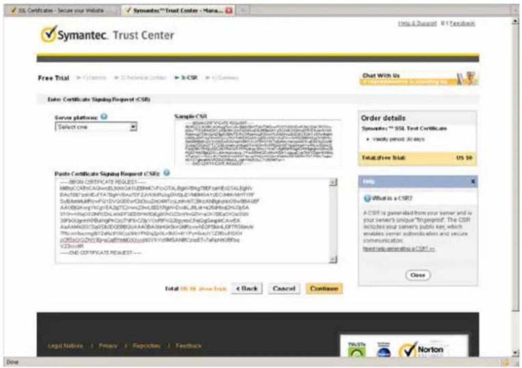
- Once completed, your SSL certificate should be delivered to you via an email or other means. Copy the contents of the certificate in the email and paste it in a text/HTML/hex editor/converter, such as IDM Computer Solutions' UltraEdit.
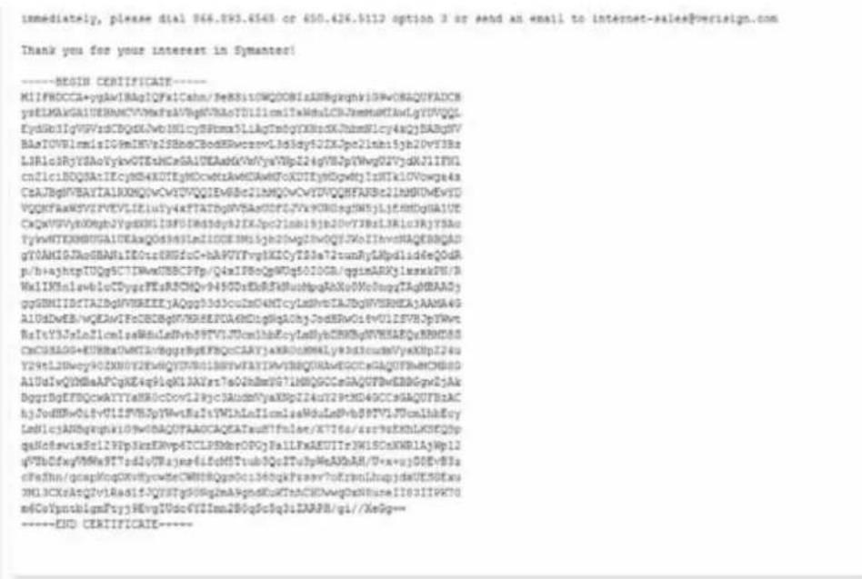
- Open a new edit, paste the certificate contents, and press ENTER at the end of the contents to add an empty line.
![[Edit1*] - UltraEdit File Edit Search Insert Project View Format Complete Window Help Edit1* CmCGSAGG+EUBBxUwBTAvBggrBgEFBQcCARYJaHROcHM6Ly93d3cudnVyaXNpZ24u Y29tLZNvcy90ZXNOYKEwHQYdVR01BBYwFAYIKwYBBQUHAeEGCCsGAQUFBwBCMD0G AiUdIwQYMBaAFCgXE4q91qK13AYst7a02h8mYG71MHQGCCsGAQUFBwEBBCgwZjAk BggrBgEFBQcwAYYYaHROcDovL29jc3AudevVyaXNpZ24uY29tMD40CCsGAQUFBzAC hjJodHRwOiUvU12SVHJpYWetRzItYWlnLnZicmlzaWduLnNbBSPTV1JUcmihbEcy LmN1cjANDgkqhkiG9wOBAQUFAAOCAQEATxuH7FnIae/X7T6z/zsr9zEKbLKSEQSp qaNoHoAwixScI29Pp3kksKKvp6TCLPSNbrCPGjPalLFxAKUITr3WIIBCoXWRlAjWp12 qV5bDbfxgVMWx9T7rd2oURjma61fcMSTtub3Qc2TuJpWeAKbAH/U+X+ojGOEvB3r cPaShn/qdapEcqO0xVBycwHeCWNBRQgmGo1368qKPsmsv7oErbnLhupjdxUESGExu 3M13CXAtQ2v1Rsd1fJQYSTgSONg2mA9ghdKuKTnbCHUwwgOxN8uceIIB3ITFK70 m6CoTpntb1qmFtyj9EvgIUdc6TYImn2BOqSc5q3iTARPH/gi//XeGg== ----END CERTIFICATE----](/content/2026/05/1031529/images/b4d78875c1360c4d0ee5c3416b0068c611c019e3560684f06db4c9ab699573f1.jpg)
- Convert file format from DOS to UNIX. Open File menu > Conversions > DOS to Unix.
![[Edit1*] - UltraEdit File Edit Search Insert Project View Format Column Macro Scripting Advanced Window Help New Ctrl+N Open... Ctrl+O Quick Open... Ctrl+Q Close Close All Files Ctrl+Shift+F4 Close All Files Except Tjys FIP/Telvet Save Ctrl+S Save As... F12 Save All Alt+F12 Make Copy/Backup Encryption Rename File Configure... Alt+F11 Sort Convergs Special Functions Print... Ctrl+P Print All Files Print Preview Print Setup/Configuration Favorite Files... Ctrl+Shift+F Recent Files Recent Projects/WorkSpace Exit 18 20 25 30 35 40 45 50 55 GRAGG+EURBxUwBTAvHggrBgKFBQoCARYJaMROoHNbLy93d3cudmVyaJNpZ24uL2INwcy90TZNOY2EwHQYDVRO1BBTyFAYIKwYBBQUHavEGCCsGAQUFBwMCHB0GdiWQYNBaAPCqXE4q91qK13AYat7a02hSmyT071MHQOCCoGAQUFBwEBBOgwZj)AkRgEFBQcwAYYTaNPDocDovL29jc3AudmVyaJNpZ24uT29tMD4GCCsGAQUFBzACpdHRwOi8vU1ZSVHJpYWvtRsItyVlhlLnZlcmltaWduLmNvbS9TV1JUcm1hbEcycIcjANBgkqhkiIGWwDBAQUFAAOCAQEATxuH7FnIae/X7T6z/zsr9sEKhLKSEQSpcuWixScI29Pp3kxEKVp6TCLPSMbrOPGjPaILFXAEUITr3VlDCoXVR1AjVp12bDfxgVHWx9T7rd2eUIrJsmo61fcN5Tcb3Qc2Tu3pWeAKbAH/U+x+ojGOEvB3sRhn/qcpapKcq02vNyvcWHeCWNBcRqgaGo1368qkPssesv7oXrbnLhupjdxUK3GkxuDCXrAtQ2v1RadifJQYSTg50Nq2mk9ghdEuKTnhCHUwwqOxnBuceIIb3ITPK70eYpntb1qmFtyj9EvgIUdc6YZImn2BOq8c5q3iZARPH/gi//Xe0g-- --END CERTIFICATE---- UNDS/MAC to DOS DOS to MAC DOS to UNDX CDCDC to ASCII ASCII to CDCDC OEM to AIGI ANSI to OEM ASCII to Unicode UTF8 to Unicode Universe to ASCII template List Global Power User](/content/2026/05/1031529/images/fd9991a0b4847f1430af6612b34e2ee70818bb8478c7923f97c6555ecc9269cf.jpg)
- Save the edit using the ".crt" extension, using a file name like "CAcert.crt."
![[C:\Documents and Settings\weabs\Desktop\Editcrt*]: LIFcads File Edit Search Insert Project View Format Columns Place Ordering Advanced Windows Help Save As Project Open Explorer Lists Filter: A: C: D: E: F: Network FTP Accounts Save in: Desktop My Documents. My Computer My Network Places Adobe Reader 9 File26a Client Google Chrome Installation Wizard 2 LiveClient McAfee Security Scan Plus Milestone xProtect Smart Client Mozilla Firefox Playback QuickTime Player RealPlayer TeamViewer 6 UltraCompare UltraEdit VIVOTEX BlackholePM公用资料文 (位於 Blackhole) New Folder 44 45 46 802.1x 802.1x-1 802.1x-2 802.1x-3 access_alert activeX_plugin activeX_plugin1 File name: CAcert.cs Save as type: All Files (*.*) Line Termination: Default Format: Default ADS Stream: Save Cancel Output Window B7U 1 2](/content/2026/05/1031529/images/702d5ec95def9508c84d2eb972a0cc0acdc9576629f381dc9b79f2b977563005.jpg)
- Return to the original firmware session, use the Browse button to locate the crt certificate file, and click Upload to enable the certification.
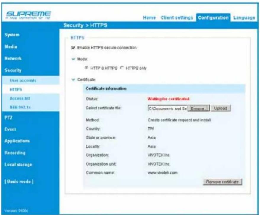
- When the certificate file is successfully loaded, its status will be stated as Active. Note that a certificate must have been created and installed before you can click on the "Save" button for the configuration to take effect.
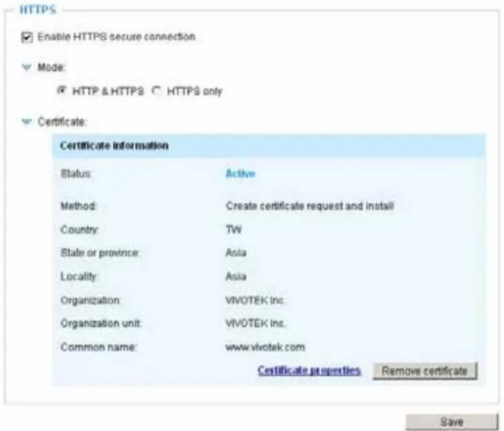
- To begin an encrypted HTTPS session, click Home to return to the main page. Change the URL address from "http://" to "https://" in the address bar and press Enter on your keyboard. Some Security Alert dialogs will pop up. Click OK or Yes to enable HTTPS.
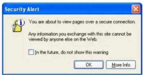
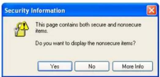
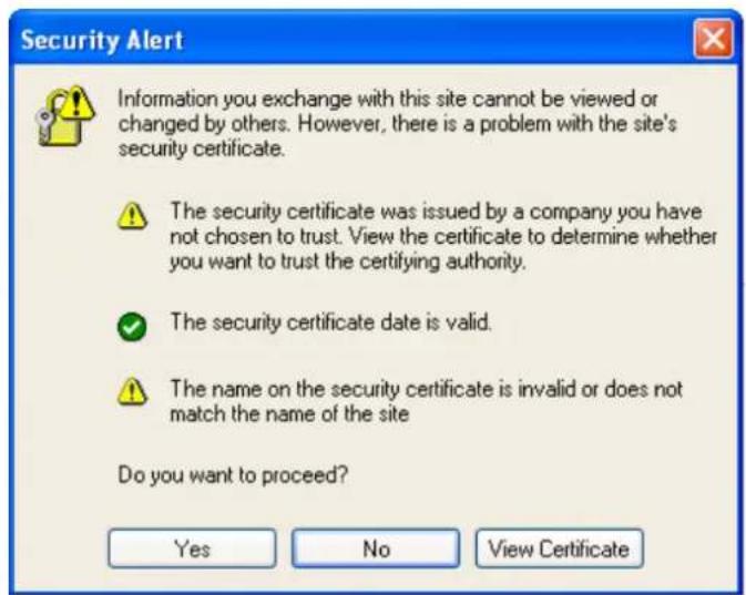
Security > Access List
This section explains how to control access permission by verifying the client PCs' IP addresses.
General Settings

Maximum number of concurrent streaming connection(s) limited to: Simultaneous live viewing for 1\~10 clients (including stream 1 to stream 3). The default value is 10. If you modify the value and click Save, all current connections will be disconnected and automatically attempt to re-link (IE Explorer or Quick Time Player).
View Information: Click this button to display the connection status window showing a list of the current connections. For example:
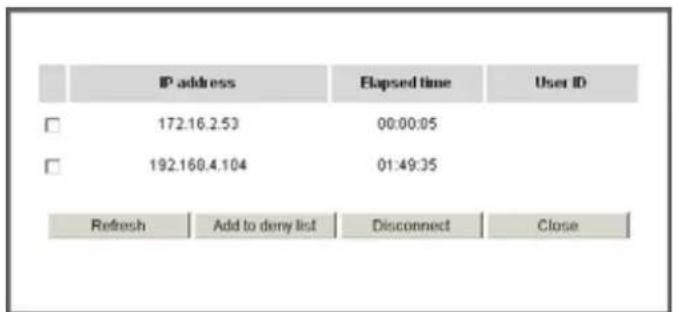
Note that only consoles that are currently displaying live streaming will be listed in the View Information list.
■ IP address: Current connections to the Network Camera.
■ Elapsed time: How much time the client has been at the webpage.
■ User ID: If the administrator has set a password for the webpage, the clients have to enter a user name and password to access the live video. The user name will be displayed in the User ID column. If the administrator allows clients to link to the webpage without a user name and password, the User ID column will be empty.
There are some situations that allow clients access to the live video without a user name and password:
- The administrator does not set up a root password. For more information about how to set up a root password and manage user accounts, please refer to Security > User account on page 62.
- The administrator has set up a root password, but set RTSP Authentication to "disable". For more information about RTSP Authentication, please refer to RTSP Streaming on page 53.
- The administrator has set up a root password, but allows anonymous viewing. For more information about Allow Anonymous Viewing, please refer to page 62.
■ Refresh: Click this button to refresh all current connections.
■ Add to deny list: You can select entries from the Connection Status list and add them to the Deny List to deny access. Please note that those checked connections will only be disconnected temporarily and will automatically try to re-link again (IE Explore or Quick Time Player). If you want to enable the denied list, please check Enable access list filtering and click Save in the first column.
■ Disconnect: If you want to break off the current connections, please select them and click this button. Please note that those checked connections will only be disconnected temporarily and will automatically try to re-link again (IE Explore or Quick Time Player).
Filter
Enable access list filtering: Check this item and click Save if you want to enable the access list filtering function.
Filter type: Select Allow or Deny as the filter type. If you choose Allow Type, only those clients whose IP addresses are on the Access List below can access the Network Camera, and the others cannot. On the contrary, if you choose Deny Type, those clients whose IP addresses are on the Access List below will not be allowed to access the Network Camera, and the others can.
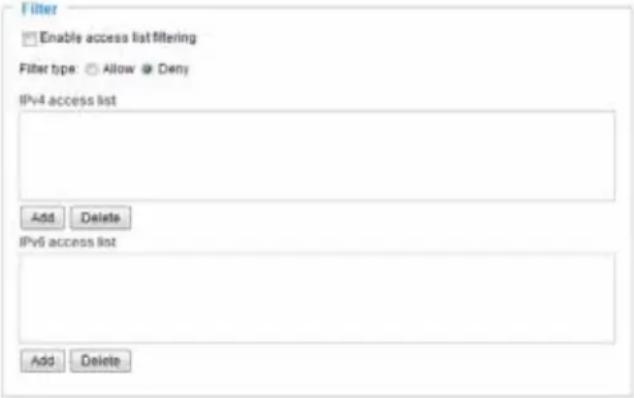
Then you can Add a rule to the following Access List. Please note that the IPv6 access list column will not be displayed unless you enable IPv6 on the Network page. For more information about IPv6 Settings, please refer to Network > General settings on page 49 for detailed information.
There are three types of rules:
Single: This rule allows the user to add an IP address to the Allowed/Denied list.
For example:
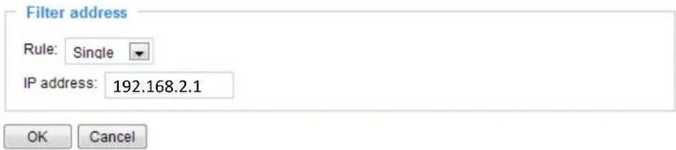
Network: This rule allows the user to assign a network address and corresponding subnet mask to the Allow/Deny List. The address and network mask are written in CIDR format.
For example:
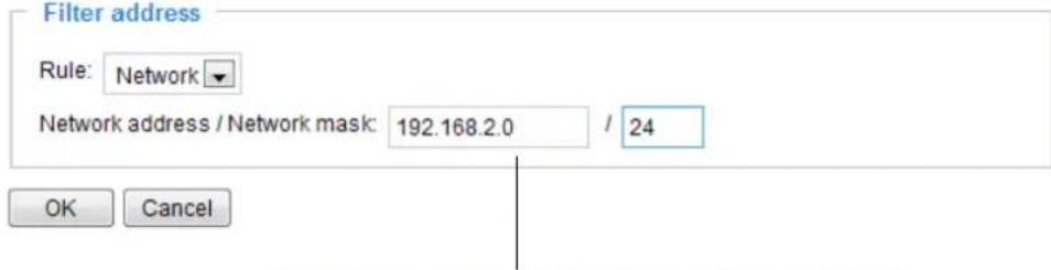
IP address range 192.168.2.x will be bolcked.
If IPv6 filter is preferred, you will be prompted by the following window. Enter the IPv6 address and the two-digit prefix length to specify the range of IP addresses in your configuration.
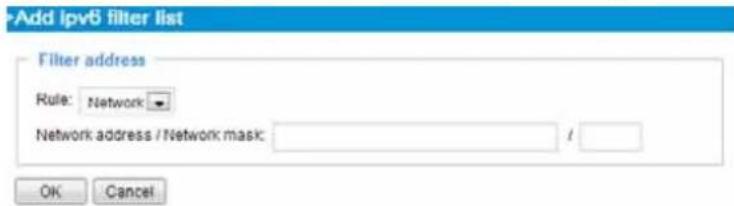
Range: This rule allows the user to assign a range of IP addresses to the Allow/Deny List. Note: This rule only applies to IPv4 addresses.
For example:
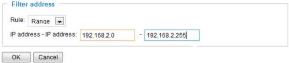
Administrator IP address
Always allow the IP address to access this device: You can check this item and add the Administrator's IP address in this field to make sure the Administrator can always connect to the device.

Security > IEEE 802.1X
Enable this function if your network environment uses IEEE 802.1x, which is a port-based network access control. The network devices, intermediary switch/access point/hub, and RADIUS server must support and enable 802.1x settings.
The 802.1x standard is designed to enhance the security of local area networks, which provides authentication to network devices (clients) attached to a network port (wired or wireless). If all certificates between client and server are verified, a point-to-point connection will be enabled; if authentication fails, access on that port will be prohibited. 802.1x utilizes an existing protocol, the Extensible Authentication Protocol (EAP), to facilitate communication.
■ The components of a protected network with 802.1x authentication:
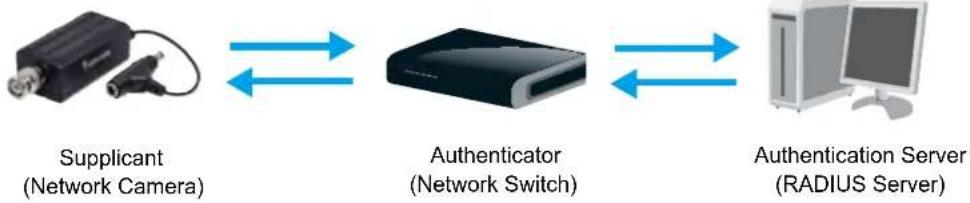
flowchart
graph LR
    A["Supplicant\n(Network Camera)"] <--> B["Authenticator\n(Network Switch)"]
    B <--> C["Authentication Server\n(RADIUS Server)"]
- Supplicant: A client end user (camera), which requests authentication.
- Authenticator (an access point or a switch): A "go between" which restricts unauthorized end users from communicating with the authentication server.
- Authentication server (usually a RADIUS server): Checks the client certificate and decides whether to accept the end user's access request.
■ VIVOTEK Network Cameras support two types of EAP methods to perform authentication: EAP-PEAP and EAP-TLS.
Please follow the steps below to enable 802.1x settings:
- Before connecting the Network Camera to the protected network with 802.1x, please apply a digital certificate from a Certificate Authority (i.e., your network administrator) which can be validated by a RADIUS server.
- Connect the Network Camera to a PC or notebook outside of the protected LAN. Open the configuration page of the Network Camera as shown below. Select EAP-PEAP or EAP-TLS as the EAP method. In the following blanks, enter your ID and password issued by the CA, then upload related certificate(s).
IEEE 802.1x

Enable IEEE 802.1x
EAP method:
Identity:
Password:
CA certificate:
Status: no file
EAP-PEAP

Remove

IMPORTANT
The maximum length of password is 200 symbols.
IEEE 802.1x
Enable 802.1x
EAP method:
Identity:
Private key passord:
CA certificate:
Status: no file
client certificate:
Status: no file
Client private key:
Status: no file
EAP-TLS


Browse..
广力云智慧零售收银系统
Browse..
[Non-Text]
Browse..
[Non-Text]
Upload
广力云智慧零售收银系统
Upload
广力云智慧零售收银系统
Upload
- When all settings are complete, move the Network Camera to the protected LAN by connecting it to an 802.1x enabled switch. The devices will then start the authentication automatically.

NOTE:
▶ The authentication process for 802.1x:
- The Certificate Authority (CA) provides the required signed certificates to the Network Camera (the supplicant) and the RADIUS Server (the authentication server).
- A Network Camera requests access to the protected LAN using 802.1X via a switch (the authenticator). The client offers its identity and client certificate, which is then forwarded by the switch to the RADIUS Server, which uses an algorithm to authenticate the Network Camera and returns an acceptance or rejection back to the switch.
- The switch also forwards the RADIUS Server's certificate to the Network Camera.
- Assuming all certificates are validated, the switch then changes the Network Camera's state to authorized and is allowed access to the protected network via a pre-configured port.
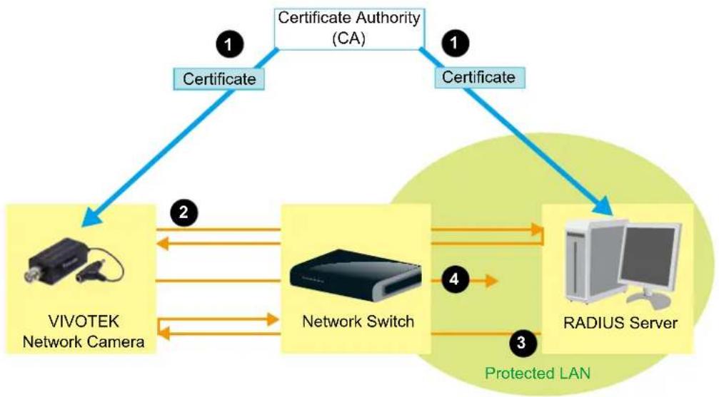
flowchart
graph TD
    A["Certificate Authority (CA)"] -->|1| B["VIVOTEK Network Camera"]
    A -->|1| C["Certificate"]
    B <--> D["Network Switch"]
    C <--> E["RADIUS Server"]
    D <--> F["Protected LAN"]
    E <--> F
PTZ > PTZ settings
This section explains how to control the Network Camera's Pan/Tilt/Zoom operation by connecting to a PTZ driver or scanner via RS485 interface. Before configuration, connect the video server to a PTZ camera or PTZ scanner via RS485 interface.
RS485 settings
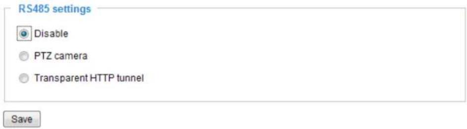
Disable: Select this option to disable this function.
PTZ camera: Select this option to enable PTZ operation.
To utilize this feature, please connect the Network Camera to a PTZ camera or PTZ scanner via RS485 interface first. Then you can configure the PTZ driver and RS485 port with the following settings.
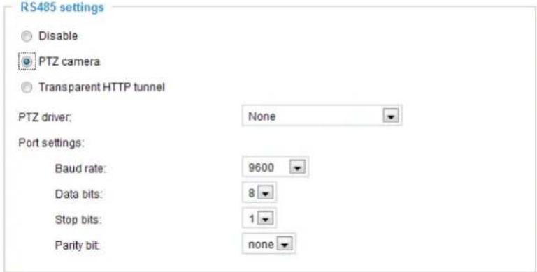
VIVOTEK provides several PTZ drivers: DynaDome/SmartDOME, Lilin PIH-7x00, Pelco D, Pelco P, and Samsung Scc643 protocol. If none of the above PTZ drivers is supported by your PTZ scanner, please select Custom camera (scanner). Please refer to the user's manual of your PTZ scanner to determine the Camera ID, PTZ driver, and Port settings. The Camera ID is necessary to control multiple cameras. If you click Save to enable this function, the camera control panel will be displayed on the main page. Please refer to the illustration on page 80.
Transparent HTTP Tunnel: If you want to use your own RS-485 device, you can use UART commands to build a Transparent HTTP Tunnel. The UART commands will be sent through HTTP tunnel established between the RS-485 device and the linked camera. For detailed application notes, please refer to URL Commands on page 103 or the FAQ pages on VIVOTEK's website.

Port settings:
Baud rate:
Data bits:
Stop bits:
Parity bit:
Preset positions
If you select DynaDome/SmartDOME, Lilin PIH-7x00, or Pelco D, Pelco P protocol, Samsung scc643 protocol protocol as the PTZ driver and click the Save button, the Preset Position button will be enabled. Click Preset Position to open the settings page. You can also select preset positions for the camera to patrol. A total of 20 preset positions can be configured.
Please follow the steps below to preset a position:
- Select Channel in the drop-down list.
- Adjust the shooting area to the desired position by using the buttons on the right. The default Home position is set as the center position.
- Enter a name for the preset position, which allows up to forty characters. Click Add to enable the settings. The preset positions will be displayed under User preset locations.
- To add additional preset positions, please repeat steps 1\~2.
- Select the preset positions and click on Save to enable the settings.
- The positions saved will show up in Go to drop down list on the Home page. See next page
- To remove a preset position from the list, select it and click Remove.
1
Channel: 1
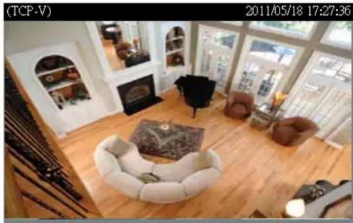
natural_image
Interior view of a modern living room with wooden flooring, white furniture, and large windows (no visible text or symbols)2
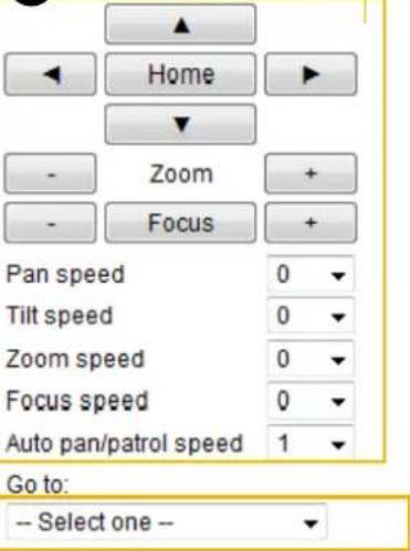
6
3
Preset and patrol settings
Name: Add preset location
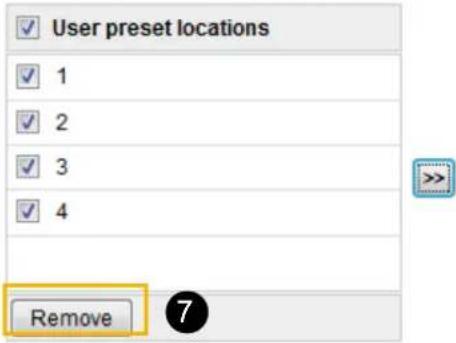
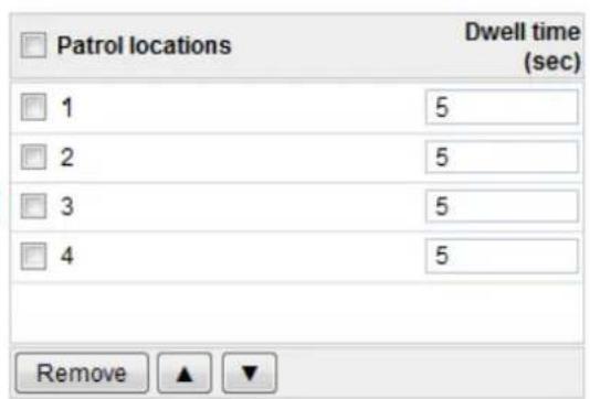
5

■ The Camera Control Panel and Preset positions will be displayed on the home page:
- Click Go to: Select one from the drop-down list, and the Network Camera will move to the selected preset position.
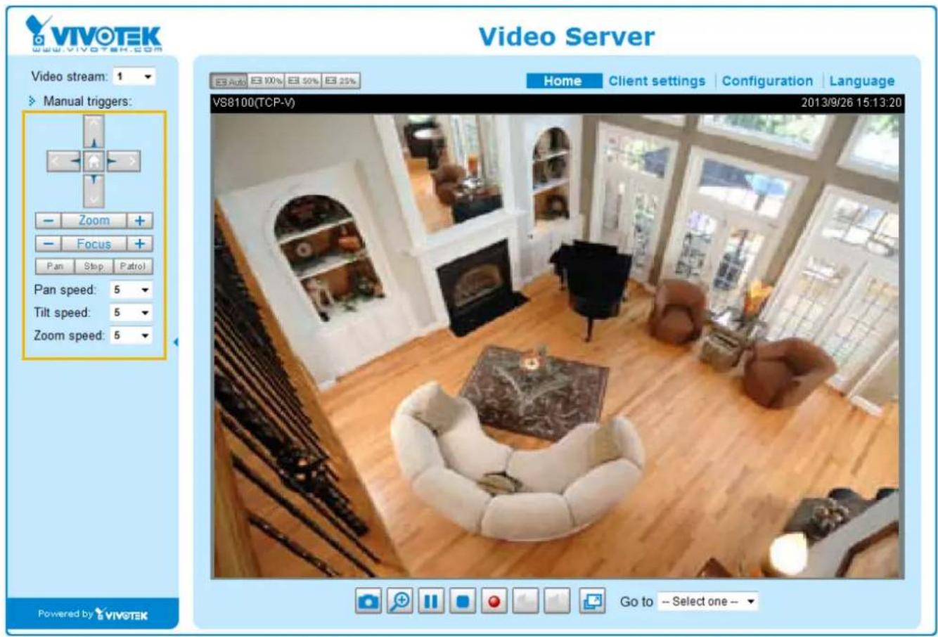
Camera ID settings
The Camera ID is necessary to control multiple cameras. If you click Save to enable this function, the camera control panel will be displayed on the main page.
Patrol settings
You can select some preset positions for the Network Camera to patrol.
Please follow the steps below to set up a patrol schedule:
- Select Channel in the drop-down list.
- Select the preset locations on the list, and click >>.
- The selected preset locations will be displayed on the Patrol locations list.
- Set the Dwelling time for the preset location during auto patrol.
- If you want to delete a preset location from the Patrol locations list, select it and click Remove.
- Select a location and click ▲ ▼ to rearrange the patrol order.
- Select patrol locations you want to save in the list and click Save to enable the patrol settings.
- To implement the patrol schedule, please go to homepage and click on Patrol button.
1 Channel: 1 ▼
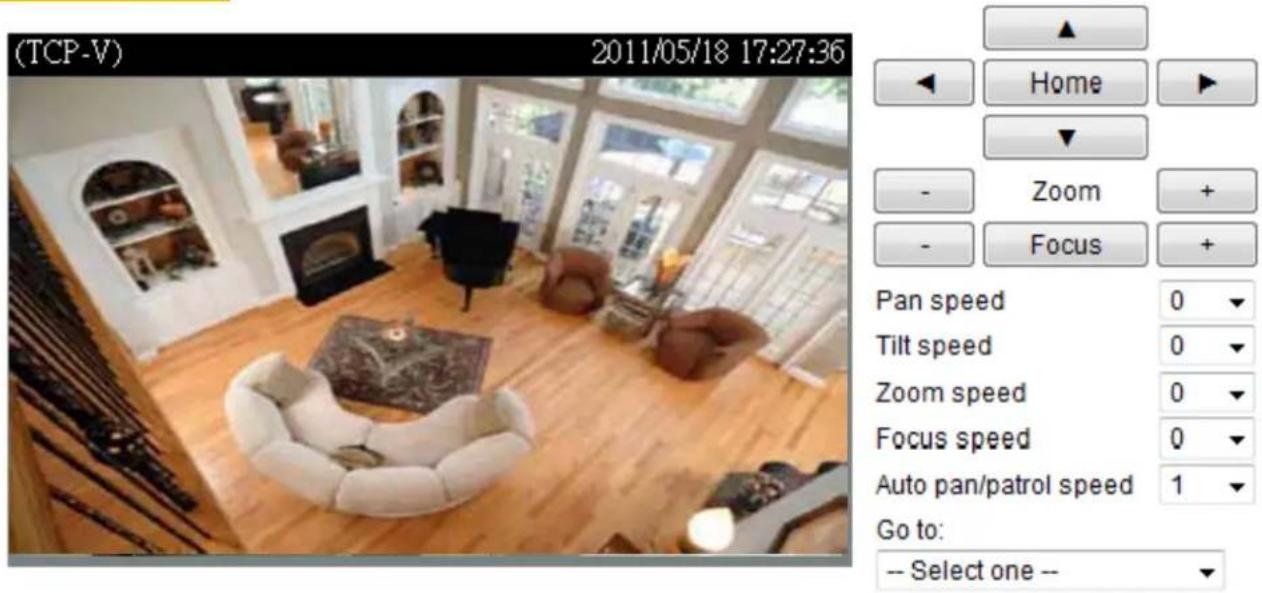
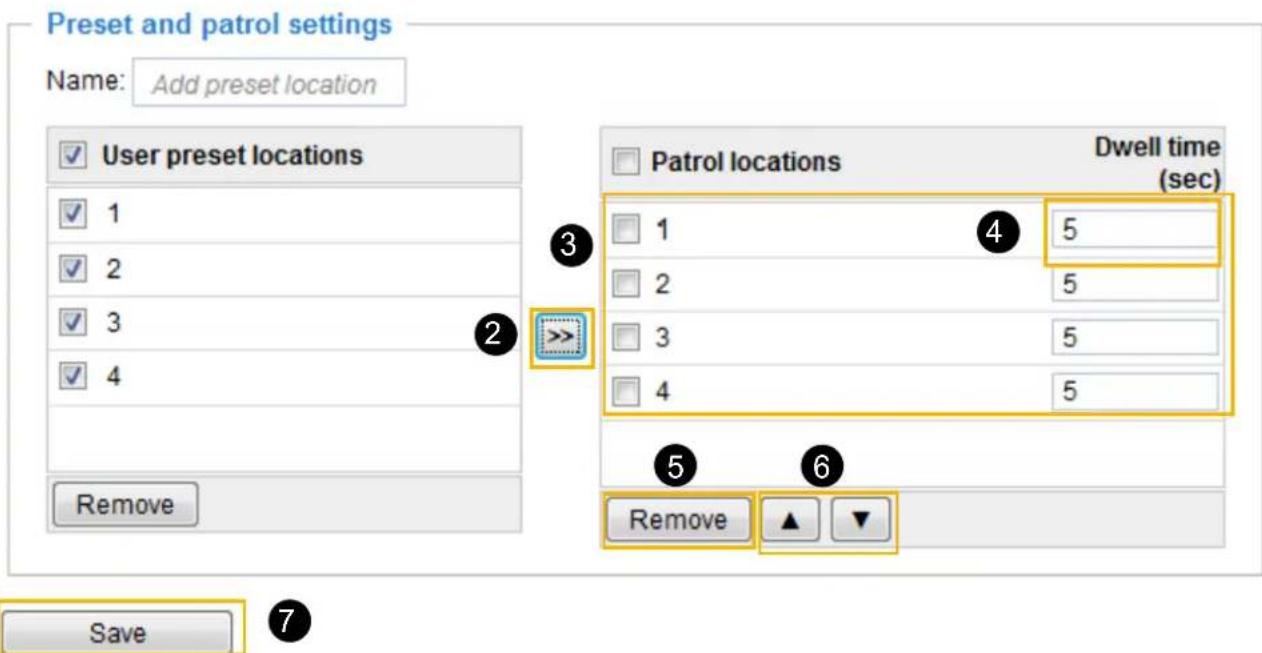
Custom Command
If Custom Camera (scanner) is selected as the PTZ driver, the Preset Position and PTZ Control Panel on the main page will be disabled. You will need to configure command buttons to control the PTZ scanner. Click Custom Command to open the Custom Command page to set the commands in the Control Settings session. Please refer to your PTZ scanner user's manual to enter the commands in the following fields. Click Save to enable the settings and click Close to exit the page.
Control settings
| Up | |
| Down | |
| Left | |
| Right | |
| Home | |
| Zoom in | |
| Zoom out | |
| Focus closer | |
| Focus further | |
| Auto focus |
Custom command
| Button name | Command | |
| Command 1: | right | |
| Command 2: | left | |
| Command 3: | home | |
| Command 4: | top | |
| Command 5: | low |
| Save | Close |

NOTE:
▶ If you select DynaDome/SmartDOME, Lilin PIH-7x00, or Pelco D protocol as the PTZ driver, the Control Settings column will not be displayed.
▶ For all PTZ drivers, a total of five additional command buttons can be configured.
▶ The command buttons will be displayed on the main page:
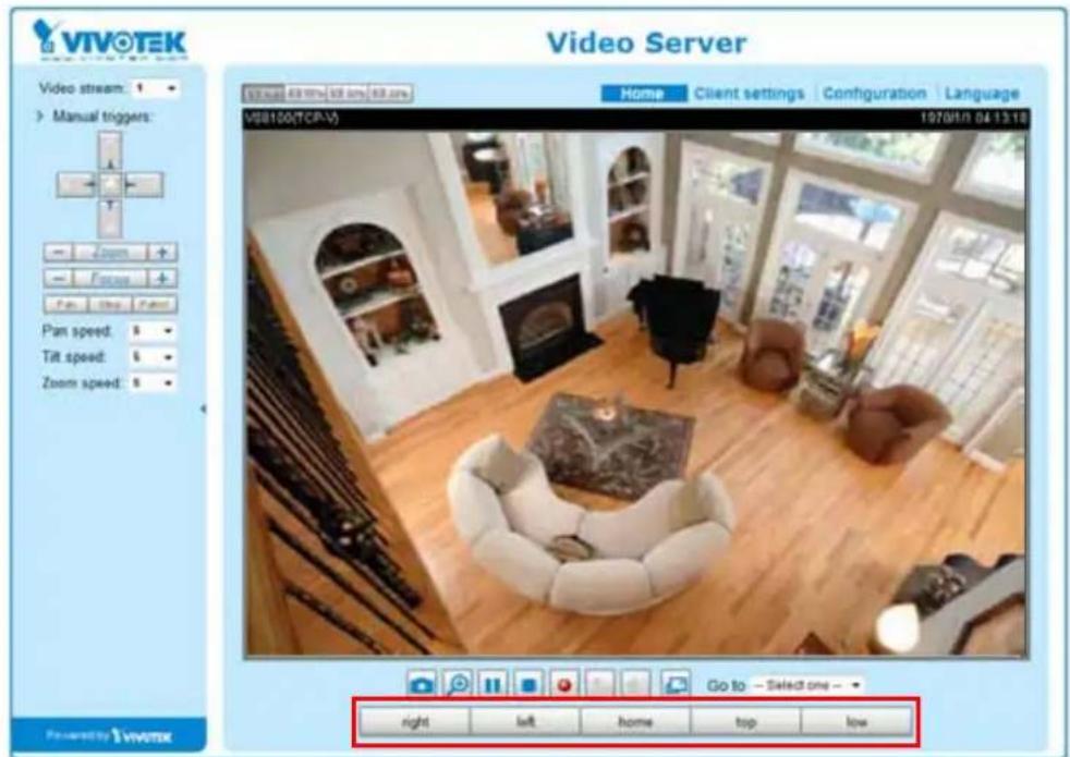
Event > Event settings
Advanced Mode
This section explains how to configure the Network Camera to responds to particular situations (event). A typical application is that when a motion is detected, the Network Camera sends buffered images to an FTP server or e-mail address as notifications. Click on Help, there is an illustration shown in the pop-up window explaining that an event can be triggered by many sources, such as motion detection or external digital input devices. When an event is triggered, you can specify what type of action that will be performed. You can configure the Network Camera to send snapshots or videos to your email address or FTP site.
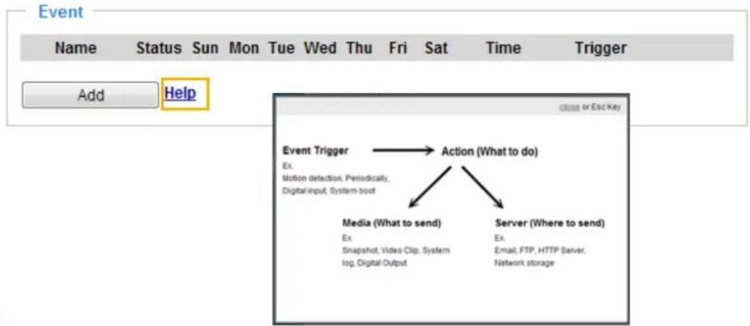
Event
To configure an event with reactive measures such as recording video or snapshots, it is necessary to configure the server and media settings so that the Network Camera will know what action to take (such as which server to send the media files to) when a trigger is activated. An event is an action initiated by a user-defined trigger source. In the Event column, click Add to open the event settings window. Here you can arrange three elements -- Schedule, Trigger, and Action to set an event. A total of 3 event settings can be configured.
![Event Name Status Sun Mon Tue Wed Thu Fri Sat Time Trigger Add Help Event name: Enable this event Priority Normal Detect next motion detection or digital input after 10 second(s) 1. Schedule 2. Trigger 3. Action Event Schedule Sun Mon Tue Wed Thu Fri Sat Time Always From 00:00 to 24:00 [hh.mm] Close Save event](/content/2026/05/1031529/images/46544d6a2e04cd2749a08d7a00656cdbf64bbcc0f6f5871d0aef8b9da1084cc1.jpg)
■ Event name: Enter a name for the event setting.
■ Enable this event: Select this option to enable the event setting.
■ Priority: Select the relative importance of this event (High, Normal, or Low). Events with a higher priority setting will be executed first.
■ Detect next event after □ seconds: Enter the duration in seconds to pause motion detection after a motion is detected. This can prevent event-related actions to take place too frequently.
1. Schedule
Specify the period of them during which the event trigger will take effect. Please select the days of the week and the time in a day (in 24-hr time format) for the event triggering schedule. For example, you may prefer an event to be triggered only during the off-office hours.
2. Trigger
This is the cause or stimulus which defines when to trigger the Network Camera. The trigger source can be configured to use the Network Camera's built-in motion detection mechanism or external digital input devices.
There are several choices of trigger sources as shown on the next page. Select the item to display the detailed configuration options.
■ Video motion detection
This option makes use of the built-in motion detection mechanism as a trigger source. To enable this function, you need to configure a Motion Detection Window first. For more information, please refer to Motion Detection on page 94 for details.
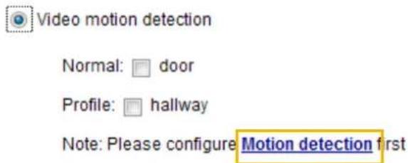
■ Periodically
This option allows the Network Camera to trigger periodically for every other defined minute. Up to 999 minutes are allowed.

■ System boot
This option triggers the Network Camera when the power to the Network Camera is disconnected and re-connected.
■ Recording notify
This option allows the Network Camera to trigger when the recording disk is full or when recording starts to overwrite older data.
■ Camera tampering detection
This option allows the Network Camera to trigger when the camera detects that is is being tampered with. To enable this function, you need to configure the Tampering Detection option first. Please refer to page 97 for detailed information.
![Camera tampering detection Enable camera tampering detection Trigger duration: 10 seconds [10-600] Save](/content/2026/05/1031529/images/8e80422ceb3a92737d6b2408e9c61d3a240a0ee4065c302dbec4ff5c6ba827c1.jpg)
■ Manual Trigger
This option allows users to enable event triggers manually by clicking the on/off button on the homepage. Please configure 1 to 3 associated events before using this function.

■ Video loss: triggers an event when video transaction is discontinued.
■ Video restore: triggers an event when video transaction is re-established.
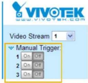
3. Action
Define the actions to be performed by the Network Camera when a trigger is activated.
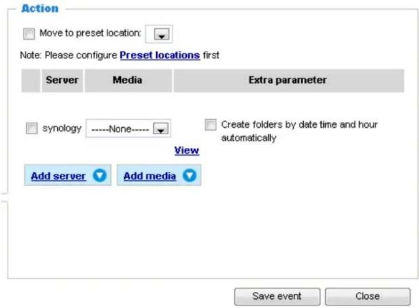
Add server
It is necessary to configure the server and media settings so that the Network Camera will know what action to take (such as which server to send the media files to) when a trigger is activated. Click Add server to open the server setting window. You can specify where the notification messages are sent to when a trigger is activated. A total of 5 server settings can be configured.
There are four choices of server types available: Email, FTP, HTTP, and Network storage. Select the item to display the detailed configuration options. You can configure either one or all of them.
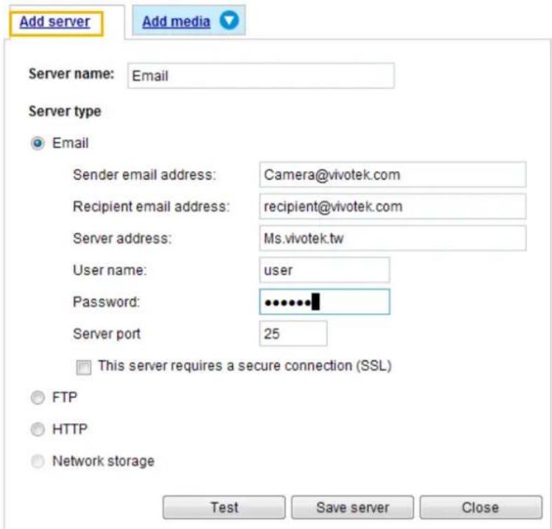
Server type - Email
Select to send the media files via email when a trigger is activated.
■ Server name: Enter a name for the server setting.
■ Sender email address: Enter the email address of the sender.
■ Recipient email address: Enter the email address of the recipient.
■ Server address: Enter the domain name or IP address of the email server.
■ User name: Enter the user name of the email account if necessary.
■ Password: Enter the password of the email account if necessary.
■ Server port: The default mail server port is set to 25. You can also manually set another port.
If your SMTP server requires a secure connection (SSL), select This server requires a secure connection (SSL).
To verify if the email settings are correctly configured, click Test. The result will be shown in a pop-up window. If successful, you will also receive an email indicating the result.
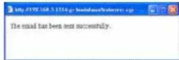
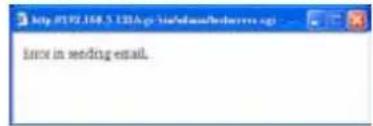
Click Save server to enable the settings.
Note that after you configure the first event server, the new event server will automatically display on the Server list. If you wish to add other server options, click Add server.
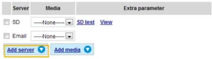
Server type - FTP
Select to send the media files to an FTP server when a trigger is activated.
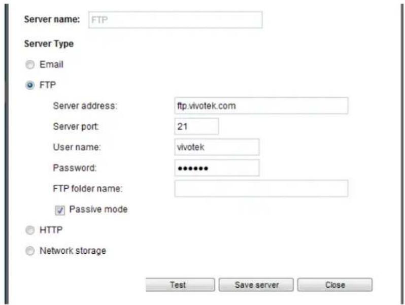
■ Server name: Enter a name for the server setting.
■ Server address: Enter the domain name or IP address of the FTP server.
■ Server port: By default, the FTP server port is set to 21. It can also be assigned to another port number between 1025 and 65535.
■ User name: Enter the login name of the FTP account.
■ Password: Enter the password of the FTP account.
■ FTP folder name
Enter the folder where the media files will be placed. If the folder name does not exist, the Network Camera will automatically create one on the FTP server.
■ Passive mode
Most firewalls do not accept new connections initiated from external requests. If the FTP server supports passive mode, select this option to enable passive mode FTP and allow data transmission to pass through the firewall. The firmware default has the Passive mode checkbox selected.
To verify if the FTP settings are correctly configured, click Test. The result will be shown in a pop-up window as shown below. If successful, you will also receive a test.txt file on the FTP server.

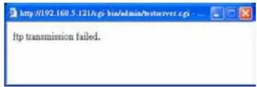
Click Save server to enable the settings.
Server type - HTTP
Select to send the media files to an HTTP server when a trigger is activated.
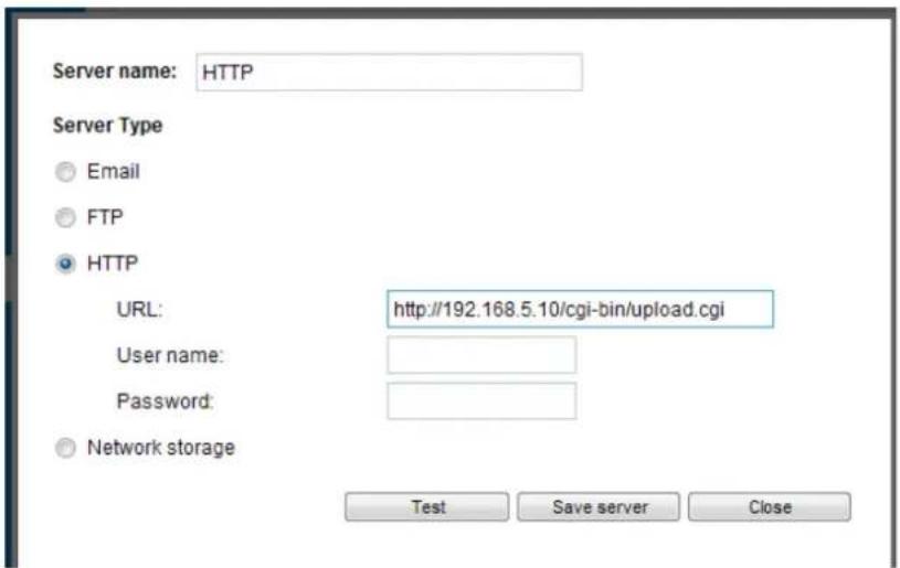
■ Server name: Enter a name for the server setting.
■ URL: Enter the URL of the HTTP server.
■ User name: Enter the user name if necessary.
■ Password: Enter the password if necessary.
To verify if the HTTP settings are correctly configured, click Test. The result will be shown in a pop-up window as shown below. If successful, you will receive a test.txt file on the HTTP server.
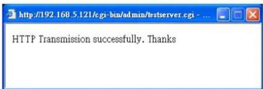
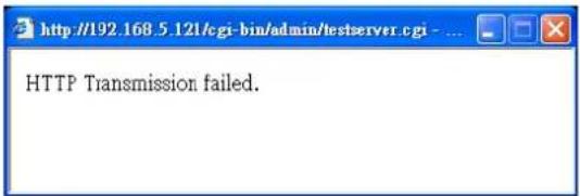
Click Save server to enable the settings.
Network storage:
Select to send the media files to a networked storage when a trigger is activated. Please refer to NAS server on page 100 for details. Note that only one NAS server can be configured.
Click Save server to enable the settings.
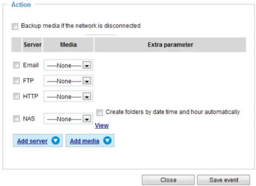
■ View: Click this button to open a file list window. This function is only for Networked Storage. If you click the View button, a storage share's page will prompt so that you can manage the recorded files on it. A file directory window will prompt for you to view recorded data on Networked storage. For detailed illustration, please refer to the next page.
■ Create folders by date, time, and hour automatically: If you select this item, the system will automatically create folders by the date when video footages are stored onto the networked storage.
The following is an example of a file destination with video clips:
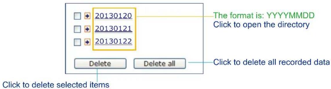
Click 20130120 to open the directory:
The format is: HH (24r)
Click to open the file list for that hour
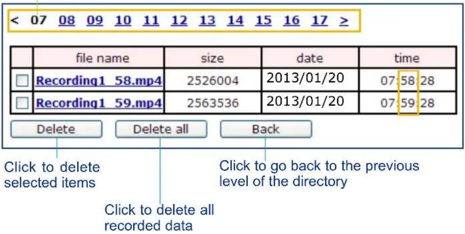
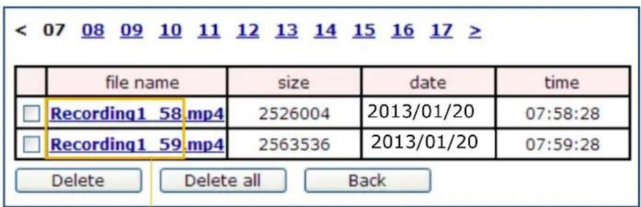
The format is: File name prefix + Minute (mm)
You can set up the file name prefix on Add media page. Please refer to next page for detailed information.
Add media
Click Add media to open the media setting window. You can specify the type of media that will be sent when a trigger is activated. A total of 5 media settings can be configured. There are three choices of media types available: Snapshot, Video Clip, and System log. Select the item to display the detailed configuration options. You can configure either one or all of them.
![Add server Add media Media name: Media type Attached media: Snapshot Source: Stream 1 Send 1 pre-event image(s) [0~7] Send 1 post-event image(s) [0~7] File name prefix: Snapshot_ ✓ Add date and time suffix to file name Video clip System log Save media Close](/content/2026/05/1031529/images/b8346bb8aef285c714d3ad266d9fb43438e275524a370d4a057bcec40d09e3f1.jpg)
Media type - Snapshot
Select to send snapshots when a trigger is activated.
■ Media name: Enter a name for the media setting.
■ Source: Select to take snapshots from any of the video streams.
■ Send □ pre-event images
The Network Camera has a buffer to temporarily hold data for a short period of time. Enter a number to decide how many images to capture before a trigger is activated. Up to 7 images can be generated.
■ Send □ post-event images
Enter a number to decide how many images to capture after a trigger is activated. Up to 7 images can be generated.
For example, if both the Send pre-event images and Send post-event images are set to 7, a total of 15 images can be generated after a trigger is activated.
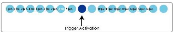
■ File name prefix
Enter the text that will be appended to the front of the file name.
■ Add date and time suffix to the file name
Select this option to add a date/time suffix to the file name.
For example:
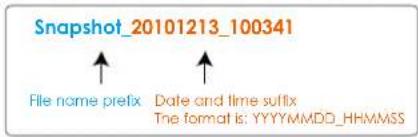
Click Save media to enable the settings.
Note that after you set up the first media server, a new column for media server will automatically display on the Media list. If you wish to add more media options, click Add media.
Media type - Video clip
Select to send video clips when a trigger is activated.
![Media name: Video Clip Media Type Attached media: Snapshot Video Clip Source: Stream 1 Pre-event recording: 0 seconds [0~9] Maximum duration: 5 seconds [1~20] Maximum file size: 500 Kbytes [50~3072] File name prefix: Video Clip_ System log Save media Close](/content/2026/05/1031529/images/d096feb0d70d493ea47a01bb58f3fafcfe94cd5359d67298a5046318de8e7733.jpg)
■ Media name: Enter a name for the media setting.
■ Source: Select a video stream as the source of video clip.
■ Pre-event recording
The Network Camera has a buffer to temporarily hold data up to a certain limit. Enter a number to decide the duration of recording before a trigger is activated. Up to 9 seconds can be set.
■ Maximum duration
Specify the maximum recording duration in seconds. The duration can be up to 10 seconds.
For example, if pre-event recording is set to five seconds and the maximum duration is set to ten seconds, the Network Camera continues to record for another 4 seconds after a trigger is activated.
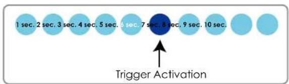
■ Maximum file size
Specify the maximum file size allowed. Some users may need to stitch the video clips together when searching and packing up forensic evidence.
■ File name prefix
Enter the text that will be appended to the front of the file name.
For example:
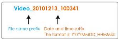
Click Save media to enable the settings.
Media type - System log
Select to send a system log when a trigger is activated.
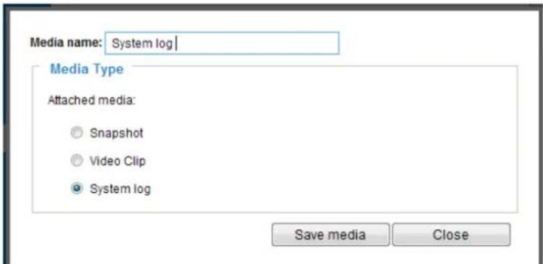
Click Save media to enable the settings, then click Close to exit the page.
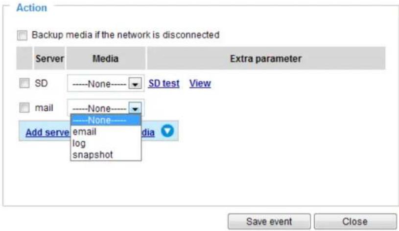
In the Event settings column, the Servers and Medias you configured will be listed; please make sure the Event -> Status is indicated as ON, in order to enable the event triggering action.
When completed, click the Save event button to enable the settings and click Close to exit Event Settings page. The new Event / Server settings / Media will appear in the event drop-down list on the Event setting page.
Please see the example of the Event setting page below:
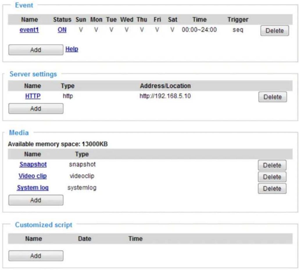
When the Event Status is ON, the event configuration above is triggered by motion detection, the Network Camera will automatically send snapshots via e-mail.
If you want to stop the event trigger, you can click on the ON button to turn it to OFF status or click the Delete button to remove the event setting.
To remove a server setting from the list, select a server name from the drop-down list and click Delete. Note that you can only delete a server setting when it is not applied in an existing setting.
To remove a media setting from the list, select a media name from the drop-down list and click Delete. Note that you can only delete a media setting when it is not applied in an existing setting.
Customized Script
This function allows you to upload a sample script (.xml file) to the webpage, which will save your time on configuring the settings. Please note that there is a limited number of customized scripts you can upload; if the current amount of customized scripts has reached the limit, an alert message will prompt. If you need more information, please contact VIVOTEK technical support.
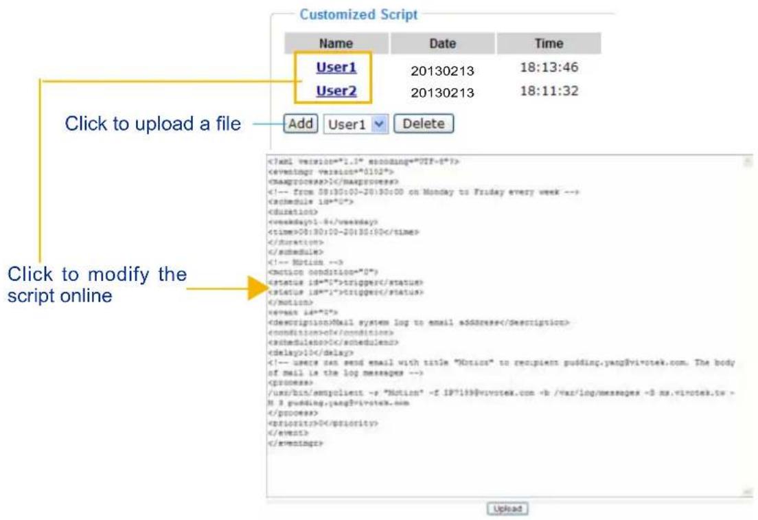
Applications > Motion detection
This section explains how to configure the Network Camera to enable motion detection. A total of three motion detection windows can be configured.
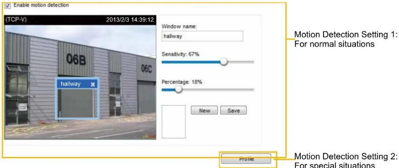
Follow the steps below to enable motion detection:
- Click New to add a new motion detection window.
- In the Window Name text box, enter a name for the motion detection window.
■ To move and resize the window, drag it to a preferred location, and let cursor stay on the edge of the window until it changes into the resize cursor.
■ To delete a window, click X on the upper right corner of the window.
- Define the sensitivity to moving objects and the space ratio of all alerted pixels by moving the Sensitivity and Percentage slider bar.
- Click Save to enable the settings.
- Select Enable motion detection to enable this function.
For example:
√ Enable motion detection
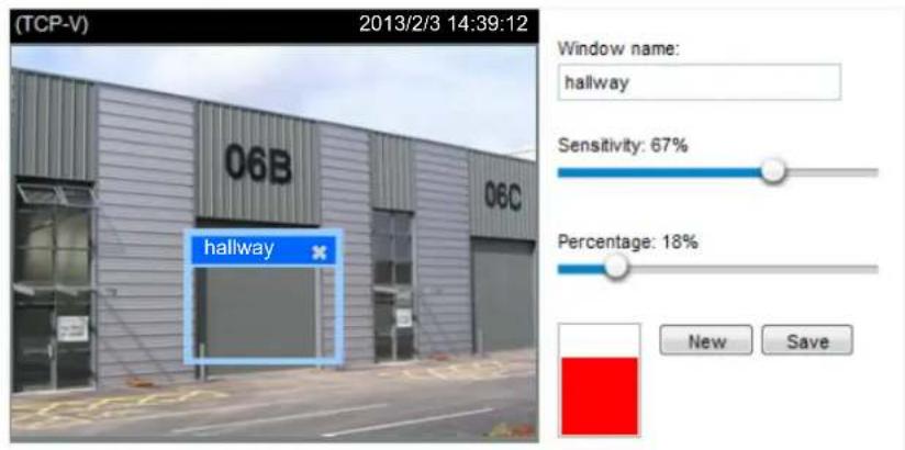
Profile
The Percentage Indicator will rise or fall depending on the variation between sequential images. When motions are detected by the Network Camera and are considered to exceed the preset threshold, the red bar rises. Meanwhile, the motion detection window will be outlined in red for 2 or 3 seconds. Photos or videos can be captured instantly and configured to be sent to a remote server (via an Email or FTP server). For more information on how to configure an event setting, please refer to Event settings on page 81.
A green bar indicates that even though motions have been detected, the event has not been triggered because the image variations still fall under the preset threshold.
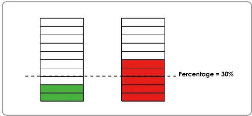
bar_stacked
| Category | Green Segment (%) | Red Segment (%) | |---|---|---| | Row 1 | 25 | 75 | | Row 2 | 25 | 75 | | Row 3 | 25 | 75 | | Row 4 | 25 | 75 | | Row 5 | 25 | 75 | Percentage = 30%If you want to configure other motion detection settings for day/night/schedule mode (e.g., for a different lighting condition), please click on Profile to open the Motion Detection Profile Settings page as shown below. Another three motion detection windows can be configured on this page.
Motion detection profile settings
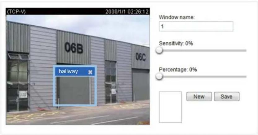
![General settings Enable this profile This profile is applied to: Schedule mode: From 18:00 to 06:00 [hh:mm] Save Close](/content/2026/05/1031529/images/b3d3d8e2394c23992835bedf026aadbb1ada625fc74feedefdc134509e029e48.jpg)
Please follow the steps beolw to set up a profile:
- Create a new motion detection window.
- Check Enable this profile.
- Select the applicable period of time for the Schedule mode. Please manually enter a range of time.
- Click Save to enable the settings and click Close to exit the page.
This motion detection window will also be displayed on the Event Settings page. You can go to Event > Event settings > Trigger to select it as a trigger source. Please refer to page 82 for detailed information.

NOTE:
▶ How does motion detection work?
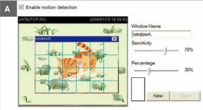
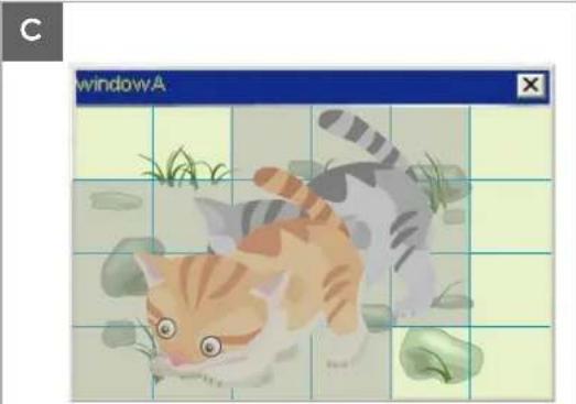
natural_image
Illustration of a cat playing with grass and leaves, displayed within a window titled 'window.A' (no text or symbols on the cat or background)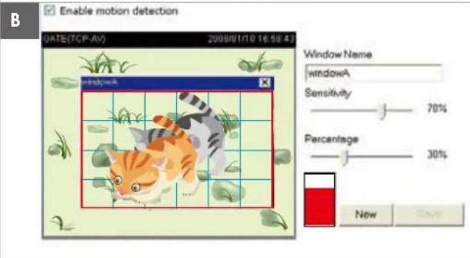
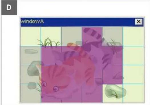
natural_image
Illustration of a fish in a purple and pink patterned frame, with no visible text or symbols.There are two motion detection parameters: Sensitivity and Percentage. In the illustration above, frame A and frame B are two sequential images. Pixel differences between the two frames are detected and highlighted in gray (frame C) and will be compared with the sensitivity setting. Sensitivity is a value that expresses the sensitivity to moving objects. Higher sensitivity settings are expected to detect slight movements while smaller sensitivity settings will neglect them. When the sensitivity is set to 70%, the Network Camera defines the pixels in the purple areas as “alerted pixels” (frame D).
Percentage is a value that expresses the proportion of “alerted pixels” to all pixels in the motion detection window. In this case, 50% of pixels are identified as “alerted pixels”. When the percentage is set to 30%, the motions are judged to exceed the defined threshold; therefore, the motion window will be outlined in red.
For applications that require a high level of security management, it is suggested to use higher sensitivity settings and smaller percentage values.
Applications > Tampering detection
This section explains how to set up camera tamper detection. With tamper detection, the camera is capable of detecting incidents such as redirection, blocking or defocusing, or even spray paint.
![Camera tampering detection Enable camera tampering detection Trigger duration 10 seconds [10~600] Save](/content/2026/05/1031529/images/546a37fea5f3e540593accc361e043a29ffedc27fb6b9147a9573b967345515c.jpg)
Please follow the steps below to set up the camera tamper detection function:
- Check Enable camera tampering detection.
- Enter the tamper trigger duration. (10 sec. \~ 10 min.) The tamper alarm will be triggered only when the tampering factor (the difference between current frame and pre-saved background) exceeds the trigger threshold.
- Set up the event source as Camera Tampering Detection on Event > Event settings > Trigger. Please refer to page 82 for detailed information.
Recording > Recording settings Advanced Mode
This section explains how to configure the recording settings for the Network Camera.
Recording Settings
Recording settings
Name Status Sun Mon Tue Wed Thu Fri Sat Time Source Destination Delete
Add
Note: Before setup recording, you may setup network storage via NAS server page
Recording Settings
Click Add to open the recording setting window. On this page, you can define the adaptive recording, recording source, recording schedule, and recording capacity. A total of 2 recording settings can be configured.
![Recording name: video Enable this recording With adaptive recording Pre-event recording: 5 seconds [0~9] Post-event recording: 5 seconds [0~10] Priority: Normal Source: Stream 1 1. Trigger 2. Destination Trigger Schedule Sun Mon Tue Wed Thu Fri Sat Time Always From 00.00 to 24.00 [hh:mm] Note: To enable recording notification please configure Event first Close Save](/content/2026/05/1031529/images/7236afa376d876a467dde7d5ffd9defd8b74691585b091eea16dc175483f3d31.jpg)
■ Recording name: Enter a name for the recording setting.
■ Enable this recording: Select this option to enable video recording.
■ With adaptive recording:
Select this option will activate the frame rate control according to alarm trigger.
The frame control means that when there is a triggered alarm, the frame rate will raise up to the value you've configured on the Video quality page. Please refer to page 40 for more information.
If you enable adaptive recording on a camera, only when an event is triggered on Camera A will the server record the full frame rate streaming data; otherwise, it will only request the I frame data during normal monitoring, thus effectively saves bandwidths and storage space.
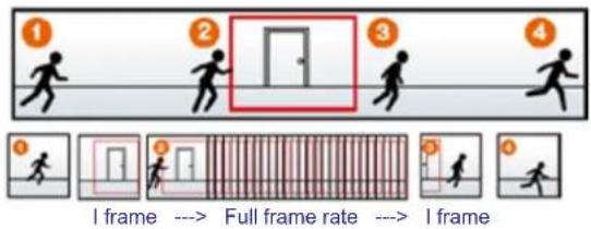
flowchart
graph TD
    A["1: I frame"] --> B["2: Full frame rate"]
    B --> C["3: I frame"]
    C --> D["4: I frame"]
    style A fill:#f9f,stroke:#333
    style B fill:#ccf,stroke:#333
    style C fill:#cfc,stroke:#333
    style D fill:#fcc,stroke:#333
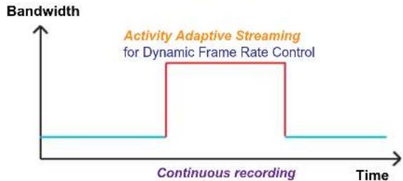
line
| Time | Bandwidth | |------|-----------| | 0 | Low | | 0.5 | High | | 1 | Low | | 1.5 | High | | 2 | Low |
NOTE:
To enable adaptive recording, please make sure you've set up the trigger source such as Motion Detection, DI Device, or Manual Trigger.
▶ When there is no alarm trigger:
- JPEG mode: record 1 frame per second.
- H.264 mode: record the I frame only.
▶ When the I frame period is >1s on Video settings page, firmware will force decrease the I frame period to 1s when adaptive recording is enabled.
The alarm trigger includes: motion detection and DI detection. Please refer to Event Settings on page 81.
■ Pre-event recording and post-event recording
The Network Camera has a buffer that temporarily holds data for a period of time. Therefore, when an event occurs, the camera can retrieve image frames taken several seconds ago. Enter a number to define the duration of recording before and after a trigger is activated.
■ Priority: Select the relative importance of this recording (High, Normal, or Low). Recording with a higher priority setting will be processed first.
■ Source: Select a video stream as the recording source.

NOTE:
▶ To enable recording notification please configure Event settings first. Please refer to page 81.
Please follow the steps below to set up the recording.
1. Trigger
Select a trigger source.
![Trigger Schedule Sun Mon Tue Wed Thu Fri Sat Time Always From 00:00 to 24:00 [hh:mm]](/content/2026/05/1031529/images/2b4298528745ee7f26075e77f9908a206b177e50e5f772e70f6cd113d48f1ab2.jpg)
■ Schedule: The server will start to record files on the local storage or network storage (NAS).
2. Destination
You can select a networked storage (NAS) for the recorded video files. If you have not configured a NAS server, see details in the following.
![Priority: Normal Source: Stream 1 1. Trigger 2. Destination Destination Destination: NAS Capacity: Entire free space Reserved space: 100 Mbytes Enable cyclic recording Recording file management Maximum duration: 1 minutes [1~60] Maximum file size: 100 MB [100~2048] File name prefix: Note: To enable recording notification please configure Event first Save Close](/content/2026/05/1031529/images/8992f4e4347612169b52a149c90a54194ee19a8929fc7585f9d95919fd38d180.jpg)
NAS server
Click Add NAS server to open the server setting window and follow the steps below to set up:
- Fill in the information for your server.
For example:

- Click Test to check the setting. The result will be shown in the pop-up window.
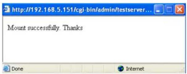
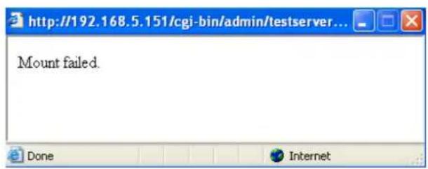
If successful, you will receive a test.txt file on the network storage server.
![NAS on ritali File Edit View Favorites Tools Help Back Search Folders Address \ritali\NAS File and Folder Tasks Rename this file Move this file Copy this file Publish this file to the Web E-mail this file Print this file Delete this file Other Places test.txt Text Document 1 KB test.txt - Notepad File Edit Format View Help [NOTIFICATION]The Result of Server Test of Your IP Camera](/content/2026/05/1031529/images/9643092251399af01abc4c3837f0bea504a1502799e1b564b17ff878a36a3aeb.jpg)
- Enter a server name.
- Click Save to complete the settings and click Close to exit the page.
![Recording name: Enable this recording With adaptive recording (Help) Pre-event recording: 5 seconds [0-10] Post-event recording: 6 seconds [0-10] Priority: Normal Source: Stream 1 Destination Destination: NAS Capacity Entire free space Reserved space: 100 Mbytes Enable cyclic recording Recording file management Maximum duration: 1 minutes [1-30] Maximum file size: 100 MB [50-3072] File name prefix: 1. Trigger 2. Destination Note: To enable recording notification please configure Event first Save Close](/content/2026/05/1031529/images/8df74c53f1ac4388af319d06e3a9032e1acec986f00bf59d928b79e864c4e3d6.jpg)
■ Capacity: You can choose either the entire free space available or limit the reserved space. The recording size limit must be larger than the reserved amount for cyclic recording.
■ Enable cyclic recording: If you check this item, when the maximum capacity is reached, the oldest file will be overwritten by the latest one. The reserved amount is reserved for the transaction stage when the storage space is about to be full and new data arrives. The minimum for the Reserved space must be larger than 15 MegaBytes.
■ Recording file management: You can manually assign the Maximum duration and the Maximum file size for each recording footage. You may need to stitch individual files together under some circumstances. You may also designate a file name prefix by filling in the responsive text field.
■ File name prefix: Enter the text that will be appended to the front of the file name.
f you want to enable recording notification, please click Event to configure event triggering settings. Please refer to Event > Event settings on page 81 for more details.
When completed, select Enable this recording. Click Save to enable the setting and click Close to exit this page. When the system begins recording, it will send the recorded files to the network storage. The new recording name will appear in the drop-down list on the recording page as shown below.
To remove a recording setting from the list, select a recording name from the drop-down list and click Delete.
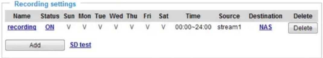
- Click recording (Name): Opens the Recording Settings page to modify.
■ Click ON (Status): The Status will become OFF and stop recording.
■ Click NAS (Destination): Opens the file list of recordings as shown below. For more information about folder naming rules, please refer to page 87 for details.
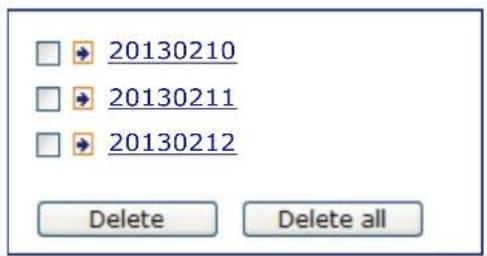
Appendix
URL Commands for the Network Camera/Video Server
1. Overview
For some customers who already have their own web site or web control application, the Network Camera/Video Server can be easily integrated through URL syntax. This section specifies the external HTTP-based application programming interface. The HTTP-based camera interface provides the functionality to request a single image, control camera functions (PTZ, output relay etc.), and get and set internal parameter values. The image and CGI-requests are handled by the built-in Web server.
2. Style Convention
In URL syntax and in descriptions of CGI parameters, text within angle brackets denotes content that is to be replaced with either a value or a string. When replacing the text string, the angle brackets should also be replaced. An example of this is the description of the name for the server, denoted with
URL syntax is denoted with the word "Syntax:" written in bold face followed by a box with the referenced syntax as shown below. For example, name of the server is written as
Syntax:
http://
Description of returned data is written with "Return:" in bold face followed by the returned data in a box. All data is returned in HTTP format, i.e., each line is separated with a Carriage Return and Line Feed (CRLF) printed as \r\n.
Return:
HTTP/1.0
URL syntax examples are written with "Example:" in bold face followed by a short description and a light grey box with the example.
Example: request a single snapshot image
http://mywebserver/cgi-bin/viewer/video.jpg
3. General CGI URL Syntax and Parameters
When the CGI request includes internal camera parameters, these parameters must be written exactly as they are named in the camera or video server. The CGIs are organized in functionally-related directories under the cgi-bin directory. The file extension .cgi is required.
Syntax:
http://<servername>/cgi-bin/<subdir>[/<subdir>...]/<cgi>.<ext>
[?<parameter><value>[&<parameter><value>...]]
Example: Set digital output #1 to active
http://mywebserver/cgi-bin/dido/setdo.cgi?do1=1
4. Security Level
| SECURITY LEVEL | SUB-DIRECTORY DESCRIPTION | |
| 0 anonymous | Unprotected. | |
| 1 [view] anonymous, viewer, dido, camctrl | 1. Can view, listen, talk to camera.2. Can control DI/DO, PTZ of the camera. | |
| 4 [operator] anonymous, viewer, dido, camctrl, operator | Operator access rights can modify most of the camera's parameters except some privileges and network options. | |
| 6 [admin] anonymous, viewer, dido, camctrl, operator, admin | Administrator access rights can fully control the camera's operations. | |
| 7 N/A Internal parameters. Unable to be changed by any external interfaces. | ||
5. Get Server Parameter Values
Note: The access right depends on the URL directory.
Method: GET/POST
Syntax:
http://<servername>/cgi-bin/anonymous/getparam.cgi?[<parameter>]
[&<parameter>...]

http://<servername>/cgi-bin/viewer/getparam.cgi?[<parameter>]
[&<parameter>...]

http://<servername>/cgi-bin/operator/getparam.cgi?[<parameter>]
[&<parameter>...]

http://<servername>/cgi-bin/admin/getparam.cgi?[<parameter>]
[&<parameter>...]
Where the
When querying parameter values, the current parameter values are returned.
A successful control request returns parameter pairs as follows:
Return:
HTTP/1.0 200 OK\r\n
Content-Type: text/html\r\n
Context-Length: <length>\r\n
\r\n
<parameter pair>
where
[
Example: Request IP address and its response
Request:
http://192.168.0.123/cgi-bin/admin/getparam.cgi?network_ipaddress
Response:
HTTP/1.0 200 OK\r\n
Content-Type: text/html\r\n
Context-Length: 33\r\n
\r\n
network_ipaddress=192.168.0.123\r\n
6. Set Server Parameter Values
Note: The access right depends on the URL directory.
Method: GET/POST
Syntax:
http://<servername>/cgi-bin/anonymous/setparam.cgi? <parameter>=<value>
[&<parameter>=<value>...][&return=<return page]

http://<servername>/cgi-bin/viewer/setparam.cgi? <parameter>=<value>
[&<parameter>=<value>...][&return=<return page]

http://<servername>/cgi-bin/operator/setparam.cgi? <parameter>=<value>
[&<parameter>=<value>...][&return=<return page]

http://<servername>/cgi-bin/admin/setparam.cgi? <parameter>=<value>
[&<parameter>=<value>...][&return=<return page]
| PARAMETER VALUE DESCRIPTION | ||
| value to assigned | Assignto the parameter. | |
| return | Redirect to the pageafter the parameter is assigned. Thecan be a full URL path or relative path according to the current path. If you omit this parameter, it will redirect to an empty page.(Note: The return page can be a general HTML file (.htm, .html). It cannot be a CGI command or have any extra parameters. This parameter must be placed at the end of the parameter list | |
Return:
HTTP/1.0 200 OK\r\n
Content-Type: text/html\r\n
Context-Length: <length>\r\n
\r\n
<parameter pair>
where <parameter pair> is
<parameter>=<value>\r\n
[<parameter pair>]
Only the parameters that you set and are readable will be returned.
Example: Set the IP address of server to 192.168.0.123:
Request:
http://myserver/cgi-bin/admin/setparam.cgi?network_ipaddress=192.168.0.123
Response:
HTTP/1.0 200 OK\r\n
Content-Type: text/html\r\n
Context-Length: 33\r\n
\r\n
network_ipaddress=192.168.0.123\r\n
7. Available parameters on the server
This chapter defines all the parameters which can be configured or retrieved from VIVOTEK network camera or video server. The general format of description is listed in the table below
Valid values:
| VALID VALUES DESCRIPTION | |
| string[] | Text strings shorter than ‘n’ characters. The characters ‘,’, <,>,& are invalid. |
| string[n~m] | Text strings longer than ‘n’ characters and shorter than ‘m’ characters. The characters ‘,’, <,>,& are invalid. |
| password[] The same as string but displays ‘*’ instead. | |
| integer Any number between (-2 ^31 – 1) and ( 2^31 – 1). | |
| positive integer Any number between 0 and (2 ^32 – 1). | |
| ~Any number between ‘m’ and ‘n’. | |
| domain name[] A string limited to a domain name shorter than ‘n’ characters (eg. www.ibm.com). | |
| email address [] | A string limited to an email address shorter than ‘n’ characters (eg. joe@www.ibm.com). |
| ip address A string limited to an IP address (eg. 192.168.1.1). | |
| mac address A string limited to contain a MAC address without hyphens or colons. | |
| boolean A boolean value of 1 or 0 represents [Yes or No], [True or False], [Enable or Disable]. | |
| ,,,,,,... | Enumeration. Only given values are valid. |
| blank | A blank string. |
| everything inside <> | A description |
| integer primary key | SQLite data type. A 32-bit signed integer. The value is assigned a unique integer by the server. |
| text | SQLite data type. The value is a text string, stored using the database encoding (UTF-8, UTF-16BE or UTF-16-LE). |
| coordinate | x, y coordinate (eg. 0,0) |
| window size | window width and height (eg. 800x600) |
NOTE: The camera should not be restarted when parameters are changed.
7.1 system
Group: system
| NAME VALUE DEFAULT | SECURITY | (get/set) | DESCRIPTION | |
| hostname string[64] | Video Server | 1/6 Host name | of server(Network Camera, Wireless Network Camera, Video Server, Wireless Video Server). | |
| lcdoff0 6/6 Turn on (0) or turn off(1) all | led indicators. | |||
| date, keep, auto | , | 6/6 Current date of system. Set to ‘keep’ to keep date unchanged. Set to ‘auto’ to use NTP to synchronize date. | ||
| time, keep, auto | , keep, auto | 6/6 Current time of the system.Set to ‘keep’ to keep time unchanged. Set to ‘auto’ to use NTP to synchronize time. | ||
| datetime | YYYY.ss> | 6/6 Another current time format of the system. | ||
| ntp,,, | 6/6 NTP server. | *Do not use “skip to invoke default server” for default value. | ||
| timezoneindex | -489 ~ 529 | 320 | 6/6 | Indicate timezone and area.-480: GMT-12:00 Eniwetok, Kwajalein-440: GMT-11:00 Midway Island, Samoa-400: GMT-10:00 Hawaii-360: GMT-09:00 Alaska-320: GMT-08:00 Las Vegas, San_Francisco, Vancouver-280: GMT-07:00 Mountain Time, Denver-281: GMT-07:00 Arizona-240: GMT-06:00 Central America, Central Time,Mexico City, Saskatchewan-200: GMT-05:00 Eastern Time, New York, Toronto-201: GMT-05:00 Bogota,Lima, Quito, Indiana-180: GMT-04:30 Caracas-160: GMT-04:00 Atlantic Time, Canada, La Paz,Santiago-140: GMT-03:30 Newfoundland-120: GMT-03:00 Brasilia,Buenos Aires,Georgetown, Greenland-80: GMT-02:00 Mid-Atlantic-40: GMT-01:00 Azores,Cape_Verde_IS.0: GMT Casablanca,Greenwich Mean Time:Dublin,Edinburgh, Lisbon, London40: GMT 01:00 Amsterdam,Berlin, Rome, Stockholm,Vienna, Madrid, Paris41: GMT 01:00 Warsaw,Budapest, Bern80: GMT 02:00 Athens,Helsinki, Istanbul, Riga81: GMT 02:00 Cairo82: GMT 02:00 Lebanon,Minsk83: GMT 02:00 Israel120: GMT 03:00 Baghdad,Kuwait, Riyadh, Moscow, St.Petersburg, Nairobi121: GMT 03:00 Iraq140: GMT 03:30 Tehran160: GMT 04:00 Abu Dhabi, Muscat, Baku,Tbilisi, Yerevan180: GMT 04:30 Kabul200: GMT 05:00Ekaterinburg, Islamabad,Karachi, Tashkent220: GMT 05:30 Calcutta,Chennai, Mumbai, New Delhi230: GMT 05:45 Kathmandu240: GMT 06:00 Almaty,Novosibirsk, Astana, Dhaka,Sri Jayawardenepura260: GMT 06:30 Rangoon280: GMT 07:00 Bangkok,Hanoi, Jakarta, Krasnoyarsk320: GMT 08:00 Beijing,Chongging, Hong Kong,Kuala Lumpur, Singapore,Taipei360: GMT 09:00 Osaka,Sapporo, Tokyo, Seoul,Yakutsk380: GMT 09:30 Adelaide,Darwin400: GMT 10:00 Brisbane,Canberra, Melbourne,Sydney, Guam, Vladivostok440: GMT 11:00 Magadan,Solomon Is., New Caledonia480: GMT 12:00 Auckland,Wellington, Fiji, Kamchatka,Marshall Is.520: GMT 13:00 Nuku'Alofa |
| daylight_enable | 0 6/6 Enable automatic daylight | saving time in time zone. | ||
| daylight_auto_begintime string[19] NONE 6/7 Display the current daylight | saving start time. | |||
| daylight_auto_endtime string[19] NONE 6/7 Display the current daylight | saving end time. | |||
| daylight_timezones | string | ,-3606-320List time zone index which support daylight saving time. | |
| -280,-240,-241,-200,-201,-160,-140,-120,-80,-40,0,40,41,80,81,82,83,120,140,380,400,480 | |||
| updateinterval | 0,3600,86400,604800,2592000 | 0 6/6 0 to D | isable automatic time adjustment, otherwise, it indicates the seconds between NTP automatic update intervals. |
| restore | 0,<positive integer> | N/A 7/6 Restore the system | parameters to default values afterseconds. |
| reset | 0,<positive integer> | N/A 7/6 Restart the server afterseconds ifis non-negative. | |
| restoreexceptnet <Any value> | N/A 7/6 Restore the system | ||
| restoreexceptdst <Any value> | N/A 7/6 Restore the system | ||
| with other“restoreexceptXYZ” commands. When cooperating with others, the system parameters will be restored to default values except for a union of combined results. | ||||
| restoreexceptlangN/A 7/6 Restore the systemparameters to default values except the custom language file the user has uploaded. This command can cooperate with other “restoreexceptXYZ” commands. When cooperating with others, the system parameters will be restored to the default value except for a union of the combined results. | ||||
7.1.1 system.info
Subgroup of system: info (The fields in this group are unchangeable.)
| NAME VALUE DEFAULT | SECURITY | (get/set) | DESCRIPTION | |
| modelname string[40] VS8100 0/7 Internal model name of the server (eg, IP7139) | ||||
| extendedmodelname string[40] VS8100 0/7 ODM specific model name of server (eg. DCS-5610). If it is not an ODM model, this field will be equal to “modelname” | ||||
| serialnumber | 0/7 12 characters MAC address (without hyphens). | |||
| firmwareversion | string[40] | 0/7 Firmware version, including model, company, and version number in the format: | ||
| language_count | 9 | 0/7 | Number of webpage languages available on the server. | |
| language_i<0~(count-1)> | string[16] | 0/7 Available language lists. | ||
| customlanguage_maxcount | 1 0/6 Maximum number of custom languages supported on the server. | |||
| customlanguage_count | 0 0/6 Number of custom languages | which have been uploaded to the server. | ||
| customlanguage_i<0~(max count-1)> | string N/A | 0/6 Custom language name. | ||
7.2 status
Group: status
| NAME | VALUE | DEFAULT | SECURITY (get/set) | DESCRIPTION |
| onlinenum_rtsp | integer | 0 | 6/7 | Current number of RTSP connections. |
| onlinenum_htppush | integer | 0 | 6/7 | Current number of HTTP push server connections. |
| eth_i0 | 1/7 | Get network information from mii-tool. | ||
| vi_i<0~(nvi-1)> | 0 | 1/7 | Virtual input0 => Inactive1 => Active(capability.nvi > 0) | |
| signal_c<0~(nvideoin-1)> | 0 | 1/7 | 0=> No signal.1=> Signal detected. | |
| videomode_c<0~(nvideoin-1)> | ntsc,pal | ntsc 1/7 | Video modulation type | |
7.3 security
Group: security
| NAME | VALUE | DEFAULT | SECURITY (get/set) | DESCRIPTION |
| privilege_camctrladmin above can control PTZ | view, operator, | view | 1/6 | Indicate which privileges and(capability.ptzenabled > 0 or capability.cptz > 0) |
| user_i0_name string[64] root 6/7 User name of root | ||||
| user_i<1~20>_name string[64] <blank> 6/7 User name | ||||
| user_i0_pass password[64] <blank> 6/6 Root password | ||||
| user_i<1~20>_pass password[64] <blank> 7/6 User password | ||||
| user_i0_privilege admin admin 6/7 Root privilege | ||||
| user_i<1~20>_privilege | view,operator,admin | <blank> 6/6 | User privilege | |
7.4 network
Group: network
| NAME | VALUE | DEFAULT | SECURITY (get/set) | DESCRIPTION |
| preprocess | NULL | 6/6 An 32-bit | integer, each bit can be set separately as follows:Bit 0 => HTTP service;Bit 1=> HTTPS service;Bit 2=> FTP service;Bit 3 => Two way audio and RTSP Streaming service;To stop service before changing its port settings.It'srecommendedto set this parameter when change a service port to the port occupied by another service currently. Otherwise, the service may fail.Stopped service will auto-start after changing port settings.Ex:Change HTTP port from 80 to 5556, and change RTP port for video from 5556 to 20480.Then, set preprocess=9 to stop both service first.”/cgi-bin/admin/setparam.cgi?network_preprocess=9&network_http_port=5556 & network_rtp_videoport=20480” | |
| type lan, | lan 6/6pppoe | Network connection type. | ||
| resetip1 6/6 => Get ipaddress, subnet, router, dns1, dns2from DHCP server at next reboot.0 => Use preset ipaddress, subnet, rounter, dns1,and dns2. | 1 => Get ipaddress, subnet, router, dns1, dns2from DHCP server at next reboot.0 => Use preset ipaddress, subnet, rounter, dns1,and dns2. | |||
| ipaddress | 6/6 IP address | of server. | ||
| subnet | 6/6 | Subnet mask. | ||
| router | 6/6 | Default gateway. | ||
| dns1 | 6/6 | Primary DNS server. | ||
| dns2 | 6/6 | Secondary DNS server. | ||
| wins1 | 6/6 | Primary WINS server. | ||
| wins2 | 6/6 | Secondary WINS server. | ||
7.4.1 802.1x
Subgroup of network: ieee8021x (capability.protocol.ieee8021x > 0)
| NAME VALUE DEF | AULT SECURITY | (get/set) | DESCRIPTION | |
| enable0 | 6/6 Enable/disable IEEE 802.1x | |||
| eapmethod | eap-peap, cap-tls | eap-peap | 6/6 Selected EAP method | |
| identity_peap | String[64] | 6/6 | PEAP identity | |
| identity_tls | String[64] | 6/6 | TLS identity | |
| password | String[254] | 6/6 | Password for TLS | |
| privatekeypassword | String[254] | 6/6 | Password for PEAP | |
| ca_exist | 0 | 6/6 CA installed flag | ||
| ca_time | 0 | 6/7 CA installed time. Represented in EPOCH | ||
| ca_size0 | 6/7 CA file size (in bytes) | |||
| certificate_exist | 0 | 6/6 | Certificate installed flag (for TLS) | |
| certificate_time0 6/7 Certificate installed time. | Represented in EPOCH | ||
| certificate_size0 6/7 Certificate file size (in bytes) | |||
| privatekey_exist0 6/6 Private key installed flag (for TLS) | |||
| privatekey_time0 6/7 Private key installed time. | Represented in EPOCH | ||
| privatekey_size0 6/7 Private key file size (in bytes) | |||
7.4.2 QOS
Subgroup of network: qos_cos (capability.protocol.qos.cos > 0)
| NAME VALUE | DEFAULT SECURITY | (get/set) | DESCRIPTION | |
| enable | <boolean> 0 | 6/6 | Enable/disable CoS (IEEE 802.1p) | |
| vlanid | 1~4095 | 1 | 6/6 VLAN ID | |
| video | 0~7 | 0 | 6/6 | Video channel for CoS |
| audio | 0~7 | 0 | 6/6 | Audio channel for CoS(capability.naudio >0) |
| eventalarm | 0~7 | 0 | 6/6 | Event/alarm channel for CoS |
| management | 0~7 | 0 | 6/6 | Management channel for CoS |
| eventtunnel | 0~7 | 0 | 6/6 | Event/Control channel for CoS |
Subgroup of network: qos_dscp (capability.protocol.qos.dscp > 0)
| NAME VALUE | DEFAULT SECURITY | (get/set) | DESCRIPTION | |
| enable | <boolean> 0 | 6/6 | Enable/disable DSCP | DSCP |
| video | 0~63 | 0 | 6/6 | Video channel for DSCP |
| audio | 0~63 | 0 | 6/6 | Audio channel for DSCP(capability.naudio >0) |
| eventalarm | 0~63 | 0 | 6/6 | Event/alarm channel for DSCP |
| management | 0~63 | 0 | 6/6 | Management channel for DSCP |
| eventtunnel | 0~63 | 0 | 6/6 | Event/Control channel for DSCP |
7.4.3 IPV6
Subgroup of network: ipv6 (capability.protocol.ipv6 > 0)
| NAME VALUE DEF | AULT SECURITY | (get/set) | DESCRIPTION | ||
| enable0 6/6 Enable IPv6. | |||||
| addonipaddress6/6IPv6 IP address. | IPv6 IP address. | ||||
| addonprefixlen 0~128 64 6/6 IPv6 prefix length. | |||||
| addonrouter | |||||
| addondns | |||||
| allowoptional0 6/6 Allow manually setup of IP | address setting. | ||||
7.4.4 FTP
Subgroup of network: ftp
| NAME VALUE DEF | AULT SECURITY | (get/set) | DESCRIPTION | |
| port | 21, 1025~65535 | 21 6/6 Local | ftp server port. |
7.4.5 HTTP
Subgroup of network: http
| NAME | VALUE | DEFAULT | SECURITY (get/set) | DESCRIPTION |
| port | 80, 1025 ~ 65535 | 80 | 1/6 HTTP port. | |
| alternateport | 1025~65535 | 8080 6/6 Alternate HTTP port. | ||
| authmode | basic,digest | basic 1/6 HTTP | authentication mode. | |
| s0_accessname | string[32] | video.mjpg | 1/6 | HTTP server push access name for stream 1.(capability.protocol.spush_mjpeg=1 and capability.nmediastream >0) |
| s1_accessname | string[32] | video2.mjpg | 1/6 | HTTP server push access name for stream 2.(capability.protocol.spush_mjpeg=1 and capability.nmediastream > 1) |
| s2_accessname string[32] video3.mjpg 1/6 Http server push access name for stream 3(capability.protocol.spush_mjpeg =1 and capability.nmediastream > 2) | 1/6 | push access name for stream 3(capability.protocol.spush_mjpeg =1 and capability.nmediastream > 2) | ||
| anonymousviewing | 0 | 1/6 | Enable anonymous streaming viewing. | |
7.4.6 HTTPS port
Subgroup of network: https_port (capability.protocol.https > 0)
| NAME VALUE DEFAULT SECURITY | (get/set) | DESCRIPTION | |
| port | 443, 1025 ~ 65535 | 443 | 1/6 HTTPS port. |
7.4.7 RTSP
Subgroup of network: rtsp (capability.protocol.rtsp > 0)
| NAME | VALUE | DEFAULT | SECURITY (get/set) | DESCRIPTION |
| port | 554, 1025 ~ 65535 | 554 | 1/6 | RTSP port. (capability.protocol.rtsp=1) |
| anonymousviewing | 0 | 1/6 | Enable anonymous streaming viewing. | |
| authmode | disable, basic, digest | disable | 1/6 | RTSP authentication mode. (capability.protocol.rtsp=1) |
| s0_accessname | string[32] | live.sdp | 1/6 | RTSP access name for stream1. (capability.protocol.rtsp=1 and capability.nmediastream >0) |
| s1_accessname | string[32] | live2.sdp | 1/6 | RTSP access name for stream2. (capability.protocol.rtsp=1 and capability.nmediastream >1) |
| s2_accessname | string[32] | live3.sdp | 1/6 | RTSP access name for stream3 (capability.protocol.rtsp=1 and capability.nmediastream >2) |
7.4.7.1 RTSP multicast
Subgroup of network_rtsp_s<0\~(n-1)>: multicast, n is stream count
(capability.protocol.rtp.multicast > 0)
| NAME VALUE | DEFAULT SECURITY | (get/set) | DESCRIPTION |
| alwaysmulticast <boolean> 0 4/4 Enable always multicast. | |||
| ipaddress <ip address> For n=0, | For n=0,239.128.1.99For n=1,239.128.1.100,and so on. | 4/4 Multicast | IP address. |
| videoport 1025 ~ 6 | 5535 5560+n*2 4/4 | Multicast video port. | |
| audiport 1025 ~ 6 | 5535 5562+n*2 4/4 | Multicast audio port. | (capability.naudio >0) |
| ttl | 1 ~ 255 | 15 | 4/4 Multicast time to live value. |
7.4.8 RTP port
Subgroup of network: rtp
| NAME | VALUE | DEFAULT | SECURITY (get/set) | DESCRIPTION |
| videoport | 1025 ~ 65535 | 5556 | 6/6 | Video channel port for RTP. (capability.protocol.rtp_unicast=1) |
| audiport | 1025 ~ 65535 | 5558 | 6/6 | Audio channel port for RTP. (capability.protocol.rtp_unicast=1) |
7.4.9 PPPoE
Subgroup of network: pppoe (capability.protocol.pppoe > 0)
| NAME | VALUE | DEFAULT | SECURITY (get/set) | DESCRIPTION |
| user | string[128] | 6/6 | PPPoE account user name. | |
| pass | password[64] | 6/6 | PPPoE account password. |
7.5 IP Filter
Group: ipfilter
| NAME VALUE DEFAULT SECURITY | (get/set) | DESCRIPTION | ||
| enable0 | 6/6 Enable access list filtering. | |||
| admin_enable0 6/6 Enable administrator IP | address. | |||
| admin_ip String[44] | 6/6 Administrator IP address. | |||
| maxconnection | 0~10 | 10 | 6/6 | Maximum number of concurrent streaming connection(s). |
| type | 0, 1 | 1 | 6/6 | Ipfilter policy :0 => allow1 => deny |
| ipv4list_i<0~9> | Single address:Networkaddress:Rangeaddress: | 6/6 | IPv4 address list. | |
| ipv6list_i<0~9> | String[44] | 6/6 | IPv6 address list. | |
7.6 video input
Group: videoin
| NAME | VALUE | DEFAULT | SECURITY (get/set) | DESCRIPTION |
| color | 0, 1 | 1 | 4/4 0 =>mono | chrome1 => color |
| flip | 0 | 4/4 | Flip the image. | |
| mirror | 0 | 4/4 | Mirror the image. | |
| ptzstatus | 2 | 1/7 | A 32-bit integer, each bit can be set separately as follows:Bit 0 => Support camera control function; 0(not support),1(support)Bit 1 => Built-in or external camera; 0 (external), 1(built-in)Bit 2 => Support pan operation;0(not support), 1(support)Bit 3 => Support tilt operation;0(not support), 1(support)Bit 4 => Support zoom operation;0(not support), 1(support)Bit 5 => Support focus operation;0(not support), 1(support) | |
| text string[60] <blank> | 1/4 Enclose caption. | |||
| imprinttimestamp <boolean> | 0 4/4 Overlay time stamp on video. | |||
7.6.1 video input setting per channel
Group: videoin_c<0\~(n-1)> for n channel products, and m is stream number
| NAME VALUE DEFAULT | SECURITY | (get/set) | DESCRIPTION | |
| color 0, 1 1 4/4 | 0 => monochrome | 1 => color | ||
| flip | 0 | 4/4 | Flip the image. | |
| mirror | 0 | 4/4 | Mirror the image. | |
| ptzstatus | 2 | 1/7 | A 32-bit integer, each bit can be set separately as follows:Bit 0 => Support camera control function; 0 (not support), 1 (support)Bit 1 =>Built-in or external camera; 0 (external), 1 (built-in)Bit 2 => Support pan operation; 0 (not support), 1 (support)Bit 3 => Support tilt operation; 0 (not support), 1 (support)Bit 4 => Support zoomoperation; 0(not support),1(support)Bit 5 => Support focus operation; 0(not support),1(support) | |
| text string[60]1/4 Enclose caption. | ||||
| imprinttimestamp0 4/4 Overlay time stamp on | video. | |||
| s<0~(m-1>_codectype mjpeg, h264 h264 1/4 Video codec type. | svc is only supported with stream 0. | |||
| s<0~(m-1>_resolution QCIF,CIF,4CIF,D1 | D1 1/4 Video resolution in pixels. | |||
| s<0~(m-1>_ratiocorrect0 1/4 Change resolution to fit 4:3 | ratio.For PAL:D1/4CIF(720/704x576) -> (768x576)CIF(352x288)->(384x288)For NTSC:D1/4CIF(720/704x480) -> (640x480)CIF(352x240)->(320x240) | |||
| s<0~(m-1>_h264_intraperiod | 250, 500, 1000, 2000, 3000, 4000 | 1000 4/4 Intra frame period | in milliseconds. | |
| s<0~(m-1>_h264_prioritypolicy | framerate,imagequality | framerate 4/4 The policy to | apply when the target bit rate is not sufficient to satisfy current encoded conditions.“framerate” indicates frame rate first.“imagequality” indicates image quality first. | |
| s<0~(m-1>_h264_ratecontrolmode | cbr, vbr | cbr | 4/4 cbr, constant bitratevbr, fix quality | |
| s<0~(m-1)>_h264_quant 1~5,9 | 99,100 3 4/4 Quality of video when | choosing vbr in“ratecontrolmode”.Set the pre-defined quality level:1: Median2: Standard3: Good4: Detailed5: Excellent100: Use the quality level in"qpercent"99: Use the quality level in"qvalue" | ||
| s<0~(m-1)>_h264_qpercent 1~100 50 4/4 Set quality by percentage. | 1: Worst quality100: Best quality(s<0~(m-1)>_h264_quant =100) | |||
| s<0~(m-1)>_h264_qvalue 0~51 29 4/4 Manual video quality level | input.(s<0~(m-1)>_h264_quant =99) | |||
| s<0~(m-1)>_h264_bitrate 1000~40000000 | 3000000 4/4 | Set bit rate in bps when choosing cbr in“ratecontrolmode”. | ||
| s<0~(m-1)>_h264_maxframe 1~25,26~30 (only for NTSC or 60Hz CMOS) | 25 => PALCCD or50HzCMOS30 =>NTSCCCD or60HzCMOS | 1/4 Set maximum frame rate infps (for h264). | ||
| s<0~(m-1)>_h264_profile | 0~2 | 1 | 1/4 | Indicate H264 profiles0: baseline1: main profile2: high profile |
| s<0~(m-1)>_mjpeg_prioritypolicy imagequality the target bit rate is not | framerate, | framerate | 4/4 | The policy to apply whensufficient to satisfy current encoded conditions. “framerate” indicates frame rate first. “imagequality” indicates image quality first. |
| s<0~(m-1)>_mjpeg_ratecontrolmode | cbr, vbr vbr 4/4 | cbr, constant | bitrate | vbr, fix quality |
| s<0~(m-1)>_mjpeg_quant | 1~5,99,100 | 3 4/4 | Quality of JPEG | video. Set the pre-defined quality level: 1: Median 2: Standard 3: Good 4: Detailed 5: Excellent 100: Use the quality level in "qpercent" 99: Use the quality level in "qvalue" |
| s<0~(m-1)>_mjpeg_maxframe | 1~25, 26~30 (only for NTSC or 60Hz CMOS) | 25 => PAL CCD or 50Hz CMOS 30 => NTSC CCD or 60Hz CMOS | 1/4 Set maximum frame rate in fps (for JPEG). | |
| s<0~(m-1)>_mjpeg_qvalue | 10~200 | 49 4/4 Manual video quality | level input. (s<0~(m-1)>_mjpeg_quant = 0) | |
| s<0~(m-1)>_mjpeg_qpercent | 1~100 50 | 4/4 Set quality | by percentage. | 1: Worst quality 100: Best quality (s<0~(m-1)>_mjpeg_quant = 100) |
| s<0~(m-1)>_mjpeg_bitrate | 1000~8000000 | 6000000 4/4 | Set bit rate in | bps when choosing cbr in “ratecontrolmode”. |
| s<0~(m-1)>_forcei 1 N/A 7/6 | Force I frame. | |||
7.7 image setting per channel
Group: image_c<0\~(n-1)> for n channel products
| NAME VALUE DEFAULT SECURITY | (get/set) | DESCRIPTION | ||
| brightness | -5 ~ 5,100 | 100 | 4/4 | Adjust brightness of image according to mode settings. |
| saturation | -5 ~ 5,100 | 100 | 4/4 | Adjust saturation of image according to mode settings. |
| contrast | -5 ~ 5,100 | 100 | 4/4 | Adjust contrast of image according to mode settings. |
| sharpness | -3 ~ 3,100 | 100 | 4/4 | Adjust sharpness of image according to mode settings. |
| brightnesspercent | 0 ~ 100 | 50 | 4/4 | Adjust brightness of image by percentage.Darker 0 <-> 100 Brighter |
| saturationpercent | 0 ~ 100 | 50 | 4/4 | Adjust saturation of image by percentage.Less 0 <-> 100 More saturation |
| contrastpercent | 0 ~ 100 | 50 | 4/4 | Adjust contrast of image by percentage.Less 0 <-> 100 More contrast |
| sharpnesspercent | 0~100 | 50 | 4/4 | Adjust sharpness of image by percentage.Softer 0 <-> 100 Sharper |
| IBPE_nrenable | 0 | 4/4 | Enable noise reduction. | |
| IBPE_nrstrength | 0 ~ 100 | 5 | 4/4 | Adjust noise reduction strength. 0 is minimum and 100 is maximum. |
| xoffset | 0 ~ 100 | 13 | 4/4 | Change start point of input image in horizontal. |
| deinterlace_enable | 1 | 4/4 | Enable de-interlace. This is enabled by default. | |
| deinterlace_mode | adaptive, | adaptive | 4/4 | Adaptive: Detect moving area and |
| blend perform de-interlace on it. This | mode leads to better image quality, but consumes more resource. Blend: Use blend method to perform de-interlace. | |||
7.8 Audio input per channel
Group: audioin_c<0\~(n-1)> for n channel products (capability.audioin>0)
| NAME VALUE DEFAULT | SECURITY | (get/set) | DESCRIPTION | |
| source | linein | linein 4/4 linein => use external microphone input. | ||
| mute 0,1 1 | 1/4 Enable audio mute. | 0 => Audio is enabled1 => Audio is muted | ||
| gain | 0~100 | 65 | 4/4 Gain of input.(audioin_c<0~(n-1)>_source = linein) | |
| s<0~(m-1>_codectype | g711, g726 | g711 | 4/4 | Set audio codec type for input. |
| s<0~(m-1>_g711_mode | pcmu, pcma | pcmu | 4/4 Set G.711 | mode. |
| s<0~(m-1>_g726_bitrate | 16000, 24000, 32000, 40000 | 32000 | 4/4 Set G.726 | bitrate in bps. |
7.9 Time Shift settings
Group: timeshift, c for n channel products, m is stream number (capability.timeshift > 0)
| NAME VALUE DEFAULT | T | SECURITY(get/set) | DESCRIPTION | |
| enable0 | 4/4 Enable time shift | streaming. | ||
| c<0~(n-1)>_s<0~(m-1)>_allow | 0 4/4 Enable time shift streaming for specific stream. | |||
7.10 Motion detection settings
Group: motion_c<0\~(n-1)> for n channel product
| NAME VALUE DEFAULT SECURITY | (get/set) | DESCRIPTION | ||
| enable0 4/4 | Enable motion | detection. | ||
| win_i<0~2>_enable | 0 | 4/4 Enable motion window 1~3. | ||
| win_i<0~2>_name | string[40] | 4/4 | Name of motion window 1~3. | |
| win_i<0~2>_left | 0 ~ 320 | 0 4/4 Left coordinate of window position. | ||
| win_i<0~2>_top | 0 ~ 240 | 0 4/4 Top coordinate of window position. | ||
| win_i<0~2>_width | 0 ~ 320 | 0 | 4/4 | Width of motion detection window. |
| win_i<0~2>_height | 0 ~ 240 | 0 | 4/4 | Height of motion detection window. |
| win_i<0~2>_objsize | 0 ~ 100 | 0 | 4/4 | Percent of motion detection window. |
| win_i<0~2>_sensitivity | 0 ~ 100 | 0 | 4/4 | Sensitivity of motion detection window. |
Group: motion_c<0\~(n-1)>_profile for m profile and n channel product (capability.nmotionprofile > 0)
| NAME | VALUE | DEFAULT | SECURITY (get/set) | DESCRIPTION |
| i<0~(m-1)>_enable | 0 | 4/4 | Enable profile 1 ~ (m-1). | |
| i<0~(m-1)>_policy | schedule | schedule | 4/4 | The mode which theprofile is applied to. |
| i<0~(m-1)>_begintime hh:mm 18:00 | 4/4 Begin time of | schedule mode. | ||
| i<0~(m-1)>_endtime hh:mm 06:00 4/4 End time of | schedule mode. | |||
| i<0~(m-1)>_win_i<0~2>_enable | 0 4/4 Enable motion | window. | ||
| i<0~(m-1)>_win_i<0~2>_name | string[40] | 4/4 Name of motion | window. | |
| i<0~(m-1)>_win_i<0~2>_left 0 ~ 320 | 0 4/4 Left coordinate of | window position. | ||
| i<0~(m-1)>_win_i<0~2>_top | 0 ~ 240 0 4/4 Top coordinate of | window position. | ||
| i<0~(m-1)>_win_i<0~2>_width | 0 ~ 320 0 4/4 Width of motion | detection window. | ||
| i<0~(m-1)>_win_i<0~2>_height | 0 ~ 240 | 0 | 4/4 | Height of motion detection window. |
| i<0~(m-1)>_win_i<0~2>_objsize | 0 ~ 100 0 4/4 Percent of motion | detection window. | ||
| i<0~(m-1)>_win_i<0~2>_sensitivity | 0 ~ 100 0 4/4 Sensitivity of | motion detection window. |
7.11 Tampering detection settings
Group: tampering_c<0\~(n-1)> for n channel product (capability.tampering > 0)
| NAME | VALUE | DEFAULT | SECURITY (get/set) | DESCRIPTION |
| enable | 0 | 4/4 | Enable or disable tamper detection. | |
| threshold | 0 ~ 255 | 32 | 1/7 | Threshold of tamper detection. |
| duration | 10 ~ 600 | 10 | 4/4 | If tampering value exceeds the ‘threshold’ for more than ‘duration’ second(s), then tamper detection is triggered. |
7.12 DDNS
Group: ddns (capability.ddns > 0)
| NAME VALUE | DEFAULT SECURITY | (get/set) | DESCRIPTION |
| enable0 6/6 Enable or disable the dynamic DNS. | |||
| provider | Safe100,DyndnsDynamic,DyndnsCustom,DynInterfree,CustomSafe100 | DyndnsDynamic | 6/6 Safe100 =>safe100.netDyndnsDynamic => dyndns.org(dynamic)DyndnsCustom => dyndns.org(custom)DynInterfree =>dyn-interfree.itCustomSafe100 =>Custom server using safe100 method |
| 颁布>_hostname | string[128] | 6/6 Your DDNS hostname. | |
| usernameemail | string[64] | 6/6 Your user name or email to | login tothe DDNS service provider |
| passwordkey | string[64] | 6/6 Your password or key to login to theDDNS service provider. | |
| servername | string[128] | 6/6 The server name for safe100.(This field only exists if the provider is customsafe100) | |
7.13 Express link
Group:expresslink
| NAME | VALUE | DEFAULT | SECURITY (get/set) | DESCRIPTION |
| enable | 0 | 6/6 | Enable or disable express link. | |
| state | onlycheck, onlyoffline, checkonline, badnetwork | badnetwork | 6/6 | “onlycheck”: You have to input the host name of your camera and press "Register" button to register it.“onlyoffline”: Express link is active, you can now connect to this camera at expresslink_url.“checkonline”: Express link is notactive.“badnetwork”: Express Link is not supported under this network environment. |
| url string[64] <blank> 6/6 The URL to connect to this camera by express link. | ||||
7.14 UPnP presentation
Group: upnppresentation
| NAME VALUE DEFAULT SECURITY | (get/set) | DESCRIPTION | |
| enable1 6/6 Enable or disable the UPnP | presentation service. |
7.15 UPnP port forwarding
Group: upnpportforwarding
| NAME | VALUE | DEFAULT | SECURITY (get/set) | DESCRIPTION |
| enable | 0 | 6/6 | Enable or disable the UPnP port forwarding service. | |
| upnpnatstatus | 0~3 | 0 | 6/7 | The status of UPnP port forwarding, used internally.0 = OK, 1 = FAIL, 2 = no IGD router, 3 = no need for port forwarding |
7.16 System log
Group: syslog
| NAME | VALUE | DEFAULT | SECURITY (get/sct) | DESCRIPTION |
| enableremotelog | 0 | 6/6 | Enable remote log. | |
| serverip | 6/6 | Log server IP address. | ||
| serverport | 514, 1025~65535 | 514 | 6/6 | Server port used for log. |
| level | 0~7 | 6 | 6/6 | Levels used to distinguish the importance of the information:0: LOG_EMERG1: LOG_ALERT2: LOG_CRIT3: LOG_ERR4: LOG_WARNING5: LOG_NOTICE6: LOG_INFO7: LOG_DEBUG |
7.17 camera PTZ control
Group: camctrl (capability.camctrl.httptunnel > 0)
| NAME VALUE DEFAULT SECURITY | (get/set) | DESCRIPTION | |
| enableptztunnelcan>0 1/4 Enable | HTTP tunnel for | camera control. |
Group: camctrl_c<0\~(n-1)> for n channel product (capability.ptzenabled)
| NAME VALUE DEFAULT SECURITY | (get/set) | DESCRIPTION | ||
| panspeed -5~5 0 | 1/4 | Pan speed | ||
| tiltspeed | -5~5 0 | 1/4 | Tilt speed | |
| zoomspeed | -5~5 0 | 1/4 | Zoom speed | |
| focusspeed | -5~5 | 0 | 1/4 | Auto focus speed |
| preset_i<0~(npreset-1) >_name | string[40] | 1/4 | Name of the preset location. | |
| preset_i<0~(npreset-1) >_dwelling | 0~999 | 0 | 1/4 | The dwelling time of each preset location |
| uart | 0~ (m-1), m is UART count | 0 | 1/4 | Select corresponding uart (capability.nuart>0). |
| cameraid | 0~255 | 1 | 1/4 | Camera ID controlling external PTZ camera. |
| isptz | 0~2 | 0 | 1/4 | 0: disable PTZ commands.1: enable PTZ commands with PTZ driver.2: enable PTZ commands with UART tunnel. |
| disablemdonptz | 0 | 1/4 | Disable motion detection on PTZ operation. | |
| patrolseq | string[120] | 1/4 | (For external device)The indexes of patrol points,separated by “,” | |
| patroldwelling string[160] <blank> 1/4 (For external device) The dwelling time of each patrol point, separated by “,” | ||||
7.18 UART control
Group: uart (capability.nuart > 0)
| NAME VALUE DEFAULT SECURITY | (get/set) | DESCRIPTION | |
| ptzdrivers_i<0~19, 127>_name | string[40] <blank> | 1/4 Name of the PTZ driver. | |
| ptzdrivers_i<0~19, 127>_location | string[128] <blank> | 1/4 Full path of the PTZ driver. | |
| enablehttptunnel | 0 | 1/4 Enable HTTP tunnel channel to control UART. |
Group: uart_i<0\~(n-1)> n is uart port count (capability.nuart > 0)
| NAME VALUE DEFAULT SECURITY | (get/set) | DESCRIPTION | ||
| baudrate | 110,300,600,1200,2400,3600,4800,7200,9600,19200,38400,57600,115200 | 9600 | 4/4 | Set baud rate of COM port. |
| databit | 5,6,7,8 | 8 | 4/4 | Data bits in a character frame. |
| paritybit | none,odd,even | none 4/4 | For error checking. | |
| stopbit | 1,2 | 1 | 4/4 | 12-1.5 , data bit is 52-2 |
| uartmode | rs485 | rs485 | 4/4 | UART transmission mode. |
| customdrvcmd_i<0~9> | string[128] <blank> | 1/4 | PTZ command for custom camera. | |
| speedlink_i<0~4>_name | string[40] <blank> | 1/4 | Additional PTZ command name. | |
| speedlink_i<0~4>_cmd | string[40] | 1/4 | Additional PTZ command list. | |
| ptzdriver | 0~19, 127 (custom), 128 (no driver) | 128 (no driver) | 1/4 The PTZ driver is used by this COM port. | |
7.19 SNMP
Group: snmp (capability.snmp > 0)
| NAME VALUE DE | FAULT SECURITY | (get/set) | DESCRIPTION | |
| v2 0~1 0 6/6 SNMP | v2 enabled. 0 for | disable, 1 | for enable | |
| v3 0~1 0 6/6 SNMP | v3 enabled. 0 for | disable, 1 | for enable | |
| secnamerw string[31] | Private 6/6 Read | /write security name | ||
| secnamero string[31] | Public 6/6 Read | only security name | ||
| authpwrw | string[8~128] | 6/6 | Read/write authentication password | |
| authpwro | string[8~128] | 6/6 | Read only authentication password | |
| authtyperw MD5,SHA | MD5 | 6/6 Read | /write authentication type | |
| authtypero MD5,SHA | MD5 | 6/6 Read | only authentication type | |
| encryptpwrw | string[8~128] | 6/6 | Read/write passwd | |
| encryptpwro | string[8~128] | 6/6 | Read only password | |
| encrypttyperw | DES | DES | 6/6 | Read/write encryption type |
| encrypttypero | DES | DES | 6/6 | Read only encryption type |
| rwcommunity string[31] | Private 6/6 Read/write community | |||
| rocommunity | string[31] Public | 6/6 Ready only community | ||
7.20 Layout configuration
Group: layout (New version)
| NAME VALUE DEFAULT SECURIT | Y (get/set) | DESCRIPTION | ||
| logo_default1 1/6 0 => Custom logo | 1 => Default logo | |||
| logo_link string[64] http://www. | vivotek.com | 1/6 Hyperlink of the logo | ||
| logo_powerbyvvtk_hidden0 1/6 0 => display the power by | vivotek logo1 => hide the power by vivotek logo | |||
| theme_option 1~4 1 1/6 1~3: One of the default themes. | 4: Custom definition. | |||
| theme_color_font | string[7] | #ffffff | 1/6 | Font color |
| theme_color_configfont | string[7] | #ffffff | 1/6 | Font color of configuration area. |
| theme_color_titlefont | string[7] | #098bd6 | 1/6 | Font color of video title. |
| theme_color_controlbackground | string[7] | #565656 | 1/6 Background color of control area. | |
| theme_color_configbackground | string[7] | #323232 | 1/6 | Background color of configuration area. |
| theme_color_videobackground | string[7] | #565656 | 1/6 | Background color of video area. |
| theme_color_case | string[7] | #323232 | 1/6 | Frame color |
| custombutton_manualtrigger_show | 1 | 1/6 Show or | hide manual trigger(VI) button in homepage0 -> Hidden1 -> Visible | |
7.21 Privacy mask
Group: privacymask_c<0\~(n-1)> for n channel product
| NAME VALUE DEF | FAULT SECURITY | (get/set) | DESCRIPTION | |
| enable0 4/4 Enable privacy mask. | ||||
| win_i<0~4>_enable | 4/4 Enable privacy mask | window. | ||
| win_i<0~4>_name string[40] | 4/4 Name of the privacy mask | window. | ||
| win_i<0~4>_left | 0 ~ 320 | 0 4/4 Left coordinate of window | position. | |
| win_i<0~4>_top | 0 ~ 240 | 0 4/4 Top coordinate of window | position. | |
| win_i<0~4>_width | 0 ~ 320 | 0 4/4 Width of privacy mask | window. | |
| win_i<0~4>_height | 0 ~ 240 | 0 4/4 Height of privacy mask | window. | |
7.22 Capability
Group: capability
| NAME | VALUE | DEFAULT | SECURITY (get/set) | DESCRIPTION |
| api_httpversion | 0300a | 0300a | 0/7 | The HTTP API version. |
| bootuptime | 60 | 0/7 | Server bootup time. | |
| nir | 0, | 0 | 0/7 | Number of IR interfaces. (Recommend to use ir for built-in IR and extir for external IR) |
| npir | 0, | 0 | 0/7 | Number of PIRs. |
| ndi | 0, | 0 | 0/7 | Number of digital inputs. |
| nvi | 0, | 3 | 0/7 | Number of virtual inputs (manual trigger) |
| ndo | 0, | 0 | 0/7 | Number of digital outputs. |
| naudioin | 0, | 1 0/7 Number of audio inputs. | |
| naudioout | 0, | 0 0/7 Number of audio outputs. | |
| nvideoin | 1 0/7 Number of video inputs. | ||
| nvideoinprofile | 0 0/7 Number of video input | 0 0/7 Number of video input | profiles. |
| nmediastream | 3 0/7 Number of media stream per | 3 0/7 Number of media stream per | channels. |
| naudiosetting | 1 0/7 Number of audio settings per | 1 0/7 Number of audio settings per | channel. |
| nuart | 0, | 1 0/7 Number of UART interfaces. | |
| nmotion 0, | integer> | 3 0/7 Number of motion window. | |
| nmotionprofile 0, | integer> | 1 0/7 Number of motion profiles. | |
| ptzenabled 0, | integer> | 189 0/7 An 32-bit integer, each bit can be set separately as follows:Bit 0 => Support camera control function;0(not support), 1(support)Bit 1 => Built-in or external video source;0(external), 1(built-in)Bit 2 => Support pan operation, 0(not support), 1(support)Bit 3 => Support tilt operation;0(not support), 1(support)Bit 4 => Support zoom operation;0(not support), 1(support)Bit 5 => Support focus operation;0(not support), 1(support)Bit 6 => Support iris operation;0(not support), 1(support) | |
| Bit 7 => External or built-in PT; 0(built-in), 1(external) Bit 8 => Invalidate bit 1 ~ 7; 0(bit 1 ~ 7 are valid), 1(bit 1 ~ 7 are invalid) Bit 9 => Reserved bit; always 1. Examples: PT8133: 0b1111 SD8362: 0b111111 VS8102: 0b10111101 | ||||
| windowless | 1 0/7 Indicate whether to support | windowless plug-in. | ||
| eptz 0, | integer> | 0 0/7 A 32-bit integer, each bit can be set separately as follows: Bit 0 => stream 1 supports ePTZ or not. Bit 1 => stream 2 supports ePTZ or not. The rest may be deduced by analogy | ||
| remotefocus | 0 0/7 Indicate whether to support | remote focus function. | ||
| npreset 0, | integer> | 20 0/7 Number of preset locations. | ||
| protocol_https < boolean > 1 0/7 Indicate whether to support | HTTP over SSL. | |||
| protocol_rtsp < boolean > 1 0/7 Indicate whether to support | RTSP. | |||
| protocol_sip <boolean> | 0 0/7 Indicate whether to support | SIP. | ||
| protocol_maxconnection | 10 0/7 The maximum allowed | simultaneous connections. | ||
| protocol_maxgenconnection | 10 0/7 The maximum general | streaming connections . | ||
| protocol_maxmegaconnection | 0 0/7 The maximum megapixel | streaming connections. | ||
| protocol_rtp_multicast – scalable | 1 0/7 Indicate whether to support | scalable multicast. | ||
| protocol_rtp_multicast – backchannel | 0 0/7 Indicate whether to support | backchannel multicast. | ||
| protocol_rtp_tcp | 1 0/7 Indicate whether to support | RTP over TCP. | ||
| protocol_rtp_http | 1 0/7 Indicate whether to support | RTP over HTTP. | ||
| protocol_spush_mjpeg | 1 0/7 Indicate whether to support | server push MJPEG. | ||
| protocol_snmp | 1 0/7 Indicate whether to support | SNMP. | ||
| protocol_ipv6 | 1 0/7 Indicate whether to support | IPv6. | ||
| protocol_pppoe | 1 | 0/7 Indicate whether to support PPPoE. | ||
| protocol_ieee8021x | 1 0/7 Indicate whether to support IEEE802.1x. | |||
| protocol_qos_cos | 1 | 0/7 | Indicate whether to support CoS. | |
| protocol_qos_dscp | 1 | 0/7 | Indicate whether to support QoS/DSCP. | |
| protocol_ddns | 1 0/7 Indicate whether to support DDNS. | |||
| videoin_type | 0, 1, 2 | 0 0/7 0 => Interlaced CCD | 1 => Progressive CCD 2 => CMOS | |
| videoin_resolution | QCIF,CIF,4 CIF,D1 | 0/7 Available resolutions list. | ||
| videoin_nresolution | 4 0/7 Available resolutions list. (only for 5M series) | |||
| videoin_maxframerate | 30,30,30,30 | 0/7 Available maximum frame list. | ||
| rate separated by commas> | ||||
| videoin_mjpeg_maxfr amerate | 30,30,30,30 0/7 Available max | Available max | Maximum frame list. | |
| videoin_h264_maxfra merate | 30,30,30,30 0/7 Available max | Available max | Maximum frame list. | |
| videoin_streamcodec | <1~15,1~15,1~15 (3 streams)> | 6,6,6 | 0/7 | Available stream codectype(Bit 0 ->mpeg4,Bit 1 ->mjpeg,Bit 2 ->h264,Bit 3->svc). |
| videoin_codec | mjpeg,h264 mjpeg, | h264 | 0/7 Available | codec list. |
| videoin_flexiblebitra te | 1 0/7 Indicate whether to support | flexible bitrate. | ||
| timeshift | 1 0/7 Indicate whether to support | time shift caching stream. | ||
| audio_aec | 0 0/7 Indicate whether to support | acoustic echo cancellation. | ||
| audio_mic | 0 0/7 Indicate whether to support | built-in microphone input. | ||
| audio_extmic | 0 0/7 Indicate whether to support | external microphone input. | ||
| audio_linein | 1 0/7 Indicate whether to support | external line input.(It will be replaced byaudio_mic and audio_extmic.) | ||
| audio_lineout | 0 0/7 Indicate whether to support | line output. | ||
| audio_headphoneout | 0 0/7 Indicate whether to support | headphone output. | ||
| audioin_codec | g711,g726 g711,g726 | 0/7 Available codec list for | audioinput. | |
| uart_httptunnel | 1 0/7 Indicate whether to support | HTTP tunnel for UART transfer. | ||
| camctrl_httptunnel | 1 0/7 The attribute indicates whether | sending camera control commands through HTTP tunnel is supported.0: Not supported1: Supported | ||
| camctrl_privilege | 1 0/7 Indicate whether to support | “Manage Privilege” of PTZ control in the Security page.1: support both/cgi-bin/camctrl/camctrl.cgi and/cgi-bin/viewer/camctrl.cgi0: support only/cgi-bin/viewer/camctrl.cgi | ||
| transmission_mode | Tx,Rx,Both | Tx 0/7 Indicate transmission | mode ofthe machine: TX = server, Rx= receiver box, Both = DVR. | |
| network_wire | 1 0/7 Indicate whether to support | Ethernet. | ||
| network_wireless | 0 0/7 Indicate whether to support | wireless. | ||
| wireless_s802dot11b | 0 0/7 Indicate whether to support | wireless 802.11b+. | ||
| wireless_s802dot11g | 0 0/7 Indicate whether to support | wireless 802.11g. | ||
| wireless_encrypt_wep | 0 0/7 Indicate whether to support | wireless WEP. | ||
| wireless_encrypt_wpa | 0 0/7 Indicate whether to support | wireless WPA. | ||
| wireless_encrypt_wpa2 | 0 0/7 Indicate whether to support | wireless WPA2. | ||
| derivative_brand | 1 0/7 Indicate whether to support the | upgrade function for the derivative brand. For example,if the value is true, the VVTK | ||
| product can be upgraded to VVXX. (TCVV<->TCXX is excepted) | ||||
| cvctrlchannel | 1 0/7 Indicate whether to support | HTTP tunnel for event/control transfer. | ||
| joystick | 1 0/7 Indicate whether to support | joystick control. | ||
| storage_dbenabled | 0 0/7 Media files are indexed in | database. | ||
| nanystream 0, | integer> | 0 0/7 number of any media stream per channel | ||
| iva | 0 0/7 Indicate whether to support | Intelligent Video analysis | ||
| ir | 0 0/7 Indicate whether to support | built-in IR led. | ||
| extir | 0 0/7 Indicate whether to support | external IR led. | ||
| whitelight | 0 0/7 Indicate whether to support | white light led. | ||
| iris | 0 0/7 Indicate whether to support iris | control. | ||
| tampering | 1 0/7 Indicate whether to support | tampering detection. | ||
| temperature | 0 0/7 Indicate whether to support | temperature detection. | ||
| localstorage_manage able | 0 | 0/7 | Indicate whether manageable local storage is supported. | |
| localstorage_seamless | 0 | 0/7 | Indicate whether seamless recording is supported. | |
| localstorage_modnum | 0, | 0 | 0/7 The maximum MOD connection numbers. | |
| adaptiverecording | 1 | 0/7 | Indicate whether to support adaptive recording. | |
| adaptivestreaming | 1 | 0/7 | Indicate whether to support adaptive streaming. | |
| supportsd | 0 | 0/7 | Indicate whether to support local storage. | |
7.23 Customized event script
Group: event_customtaskfile_i<0\~2>
| PARAMETER VALUE | Default SECURITY | (get/set) | DESCRIPTION |
| name string[40] NULL 6/6 | Custom script identification of this | entry. | |
| date string[20] NULL 6/6 | Date of custom script. | ||
| time string[20] NULL 6/6 | Time of custom script. | ||
7.24 Event setting
Group: event_i<0\~2>
| PARAMETER VALUE | Default SECURITY | (get/set) | DESCRIPTION | |
| name string[40] NULL | 6/6 Identification of this entry. | |||
| enable 0,1 0 | 6/6 Enable or disable this event. | |||
| priority | 0,1,2 | 1 | 6/6 | Indicate the priority of this event:“0”=low priority“1”=normal priority“2”=high priority |
| delay | 1~999 | 20 | 6/6 | Delay in seconds before detecting the next event. |
| trigger | boot,di,motion,seq,visignal,virestore,recnotifytampering,vi, | Boot | 6/6 Indicate the trigger condition:“boot”=System boot“di”=Digital input“motion”=Video motion detection“seq”=Periodic condition“visignal”=Video input signal loss.“virestore”=Video input signal restore.“recnotify”=Recording notification.“tampering”=Tamper detection.“vi”=Virtual input (Manual trigger) | |
| triggerstatusvi 0~7 0 6/6 Indicate the source id of vi trigger. | String[40] | trigger | 6/6 | The status for event triggerThis field is required when trigger condition is “vi”.One bit represents one digital input.The LSB indicates VI 0. |
| visignal 0~1 0 6/6 Indicate the source of video input | signal loss. Each bit represents one channel, and the LSB indicates channel 1. | |||
| virestore 0~1 0 6/6 Indicate the source of video input | signal restore. Each bit represents one channel, and the LSB indicates channel 1. | |||
| mdwin 0~7 0 6/6 Indicate the source window id of | motion detection.This field is required when trigger condition is “md”.One bit represents one window.The LSB indicates the 1^st window.For example, to detect the 1^st and 3^rd windows, set mdwin as 5. | |||
| mdwin0 0~7 0 6/6 Similar to mdwin. The parameter | takes effect when profile 1 of motion detection is enabled. | |||
| inter 1~999 1 6/6 Interval of snapshots in minutes. | This field is used when trigger condition is “seq”. | |||
| weekday 0~127 127 6/6 Indicate which weekday is scheduled. | One bit represents one weekday.bit0 (LSB) = Saturdaybit1 = Fridaybit2 = Thursdaybit3 = Wednesdaybit4 = Tuesdaybit5 = Mondaybit6 = SundayFor example, to detect events on Friday and Sunday, set weekday as 66. | |||
| begintime hh:mm 00:00 | 6/6 Begin time of the weekly schedule. | |||
| endtime | hh:mm | 24:00 | 6/6 End time of the weekly schedule.(00:00 ~ 24:00 sets schedule as always on) | |
| action_server_i<0~4>_enable | 0, 1 0 6/6 Enable or disable this server action. | |||
| action_server_i<0~4>_media | NULL, 0~4 NULL 6/6 Index of the attached media. | |||
| action_server_i<0~4>_datefolder | 0 6/6 Enable this to create folders by date,time, and hour automatically. | |||
| action_goto_enable <Boolean> 0 6/6 Enable/disable ptz goto preset position on event triggered. | ||||
| action_goto_name | string[40] | 6/6 | Specify the preset name that ptz goto on event triggered. | |
7.25 Server setting for event action
Group: server_i<0\~4>
| PARAMETER VALUE | DEFAULT SECURITY | (get/set) | DESCRIPTION | |
| name string[40] NULL 6/6 Identification of this entry | ||||
| type | email,ftp,http,ns | email 6/6 Indicate the server type:“email” = email server“ftp” = FTP server“http” = HTTP server“ns” = network storage | ||
| http_url string[128] http:// 6/6 URL of the HTTP server to upload. | ||||
| http_username string[64] | NULL 6/6 Username to log in to the server. | |||
| http_passwd | string[64] | NULL | 6/6 | Password of the user. |
| ftp_address | string[128] NULL 6/6 FTP server address. | |||
| ftp_username | string[64] | NULL | 6/6 | Username to log in to the server. |
| ftp_passwd | string[64] | NULL | 6/6 | Password of the user. |
| ftp_port | 0~65535 | 21 | 6/6 | Port to connect to the server. |
| ftp_location | string[128] NULL 6/6 Location to upload or store the media. | |||
| ftp_passive | 0, 1 | 1 | 6/6 | Enable or disable passive mode.0 = disable passive mode1 = enable passive mode |
| email_address | string[128] NULL 6/6 Email server address. | |||
| email_sslmode | 0, 1 | 0 | 6/6 | Enable support SSL. |
| email_port | 0~65535 | 25 | 6/6 | Port to connect to the server. |
| email_username | string[64] | NULL | 6/6 | Username to log in to the server. |
| email_passwd | string[64] | NULL | 6/6 | Password of the user. |
| email_senderemail | string[128] | NULL | 6/6 | Email address of the sender. |
| email_recipientemail | string[640] | NULL | 6/6 | Email address of the recipient. |
| ns_location | string[128] NULL 6/6 Location to upload or store the media. | |||
| ns_username | string[64] | NULL | 6/6 | Username to log in to the server. |
| ns_passwd | string[64] | NULL | 6/6 | Password of the user. |
| ns_workgroup | string[64] | NULL | 6/6 | Workgroup for network storage. |
7.26 Media setting for event action
Group: media_i<0\~4> (media_freespace is used internally.)
| PARAMETER VALUE | DEFAULT SECURITY | (get/set) | DESCRIPTION | |
| name string[40] NULL | 6/6 Identification of this entry | |||
| type | snapshot, systemlog, videoclip, | snapshot 6/6 Media type to send | to the server or store on the server. | |
| snapshot_source 0~2 0 | 6/6 Indicate the source of media stream. | 0 means the first stream.1 means the second stream and etc.2 means the third stream and etc.3 means the fourth stream and etc. | ||
| snapshot_prefix | string[16] NULL 6/6 Indicate the prefix of the filename. | |||
| snapshot_datesuffix | 0, 1 0 6/6 Add date and time suffix to | filename:1 = Add date and time suffix.0 = Do not add. | ||
| snapshot_preevent 0~7 | 1 6/6 Indicates the number of pre-event | images. | ||
| snapshot_postevent | 0~7 1 6/6 The number of post-event images. | |||
| videoclip_source | 0~2 0 6/6 Indicate the source of media stream. | 0 means the first stream.1 means the second stream and etc.2 means the third stream and etc.3 means the fourth stream and etc. | ||
| videoclip_prefix string[16] | NULL 6/6 Indicate the prefix of the filename. | |||
| videoclip_preevent | 0~9 0 6/6 Indicates the time for pre-event | recording in seconds. | ||
| videoclip_maxduration | 1~20 | 5 | 6/6 | Maximum duration of one video clip in seconds. |
| videoclip_maxsize | 50~4096 | 500 | 6/6 | Maximum size of one video clip file in Kbytes. |
7.27 Recording
Group: recording_i<0\~1>
| PARAMETER VALUE | DEFAULT SEC | URITY | (get/set) | DESCRIPTION |
| name string[40] NULL | 6/6 Identification | of this entry. | ||
| enable 0, 1 0 6/6 Enable | or disable this recording. | |||
| priority 0, 1, 2 | 1 6/6 Indicate the priority of this | recording:“0” indicates low priority.“1” indicates normal priority.“2” indicates high priority. | ||
| source | 0~2 | 0 6/6 Indicate the source of media stream.0 means the first stream.1 means the second stream and so on. | ||
| limitsize | 0,1 | 0 6/6 0: Entire free space mechanism | 1: Limit recording size mechanism | |
| cyclic | 0,1 | 0 6/6 0: Disable cyclic recording | 1: Enable cyclic recording | |
| notify | 0,1 | 1 6/6 0: Disable recording notification | 1: Enable recording notification | |
| notifyserver | 0~31 | 0 6/6 Indicate which notification server is scheduled.One bit represents one application server (server_i0~i4).bit0 (LSB) = server_i0.bit1 = server_i1.bit2 = server_i2.bit3 = server_i3.bit4 = server_i4.For example, enable server_i0, server_i2, and server_i4 as notification servers; the notifyserver value is 21. | ||
| weekday 0~127 127 6/6 | Indicate which | weekday is | scheduled.One bit represents one weekday.bit0 (LSB) = Saturdaybit1 = Fridaybit2 = Thursdaybit3 = Wednesdaybit4 = Tuesdaybit5 = Mondaybit6 = SundayFor example, to detect events onFriday and Sunday, set weekday as66. | |
| begintime hh:mm 00:00 | 6/6 Start time of the weekly schedule. | |||
| endtime hh:mm 24:00 6/6 End time of the weekly schedule. | (00:00~24:00 indicates schedulealways on) | |||
| prefix string[16] NULL | 6/6 Indicate the prefix of the filename. | |||
| cyclesize | 100~ | 100 6/6 The maximum size for cyclerecording in Kbytes when choosingto limit recording size. | ||
| reservamount | 0~ | 100 6/6 The reserved amount in Mbyteswhen choosing cyclic recordingmechanism. | ||
| dest | NULL, 0 ~ 4 | NULL | 6/6 | The destination to store therecorded data.“0 ~ 4” means the index of thenetwork storage. |
| cffolder | string[128] | NULL 6/6 Folder name. | ||
| trigger | schedule | schedule | 6/6 | The event trigger typeschedule: The event is triggered byschedulenetworkfail: The event is triggeredby the failure of networkconnection. |
| adaptive_enable | 0,1 | 0 | 6/6 | Indicate whether the adaptiverecording is enabled |
| adaptive_preevent 0~9 5 | 6/6 Indicate when is the adaptive | recording started before the event trigger point (seconds) | |
| adaptive_postevent 0~10 | 5 6/6 Indicate when is the adaptive | recording stopped after the event trigger point (seconds) | |
| maxsize 100~2048 100 | 6/6 | Unit: Mega bytes.When this condition is reached, recording file is truncated. | |
| maxduration 60~3600 | 60 | 6/6 | Uuit: MinuteWhen this condition is reached, recording file is truncated. |
7.28 HTTPS
Group: https (capability.protocol.https > 0)
| NAME VALUE DEFAULT SECURITY | (get/set) | DESCRIPTION | ||
| enable | 0 | 6/6 | To enable or disable secure HTTP. | |
| policy | 0 | 6/6 | If the value is 1, it will force HTTP connection redirect to HTTPS connection | |
| method | auto, manual, install | Auto | 6/6 | auto => Create self-signed certificate automatically. manual => Create self-signed certificate manually. install => Create certificate request and install. |
| status | -3 ~ 1 | 0 | 6/6 | Specify the https status. -3 = Certificate not installed -2 = Invalid public key -1 = Waiting for certificate 0 = Not installed 1 = Active |
| countryname | string[2] | TW | 6/6 | Country name in the certificate information. |
| stateorprovincename | string[128] | Asia | 6/6 | State or province name in the certificate information. |
| localityname | string[128] | Asia | 6/6 The locality name in the certificate information. |
| organizationname | string[64] | VIVOTEK Inc. | 6/6 Organization name in the certificate information. |
| unit | string[32] | VIVOTEK Inc. | 6/6 Organizational unit name in the certificate information. |
| commonname | string[64] | www.vivotek.com | 6/6 Common name in the certificate information. |
| validdays 0 ~ 3650 36 | 50 6/6 Valid period | for the |
8. Useful Functions
8.1 Drive the Digital Output (capability.ndo > 0)
Note: This request requires Viewer privileges.
Method: GET/POST
Syntax:
http://<servername>/cgi-bin/dido/setdo.cgi?do1=<state>[&do2=<state>][&do3=<state>][&do4=<state>]
Where state is 0 or 1; “0” means inactive or normal state, while “1” means active or triggered state.
| PARAMETER VALUE DESCRIPTION | |
| do<num> 0, 1 0 | - Inactive, normal state |
| 1 - Active, triggered state | |
Example: Drive the digital output 1 to triggered state and redirect to an empty page.
http://myserver/cgi-bin/dido/setdo.cgi?do1=1
8.2 Query Status of the Digital Input (capability.ndi > 0)
Note: This request requires Viewer privileges
Method: GET/POST
Syntax:
http://<servername>/cgi-bin/dido/getdi.cgi?[di0][&di1][&di2][&di3]
If no parameter is specified, all of the digital input statuses will be returned.
Return:
HTTP/1.0 200 OK\r\n
Content-Type: text/plain\r\n
Content-Length: <length>\r\n
\r\n
[di0=<state>] \r\n
[di1=<state>] \r\n
[di2=<state>] \r\n
[di3=<state>] \r\n
where <state> can be 0 or 1.
Example: Query the status of digital input 1.
Request:
http://myserver/cgi-bin/dido/getdi.cgi?di1
Response:
HTTP/1.0 200 OK\r\n
Content-Type: text/plain\r\n
Content-Length: 7\r\n
\r\n
di1=1\r\n
8.3 Query Status of the Digital Output (capability.ndo > 0)
Note: This request requires Viewer privileges
Method: GET/POST
Syntax:
http://<servername>/cgi-bin/dido/getdo.cgi?[do0][&do1][&do2][&do3]
If no parameter is specified, all the digital output statuses will be returned.
Return:
HTTP/1.0 200 OK\r\n
Content-Type: text/plain\r\n
Content-Length: <length>\r\n
\r\n
[do0=<state>] \r\n
[do1=<state>] \r\n
[do2=<state>] \r\n
[do3=<state>] \r\n
where
Example: Query the status of digital output 1.
Request:
http://myserver/cgi-bin/dido/getdo.cgi?do1
Response:
HTTP/1.0 200 OK\r\n
Content-Type: text/plain\r\n
Content-Length: 7\r\n
\r\n
do1=1\r\n
8.4 Capture Single Snapshot
Note: This request requires Normal User privileges.
Method: GET/POST
Syntax:
http://<servername>/cgi-bin/viewer/video.jpg?[channel=<value>][&resolution=<value>][&quality=<value>][&streamid=<value>]
If the user requests a size larger than all stream settings on the server, this request will fail.
| PARAMETER | VALUE DEFAULT DESCRIPTION | ||
| channel 0~(n-1) | 0 The channel number of the video source. | ||
| resolution | 0 The resolution of the image. | ||
| quality 1~5 3 | The quality of the image. | ||
| streamid 0~(m-1) | 0 The stream number. | ||
The server will return the most up-to-date snapshot of the selected channel and stream in JPEG format. The size and quality of the image will be set according to the video settings on the server.
Return:
HTTP/1.0 200 OK\r\n
Content-Type: image/jpeg\r\n
[Content-Length: <image size>\r\n]
<binary JPEG image data>
8.5 Account Management
Note: This request requires Administrator privileges.
Method: GET/POST
Syntax:
http://<servername>/cgi-bin/admin/editaccount.cgi? method=<value>&username=<name>[&userpass=<value>][&privilege=<value>][&privilege=<value>][...][&return=<return page>]
| PARAMETER VALUE DESCRIPTION | ||
| method Add Add an account to the server. When using this method, the “username” field is necessary. It will use the default value of other fields if not specified. | ||
| Delete Remove an account from the server. When using this method, the “username” field is necessary, and others are ignored. | ||
| edit Modify the account password and privilege. When using this method, the “username” field is necessary, and other fields are optional. If not specified, it will keep the original settings. | ||
| usernameThe name of the user to add, delete, or edit. | ||
| userpassThe password of the new user to add or that of the old user to modify. The default value is an empty string. | ||
| Privilege | The privilege of the user to add or to modify. | |
| viewer | Viewer privilege. | |
| operator | Operator privilege. | |
| admin | Administrator privilege. | |
| Return | Redirect to the pageafter the parameter is assigned. Thecan be a full URL path or relative path according to the current path. If you omit this parameter, it will redirect to an empty page. | |
8.6 System Logs
Note: This request require Administrator privileges.
Method: GET/POST
Syntax:
http://<servername>/cgi-bin/admin/syslog.cgi
Server will return the most up-to-date system log.
Return:
HTTP/1.0 200 OK\r\n
Content-Type: text/plain\r\n
Content-Length:
\r\n
<system log information>\r\n
8.7 Upgrade Firmware
Note: This request requires Administrator privileges.
Method: POST
Syntax:
http://<servername>/cgi-bin/admin/upgrade.cgi
Post data:
fimage=
\r\n
<multipart encoded form data>
Server will accept the file named
8.8 Camera Control (capability.ptzenabled)
Note: This request requires Viewer privileges.
Method: GET/POST
Syntax:
http://<servername>/cgi-bin/camctrl/camctrl.cgi?[channel=<value>][&camid=<value>]
[&move=<value>] - Move home, up, down, left, right
[&focus=<value>] - Focus operation
[&iris=<value>] - Iris operation
[&auto=<value>] - Auto pan, patrol
[&zoom=<value>] - Zoom in, out
[&zooming=<value>&zs=<value>] - Zoom without stopping, used for joystick
[&vx=<value>&vy=<value>&vs=<value>] - Shift without stopping, used for joystick
[&x=<value>&y=<value>&videosize=<value>&resolution=<value>&stretch=<value>] - Click on image
(Move the center of image to the coordination (x,y) based on resolution or videosize.)
[ [&speedpan=<value>][&speedtilt=<value>][&speedzoom=<value>][&speedapp=<value>][&speeddlink=<value>] ] - Set speeds
[&return=<return page>]
Example:
http://myserver/cgi-bin/camctrl/camctrl.cgi?channel=0&camid=1&move=right
http://myserver/cgi-bin/camctrl/camctrl.cgi?channel=0&camid=1&zoom=tele
http://myserver/cgi-bin/camctrl/camctrl.cgi?channel=0&camid=1&x=300&y=200&resolution=704x480&videosize=704x480&streach=1
| PARAMETER VALUE DESCRIPTION | ||
| channel <0~(n-1)> Channel of video source. | ||
| camid 0,<positive integer> Camera ID. | ||
| move home Move to camera to home position. | ||
| speedpan | -5 ~ 5 | Set the pan speed. |
| speedtilt | -5 ~ 5 | Set the tilt speed. |
| speedzoom -5 ~ 5 | Set the zoom speed. | |
| speedfocus -5 ~ 5 | Set the focus speed. | |
| speedapp -5 ~ 5 | Set the auto pan/patrol | speed. |
| auto pan Auto pan. | ||
| patrol Auto patrol. | ||
| stop Stop camera. | ||
| zoom wide Zoom | larger view with current speed. | |
| tele Zoom further with current speed. | ||
| stop Stop zoom. | ||
| focus auto Auto | focus. | |
| far Focus on further distance. | ||
| near Focus on closer distance. | ||
| iris auto Let the | Network Camera control iris size. | |
| open Manually control the iris for bigger size. | ||
| close | Manually control the iris for smaller size. | |
| speedlink | 0 ~ 4 | Issue speed link command. |
| gaptime | 0~32768 | The gaptime between two consecutive ptz commands for device. (unit: ms) |
| return | Redirect to the pageafter the parameter is assigned. Thecan be a full URL path or relative path according to the current path. If you omit this parameter, it will redirect to an empty page. | |
8.9 ePTZ Camera Control (capability.eptz > 0)
Note: This request requires camctrl privileges.
Method: GET/POST
Syntax:
http://<servername>/cgi-bin/camctrl/eCamCtrl.cgi?channel=<value>&stream=<value>
[&move=<value>] - Move home, up, down, left, right
[&auto=<value>] - Auto pan, patrol
[&zoom=<value>] - Zoom in, out
[&zooming=<value>&zs=<value>] - Zoom without stopping, used for joystick
[&vx=<value>&vy=<value>&vs=<value>] - Shift without stopping, used for joystick
[&x=<value>&y=<value>&videosize=<value>&resolution=<value>&stretch=<value>] - Click on image
(Move the center of image to the coordination (x,y) based on resolution or videosize.)
[ [&speedpan=<value>][&speedtilt=<value>][&speedzoom=<value>][&speedapp=<value>] ] - Set speeds
[&return=<return page>]
Example:
http://myserver/cgi-bin/camctrl/eCamCtrl.cgi?channel=0&stream=0&move=right
http://myserver/cgi-bin/camctrl/eCamCtrl.cgi?channel=0&stream=1&vx=2&vy=2&vz=2
http://myserver/cgi-bin/camctrl/eCamCtrl.cgi?channel=0&stream=1&x=100&y=100&videosize=640x480&resolution=640x480&stretch=0
| PARAMETER VALUE DESCRIPTION | ||
| channel <0~(n-1)> Channel of video source. | ||
| stream | <0~(m-1)> | Stream. |
| move home Move to home ROI. | ||
| auto pan | Auto pan. | |
| patrol | Auto patrol. | |
| stop | Stop auto pan/patrol. | |
| zoom wide | Zoom larger view with current speed. | |
| tele | Zoom further with current speed. | |
| zooming | wide or tele | Zoom without stopping for larger view or further view with zs speed, used for joystick control. |
| zs | 0 ~ 6 | Set the speed of zooming, “0” means stop. |
| vx | The direction of movement, used for joystick control. | |
| vy | ||
| vs | 0 ~ 7 | Set the speed of movement, “0” means stop. |
| x | x-coordinate clicked by user.It will be the x-coordinate of center after movement. | |
| y | y-coordinate clicked by user.It will be the y-coordinate of center after movement. | |
| videosize | The size of plug-in (ActiveX) window in web page | |
| resolution | The resolution of streaming. | |
| stretch | 0 indicates that it usesresolution(streaming size) as the range of the coordinate system.1 indicates that it usesvideosize(plug-in size) as the range of the coordinate system. | |
| speedpan -5 ~ 5 | Set the pan speed. | |
| speedtilt -5 ~ 5 | Set the tilt speed. | |
| speedzoom -5 ~ 5 | Set the zoom speed. | |
| speedapp 1 ~ 5 | Set the auto pan/patrol speed. | |
| return | Redirect to the pageafter the parameter is assigned. Thecan be a full URL path or relative path according to the current path. | |
8.10 Recall (capability.ptzenabled)
Note: This request requires Viewer privileges.
Method: GET/POST
Syntax:
http://<servername>/cgi-bin/viewer/recall.cgi?
recall=<value>[&channel=<value>][&return=<return page>]
| PARAMETER VALUE | DESCRIPTION | |
| recall | Text string less than 30 characters | One of the present positions to recall. |
| channel | <0~(n-1)> | Channel of the video source. |
| return | Redirect to the pageafter the parameter is assigned. Thecan be a full URL path or relative path according to the current path. If you omit this parameter, it will redirect to an empty page. | |
8.11 ePTZ Recall (capability.eptz > 0)
Note: This request requires camctrl privileges.
Method: GET/POST
Syntax:
http://<servername>/cgi-bin/camctrl/eRecall.cgi?channel=<value>&stream=<value>&recall=<value>[&return=<return page>]
| PARAMETER VALUE DESCRIPTION | ||
| channel <0~(n-1)> Channel of the video source. | ||
| stream | <0~(m-1)> | Stream. |
| recall Text string | less than 40 characters | One of the present positions to recall. |
| return | Redirect to the pageafter the parameter is assigned. Thecan be a full URL path or relative path according to the current path. | |
8.12 Preset Locations (capability.ptzenabled)
Note: This request requires Operator privileges.
Method: GET/POST
Syntax:
http://<servername>/cgi-bin/operator/preset.cgi?[channel=<value>][&addpos=<value>][&delpos=<value>][&return=<return page>]
| PARAMETER VALUE DESCRIPTION | ||
| addpos | ing less than30 characters> | Add one preset location to the preset list. |
| channel <0~(n-1)> | Channel of the video source. | |
| delpos | ing less than30 characters> | Delete preset location from preset list. |
| return | Redirect to the pageafter the parameter is assigned. Thecan be a full URL path orrelative path according to the current path. If you omit this parameter, it will redirect to an empty page. | |
8.13 ePTZ Preset Locations (capability.eptz > 0)
Note: This request requires Operator privileges.
Method: GET/POST
Syntax:
http://<servername>/cgi-bin/operator/ePreset.cgi?channel=<value>&stream=<value>[&addpos=<value>][&delpos=<value>][&return=<return page>]
| PARAMETER VALUE DESCRIPTION | ||
| channel <0~(n-1)> Channel of the video source. | ||
| stream | <0~(m-1)> | Stream. |
| addpos | Add one preset location to the preset list. | |
| 40 characters> | ||
| delpos | Delete preset location from the preset list. | |
| 40 characters> | ||
| return | Redirect to the pageafter the parameter is assigned. Thecan be a full URL path or relative path according to the current path. | |
8.14 IP Filtering
Note: This request requires Administrator access privileges.
Method: GET/POST
Syntax:
http://<servername>/cgi-bin/admin/ipfilter.cgi? method=<value>&[start=<ipaddress>&end=<ipaddress>][&index=<value>][&return=<return page>]
| PARAMETER VALUE DESCRIPTION | ||
| method addallow | Add allowed IP address | ss range to the server. Start and end parameters must be specified. If the index parameter is specified, it will try to add starting from the index position. |
| adddeny Add denied IP address range to the server. Start and end parameters must be specified. If the index parameter is specified, it will try to add starting from the index position. | ||
| deleteallow Remove allowed IP address range from server. If start and end parameters are specified, it will try to remove the matched IP address. If index is specified, it will try to remove the address from given index position. [start, end] parameters have higher priority then the [index] parameter. | ||
| deletedeny Remove denied IP address range from server. If start and end parameters are specified, it will try to remove the matched IP address. If index is specified, it will try to remove the address from given index position. [start, end] parameters have higher priority then the [index] parameter. | ||
| start | The starting IP address to add or to delete. | |
| end | The ending IP address to add or to delete. | |
| index | The start position to add or to delete. | |
| return | Redirect to the pageafter the parameter is assigned. Thecan be a full URL path or relative path according to the current path. If you omit this parameter, it will redirect to an empty page. | |
8.14.1 IP Filtering for ONVIF
Syntax:
| http://cgi-bin/admin/ipfilter.cgi?type[=]http://cgi-bin/admin/ipfilter.cgi?method=add&ip=[&index=][&return=]http://cgi-bin/admin/ipfilter.cgi?method=del&index=[&return=] | ||
| PARAMETER VALUE DESCRIPTION | ||
| type NULL Get | IP filter type | |
| allow, deny Set IP filter type | ||
| method addv4 | Add IPv4 address into access list. | |
| addv6 Add IPv6 address into access list. | ||
| delv4 Delete IPv4 address from access list. | ||
| delv6 Delete IPv6 address from access list. | ||
| ip | Single address: | Network address:Range address: |
| index | The start position to add or to delete. | |
| return | Redirect to the pageafter the parameter is assigned. Thecan be a full URL path or relative path according to the current path. If you omit this parameter, it will redirect to an empty page. | |
8.15 UART HTTP Tunnel Channel (capability.nuart > 0)
Note: This request requires Operator privileges.
Method: GET and POST
Syntax:
| http://<servername>/cgi-bin/operator/uartchannel.cgi?[channel=<value>] |
| ---- |
| GET /cgi-bin/operator/uartchannel.cgi?[channel=<value>] |
| x-sessioncookie: string[22] |
| accept: application/x-vvtk-tunnelled |
| pragma: no-cache |
| cache-control: no-cache |
POST /cgi-bin/operator/uartchannel.cgi
x-sessioncookie: string[22]
content-type: application/x-vvtk-tunnelled
pragma : no-cache
cache-control : no-cache
content-length: 32767
expires: Sun, 9 Jam 1972 00:00:00 GMT
User must use GET and POST to establish two channels for downstream and upstream. The x-sessioncookie in GET and POST should be the same to be recognized as a pair for one session. The contents of upstream should be base64 encoded to be able to pass through a proxy server.
This channel will help to transfer the raw data of UART over the network.
Please see UART tunnel spec for detail information
| PARAMETER VALUE DESCRIPTION | |
| channel 0 ~ (n-1) | The channel number of UART. |
8.16 Event/Control HTTP Tunnel Channel (capability.
evctrlchannel > 0)
Note: This request requires Administrator privileges.
Method: GET and POST
Syntax:
http://<servername>/cgi-bin/admin/ctrlevent.cgi
GET /cgi-bin/admin/ctrlevent.cgi
x-sessioncookie: string[22]
accept: application/x-vvtk-tunnelled
pragma: no-cache
cache-control: no-cache
POST /cgi-bin/admin/ ctrlevent.cgi
x-sessioncookie: string[22]
content-type: application/x-vvtk-tunnelled
pragma : no-cache
cache-control : no-cache
content-length: 32767
expires: Sun, 9 Jam 1972 00:00:00 GMT
User must use GET and POST to establish two channels for downstream and upstream. The x-sessioncookie in GET and POST should be the same to be recognized as a pair for one session. The contents of upstream should be base64 encoded to be able to pass through the proxy server.
This channel will help perform real-time event subscription and notification as well as camera control more efficiently. The event and control formats are described in another document.
See Event/control tunnel spec for detail information
8.17 Get SDP of Streams
Note: This request requires Viewer access privileges.
Method: GET
Syntax:
http://<servername>/<network_rtsp_s<0~m-1>_accessname>
“m” is the stream number.
“network_accessname_<0\~(m-1)>” is the accessname for stream “1” to stream “m”. Please refer to the “subgroup of network: rtsp” for setting the accessname of SDP.
You can get the SDP by HTTP GET.
When using scalable multicast, Get SDP file which contains the multicast information via HTTP.
8.18 Open the Network Stream
Note: This request requires Viewer access privileges.
Syntax:
For HTTP push server (MJPEG):
http://<servername>/<network_http_s<0~m-1>_accessname>
For RTSP (MP4), the user needs to input the URL below into an RTSP compatible player.
rtsp://<servername>/<network_rtsp_s<0~m-1>_accessname>
“m” is the stream number.
For details on streaming protocol, please refer to the “control signaling” and “data format” documents.
8.19 Senddata (capability.nuart > 0)
Note: This request requires Viewer privileges.
Method: GET/POST
Syntax:
http://<servername>/cgi-bin/viewer/senddata.cgi?
[com=<value>][&data=<value>][&flush=<value>] [&wait=<value>] [&read=<value>]
| PARAMETER VALUE DESCRIPTION | ||
| com 1 ~ | com port number> | The target COM/RS485 port number. |
| data | [,] | Theis a series of digits from 0 ~ 9, A ~ F. Each comma separates the commands by 200 milliseconds. |
| flush yes,no yes: | Receive data buffer of | the COM port will be cleared before read.no: Do not clear the receive data buffer. |
| wait | 1 ~ 65535 | Wait time in milliseconds before read data. |
| read | 1 ~ 128 | The data length in bytes to read. The read data will be in the return page. |
Return:
HTTP/1.0 200 OK\r\n
Content-Type: text/plain\r\n
Content-Length: <system information length>\r\n\r\n
<hex decimal data>\r\n
Where hexadecimal data is digits from 0 \~ 9, A \~ F.
8.20 Storage managements (capability.storage.dbenabled > 0)
Note: This request requires administrator privileges.
Method: GET and POST
Syntax:
http://<servername>/cgi-bin/admin/lsctrl.cgi?cmd=<cmd_type>[&<parameter>=<value>...]
The commands usage and their input arguments are as follows.
| PARAMETER VALUE DESCRIPTION | ||
| cmd_type | Required.Command to be executed, including search, insert, delete, update, and queryStatus. | |
Command: search
| PARAMETER VALUE DESCRIPTION | ||
| label | Optional. | The integer primary key column will automatically be assigned a unique integer. |
| triggerType | Optional.Indicate the event trigger type.Please embrace your input value with single quotes.Ex. mediaType='motion'Support trigger types are product dependent. | |
| mediaType | Optional.Indicate the file media type.Please embrace your input value with single quotes.Ex. mediaType='videoclip'Support trigger types are product dependent. | |
| destPath | Optional.Indicate the file location in camera.Please embrace your input value with single quotes.Ex. destPath ='/mnt/auto/CF/NCMF/abc.mp4' | |
| resolution | Optional.Indicate the media file resolution.Please embrace your input value with single quotes.Ex. resolution='800x600' | |
| isLocked | Optional.Indicate if the file is locked or not.0: file is not locked.1: file is locked.A locked file would not be removed from UI or cyclic storage. | |
| triggerTime | Optional.Indicate the event trigger time. (not the file created time)Format is “YYYY-MM-DD HH:MM:SS”Please embrace your input value with single quotes.Ex. triggerTime=’2008-01-01 00:00:00’If you want to search for a time period, please apply “TO” operation.Ex. triggerTime=’2008-01-01 00:00:00’+TO+’2008-01-01 23:59:59’ is to search for records from the start of Jan 1^st 2008 to the end of Jan 1^st 2008. | |
| limit | Optional. | Limit the maximum number of returned search records. |
| offset | Optional. | Specifies how many rows to skip at the beginning of the matched records.Note that the offset keyword is used after limit keyword. |
To increase the flexibility of search command, you may use “OR” connectors for logical “OR” search operations. Moreover, to search for a specific time period, you can use “TO” connector.
Ex. To search records triggered by motion or di or sequential and also triggered between 2008-01-01 00:00:00 and 2008-01-01 23:59:59.
http://<servername>/cgi-bin/admin/lsctrl.cgi?cmd=search&triggerType='motion'+OR+'di'+OR+'seq' &triggerTime='2008-01-01 00:00:00'+TO+'2008-01-01 23:59:59'
Command: delete
| PARAMETER VALUE DESCRIPTION | ||
| labelRequired.Identify the designated record.Ex. label=1 | required. | |
Ex. Delete records whose key numbers are 1, 4, and 8.
http://<servername>/cgi-bin/admin/lsctrl.cgi?cmd=delete&label=1&label=4&label=8
Command: update
| PARAMETER VALUE DESCRIPTION | ||
| labelRequired.Identify the designated record.Ex. label=1 | ||
| isLocked | Required.Indicate if the file is locked or not. | |
Ex. Update records whose key numbers are 1 and 5 to be locked status.
http://<servername>/cgi-bin/admin/lsctrl.cgi?cmd=update&isLocked=1&label=1&label=5
Ex. Update records whose key numbers are 2 and 3 to be unlocked status.
http://<servername>/cgi-bin/admin/lsctrl.cgi?cmd=update&isLocked=0&label=2&label=3
8.20.1 Return Message
The returned results are always in XML format, except for storage status related elements that can be returned in javascript format. (i.e. status, totalSize,_freeSize, and usefulness.)
The elements are listed as follows.
Group: stormgr
| Element name | Type Description | ||
| counts | Integer> Total number | of matched records. | |
| limit | Limit the maxi | num number of returned search records.Could be empty if not specified. | |
| offset | Specifies how many rows to skip at the beginning of the matched records.Could be empty if not specified. | ||
| statusCode | The reply status (see table below) | ||
| Value of return-code | Description | ||
| 200 | OK | ||
| 400 | Unrecognized Message Type/Content | ||
| 500 | Server executes command error. | ||
| 501 | Parse Input Message Failed. | ||
| 502 | Error Occurs When Searching Database. | ||
| 503 | Storage is Not Ready. | ||
| statusString | string | Return string describing the reason that status code is not OK. | |
Subgroup of stormgr: i<0\~(n-1)>: n is the total number of displayed records.
| Element name Type Description | ||
| label <Integer Primary Key> A unique integer. | ||
| triggerType <Text> Indicate the event trigger type. | ||
| mediaType | <Text> Indicate the file media type. | |
| destPath <Text> | Indicate the file location in camera. | |
| resolution <Text> Indicate the media file resolution. | ||
| isLocked <Boolean> Indicate if the file is locked or not. | ||
| triggerTime <Text> Indicate the event trigger time.Format is “YYYY-MM-DD HH:MM:SS” | ||
| backup | <Boolean> | Indicate if the file is generated when network loss. |
Subgroup of stormgr_disk: i<0\~(n-1)>: n is the total number of storage devices.
| Element name | Type Description | |
| name | string | Description of specified storage device. |
| status | ready, detached, error, and readonly | The storage device status.ready: storage is ready for access.detached: storage is not mounted.error: failed to open storage device.readonly: storage is write protected. |
| totalSize | The overall storage size in kilobytes. | |
| freeSize | The available storage size in kilobytes. | |
| usedSize | The used storage size in kilobytes. | |
| path | string | Location of database of storage sink |
Ex. Returned results of search command
<?xml version="1.0" encoding="ISO-8859-1" ?>
<stormgr version="0.0.0.1">
    <counts>5</counts>
    <limit>2</limit>
    <offset>0</offset>
    <i0>
    <label>1</label>
    <triggerType>motion</triggerType>
    <mediaType>videoclip</mediaType>
    <destPath>/mnt/auto/NCMF/abc/abc.jpg</destPath>
    <resolution>800x600</resolution>
    <isLocked>0</isLocked>
    <triggerTime>2009-01-24 12:00:00</triggerTime>
    <backup>0</backup>
</stormgr>
</i0>
<i1>
    <label>2</label>
    <triggerType>di</triggerType>
    <mediaType>snapshot</mediaType>
    <destPath>/mnt/auto/NCMF/123/123.jpg</destPath>
    <resolution>800x600</resolution>
    <isLocked>0</isLocked>
    <triggerTime>2009-01-24 12:01:00</triggerTime>
    <backup>0</backup>
</i1>
</stormgr>
Ex. Local storage status in XML format.
<?xml version="1.0" encoding="ISO-8859-1" ?>
<stormgr version="0.0.0.1">
    <disk>
    <i0>
    <name>SDcard</name>
    <status>ready</status>
    <totalSize>7824444</totalSize>
    <freeSize>7824388</freeSize>
    <usedSize>56</usedSize>
    </i0>
    </disk>
</stormgr>
Ex. Local storage status in javascript format.
disk_i0_name='SDcard'
disk_i0_status='ready'
disk_i0_totalSize='7824444'
disk_i0_freeSize='7824388'
disk_i0_usedSize='56'
disk_i0_path=i0/NCMF/.db/.localStorage.db
Command: queryStatus
PARAMETER VALUE DESCRIPTION
retType xml or javascript Optional.
Ex. retype=javascript
The default return message is in XML format.
Ex. Query local storage status and call for javascript format return message.
http://<servername>/cgi-bin/admin/lsctrl.cgi?cmd=queryStatus&retType=javascript
There are two cgi commands for download and composing jpegs to avi format.
For download single selected file, you can use "/cgi-bin/admin/downloadMedias.cgi". Just assign the request file path to this cgi.
Syntax:
http://<servername>/cgi-bin/admin/downloadMedias.cgi?<File_Path>
The
Ex.
http://<servername>/cgi-bin/admin/downloadMedias.cgi?/mnt/auto/CF/NCMF/20090310/07/02.mp4
For creating an AVI file by giving a list of JPEG files, you can use "/cgi-bin/admin/jpegtoavi.cgi".
Syntax:
http://<servername>/cgi-bin/admin/jpegtoavi.cgi?<resolution>=<width>x<height>&<fps>=<num>&<list>=<fileList>
| PARAMETER VALUE DESCRIPTION | ||
| resolution | x | Resolution |
| fps | Frame rate | |
| list | The JPEG file list. | The file path should be embraced by single quotation marks |
Ex.
http://<servername>/cgi-bin/admin/
jpegtoavi.cgi?resolution=800x600&fps=1&list='/mnt/auto/CF/NCMF/video1650.jpg', '/mnt/auto/CF/NCMF/video1651.jpg', '/mnt/auto/CF/NCMF/video1652.jpg',
8.21 Virtual input (capability.nvi > 0)
Note: Change virtual input (manual trigger) status.
Method: GET/POST
Syntax:
http://<servername>/cgi-bin/admin/setvi.cgi?vi0=<value>[&vi1=<value>][&vi2=<value>]
[&return=<return page>]
| PARAMETER | VALUE | DESCRIPTION |
| vistate[(duration)nstate]Where "state" is 0, 1. “0” means inactive or normal state while “1” means active or triggered state.Where "nstate" is next state after duration. | Ex: vi0=1Setting virtual input 0 to trigger state | |
| Ex: vi0=0(200)1Setting virtual input 0 to normal state, waiting 200 milliseconds, setting it to trigger state.Note that when the virtual input is waiting for next state, it cannot accept new requests. | ||
| return | Redirect to the pageafter the request is completely assigned. Thecan be a full URL path or relative path according the current path. If you omit this parameter, it will redirect to an empty page. | |
| Return Code Description | |
| 200 The request is successfully executed. | |
| 400 The request cannot be assigned, ex. incorrect parameters.Examples:1. setvi.cgi?vi0=0(10000)1(15000)0(20000)1No multiple duration.2. setvi.cgi?vi3=0VI index is out of range.3. setvi.cgi?vi=1No VI index is specified. | |
| 503 The resource is unavailable, ex. Virtual input is waiting for next state. | |
| Examples:1. setvi.cgi?vi0=0(15000)12. setvi.cgi?vi0=1Request 2 will not be accepted during the execution time(15 seconds). | |
8.22 Open Timeshift Stream (capability.timeshift > 0, timeshift\_enable=1, timeshift\_c\_s\_allow=1)
Note: This request requires Viewer access privileges.
Syntax:
For HTTP push server (MJPEG):
http://<servername>/<network_http_s<m>_accessname>?maxsft=<value>[&tsmode=<value>&reftime=<value>&forcechk&minsft=<value>]
For RTSP (MP4 and H264), the user needs to input the URL below into an RTSP compatible player.
rtsp://<servername>/<network_rtsp_s<m>_accessname>?maxsft=<value>[&tsmode=<value>&reftime=<value>&forcechk&minsft=<value>]
“n” is the channel index.
“m” is the timeshift stream index.
For details on timeshift stream, please refer to the "TimeshiftCaching" documents.
| PARAMETER | VALUE DEFAULT DESCRIPTION | ||
| maxsft | 0 Request cached stream at most how many seconds ago. | ||
| tsmode | normal,adaptive | normal Streaming mode:normal => Full FPS all the time.adaptive => Default send only I-frame for MP4 and H.264, and send 1 FPS for MJPEG. If DI or motion window are triggered, the streaming is changed to send full FPS for 10 seconds.(*Note: this parameter also works on non-timeshift streams.) | |
| reftime mm:ss | The time | camera receives the request. | Reference time for maxsft and minsft.(This provides more precise time control to eliminate the inaccuracy due to network latency.)Ex: Request the streaming from 12:20rtsp://10.0.0.1/live.sdp?maxsft=10&reftime=12:30 |
| forcechk N/A | N/A Check if the requested stream enables timeshift,feature and if minsft is achievable.If false, return “415 Unsupported Media Type”. | |
| minsft | 0 How many seconds of cached stream client can accept at least.(Used by forcechk) |
| Return Code Description | |
| 400 Bad Request Request is rejected because some parameter values are illegal. | |
| 415 Unsupported Media Type | Returned, if forcechk appears, when minsft is not achievable or the timeshift feature of the target stream is not enabled. |
8.23 Export Files
Note: This request requires Administrator privileges.
Method: GET
Syntax:
For daylight saving time configuration file:
http://<servername>/cgi-bin/admin/exportDst.cgi
For language file:
http://<servername>/cgi-bin/admin/export_language.cgi?currentlanguage=<value>
| PARAMETER VALUE DESCRIPTION | ||
| currentlanguage | 0~20 | Available language lists.Please refer to:system_info_language_i0 ~ system_info_language_i19. |
For setting backup file:
http://<servername>/cgi-bin/admin/export_backup.cgi?backup
8.24 Upload Files
Note: This request requires Administrator privileges.
Method: POST
Syntax:
For daylight saving time configuration file:
http://<servername>/cgi-bin/admin/upload_dst.cgi
Post data:
filename = <file name> \r\n
\r\n
<multipart encoded form data>
For language file:
http://<servername>/cgi-bin/admin/upload_lan.cgi
Post data:
filename = <file name> \r\n
\r\n
<multipart encoded form data>
For setting backup file:
http://<servername>/cgi-bin/admin/upload_backup.cgi
Post data:
filename = <file name> \r\n
\r\n
<multipart encoded form data>
Server will accept the file named
8.25 Media on demand (capability.localstorage.modnum > 0)
Media on demand allows users to select and receive/watch/listen to metadata/video/audio contents on demand.
Note: This request requires Viewer access privileges.
Syntax:
rtsp://<servername>/mod.sdp?[&stime=<value>][&etime=<value>][&length=<value>][&loctime=<value>][&file=<value>][&tsmode=<value>]
| PARAMETER | VALUE DEFAULT DESCRIPTION | ||
| stime | MMDD_HHMMSS.MMM> N/A Start time. | ||
| etime | MMDD_HHMMSS.MMM> N/A End time. | ||
| length | N/A The length of media of interest. | The unit is second. | |
| loctime | 0 Specify if start/end time is local | time format.1 for local time, 0 for UTC+0 | |
| file | N/A The media file to be played. | ||
| tsmode | N/A Timeshift mode, the unit is second. |
Ex.
| stime | etime | length | file | Description |
| V | V X | X | Play recordings between stime and etimersp://10.10.1.2/mod.sdp?stime=20110312_040400.000&etime=2011_0312_040510.000 | |
| V | X | V | X | Play recordings for length seconds which start from stimersp://10.10.1.2/mod.sdp?stime=20110312_040400.000&length=120 |
| X | V V | X | Play recordings for length seconds which ends at etimersp://10.10.1.2/mod.sdp?etime=20110312_040400.000&length=120 | |
| X | X | X | V | Play file filertp://10.10.1.2/mod.sdp?filename=/mnt/link0/ |
8.26 Start wireless connection
Note: This request requires Administrator privileges.
Syntax:
http://<servername>/cgi-bin/admin/connect_ap.cgi
This command is only used in pure wireless model (e.g., a model without Ethernet. Ex: IP8336W). This command triggers camera to start to connect to a Wi-Fi access point. Before use this command, please setup your wireless settings properly. Note that this command force your camera to switch to DHCP.
8.27 Site survey
Note: This request requires Administrator privileges.
Syntax:
http://<servername>/cgi-bin/admin/site_survey.cgi
This command is only used in pure wireless model (e.g., a model without Ethernet. Ex: IP8336W) who is using Realtek RTL8188CUS.
This command returns site survey results with the following fomat:
result = [["1st AP's SSID", 1st AP's signal strength, "1st AP's encryption / algorithm"], ["2nd AP's SSID", 2nd AP's signal strength, "2nd AP's encryption / algorithm"], ....., ["last AP's SSID", last AP's signal strength, "last AP's encryption / algorithm"]];
Ex:
result = [["cerio-gary",68,"WPA2 / AES"],["TP-LINK_710N",42,"None"],["Guest",26,"None"],["Vatics",10,"None"],["Vivotek",0,"None"],["CHT Wi-Fi Auto",0,"WPA2 / AES"],["dlink635",7,"WPA2 / AES"],["TL-WR720N",0,"WPA2 / AES"]];
8.28 Remote Camera Control (capability.remotecamctrl.master
0)
Note: This request requires Viewer access privileges.
Method: GET/POST
Syntax:
http://<servername>/cgi-bin/camctrl/rCamCtrl.cgi?[channel=<value>]
[&x=<value>&y=<value>&r=<value>&videosize=<value>&resolution=<value>&stretch=<value>]
- Click on image
[&camid=<value>]
[&return=<return page>]
Example:
http://myserver/cgi-bin/camctrl/rcamctrl.cgi?channel=0&x=300&y=200&r=100&resolution=1920x1920&videosize=1920x1920&streach=1&camid=0
| PARAMETER VALUE DESCRIPTION | ||
| channel <0~(n-1)> Channel of video source. | ||
| x | x-coordinate clicked by user.It will be the x-coordinate of client side camera after movement. | |
| y | y-coordinate clicked by user.It will be the y-coordinate of client side camera after movement. | |
| r | radius select by user. It will be the roi view area radius of client side camera after movement and zooming. | |
| videosize | The size of plug-in (ActiveX) window in web page | |
| resolution | The resolution of streaming. | |
| stretch | 0 indicates that it usesresolution(streaming size) as the range of the coordinate system.1 indicates that it usesvideosize(plug-in size) as the range of the coordinate system. | |
| camid 0,slave camera ID | ||
| return | Redirect to the pageafter the parameter is assigned. Thecan be a full URL path or relative path according to the current path. If you omit this parameter, it will redirect to an empty page. | |
Return code: clicking_return="\$Error_code"
| Error code Code - Hexa | Code - Decimal | Description SysLog message | ||
| CLICKIMG_SUCCESS 0x000000C8 200 | Success to control auxiliary camera | |||
| ERR_CONNECTION 0x000001F4 500 | Controller camera connect to auxiliary camera fail. | PPTZ_Connection fail | ||
| ERR_UNSUPPORTED_POS 0x000001F5 501 | Controller camera can't get the correspond position from mapping table. | PPTZ_Unsupported position | ||
| ERR_MODULE_DISABLE 0x000001F6 502 | Panoramic PTZ function is disable | PPTZ_Function is disabled | ||
| ERR_INVALID_CAM_ID 0x000001F7 503 | Invalid auxiliary camera id. | PPTZ_Invalid auxiliary camera ID | ||
| ERR_INVALID_FORMAT | 0x000001F8 | 504 | Invalid CGI command, if you lost any one of the required parameter, it will cause fail. | PPTZ_Invalid cgi command format |
8.29 Upload map file (capability.remotecamctrl.master > 0)
Note: This request requires Admin privileges.
Method: POST
Syntax:
http://<servername>/cgi-bin/admin/upload_map.cgi?camid=<value>
- Upload map file
Return code
- Upload fail:
upload_result=1
upload_msg=<value>
- Upload success:
upload_result=0
upload_msg=<value>
[ip=<value>], not exist in map file: default ip = ""
[port=<value>], not exist in map file: default port = 80
[username=<value>], not exist in map file : default username = ""
[passwd=<value>], not exist in map file : default passwd = ""
8.30 Export map file (capability.remotecamctrl.master > 0)
Note: This request requires Admin privileges.
Method: GET
Syntax:
http://<servername>/cgi-bin/admin/export_map.cgi?camid=<value>
- Export map file
Technical Specifications
Technical Specifications
| Model | VSB100 |
| System Information | |
| CPU | Multimedia SoC (System-on-Chip) |
| Flash | 16MB |
| RAM | 128MB |
| Camera Control | |
| PTZ camera control through RS-485Supports CGI command serial driver | |
| Video | |
| Compression | H.264 & MJPEG |
| Maximum Frame Rate | 30 fps @ 720x48025 fps @ 720x576In both compression |
| Maximum Streams | 3 simultaneous streams |
| Video Streaming | Adjustable resolution, quality and bitrate |
| Image Settings | Adjustable image size, quality and bit rateTime stamp, text overlay, flip & mirrorConfigurable brightness, contrast, saturation, sharpnessPrivacy masksAspect ratio correctionDeinterface, 2D Noise Reduction |
| Audio | |
| Audio Capability | Line In |
| Compression | G.726, G.711 |
| Interface | 3.5mm Phone Jack |
| Network | |
| Users | Live viewing for up to 10 clients |
| Protocols | IPv4, IPv6, TCP/IP, HTTP, HTTPS, UPnP,RTSP/RTP/RTCP, IGMP, SMTP, FTP, DHCP, NTP,DNS, DDNS, PPPoE, CoS, QoS, SNMP, 802.1X |
| Interface | 10Base-T/100 BaseTX Ethernet (RJ-45) |
| ONVIF | Supported |
| Intelligent Video | |
| Video Motion Detection | Triple-window video motion detection |
| Alarm and Event | |
| Alarm Triggers | Video motion detection, Video loss/restore detection,periodical trigger, manual trigger, recording notification,system boot, camera tampering detection |
| Alarm Events | Event notification using HTTP, SMTP, FTP and NAS serverFile upload via HTTP, SMTP, FTP and NAS server |
| General | |
| Connectors | RJ-45 for Network connectionMale BNC for Analog video inputRS-485 Terminal Block3.5mm Phone Jack |
| Supported P/T/Z | DynaDome/SmartDame, Pelco D, Pelco P, Lilin,Samsung scc643 and customized |
| Protocol | System power and status indicator |
| LED Indicator | DC 12V |
| Power Input | Max. 5 W |
| Power Consumption | 25mm x 34mm x 65mm |
| Dimensions | Net: 64g |
| Weight | Plastic |
| Safety Certifications | CE, LVD, FCC Class A, VCCI, C-Tick |
| Operating Temperature | 0°C ~ 50 °C (32°F ~ 122°F) |
| Warranty | 24 months |
| System Requirements | |
| Operating System | Microsoft Windows XP/Vista/7/2000 |
| Web Browser | Mozilla Firefox 7~10, Google Chrome, Safari(streaming only)Internet Explorer 7.x or 8.x or 9.x32 bit |
| Other Players | VLC: 1.1.11 or aboveQuickTime: 7 or above |
| Included Accessories | |
| Others | Quick installation guide, Warranty card |
System Overview
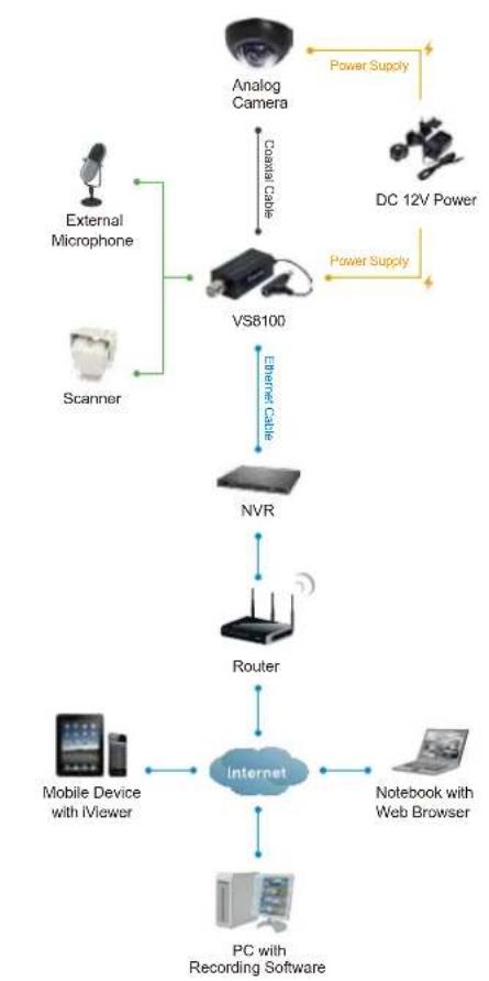
flowchart
graph TD
    A["Analog Camera"] -->|Power Supply| B["VS8100"]
    C["External Microphone"] --> D["VS8100"]
    E["Scanner"] --> D
    F["DC 12V Power"] -->|Power Supply| B
    G["NVR"] --> H["Router"]
    I["Mobile Device with iViewer"] --> J["Internet"]
    K["PC with Recording Software"] --> J
    L["Notebook with Web Browser"] --> J
    M["Coastal Cable"] --> D
    N["Ethernet Cable"] --> D
Dimensions
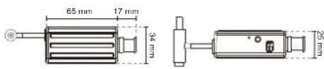
Compatible Accessories
Power Adapter

AA-221 DC 12V Power Adapter
All specifications are subject to change without notice. Copyright © 2013 VIVOTEK INC. All rights reserved.
Distributed by:

VIVOTEK INC.
6F, No.192, Lien-Cheng Rd., Chung-Ho, New Taipei City, 235, Taiwan, R.O.O. T: -820-2-82455282 | F: -820-2-82455532 E: sales@vipotek.com
VIVOTEK USA, INC.
2050 Ringwood Avenue, San Jose, CA 95131 T: 406-773-6202 | F: 406-773-6290 | E: salesusa@vivxek.com
Ver 1.0
Technology License Notice
AMR-NB Standard
THIS PRODUCT IS LICENSED UNDER THE AMR-NB STANDARD PATENT LICENSE AGREEMENT. WITH RESPECT TO THE USE OF THIS PRODUCT, THE FOLLOWING LICENSORS' PATENTS MAY APPLY:
TELEFONAKIEBOLAGET ERICSSON AB: US PAT. 6192335; 6275798; 6029125; 6424938; 6058359. NOKIA CORPORATION: US PAT. 5946651; 6199035. VOICEAGE CORPORATION: AT PAT. 0516621; BE PAT. 0516621; CA PAT. 2010830; CH PAT. 0516621; DE PAT. 0516621; DK PAT. 0516621; ES PAT. 0516621; FR PAT. 0516621; GB PAT. 0516621; GR PAT. 0516621; IT PAT. 0516621; LI PAT. 0516621; LU PAT. 0516621; NL PAT. 0516621; SE PAT 0516621; US PAT 5444816; AT PAT. 819303/AT E 198805T1; AU PAT. 697256; BE PAT. 819303; BR PAT. 9604838-7; CA PAT. 2216315; CH PAT. 819303; CN PAT. ZL96193827.7; DE PAT. 819303/DE69611607T2; DK PAT. 819303; ES PAT. 819303; EP PAT. 819303; FR PAT. 819303; GB PAT. 819303; IT PAT. 819303; JP PAT. APP. 8-529817; NL PAT. 819303; SE PAT. 819303; US PAT. 5664053. THE LIST MAY BE UPDATED FROM TIME TO TIME BY LICENSORS AND A CURRENT VERSION OF WHICH IS AVAILABLE ON LICENSOR'S WEBSITE AT HTTP://WWW.VOICEAGE.COM.
Electromagnetic Compatibility (EMC)
FCC Statement
This device compiles with FCC Rules Part 15. Operation is subject to the following two conditions.
■ This device may not cause harmful interference, and
■ This device must accept any interference received, including interference that may cause undesired operation.
This equipment has been tested and found to comply with the limits for a Class A digital device, pursuant to Part 15 of the FCC Rules. These limits are designed to provide reasonable protection against harmful interference when the equipment is operated in a commercial environment. This equipment generates, uses, and can radiate radio frequency energy and, if not installed and used in accordance with the installation manual, may cause harmful interference to radio communications. Operation of this equipment in a residential area is likely to cause harmful interference, in which case the user will be required to correct the interference at his own expense.
CE Mark Warning CE
This is a Class A product. In a domestic environment, this product may cause radio interference, in which case the user may be required to take adequate measures.
VCCI Warning
VIVOTEK Inc. cannot be held responsible for any technical or typographical errors and reserves the right to make changes to the product and manuals without prior notice. VIVOTEK Inc. makes no warranty of any kind with regard to the material contained within this document, including, but not limited to, the implied warranties of merchantability and fitness for any particular purpose.