AP370 - Access Point Aerohive - Free user manual and instructions
Find the device manual for free AP370 Aerohive in PDF.

| Product Type | Wireless Access Point |
| Model | Aerohive AP370 |
| Wireless Standard | 802.11ac Wave 2, dual-band (2.4 GHz and 5 GHz) |
| Maximum Data Rate | Up to 1.73 Gbps (2.4 GHz: 400 Mbps, 5 GHz: 1.33 Gbps) |
| MIMO Configuration | 3x3 MU-MIMO |
| Antenna Type | Internal omnidirectional antennas |
| Ethernet Ports | 2x 10/100/1000BASE-T (one with PoE+ input) |
| Power Supply | 802.3at PoE+ (Power over Ethernet) or optional 12V DC adapter |
| Power Consumption | 18W typical |
| Dimensions (H x W x D) | 1.7 x 8.3 x 8.3 in (4.3 x 21.1 x 21.1 cm) |
| Weight | 1.1 lb (0.5 kg) |
| Mounting | Ceiling mount plate included, wall mount optional |
| Management | Cloud-based HiveManager or on-premises HiveManager NG |
| Security Features | WPA2, WPA3, 802.1X, MAC filtering, rogue AP detection |
| Operating Temperature | 32°F to 104°F (0°C to 40°C) |
| Storage Temperature | -40°F to 158°F (-40°C to 70°C) |
| Humidity | 5% to 95% non-condensing |
| Certifications | FCC, CE, IC, Wi-Fi Alliance |
| LED Indicators | Power, Ethernet, 2.4 GHz, 5 GHz, status |
Frequently Asked Questions - AP370 Aerohive
User questions about AP370 Aerohive
0 question about this device. Answer the ones you know or ask your own.
Ask a new question about this device
Download the instructions for your Access Point in PDF format for free! Find your manual AP370 - Aerohive and take your electronic device back in hand. On this page are published all the documents necessary for the use of your device. AP370 by Aerohive.
USER MANUAL AP370 Aerohive
AEROHIVE PLENUM AND SUSPENDED MOUNT INSTALLATION INSTRUCTIONS
This document describes how to install Aerohive APs using the following mounting systems:
- "Plenum and Mount Installation" on page 1: This section explains how to mount an AP in the plenum above a dropped ceiling.
- "Suspended Mount Installation" on page 4: This section explains how to suspend an AP from a beam, post, strut, girder, or any object that can support its weight:
• AP121 - 11.6 oz (0.36 kg)
• AP141 - 13.5 oz (0.42 kg)
• AP230 - 1.6 lb (0.73 kg)
• AP330 - 1.5 lb (0.68 kg)
• AP350 - 2.38 lb (1.08 kg)
• AP370 - 11.6 oz (0.36 kg)
• AP390 - 13.5 oz (0.42 kg)
For the latest product documentation, compliance information, and software updates, visit www.aerohive.com/support.
PLENUM AND MOUNT INSTALLATION
Use the plenum mount kit (AH-ACC-BKT-PLENUM-300-100-KIT) to mount the AP models listed above in the plenum space above a dropped ceiling grid.
Plenum Mount Kit Contents
The plenum mount kit includes the following items:
- Plenum bracket for AP121, AP141, AP330, and AP350 models
- Plenum bracket for AP230, AP370 and AP390 models
- Hanger clip
- Hanger frame
You may need a pair of pliers to pinch the hanger clip into the mounting bracket.
Use the instructions and illustrations on the following pages to install an AP using the plenum mount kit.
- Insert the hanger clip into the center hole of the mounting bracket and squeeze it until the clip tabs pop upward through the smaller holes on either side.
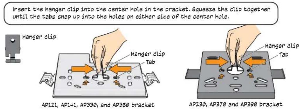
Insert the hanger clip into the center hole in the bracket. Squeeze the clip together until the tabs snap up into the holes on either side of the center hole.
- Attach the bracket and clip assembly to your AP. The following illustrations show how to do this for AP121, AP141, AP330, and AP350 models, and for AP230, AP370 and AP390 models.
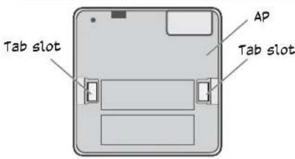
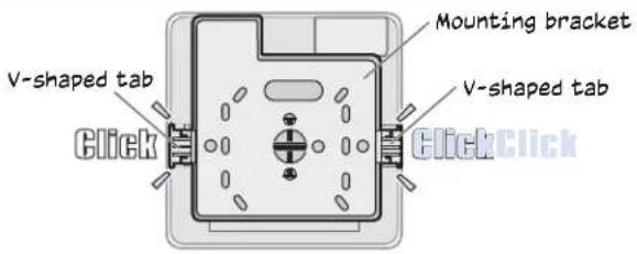
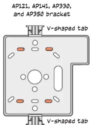
AP121, AP141, AP330, and AP350 models
Attach the bracket and clip assembly to the back of the AP by inserting the V-shaped bracket tabs into the tab slots on the AP. Make sure the bracket clicks securely into place.
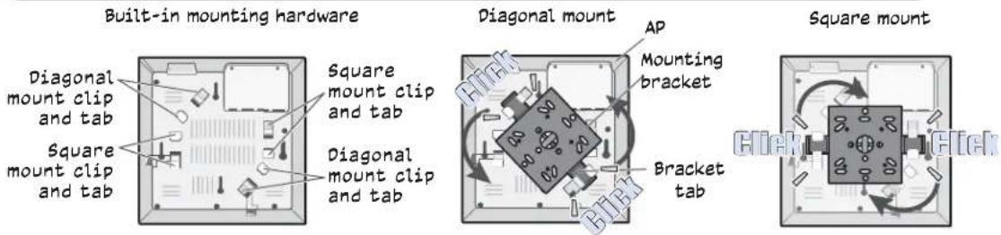
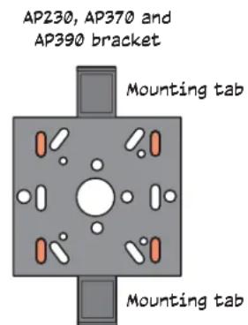
AP230, AP370 and AP390 models (AP370 shown here)
Attach the bracket and clip assembly to the back of the AP in either a diagonal or square position using the built-in mounting hardware on the AP. Slide the opposite edges of the bracket tabs under the mount tabs and rotate the bracket until it clicks into place.
-
Install external antennas if necessary.
-
Install the hanger frame into the ceiling plenum as shown in the following illustration.
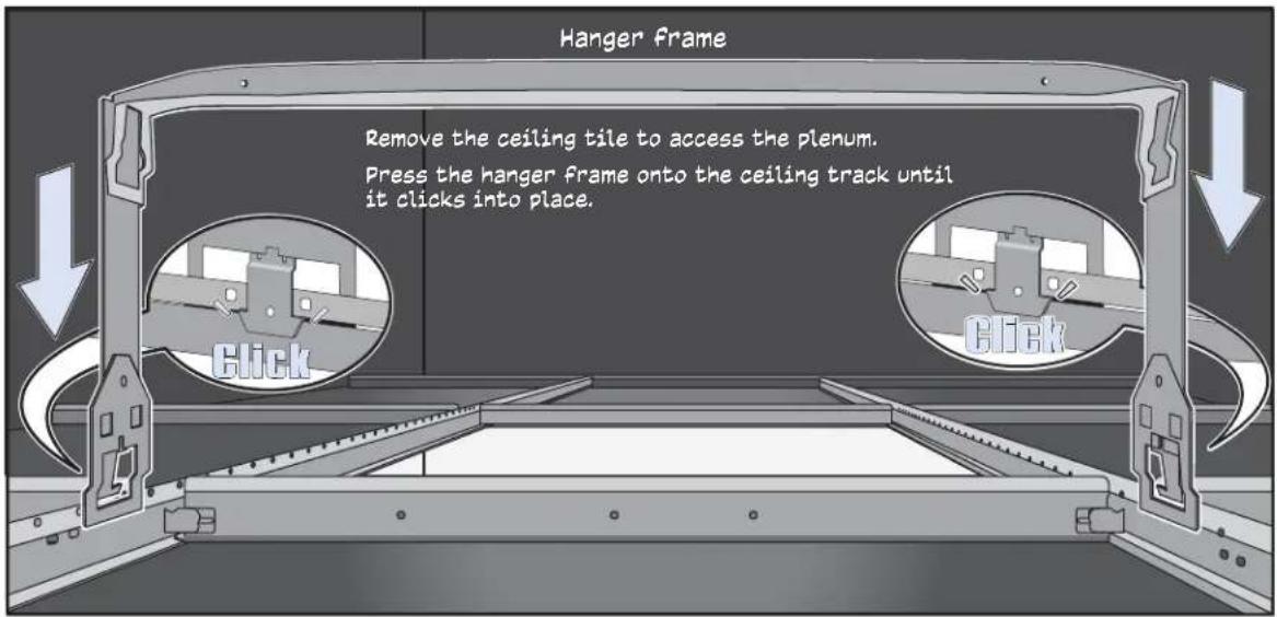
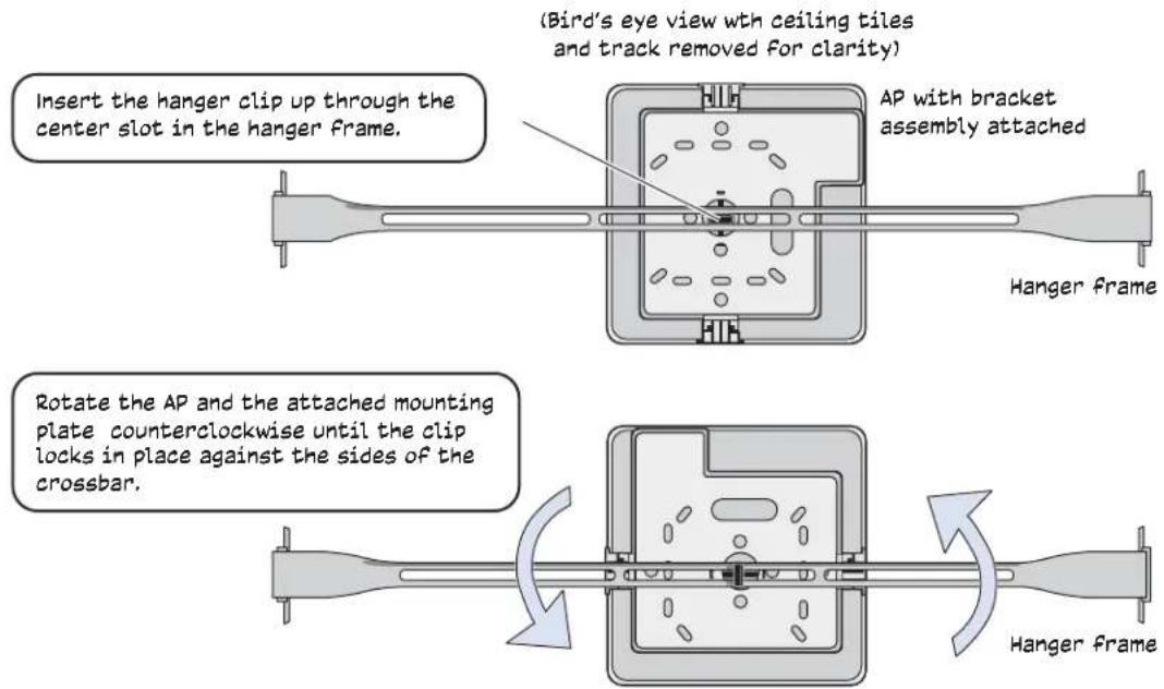
- Attach AP and mounting plate to the hanger frame as shown in the following illustration, which shows an AP121. This step is identical for all models.
- Connect an Ethernet cable to the network, and—if not using PoE—connect the power cord to a power source. Replace the ceiling tiles to complete the installation.
SUSPENDED MOUNT INSTALLATION
To suspend an AP from a horizontal beam, post, strut, or girder, use the suspended mount kit (AH-ACC-BKT-SUSPEND-300-100). Most of the illustrations in this section show an AP121. The installation steps are identical for all models, except that the AP230, AP370 and AP390 models use a different mounting bracket. For instructions for installing the mounting bracket on AP230, AP370 and AP390 models, see the illustration on page 2.
Suspended Mount Kit Contents
The suspended mount kit includes the following items:
- Mounting bracket for AP121, AP141, AP330, and AP350 models
- Mounting bracket for AP230, AP370 and AP390 models
- Hanging cable assembly:
- A quad-toggle, which consists of a small wire loop surmounting a metal bar from which four cable strands descend
- A mounting bracket, which connects the four strands to an Aerohive device
- Four oblong washers
- Wire rope with attached clip
- Locking device
Although no additional tools or accessories are required to install this kit, a 1/8" flat blade screwdriver is useful if you need to adjust the height of the hanging cable assembly.
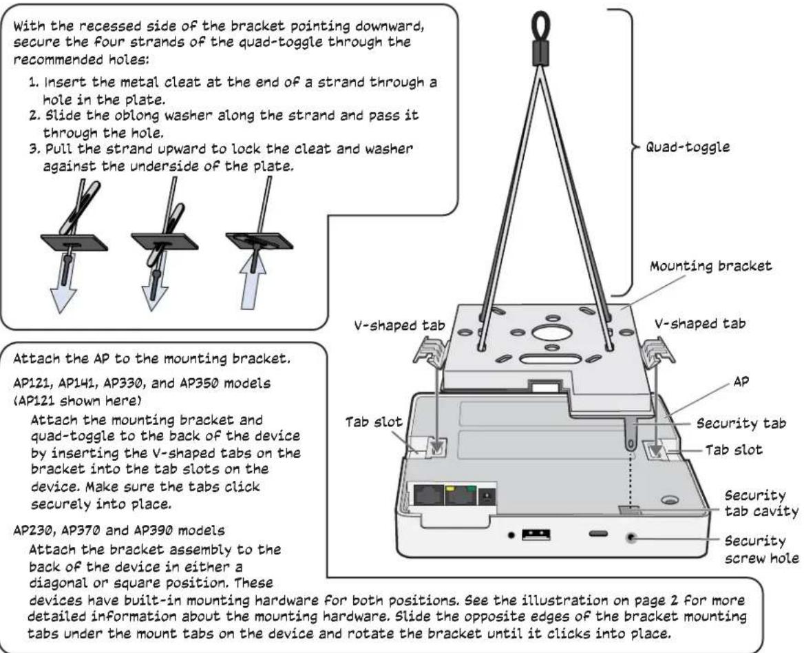
- To install an AP using the suspended mounting kit, attach the cable and quad-toggle assembly to the mounting bracket. The recommended bracket holes to use for the cables are shown for both mounting bracket styles in the following illustration.
The recommended holes for the cables are shaded.
- With the recessed side of the bracket facing down, secure the four strands of the quad-toggle through the recommended holes in the bracket, and then attach the bracket to the AP. Attach the bracket and quad-toggle assembly to the AP. An AP121 is shown in the illustration, but the process differs slightly for AP230, AP370 and AP390 models, which have built-in mounting hardware for attaching the brackets.
Attaching the Assembly to a Beam, Post, Strut or Girder
Use the following steps and illustration in to attach the AP assembly to a beam, post, strut, or girder. These steps apply to all AP models.
- Attach the assembly to the beam using the wire rope as shown in the illustration on the next page.
- Push the plain end of the wire rope—the end without the hook—through the side hole in the locking device in the direction indicated by the arrow on its side, and then pass it through the loop at the end of the quad-toggle.
- Insert the wire rope back through the center hole in the locking device, and then continue pulling it through the locking device until the AP is suspended at the height you want.
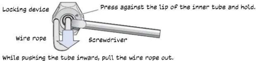
The center tube that runs through the locking device is designed to allow you to pull the rope wire up through it while preventing the rope from slipping back down. If you ever pull too much rope through and need to pull it back down, use a tool such as a screw driver to press against the inner tube in the locking device to release the rope. Then you can pull it back out. See "Height Correction" on page 6.
- Attach antennas to the antenna connectors on the AP if necessary, connect one or two Ethernet cables to the network, and—if not using PoE—connect the power cord to a power source.
Wrap the wire rope around a beam, clip the hook to the rope, and then pull the rope down until it is taut against the beam.

flowchart
graph TD
    A["Beam"] --> B["Clip"]
    B --> C["Pull downward on the rope"]
    D["Locking device"] --> E["Quad-toggle"]
    E --> F["Mounting bracket"]
    F --> G["AP"]
    H["Loop at top of quad-toggle"] --> I["Locking device"]
    I --> J["Push the wire rope down through the vertical side hole in the locking device and through the loop in the quad-toggle. Push the wire rope up through the center hole in the locking device. Pull the rope to raise the AP to the height you want."]
Height Correction
If you accidentally pull too much wire rope through the locking device, raising the AP too high, and you then need to lower it, do the following: Take a tool, such as a screwdriver with a 1/8" flat tip, and press it against the lip of the inner tube in the opposite direction from the arrow on the outside of the locking device. This releases its grip on the rope, allowing you to pull the rope out the same way it was inserted. While maintaining pressure on the tube, adjust the rope until the device is at the height you want. When you are satisfied, stop pressing against the tube so that it can regain its grip on the rope.
Copyright © 2014 Aerohive Networks, Inc. All rights reserved.
Aerohive Networks, AerohiveHiveOS, and HiveManager are trademarks of Aerohive Networks, Inc. The Aerohive Networks logo is a registered trademark of Aerohive Networks. All other trademarks and registered trademarks are the property of their respective companies.
P/N 330082-04