StudioLive 328AI - Pregnant PRESONUS - Free user manual and instructions
Find the device manual for free StudioLive 328AI PRESONUS in PDF.

| Product Type | Active PA speaker (2-way) |
| Brand | PreSonus |
| Model | StudioLive 328AI |
| Dimensions (H x W x D) | 457 x 305 x 279 mm (18 x 12 x 11 in) |
| Weight | 13.6 kg (30 lb) |
| Amplifier Power | 1200W Class D (peak) |
| Woofer | 8-inch (203 mm) ferrite magnet |
| Tweeter | 1-inch (25 mm) compression driver |
| Frequency Response | 50 Hz – 20 kHz (±3 dB) |
| Maximum SPL | 128 dB (peak) |
| Coverage Angle | 90° x 60° (H x V) |
| Power Requirements | 100–240 VAC, 50/60 Hz |
| Input Connectors | 2x XLR-1/4" combo, 1x RCA, 1x Bluetooth |
| Output Connectors | 1x XLR Mix Out, 1x XLR Thru |
| Housing Material | Polypropylene, steel grille |
| Installation Options | Pole mount (36 mm), floor monitor, flying (optional) |
| Protection Features | Overload, thermal, limiter, subsonic filter |
| Cleaning | Use a dry cloth; avoid solvents |
| Spare Parts Availability | Contact PreSonus support or authorized dealers |
| Repairability | Serviced by qualified technicians only |
Frequently Asked Questions - StudioLive 328AI PRESONUS
User questions about StudioLive 328AI PRESONUS
0 question about this device. Answer the ones you know or ask your own.
Ask a new question about this device
Download the instructions for your Pregnant in PDF format for free! Find your manual StudioLive 328AI - PRESONUS and take your electronic device back in hand. On this page are published all the documents necessary for the use of your device. StudioLive 328AI by PRESONUS.
USER MANUAL StudioLive 328AI PRESONUS
StudioLive AI-Series Active Integration PA Speakers
Digital PA System with Active Integration
Owner's Manual
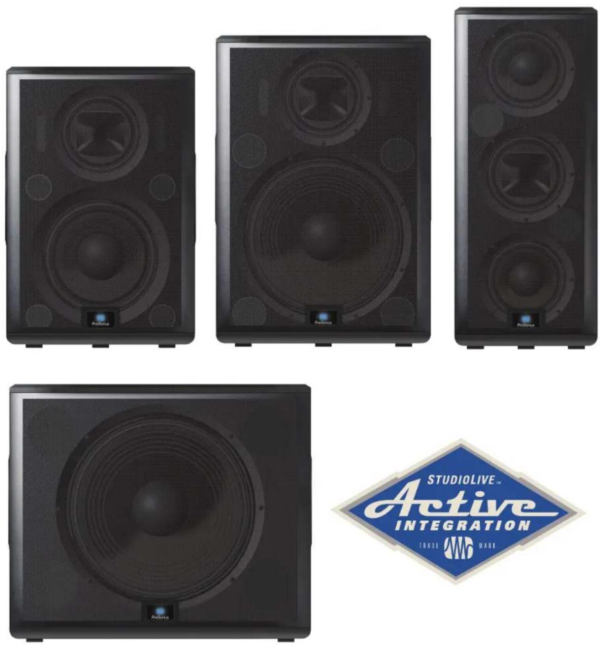
Table of Contents
1 Overview — 1
1.1 Introduction — 1
1.2 About This Manual — 1
1.3 Summary of StudioLive AI-Series Loudspeaker Features — 2
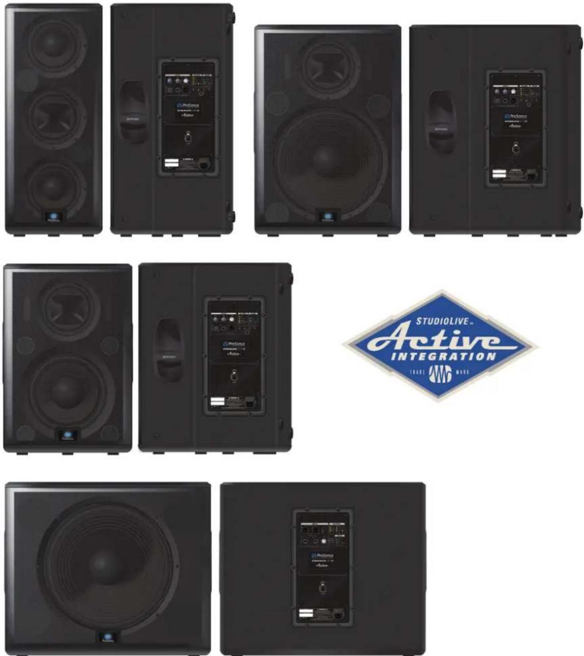
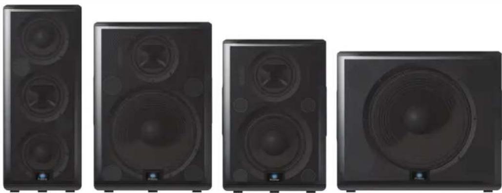
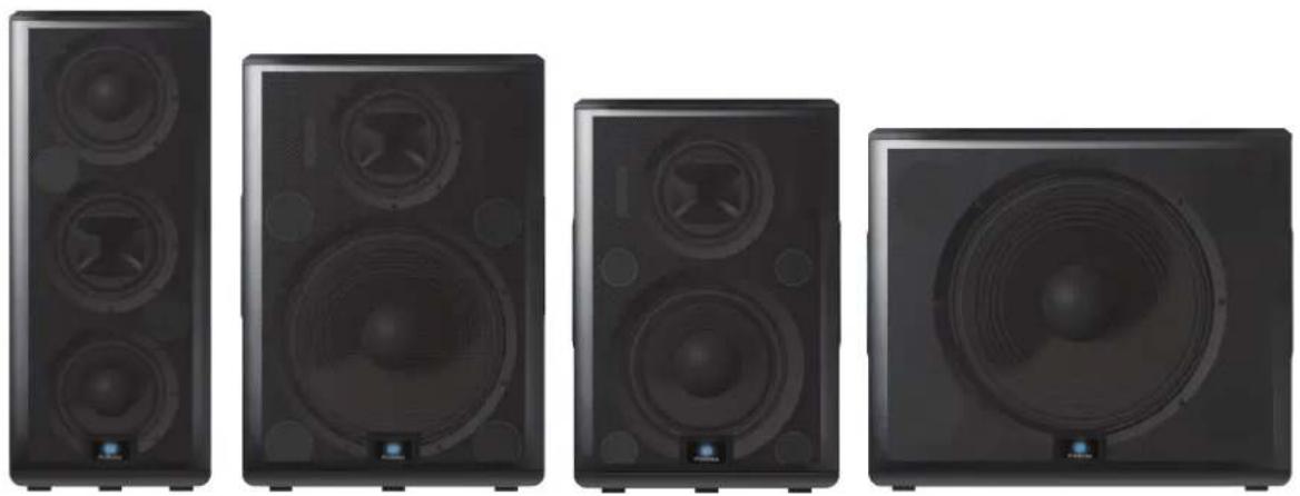
1.3.1 Full-range Models (312AI, 315AI, and 328AI) — 2
1.3.2 18sAl Subwoofer — 2
1.3.3 SL Room Control — 3
1.4 What is in the Box — 4
2 Getting Started — 5
2.1 Level Setting Procedure (Full-Range) — 5
2.2 Level Setting Procedure (18sAI) — 8
3 Hookup — 12
3.1 Rear-Panel Connections and Controls — 12
3.1.1 Full-Range Models: 312AI, 315AI, and 328AI — 12
3.1.2 18sAl Subwoofer — 14
3.2 Onboard Performance Monitoring — 15
3.2.1 A Note About the Limiter — 16
3.3 Networking Connections and Controls — 16
3.4 Power — 17
3.5 Basic Hookup Diagram — 18
3.6 Typical Band Setup Diagram — 18
3.7 Typical Venue Setup Diagram — 19
3.8 Typical Corporate Conference Setup Diagram — 19
4 System Configuration — 20
4.1 Recognizing Problem Rooms — 20
4.1.1 Vertical Coverage — 21
4.1.2 Wall and Corner Loading — 21
4.1.3 Maintain a High Direct-to-Reverberant Ratio — 22
4.2 Delay Systems — 22
4.2.1 Delay Basics — 23
4.2.2 Sub Alignment — 24
4.2.3 Real-World Delay System Example — 26
4.2.4 System Configuration Suggestions — 26
4.2.5 Stereo System — 27
4.2.6 Mono Cluster with Down Fill — 27
4.2.7 LCR Systems — 28
4.2.8 Monitor Systems — 28
4.3 Rigging and Safety — 29
4.3.1 Safety is the Priority — 29
4.3.2 Ground Stacking — 30
4.3.3 Pole Mount — 30
4.3.4 Suspending the Loudspeaker — 31
4.3.4 Precautions — 32
5 Technical Information — 33
5.1 Specifications — 33
5.2 System Block Diagrams — 35
5.2.1 Full-range Models — 35
$$ 3 2 8 \mathrm{AI} - 3 5 $$
$$ 3 1 2 - 3 1 5 \mathrm{AI} - 3 6 $$
5.2.2 18sAl Subwoofer — 37
5.3 Mechanical Drawings — 38
5.3.1 StudioLive 312AI — 38
5.3.2 StudioLive 315AI — 38
5.3.3 StudioLive 328AI — 39
5.3.4 StudioLive 18sAI — 39
5.4 Optional Accessories — 40
6 Troubleshooting and Warranty — 41
6.1 Support and Troubleshooting — 41
6.2 Warranty — 42
1 Overview
1.1 Introduction
Thank you for purchasing a PreSonus® StudioLive™ AI-series Active Loudspeaker. PreSonus Audio Electronics has designed StudioLive AI-series loudspeakers utilizing high-grade components to ensure optimum performance throughout the life of your PA system. StudioLive AI-series loudspeakers are the first affordable, active PA speaker systems that deliver studio-monitor accuracy on stage—exceptionally clear, coherent sound—while supplying the features and protection systems required to mix a live show that sounds great in a wide variety of venues and with any musical genre.
These features include wireless and wired control of all setup and monitoring functions, using an iPad® or laptop, including customized signal delay and EQ processing. Loaded with unprecedented amounts of DSP, an 8-inch custom CoActual™ coaxial speaker, Fulcrum Acoustic's TQ™ Temporal Equalization algorithms, and more, StudioLive AI-series loudspeakers break new ground for live-music speaker systems.
We encourage you to contact us with questions or comments regarding this product. PreSonus Audio Electronics is committed to constant product improvement, and we value your suggestions highly. We believe the best way to achieve our goal of constant product improvement is by listening to the real experts: our valued customers. We appreciate the support you have shown us through the purchase of this product.
For technical support, please see Section 6.1: Troubleshooting.
1.2 About This Manual
This manual covers hardware features and functions for all three full-range AI loudspeakers (312AI, 315AI, and 328AI) as well as the companion 18sAI subwoofer. We suggest that you use the manual to familiarize yourself with the features, applications, and connection procedures for your StudioLive AI-series loudspeakers before trying to set up and operate them.
Except for low-frequency driver configuration and some technical specifications (such as weight, frequency response, and maximum SPL), the features and functions of the three full-range models are the same. In many respects, the functions of the 18sAl are also the same. Whenever possible these features and functions will be described for the entire line. Unless preceded by "full-range," the term "loudspeaker" will refer to both full-range models and the subwoofer.
Throughout this manual you will find Power User Tips highlighting unique aspects of StudioLive AI-series loudspeakers, as well as explanations of various audio terms. In addition, you will find tutorials that cover the basics of room acoustics and speaker placement.
Thank you, once again, for buying our product. We are confident that you will enjoy your StudioLive AI loudspeakers!
1.3 Summary of StudioLive AI-Series Loudspeaker Features
1.3.1 Full-range Models (312AI, 315AI, and 328AI)
- Unique coaxial design integrates a custom-designed, 8-inch, ferrite midrange driver and 1.75-inch titanium compression driver with Temporal Equalization ^™ and Coaxial Speaker Coherence Alignment.
- 12-inch/15-inch/2x8-inch ferrite, low-frequency transducer
•2,000 watt, Class D triamplification - Active Integration™ 32-bit floating-point DSP with asymmetric three-way crossover, performance contouring, dynamic limiting, excursion limiting, and Temporal Equalization™, which compensates for horn reflection and manages linear time correction and amplitude-anomalies correction.
-
Wireless or wired networking with free SL Room Control software for Mac ^® , Windows ^® , and iPad ^® enables complete setup, tuning, and monitoring.
-
Input mixer with:
- XMAX™ Class A solid-state mic preamp with 12V phantom power
•Line input with attenuation
•Balanced Mix output
•4 DSP Contours optimized for:
•Normal — live front-of-house
•LBR Source — low bit-rate source audio
•Floor Monitor — stage wedge
- Speaker level control
• Universal switch-mode power supply with power-factor correction
•Comfortable, ergonomic handles
- Integrated M10 fly points and pole mounts
•Ships with Ethercon connection for wired remote control
•Ships with USB Wi-Fi module for wireless remote control
•Optional Dante card
1.3.2 18sAI Subwoofer
- 18-inch transducer with 1,000 watt, Class D amplifier
•Active Integration 32-bit, 96 kHz DSP with variable crossover, dynamic limiting, and excursion limiting - Stereo line inputs (XLR- 1/4'' combo)
- Switchable stereo/summed-mono line thrus (XLR)
- Adjustable alignment delay presets (0, 1, or 2 meters)
•3 DSP Contours optimized for:
•Normal — live front-of-house
•Extended LF — bigger bass sound
-User — customizable preset
- Integrated pole insert and interlocking stacking provisions
• Universal switch-mode power supply with power-factor correction
•Comfortable, ergonomic handles
•Ships with Ethercon connection for wired remote control
•Ships with USB Wi-Fi module for wireless remote control
•Optional Dante card
- Optional Sub Dolly and pull-tested Sub Pole to mount a full-range system atop the 18sAI
1.3.3 SL Room Control
PreSonus StudioLive AI-series Active Integration™ PA speakers offer a wealth of system-control and performance-monitoring features that give you unprecedented control. The secret to accessing these features is SL Room Control, a speaker-management system and remote-control/monitoring software for Mac® OS X, Windows®, and iOS®.
To use SL Room Control, you simply create a local area network using a wireless router and connect your StudioLive AI speakers with the included USB 2.0 Wi-Fi LAN adapter or onboard Ethercon connection. Connect your Mac, PC, or iPad® to the same Wi-Fi network and launch SL Room Control to unlock your StudioLive AI speaker system's full power. SL Room Control's Network Setup wizard makes it easy to network your entire system.
- Remote control over:
•Polarity invert (18sAl)
•DSP Contours
•100 Hz highpass filter (312AI, 315AI, 328AI)
•Network Setup wizard
•Network scanning to automatically detect all speakers
•Network browser
•Performance monitoring over:
•Excursion limiting
•Over temperature
- ADC clip detection
•Power-amp soft limiting
• Group speaker management with level control and 31-band graphic EQ
•8-band parametric EQ (312AI, 315AI, 328AI)
•8 notch filters (312AI, 315AI, 328AI)
- Limiter
•Speaker delay, up to 500 ms
- DSP input level
- EQ preset browser
- Custom labels and comments field for each speaker
- Preset save and load
- Create and store User Operation mode onboard each speaker for use away from SL Room Control
Note: Complete information about SL Room Control can be found in the SL Room Control Reference Manual.
1.4 What is in the Box
In addition to this manual, your StudioLive package contains the following:
•The loudspeaker product
- Locking IEC power cable

•USB Wireless LAN Adapter
•SL Room Control download instructions
•PreSonus Health Safety and Compliance Guide
2 Getting Started
Before you begin, here are a few general rules of thumb:
• Always make sure your loudspeakers are powered off when making connections.
- Do not allow your inputs to clip. Watch the Clip LED on the back of your loudspeaker. When this LED illuminates, it indicates that the analog-to-digital converters are in danger of being overdriven. Overdriving the converters will cause digital distortion, which sounds terrible.
- Your full-range loudspeaker provides attenuation control only for the speaker and line levels. If you are not getting adequate volume with these controls turned all the way up (0 dB), make sure that your mixer is properly gain-staged and that you are using enough loudspeakers for your application.
Your PA and studio equipment should be powered on in the following order:
- Sound sources (keyboards, direct boxes, microphones, etc.) connected to your mixer
•Mixer
•StudioLive AI-series Loudspeakers
When it's time to power down, your system should be turned off in the reverse order.
Now that you know what not to do, let's get some audio going! The following level-setting tutorials cover best practices that can be applied to nearly every application. The first tutorial covers level setting for the full-range models only; the second tutorial describes proper level setting for a system that includes one 18sAI subwoofer and two full-range AI-series loudspeakers.
2.1 Level Setting Procedure (Full-Range)
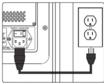
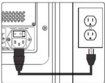
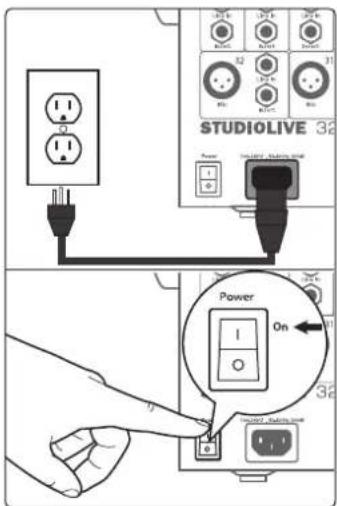
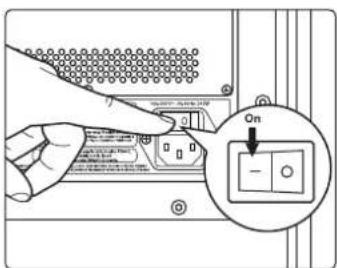
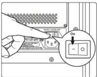
- With the power switch in the Off position, connect the locking IEC plug to the IEC socket connection on the back of the loudspeaker and plug it into a grounded AC outlet or surge protector.
Power User Tip: While a locking IEC cable is ideal for permanent installation, be careful that this cable cannot be tripped over in ground-stacked applications, as this is a toppling risk.
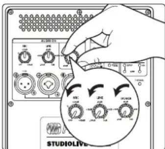
- Turn the Mic, Line, and Speaker level knobs fully counterclockwise, to the lowest position.
2 Getting Started
2.1 Level Setting Procedure (Full-Range)
StudioLive AI-Series Loudspeaker
Owner's Manual
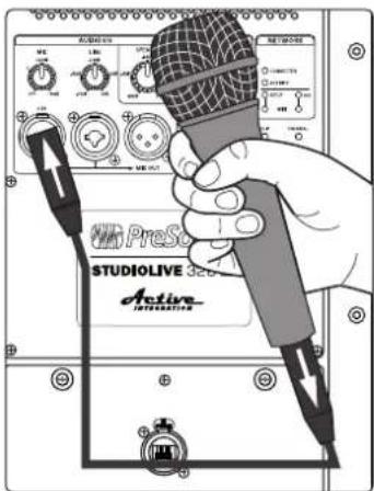
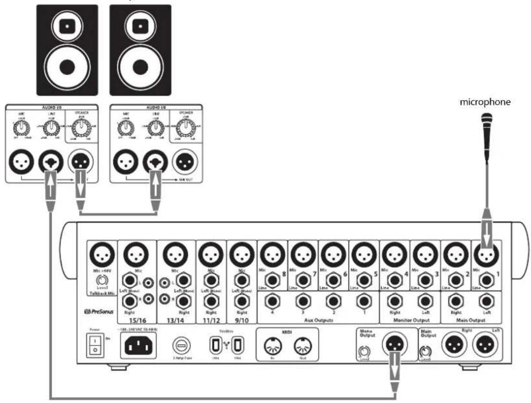
- If you're using the StudioLive full-range loudspeaker as a mixer, connect a microphone to the Mic input with a standard XLR cable.
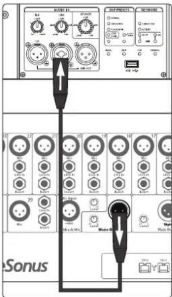
- Connect your line-level source (such as a PreSonus StudioLive digital mixer) to the Line input. The Line input is a combo connection that accepts a balanced 14 " TRS or XLR cable.
Power User Tip: If you are running a stereo system, connect the Left output of your mixer to the Left loudspeaker's line input, and the Right output to the Right loudspeaker's line input.
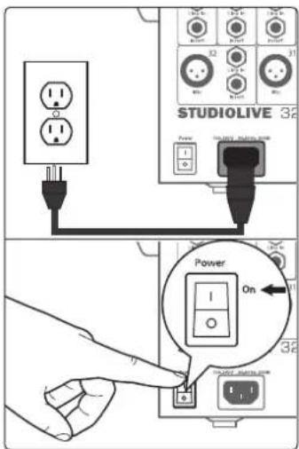
- Power on your line-level source.
2 Getting Started
2.1 Level Setting Procedure (Full-Range)
StudioLive™ AI-Series Loudspeaker
Owner's Manual
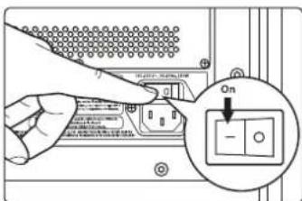
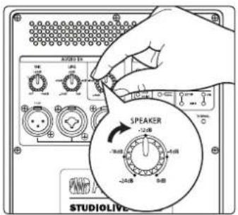
- Power on your StudioLive loudspeaker.
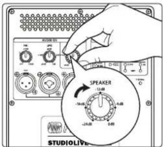
- Turn the Speaker level knob to the 12 o'clock position.
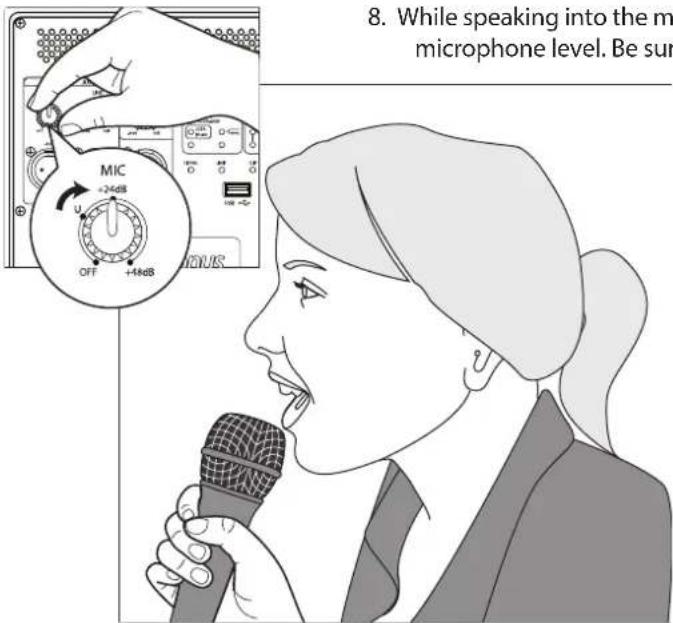
- While speaking into the microphone, use the Mic level knob to adjust the microphone level. Be sure that you are not standing directly in front of the loudspeaker while doing this, as doing so could result in feedback. If you are not using the Mic input, it is recommended that you leave this knob in the Off position so as not to introduce noise into your signal path.
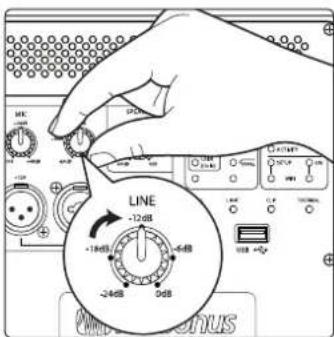
- With audio playing through your line-level source, turn the Line level knob until you have achieved a comfortable listening volume. If you are not using the Line input, it is recommended that you leave this knob in the -24 dB position so as not to introduce noise into your signal path.
2 Getting Started
2.2 Level Setting Procedure (18sAI)
StudioLive AI-Series Loudspeaker
Owner's Manual
- Both the Microphone and Line inputs should be set so that the green Signal LED is illuminated most of the time, but the red Clip LED illuminates only with the highest transient peaks or not at all.
-
If more output level is required, turn the Speaker level knob clockwise. This is the master level control for your loudspeaker. It controls the mixed signal of the Mic and Line inputs.
-
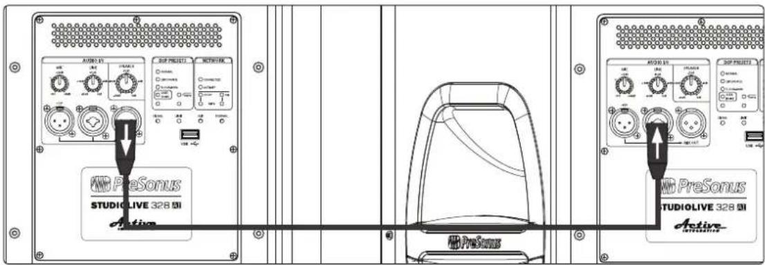
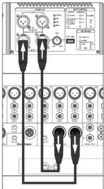
If you are using the input mixer of one loudspeaker to connect a microphone and a line-level source, or if you are running a mono system, connect the Mix Out from the loudspeaker to which your sources are connected to the line input of the second loudspeaker and repeat steps 9-11.
2.2 Level Setting Procedure (18sAI)
- With the power switch in the Off position, connect the locking IEC plug to the IEC socket connection on the back of each loudspeaker and plug it into a grounded AC outlet or surge protector.
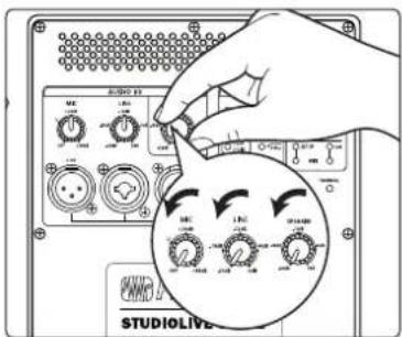
- Turn the Mic, Line, and Speaker level knobs on your full-range loudspeakers fully counterclockwise to the lowest position.
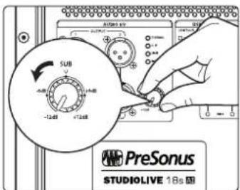
- Turn the Sub level knob on your 18sAI counterclockwise to the lowest position.
-
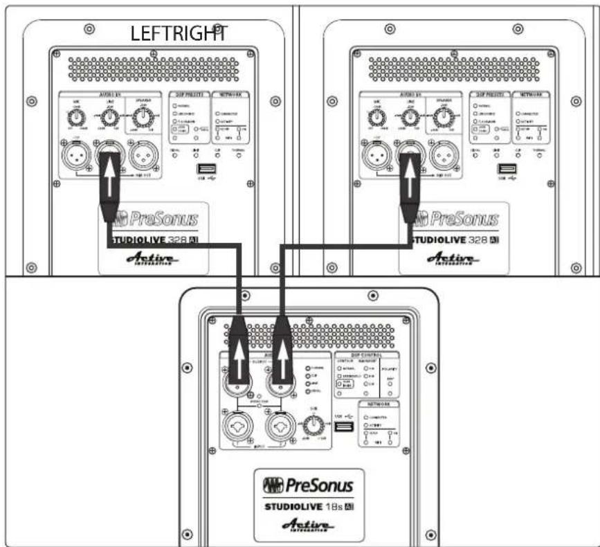
Connect your line-level source (e.g., a StudioLive mixer) to the Line inputs. This is a combo jack that accepts a balanced 14 " TRS or XLR plug. If you are connecting a stereo source, the left side should be connected to Input 1, and the right side should be connected to Input 2.
-
Connect Output 1 of your 18sAI to the left full-range loudspeaker and Output 2 of your 18sAI to the right full-range loudspeaker.
2 Getting Started
2.2 Level Setting Procedure (18sAI)
StudioLive AI-Series Loudspeaker
Owner's Manual
- Power on your line-level source.
- Power on your 18sAl.
- Power on your StudioLive AI full-range loudspeakers.
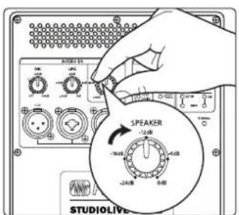
- Turn the Speaker level knob on your full-range loudspeakers to the 12 o'clock position.
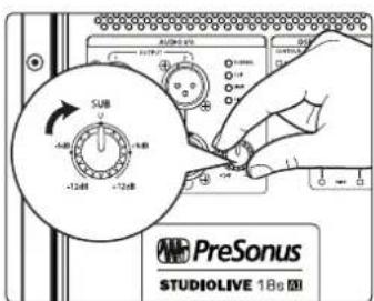
- Turn the Sub level knob on your 18sAI to the 12 o'clock position. This is unity gain.
- Turn the Line level knob on your full-range loudspeakers to the fully clockwise position.
- The line-level inputs should be set so that the green Signal LED is illuminated most of the time, but the red Clip LED illuminates only with the highest transient peaks or not at all. If your line-level source is clipping the inputs on your 18sAl, you will need to turn down the source's output level.
- If more high-frequency output level is required, turn the Speaker level knob clockwise on your full-range loudspeakers. In most cases, the level should be set the same on both loudspeakers.
- Adjust the Sub level control on your 18sAI to balance the low-frequency content level to taste.
- The full-range loudspeakers offer a highpass filter centered at 100 Hz. With or without this filter engaged, the full-range loudspeakers are time-aligned to pair with the 18sAI to create a true 4-way system. Experiment with engaging and disengaging this filter to get the desired effect. Without the filter engaged, your system will provide bigger low-frequency content. Engaging the filter will provide a more linear frequency response. In either case, please remember that engaging/disengaging the highpass filter will also adjust the time-alignment of the speaker and it will mute momentarily until all filters and timing settings have been loaded in the DSP.
3 Hookup
3.1 Rear-Panel Connections and Controls
3.1.1 Full-Range Models: 312AI, 315AI, and 328AI
natural_image
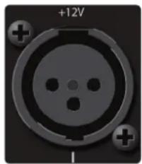
Close-up of a circular electronic component with three holes and a +12V label (no readable text or symbols beyond basic markings)Microphone Input. Your AI-series full-range loudspeaker is equipped with a PreSonus XMAX™ microphone preamplifier for use with most microphone types. The XMAX solid-state preamplifier has a Class A input buffer, followed by a dual-servo gain stage. This arrangement results in ultra-low noise and wide gain control, allowing you to boost signals without increasing unwanted background noise.
A 12V phantom-power supply is present on the microphone input at all times.
XLR connector wiring for phantom power:
Pin 1 = GND Pin 2 = +12V Pin 3 = +12V
WARNING: Phantom power can severely damage some dynamic microphones, especially ribbon mics. Therefore, we recommend reviewing your microphone's documentation prior to use to ensure that it will not be damaged by low-level phantom power. Note that the supplied 12V may not be adequate for some condenser mics.
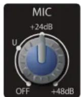
Microphone Input Level. Adjusts the gain level of the Microphone input.
Power User Tip: It is very important to properly adjust this control in order to minimize noise and avoid overload distortion. Follow the level-setting instructions in Section 2.1 before operating a channel.
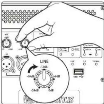
natural_image
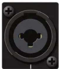
Close-up of a black circular mechanical component with three ports and mounting holes (no text or symbols visible)Line Input. This is a balanced XLR / 1/4" TRS combo connection for line-level input. Use the Line input to connect the loudspeaker to a StudioLive digital mixer or other mixing console, either directly or through the Line in/out connectors on a StudioLive S18sAI subwoofer. The Line input will accept a signal level of up to +24 dBu before clipping.
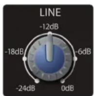
Line Input Level. Adjusts the gain level of the Line input. Like the Microphone Input Level, it is very important to properly adjust this control in order to minimize noise and avoid overload distortion. This knob provides attenuation control only. In most situations, you will set this control fully clockwise to 0 dB. However, if your line-level source has a very high-gain output, you may need to attenuate it to avoid clipping the ADC.
Note: As with any amplifier or active loudspeaker, plugging in a microphone or a line-level input device, will create a momentary spike in the audio output of your StudioLive full-range loudspeaker. Because of this, it is highly recommended that you turn down the channel trim or power down your loudspeaker before changing connections. This simple step will add years to life of your audio equipment.
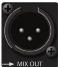
Mix Out. A balanced Mix output is provided on an XLR-M connector. The Mix Out connection is used to send signals connected to the inputs of your loudspeaker to other StudioLive-series loudspeakers. The Mix output signal is the same as the signal sent to the loudspeaker's internal amplifier, and it may be derived from the microphone input, the line input, or a mix of both.
Power User Tip: When cascading to the Line Input on a second speaker from the Mix Out, set the Line Input Level on the second speaker to 0 dB and use the Speaker Level control to attenuate the volume as needed. In this way, you will maximize signal clarity and minimize distortion.
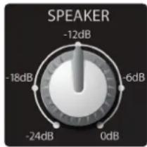
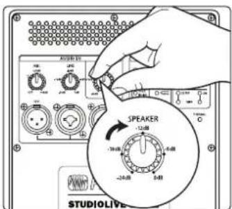
Speaker Level. This control attenuates the output level of your StudioLive full-range loudspeaker's internal amplifier. As with the Line Input level control, in most situations, you can set this knob fully clockwise to the 0 dB setting.
Note: The Mix output level is not affected by the Speaker level control.
Power User Tip: The Speaker level control allows you to set the maximum output level of your speaker. This is especially useful in situations where there is an SPL ordinance in effect or where your audience and your front-of-house engineer have different opinions about how loud a performance should be.
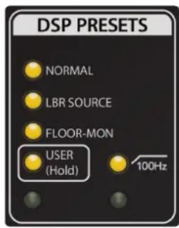
DSP Contours. Your StudioLive AI-series loudspeaker is equipped with three DSP contour presets. These contours change the character of your StudioLive loudspeaker in a fundamental way, adjusting FIR filters, alignment, and crossover settings to customize your loudspeaker for one of three applications:
- Normal. Normal mode sets dynamics and equalization for optimum performance for live music. This mode is suitable for use with PreSonus StudioLive consoles and most other mixing consoles.
- LBR Source. AI-series loudspeakers are designed to provide high-resolution, accurate reproduction of high-quality recordings and live mixes. When low-bit-rate MP3s are played, the unusual clarity of AI speakers may reveal the artifacts of MP3 compression to an unflattering degree. The LBR Source contour is specifically designed to reduce the audibility of these artifacts.
- Floor Monitor. Floor mode sets dynamics and equalization for optimum results when the loudspeaker is used as a floor monitor.
Because these contours are changing fundamental tuning parameters, your StudioLive AI-series loudspeaker will mute momentarily while the new parameters load. Because of this, do not change the DSP contour once your performance has begun. Press the recessed button below the User LED repeatedly to step through the three contours.

User Layer. The User Layer accesses DSP settings that you create using SL Room Control software. This layer contains custom EQ, High Pass Filter, Delay, and Group settings. Parameter adjustments in SL Room Control are automatically stored in the DSP memory in real-time. You can also create and load user presets from SL Room Control. For more information on SL Room Control, see the SL Room Control Reference Manual. Press and hold the recessed button below the User LED to turn the User Layer on or off. This will apply the User Layer parameters on top of the currently selected DSP contour when you are not connected to SL Room Control.
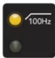
100 Hz High Pass Filter. This option engages a highpass filter that removes frequency content below 100 Hz. Engaging the highpass filter will also adjust phase and time-alignment settings. Because of this, your loudspeaker will mute momentarily while these new internal settings are being applied. While these settings are optimized for use with the StudioLive 18sAI, you can use this mode with any subwoofer to remove unwanted low-frequency content.
Power User Tip: The three full-range loudspeakers are phase and time-aligned to form a true 4-way system when paired with an 18sAI subwoofer, with or without the 100 Hz High Pass Filter engaged. With most 4-way systems, leaving frequency content below 100 Hz in the full-range loudspeaker can introduce destructive cancellations with the highest frequencies that are reproduced by the subwoofer. StudioLive AI-series loudspeakers are designed to avoid this problem when combined with an 18sAI subwoofer. This means that for applications where a frequency overlap at 100 Hz is beneficial, you can achieve bigger bass sound without any extra effort. For applications that require a more linear frequency response between the subwoofer and full-range content, simply engage the highpass filter on the full-range AI-series loudspeaker. This will also readjust the phase and time-alignment to keep it in phase with the 18sAI subwoofer, enabling you to create the best four-way system for your application.
3.1.2 18sAl Subwoofer
natural_image
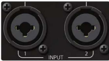
Close-up of two circular electronic components with labeled pins (1 and 2), no readable text or symbols beyond labelsLine Inputs. The 18sAI features two line-level inputs. These balanced combo connections are provided to connect your subwoofer to a StudioLive digital mixer or other mixing console. The line inputs will accept up to a +24 dBu source before clipping.
Power User Tip: Two inputs are provided in order to accept a stereo signal from the output of the mixing console. Both channels should be connected, as the low-frequency content from both channels of a stereo signal is summed before the lowpass filter.
However, if the mixing console output signal is mono only, or if you are sending low-frequency channels (bass, kick, keyboards, etc.) to a separate aux or subgroup output for the subwoofer only, either input may be used. If you are using two 18sAI subwoofers and running your system in stereo, connect the Left side to Input 1 of the left 18sAI and the Right side to Input 1 of the right 18sAI.
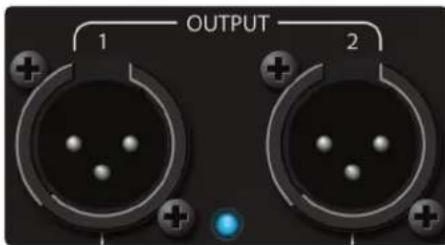
Outputs. Two line-level outputs (1 and 2) are provided to pass the stereo signal from the subwoofer to full-range StudioLive AI-series loudspeakers. The outputs are parallel to Inputs 1 and 2, respectively.
For more information on connecting multiple loudspeaker systems, see the hookup diagrams in Sections 3.5 through 3.8.

Mono Switch. The Mono switch sums Inputs 1 and 2 and patches the summed signal to Outputs 1 and 2. This feature is especially useful when running stereo full-range systems with multiple mono subwoofers.
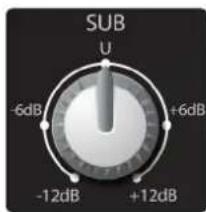
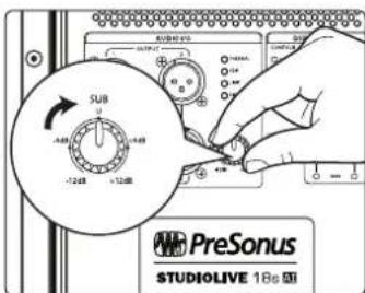
Sub Level. The Sub level knob determines the output level (volume) of the subwoofer power amplifier. It has no effect on the signal level from Outputs 1 and 2. You can adjust the speaker level from -12 dB to +12 dB. Signal level sent to the subwoofer outputs is not affected by the Sub level control.
Power User Tip: A subwoofer can significantly change the frequency response of a full-range system. A 4-way system with a subwoofer will be 6 to 18 dB hotter below 80 to 100 Hz. Set the appropriate level for your subwoofer before adjusting your system EQ. When used with a StudioLive mixer and StudioLive AI-series full-range loudspeakers, the Sub level knob can typically be set to 0 dB.
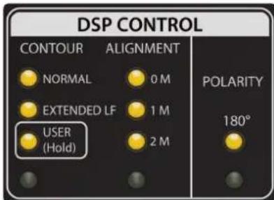
DSP Contours. Your 18sAI Subwoofer is equipped with two DSP contours. These contours change the character of your StudioLive loudspeaker in a fundamental way, adjusting FIR filters, alignment, and crossover settings to customize your loudspeaker for one of two applications:
• Normal. Optimized for use with mixers and full-range loudspeakers.
- Extended LF. Inserts a subharmonic bass synthesizer to extend extreme deep bass response.
Because these contours are changing fundamental tuning parameters, your 18sAI will mute momentarily while the new parameters load. Because
of this, do not change the DSP Contour once your performance has begun. Press the recessed button below the User LED repeatedly to step between the contours.
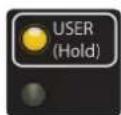
User Layer. The User Layer accesses DSP settings that you create using SL Room Control software. This layer contains Low Pass Filter, Delay, and Group settings. Parameter adjustments in SL Room Control are automatically stored in the DSP memory in real-time. You can also create and load user presets from SL Room Control. For more information on SL Room Control, see the SL Room Control Reference Manual. Press and hold the recessed button below the User LED to turn the User Layer on or off. This will apply the User Layer parameters on top of the currently selected DSP Contour when you are not connected to SL Room Control.
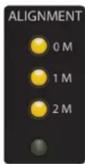
Alignment. Adds delay time to the subwoofer. Press the recessed button under the Alignment LEDs to step through the three settings.
OM. Select this setting when the full-range system is directly over the subwoofer. No delay is added to the subwoofer amplifier output.
1M. Select this setting when the subwoofer is about one meter from the full-range loudspeaker—a typical distance when the loudspeaker is on an adjacent tripod stand. A delay of about 2.9 ms is introduced to the signal that is output through the subwoofer amplifier.
2M. Select this setting when the subwoofer is about two meters from the full-range loudspeaker—typical when the full-range system is on the stage and the subwoofer is on the floor. A delay of about 5.9 ms is introduced to the signal that is output through the subwoofer amplifier.
Power User Tip: The Alignment delay setting compensates for the cancellation or reinforcement of low frequencies when the same frequencies are reproduced by two sound sources that are set some distance apart. Low frequencies in the crossover region between full-range and subwoofer have wavelengths that are several feet long (the wavelength of a 150 Hz wave is about 7.5 ft!), and reinforcement and cancellation will occur as the waves interact in the room. The Alignment delay provides compensation for this effect when the loudspeaker is about the same distance away from, or in front of, the subwoofer, as specified in the setting. As room acoustics will influence effectiveness, we recommend listening tests using the different Alignment settings in conjunction with alternate Polarity settings to determine the best results.
For permanent installations or recurring temporary use in the same space, we recommend creating a User preset using SL Room Control software.

Polarity. The Polarity button reverses the polarity of the summed input signal.
Press the recessed Polarity button to reverse signal polarity. The LED will illuminate to indicate that the polarity is reversed.
Power User Tip: Reversing the polarity can improve the system's response when low-frequency waveforms from the subwoofer are reinforced or canceled by waveforms from another subwoofer or from the low-frequency drivers of the full-range loudspeakers. This is a complex interaction that also includes room acoustics, so setting is best done "by ear."
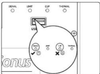
3.2 Onboard Performance Monitoring
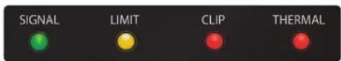
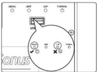
Performance Monitoring. These four LEDs display the performance status of the internal amplifier:
Signal. Illuminates green when a signal is present at the input.
Limit. Illuminates yellow when the internal limiter is engaged.
Clip. Illuminates red when the input signal reaches 0 dBFS. At this level, the signal will exhibit signs of clipping (distortion), and the analog-to-digital (ADC) converter (and therefore the amp) will be clipping.
Thermal. Illuminates red when the amplifier power supply or output stages exceed thermal limits. The amplifier will mute until the temperature drops below the thermal-limit threshold.
Power User Tip: Never run your input levels higher than the channel inputs can handle. If you overdrive the A/D converters, it will cause digital distortion (digital clipping), which sounds terrible.
It should be noted that additional performance monitoring is available in SL Room Control. Please see the SL Room Control Reference Manual.
3.2.1 A Note About the Limiter
All StudioLive AI-series loudspeakers provide reliable operation at high sound-pressure levels by incorporating an innovative new multi-band-limiting architecture. This system evaluates both the excursion and voicecoil temperature of every driver and uses that information to maximize the output of the loudspeaker while preserving the integrity of audio sources that span more than one band. This means that even when exceeding the threshold of the limiter, StudioLive AI-series loudspeakers continue to provide clean and powerful vocals, without the harsh edginess that is characteristic of conventional protection schemes. Because of this, you may not hear the limiter, even though the Limit light is illuminated.
3.3 Networking Connections and Controls
natural_image
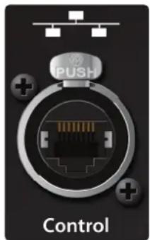
Close-up of a black electronic device with an Ethernet port and indicator lights, labeled 'Control' (no readable text or symbols beyond the label)Ethercon. Your StudioLive AI-series loudspeaker ships with a control option card installed. This option card houses an Ethercon connection to hardwire your speaker to a wireless router for use with SL Room Control. A standard RJ45 connector may be used but we recommend the protection provided by using the mating male Ethercon connector.
For more information on creating a wired LAN network, see the SL Room Control Reference Manual.
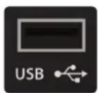
USB Connection and Wi-Fi Module. Your StudioLive AI-series loudspeaker features a USB connection for use with the included USB Wi-Fi module. This will allow you to wirelessly connect to a wireless network and remote control your StudioLive speaker.
For more information on connecting your StudioLive AI-series loudspeaker to an established wireless network, see the SL Room Control Reference Manual.
Power User Tip: While wireless networking is ideal for most mobile applications, it is highly recommended that a wired LAN network be employed for permanently installed systems or for large venues.
The USB connection can also be used for firmware updates when no network is available and for resetting your loudspeaker to its factory default state. For more information, see the SL Room Control Reference Manual.
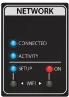
Network Status and Controls. These LEDs and controls provide information about network connectivity and allow you to configure your included wireless LAN adapter.
- Wi-Fi On Button and LED. To turn on Wi-Fi and activate wireless networking, press the recessed Wi-Fi button. The red On LED above the button will illuminate.
- Wi-Fi Setup Button and LED. The recessed Setup button is used to reset to the default wireless network name (StudioLive) and password (StudioLive). To reset, press and hold the Wi-Fi Setup Button for 3 seconds.
-
Network Status LEDs. Two LEDs indicate status of wired or wireless (Wi-Fi) network operation:
-
Connected. Illuminates blue when connected to either the Wi-Fi access point in the controlling device (a Mac, PC, or iPad) or the wired LAN. It will illuminate red when no network connection is present.
• Activity. Illuminates (blinking) as data packets are sent and received.
3.4 Power
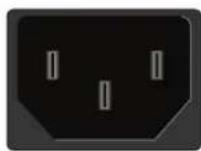
AC Line Connection. StudioLive-series loudspeakers have a universal power supply that accepts AC power input between 100 and 250V AC at 50/60 Hz. Each loudspeaker is supplied with a locking IEC cord appropriate for the country of sale.

WARNING: Do not remove the center grounding prong or use a ground-lift adapter, as this could result in electrical shock.
Power Switch. This is the On/Off switch for the StudioLive loudspeaker. Use the rear-panel power switch to turn the loudspeaker on (1) and off (0).

Power status is indicted by an LED on the front of the cabinet:
Off = power off
Blue = power on, manual mode
White = power on, remote mode
3 Hookup
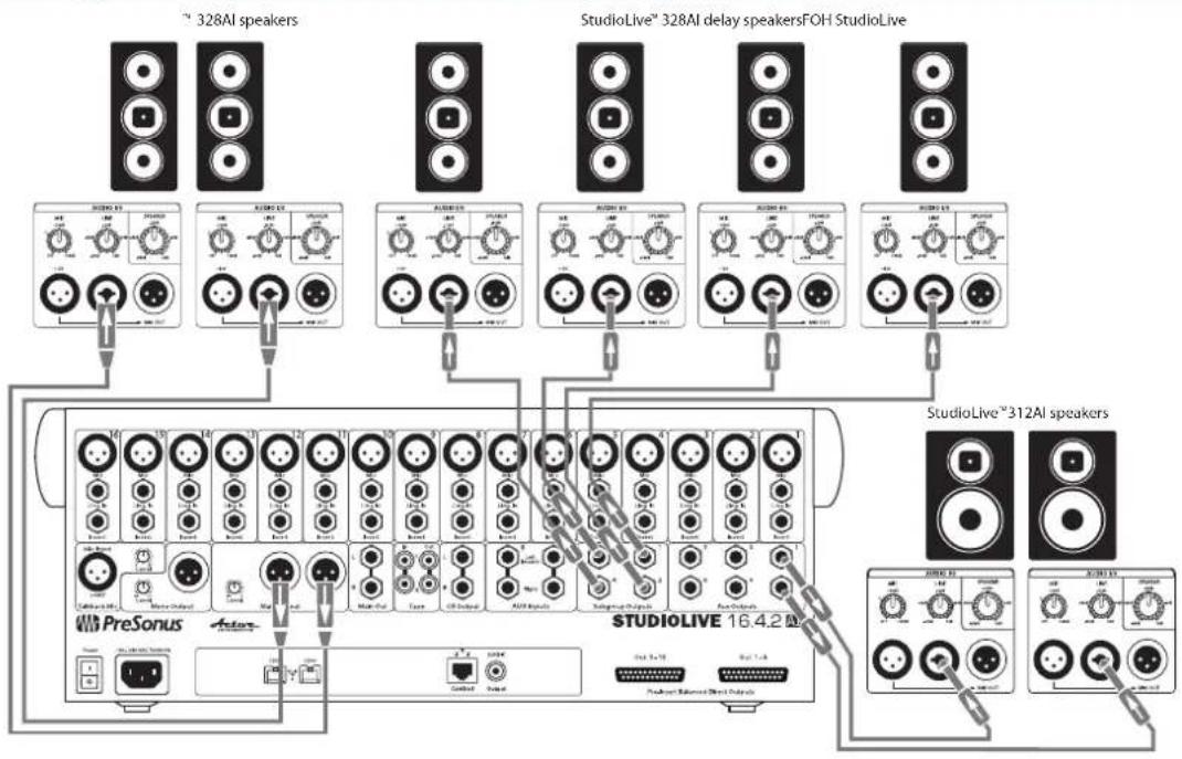
3.5 Basic Hookup Diagram
StudioLive AI-Series Loudspeaker
Owner's Manual
3.5 Basic Hookup Diagram
StudioLive™ 312AI speakers
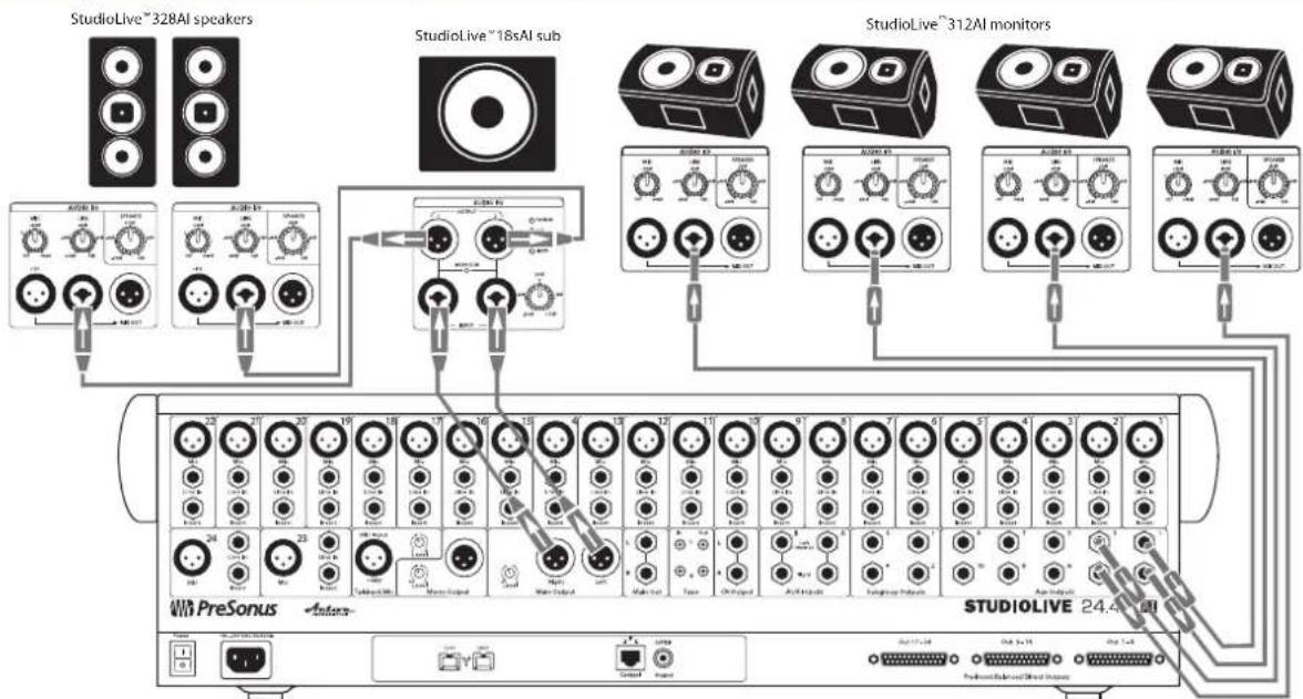
3.6 Typical Band Setup Diagram
flowchart
graph TD
    A["StudioLive™ 328AI speakers"] --> B["Audio/Video"]
    C["StudioLive™ 18sAI sub"] --> D["Audio/Video"]
    E["StudioLive™ 312AI monitors"] --> F["Audio/Video"]
    G["PreSonus"] --> H["Micro-Input"]
    H --> I["Main Input"]
    I --> J["Output"]
    K["STUDIO LIVE 24.4 AI"] --> L["Output"]
    style A fill:#f9f,stroke:#333
    style C fill:#f9f,stroke:#333
    style E fill:#f9f,stroke:#333
    style G fill:#f9f,stroke:#333
    style K fill:#f9f,stroke:#333
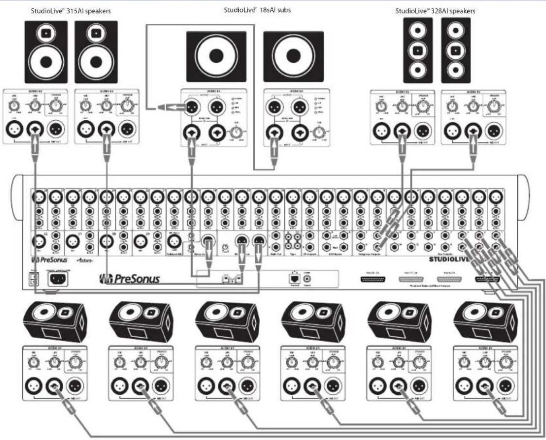
3.7 Typical Venue Setup Diagram
flowchart
graph TD
    subgraph_StudioLive_315AI_speakers["StudioLive^315AI speakers"]
        A1["ATMOLI"] --> B1["AVG"]
        A2["AVG"] --> B2["AVG"]
        A3["AVG"] --> B3["AVG"]
        A4["AVG"] --> B4["AVG"]
    end

    subgraph_StudioLive_18sAI_subs["StudioLive^18sAI subs"]
        B1 --> C1["AVG"]
        B2 --> C2["AVG"]
        B3 --> C3["AVG"]
        B4 --> C4["AVG"]
        B5["AVG"] --> C5["AVG"]
        B6["AVG"] --> C6["AVG"]
    end

    subgraph_StudioLive_328AI_speakers["StudioLive^328AI speakers"]
        C5 --> D5["AVG"]
        C6 --> D6["AVG"]
        C7["AVG"] --> D7["AVG"]
        C8["AVG"] --> D8["AVG"]
    end

    subgraph StudioLive_315AI_speakers
        E1["ATMOLI"] --> F1["AVG"]
        E2["AVG"] --> F2["AVG"]
        E3["AVG"] --> F3["AVG"]
        E4["AVG"] --> F4["AVG"]
        E5["AVG"] --> F5["AVG"]
    end

    subgraph StudioLive_18sAI_subs
        G1["ATMOLI"] --> H1["AVG"]
        G2["AVG"] --> H2["AVG"]
        G3["AVG"] --> H3["AVG"]
        G4["AVG"] --> H4["AVG"]
        G5["AVG"] --> H5["AVG"]
    end

    subgraph StudioLive_328AI_speakers
        I1["ATMOLI"] --> J1["AVG"]
        I2["AVG"] --> J2["AVG"]
        I3["AVG"] --> J3["AVG"]
        I4["AVG"] --> J4["AVG"]
    end

    subgraph StudioLive_315AI_speakers
        K1["ATMOLI"] --> L1["AVG"]
        K2["AVG"] --> L2["AVG"]
        K3["AVG"] --> L3["AVG"]
        K4["AVG"] --> L4["AVG"]
    end

    subgraph StudioLive_18sAI_subs
        M1["ATMOLI"] --> N1["AVG"]
        M2["AVG"] --> N2["AVG"]
        M3["AVG"] --> N3["AVG"]
        M4["AVG"] --> N4["AVG"]
    end

    subgraph StudioLive_328AI_speakers
        O1["ATMOLI"] --> P1["AVG"]
        O2["AVG"] --> P2["AVG"]
        O3["AVG"] --> P3["AVG"]
        O4["AVG"] --> P4["AVG"]
    end

    subgraph StudioLive_315AI_speakers
        Q1["ATMOLI"] --> R1["AVG"]
        Q2["AVG"] --> R2["AVG"]
        Q3["AVG"] --> R3["AVG"]
        Q4["AVG"] --> R4["AVG"]
    end

    subgraph StudioLive_18sAI_subs
        S1["ATMOLI"] --> T1["AVG"]
        S2["AVG"] --> T2["AVG"]
        S3["AVG"] --> T3["AVG"]
        S4["AVG"] --> T4["AVG"]
    end

    subgraph StudioLive_328AI_speakers
        U1["ATMOLI"] --> V1["AVG"]
        U2["AVG"] --> V2["AVG"]
        U3["AVG"] --> V3["AVG"]
    end
StudioLive™ 312AI monitors
3.8 Typical Corporate Conference Setup Diagram
flowchart
graph TD
    subgraph StudioLive™328AI |
| A["PreSonus"] --> B["StUDIO LIVE 16.4.2 M"]
    end
    subgraph StudioLive™312AI |
| B --> C["StUDIO LIVE 16.4.2 M"]
    end
    D["328AI speakers"] --> E["StUDIO Live™328AI delay speakersFOH"]
    E --> F["StUDIO Live"]
    style StudioLive™328AI fill:#f9f,stroke:#333
    style StudioLive™312AI fill:#bbf,stroke:#333
4 System Configuration
StudioLive AI-series full-range loudspeakers are designed to reproduce an input signal with extreme fidelity, maintaining near-flat frequency and phase response at all levels up to the threshold of clipping. However, the performance of any loudspeaker will be influenced by the acoustics of the space in which they operate. Difficult room acoustics, combined with improper loudspeaker placement, can interfere with achieving the fidelity of which your StudioLive AI-series loudspeakers are capable. To help you get the most out of your system, this section has been included to guide you around some of the pitfalls when configuring a PA system.
4.1 Recognizing Problem Rooms
In most live environments, the room is rarely designed to maximize the listening experience. More often then not, money is spent on aesthetic appeal rather than acoustic treatment. For large-scale tour productions, venues are often sports arenas that have been designed to maximize crowd noise. Smaller music venues are often chosen for location or architectural aesthetics, rather than music reproduction. While an empty warehouse or old wine cellar might make a great environment to hang out in, it's necessary to recognize and correct what that space does to the sound system in order to optimize the PA's performance in the venue.
In general, the following physical features of a room can affect a sound system's performance:
•Room size
- Construction
•Reflectivity
The size of the room directly impacts how well certain frequencies will be reproduced. For example, if you measure a room diagonally, you will discover how well that room will be able to sustain low frequencies. This may seem odd until you think about the physical size of audio waves at various frequencies. For example, a 50 Hz wave is about 22.6 feet long. (To calculate how big an audio wave is, divide the speed of sound—1,130 ft./second—by the frequency. For a 50 Hz wave, 1,130/50 = 22.6 ft.) So a room that is 45 feet on the diagonal is going to regenerate low frequencies more effectively than a room that is 15 feet on the diagonal.
When a room's width or length correlates directly to the size of a waveform at a specific frequency, a standing wave can occur where the initial sound and the reflected sound begin to reinforce each other. Let's say we have a long, narrow room where the distance from one side to the other is 22.6 feet. When a 50Hz wave bounces off the wall, the reflective wave travels right back along the same path and bounces off the other wall and cycle repeats. In a room such as this, 50Hz reproduces very well—maybe too well. So any mix will have a heavier low end.
In addition, low-frequency waves are powerful enough to cause the walls, ceiling, and even the floor to flex and move. This is called “diaphragmatic action,” and it dissipates energy and strips away the low-end definition. So if you’re in an old cotton mill, and the walls and floor are made of thick concrete that don’t vibrate much, the bass response is going to be much more powerful than if you’ve set up a show in an old warehouse where the walls are made of barge board and tin.
4.1.1 Vertical Coverage
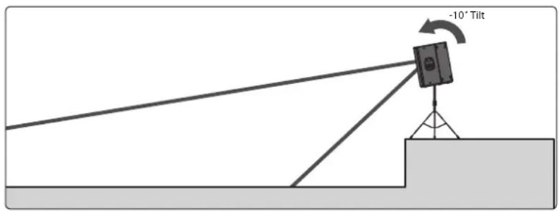
It is important to keep in mind that vertical coverage is just as important as horizontal coverage. If you are using a ground-stack approach with pole mounts, make sure your coverage matches the listening plane. Suspension of speakers will provide even further control.
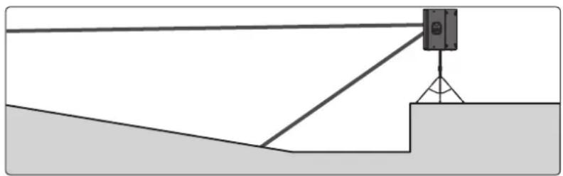
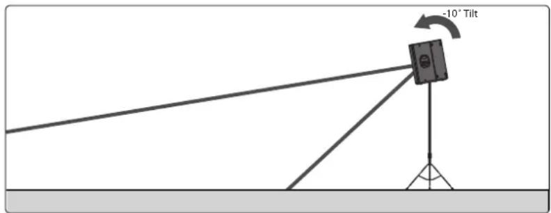
Each StudioLive AI-series full-range loudspeaker features dual-position pole mounts. Using the 10^ downward tilt mount will focus the loudspeaker's energy onto the audience and avoid destructive reflections. This is ideal for situations where the loudspeaker is mounted atop a tripod stand and placed on a stage, or where the pole-mounted loudspeaker is on the floor and the coverage area is relatively shallow (conference, coffee house, etc.).
Flat Floor with Stage
Elevated Floor
natural_image
Diagram of a surveying setup with a camera mounted on a tripod, no text or symbols presentNo Stage, Flat Floor
4.1.2 Wall and Corner Loading
Very low frequencies are not directional, so they radiate out of the sides and back of the loudspeaker, as well as out of the front. If you place a loudspeaker against a wall, the rear sound propagates back into the room. This can increase output of bass frequencies as much as 6 dB, and as much as 12 dB if you put the loudspeaker in a corner.
In order to have the most control over your sound, it's best to always start with the flattest response, so you normally should avoid wall and corner placement. On the other hand, if you need some extra bass boost, this technique may be worth a try. It is important to be aware of what's happening and be prepared to take advantage of it or compensate for it.
Power User Tip: Because a floor monitor placed on the stage is unavoidably subject to half-space loading, the Monitor DSP contour in your StudioLive AI-series full-range loudspeaker is specifically designed to compensate for bass buildup and maintain a tight mid-bass response.
4.1.3 Maintain a High Direct-to-Reverberant Ratio
Another way a room interacts with sound waves is through reflectivity. Like most room anomalies, reflections can be good and bad. Consider the effect of a cathedral's reflections on a choir or a piano. This type of reverberation (reverb) is quite desirable. But not all reverb is good reverb. Reflections can also cause comb filtering. For example, if a speaker is placed near a reflective surface (such as a concrete wall), the direct sound coming from the speaker and the reflected sound coming from the wall can arrive at the listener's ears out of phase with each other, causing cancellation and reinforcement. If they're 180 degrees out of phase with respect to each other, they will cancel each other out.
If you are using your loudspeakers in a reverberant environment, position them so that as much sound as possible is focused on the audience area and steered away from reflective surfaces. StudioLive AI-series full-range loudspeakers have a nominal 90-degree horizontal and 60-degree vertical coverage pattern. When you do your placement and positioning, it's a good idea take some time to do a "walk around" of your loudspeakers, playing either pink noise or program material, so you get a feel for how the sounds are translating into the room.
4.2 Delay Systems
In most situations, a PA system relies on two main speaker systems positioned at the front of the room to reproduce audio for the entire performance space. As a result, the level of the system is considerably louder at the front line then it is at mix position.
With a point source, horn-loaded loudspeaker (such as a single, powered loudspeaker), sound intensity is lost at a rate of -6 dB per doubling of distance. This is true regardless of tuning, amplification, power rating, or any other speaker specifications. So if your signal level is 106 dB SPL at 1 foot, at 8 feet away it's down by 18 dB!
Here's a simple chart that illustrates the math:
| DISTANCE dB SPL DISTANCE dB SPL | ||||
| 1 ft. 106 dB | 8 ft. 88 dB | |||
| 2 ft. 100 dB | 16 ft. | 82 dB | ||
| 4 ft. | 94 dB 32 ft. | 76 dB | ||
In situations where sound must be reproduced outside of the main system's optimum range, well-placed delay systems offer support by extending the intelligible range of the PA. Rather than relying on a pair of front-of-house speakers to fill the entire room, you can create listening zones throughout the room so that your front-of-house system only needs to be loud enough to cover the front of the room. This allows you to lower the level, give the front-row listeners' ears a break, and get better fidelity from your speakers.
However, it's not as easy as just bringing an extra pair of speakers. Since electricity travels much faster than sound, listeners in the rear of the room are likely to hear the sound coming from the nearest set of speakers before they hear the sound from stage, which can dampen the attack and intelligibility of the sound and create an unpleasant phasing effect.
To compensate, you need to delay the signal going to the additional speakers. For example, it takes about 55 ms for sound to travel 50 feet. So if you put your speakers 50 feet back, you need to delay the signal by that much.
Fortunately, with StudioLive AI-series loudspeakers and SL Room Control, you can delay each speaker by up to 300 ms. All you need is a reasonably accurate measurement of the distance between your main speakers and delays.
4.2.1 Delay Basics
Delay speakers allow you to run the main speakers at a lower volume, as they relieve the mains of handling high- and mid-frequency content for part of the space. As a speaker is pushed harder, the edges of its frequency response begin to distort, so by easing the demands on the mains, delay systems increase fidelity sonically, as well as mechanically. This also means that the front row doesn't need to be blasted just so the people at the back can hear the show.
The goal of distributed sound is to extend the intelligible range of the system, without killing the front of the crowd with excessive level. As noted earlier, sound travels much slower than electricity, so the audio coming out of the delay system will arrive to the listeners before the audio coming out of the main system. Without proper alignment, the multiple arrival times create confusion to the listener and sonic definition is lost. Speech and beat transients become less intelligible. In large venues, this can actually create a flam or echo effect. By delaying the audio going to side and rear fills, you can create a cohesive listening environment for the entire audience.
It should be noted that frequencies in the sub-bass range of a delay system do not require distribution. In fact, a delay system's highpass filter should be rolled up as high as 300 to 400Hz to avoid sound going back toward the stage as low frequencies become omnidirectional.
When placing delay systems, the main goal is to maintain intelligibility of the PA, especially in the vocal consonant range (2 to 4 kHz). However, this goal is achieved by overcoming different obstacles depending on whether you are indoors or outdoors. In both situations, the delay system should be set where the main system's intelligibility falls apart. As with the main system, the placement of the delay systems will determine how successfully you are able to achieve these goals.
Inside. Indoors, you are trying to overcome the direct-to-reverberant reflections. The location of the delay system is dependent on the critical listening area (typically just behind front-of-house). Your goal is to find where the direct signal-to-reverberation ratio has reached about 50/50. At this point, the reflections in the room are at an equal level to the direct sound of the PA, and vocal intelligibility is lost. Listen for a lack of intelligibility in the vocals and find the point at which the drums and rhythm section don't feel tight.
A great way to find the best position for your delay speakers is to set up and tune your main system and play audio through it. Play something similar to what you will be mixing later. Set the level so that it is comfortable from the front row. Walk backward away from the main system until you notice a lack of clarity. This is the beginning of the space that will need delay-system coverage.
Outside. Outdoors, you are trying to maintain level as the noise floor of the crowd begins to be at equal level to the PA in the intelligibility range. When working outside, the delay system is used to overcome outdoor noise, including (but not limited to) crowd murmur, concessions, generators, tractors, babies, etc. At this point, the main system needs more support in order to deliver the same perceived loudness as you get further from the source.
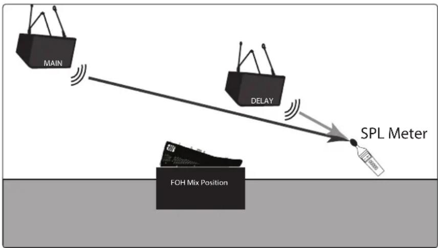
Once you have positioned and delayed your satellite system, use an SPL meter to match the output of the main and delay systems at the measurement point. If you are standing 20 feet from the left side of the main system and 30 feet from the left side of the delay system, and if the output of the main system is 85 dB, the output of the delay system should also be 85 dB.
4.2.2 Sub Alignment
The 18sAI subwoofer has been designed and customized for use with the full-range AI-series loudspeakers. It features three delay presets to guarantee that your 4-way system stays in alignment:
natural_image
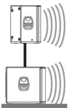
Diagram of two connected devices with sound waves, no text or symbols present0m1m
natural_image
Diagram of a smart speaker setup with two speakers and a stand, showing signal waves (no text or labels)OM. Select this setting when the full-range system is directly over the subwoofer (i.e., mounted atop using the SP1BK sub-pole accessory). No delay is added to the subwoofer amplifier output.
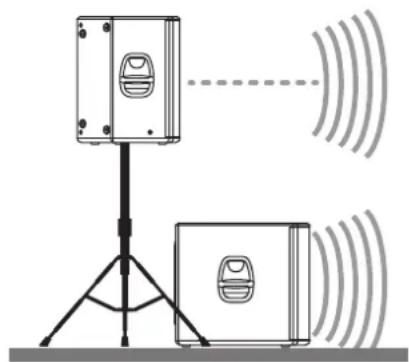
1M. Select this setting when the subwoofer is about one meter from the full-range loudspeaker—a typical distance when the loudspeaker is on an adjacent tripod stand. A delay of about 2.9 ms is introduced to the signal that is output through the subwoofer amplifier.
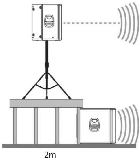
2M. Select this setting when the subwoofer is about two meters from the full-range loudspeaker—typical when the full-range system is on the stage and the subwoofer is on the floor. A delay of about 5.9 ms is introduced to the signal that is output through the subwoofer amplifier.
The Alignment delay setting compensates for the cancellation or reinforcement of low frequencies when the same frequencies are reproduced by two sound sources that are set some distance apart. Low frequencies in the crossover region between full-range and subwoofer have wavelengths that are several feet long—the wavelength of a 150 Hz wave is about 7.5 ft—which means that reinforcement and cancellation will occur as the waves interact in the room. The Alignment delay provides compensation for this effect when the loudspeaker is about the same distance away from, or in front of, the subwoofer, as specified in the setting. As room acoustics will influence effectiveness, we recommend listening tests using the different Alignment settings, in conjunction with alternate Polarity settings, to determine the best results.
If you are aligning for a custom installation, or the subs must be located some distance from the main speakers, you will need to do some calculating.
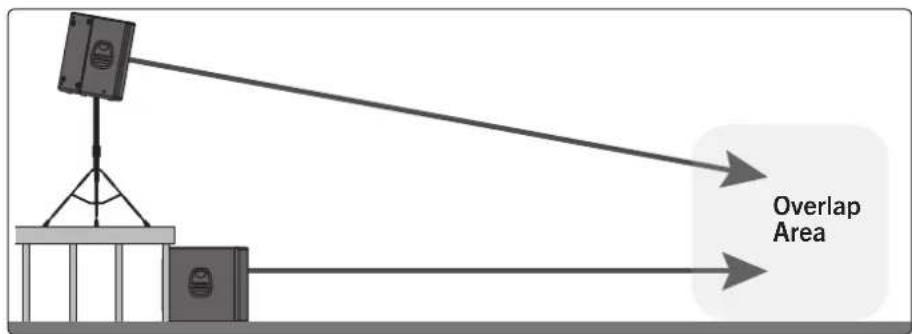
flowchart
graph TD
    A["Base Station"] --> B["Signal"]
    B --> C["Overlap Area"]
    C --> D["Output"]
Find the spot in the room where coverage from the main speakers and the subwoofers overlap. Measure the distance from the overlap area to each speaker location. Subtract the smaller distance from the larger. Divide that number by 1,100 and apply that delay value to the speaker that is closest. Keep in mind that the overlap area may be behind FOH.
4.2.3 Real-World Delay System Example
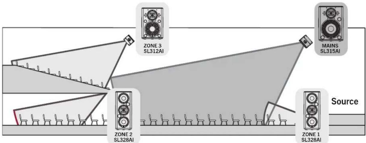
flowchart
graph TD
    Source --> ZONE1["ZONE 1 SL328AI"]
    Source --> ZONE2["ZONE 2 SL328AI"]
    Source --> ZONE3["ZONE 3 SL312AI"]
    MAINS["MAINS SL315AI"] --> ZONE3
    MAINS --> ZONE2
    MAINS --> ZONE1
The goal in a complicated system with loudspeakers distributed throughout the venue is to delay each satellite system to its counterpart in the main system (e.g., the left front fill to the left FOH loudspeaker).
- Delay the main system relative to the source on stage. On small stages where the guitar amp and drum kit can be clearly heard above the FOH loudspeaker system, delaying the main system can "move up" the backline so that it aligns with these instruments and decreases blurring in the mix. This will tighten the overall mix and give it more punch.
- Delay the front fills relative to the main system by delaying each side of the system independently (e.g., delay the left front fill to the left FOH loudspeaker).
- Delay subwoofers relative to the main system. How you do this will depend on how your subwoofer system is positioned and configured. In general, you will want to delay each subwoofer relative to the full-range loudspeaker closest to it.
- Delay down-fill speakers (upper and under balcony) relative to the main system, again delaying each side of the system independently.
4.2.4 System Configuration Suggestions
The following subsections will demonstrate some system configurations for common rooms. The size and shape of your room and the application for which it will be used determine, to a large extent, how many speakers you will need and where they should be placed. In every situation, keep in mind two important design factors: your loudspeaker's coverage pattern and half-space loading.
Every full-range StudioLive AI loudspeaker offers a 90° horizontal x 60° vertical coverage pattern. Be sure to pay close attention to these angles when using your speakers. Rotating the cabinet changes the horizontal and vertical coverage.
When configured for stereo use, make sure the cabinets are not placed too wide for the room or too far back into the corners. Too wide of a placement will direct too much energy onto the walls and can potentially add destructive interference to the room. Adjust the left and right speakers, as well as the toe-in angle, to produce the best stereo image. If a room is very narrow, a mono cluster might be a better choice than stereo.
Wherever you place your loudspeakers, you should be aware of half-space loading. Half-space loading occurs when a speaker comes in close contact with, or touches, a hard surface like a floor or wall. As its name indicates, this type of summation happens when the circular radiation of the speaker is blocked by a hard surface and forced to radiate in a crescent shape. Depending on the proximity and position, there may be a boost in low-frequency energy. Testing your speaker placement and doing some critical-listening tests will
help determine the best final location for your loudspeaker system.
If your speakers are sitting on the floor, you can expect a certain amount of half-space loading. If you are using your speakers as floor wedges, you might want to experiment with using the High Pass Filter to reduce low energy. In some cases, this might improve intelligibility. Using the Floor Monitor DSP contour will also help you get the best use out of your StudioLive AI loudspeakers in this position.
4.2.5 Stereo System
natural_image
Diagram of a symmetrical geometric structure with curved and straight lines, containing grid-like patterns (no text or symbols)A stereo system allows panning and adds depth to the acoustic image. This is good for speech reinforcement and greatly enhances live or prerecorded music. Locate speakers to give the best horizontal coverage. Ensure that the listeners are well covered by the pattern.
4.2.6 Mono Cluster with Down Fill
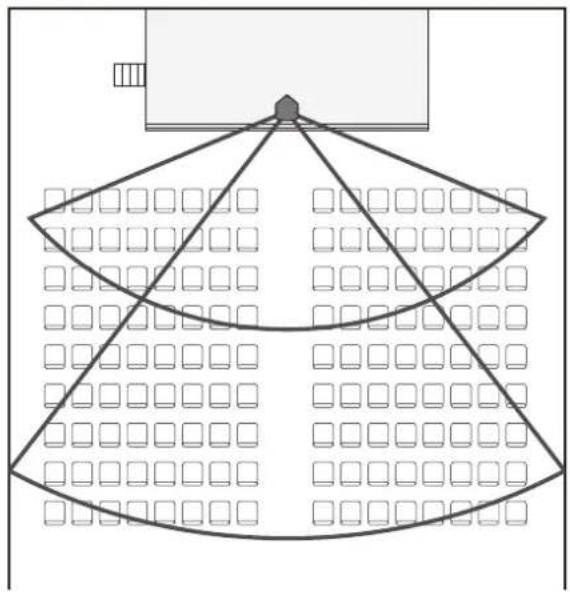
natural_image
Diagram of a geometric structure with a central triangular frame and surrounding grid pattern (no text or symbols)Center or mono systems can provide a simple, economical solution for venues where speech intelligibility is the priority, rather than music. As with a stereo system, make sure the coverage pattern of the speaker focuses the energy on the audience.
This graphic actually shows two speakers. The upper speaker is for throwing to the back of the room, and the lower speaker covers the space in the front of the room, closest to the stage.
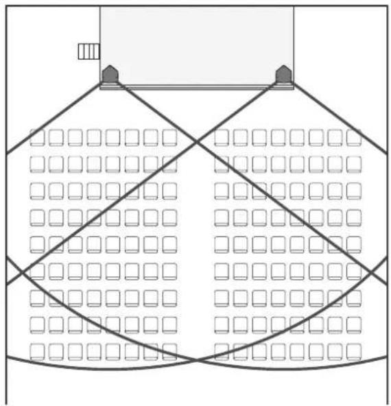
4.2.7 LCR Systems
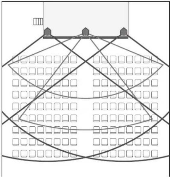
natural_image
Diagram of a stadium seating layout with grid patterns and support structures (no text or labels)An LCR system is a stereo system with a center speaker added. This configuration allows panning and adds depth to the acoustic image. This type of system will provide more control than a basic stereo system and is ideal in situations where music and speech intelligibility are equally important.
4.2.8 Monitor Systems
adoring audience adoring audience
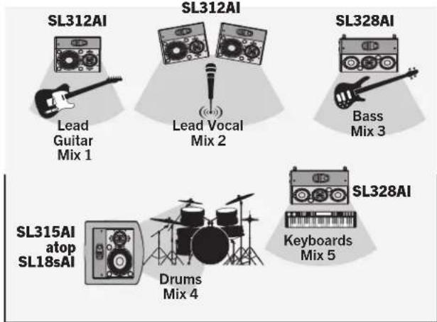
Above is a typical stage-monitor layout for a five-piece band. For musicians (such as a vocalist) who don't require a lot of low-frequency energy in their floor wedge, we suggest using a 312AI. For musicians that need a little more bass, the 328AI is preferable. The drum monitor in this example is a full-range, 4-way system (a 315AI atop an 18sAI). This can be configured with or without the highpass filter engaged on the 315AI, depending on how much 100 Hz overlap the drummer prefers. For smaller stages, a 315AI atop a low tripod or in the horizontal floor-wedge position will be more than adequate.
4.3 Rigging and Safety
This section has been created as a reference for safe rigging and mounting practices. It is not an installation tutorial. PreSonus StudioLive AI-Series loudspeakers are professional products and are not intended for consumer use. Installation of PreSonus StudioLive AI loudspeakers should only be undertaken by a qualified systems integrator or a professional rigger. Every audio project is unique and a licensed and insured professional should be consulted to guarantee the safety and performance of the installed system. The installer must have a complete understanding of the design intent as well as knowledge of safe installation techniques to create a successful project.
Understanding safe rigging and mounting practices will provide these benefits:
• Proper coverage of listening area with accurate speaker placement.
- Best installation methods will be utilized with regard to safety, performance, aesthetics, and cost.
- Minimal wasted time during installation.
4.3.1 Safety is the Priority
WARNING: Failure to observe the following safety precautions may result in severe injury or death. Installations such as described in this guide should only be attempted by a trained professional.
- Inspect all the components associated with the project for damage before assembly. Any suspect parts should not be used, and the component manufacturer should be contacted to arrange for replacement parts.
- Read all instructions shipped with selected speaker or rigging products. Make sure you fully understand all components.
•Always make sure that the structure the loudspeaker is to be suspended from has been approved by the building or structural engineer and will support the weight of all the components of the speaker system including speakers, speaker cable, wire rope, etc. - Make sure all installation crew members are trained for loudspeaker rigging and mounting and are in compliance with applicable local laws. Local government offices can help with this information.
- Make sure that all relevant health and safety regulations are known and followed by the installation crew.
- Suspended installations must be completed or supervised by a certified rigger.
- The system should be designed so that it is a static suspension. There should be no dynamic or shock loading.
- Personal protective equipment (hardhats, steel-toed footwear, safety glasses, etc.) should be worn at all times by the installation crew.
- If called for in the design, make sure all installation personnel are trained to work at height and have certifications for scissor lifts, theatrical hoists, etc.
- Make sure all lifting equipment (slings, span-sets, deck chain, scaffolding, etc.) is in good working order. Thoroughly inspect all components prior to use.
- Keep a tidy workplace. Do not leave tools, rigging items, etc., on top of loudspeakers during installation. Loose items can fall and cause injury.
- Never leave the system unattended during the installation process. Make sure that the workspace is isolated from public access. No one should be allowed to pass beneath the loudspeakers during installation.
- Do not suspend any other components or loudspeakers from PreSonus StudioLive AI loudspeakers.
- If secondary steel safeties are required, they should be installed once the entire system is at operating height and before public access is allowed.
4.3.2 Ground Stacking
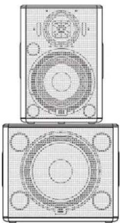
natural_image
Technical line drawing of a two-tiered speaker or audio device with circular and rectangular components (no text or symbols)StudioLive AI-series full-range loudspeakers have four nonskid rubber feet on the bottom for upright front-of-house use and four nonskid rubber feet on one side for stage-monitor applications.
If your application is primarily portable, PreSonus loudspeakers can be easily ground stacked and configured for a variety of venues. When ground stacking, make sure all speakers are securely anchored to the floor using load straps or other anchors. Rubber mats can also be utilized between cabinets to prevent boxes from "walking." This is particularly important if the speakers are accessible to the public.
Check that the surface the speakers are to be stacked on is level, even, and has sufficient structural integrity to support the speakers. If ground stacking on a portable stage, make sure you know what is directly below the speaker stack.
WARNING: Placement on improper or unstable surfaces could cause the loudspeaker to topple, which could result in serious injury or death.
4.3.3 Pole Mount
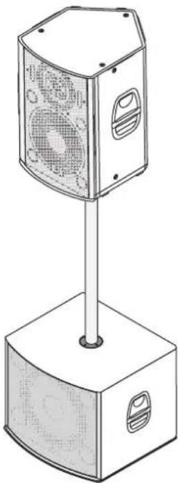
natural_image
Line drawing of a multi-tiered electronic device with fan and vent slots, mounted on a base (no text or symbols)All full-range StudioLive loudspeakers are equipped with 35 mm pole socket that allows the speaker to be mounted on a speaker stand or on a pole over an 18sAI subwoofer. This pole socket allows for straight 90° vertical mounting or for tilting the full-range loudspeaker down 10° while on a pole.
When using a tripod speaker stand, extend the legs to provide the most stable support to the speaker so that it cannot be tipped over. It is highly recommended that tripod stands be placed away from foot traffic. If the stands are to be used outdoors, theatrical sand bags may be placed on the legs to provide some protection against wind load.
StudioLive AI-series full-range loudspeakers can be mounted on top of a StudioLive 18sAI subwoofer using the optional SP1BK threaded subwoofer pole. This 31.5-inch pole is designed to secure the 18sAI subwoofer and has been pull- and tilt-tested for safety with all three full-range StudioLive AI-series loudspeakers.
WARNING: Do not substitute a longer pole from a third-party supplier. Use of a longer pole than specified could cause instability, which in turn could result in serious injury or death.
WARNING: StudioLive AI-series loudspeakers weigh a minimum of 51 lbs (23.1 kg). Use proper lifting techniques and safety precautions when mounting an AI-series loudspeaker on a SP1BK subwoofer pole or speaker stand. When mounting atop a speaker stand, verify that it is rated to support the weight of your StudioLive AI-series loudspeaker. The weight of each model can be found in Section 5.1.
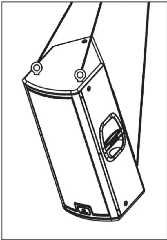
4.3.4 Suspending the Loudspeaker
A minimum of three suspension points must be used per speaker to safely suspend StudioLive AI loudspeakers. Two wires fixed symmetrically to the front of the cabinet to hold the weight and one wire attached to the back for tilt will satisfy this requirement. Select the strongest overhead structure available for the two front points and, if possible, two independent points to allow one to act as a backup. Attach the two front points first and then adjust tilt angle to ensure the load is safely suspended during installation. If additional pan or height adjustment is needed, make sure to follow this rule as well. Do not suspend any other items from PreSonus StudioLive AI loudspeakers.
SUPPORTED: Two front rigging points plus a pull-back
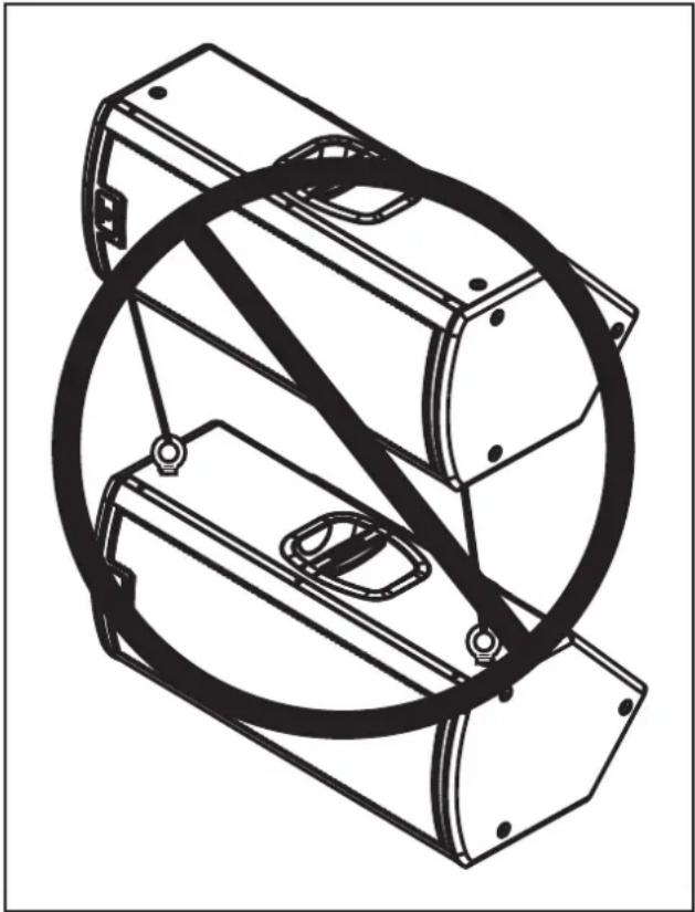
natural_image
Technical line drawing of a mechanical device with mounting holes and internal components (no text or symbols)NOT SUPPORTED: One StudioLive Loudspeaker attached to another
natural_image
Technical line drawing of a mechanical assembly with intersecting circular components (no text or symbols)PreSonus offers an M10 Kit that includes four (4) forged-shoulder steel M10 eyebolts. This kit is to be used with the 312Al, 315Al, and 328Al M10 suspension points. These bolts are specifically designed for safe suspension of PreSonus StudioLive AI loudspeakers and must not be substituted. These eyebolts are not a common hardware store item. Please read all included information. A minimum of three (3) eyebolts per cabinet must be used for safe suspension.
When using the M10-AI Kit, please remember that the eyebolt strength rating will vary with the pull angle. It is extremely important to observe appropriate pull angles when suspending any loudspeaker with eyebolts. Suspending an object with eyebolt should always be done in a way that ensures the resultant forces are within the allowed pull angles.
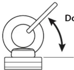
Do not use at 45° or less
4.3.4 Precautions
StudioLive AI-series loudspeakers, like all electrical devices, must be protected from liquids or excessive moisture. They are not designed for outdoor use during inclement weather. If you are using your StudioLive AI-series loudspeakers outside when rain or other wet weather occurs, immediately power down your loudspeakers and protect the cabinets with waterproof coverings.
The amplifiers in StudioLive AI-series loudspeakers are convection cooled via the rear-panel heatsink. Free airflow must be maintained around and behind the heatsink, with a minimum clearance of six inches behind the cabinet. Make certain the heatsink is kept clear of any adjacent materials, such as stage curtains, that could impede airflow.
5 Technical Information
5.1 Specifications
| SLS312AI SLS315AI SLS328AI SLS18sAI | ||||
| Acoustic Performance | ||||
| Configuration | 3-Way, Tri-amplified Loudspeaker System | 3-Way, Tri-amplified Loudspeaker System | 3-Way, Quad-amplified Loudspeaker System | Powered Subwoofer, Ported |
| Frequency Response (-10 dB) | 50 Hz - 23 kHz 46 Hz - 23 kHz 54 Hz - 23 kHz 29 Hz - 141 Hz | |||
| Frequency Response (-6 dB) | 56 Hz - 22 kHz 52 Hz - 22 kHz 59 Hz - 22 kHz 32 Hz - 110 Hz | |||
| Nominal Coverage (-6 dB) | 90 x 60 90 x 60 90 x 60 n/a | |||
| Maximum Peak SPL | 131 dB 131 dB 133 dB 135 dB | |||
| Crossover Frequency | LF: (overlapped) 100 Hz - 1 kHz, HF: 1.8 kHz | LF: (overlapped) 100 Hz - 1 kHz, HF: 1.8 kHz | 1.7 kHz n/a | |
| Directivity Index (DI) | 10 dB, >500 Hz 10 dB, >420 Hz 10 dB, >460 Hz | n/a | ||
| Directivity Factor (Q) | 10.0, >500 Hz | 10.0, >420 Hz | 10.0, >460 Hz | n/a |
| Transducer | ||||
| LF Transducer | 12" Ferrite | 15" Ferrite | 2 x 8" Ferrite 18" Ferrite | |
| Voice Coil Diameter | n/a | n/a | n/a | 4" |
| MF Transducer | 8" CoActualTM | 8" CoActualTM | 8" CoActualTM | n/a |
| HF Transducer | 1.75" Compression Driver | 1.75" Compression Driver | 1.75" Compression Driver | n/a |
| Amplifier | ||||
| Type | Class D Class D Class D Class D | |||
| Total Power Output | 2000W (Total Power without Protection Algorithms & Limiter enabled) | 2000W (Total Power without Protection Algorithms & Limiter enabled) | 2000W (Total Power without Protection Algorithms & Limiter enabled) | 1000W (Total Power without Protection Algorithms & Limiter enabled) |
| LF Power | 2 x 500W Bridged | 2 x 500W Bridged | 2 x 500W | 2 x 500W Bridged |
| MF Power | 500W | 500W | 500W | n/a |
| HF Power | 500W | 500W | 500W | n/a |
| Rated THD | < 0.05% (20 Hz - 20 kHz) | < 0.05% (20 Hz - 20 kHz) | < 0.05% (20 Hz - 20 kHz) | < 0.05% (20 Hz - 20 kHz) |
| Dynamic Range | 119 dB (A-weighted) | 119 dB (A-weighted) | 119 dB (A-weighted) | 119 dB (A-weighted) |
| Bandwidth | 20 Hz - 20 kHz 20 Hz - 20 kHz 20 Hz - 20 kHz | |||
| Cooling | Free Air Convection | Free Air Convection | Free Air Convection | Free Air Convection |
| Connections & Controls | ||||
| Input Channels | 1 Mic, 1 Line | 1 Mic, 1 Line | 1 Mic, 1 Line | 2 Line |
| Input Connector Types | 1 XLR(F), 1 Combo | 1 XLR(F), 1 Combo | 1 XLR(F), 1 Combo | 2 Combo |
| Phantom Power | 15VDC (CH1 only) | 15VDC (CH1 only) | 15VDC (CH1 only) | n/a |
| Mic Input Impedance | 1 kΩ | 1 kΩ | 1 kΩ | n/a |
| Line Input Impedance | 10 kΩ | 10 kΩ | 10 kΩ | 10 kΩ |
| Maximum Input | +22 dBu | +22 dBu | +22 dBu | +22 dBu |
| Output Connector | 1 XLR(M) - Mix Out | 1 XLR(M) - Mix Out | 1 XLR(M) - Mix Out | 2 XLR (M) - Thruput |
| Controls | Mic Level (Variable: Off to +48 dB), Line Attenuation (Variable: -24 dB to 0 dB), Speaker Attenuation (Variable: -24 dB to 0 dB) | Mic Level (Variable: Off to +48 dB), Line Attenuation (Variable: -24 dB to 0 dB), Speaker Attenuation (Variable: -24 dB to 0 dB) | Mic Level (Variable: Off to +48 dB), Line Attenuation (Variable: -24 dB to 0 dB), Speaker Attenuation (Variable: -24 dB to 0 dB) | Speaker Level (Variable -12 dB to +12 dB), Mono Sum |
| Indicators | DSP Preset, HPF On/Off, Network Activity, WiFi Setup, WiFi On, Signal, Limit, Clip, Thermal | DSP Preset, HPF On/Off, Network Activity, WiFi Setup, WiFi On, Signal, Limit, Clip, Thermal | DSP Preset, HPF On/Off, Network Activity, WiFi Setup, WiFi On, Signal, Limit, Clip, Thermal | DSP Preset, Delay Preset, Polarity Invert, Network Connected, Network Activity, WiFi Setup, WiFi On, Signal, Limit, Clip, Thermal |
| Continued on the following page... | ||||
| Continued from the previous page... | ||||
| SLS312AI SLS315 AI SLS328AI SLS18sAI | ||||
| DSP | ||||
| Contour Presets | Normal, LBR Source, Floor Monitor | Normal, LBR Source, Floor Monitor | Normal, LBR Source, Floor Monitor | Normal, Extended LF |
| HPF | 100 Hz 4th Order Linkwitz Riley | 100 Hz 4th Order Linkwitz Riley | 100 Hz 4th Order Linkwitz Riley | n/a |
| Polarity | n/a n/a n/a Normal or Reverse | |||
| Delay Presets | n/a n/a n/a 0M, 1M, 2M | |||
| Bit Depth | 24-bit 24-bit 24-bit 24-bit | |||
| Sample Rate | 96 kHz 96 kHz 96 kHz 96 kHz | |||
| Enclosure Material | 15 mm Baltic Birch 15 mm Baltic Birch 15 mm Baltic Birch 15 mm Baltic Birch | |||
| Finish | Chemline Chemline Chemline Chemline | |||
| Grille | Powder-coated Steel Powder-coated Steel Powder-coated Steel Powder-coated Steel | |||
| Dimensions (H x D x W) | 24.8" x 19.5" x 16.4" (630 x 496 x 417 mm) | 27.9" x 21.5" x 18.6" (709 x 547 x 473 mm) | 30.1" x 15.7" x 13.3" (765 x 399 x 338mm) | 23" x 24" x 26" (585 x 610 x 661 mm) |
| Unit Weight | 62 lbs (28.12 kg) 71 lbs (32.2 kg) 51 lbs (23.13 kg) 94 lbs (42.64 kg) | |||
| Handles | One on each side | One on each side | One on each side | One on each side |
| Monitor Angle | 50° | 50° | 50° | 50° |
| Safety | ||||
| Amplifier Protection | Over-Current, DC, Over/Under-Voltage, Over-temperature, High Frequency | Over-Current, DC, Over/Under-Voltage, Over-temperature, High Frequency | Over-Current, DC, Over/Under-Voltage, Over-temperature, High Frequency | Over-Current, DC, Over/Under-Voltage, Over-temperature, High Frequency |
| Transducer Protections | 4-ch. Multi-Threat Limiter | 4-ch. Multi-Threat Limiter | 4-ch. Multi-Threat Limiter | 4-ch. Multi-Threat Limiter |
| AC | ||||
| AC Power Input | 100-230V~, 50-60 Hz | 100-230V~, 50-60 Hz | 100-230V~, 50-60 Hz | 100-230V~, 50-60 Hz |
| AC Power Consumption (1/8 Power) | 250W | 250W | 250W | 150W |
| Suspension/Mounting Rigging Points | 12 M10 | 12 M10 | 12 M10 | n/a |
| Mounting | 35 mm, 2-Position | 35 mm, 2-Position | 35 mm, 2-Position | n/a |
| Accessories/Replacement Parts | ||||
| USB Wireless | WF-150 | WF-150 | WF-150 | WF-150 |
| M10 Kit | M10Al-Kit | M10Al-Kit | M10Al-Kit n/a | |
| Protective Cover | SLS312Al-Cover | SLS315Al-Cover | SLS328-Cover | SLS18sAl-Cover |
| Sub Pole | SP1BK | SP1BK | SP1BK | SP1BK |
| Sub Dolly | n/a n/a n/a | D18s | ||
| Replacement Parts | 355-NRG-COAX-8: 8" Coaxial Driver355-NRG-LO-FREQ-12: 12" Low-Frequency Driver600-NRG0181: SLS312Al Grill600-NRG0153: Handle Assembly | 355-NRG-COAX-8: 8" Coaxial Driver355-NRG-LO-FREQ-15: 15" Low-Frequency Driver600-NRG0182: SLS315Al Grill600-NRG0153: Handle Assembly | 355-NRG-COAX-8: 8" Coaxial Driver355-NRG-LO-FREQ-8: 8" Low-Frequency Driver600-NRG0176: SLS328Al Grill600-NRG0153: Handle Assembly600-NRG0205: Sliding Foot Bracket | —355-NRG-LO-FREQ-18: 18" Low-Frequency Driver600-NRG0183: SLS18sAl Grille600-NRG0153: Handle Assembly |
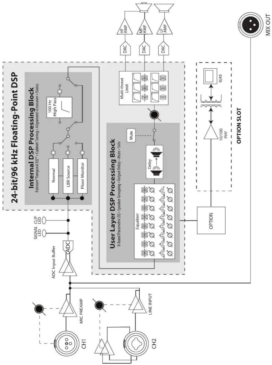
5.2 System Block Diagrams
5.2.1 Full-range Models
328AI
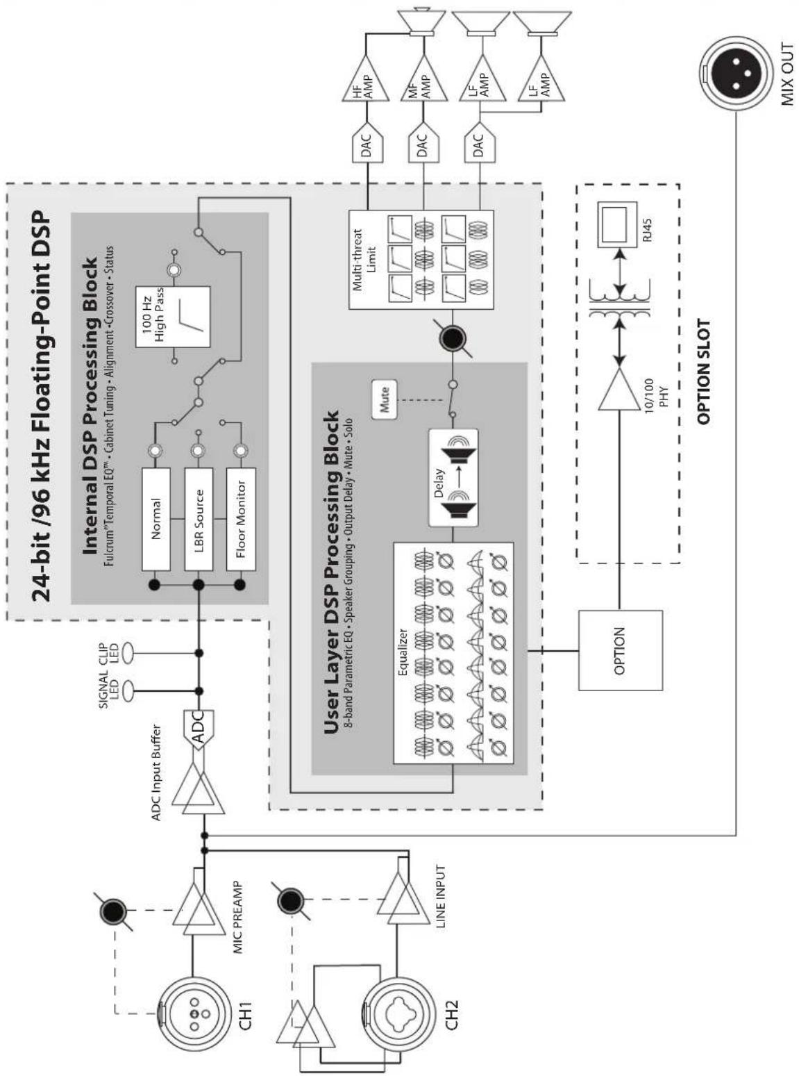
flowchart
graph TD
    A["24-bit /96 kHz Floating-Point DSP"] --> B["Internal DSP Processing Block"]
    B --> C["100 Hz High Pass"]
    C --> D["Normal"]
    C --> E["LBR Source"]
    C --> F["Floor Monitor"]
    D --> G["ADC Input Buffer"]
    E --> G
    F --> G
    G --> H["SIGNAL CLIP LED"]
    H --> I["ADC"]
    I --> J["MIC PREAMP"]
    J --> K["CH1"]
    J --> L["CH2"]
    K --> M["LINE INPUT"]
    L --> M
    M --> N["Line INPUT"]
    N --> O["CH1"]
    N --> P["CH2"]
    O --> Q["Mute"]
    P --> Q
    Q --> R["User Layer DSP Processing Block"]
    R --> S["8-band Parametric EQ • Speaker Grouping • Output Delay • Mute • Solo"]
    S --> T["Multi-threat Limit"]
    T --> U["DAC"]
    U --> V["HF AMP"]
    U --> W["MF AMP"]
    U --> X["LF AMP"]
    U --> Y["LF AMP"]
    T --> Z["Delay"]
    Z --> AA["Equalizer"]
    AA --> AB["RJ45"]
    AA --> AC["10/100 PHY"]
    AC --> AD["OPTION"]
    AD --> AE["MIX OUT"]
    AE --> AF["OPTION SLOT"]
312-315AI
flowchart
graph TD
    subgraph_DSP_Spass["24-bit/96 kHz Floating-Point DSP"]
        direction TB
        CH1["CH1"] --> MIC_PREAMP["MIC PREAMP"]
        MIC_PREAMP --> ADC["ADC Input Buffer"]
        ADC --> ADC1["ADC"]
        ADC1 --> SignalLED["SIGNAL LED"]
        ADC1 --> CLIPLED["CLIP LED"]
        CH2["CH2"] --> LINE_INPUT["LINE INPUT"]
        CH2 --> ChannelInput["Channel Input"]
    end

    subgraph_Internal_DSP_Processing["Internal DSP Processing Block"]
        direction TB
        Normal["Normal"] --> LBR_Source["LBR Source"]
        LBR Source --> FloorMonitor["Floor Monitor"]
        FloorMonitor --> HighPass["100 Hz High Pass"]
    end

    subgraph_User_Layer_DSP["User Layer DSP Processing Block"]
        direction TB
        Equalizer["Equalizer"] --> Delay["Delay"]
        Delay --> Mute["Mute"]
        Mute --> MultiThreatLimit["Multi-threat Limit"]
        MultiThreatLimit --> DAC1["DAC"] --> HFAMP["HF AMP"]
        MultiThreatLimit --> DAC2["DAC"] --> MFAMP["MF AMP"]
        MultiThreatLimit --> DAC3["DAC"] --> LFAMP["LF AMP"]
        ChannelInput --> OPTION["OPTION"]
        LineInput --> ChannelInput
        ChannelInput --> OptionSLOT["10/100 PHY"] --> RJ45["RJ45"]
    end

    subgraph_Options_Slot["Option Slot"]
        direction TB
        OPT1["OPTION"] --> Opt1["10/100 PHY"] --> RJ45
    end

    style DSP_Spass fill:#f9f,stroke:#333
    style User_Layer_DSP fill:#ccf,stroke:#333
5.2.2 18sAl Subwoofer
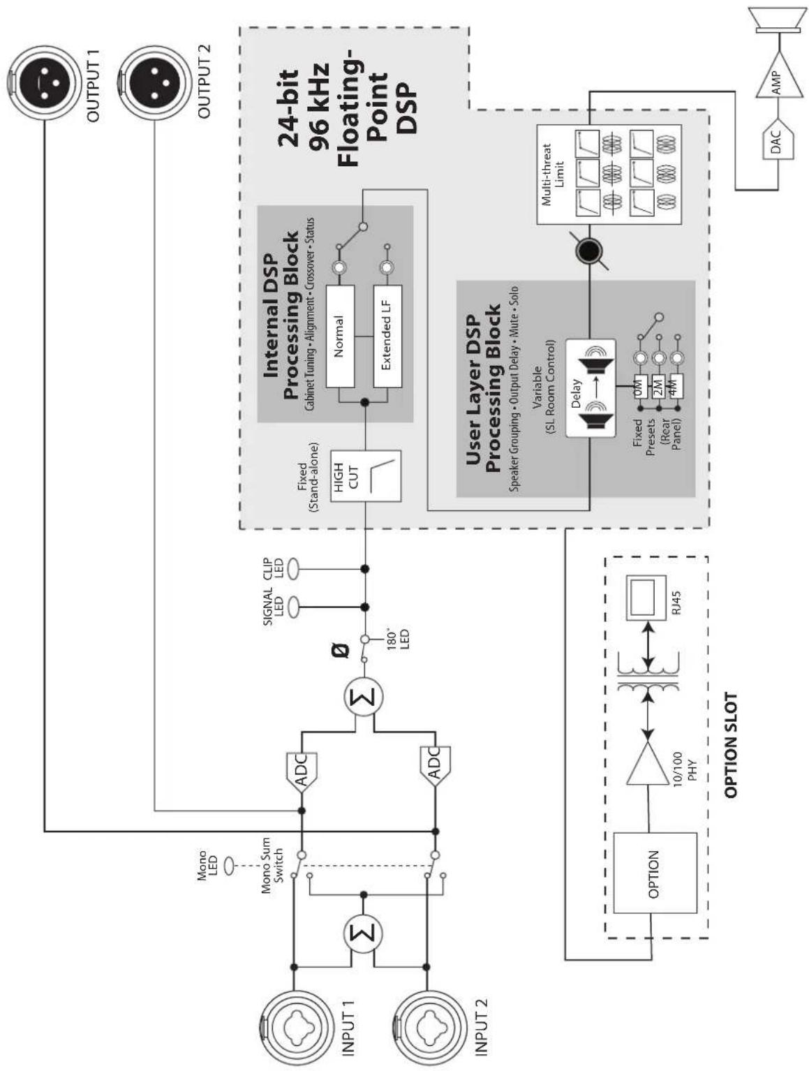
flowchart
graph TD
    subgraph_INPUT1["INPUT 1"]
        A["Input"] --> B["Σ"]
        C["Input"] --> D["ADC"]
        E["Input"] --> F["ADC"]
        G["Input"] --> H["Mono Sum Switch"]
        I["Input"] --> J["Mono LED"]
    end

    subgraph_INPUT2["INPUT 2"]
        K["Input"] --> L["Σ"]
        M["Input"] --> N["ADC"]
        O["Input"] --> P["ADC"]
        Q["Input"] --> R["Σ"]
        S["Input"] --> T["Signal LED"]
        U["Input"] --> V["CLIP LED"]
    end

    B --> W["180° LED"]
    D --> W
    F --> W
    R --> W
    T --> W
    U --> W
    V --> W
    W --> X["Fixed (Stand-alone)"]
    X --> Y["HIGH CUT"]
    Y --> Z["Internal DSP Processing Block"]
    Z --> AA["Cabinet Tuning • Alignment • Crossover • Status"]
    AA --> AB["Normal"]
    AA --> AC["Extended LF"]
    AB --> AD["User Layer DSP Processing Block"]
    AC --> AD
    AD --> AE["Speaker Grouping • Output Delay • Mute • Solo"]
    AE --> AF["Variable (SL Room Control)"]
    AF --> AG["Delay"]
    AG --> AH["Multi-threat Limit"]
    AH --> AI["DAC"]
    AI --> AJ["AMP"]
    AJ --> AK["DAC"]
    style INPUT1 fill:#f9f,stroke:#333
    style INPUT2 fill:#f9f,stroke:#333
    style INPUT1 fill:#ccf,stroke:#333
    style INPUT2 fill:#ccf,stroke:#333
5.3 Mechanical Drawings
5.3.1 StudioLive 312AI
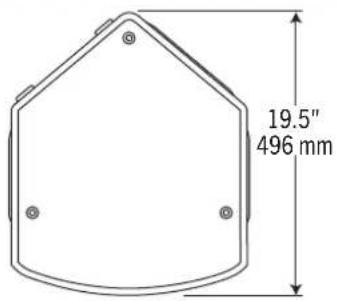
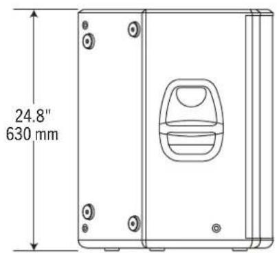
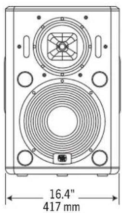
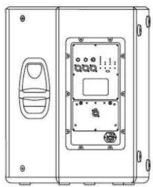
natural_image
Technical line drawing of a device rear panel with internal components and mounting holes (no text or symbols)5.3.2 StudioLive 315AI
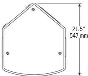
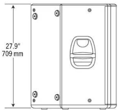
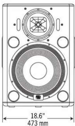
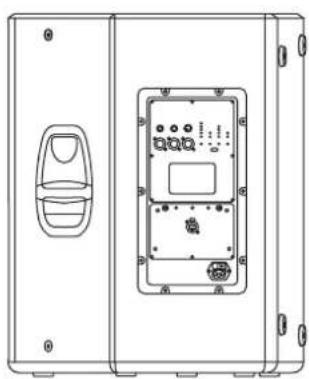
natural_image
Technical line drawing of a device casing with internal components and mounting holes (no text or symbols)5.3.3 StudioLive 328AI
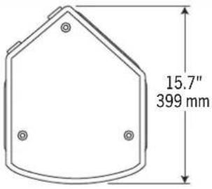
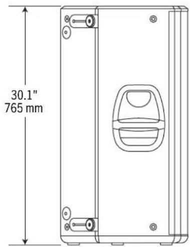
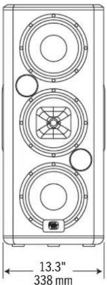
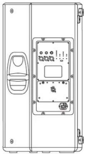
natural_image
Technical line drawing of a device enclosure with internal components and mounting holes (no text or symbols)5.3.4 StudioLive 18sAI
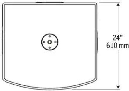
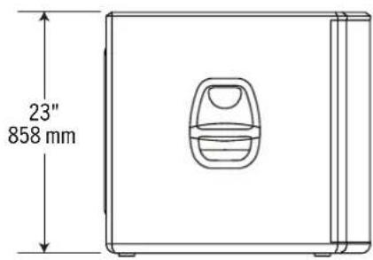
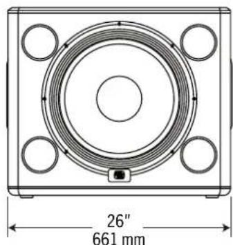
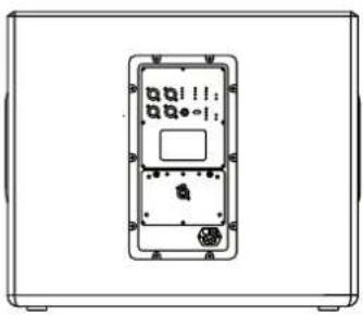
natural_image
Front view of a rectangular electronic device with internal components and indicator lights (no text or symbols visible)5.4 Optional Accessories
The following optional accessories are available through your PreSonus dealer.
Flying Kit (M10AI-KIT)
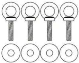
natural_image
Five identical mechanical components with circular and ring features, arranged in two rows (no text or symbols)The M10 Flying Kit is intended for use with all StudioLive AI-series full-range loudspeakers and includes four M10 eyebolts.
Custom Sub Pole (SP1BK)

Use the custom, threaded pole to mount a StudioLive AI-series full-range loudspeaker over an 18sAI subwoofer. Pole length has been measured and tested for system stability.
Platform Dolly for 18sAI (D18s)
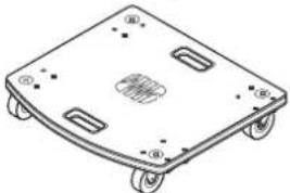
natural_image
Line drawing of a four-wheeled table with wheels and buttons (no text or symbols)This is a heavy-duty platform dolly that has been custom designed for stable, secure movement of the 18sAl subwoofer.
Protective Soft Covers
These protective soft covers are custom-fitted for each model. Tough, rip-resistant material protects loudspeaker cabinets during transportation. A cutout allows access to the handles. Order according to speaker model number.
6 Troubleshooting and Warranty
6.1 Support and Troubleshooting
Please check the PreSonus Web site (www.presonus.com) regularly for software information and updates, firmware updates, and support documentation, including frequently asked questions.
Online technical support is available at www.presonus.com/support/Contact-Technical-Support.
Technical support is available via email at techsupport@presonus.com.
PreSonus telephone technical support is available to customers in the USA on Monday through Friday from 9 a.m. to 5 p.m. Central Time by calling 1-225-216-7887. Customers outside of the USA should contact their national or regional distributor for telephone technical support. A list of international distributors is provided at www.presonus.com/buy/international_distributors.
Loudspeaker won't turn on.
If the loudspeaker is plugged in, and the switch is on, but no LEDs illuminate, check the following:
- Make sure the power cord is fully and securely inserted in the IEC receptacle and in the wall outlet.
- Confirm that the AC outlet is "live," using a tester or other device (such as a lamp) that is known to be working.
- If the loudspeaker still shows no power, it is possible that the internal fuse may have opened. This is not a user-serviceable part. Contact PreSonus technical support for more information.
Loudspeaker is on but there's no sound.
Check to make sure the signal is "live" from an external source. Check that output faders are up on the mixing console and check the output level using headphones.
If another speaker in a stereo configuration is working, swap input cables. If the problem moves, replace the faulty cable.
If the loudspeaker has been producing sound at high levels and then stops, it may have gone into thermal muting. Allow the unit to cool, and make sure the heat sink has sufficient ventilation.
Sound breaks up intermittently.
Check the input sources, using headphones, if possible, to determine if the problem is with the source.
Check console outputs and all input and loop-thru connectors to make sure they are securely plugged in. If the problem persists, try replacing cables with spares.
Distorted sound.
Check the input sources, using headphones, if possible, to make sure the signal is not already distorted.
Check the clip indicator on the rear panel or in SL Room Control monitoring. If the LED is lit all or most of the time, reduce the input levels.
Loudspeaker has hum or buzz.
Nearly all hum and buzz problems are related to cable grounding. With the loudspeaker at low volume, remove input and output cables, one at a time, until the noise disappears. Try replacing the suspect cable.
If you are using two-conductor cables with unbalanced 14 " connectors, try replacing with balanced cables using TRS or XLR connectors.
Try plugging loudspeakers and the external mixer into outlets that share a common ground. If necessary, use an extension cord to plug the external mixer into the same outlet as the loudspeaker—but do not run the AC cord bundled with signal cables.
6.2 Warranty
PreSonus's warranty obligations for this hardware product are limited to the terms set forth below:
How Consumer Law Relates To This Warranty:
THIS WARRANTY GIVES YOU SPECIFIC LEGAL RIGHTS, AND YOU MAY HAVE OTHER RIGHTS THAT VARY FROM STATE TO STATE (OR BY COUNTRY OR PROVINCE). OTHER THAN AS PERMITTED BY LAW, PRESONUS DOES NOT EXCLUDE, LIMIT OR SUSPEND OTHER RIGHTS YOU MAY HAVE, INCLUDING THOSE THAT MAY ARISE FROM THE NONCONFORMITY OF A SALES CONTRACT. FOR A FULL UNDERSTANDING OF YOUR RIGHTS YOU SHOULD CONSULT THE LAWS OF YOUR COUNTRY PROVINCE OR STATE.
PreSonus Products And EU Statutory Warranty:
When you purchase PreSonus products, European Union consumer law provides statutory warranty rights in addition to the coverage you receive from the PreSonus limited warranty. A summary of the EU Statutory Warranty and the PreSonus Limited Warranty is below:
| EU Consumer Law PreSonus Limited Warranty | ||
| Repair or Replacement Coverage For | Defects present when customer takes delivery | Defects arising after customer takes delivery |
| Warranty Period | 2 years (minimum) from original date of purchase (unless superseded by PreSonus) | 1 year from original date of purchase (unless superseded by PreSonus) |
| Cost of Coverage Provided at no additional cost Included at no additional cost | ||
| Who to contact to make a claim | The seller PreSonus technical support for your region | |
What This Warranty Covers:
PreSonus Audio Electronics, Inc., ("PreSonus") warrants defects in material and workmanship in PreSonus-branded products under normal use. This Limited Warranty applies only to hardware products manufactured by or for PreSonus that can be identified by the PreSonus trademark, trade name, or logo affixed to them.
Exclusions and Limitations:
This warranty does not cover the following:
- Damage caused by accident, abuse, improper installation, failure to follow instructions in the applicable owner's manual or improper operation, rental, product modification, alteration, or neglect.
- Damage from improper grounding, faulty wiring (AC and signal), faulty equipment, or connection to a voltage range outside published specifications (see applicable owner's manual).
- Damage to drivers or diaphragm assemblies found to have burnt voice coils from over/under driving or signal surge from another device.
-
Damage occurring during shipment or improper handling.
-
Damage caused by repair or service performed by persons not authorized by PreSonus.
- Products on which the serial number has been altered, defaced, or removed.
- Products purchased from an un-authorized PreSonus dealer (products that have transferable warranties are excluded from this provision provided the customer and the product are registered with PreSonus).
Who This Warranty Protects:
This Warranty protects only the original retail purchaser of the product (products that have transferable warranties are excluded from this provision provided the customer and the product are registered with PreSonus)
How Long This Warranty Lasts:
The Warranty begins on the original date of purchase from the retail purchaser and the duration is as follows:
| 1-Year Limited Warranty | ||
| Product Category Model Transferable | ||
| Recording Interfaces | AudioBox iOne, AudioBox iTwo, AudioBox Stereo, AudioBox Studio, AudioBox USB, AudioBox VSL (1818, 44, 22), FireStudio Project, FireStudio Mobile, FireStudio Mobile Studio, Music Creation Suite | No |
| Pre-amplifiers | ADL600, ADL700, BlueTube DP V2, DigiMax D8, Eureka, RC500, StudioChannel, TubePre V2 | No |
| StudioLive Mixers SL-1642, | SL-2442, SL-1602, SLM16.4.2 AI, SLM24.4.2 AI, SLM32.4.2AI No | |
| Monitoring & Controlling | Eris, Central Station Plus, FaderPort, HP4, HP60, Monitor Station, Monitor Station V2, Sceptre, Temblor | No |
| Signal Processing ACP88 No | ||
| Accessories | Covers, Dolly, PRM1 mic, Sub Pole, Breakout Cables, Power Supplies, M10 Kit | No |
| 3-Years Limited Warranty | ||
| Product Category Model Transferable | ||
| Live Sound StudioLive AI 328, 312, 315, S18 Yes | ||
What PreSonus Will Do:
PreSonus will repair or replace, at our sole and absolute option, products covered by this warranty at no charge for labor or materials. If the product must be shipped to PreSonus for warranty service, the customer must pay the initial shipping charges. PreSonus will pay the return shipping charges.
How to Get Warranty Service (USA):
- You must have an active user account with PreSonus and your hardware must be on file with your account. If you do not have an account, please go to: http://www.presonus.com/registration and complete the registration process.
- Contact our Technical Support Department at (225) 216-7887 or log a support ticket at: http://support.presonus.com. TO AVOID THE POSSIBILITY OF SENDING IN A PRODUCT THAT DOES NOT HAVE A PROBLEM, ALL SERVICE REQUESTS SHALL BE CONFIRMED BY OUR TECH SUPPORT DEPARTMENT.
- The return authorization number as well as shipping instructions shall be provided after your service request is reviewed and confirmed.
- The product should be returned for service in the original product packaging. Products may be shipped in a manufactured "flight" or "road" style cases but PreSonus will NOT cover any shipping damage to these cases. Products that are not shipped in the original product package or a manufactured case may not receive a warranty repair, at PreSonus's sole discretion. Depending on the product model and the condition of your original packaging, your product may not be returned to you in the original
packaging. The return shipping box may be a generic box that has been fitted for that model tested if the original gift box is not available.
How to Get Warranty Service (outside of USA):
- You must have an active user account with PreSonus and your hardware must be on file with your account. If you do not have an account, please go to: http://www.presonus.com/registration and complete the registration process.
- Contact the Technical Support/Service Department for your region at http://www.presonus.com/buy/international_distributors and follow procedures provided by your PreSonus contact.
Limitation of Implied Warranties:
ANY IMPLIED WARRANTIES, INCLUDING WARRANTIES OF MERCHANTABILITY AND FITNESS FOR A PARTICULAR PURPOSE, ARE LIMITED IN DURATION TO THE LENGTH OF THIS WARRANTY.
Some states, countries, or provinces do not allow limitations on how long an implied warranty lasts, so the above limitation may not apply to you.
Exclusion of Damages:
PRESONUS'S LIABILITY FOR ANY DEFECTIVE PRODUCT IS LIMITED TO THE REPAIR OR REPLACEMENT OF THE PRODUCT, AT PRESONUS'S SOLE OPTION. IF PRESONUS ELECTS TO REPLACE THE PRODUCT, THE REPLACEMENT MAY BE A RECONDITIONED UNIT. IN NO EVENT WILL PRESONUS BE LIABLE FOR DAMAGES BASED ON INCONVENIENCE, LOSS OF USE, LOST PROFITS, LOST SAVINGS, DAMAGE TO ANY OTHER EQUIPMENT OR OTHER ITEMS AT THE SITE OF USE, AND, TO THE EXTENT PERMITTED BY LAW, DAMAGES FOR PERSONAL INJURY, OR ANY OTHER DAMAGES WHETHER INCIDENTAL, CONSEQUENTIAL OR OTHERWISE, EVEN IF PRESONUS HAS BEEN ADVISED OF THE POSSIBILITY OF SUCH DAMAGES.
Some states, countries, or provinces do not allow limitations on how long an implied warranty lasts, so the above limitation may not apply to you.
If you have any questions about this warranty or service received, please contact PreSonus (USA) at (225) 216-7887 or one of our authorized international distributors at: http://www.presonus.com/buy/international_distributors.
Product features, design, and specifications are subject to change without notice.
Added bonus: PreSonus' previously Top Secret recipe for...
Jambalaya
Ingredients:
- 5 lbs link andouille sausage
- 3 lbs boneless chicken
- 2 lbs ground beef
•3 lbs onions (yellow or purple) - 2 stalks of celery
•1 lb bell peppers (green or red)
- 1 batch green onions
- 3 lbs rice
•Tony Chachere's Cajun Seasoning
- 1 bottle chicken stock concentrate (or 3 cubes chicken bullion)
- 1 can Rotel tomatoes with chilies, diced (regular hot)
- Tabasco sauce
Cooking Instructions:
- In a 16 qt. pot or larger, slice link sausage and pan-fry until brown.
- Add ground beef and brown.
- Do not remove from pot Add diced onions, celery, and bell peppers, 1 can Rotel Original diced tomatoes with chilies, 3 oz concentrate chicken stock, 12 teaspoon of Cajun seasoning, 1 teaspoon of Tabasco hot sauce (or more...maybe lots more).
- Cook until onions are translucent.
- Add chicken and cook until it turns white.
- Add diced green onions, 1 tsp. salt, 12 gallon water and bring to a boil.
- Add rice and bring to a boil. Cook on high for 8 minutes, covered, stirring every 2 minutes
- Cook covered on low for 10 minutes, stirring only once.
- Turn off and let sit for 30 minutes.
- Serve and enjoy!
Serves 20
StudioLive AI-Series Active Integration PA Speakers
Digital PA System with Active Integration
Owner's Manual