Touchlock SS K38 - Système de contrôle d'accès sécurisé Paxton - Free user manual and instructions
Find the device manual for free Touchlock SS K38 Paxton in PDF.

| Product Type | Standalone Secure Access Control System |
| Brand | Paxton |
| Model | Touchlock SS K38 |
| Dimensions (approx) | 120 mm x 60 mm x 30 mm |
| Weight (approx) | 0.45 kg |
| Power Supply | 4 x AA batteries (recommended) or 12V DC external |
| Battery Life | Up to 1 year under normal use |
| User Capacity | Up to 100 user codes and/or RFID tokens |
| Operating Modes | PIN code, RFID card, or combination |
| Lock Type | Electromagnetic or motorized deadbolt (internal) |
| Weather Resistance | IP54 rated (suitable for outdoor use under cover) |
| Operating Temperature | -10°C to 50°C |
| Key Override | Yes, mechanical key included |
| Audible/Visual Indicators | Buzzer and multi-color LED |
| Tamper Alarm | Built-in tamper switch triggers alarm if cover removed |
| Mounting | Surface mount on door or wall, template included |
| Maintenance | Wipe with a damp cloth, do not use solvents |
| Spare Parts Available | Batteries, screws, RFID tokens, external power supply |
| Repairability | Modular design; firmware updates via micro-USB |
| Warranty | 2 years (manufacturer warranty) |
| Compliance | CE, FCC, RoHS |
Frequently Asked Questions - Touchlock SS K38 Paxton
User questions about Touchlock SS K38 Paxton
0 question about this device. Answer the ones you know or ask your own.
Ask a new question about this device
Download the instructions for your Système de contrôle d'accès sécurisé in PDF format for free! Find your manual Touchlock SS K38 - Paxton and take your electronic device back in hand. On this page are published all the documents necessary for the use of your device. Touchlock SS K38 by Paxton.
USER MANUAL Touchlock SS K38 Paxton
Technical help is available: Monday - Friday from 07:00 - 19:00 (GMT)
Saturday from 09:00 - 13:00 (GMT)
Documentation on all Paxton products can be found on our website - http://www.paxton.co.uk/
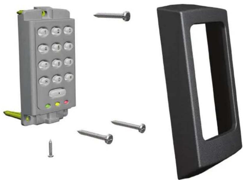
Fitting
natural_image
3D renderings of a gray industrial control panel with yellow and red buttons, surrounded by screws and a black plastic door (no text or symbols)K75 Screw connector option
The unit should be mounted in conjunction with an electrical backbox to achieve the required clearance for the connector.
If an adaptor plate (310-750) is fitted, the mountings on the backbox can also be used.
Indoor use only
natural_image
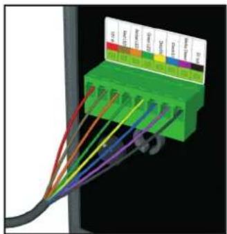
3D diagram of a green connector with multiple colored wires connected to a black cable (no text or symbols visible)Cable extensions
Readers can be extended using Belden CR9540 10-core overall screened cable to a maximum of 100 metres.
Illustrations in this instruction show the standard keypad.
The Stainless Steel version installs and operates in exactly the same manner.
Wiring
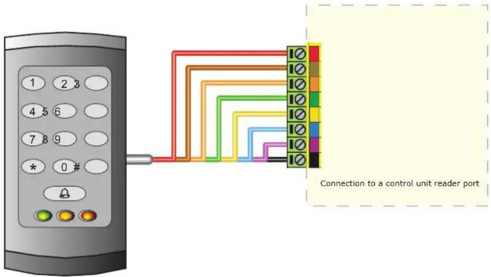
When using this keypad style with Net2, the software version used must be v3.21 or later.
WHITE labelled Net2 control units provide 5V at the Red terminal. The Red power wire for the reader should therefore be directly connected to the 12V ACU terminal.
Switch2 controllers with WHITE labels are incompatible with these products. The keypads in the K and KP series, can only be used with Switch2 controllers fitted with YELLOW wiring labels.
Connection modules

Reader junction box (325-020)
This module can be used to provide a connection point for the reader RJ45 plug. The terminals on the module are then wired colour for colour to the controller.
Alternatively, the reader can be wired directly into the screw terminals of the control unit by first cutting off the RJ45 plug and stripping back the wires in the cable.
Reader port module (325-030)
This module may be purchased separately to speed up the installation and replacement of readers.
The reader port module is designed to convert the standard reader ports on Switch2 and Net2 controllers to accept one or two RJ45 connections. Pull off the screw terminal block from the reader port and simply replace it with this module.
Technical Help
Here is the list of topics about this product that receive the most technical support enquiries.
We list them here to help you speed up the installation and trouble shooting process.
1 - Net2 - Bell function.
Pressing the bell button on the keypad will result in Relay 2 being energised for 1 second. A bell sounder can be controlled by wiring one of the bell feeds across COM / NO on the relay.
2 - Readers/keypads not working.
- Software settings - Confirm that the settings of the reader or keypad are correct.
- Connections - Check the wiring of the connectors. Where possible, test this reader on the other port.
- Extended Cable - Belden 9540 should be used. (100 m maximum) Twisted pair alarm cable should not be used. To confirm that an extended cable is not at fault, wire the reader direct into the reader port.
- Supply voltage - Confirm that the voltage is within specification. (see table)
- User token - Confirm that the user token used for testing is OK by presenting it to a known working reader.
- Interference - Confirm whether the reader works when tested 'in hand' and not mounted on the wall. Ensure that readers are not mounted back to back or there is no interference from other local RF devices.
3 - Readers/keypads - Extending cable.
Only Belden CR9538 / 9540 can be used for cable extensions. CR9538 8 core up to 25 m, CR9540 10 core for 25-100 m (maximum extension). With CR9540, the two additional cores should be used to double up for power.
4 - Switch2 - Initialising with 2 keypads.
Either Keypad can be used to initialise the controller. Connect all wires in parallel, colour for colour.
5 - Switch2 (White label) & Touchlock Switch Control (922-177).
This keypad style does NOT work with these control units.
6 - Duress Codes.
Net2 - Duress codes cannot be programmed into Net2.
Switch2 - These systems can accept Duress codes.
7 - Net2 - Replacing an old style keypad. (ACU Keypad port).
When using this keypad with Net2, the software version used must be V3.21 or later and the keypad must be wired into the reader port.
8 - Net2 - Keypad hacker event.
The event 'Keypad hacker' is produced when 20 incorrect digits are entered into a keypad.
9 - Switch2 - Touchlock Membrane keypad replacement.
The K and KP series range, can only be used with Switch2 control units fitted with yellow wiring labels.
Earlier versions of the Switch2 are incompatible with these products.
10 - Net2 - Using KP readers.
KP readers can be used with any version of Net2 since v3.21.
Settings should be: Reader type: Paxton reader / Keypad type: Paxton keypad.
Suitability
Security-sensitive doors
Wet environments


Mounted on metal surface
Readers mounted together
K


KP

300mm
between readers
Keypad bezels
Additional bezels are available in black, white, grey, blue and silver. Registered installers can order these free of charge by logging onto the secure installer extranet: http://paxton.info/1035 or if you are not a registered installer please call us on: 01273 811011 for more information.
natural_image
Close-up of a gray electronic device's control panel with buttons and a red indicator light (no readable text or symbols)
natural_image
Close-up of a black remote control device with buttons and a green indicator light (no readable text or symbols)
natural_image
Close-up of a black electronic device's control panel with buttons and a red indicator light (no readable text or symbols)
natural_image
Close-up of a white remote control device with buttons and a green-lit button (no readable text or symbols)
natural_image
Close-up of a white electronic device with green and yellow buttons, no visible text or symbolsSpecifications
| Environment | Min | Max | |
| Operating temperatures - all items | - 35 °C | + 66 °C | |
| Waterproof - Fixed cable | IPX7 | Outdoor use | |
| Waterproof - K75 - Screw connection | Indoor use | ||
| Cable length | 5 metres | ||
| Vandal resistance - Stainless steel keypad | Medium | ||
| Vandal resistance - Standard keypad | Low | ||
| Electrical | |||
| Voltage | 10V DC 14V DC | ||
| Current | 120 mA | ||
| Clock and data bit period | 600 μs | ||
| Backlight | Not with Stainless Steel keypad | ||
| Dimensions | Width | Height | Depth |
| K38 38 mm 78 mm | 13 mm | ||
| K50 50 mm 100 mm | 15 mm | ||
| K75 75 mm 143 mm | 16 mm | ||
KP Specific
| Electrical | Min | Max | |
| Voltage | 10V DC | 14V DC | |
| Current | 180 mA | ||
| Clock and data bit period | 600 μs | ||
| Carrier frequency | 125 KHz | ||
| Dimensions | Width | Height | Depth |
| KP50 50 mm 100 mm | 15 mm | ||
| KP75 75 mm 143 mm | 16 mm | ||
| Read Range | Token | Keyfob Hands Free Token | |
| KP50 80 mm 50 mm | 1100 mm | ||
| KP75 100 mm 60 mm | 1500 mm | ||
This product is not suitable for retail sale. All warranties are invalid if this product is not installed by a competent person.