
NH-L12 - PC Fan Noctua - Free user manual and instructions
Find the device manual for free NH-L12 Noctua in PDF.


| Product Type | CPU Cooler (Top-Flow Design) |
| Brand | Noctua |
| Model | NH-L12 |
| Socket Compatibility | Intel LGA2011, LGA1366, LGA115x, LGA775; AMD (with stock backplate) |
| Dimensions (with both fans) | Approx. 93 x 128 x 93 mm (with NF-F12 and NF-B9) |
| Height (with only NF-B9 fan) | 66 mm |
| Weight | Approx. 530 g (with both fans and mounting) |
| Fans Included | 1x NF-B9 (92mm) and 1x NF-F12 (120mm) PWM |
| Fan Speed (max.) | NF-B9: 1600 RPM; NF-F12: 1500 RPM |
| Noise Level (max.) | NF-B9: 17.6 dB(A); NF-F12: 22.4 dB(A) |
| Airflow (max.) | NF-B9: 40.8 CFM; NF-F12: 55 CFM |
| Mounting System | SecuFirm2™ with backplate (Intel) or stock backplate (AMD) |
| Thermal Paste Included | NT-H1 (high-grade hybrid) |
| Low-Noise Adapters Included | NA-RC6 (for NF-F12) and NA-RC7 (for NF-B9) |
| Y-Split Cable Included | NA-YC1 for dual fan connection |
| Vibration Compensators Included | Silicone anti-vibration pads for fan mounting |
| Warranty | 6 years (manufacturer defect) |
| Recommended Application | HTPC, Small Form Factor (SFF), quiet PC builds |
| Certifications | RoHS, WEEE |
| Package Contents | Heatsink, NF-F12 fan, NF-B9 fan, SecuFirm2 mounting kit, NT-H1 paste, L.N.A. adapters, y-cable, screws, manual |
Frequently Asked Questions - NH-L12 Noctua
User questions about NH-L12 Noctua
0 question about this device. Answer the ones you know or ask your own.
Ask a new question about this device
Download the instructions for your PC Fan in PDF format for free! Find your manual NH-L12 - Noctua and take your electronic device back in hand. On this page are published all the documents necessary for the use of your device. NH-L12 by Noctua.
USER MANUAL NH-L12 Noctua
Congratulations on choosing the Noctua NH-L12. This smaller size cooler packs all essential technologies of our award-winning high-end models into a highly compact package in order to give you the best possible quiet cooling experience for HTPCs and small form factor builds. I'm confident that you will be able to sense some of the research, attention and care we've put into making this product. Enjoy your NH-L12!
Yours sincerely,
This manual will guide you through the installation process of the SecuFirm2™ mounting system step by step. Prior to installing the cooler, please consult the compatibility list on our website (www.noctua.at/compatibility) and verify that the cooler is fully compatible with your motherboard. Should you encounter any difficulties, please check the FAQs on our website (www.noctua.at/faqs) and don't hesitate to contact our support team at support@noctua.at. Noctua cannot be held responsible for any damage or losses caused by compatibility issues.
Multilingual versions of this manual are available on our website: www.noctva.at/manuals
Required mounting parts:
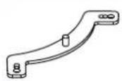
2x NM-IMB2
Mounting-Bars
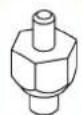
4x NM-IBT2
Bolts
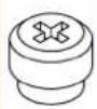
4x NM-ITS1
Thumbscrews
Step 1
Installing the mounting-bars
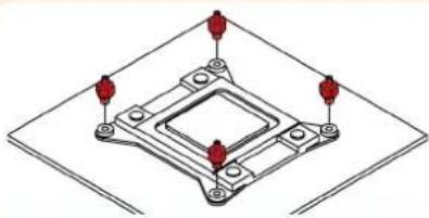
First screw the NM-IBT2 bolts into the screw threads of the LGA2011 socket frame.
natural_image
Isometric diagram of a mechanical component with four red pins and mounting holes (no text or symbols)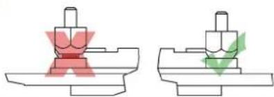
natural_image
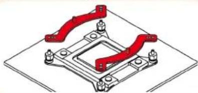
Two mechanical component diagrams showing a red cross-shaped component and a green checkmark on a base (no text or symbols)Then put the NM-IMB2 mounting-bars onto the bolts.
natural_image
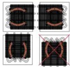
Isometric diagram of a mechanical assembly with red brackets and mounting holes (no text or symbols)Caution: Choose the alignment of the mounting bars according to the desired final orientation of the cooler:
Caution: In tower style cases, please avoid installing the NH-L12 with the bends of the heatpipes pointing upwards as this may result in reduced cooling performance.
natural_image
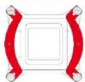
Four-panel diagram showing a grid structure with curved and intersecting lines, no text or symbols present.Caution: Make sure that the curved sides of the mounting bars are pointing outwards.
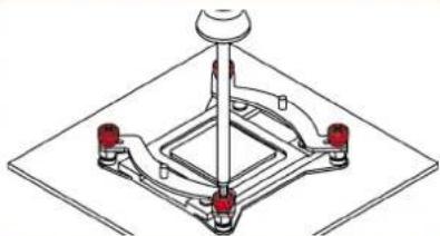
Fix the mounting bars using the NM-ITS1 thumbscrews.
natural_image
Technical line drawing of a mechanical assembly with red components and a central hub (no text or symbols)Caution: Gently tighten the screws until they stop, but don't use excessive force.
Step 2
Applying thermal paste
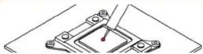
If there are residual traces of thermal paste or thermal pads on your CPU, please clean them off first. Then press a small drop (4-5mm diameter) of NT-H1 onto the centre of the heatspreader.
natural_image
Technical line drawing of a mechanical clamp or bracket assembly (no text or symbols)Caution: Applying too much thermal paste will lower the heat conductivity and cooling performance!
Step 3
Fastening the heatsink to the CPU
Caution: Please first take off the protection cover at the bottom side of the heatsink and remove the rubber support bar between the bottom fan and the base of the heatsink!
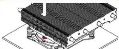
Take off the top fan. Then put the heatsink onto the CPU and screw it to the screw threads of the mounting bars. Note that you can reach through the blades of the lower fan using the supplied screw driver. There is thus no need to take off the lower fan for installation.
natural_image
Technical illustration of a heat exchanger or cooling unit with cooling fins and cooling elements (no text or symbols)Caution: Tighten the screws until they stop.
Step 4
Fan Setup
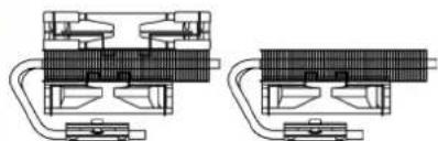
The NH-L12 can be used with both fans for maximum performance or with the NF-B9 fan only in order to reduce the total height to 66mm:
natural_image
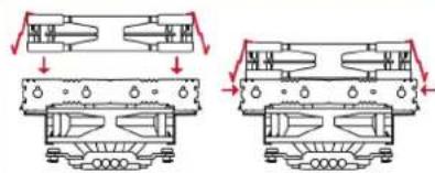
Technical line drawing of two mechanical components with no visible text or symbolsIf you want to use both fans, put the NF-F12 fan back on. If you don't run the NF-F12 on the CPU cooler, you can use the supplied fan screws or silicone Vibration-Compensators to install it inside your case.
natural_image
Technical line drawing of two mechanical components with downward force arrows indicating compression or assembly (no text or symbols)Step 1 Step 2
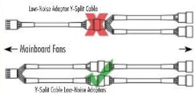
Connect the fan(s) to the mainboard. Use the supplied NA-YCI y-split cable to connect both fans to one fan header.
Depending on your CPU and the temperature inside the case, you may interconnect the supplied NA-RC6 and NA-RC7 Low-Noise Adapters (L.N.A.) in order to further reduce the fans operating noise. Use the NA-RC6 for the NF-F12 120mm fan and the NA-RC7 for the NF-B9 92mm fan.
Caution: Never use one adaptor for both fans by putting it before the y-split cable.
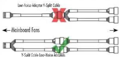
Caution: When using the L.N.A., check the temperature of your CPU using appropriate software (e.g. the respective applications of your mainboard manufacturer), in order to evade automatic throttling of the CPU due to the increased temperature. If the cooling performance is insufficient, please increase case ventilation or remove the L.N.A.
Warranty, Support and FAQs
Even with high-grade products and strict quality control, the possibility of defects cannot be eliminated entirely. Therefore, we aim at providing the highest possible level of reliability and convenience by offering a warranty period of 6 years and direct, fast and straightforward RMA service.
Should you encounter any problems with your NH-L12, please don't hesitate to contact our support team (support@noctua.at).
Please also consult the FAQ section on our website: www.noctua.at/faqs.
Dear customer,
Congratulations on choosing the Noctua NH-L12. This smaller size cooler packs all essential technologies of our award-winning high-end models into a highly compact package in order to give you the best possible quiet cooling experience for HTPCs and small form factor builds. I'm confident that you will be able to sense some of the research, attention and care we've put into making this product. Enjoy your NH-L12!
Yours sincerely,
Roland Massig, Noctua CEO
This manual will guide you through the installation process of the SecuFirm2™ mounting system step by step. Prior to installing the cooler, please consult the compatibility list on our website (www.noctua.at/compatibility) and verify that the cooler is fully compatible with your motherboard. Should you encounter any difficulties, please check the FAQs on our website (www.noctua.at/faqs) and don't hesitate to contact our support team at support@noctua.at. Noctua cannot be held responsible for any damage or losses caused by compatibility issues.
Multilingual versions of this manual are available on our website: www.noctua.at/manuals
Required mounting parts:
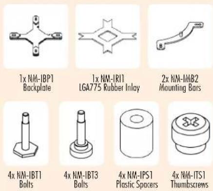
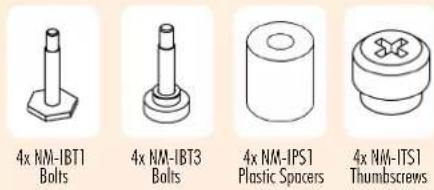
Step 1
Removing the mainboard
In case you want to use the cooler on an assembled system, you first have to remove the mainboard from the case in order to be able to install the supplied backplate.
Caution: On LGA1366 and LGA115x, the supplied backplate will install over the mainboard's stock backplate, so the mainboard's stock backplate must not be taken off.
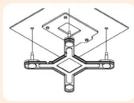
natural_image
Technical line drawing of a mechanical clamp or bracket assembly (no text or symbols)Caution: Some Mini-ITX mainboards have larger components (such as capacitors or I/O Chips) on the rear side that would make contact with the NM-IBP1 backplate. As there is a risk of damaging the mainboard when the backplate presses onto these components, please use the supplied NM-IBT3 bolts instead of the NM-IBP1 backplate and NM-IBT1 bolts when installing the NH-L12 on mainboards with larger components on the rear side. Proceed with Step 4 after inserting the NM-IBT3 bolts as shown below. If in doubt, please consult the compatibility list of www.noctua.at/compatibility or contact our support team!
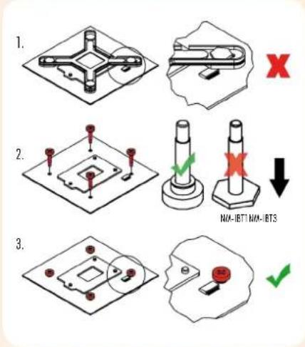
Step 2
Setting up the backplate
First put the four NM-IBT1 bolts into the holes appropriate for your main-board's CPU socket.
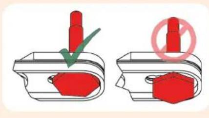
Caution: Make sure to use NM-IBT1 and not NM-IBT3!
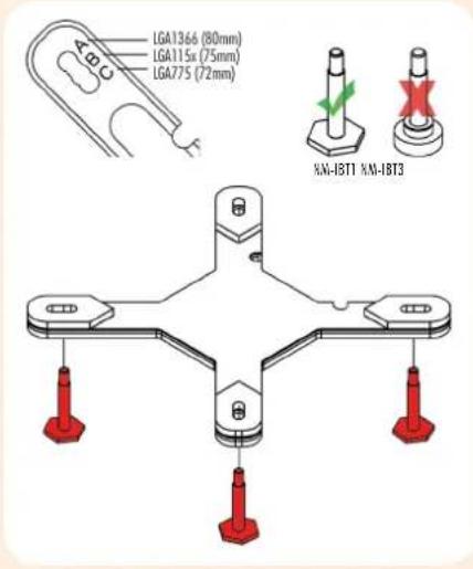
Caution: Please verify that all four NM-IBT1 bolts are put into the appropriate holes and fully pushed in.
For use on LGA1366 and LGA115x mainboards, please remove the rubber inlay. Make sure that the rubber inlay is in place for LGA775.
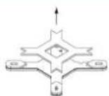
LGA1366 & LGA115x
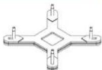
LGA775
Step 3
Attaching the backplate
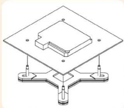
Place the backplate on the rear side of the mainboard so that the bolts stick through the mounting holes.
natural_image
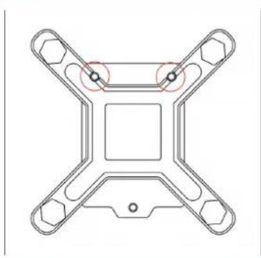
Technical line drawing of a mechanical assembly with mounting base and central component (no text or symbols)Caution: On LGA115x, please make sure that the two cuts in the supplied backplate align with the screws of the mainboard's stock backplate.
natural_image
Pure technical diagram of a mechanical component with four symmetrical arms and central square (no text or symbols)Step 4
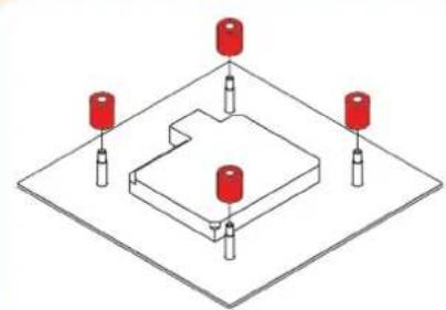
Installing the mounting bars
First put the plastic spacers onto the bolts, then add the mounting bars.
natural_image
Isometric diagram of a mechanical assembly with four red cylindrical components mounted on a base plate (no text or symbols)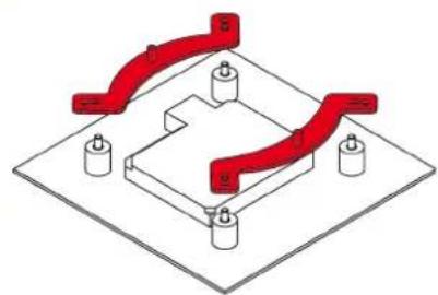
natural_image
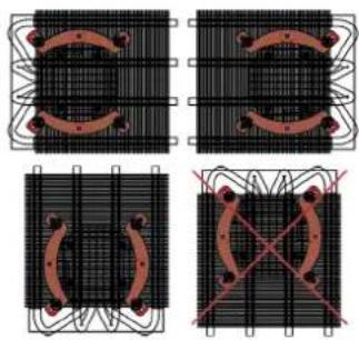
Pure mechanical assembly diagram showing red curved components mounted on a base plate (no text or symbols)Caution: Choose the alignment of the mounting bars according to the desired final orientation of the cooler:
natural_image
Four-panel diagram showing mechanical or electrical component layouts with no visible text, numbers, or symbols.Caution: In tower style cases, please avoid installing the NH-L12 with the bends of the heatpipes pointing upwards as this may result in reduced cooling performance.
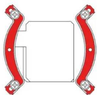
Caution: Make sure that the curved sides of the mounting bars are pointing outwards.
natural_image
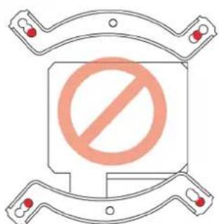
Pure mechanical component diagram with red brackets and mounting holes, no text or symbols presentCaution: Make sure to use the correct holes on the mounting bars.
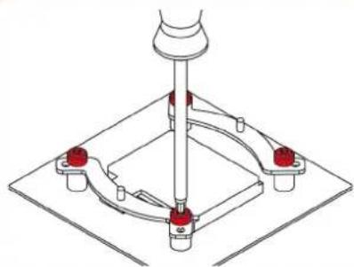
Fix the mounting bars using the 4 thumb screws.
natural_image
Technical line drawing of a mechanical assembly with red components and a central vertical rod (no text or symbols)Caution: Gently tighten the screws until they stop, but don't use excessive force.
Step 5
Applying thermal paste
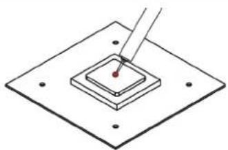
If there are residual traces of thermal paste or thermal pads on your CPU, please clean them off first. Then press a small drop (4-5mm diameter) of NT-H1 onto the centre of the heat-spreader.
natural_image
Diagram of a microfluidic device with a needle inserted into a square chamber (no text or symbols)Caution: Applying too much thermal paste will lower the heat conductivity and cooling performance!
Step 6
Fastening the heatsink to the CPU
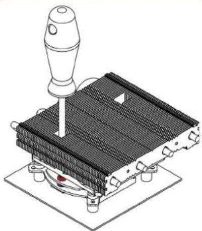
Caution: Please first take off the protection cover at the bottom side of the heatsink and remove the rubber support bar between the bottom fan and the base of the heatsink!
Take off the top fan. Then put the heatsink onto the CPU and screw it to the screw threads of the mounting bars. Note that you can reach through the blades of the lower fan using the supplied screw driver. There is thus no need to take off the lower fan for installation.
natural_image
Isometric illustration of a mechanical device with a lever and cooling fins (no text or symbols)Caution: Tighten the screws until they stop.
Step 7
Fan Setup
The NH-L12 can be used with both fans for maximum performance or with the NF-B9 fan only in order to reduce the total height to 66mm:
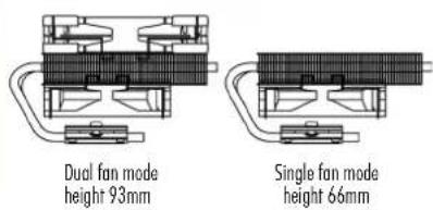
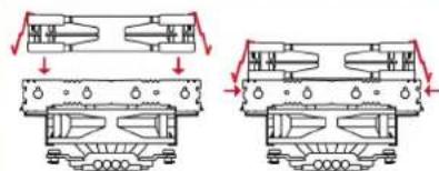
If you want to use both fans, put the NF-F12 fan back on. If you don't run the NF-F12 on the CPU cooler, you can use the supplied fan screws or silicone Vibration-Compensators to install it inside your case.
natural_image
Technical line drawing of two mechanical components with mounting holes and internal cavities (no text or symbols)Step 1 Step 2
Connect the fan(s) to the mainboard. Use the supplied NA-YC1 y-split cable to connect both fans to one fan header.
Depending on your CPU and the temperature inside the case, you may interconnect the supplied NA-RC6 and NA-RC7 Low-Noise Adapters (L.N.A.) in order to further reduce the fans operating noise. Use the NA-RC6 for the NF-F12 120mm fan and the NA-RC7 for the NF-B9 92mm fan.
Caution: Never use one adaptor for both fans by putting it before the y-split cable.
Caution: When using the L.N.A., check the temperature of your CPU using appropriate software (e.g. the respective applications of your mainboard manufacturer), in order to evade automatic throttling of the CPU due to the increased temperature. If the cooling performance is insufficient, please increase case ventilation or remove the L.N.A.
Warranty, Support and FAQs
Even with high-grade products and strict quality control, the possibility of defects cannot be eliminated entirely. Therefore, we aim at providing the highest possible level of reliability and convenience by offering a warranty period of 6 years and direct, fast and straightforward RMA service.
Should you encounter any problems with your NH-L12, please don't hesitate to contact our support team (support@noctua.at).
Please also consult the FAQ section on our website: www.noctua.at/faqs.
Dear customer,
Congratulations on choosing the Noctua NH-L12. This smaller size cooler packs all essential technologies of our award-winning high-end models into a highly compact package in order to give you the best possible quiet cooling experience for HTPCs and small form factor builds. I'm confident that you will be able to sense some of the research, attention and care we've put into making this product. Enjoy your NH-L12!
Yours sincerely,
Roland Mossig, Noctua CEO
This manual will guide you through the installation process of the SecuFirm2™ mounting system step by step. Prior to installing the cooler, please consult the compatibility list on our website (www.noc-tua.at/compatibility) and verify that the cooler is fully compatible with your motherboard.
Should you encounter any difficulties, please check the FAQs on our website (www.noctua.at/faqs) and don't hesitate to contact our support team at support@noctua.at. Noctua cannot be held responsible for any damage or losses caused by compatibility issues.
Multilingual versions of this manual are available on our website: www.noctua.at/manuals
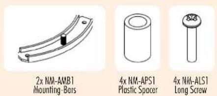
Required mounting parts:
Caution: The SecuFirm2™ mounting system requires a backplate, which is preinstalled on most AMD mainboards.
If your mainboard doesn't have a backplate, please contact our support team at support@noctva.at.
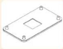
AMD stock backplate
Step 1 Removing the retention module
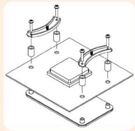
If your mainboard uses a retention module for CPU cooler installation, please remove it first. The SecuFirm2 ^™ mounting system will install directly to your mainboard's stock backplate on the rear side of the socket.
Step 2 Attaching the mounting bars
First put the plastic spacers onto the screw threads, then fix the mounting bars using the 4 long screws.
natural_image
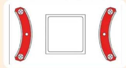
Technical line drawing of a mechanical assembly with mounting base and cylindrical components (no text or symbols)Caution: Make sure that the curved sides of the mounting bars are pointing inwards.
natural_image
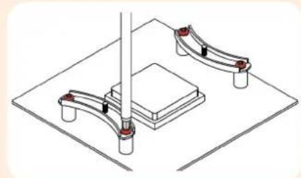
Two red curved mechanical components with mounting holes, one centered within a square frame (no text or symbols)Caution: Tighten the screws until they stop.
natural_image
Isometric diagram of a mechanical assembly with two curved components mounted on a base plate (no text or symbols)Step 3 Applying thermal paste
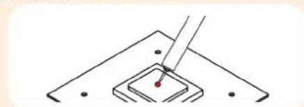
If there are residual traces of thermal paste or thermal pads on your CPU, please clean them off first. Then press a small drop (4-5mm diameter) of NT-H1 onto the centre of the heatspreader.
natural_image
Simple line drawing of a tool interacting with a square component (no text or symbols)Caution: Applying too much thermal paste will lower the heat conductivity and cooling performance!
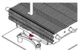
Step 4 Fastening the heatsink to the CPU
Caution: Please first take off the protection cover at the bottom side of the heatsink and remove the rubber support bar between the bottom fan and the base of the heatsink!
Put the heatsink onto the CPU and screw it to the screw threads of the mounting bars.
natural_image
Diagram of a heat exchanger or cooling unit with cooling fins and a red indicator light (no text or symbols)Caution: Tighten the screws until they stop.
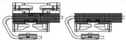
Step 5 Fan Setup
The NH-L12 can be used with both fans for maximum performance or with the NF-B9 fan only in order to reduce the total height to 66mm:
natural_image
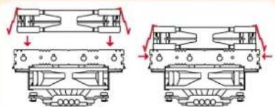
Technical line drawing of two mechanical components with no visible text or symbolsIf you want to use both fans, put the NF-F12 fan back on. If you don't run the NF-F12 on the CPU cooler, you can use the supplied fan screws or silicone Vibration-Compensators to install it inside your case.
natural_image
Technical diagram showing two mechanical assembly configurations with downward force arrows (no text or labels)step 1 step 2
Connect the fan(s) to the mainboard. Use the supplied NA-YC1 y-split cable to connect both fans to one fan header. Depending on your CPU and the temperature inside the case, you may interconnect the supplied NA-RC6 and NA-RC7 Low-Noise Adapters (L.N.A.) in order to further reduce the fans operating noise. Use the NA-RC6 for the NF-F12 120mm fan and the NA-RC7 for the NF-B9 92mm fan.
Caution: Never use one adaptor for both fans by putting it before the y-split cable.
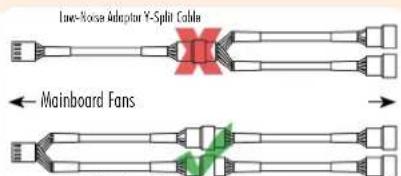
Y-Split Cable Low-Noise Adaptors
Caution: When using the L.N.A., check the temperature of your CPU using appropriate software (e.g. the respective applications of your mainboard manufacturer), in order to evade automatic throttling of the CPU due to the increased temperature. If the cooling performance is insufficient, please increase case ventilation or remove the L.N.A.
Warranty, Support and FAQs
Even with high-grade products and strict quality control, the possibility of defects cannot be eliminated entirely. Therefore, we aim at providing the highest possible level of reliability and convenience by offering a warranty period of 6 years and direct, fast and straightforward RMA service. Should you encounter any problems with your NH-L12, please don't hesitate to contact our support team (support@noctua.at). Please also consult the FAQ section on our website: www.noctua.at/faqs.
- Installing the mounting-bars
- Applying thermal paste
- Fastening the heatsink to the CPU
- Fan Setup
- Warranty, Support and FAQs
- Removing the mainboard
- Setting up the backplate
- Attaching the backplate
- Installing the mounting bars
- Step 5
- Step 6
- Step 7
- Step 1 Removing the retention module
- Step 2 Attaching the mounting bars
- Step 3 Applying thermal paste
- Step 4 Fastening the heatsink to the CPU
- Step 5 Fan Setup
Brand : Noctua
Model : NH-L12
Category : PC Fan