
Protect B 2300 PRO - Inverter AEG - Free user manual and instructions
Find the device manual for free Protect B 2300 PRO AEG in PDF.

| Product Type | Line-interactive UPS (Uninterruptible Power Supply) |
| Model | Protect B 2300 PRO |
| Power Rating | 2300 VA / 2300 W |
| Input Voltage | 220-240 V AC |
| Output Voltage | 220-240 V AC ± 10% |
| Waveform | Pure sine wave |
| Battery Type | Sealed lead-acid, maintenance-free |
| Battery Capacity | 12 V / 9 Ah (internal) |
| Dimensions (H x W x D) | 310 x 200 x 460 mm |
| Weight | Approx. 18 kg |
| Color | Black |
| Protections | Overload, short circuit, overvoltage, undervoltage, surge |
| Interfaces | USB, RS-232, audible alarm |
| Cooling | Variable speed fan |
| Operating Temperature | 0°C to 40°C |
| Humidity | 0-95% non-condensing |
| Noise Level | < 50 dBA at 1 meter |
| Battery Replacement | Hot-swappable, user-replaceable |
| Standard Outlets | 4 x IEC 320 C13 (or similar) |
| Certifications | CE, TUV, RoHS |
Frequently Asked Questions - Protect B 2300 PRO AEG
User questions about Protect B 2300 PRO AEG
0 question about this device. Answer the ones you know or ask your own.
Ask a new question about this device
Download the instructions for your Inverter in PDF format for free! Find your manual Protect B 2300 PRO - AEG and take your electronic device back in hand. On this page are published all the documents necessary for the use of your device. Protect B 2300 PRO by AEG.
USER MANUAL Protect B 2300 PRO AEG
natural_image
Two electronic devices: a tall digital display unit and a black-and-white rack device (no visible text or symbols)PROTECT B. 750 PRO
PROTECT B. 1000 PRO
PROTECT B. 1400 PRO
PROTECT B. 1800 (BP) PRO
PROTECT B. 2300 PRO
PROTECT B. 3000 PRO
Thank you for deciding to purchase the PROTECT B.PRO from AEG Power Solutions.
The following safety precautions are an important part of these operating instructions. They are designed to help you avoid problems caused by operating errors and to protect you against any possible hazards. Please make sure to read through these instructions carefully before using the product for the first time!
1 Notes on these Operating Instructions
Duty to provide information
These operating instructions are designed to help you properly and safely install and operate the following _Uinterruptible Power Supply (UPS) systems: the PROTECT B.750 PRO, the PROTECT B.1000 PRO, the PROTECT B.1400 PRO, the PROTECT B.1800 PRO, the PROTECT B.2300 PRO or the PROTECT B.3000 PRO as well as the corresponding external battery unit: the PROTECT B.1800 BP PRO, hereinafter referred to as the PROTECT B.PRO. These operating instructions contain important information on how to avoid any hazards or dangers.
Make sure that you read through these instructions carefully before attempting to install or operate this device!
These operating instructions are part of the PROTECT B.PRO.
The operator of this device is required to make these operating instructions openly available to any persons who transport, install or service the PROTECT B. PRO or perform any other work on this device.
Validity
These operating instructions comply with the current technical specifications of the PROTECT B. PRO at the time of publication. The contents do not constitute a contract and are for information purposes only.
Warranty and liability
We reserve the right to make any changes to the information in this operating manual, with respect to the specifications and the operating instructions in particular, at any time.
Any goods delivered that you want to return must be returned within eight days after the receipt of those goods, along with the packing slip. Later claims cannot be honored.
Any damages incurred due to non-observance of these instructions (including any damage to the warranty seal)
invalidate any warranty claims. AEG accepts no liability for consequential damages. AEG will rescind all obligations, such as warranty agreements, service contracts, etc., without prior notice in the event that any spare parts other than original AEG spare parts or those purchased by AEG are used for maintenance and repair.
Handling
The PROTECT B.PRO is designed so that all of the steps that need to be taken for its installation and operation can be done without having to open the device. Any maintenance or repairs are to be performed by qualified technicians only.
Illustrations are included to make certain steps more clear and easier to understand.
If there is any potential danger to personnel and equipment while performing certain work, these activities are accompanied by pictograms, whose meanings are explained in the Safety Instructions in Chapter 3.
Hotline
Should you still have any questions after reading this operating manual, please contact your retailer or our hotline:
Tel: +49 (0)180 5 234 787
Fax: +49 (0)180 5 234 789
Internet: www.aegpartnernet.com
Copyright
Any forwarding, reproduction and/or storage using electronic or mechanic means of these operating instructions, even in part, requires the express prior written consent of AEG.
© Copyright AEG 2010. All rights reserved.
Table of Contents
1 Notes on these Operating Instructions .... 4
2 General Information 8
2.1 Brief overview 8
2.2 System description 9
2.3 Technical data 11
3 Safety Regulations 16
3.1 General safety precautions 16
3.2 Safety precautions for PROTECT B. PRO 16
3.3 CE certificate 20
4 Installation 21
4.1 Unpacking and checking 21
4.2 Set-up location 22
4.3 Installation 23
4.3.1 Installation in a 19" rack 23
4.3.2 Set-up as an upright device ( tower ) ...... 24
5 Overview: Connections, Controls and Display Components 25
5.1 Front view 25
5.2 Rear view (connections) 26
6 Electrical Connection 28
6.1 Internal battery contact connection 28
6.2 External battery unit contact connection 29
6.3 Mains connection 30
6.4 Electrical load connection 30
7 Operation and Control 31
7.1 Initial commissioning 31
7.1.1 Switching on the UPS 31
7.1.2 Switching off the UPS 32
7.2 Operator panel 33
7.2.1 Overview 33
7.2.2 Operating buttons ( navigation ) 33
7.2.3 Indicators (LED indicators) 34
7.2.4 Liquid crystal display 34
7.2.5 Abbreviation index 36
7.2.6 Audible signals 36
7.3 UPS operating states 37
7.4 UPS settings 38
8 Interfaces and Communication 40
8.1 Computer interfaces RS232 and USB 40
8.2 Communication slot 40
8.3 Shutdown and UPS management software 40
8.4 Emergency Power Off (EPO) 41
8.5 Overvoltage/data cable protection 42
9 Troubleshooting 43
9.1 Malfunctions 43
9.1.1 Reference fault code table 43
9.1.2 Alarm messages/warnings 44
9.1.3 Fault indications/solution approaches 44
10 Service 46
10.1 Charging the battery 46
10.2 Regular checks 47
10.2.1 Visual check 47
10.2.2 Battery check 47
10.2.3 Fan check 47
10.3 Battery replacement 48
11 Storage, Removal and Disposal 51
11.1 Storage 51
11.2 Removal 51
11.3 Disposal 51
12 Appendix 53
12.1 Glossary (technical terms) 53
12.2 Index 54
2 General Information

The PROTECT B.PRO is an Uninterruptible Power Supply (UPS) for important electrical loads such as personal computers, workstations, servers, network components, telecommunication equipment and similar electrical loads.
The PROTECT B. PRO series is a compact, interactive, sinusoidal-type UPS available with output power ratings of 750, 1000, 1400, 1800, 2300 and 3000 VA.
The UPS was designed for either horizontal/lying operation (rack/19" with two U), or vertical/upright operation (tower).
2.1 Brief overview
The front of the UPS features the liquid crystal display and four push buttons, enabling easy configuration, monitoring and control and which display the AC mains status, information on mains faults and the output status of the UPS. Two bar displays for load and battery capacity indication, various status displays (including mains/battery mode, for example) and for alarm activation in case of mains failure, overload, output-side short-circuit, discharged battery or a faulty battery system provide considerable insight into the current operating situation. Numerous measured values which can be shown on the display of the UPS regarding the input/output, the battery and the connected load provide further detailed information if needed. Precise display of the remaining operating time based on the current connected load facilitates controlled shutdown in battery mode.
The back of the PROTECT B. PRO features the mains connections, communication interfaces and connections for data cable overvoltage protection. Manageable output sockets make targeted load segmentation possible. Important UPS data are monitored continuously and transferred to the computer using the USB or RS232 interface and the CompuWatch software. With the optional SNMP adapter, remote monitoring via an SNMP connection and multiserver shutdowns are possible.
Features of the PROTECT B.PRO:
- VI (line-interactive) protection technology with sinusoidal output voltage
- Microprocessor control for high reliability and optimum control behaviour
• Overload, short-circuit proof - Operator-friendly LCD (liquid crystal display) for easier readability/ configuration
- State-of-the-art battery management with temperature-compensated charging characteristics and integrated protection against deep discharging and overcharging
- Maintenance-free, sealed lead-acid battery system, hot-swappable
- Emergency Power Off contact for the immediate electronic switch-off of connected electrical loads
- Separate, manageable output circuit with IEC sockets for load segmentation
- Intelligent monitoring system with USB and RS232 interfaces; expansion slot for expansion cards, e.g. SNMP, can be used at the same time
- CompuWatch software for shutdown, status indications and measured values for all common operating systems (Windows, Mac, Linux etc.)
- Compact construction/versatile in use thanks to its combination tower/rack design with rotating liquid crystal display
2.2 System description
The UPS is connected to a safety socket between the public mains and the electrical loads to be protected. During normal operating conditions when the PROTECT B.PRO is being supplied with mains voltage, the battery charge rectifier keeps the battery fully charged.
Electrical loads connected to the PROTECT B.PRO are supplied with power via mains filters in this operating condition. These filters provide effective protection against mains overvoltage spikes and high-frequency interference.
Under continuous mains undervoltage or overvoltage within defined ranges, the automatic voltage regulation (AVR) provides additional stabilisation of the electrical load voltage. Voltage fluctuations of the public mains are thus damped to a level acceptable for the electrical loads. This occurs without accessing the internal power reserves, which in turn has a positive effect on battery availability.
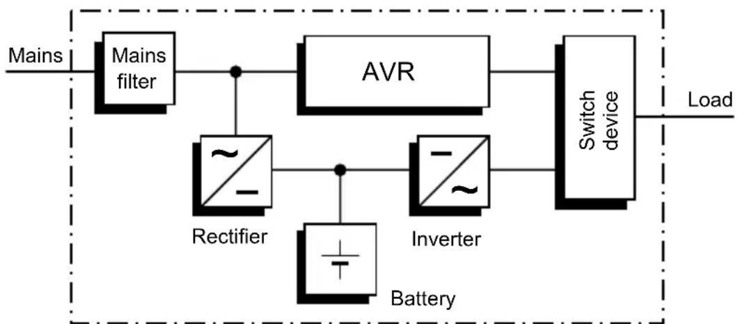
flowchart
graph LR
    A["Mains"] --> B["Mains filter"]
    B --> C["AVR"]
    C --> D["Switch device"]
    D --> E["Load"]
    C --> F["Rectifier"]
    C --> G["Inverter"]
    F --> H["Battery"]
    G --> H
Block diagram of UPS PROTECT B. PRO
If a mains failure occurs, the switch device is activated. At this point, the inverter takes over the supply of power to the connected electrical loads to avoid the risk of data loss or electrical load damage. The PROTECT B.PRO continues to provide power until the battery is discharged or until your IT system is properly shut down and switched off.
This autonomy time is largely dependent on the connected electrical load value. When the mains supply exhibits normal values again, the UPS switches the electrical load back to the mains. The battery charge rectifier then recharges the battery.
If a mains failure occurs, the mains input into the device is disconnected via both poles for safety reasons (VDE, German Association for Electrical, Electronic & Information Technologies). This securely prevents feeding back into the mains and live voltage on the poles of the power plug.
Additional measures also ensure effective protection of the data/network interface.
2.3 Technical data
Type rating
| PROTECT B. 750 PRO | 750 VA (cos φ = 0.9 lag.)675 W |
| PROTECT B. 1000 PRO | 1000 VA (cos φ = 0.9 lag.)900 W |
| PROTECT B. 1400 PRO | 1400 VA (cos φ = 0.9 lag.)1260 W |
| PROTECT B. 1800 PRO | 1800 VA (cos φ = 0.9 lag.)1620 W |
| PROTECT B. 2300 PRO | 2300 VA (cos φ = 0.9 lag.)2070 W |
| PROTECT B. 3000 PRO | 3000 VA (cos φ = 0.9 lag.)2700 W |
| UPSinput | 1ph~/N/PE |
Rated supply voltage 220/230/240 Vac
Voltage range without battery ±20%
Frequency (automatic detection) 50 /60 Hz ±5 Hz
Current consumption at 230 Vac, full load and battery charge (max.)
PROTECT B.750 PRO 4.0 A
PROTECT B.1000 PRO 5.3 A
PROTECT B.1400 PRO 7.3 A
PROTECT B.1800 PRO 11.2 A
PROTECT B.2300 PRO 11.8 A
PROTECT B.3000 PRO 15.2 A
Connection Plug acc. to IEC 320
UPS output
| Rated output voltage 220/230/240 Vac ±10%(in ECO & AVRange) | 208 Vac with 20%power reduction |
| Rated output voltagetolerance in battery mode ±3% | |
| Frequency in battery mode 50/60 | Hz ±1 Hz |
Rated output current (at 230 V AC)
PROTECT B.750 PRO 3.2 A
PROTECT B.1000 PRO 4.3 A
PROTECT B.1400 PRO 6.1 A
PROTECT B.1800 PRO 7.8 A
PROTECT B.2300 PRO 10.0 A
PROTECT B.3000 PRO 13.0 A
Power factor range 0.8
lag. to 0.9 cap.
with full power output
10% power reduction in the
range of 0.5 lag. to 0.8 lag.
Transfer time in case of mains failure 2-6 ms (typical), 8 ms max.
Voltage waveform Sinusoidal, distortion
< 5% THD (linear load)
< 10% THD (non-linear load)
Connection sockets acc. to IEC 320
Overload capacity in mains mode ≤ 120% for 5 min
120% - ≤150% for 10 s
150% for 1 s
in battery mode ≤ 110% for 1 min
110% - ≤150% for 10 s
150% - ≤200% for 500 ms
200% for 150ms
Battery
| Coupled battery modules | Autonomy times (rated load, cos φ = 0.9 lag.) with 100% charged battery and at 25 °C | |||||
| 750 VA | 1000 VA | 1400 VA | 1800 VA | 2300 VA | 3000 VA | |
| with integrated battery system | 3.5 min. | 3.5 min. | 5 min. | --- | 3.5 min. | 4 min. |
| with 1 ancillary battery unit | --- | --- | --- | 10 min. | --- | --- |
| with 2 ancillary battery units | --- | --- | --- | 26 min. | --- | --- |
| with 3 ancillary battery units | --- | --- | --- | 44 min. | --- | --- |
| with 4 ancillary battery units | --- | --- | --- | 60 min. | --- | --- |
Deep discharge protection/ Yes
Protection against overcharging
Rated direct current (intermediate circuit)
Trickle charge voltage 2.28 Vdc/cell (25 °C preset)
Temperature-dependent charge voltage
Battery charge current 1.2 Adc (models with integ. battery)
(max.) 4 Adc or 8 Adc (PROTECT B.1800 PRO)
Battery type Sealed lead-acid battery (VRLA)
branded
product
PROTECT B.750 PRO 2 blocks of 12 V 7 Ah each
PROTECT B. 1000 PRO 2 blocks of 12 V 9 Ah each
PROTECT B.1400 PRO 4 blocks of 12 V 7 Ah each
PROTECT B. 1800 BP 2 banks/4 blocks of 12V 9Ah each
PROTECT B.2300 PRO 6 blocks of 12 V 7 Ah each
PROTECT B.3000 PRO 6 blocks of 12 V 9 Ah each
Recharge times \~ 6h to 90% with internal battery
\~ 4h / 6h ( 4Adc ) / \~ 4h / 6h ( 8 Adc ) with 1/2/3/4 battery expansion(s)
Communication
| Interfaces | RS232 (SUB-D (9-pole)), LAdditionally: Communication slot for expansions (e.g. relay card / SNMP mini etc.) |
| Remote switch-off contact | Floating (NC contact) |
| Shutdown software on CD | "CompuWatch" for all common operating systems, e.g. Windows, Linux, Mac, Unix, Novell, Sun |
General data
| Classification | VI SS 211 as per IEC 62040-3Line-interactive technology |
| Efficiency | B.750 PRO | >97% / >90% / >83% |
| with a 50-100% load B. | 1000 PRO | >97% / >90% / >83% |
| (ECO / AVR / battery mode) B. | 1400 PRO | >97% / >90% / >85% |
| B. | 1800 PRO | >97% / >90% / >85% |
| B.2300 PRO | >97% / >90% / >87% | |
| B. | 3000 PRO | >97% / >90% / >87% |
Inherent noise (at 1m distance)
| PROTECT B.750-B.3000 | ≤40 dB(A) in mains mode (ECO) and load < 70% |
| PROTECT B.750-B.1800 | ≤45 dB(A) | in mains mode and load >70% |
| PROTECT B.2300-B.3000 | ≤55 dB(A) |
| PROTECT B.750-B.1000 | ≤45 dB(A) |
| PROTECT B.1400-B.3000 | ≤55 dB(A) |
| Cooling type | External cooling via variable-speed | fan |
| Operating temperature range 0 °C to +40 °CRecommended: +15 °C to +25 °C(depends on battery system) |
| Storage temperature range | -20 °C to +50 °C |
| Humidity ≤ | 90% (without condensation) |
| Set-up altitude | Up to 1,000 m at rated power |
| Up to 2,000 | m with 10%}power |
| Up to 3,000 | m with 20%}reduct. |
| Max. transport altitude: 10,000 m |
Connections
| Mains connection | IEC320 C14 (B.750-B.1800) |
| IEC320 C20 (B.2300-B.3000) |
Electrical load connections
| PROTECT B.750-B.1800 4 x IEC320 C13 (UPS-direct) |
| 4 x IEC320 C13 (manageable) |
| PROTECT B.2300 -B.3000 3 x IEC320 C13 (UPS-direct) |
| 1 x IEC320 C19 (UPS-direct) |
| 3 x IEC320 C13 (manageable) |
| Display | Liquid crystal displayAdditional 3 LEDs for operating display |
| Housing colour | Blackline, silver front |
Weight (net/gross)
PROTECT B.750 PRO 14.5 kg/18.0 kg
PROTECT B. 1000 PRO 15.0 kg/18.5 kg
PROTECT B.1400 PRO 22.0 kg/25.5 kg
PROTECT B. 1800 PRO 14.5 kg/18.0 kg
PROTECT B. 1800 BP PRO 29.5 kg/32.5 kg
PROTECT B.2300 PRO 29.0 kg/33.5 kg
PROTECT B.3000 PRO 29.5 kg/34.0 kg
Dimensions (WxDxH - net)
(Specifications include front panel from horizontal viewpoint)
B.750 PRO/B.1000 PRO 445 mm x 420 mm x 88 mm
B. 1400 PRO/B. 1800 (BP) PRO 445 mm x 520 mm x 88 mm
B. 2300 PRO/B. 3000 PRO 445 mm x 640 mm x 88 mm
Together with the mounting brackets, a standardised rack installation dimension of 19"=482.6 mm in exhibited. Height of the drawer: 2U.
Dimensions (WxDxH – gross (incl. packing materials))
B.750 PRO/B.1000 PRO 606 mm x 505 mm x 245 mm
B.1400 PRO/B.1800 (BP) PRO 706 mm x 572 mm x 245 mm
B.2300 PRO/B.3000 PRO 765 mm x 607 mm x 245 mm
Guidelines
The PROTECT B. PRO complies with product standard EN 62040.
The CE mark on the device confirms compliance with EC Low-Voltage Directive 2006/95/EC and EMC Directive 2004/108/EC for electromagnetic compatibility if the installation instructions in the operating instructions are followed.
For 2006/95/EC Low-Voltage Directive
Reference no. EN 62040-1-1: 2003
For 2004/108/EC EMC Directive
Reference no. EN 62040-2: 2006
EN 61000-3-2: 2006 + A1: 2009 + A2: 2009
EN 61000-3-3: 2008

WARNING:
This is a category C2-UPS product. In a domestic environment, this product may cause radio interference, in which case the user may be required to take additional measures.
3 Safety Regulations
3.1 General safety precautions
Read these operating instructions before commissioning the USV PROTECT B.PRO for the first time and comply with the safety precautions!
The device may only be used in technically fault-free condition, as intended and in a safety-conscious manner in compliance with the operating instructions! Eliminate malfunctions immediately if they could potentially compromise safety.
The following pictograms for danger and important information are used in these instructions:

Danger!
In case of danger to life and limb of the operator.

Attention!
In case of risk of injury or danger to the device and device parts.

Information!
Useful and important information on the operation of the UPS.
3.2 Safety precautions for PROTECT B.PRO
This chapter contains important instructions for the UPS PROTECT B. PRO which must be followed during installation, operation and servicing of the uninterruptible power supply and the batteries.

The UPS is energised with voltage which is potentially dangerous. The device may only be opened by trained professional personnel. Repairs may only be made by qualified customer service employees!
The output can be energised even if the UPS is not connected to the mains supply, as the UPS has its own internal power supply (battery)!
For reasons of personal protection, the device must be properly earthed!
The PROTECT B.PRO may only be connected to 220/230/240 V AC mains with protective earthing with a VDE-tested mains connection cable with protective earthing conductor (included in the scope of supply).
Risk of burns!

The battery exhibits high short-circuit currents. Incorrect connection or errors made while disconnecting can cause the melting of plug connections, flying sparks and severe burns!

The device is equipped with a warning signal that is emitted if the battery power of the PROTECT B. PRO has run out or if the UPS is not operating in its normal condition.

For continuous operating safety and safe working with the UPS, heed the following safety precautions:
- Do not take the UPS apart!
(The UPS does not contain any parts which require regular servicing. If you open the device, the warranty will become null and void!) - Do not set up the device in direct sunlight or near heat sources!
- The device was intended to be set up in heated indoor rooms. Do not set up the UPS near water or in overly humid environments!
- If the UPS is brought from a cold environment into the room where it will be set up, condensation may occur. In such cases, allow the device to acclimatise for at least 2 hours.
The UPS must be completely dry before it may be commissioned.
- Never connect the mains input and UPS output to one another!
- Ensure that liquids or foreign bodies do not end up in the UPS!
- Do not block the ventilation openings of the device! Ensure that children do not insert objects into the ventilation openings!
- Do not connect household appliances, such as hair driers, to the UPS! Also use caution when operating with loads involving motors. Feeding back into the inverter, e.g. due to brief generator operation of the load, must absolutely be avoided.
- The mains connection should be located near the device and easily accessible so as to make disconnection of the AC input or of the plug easier!
- Do not unplug the mains connection cable from the UPS or the building installation socket (safety socket) during operation, as the protective earthing of the UPS and all connected electrical loads will be nullified.
Risk of electric shock!
The components inside the UPS are still connected to the battery even after the mains voltage is disconnected and can therefore cause electric shocks. For this reason, the battery circuit must absolutely be broken before service or maintenance work may be carried out!
Battery replacement and service must be carried out, or at least monitored, by a professional who has experience with batteries and the required precautionary measures!
Keep unauthorised persons away from the batteries!
When replacing the batteries, heed the following:
Use only identical, maintenance-free, closed lead batteries with the same specifications as the original batteries. Pre-wired replacement battery kits which are ready for connection are available at your specialist dealer.
Risk of explosion!
Do not throw batteries into an open fire. Do not open or damage batteries (released electrolyte can damage skin and eyes and can be poisonous!)
Batteries can cause electric shocks and exhibit high short-circuit currents.
For this reason, implement the following precautionary measures when working with batteries:
- Remove watches, rings and any other metal objects!
- Use only tools with insulated handles!

To avoid switch-on current spikes, do not use connecting blocks with central on/off switches.
Switch the UPS "OFF" if it will not be used for a longer period of time. If the mains at your company's facility are switched off every night, the PROTECT B. PRO must be switched off every evening. Otherwise, the battery will discharge. Frequently occurring full discharging of the battery should be avoided to extend its service life!

For your personal safety, never switch the UPS on if the mains plug of the PROTECT B. PRO is unplugged!
3.3 CE certificate
AEG
Power Solutions
Declaration of Conformity
Document - No. CE 0195
We
declare under our sole responsibility that the product
Uninterruptible Power Supply (UPS)
Protect B. PRO
Type Power 750VA, 1000VA, 1400VA,
1800VA, 2300VA, 3000VA
to which this declaration relates is in conformity with the following standards or other normative documents:
EN 62040-2:2006 Class C2
EN 61000-3-2:2006+A1:2009+A2:2009
EN 61000-3-3:2008
EN 62040-1-1:2003
Following the provisions of directives
2004 / 108 / EC
EMC- Directive
2006/95/EC
Low Voltage Directive
Year of labeling the CE-Mark:2010
59581 Warstein, 16.11.2010
AEG Power Solutions GmbH Quality Management

(Kirchhoff)
4.1 Unpacking and checking
The device has been fully tested and checked. Although the packing and shipping of the device are done with the usual care, transport damage cannot be fully ruled out.

Transport damage claims are to be lodged with the transport company!
For this reason check the shipping container for damage upon receipt. If necessary, ask the transport company to check the goods and record the damage in the presence of the transport company employee. Report the damage via the AEG representative/dealer within 8 days of delivery.
Check the contents of the delivery for completeness:
• PROTECT BPRO
with 750, 1000, 1400, 1800, 2300 or 3000 VA
- 2 base feet and 2 mounting brackets incl. installation hardware (screws)
- 2 mains connection cables
(1x hybrid plug as per CEE 7/7 / 1x plug as per BS1363)
- 2 device connection cables of type IEC320 10A
Additionally, 1 device connection cable of type IEC320 16A with PROTECT B.2300 PRO and PROTECT B.3000 PRO
• 2 communication cables (USB & RS232)
- Management software "CompuWatch" on CD
- Safety and operating instructions
External battery modules include the following with delivery:
• External battery unit PROTECT B. 1800 BP PRO
- Base foot expansion and 2 mounting brackets incl. installation hardware (screws)
- Special battery connection cable and detection cable
- Safety instructions
Please report any deviations to our hotline (see Page 5).
The original packing materials provide effective protection against impacts and should be retained to ensure secure transport at a later date.
To rule out the risk of suffocation, keep the plastic packaging bags out of the reach of babies and children.

Handle the components with care. Be especially mindful of their weight. Obtain the help of another person when moving the PROTECT B. 2300 PRO, the PROTECT B. 3000 PRO and the external battery unit PROTECT B. 1800 BP PRO.
4.2 Set-up location
The PROTECT B. PRO was designed to be set up in a protected environment. When setting up the device, take factors such as sufficient ventilation and appropriate ambient conditions into consideration.
- The installation site must be sufficiently strong and stable to avoid vibrations and impacts.
- Ensure sufficient load-bearing capacity, especially when used together with external battery units (special accessories).
- Position the devices in such a way that sufficient air circulation is ensured. There must be at least 100 mm clearance behind the back fan for ventilation purposes. Do not block supply air openings on the front. A clearance of 50 mm must be ensured here.
- Position external battery units directly next to the UPS system. To preserve maximum mechanical stability in case of rack installation, place each drawer on its own pair of rack rails.
-
Avoid extreme temperatures! To maximise the service life of the batteries, we recommend an ambient temperature of 15^ C to 25^ C. Do not expose the devices to direct sunlight or operate them near other heat sources, e.g. radiators.
-
Protect units against external influences (particularly humidity and dust). In this regard, observe the information in Chap3 as from Page16 of these operating instructions.
- If the device is brought from a cold room to a warm room, or if the room temperature drops suddenly, condensation may occur inside the device. Let the device sit for 2 hours before turning it on to avoid the formation of condensation.
- Ensure that no magnetic storage media are stored and/or used near the PROTECT B. PRO.

Check on the rating plate whether the voltage and frequency specifications match the values applicable for your electrical loads.
4.3 Installation
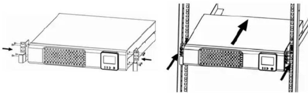
4.3.1 Installation in a 19" rack
Install the drawers from your network cabinet manufacturer or the optional UPS rack rails from the AEG product line, preferably in the lower third of the cabinet. Take the cabinet's centre of gravity and sufficient fresh air supply into consideration here.
Before inserting the device or the external battery unit into the network cabinet, attach the side mounting brackets included with the delivery beforehand.
Step 1: Step 2:
natural_image
Technical line drawing of a server rack with two panels, showing front and side views (no text or symbols)4.3.2 Set-up as an upright device (tower)
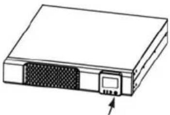
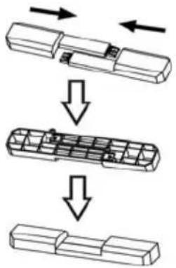
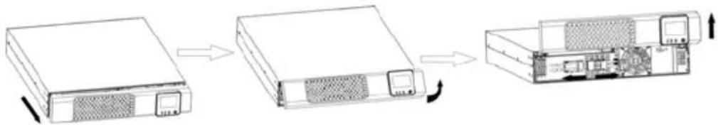
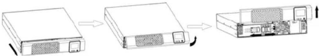
Step 1: Step 2: Step 3:
Press the round button located at the bottom right. The display is released from the retainer.
Rotate the display clockwise by 90°.
Press the display back into its retainer in the position shown below.
natural_image
Line drawing of a rectangular electronic device with a central display and an arrow pointing to it (no text or symbols)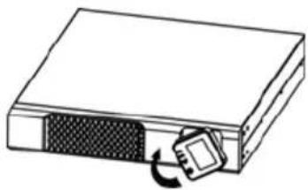
natural_image
Simple line drawing of a rectangular electronic device with a button and scroll, no text or symbols present.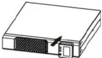
natural_image
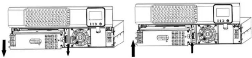
Simple line drawing of a rectangular electronic device with a textured cover and an arrow pointing to its side (no text or symbols)Step 4: Step 5: Step 6:
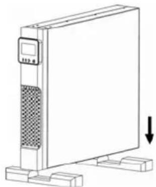
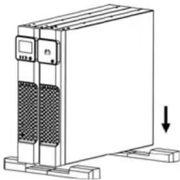
Assemble the feet as shown below.
Position UPS into the feet, which have already been installed.
Position the feet in the front and rear third.
flowchart
graph TD
    A["Top Component"] --> B["Bottom Component"]
    B --> C["Bottom Left Arrow"]
    B --> D["Bottom Right Arrow"]
natural_image
Line drawing of a server rack unit with a downward arrow indicating compression or cooling (no text or symbols present)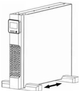
natural_image
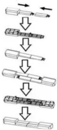
Technical line drawing of a mechanical device with a control panel and directional arrows indicating movement (no text or symbols)... Set-up of the UPS in connection with an external battery unit
flowchart
graph TD
    A["Raw Material Input"] --> B["Process Step 1"]
    B --> C["Process Step 2"]
    C --> D["Product Output"]
    D --> E["Final Product"]
natural_image
Line drawing of a server rack unit with cooling fins and a downward arrow indicating cooling (no text or symbols)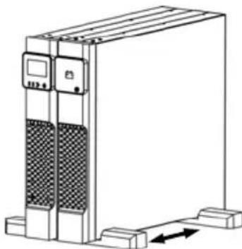
natural_image
Line drawing of a server rack unit with control panel and directional arrows indicating movement (no text or symbols)Finally, carefully lift the name plates at the side at the end of the lettering, turn them and engage them in the pre-drilled second position.
5 Overview of Connections, Controls and Display Components
5.1 Front view
UPS of the PROTECT B. PRO series
Ext. battery expansion (BatteryPack) PROTECT B.1800BP PRO
Explanations:
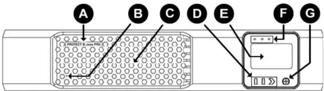
A UPS model series designation with power specification in VA
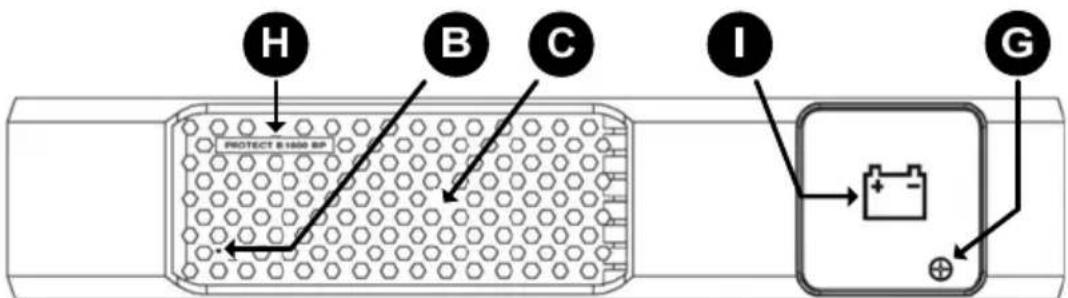
B Hole for attachment of the name plate for tower setup
C Ventilation grate (do not block)

Except for the PROTECT B.1800PRO (which has an external battery system), the connections of the integrated battery unit are located behind the respective front panels.
D Operating buttons for menu navigation
E Liquid crystal display with pictograms
F Status display (LEDs of different colours)
G Button for mechanical unlocking of the operator panel
H Designation of the external battery expansion
I Panel with battery symbol as identification of the battery unit
5.2 Rear view (connections)
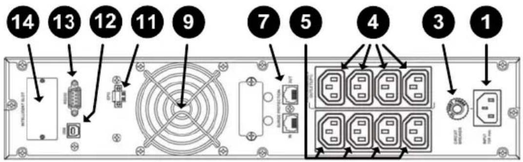
Rear view of PROTECT B.750 PRO/B.1000 PRO/B.1400 PRO
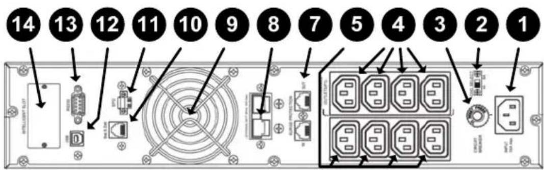
Rear view of PROTECT B.1800 PRO
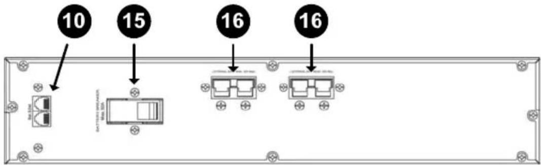
Rear view of PROTECT B.1800 BP PRO
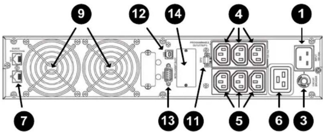
Rear view of PROTECT B.2300 PRO/B.3000 PRO
Explanations:
1 Mains connection (UPS input)
2 Sliding switch for selecting the maximum battery charge current (PROTECT B.1800 PRO only)
3 Resettable mains input automatic fuse
4 Manageable UPS outputs, i.e. electrical load connections which can be influenced via the UPS operator panel and/or the software
5 Electrical load connections (UPS outputs) for critical loads with the highest priority, continuously supplied directly from the UPS (not manageable)
6 Electrical load connection with the option of full power consumption via a UPS outlet IEC socket (PROTECT B.2300 PRO and PROTECT B.3000 PRO only)
7 Overvoltage protection module for data cables (telephone, fax, modem or network (RJ11/RJ45 10/100 Mbit/s)
8 Connection for external battery unit (PROTECT B.1800 PRO only; covered upon delivery)
9 Fan (Attention: Maintain a minimum clearance of 100 mm behind the fan for unobstructed air output)
10 Jack(s) for automatic external battery detection (PROTECT B.1800 (BP) PRO only)
11 Emergency Power Off contact
12 USB communication interface
13 RS232 communication interface (Sub-D9 jack)
14 Communication slot for optional expansion cards: relay card, SNMP etc. (shown here with cover)

The USB and RS232 communication interfaces are mutually exclusive, i.e. either USB or RS232 is used. The communication slot, on the other hand, is dual monitor capable, i.e. it can be used alongside the USB or RS232 interface.
15 Battery automatic fuse (PROTECT B.1800 BP PRO only)
16 Attachment socket for external battery unit for connection with the UPS or another battery unit (covered upon delivery - PROTECT B.1800 BP PRO only)
6 Electrical Connection
6.1 Internal battery contact connection (all models except PROTECT B.1800PRO)
-
Ensure that the UPS is de-energised and that no mains connection cables are plugged in.
-
Now grasp the left and right sides below the front panel and pull the front panel out toward the front. The lock will disengage...
-
...and you can swivel the entire front section upward. Do not disconnect the ribbon cable to the liquid crystal display! The mechanical parts must be handled without the use of great force.
-
Now connect the internal battery system by connecting the two battery connectors to one another.
flowchart
graph LR
    A["Front Panel"] --> B["Internal Storage Unit"]
    B --> C["Internal Storage Unit with Component 1"]

When making the connection, make sure that you attach the plugs quickly and securely into one another. Any minor electric arcing that may occur when doing so is insignificant.
- Then slowly close the front panel using appropriate caution in the reverse order. Make sure that you don't pinch any cables; always handle the front panel with both hands (applying even force on the left and right). Continue with Section 6.3, starting on Page 30.
flowchart
graph LR
    A["Internal Component"] --> B["Storage Unit"]
    B --> C["Final Storage Unit"]
6.2 External battery unit contact connection (PROTECT B.1800 PRO only)
External battery expansions are connected from the back of the device. It is not necessary to open the front panel(s).
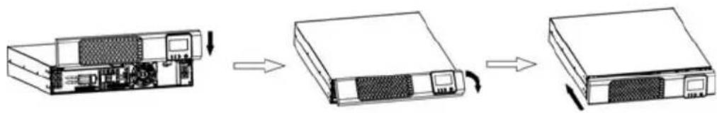
Remove the battery connection covers from the back of the UPS and the battery unit(s) (see also Item 8/16 on Page 26). Make the power connections to the battery using the special battery cable included with delivery according to the diagram shown below. Begin with contact connection of the UPS to the first battery unit. Then connect any additional battery units as shown. At the last battery unit, cover the unused battery socket.

When making the connections, ensure that the battery plug is securely and fully inserted into the counter piece.
The next step involves the included data cables with the small transparent RJ11 plugs. They are used for automatic detection of the battery units. As shown in the figure, connect the UPS to the first battery unit and then (if additional battery units are to be present) battery unit to battery unit.
flowchart
graph TD
    A["Server Rack"] --> B["Module 1"]
    A --> C["Module 2"]
    A --> D["Module 3"]
    A --> E["Module 4"]
    A --> F["Module 5"]
    A --> G["Module 6"]
    A --> H["Module 7"]
    A --> I["Module 8"]
    A --> J["Module 9"]
    A --> K["Module 10"]
    A --> L["Module 11"]
    A --> M["Module 12"]
    A --> N["Module 13"]
    A --> O["Module 14"]
    A --> P["Module 15"]
    A --> Q["Module 16"]
    A --> R["Module 17"]
    A --> S["Module 18"]
    A --> T["Module 19"]
    A --> U["Module 20"]
Now move the small sliding switch "CHG. SELECT" (Item 2 on Page 26) to the corresponding position. If using a maximum of two battery units, set it to "4A"; if using three or four battery units, set it to "8A".
Then actuate the fuse(s) on the back of the battery unit(s) (Item 15 on Page 26). Move the small lever/s to the "ON" position.
6.3 Mains connection
Compare the setting of the rated supply voltage of the UPS to the rated voltage applicable for your country. The ex-works presetting of the UPS output voltage is 230 V AC. Changes to 208 V AC, 220 V AC, 230 V AC or 240 V AC can be made via the operator panel.
To ensure proper functioning of the UPS and its additional equipment, it is necessary to provide the mains supply cable with an appropriate back-up fuse. With all models of the PROTECT B. PRO series, connection is carried out using the included mains connection cable to a conventional safety socket. Ensure sufficient power rating of the fuse in your subdistribution. The more powerful models as from PROTECT B.1800 PRO, in particular, require their own 16 A fuse protection. Do not yet plug the safety plug of the mains connection cable into the intended safety socket.
6.4 Electrical load connection
Before connecting the electrical loads to the UPS, please check whether the specified rated output on the rating plate is greater than or equal to the total electrical load output.
Connect the intended electrical loads to the outlets of your UPS. Use the included electrical load connection cables for this purpose. Pay attention to the sub-division of the output sockets here (see also Section 5.2 on Page 26). Important electrical loads which must be powered continuously should be connected to continuously energised outputs. The manageable output circuit is used for electrical load segmentation. You will leave your electrical loads switched off at first. Should additional electrical load connection cables be required, please contact your specialist dealer.

If a shared distribution cabinet is used (circuits with both mains and UPS power), label each circuit with the respective feed (mains or UPS).
Finally, check the firm seating of the wire jumpers attached in the Emergency Power Off plug and tighten the two external screws of the plug part (see also Page27 Item 11).
If you would like to use the emergency switch-off function, continue with Section 8.4 on Page 41.

The integrated Emergency Power Off mechanism is used solely to switch off the UPS power. This is done electronically and does not correspond to an EMERGENCY-STOP device as per DIN EN ISO 13850.
7 Operation and Control
7.1 Initial commissioning
Plug the safety plug of the mains connection cable into the intended, properly fuse-protected safety socket. The UPS is automatically supplied with power from the public mains. The UPS starts up in the initialisation phase. All pictograms and LEDs of the liquid crystal display light up briefly.

If an error indication is received, analyse the display using the overview in Chapter 9, starting on Page 43. If the battery system is not recognised, for example, go back to Chapter 6, starting on Page 28.
The ex-works presetting of the rated output voltage is 230 V. The changing of this parameter is described in Section 7.4 on Page 38.
7.1.1 Switching ON the UPS
If the UPS is in the so-called standby mode (e.g. after the procedures described above), press and hold the "ON/MUTE" button (for about 3 seconds) until the "ON" message appears at the top right of the display. The UPS carries out a brief self-test and begins normal operation after a few seconds. The display switches to the UPS statusdisplay. The "OK" message appears at the top right.
Now switch on your electrical loads one after another. The device load of the UPS should not exceed the specified rated load of the
UPS device at any time. If the device does become overloaded, however, "OVERLOAD" appears in the display and an audible tone is emitted. The connected electrical loads continue to be supplied with power for a specific period of time which depends on the severity of the overload, but the connected load must be reduced immediately.
Not heeding the "device overload" condition can lead to a complete failure of all UPS functions!
Also avoid brief device overloads, e.g. as can occur when connecting a laser printer or a laser fax machine. Do not connect household appliances or machine tools to the UPS.

Never connect or switch on additional electrical loads to the UPS if a mains failure is in effect. The UPS is operating on emergency power!
In general, overloads should not occur in battery mode if they do not occur in normal mode.

If the red "FAULT" LED lights up and an audible tone is emitted, a switching-off malfunction is in effect. Follow the instructions in Chapter 9, starting on Page 43.
7.1.2 Switching OFF the UPS
If the UPS is in operation, it can be switched off by pressing and holding the "OFF" button for approx. 2 seconds. The power supply is interrupted immediately, i.e. all electrical loads connected to the UPS are switched off.
7.2 Operator panel
7.2.1 Overview
The panel is made up of three units: the liquid crystal display with black pictograms on a white background, the four buttons for menu navigation and mechanical enabling of the rotatable unit and, at the top, the three different UPS status display LEDs.
7.2.2 Operating buttons (navigation)
The four buttons possess the following functions:
| ON/MUTE □▼ | Switching on the device from the standby operating mode (press and hold the button for approx. 3 seconds for this purpose)Deactivation of the audible alarm in battery mode (press and hold the button approx. 5 seconds for this purpose; this does not affect the warning or fault indications)Activation of the self-test function in the normal operating condition (press and hold the button for approx. 5 seconds for this purpose)Navigation in the setup menu |
| SELECT □▲ | Switching of the measured value display: input volt./input frequency/battery voltage/output voltage /output frequency/load-/UPS internal temperature/number of externally connected battery systems (press button briefly to change display)Calling up the UPS setup menu from standby mode, i.e. UPS (press and hold the button for approx. 5 seconds for this purpose)Navigation in the setup menu |
| OFF ➕ ENTER | Switching off the device/the electrical loads from the normal operating mode (press and hold the button for approx. 3 seconds for this purpose)Confirmation function within the UPS setup menu |

- This button is used to release the mechanical lock of the operator panel and thus permits the set-up-based display direction (rack or tower mode)
7.2.3 Indicators (LED indicators)
| LED | Name | Function |
| Green | Power On | Power supply of the control unit is live, i.e. LED lights up in standby mode and in mains and battery modes |
| Yellow | Batt.mode | LED lights up during battery mode |
| Red Fault Malfunction | ON LED (see also Chapter 9, starting on Page 43) | |
7.2.4 Liquid crystal display
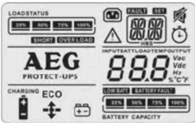
| Information on the remaining autonomy time | |
 | Symbol for display of the autonomy time |
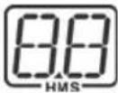 | Shows the remaining autonomy time, depending on the load, in hours (H), minutes (M) and seconds (S) until the battery undervoltage threshold is reached |
| Information with warnings and fault messages | |
 | Symbol as an indicator for a warning |
| FAULT | Symbol as an indicator for a fault message |
 | Display of the warning or fault code (for details, see also Section 9.1.1 on Page 43) |
| Setup options | |
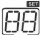 | Indicator in setup menu(see also Section 7.4, starting on Page 38) |
| Displayed measured values | |
INPUTBATTLOADTEMPOUTPUT  Vac Vdc Hz %°C°F Vac Vdc Hz %°C°F | The measured values for the following are displayed in sequence: Input voltage [V AC], input frequency [Hz], battery voltage [V DC], output voltage [V AC], output frequency [Hz], load [%] and internal UPS/battery temp. [°C] |
RATT  | Indicator for the number of externally connected battery units (here, none = "00") |
| Information on the UPS load (electrical load value) | |
LOADSTATUS  | Bar graph for indication of the UPS load: 0-25%, 26-50%, 51-75% and 76-100% |
 | Indication of an active overload |
 | Indication of an electrical load short-circuit |
| UPS status | |
 | Status indication of the manageable output sockets. Symbol is active, i.e. lights up with energised output circuit |
 | Pictogram for signaling the silenced internal signaller |
 | Automatic efficiency-optimised operation (internal UPS buck & boost levels deactivated) |
CHARGING  | Battery symbol indicates an active battery charger; "CHARGING" flashes with active battery boost charging |
 | Indicates an active AVR (voltage regul.) (internal UPS buck or boost level activated) |
 | Pictogram indicates an active battery discharge, e.g. in case of a mains failure or during the UPS self-test |
| Information on the battery system | |
 BATTERY CAPACITY BATTERY CAPACITY | Bar graph for displaying the battery capacity: 0-25%, 26-50%, 51-75% and 76-100% |
| LOW BATT. | Battery undervoltage indication |
| BATTERY FAULT | Pictogram indicates a faulty/non-connected battery system |
7.2.5 Abbreviation index
| Abbreviation | Display Meaning | |
| ENA | ENA | Enable |
| DIS | DIS | Disable |
| ESC | ESC | Escape |
| EP | EP | Emergency Power Off |
| TP | TP | Temperature |
| CH | CH | Charger |
7.2.6 Audible signals
| Battery mode Periodic warning tone every 4 seconds | |
| Battery undervolt. | Periodic warning tone every second |
| Replace battery | Periodic warning tone every 2 seconds |
| Overload Double | periodic warning tone every second |
| Fault Continuous | warning tone |
Audible signals in conjunction with pictograms as fault indications can be found with detailed descriptions in Chapter 9, starting on Page 43.
7.3 UPS operating states
| Mains mode ECO mode | Abbreviation for "Efficiency Corrective Optimiser"In this operating mode (UPS input voltage below ±10% of U_rated ), the electrical loads are switched to direct mains supply to increase efficiency. With a fully-charged battery system, the UPS internal fan also stops. | 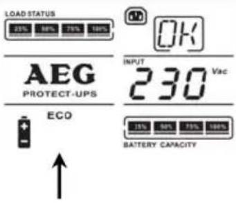 |
| Mains mode AVR mode | If the UPS input voltage is outside the ECO range, but within the voltage window accepted by the UPS, automatic voltage regulation (AVR) is activated. | 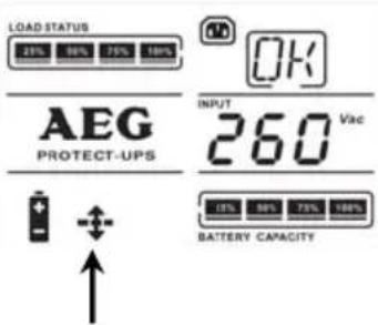 |
| Battery mode | If the UPS input voltage lies outside the specified tolerance, e.g. in case of a mains failure, the UPS switches to battery mode. In addition, a periodic warning tone is emitted every 4 seconds. | 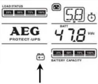 |
| Standby operating mode | UPS is supplied with voltage, but is switched off (electrical loads not powered). Battery charger, on the other hand, is ready for operation in standby mode. The battery is thus being charged. | 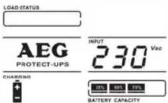 |
7.4 UPS settings
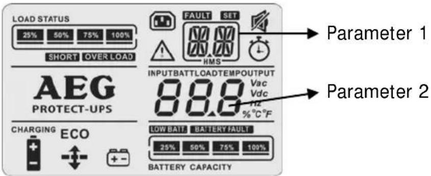
The two parameters of the UPS setup menu:
Parameter 1: displays the currently selected menu item. 3 settings can be changed manually via the operator panel: UPS output voltage "01", activation or deactivation of a time-based manageable output socket group "02" and its delay "03". The UPS setup menu can be exited via "00" (ESCAPE).
Parameter 2: displays the currently selected setting.
• 01: Setting of the UPS output voltage
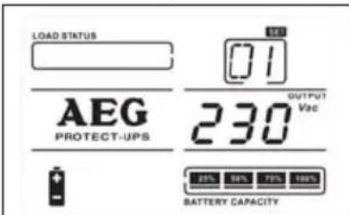
208: Rated output voltage = 208 V AC
220: Rated output voltage = 220 V AC
230: Rated output voltage = 230 V AC (ex-works presetting)
240: Rated output voltage = 240 V AC
• 02: Setting of the manageable UPS outputs (active/inactive)
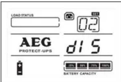
ENA: Time-based influencing of the outlet sockets allowed (enabled)
DIS: Influence deactivated (disabled) (ex-works presetting)
Note: With "DIS", all output sockets function identically!
• 03: Setting of the time-based switch-off delay in minutes
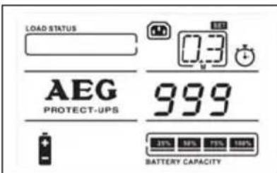
Specifies the switch-off time of the manageable UPS outputs in battery mode with a previously active setting of "02".
The setting is made in minutes (ex works presetting: "999" minutes)
• 00: Exit the UPS setup menu
Procedure for programming the manageable outputs
| Step 1:First set the UPS to the so-called standby operating mode, i.e. if the UPS was just in operation, switch it off. ATTENTION: Your connected electrical loads are de-energised by this! Also ensure that the internal/external battery's contacts were connected properly. The liquid crystal display should generally show the content shown here. |  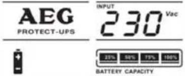 |
| Step 2:You can access the UPS setup menu by pressing and holding the "SELECT" button for at least 5 seconds. "01" appears in the "SET" display window. | 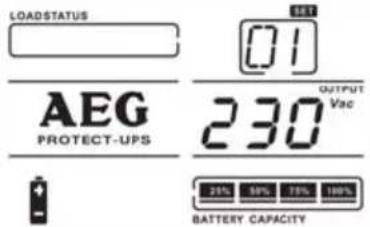 |
| Step 3:Navigate to menu item "02" with the "▼" or "▲" button. Now confirm with the "ENTER" button. You will be brought to the selection window of parameter 2: Select between "dis"able and "ena"ble here. Then press either the "▼" or "▲" button again and select "ena"ble. Confirm your selection with "ENTER". | 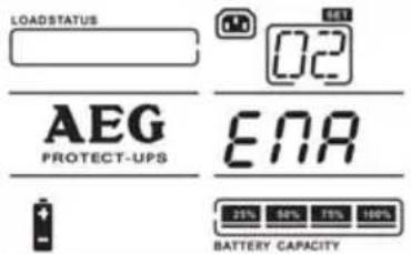 |
| Step 4:Now navigate to menu item "03" with the "▼" or "▲" button. After confirming with "ENTER" again, you can now specify the setting of the desired switch-off time in minutes in battery mode ("▼"or"▲"). Finally, confirm with "ENTER" once again. | 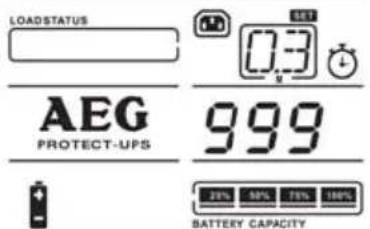 |
| Step 5:Setup is now complete. You can exit the setup menu by selecting menu item "00", i.e. navigate to "00" with "▼" or "▲", and confirm again with the "ENTER" button. The liquid crystal display should now in principle correspond with the display from Step 1 again. | |
| Step 6:Disconnecting the UPS from the mains will then save the changes to the UPS internal memory. Wait until the liquid crystal display goes out. | |
8 Interfaces and Communication
8.1 Computer interfaces RS232 and USB
Different interfaces are available for control of the UPS and the convenient read-out of status indications and measured values. The interface protocol is designed for operation with the shutdown and UPS management software "CompuWatch" from AEG. To connect your UPS to the PC, use the RS232 or USB communication cable included with the delivery.

The USB and RS232 communication interfaces are mutually exclusive, i.e. either USB or RS232 is used. Assignment of the RS232 Sub-D9 jack: 2 = TxD; 3 = RxD; 5 = GND
8.2 Communication slot
The back of the UPS also features a cover (see item 14 on page 27), the removal of which allows the installation of optionally available communication components, e.g.:
Relay card: Plug-in card with status indications, implemented via floating relay contacts (NC or NO contacts)
SNMP card: Plug-in card for direct integration of the UPS into the Ethernet network via RJ45 (TCP/IP) and additional possibility for connection and the manageability of external sensors
Details can be found in the respective description of the option. Other cards are currently being devised.

The communication slot can be used at the same time as the RS232 or USB interface.
8.3 Shutdown and UPS management software
The "CompuWatch" software, which was specially developed by AEG Software for these purposes, continuously monitors the mains supply and the status of the UPS.
Together with the "intelligent" UPS, it ensures the availability of the IT components and data integrity.
The "CompuWatch" shutdown software supports various operating systems, incl. Windows 98/ME, Windows NT/2000/XP, Windows Vista/7, Linux SUSE, Linux RedHat, Novell Netware, IBM AIX, HP-UX, SUN Solaris, Mac OS X etc.
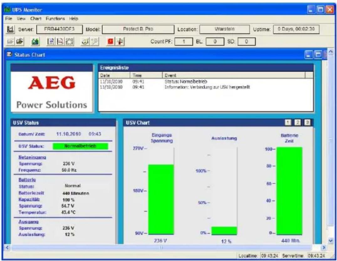
bar
| Metric | Value | | :--- | :--- | | Eingangs Spannung | 236 V | | Auslastung | 12 % | | Battery Zeit | 440 Min. |Sample screen from "CompuWatch"
Details on installation under the various operating systems can be found in the manual on the CD. Updates can be downloaded from www.aegpartnernet.com >> PRODUCTS & SOLUTIONS >> Software >> CompuWatch
8.4 Emergency Power Off
All PROTECT B.PRO series devices feature a connection that allows the immediate disconnection of the UPSoutput for switching off connected devices and does not follow the shutdown process of the controller.

Note:
After activating the emergency switch-off, the outputs of the UPS are de-energised. Only after acknowledgement/resetting of the emergency
switch-off mechanism and manual restart by switching the "UPS On" does the UPS return to normal operating condition.
To install the emergency switch-off mechanism, proceed as follows:
- Check whether the UPS is switched off, and switch it off if necessary (standby operating mode).
- Remove the plug part from the EPO insert on the back of the UPS by loosening the two external screws (see also Page 26, Item 11).
- Connect a floating NC contact (loadability of at least 60 V DC/30 V AC 20 mA) to the pins of the plug part.
- For this purpose, use a flexible cable with a diameter of min. 0.5 mm^2 and max. 2.5 mm^2 . Reconnect the plug and lock the insertion in the socket by tightening the external screws.

The integrated emergency switch-off mechanism is used solely to switch off the UPS power. This is done electronically and does not correspond to an EMERGENCY-STOP device as per DIN EN ISO 13850.
8.5 Overvoltage/data cable protection RJ11 and RJ45 (modem/telephone/fax/network)

Plug the incoming data cable into the "IN" connection on the back of the UPS. Attach the "OUT" connection to your end device using another data cable.

The data cable protection supports networks with a transfer rate of 10 and 100 Mbit/s.
9 Troubleshooting
9.1 Malfunctions
The PROTECT B. PRO outputs detailed fault indications which you or the service personnel can use to quickly and precisely localise and interpret malfunctions which occur. Below you will find suggested processes/solutions for remedying the problem you are experiencing.
If you are not able to solve the problem in this manner, end the entire process, switch off the UPS and disconnect the UPS from the mains. In this case, please contact our hotline (see Page 5).
Have the serial number of the device and the date of purchase handy when doing so. You will be provided with technical support, and a decision on how to proceed further is made based on the description of your problem.
9.1.1 Reference fault code table
(If one of these events occurs, the UPS is switched off)
| Event | Fault | |
| General intermediate circuit malf. | 01 | x |
| Interm. circuit voltage too high | 02 x | |
| Interm. circuit voltage too low | 03 x | |
| Inverter start-up malfunctioning | 11 | x |
| Inverter voltage too high 12 x | ||
| Inverter voltage too low 13 x | ||
| Short-circuit at inverter output | 14 | SHORT |
| Battery voltage too high 27 x | ||
| Battery voltage too low 28 x | ||
| Over-temperature | 41 | EP⚠️ |
| Overload | 43 | OVER LOAD |
| Emergency Power Off activated | x | EP⚠️ |
code

9.1.2 Alarm messages warnings
| Event | Symbol | (flashing) | Alarm |
| Battery undervoltage |  | Periodic warning tone every second | |
| Overload |  | Double periodic warning tone every second | |
| Battery system not connected properly |  | Periodic warning tone every second | |
| Battery system overload | 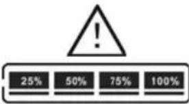 BATTERY CAPACITY BATTERY CAPACITY | Periodic warning tone every second | |
| Battery charging unit malf. |  | Periodic warning tone every second | |
| Battery system fault |  | Periodic warning tone every second | |
9.1.3 Fault indications/solution approaches
If the UPS is not functioning properly or it outputs a fault indication, first try to localise and remedy the problem using the table below.
| Symptom | Possible | Suggested cause solution |
| UPS cannot be switched on, there are no visual or audible fault indications and the mains network appears to be in order. | Mains input not properly connected. | Check the cable connections, especially the seating of the plug in the IEC socket of the UPS. |
| UPS input was (inadvertently) connected to the UPS output. | Check / correct connections as per the description in sections 6.3 & 6.4 on Page 30. | |
Pictograms  are flashing. Warning tone is emitted once a second. are flashing. Warning tone is emitted once a second. | Emergency switch-off active; the plug part or its inserted wire bridge may have been disconnected from the back of the UPS. | Reset the connected switch or insert the plug part. Briefly disconnect the UPS from the mains. |
Pictograms  are flashing. Warning tone is emitted once a second. are flashing. Warning tone is emitted once a second. | The internal or external battery system was not connected correctly. | Check the contact connection of the battery as per Section 6.1/6.2, starting on Page 28. |
| Liquid crystal display - shows fault ind. "14". Warning tone emitted continuously. | UPS switched off automatically due to a short-circuit which has occurred. | Check your connected - electrical loads and your UPS outlet cabling. |
| Liquid crystal display - shows fault ind. "27". Warning tone emitted continuously. | Battery voltage too high or battery charging unit is faulty | Contact your specialist dealer or our hotline. |
| Liquid crystal display - shows fault ind. "28". Warning tone emitted continuously. | Battery voltage too low or battery charging unit is faulty. | Contact your specialist dealer or our hotline. |
| Liquid crystal display - shows fault ind. "41". Pictograms and are flashing. Warning tone is emitted once a second. | UPS switched off automatically due to internally detected over-temperature. | Allow the unit to cool down and then check fan operation. If excessive dust is present, clean the fan. |
| Pictograms and OVER LOAD are flashing. Warning tone is emitted twice a second. | UPS is overloaded. | Reduce the load of the UPS by discon- necting some of your electrical loads. |
| Pictogram OVERLOAD and fault code "43" light up on the display. Warning tone emitted continuously. | UPS has switched off automatically due to an excessively high or long-lasting overload. | Disconnect some of the connected devices. Restart the UPS. |
| Fault codes "1", "2", "3", "11", "12" or "13" light up on the display. Warning tone emitted continuously. | UPS is exhibiting an internal fault. | Contact your specialist dealer or our hotline (Be sure to provide the displayed fault code!). |
| Duration of the emergency power supply shorter than goal | Batteries not fully charged or Batteries are old or cell is defective. | Charge the battery system for at least 6 hours again and check its capacity again. If this does not solve the problem, contact your dealer or our hotline. |
10 Service
The PROTECT B. PRO is comprised of state-of-the-art, low-wearing parts. We recommend, however, that you carry out visual checks (especially of the battery and fan) at regular intervals (at least every 6 months, however) to maintain continual availability and operating reliability.

CAUTION!
Working area protection and the safety regulations must be complied with!
10.1 Charging the battery
The battery is automatically charged via the mains connection, regardless of the operating mode (standby, ECO, AVR).
The full charging time of the battery after a longer discharging period should be at least 6 hours.
10.2 Regular checks
The following service work should be carried out:
| Activity | Interval | Described |
| Visual check 6 months | Section 10.2.1 | |
| Battery/fan check 6 months | Sect. | 10.2.2/10.2.3 |
10.2.1 Visual check
When carrying out the visual check:
- Determine whether mechanical damage or foreign bodies can be identified in the device
- Determine whether conductive dirt or dust deposits are located in the device
- Determine whether dust deposits are hindering the supply and removal of heat.
CAUTION!
The PROTECT B.PRO must be de-energised before the following measure is carried out.
In case of very heavy dust accumulation, the device should be carefully blown out with dry compressed air to enable better heat exchange.
The intervals of the visual checks to be carried out primarily depend on the local set-up conditions of the devices.
10.2.2 Battery check
The progressive aging of the battery system can be determined through regular capacity tests. Carry out comparative measurements of the achievable autonomy time every 6 months, e.g. by simulating a mains failure. The load should always be approximately the same as the power normally required. If the measured autonomy time has decreased dramatically since the previous measurement, please contact our hotline (see Page 5).
10.2.3 Fan check
The fans are to be checked regularly for dust accumulation and any noticeable unusual noises. If the supply air openings are
stopped up, clean them. In case of unusually loud or turbulent running, please contact our hotline (see Page 5).
10.3 Battery replacement
ATTENTION:
A battery can cause an electric shock and can therefore be considerably dangerous if handled improperly.
The following precautionary measures should be implemented before the batteries are replaced.
- Remove any rings, watches or other metallic objects that you may be wearing.
- If the spare battery kit is damaged in any way or shows signs of leakage, contact your specialist dealer immediately.
- Recycle or dispose of the used battery in an appropriate manner. Under no circumstances may the batteries be disposed of in an open fire. The batteries could explode.

Note:
Be aware of the weight of the integrated battery systems. Have another person assist you if necessary.
The battery system is located directly behind the front panel. For easier handling, the battery systems are delivered completely pre-configured.
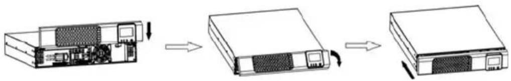
The procedure for replacing the kit can be seen in the following example using a PROTECT B. PRO with an internal battery system:
- Grasp the left and right sides below the front panel and pull the front panel out toward the front. The lock disengages...
- ...and you can swivel the entire front section upward. Do not disconnect the ribbon cable to the liquid crystal display! The mechanical parts must be handled without the use of great force.
- Now disconnect the internal battery system by detaching the two battery connectors from one another.
flowchart
graph LR
    A["Front Panel"] --> B["Internal Storage Unit"]
    B --> C["Internal Component with Display and Control"]
- After loosening the two screws of the battery protection plate, remove the plate from the front. When doing so, guide the battery connector through the intended opening.
- Now remove the entire battery kit by carefully and slowly pulling it out from the front. Be aware of the weight involved, especially with the more powerful models.

Note:
Before inserting the new battery drawer, you must check the battery system for compatibility once again (see also Page 13).
- Now insert the new spare kit in reverse order and finally screw the removed battery protection plate back on.
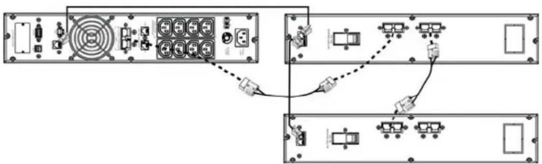
natural_image
Technical line drawings of two electronic device setups with ports and connectors (no text or symbols)- Then reconnect the internal battery system by connecting the two battery connectors to one another.

When making the connection, make sure that you attach the plugs quickly and securely into one another. Any minor electric arcing that may occur when doing so is insignificant.
- Then slowly close the front panel in the reverse order using appropriate caution. Make sure that you don't pinch any cables; always handle the front panel with both hands (applying even force on the left and right).
flowchart
graph LR
    A["Internal Circuit"] --> B["Server"]
    B --> C["Arrow Up"]
    B --> D["Arrow Down"]

Note on the PROTECT B.1800 (BP) PRO:
When replacing external battery systems, we strongly recommend replacing all battery banks for technical reasons.

Disposal of waste batteries (applicable in the European Union and other European countries with separate collection systems)
This symbol on the battery or on the packaging indicates that the battery provided with this product shall not be treated as household waste. On certain batteries this symbol might be used in combination with a chemical symbol. The chemical symbol "Pb" (lead) is added if the battery contains more than 0.4% lead.
By ensuring these batteries are disposed of correctly, you will help prevent potentially negative consequences for the environment and human health which could otherwise be caused by inappropriate waste handling of the battery. The recycling of the materials will help to conserve natural resources.
In case of products that for safety, performance or data integrity reasons require a permanent connection with an incorporated battery, this battery should be replaced by qualified service staff only.
To ensure that the battery will be treated properly, hand over the product at end-of-life to the applicable collection point for the recycling of electrical and electronic equipment.
For more detailed information about recycling of this battery, please contact your local Civic Office, your household waste disposal service or the shop where you purchased the product.
11 Storage, Removal and Disposal
11.1 Storage

Long storage periods without occasional charging or discharging can lead to permanent damage of the battery.
When the battery is stored at room temperature (20 °C to 30 °C), a self-discharge of 3-6% per month takes place due to internal reactions. Storage at temperatures above room temperature should be avoided. A high storage temperature also means increased battery self-discharge.
Batteries stored at room temperature should be recharged every 6 months to preserve their full capacity and service life.

The PROTECT B. PRO should be connected to the mains network before being put into storage to ensure that the battery is fully charged. The charging duration should be at least 6 hours.
11.2 Removal
Removal is carried out by following the installation description in reverse.
11.3 Disposal
Please dispose of the individual parts of the device as prescribed and in compliance with legal guidelines upon the final decommissioning in the interest of environmental protection and recycling. Please keep in mind that violations of these regulations can be seen as a summary offence.

Disposal of old electrical & electronic equipment (applicable in the European Union and other European countries with separate collection systems)
This symbol on the product or on ist packaging indicates that this product shall not be treated as household waste. Instead it shall be handled over the applicable collection point for the recycling of electrical and electronic equipment.
By ensuring this product is disposed of correctly, you will help prevent potential negative consequences for he environment and human health, which could otherwise be caused by inappropriate waste handling of this product. The recycling of materials will help to conserve natural resources.
For more detailed information about recycling of this product, please contact your local Civic Office, your household waste disposal service or the shop where you purchased the product.
12 Appendix
12.1 Glossary (technical terms)
| AVR | Automatic Voltage Regulation against mains voltage deviations |
| Class D See device protection | |
| DC/DC booster Circuitry for increasing a direct voltage to a higher voltage level | |
| Device protection A term from overvoltage technology | |
| The classical mains overvoltage protection is comprised of a lightening current arrester (Class B), overvoltage protection (Class C) and the so-called device protection (Class D) | |
| ECO Measure for system efficiency optimisation | |
| Efficiency Corrective Optimiser | |
| EPO Device for emergency switch-off | |
| Emergency Power Off | |
| LED | Light Emitting DiodeElectronic semiconductor component used for visual signaling. |
| PFC | Power Factor CorrectionCircuitry for minimising feeding back to the mains (especially important in the connection of nonlinear loads) |
| SNMP | Simple Network Management ProtocolFrequently encountered protocol on the network for managing components |
| VFD | Output _oltag and Frequency Dependent from mains supplyThe UPS output depends on the mains voltage and frequency fluctuations. Previous designation: OFFLINE |
| VI | Output _oltag Independent from mains supplyThe UPS output depends on mains frequency fluctuations, but the mains voltage is processed via electronic/passive voltage regulation units.Previous designation: LINE-INTERACTIVE |
| VFI | Output _oltag and Frequency Independent from mains supplyThe UPS output is independent of the mains voltage and frequency fluctuations. Previous designation: ONLINE |
12.2 Index
A
Abbreviation index ...... 36
Alarm messages ...... 44
Autonomy time 12
AVR 37,53
B
Battery expansion ..... 29
Battery mode 37
Battery test 35, 33
C
CE declaration ...... 20
Cold start 19
Communication 40
Connections 25
D
Device overload 12, 36, 45
Dimensions 15
Display 25,34
E
ECO.... 37
Electrical load connection 30
Emergency Power Off .... 41
G
Glossary 53
Guidelines 15
H
Hotline 5
|
(Initial) Commissioning ..... 31
Indicators 34
Installation 23
Interfaces (PC) 40
M
Mains connection ..... 30
Mains mode 37
Malfunctions 43
Measured values .... 33, 35
0
Operating conditions .... 37
Operator panel 33
Overload ...... 12, 36, 45
Overview (Front/Rear) 25
R
Rack / 19" installation ... 23
RS 232 interface ..... 27, 40
s
Safety precautions ..... 16
Scope of delivery ..... 21
Settings 38
Service 46
Set-up location 22
Signalling 36, 43
Standby 37
Storage 51
System description ..... 9
T
Table of contents 6
Technical data ...... 11
Troubleshooting 43
U
USB 27,40
UPS settings 38
W
Website 5
Weights 15
Guarantee Certificate
Type:
Unit number:
Date of purchase: ....
Dealer stamp/signature
Specifications are subject to change without notice
AEG
Power Solutions
Operating Instructions
8000032013 BAL, en
- Notes on these Operating Instructions
- Duty to provide information
- Make sure that you read through these instructions carefully before attempting to install or operate this device!
- Validity
- Warranty and liability
- Handling
- Hotline
- Copyright
- Table of Contents
- Interfaces and Communication 40
- Troubleshooting 43
- Service 46
- Storage, Removal and Disposal 51
- Appendix 53
- General Information
- Brief overview
- Features of the PROTECT B.PRO:
- System description
- Technical data
- Guidelines
- WARNING:
- Safety Regulations
- General safety precautions
- Danger!
- Attention!
- Information!
- Safety precautions for PROTECT B.PRO
- Risk of burns!
- Risk of electric shock!
- Risk of explosion!
- CE certificate
- AEG
- Power Solutions
- Declaration of Conformity
- Unpacking and checking
- Check the contents of the delivery for completeness:
- External battery modules include the following with delivery:
- Set-up location
- Installation
- Installation in a 19" rack
- Set-up as an upright device (tower)
- Overview of Connections, Controls and Display Components
- Front view
- Explanations:
- Rear view (connections)
- Electrical Connection
- Internal battery contact connection (all models except PROTECT B.1800PRO)
- External battery unit contact connection (PROTECT B.1800 PRO only)
- Mains connection
- Electrical load connection
- Operation and Control
- Initial commissioning
- Switching ON the UPS
- Switching OFF the UPS
- Operator panel
- Overview
- Operating buttons (navigation)
- Indicators (LED indicators)
- Liquid crystal display
- Abbreviation index
- Audible signals
- UPS operating states
- UPS settings
- Interfaces and Communication
- Computer interfaces RS232 and USB
- Communication slot
- Shutdown and UPS management software
- Emergency Power Off
- Note:
- Overvoltage/data cable protection RJ11 and RJ45 (modem/telephone/fax/network)
- Troubleshooting
- Malfunctions
- Reference fault code table
- Alarm messages warnings
- Fault indications/solution approaches
- Service
- CAUTION!
- Charging the battery
- Regular checks
- Visual check
- Battery check
- Fan check
- Battery replacement
- ATTENTION:
- Note on the PROTECT B.1800 (BP) PRO:
- Disposal of waste batteries (applicable in the European Union and other European countries with separate collection systems)
- Storage, Removal and Disposal
- Storage
- Removal
- Disposal
- Appendix
- Glossary (technical terms)
- Index
- A
- B
- C
- D
- E
- G
- H
- |
- M
- 0
- R
- s
- T
- U
- W
Brand : AEG
Model : Protect B 2300 PRO
Category : Inverter