
Protect A. 1400 VA - Inverter AEG - Free user manual and instructions
Find the device manual for free Protect A. 1400 VA AEG in PDF.

| Product Type | Uninterruptible Power Supply (UPS) |
| Model | Protect A. 1400 VA |
| Brand | AEG |
| Power Capacity | 1400 VA / 980 W |
| Topology | Line-Interactive |
| Input Voltage | 220-240 V AC |
| Output Voltage | 230 V AC ± 10% |
| Frequency | 50/60 Hz (auto-sensing) |
| Waveform | Simulated sine wave |
| Battery Type | Sealed Lead-Acid (maintenance-free) |
| Number of Outlets | 8 (IEC 320 C13 + 1 C19) |
| USB / Serial Port | USB and RS-232 |
| Dimensions (W x D x H) | 140 x 400 x 300 mm |
| Weight | 15 kg |
| Audible Alarms | On battery, low battery, overload, fault |
| Protection Features | Surge protection, overload protection, short-circuit protection, battery deep discharge protection |
| Operating Temperature | 0°C to 40°C |
| Storage Temperature | -15°C to 45°C |
| Battery Charging Time | 4-6 hours to 90% |
| Typical Backup Time (half load) | 15-20 minutes |
| Certifications | CE, TÜV |
Frequently Asked Questions - Protect A. 1400 VA AEG
User questions about Protect A. 1400 VA AEG
0 question about this device. Answer the ones you know or ask your own.
Ask a new question about this device
Download the instructions for your Inverter in PDF format for free! Find your manual Protect A. 1400 VA - AEG and take your electronic device back in hand. On this page are published all the documents necessary for the use of your device. Protect A. 1400 VA by AEG.
USER MANUAL Protect A. 1400 VA AEG
Thank you for deciding to purchase the PROTECT A. UPS from AEG Power Solutions.
The following safety instructions are an important part of the operating instructions are will protect you against problems from operating errors and possible dangers. Please read these instructions carefully prior to commissioning!
1 Notes on these Operating Instructions
Duty to provide information
These operating instructions will help you to install and operate the U _ninterruptible Power Supply (UPS), PROTECT A. 1000 or PROTECT A. 1400 - referred to as PROTECT A. in this document - safely and properly, and for its intended purpose. These operating instructions contain important information for avoiding dangers.
Please read these instructions carefully prior to commissioning!
These operating instructions are a composite part of PROTECT A.
The owner of this unit is obliged to communicate the full content of these operating instructions to all personnel transporting or starting the PROTECT A. or performing maintenance or any other work on the unit, without the information having to be requested.
Validity
These operating instructions comply with the current technical specifications of PROTECT A. at the time of publication. The contents do not constitute subject matter of the contract, but serve for information purposes only.
Warranty and liability
We reserve the right to alter any specifications given in these operating instructions, especially with regard to technical data and operation, prior to start-up or as a result of service work.
Claims in connection with supplied goods must be submitted within one week of receipt, along with the packing slip. Subsequent claims cannot be considered.
The warranty does not apply for damage caused by non-compliance with these instructions (such damage also includes damage to the warranty seal). AEG will accept no liability for consequential damage. AEG will rescind all
obligations such as warranty agreements, service contracts, etc. entered into by AEG or its representatives without prior notice in the event of maintenance and repair work being carried out with anything other than original AEG parts or spare parts purchased from AEG.
Handling
PROTECT A. is designed and constructed so that all necessary steps for start-up and operation can be performed without any internal manipulation of the unit. Maintenance and repair work may only be performed by trained and qualified personnel.
Illustrations are provided to clarify and facilitate certain steps.
If danger to personnel and the unit cannot be ruled out in the case of certain work, it is highlighted accordingly by pictographs explained in the safety regulations of chapter 3.
Hotline
If you still have questions after having read these operating instructions, please contact your dealer or our hotline:
Tel.: +49 (0) 1805 234 787
Fax: +49 (0) 1805 234 789
Internet: www.AEGpartnerNet.com
Copyright
No part of these operating instructions may be transmitted, reproduced and/or copied by any electronic or mechanical means without the express prior written permission of AEG.
© Copyright AEG 2009. All rights reserved.
Table of Contents
1 Notes on these Operating Instructions....4
2 System Overview ......7
2.1 Brief Overview....7
2.2 Principle of Operation....8
3 Safety 10
3.1 General Safety Instructions....10
3.2 Safety Instructions for PROTECT A....10
3.3 CE Certificate....14
3.4 Technical Data ....15
4 Set-up....17
4.1 Unpacking and Inspection....17
4.2 Installation Site....18
4.3 Connections, Operating and Display Elements .....19
5 Installation and Operation ....20
5.1 Test ....20
5.2 Installation....20
5.3 Charging....21
5.4 Connecting the Load (e.g. computer) ......21
5.5 RJ11 and RJ45 Data Line Protection
(Modem / Phone / Fax / Network)....22
5.6 Communication Connection, Connection with USB or Serial Cable 22
5.7 Operation ......23
5.7.1 Normal Operation ......23
5.7.2 Battery Operation / Autonomous Operation .....24
5.7.3 System Diagnosis / Fault Test....25
5.7.4 Shutdown and UPS Management Software.....25
6 Displays and Troubleshooting....26
6.1 LC Display....26
6.2 Warning Sounds....29
6.3 General Troubleshooting and Fault Rectification.....29
7 Maintenance....31
7.1 Battery Replacement....32
8 Storage and Disposal....34
9 List of Terms....35
9.1 Technical Terminology....35
2 System Overview

PROTECT A. is an uninterruptible power supply (UPS) for essential loads such as PCs, workstations relatively small-scale telecommunication equipment and similar devices.
The PROTECT A. series is a compact, interactively operating UPS available with nominal power output ratings 500, 700, 1000 and 1400 VA.
This document describes both types, PROTECT A. 1000 and PROTECT A.1400.
2.1 Brief Overview
The LED display and a pushbutton switch are located on the front of the UPS for straightforward monitoring and operation. The display unit clearly shows the various operating modes using simple pictograms and displays the voltage values and utilisation level of the UPS in numerical format. In addition, the remaining standby time in battery operation is shown in numerical format.
The connections for the mains and the loads are located on the rear of the PROTECT A., as are the communication interfaces and connections for telephone lines/network cables.
Important UPS data is monitored permanently and transferred to the computer via USB or the RS232 interface and using the CompuWatch software.
Features of the PROTECT A.:
♦ VI (line – interactive) protection technology
◆ Automatic voltage regulation against mains voltage deviations (AVR)
◆ Microprocessor control for high reliability
◆ Modern battery management with integrated protection against exhaust. discharge and overloading
◆ User-friendly LC display with optimum legibility
◆ Intelligent monitoring system with USB and RS232 interfaces
◆ Overvoltage protection (RJ11/RJ45) for fax, modem, phone and network
◆ CompuWatch software for shutdown, status messages and measurement values for all major operating systems (incl. Windows, Mac, Linux)
◆ Compact design
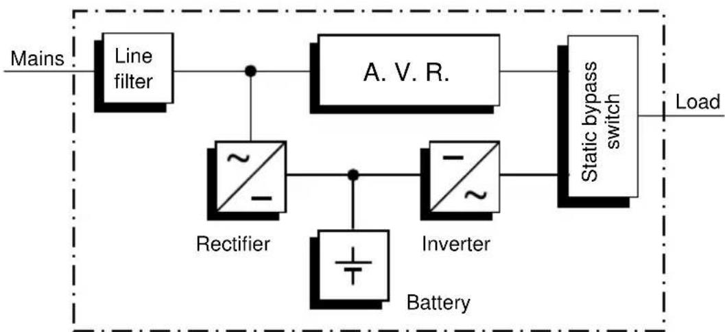
2.2 Principle of Operation
The UPS is connected to a shockproof socket between the public utility's mains and the loads to be protected.
Under normal operating conditions, i.e. if PROTECT A. is supplied with mains voltage, the battery charger will ensure that the batteries are always completely charged.
During this operating status, the loads connected to PROTECT A. are supplied with voltage via mains filters which provide effective protection against mains voltage peaks and high-frequency faults.
In case of sustained mains undervoltage or overvoltage within defined ranges, the automatic voltage regulator (AVR) further stabilises the load voltage. As a result, voltage fluctuations in the public utility's mains are reduced to a level which is acceptable for the loads. This is performed without recourse to
the internal energy storage, something which in turn has a positive effect on battery availability.
flowchart
graph LR
    A["Mains"] --> B["Line filter"]
    B --> C["Rectifier"]
    C --> D["A. V. R."]
    D --> E["Static bypass switch"]
    E --> F["Load"]
    C --> G["Battery"]
    G --> H["Inverter"]
    H --> E
UPS Block diagram PROTECT A.
The static bypass switch is activated in the event of a mains failure. The inverter then takes over the voltage supply of the connected loads, in order to prevent the risk of data loss or damage to the loads. PROTECT A. supplies voltage until the batteries are discharged or your IT system has been shut down and switched off properly.
The standby time mainly depends on the connected loads. If the mains power supply is back to normal values, the UPS will switch back the loads to mains supply. The battery charger will then recharge the batteries.
For safety reasons (as required by German standards, VDE), the mains input in the unit will be disconnected by a two-pole switch in the event of a mains failure. Energy backfeed to the mains and voltage supply to the pins of the mains connector are thus reliably avoided.
Furthermore, additional measures ensure effective protection for the data/network interface.
3 Safety
3.1 General Safety Instructions
Read these operating instructions carefully prior to commissioning of the PROTECT A. UPS and observe the safety instructions!
Only use the unit if it is in a technically perfect condition and always in accordance with its intended purpose, while being aware of safety and danger aspects, and in accordance with the operating instructions! Immediately eliminate any faults that could be detrimental to safety.
The following pictograms are used in these operating instructions to identify dangers and important information:
Danger!
Identifies risk of fatal injury to the operator.

Attention!
Identifies risk of injury and risk of damage to the device and parts of the device.

Information!
Useful and important information for operating the UPS.
3.2 Safety Instructions for PROTECT A.
This chapter contains important instructions for the PROTECT A. UPS. These must be followed during assembly, operation and maintenance of the uninterruptible power supply and the batteries.
The UPS is live, and the voltage can be dangerous. The unit may only be opened by trained and qualified personnel. Repairs may only be carried out by qualified customer service staff!
The output may be live, even if the UPS is not connected to the mains supply, as the UPS has its own internal power supply (battery)!

For health and safety reasons, the unit must be earthed correctly!
PROTECT A. may only be operated with or connected to a 220 / 230 / 240 VAC mains with protective grounding using a mains connection cable with PE conductor (included in the delivery) that has been tested in accordance with German standards (VDE).
Risk of burning!

The battery has powerful short- circuit currents. Incorrect connection or isolation faults can lead to melting of the plug connections, sparking potential and severe burns!

The unit has a warning signal that sounds when the battery voltage of PROTECT A. is exhausted or when the UPS is not working in its normal mode.

Observe the following safety instructions to ensure permanent operational safety of and safe work with the UPS:
♦ Do not dismantle the UPS!
◆ (The UPS does not contain any parts that require regular maintenance. Bear in mind that the warranty will be invalidated if the unit is opened!)
- Do not install the unit in direct sunshine or in close proximity of heaters!
◆ The unit is designed to be installed inside in heated rooms. Never install the UPS in the vicinity of water or in an excessively damp environment!
◆ Condensation may occur if the UPS is brought from a cold environment into the room where it is to be installed. The UPS must be absolutely dry prior to start-up. As a result, leave it to acclimatise for at least two hours.
♦ Never connect the mains input and the UPS output!
◆ Ensure that no fluids or foreign bodies can penetrate the UPS!
Do not block the air vents of the unit! Make sure, for example, that children do not insert any objects in the ventilation openings!
♦ Do not connect household appliances such as hairdryers to the UPS!
◆ The mains connection should be near the unit and easily accessible to facilitate disconnecting the AC input or pulling out the plug!
During operation, do not disconnect the mains connection cable from the UPS or from the socket outlet in the building (shockproof socket), otherwise the protective grounding of the UPS and all the loads connected to it will be cancelled.
Danger! Electric shocks!
Even after the mains voltage has been disconnected, the components within the UPS remain connected to the battery and can thus cause electric shocks. It is therefore imperative to disconnect the battery circuit before carrying out any maintenance or repair work!
If it is necessary to replace the battery or carry out maintenance work, this must be done by or under the supervision of a specialist familiar with batteries and the necessary safety precautions!
Only authorised persons are allowed in the vicinity of the batteries!
When replacing the batteries, the following must be observed: Only ever use identical, maintenance-free sealed lead batteries with the same data as the original batteries.

Danger! Explosive!
Never throw batteries into open fire. Never open or damage batteries. (Electrolyte may leak out and damage skin and eyes. It may be toxic!)

Batteries can cause electric shocks and high short-circuit currents.
Therefore, take the following safety precautions when working with batteries:
◆ Take off watches, rings and other metallic objects!
♦ Only use tools with insulated handles!

For personal safety reasons, never switch on the main switch when the mains connector of PROTECT A. is disconnected!
3.3 CE Certificate
AEG
Power Solutions
Declaration of Conformity
Document - No. CE 0107
We
declare under our sole responsibility that the product
Uninterruptible Power Supply (UPS)
Protect A.
type power 1000VA / 1400VA
to which this declaration relates is in conformity with the following standards or other normative documents
EN 62040-1-1:2003
EN 62040-2:2006 Class C2
EN 61000-3-2:2006
EN 61000-3-3:2005
Following the provisions of directives
2004/108/EEC EMC-Directive
2006/95/EEC Low Voltage Directive
Year of labelling the CE - Mark: 2008
Germany, 59581 Warstein, 2008-11-03
Voltage range without battery 170 Vac to 280 Vac
Frequency (automatic detection) 50 / 60 Hz
Connection Non-heating appliance
connector IEC 320 C 14
UPS output
Rated output voltage / 230 Vac
AVR technology
Rated output voltage in ±10%
battery operation
Frequency in battery operation 50 Hz / 60 Hz ±1Hz
Nominal output current 4.3 A (PROTECT A. 1000)
6.1 A (PROTECT A. 1400)
Changeover time
in the event of a mains failure 2-6 ms (typical)
Type of voltage approximated sine
Connection 6 non-heating appliance
connectors IEC 320 C 13
with overvoltage protection,
4 with UPS back-up
Protection against over- yes
temperature and short circuit
Battery
Autonomy time at nominal load
Exhaustive discharge protection/
protection against excess load
3 min
yes
Charging time
(to 90 % of rated capacity) 6 h
Type Sealed, maintenance-free
PROTECT A.1000 2 block batteries 12 V / 7 Ah
e.g. CSB, type GP1272F2 3-5 years acc. to EUROBAT Yuasa, type NP7-12D Connection plug 6.3 mm Panasonic, type LC-R127R2P (Faston 250)
PROTECT A.1400 2 block batteries 12 V / 9 Ah
e.g. CSB, type HR1234WF2 3-5 years acc. to EUROBAT Yuasa, type NPW7-12D Connection plug 6.3 mm Panasonic, type UP-RW1245P1 (Faston 250)
Communication
Interfaces USB and RS232
Shutdown software on CD For all common operating
systems, e.g. Windows, Linux, Mac, Unix, FreeBSD, Novell, Sun
General data
| Inherent noise (1 m distance) < 45 dB(A) | |
| Operating temperature range 0 °C - 40 °C | |
| Humidity | 0 to 90 % (without condensation) |
| Installation height | Up to 1000 m at nominal output |
| Housing colour | Silver/black |
| Dimensions W x H x D [mm] | 145 x 205 x 405 |
| Weight [kg] | 9.5 kg (PROTECT A. 1000) 10 kg (PROTECT A. 1400) |
| Cooling type | Increased natural air cooling |
| Storage temperature range | -15°C to +50°C (UPS electronics) |
| UPS with integrated battery | 0 °C to +40 °C |
| Conformity | CE |
Directives
The PROTECT A. meets the product standard EN 50091.
The CE mark on the unit confirms compliance with the EC outline directives for 73/23 EEC – Low voltage and for 89/336 EEC – Electromagnetic compatibility if the installation instructions described in the operating instructions are observed.
For 73/23 EEC low-voltage directive
Reference number EN 62040-1-1 : 2003
For 89/336 EMC directive
Reference number EN 50091-2 : 1995
EN 61000-3-2 : 1995
EN 61000-3-3 : 1995
4 Set-up
4.1 Unpacking and Inspection
The unit has been completely checked and inspected.
Although the device has been packed and shipped with the usual degree of care, damage during transport cannot be ruled out completely.

Claims for damage during transport must always be made with the transport company!
Check the shipping container for damage on arrival. If necessary, ask the transport company to check the goods and make a record of the damage in the presence of the transport company employee and report the damage to the AEG representative or dealer within eight days of delivery.
Check the content is complete:
♦ PROTECT A. with 1000 or 1400 VA
◆ Mains connection cable with shockproof plug acc. to CEE 7/7
Second mains connection cable with UK plug acc. to BS 1363
◆ Two device connecting cables
◆ USB / RS232 communication cable
◆ Management software “CompuWatch” on CD
♦ Operating instructions
Please contact our hotline (see page 5) in case of any discrepancy.
The original packaging provides effective protection against mechanical shocks and should be retained so the unit can be transported safely later on.
Please keep the plastic packaging bags away from babies and children in order to safeguard against suffocation accidents.
4.2 Installation Site
PROTECT A. is designed to be installed in a protected environment. When installing the unit, pay attention to such factors as sufficient ventilation and suitable ambient conditions.

PROTECT A. is air-cooled. Do not obstruct the air vents!
The UPS should preferably be operated at room temperature (between 15^ C and 25^ C).
Install the UPS in a room that is dry, relatively dust-free and free of chemical vapours.
Make sure that no magnetic storage media are stored and/or operated close to PROTECT A.

Check the nameplate to make sure the voltage and frequency data correspond to the values applicable to your loads.
4.3 Connections, Operating and Display Elements
Front
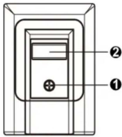
1 Main switch of the UPS (mains switch)
2 LC display with:
- Display of operating mode with pictograms
- Measured value displays [V]
- UPS capacity utilisation display [%]
- UPS remaining op. time display [min.]
- Fault indication
Rear
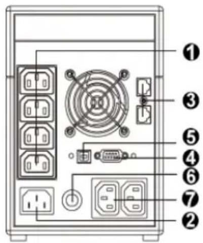
1 Load connections with overvoltage protection and UPS backup
2 Mains connection (UPS input)
3 Data interface for modem/ fax/ phone/ network (RJ11& RJ45)
4 RS232 communication interface (SUB-D 9-pin socket)
5 USB connection
6 Input miniature circuit breaker (can be reactivated after tripping)
7 Load connections with direct mains supply (with overvoltage protection) – without UPS back-up!
5 Installation and Operation
5.1 Check
Remove the UPS from its transport packaging and check that it has not been damaged in transit. If you find any damage, pack the unit up again and send it back to where you purchased it.
natural_image
Line drawing of a server unit with ventilation slots and a close-up view of its front-mounted device (no text or symbols)5.2 Installation
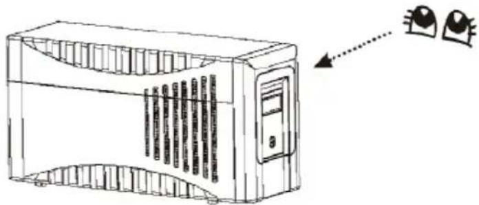
Install the UPS unit in a protected location where there is an adequate air supply and where it will be largely free from dust build-up, corrosive vapours and electrically conductive contamination.

Do not operate your UPS where it is exposed to high ambient temperatures or atmospheric humidity. Set up the UPS at least 20 cm away from the monitor in order to avoid interference.
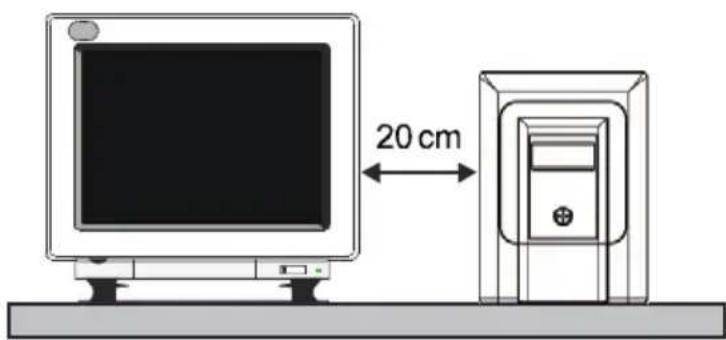
5.3 Charging
The PROTECT A. is supplied with its battery fully charged. Nevertheless, energy may have been lost during transport, so the battery should be fully recharged before it is used for the first time.
Connect the input of the UPS (no. 2 in the figure in chapter 4.3 on page 19) to the mains connection cable provided and plug the mains connector into a suitable shockproof socket. Allow the UPS to charge up for about 6 hours without any load (i.e. without any devices such as computers, monitors, etc. connected to it).

The battery is charged irrespective of the setting of the main switch on the front of the UPS.
5.4 Connecting the Load (e.g. computer)
Connect your loads to the individual UPS backed-up output sockets on the rear of the UPS (chapter 4.3 / no. 1 / pg.19).
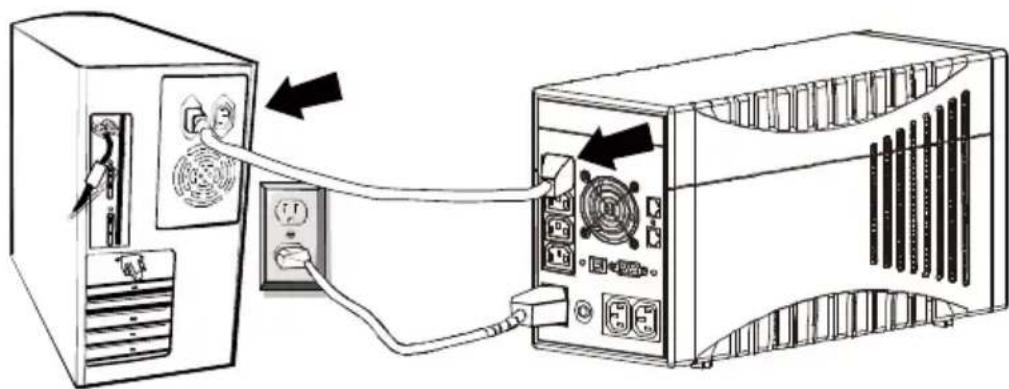
natural_image
Diagram showing two computer setups connected via cable, one with a fan and arrow indicating connection (no text or symbols present)
In this connection, note the special property of the two additional output sockets identified with "SURGE ONLY" (chapter 4.3 / no. 7 / pg. 19).
These are always live irrespective of the other outputs. They are not backed up by the UPS, nor can they be switched off using the main switch of the UPS. It is intended for loads that should be protected against overvoltage but do not necessarily need a continued power supply (emergency power) in case of a mains failure. Limit the power to max. 1000 W.
5.5 RJ11 and RJ45 Data Line Protection (Modem/ Phone/ Fax/ Network)
Connect the incoming phone line/network cable into the "IN" connection on the back of the PROTECT A.
|
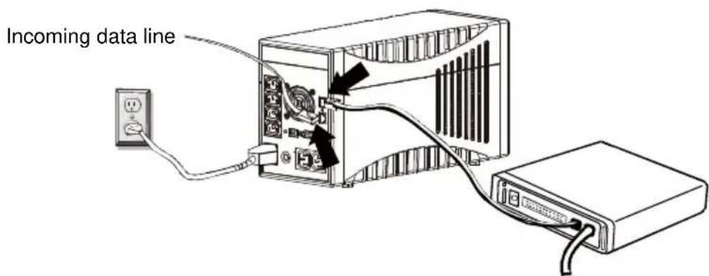
Connect the data terminal unit (phone, fax, modem) to the "OUT" socket.

The data line protection supports networks with transmission rates between 10 and 100 Mbit/s.
Data lines are not supplied with the UPS.
5.6 Communication Connection, Connection with USB or Serial Cable
In order to allow unsupervised shutdown of the operating system, connect the RS232 or USB cable as shown in the drawing.
The USB connection is automatically detected.
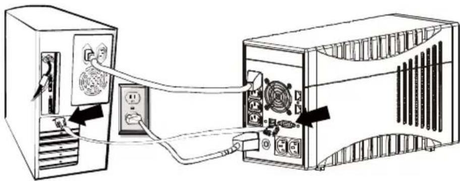
natural_image
Diagram showing connection between two computer units via cable, no text or symbols present
The interfaces are mutually exclusive. There is no provision for simultaneous operation of RS232 and USB.
5.7 Operation
Once you have connected the UPS to a suitable mains connection, you can start operation using the UPS main switch.
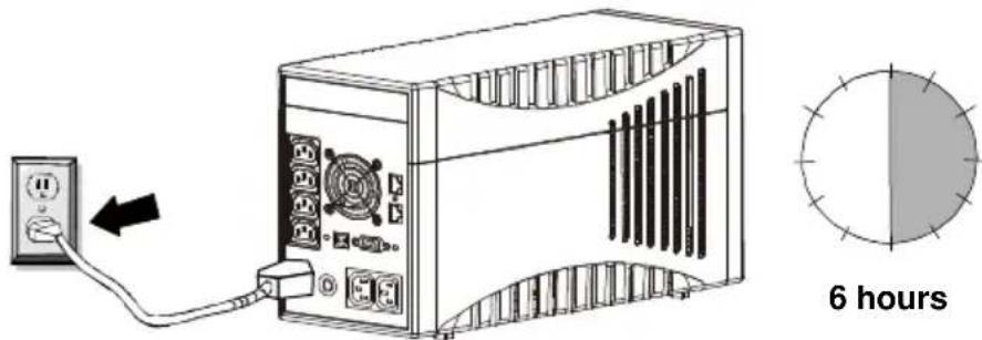
Switching ON and OFF:
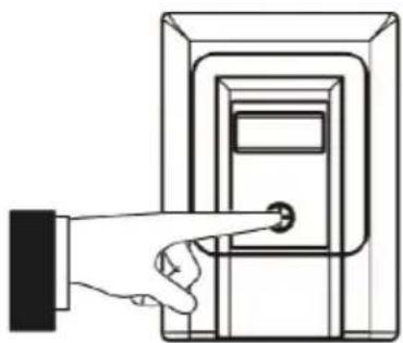
natural_image
Line drawing of a hand pressing a button on a rectangular device (no text or symbols)To switch on, press the main switch on the front of the UPS (chapter 4.3 / no. 1 / pg.19). You must be able to feel this engage in its 2nd position.
➢ Press the main switch again to switch off the UPS.
Normally, the UPS operates continuously. The UPS now supplies the output with voltage, this being signalled by activation of the blue backlighting on the LC display (chapter 4.3 / no. 2 / pg. 19).
5.7.1 Normal Operation
During normal operation, i.e. when mains voltage is available, the built-in battery charger keeps the batteries fully charged and the mains voltage monitoring system switches the inverter to standby mode.
The connected loads are powered using the monitored and filtered mains voltage, which is additionally stabilised by the integrated A.V.R. control unit. The “LINE MODE” symbol shows that the unit is active.
5.7.2 Battery Operation / Autonomous Operation
When there is a mains failure or if the input voltage moves outside the tolerance range, the inverter automatically switches over to autonomous mode and supplies the loads with voltage from the batteries. This drains the capacity of the batteries and they are discharged. This status is signalled by the battery symbol flashing as well as an intermittent acoustic signal (chapter 4.3 / no. 2 / pg. 19).
If the UPS does not automatically return to normal operation after a few minutes, close all your work as usual and switch off the loads (e.g. PC) before the batteries are fully discharged. This lengthens the service life of the batteries! Switch OFF the UPS by pressing the main switch.
During the discharge process as the battery capacity consistently drops, the battery symbol flashes, accompanied by an intermittent acoustic signal (once every 10 seconds). The electronics of the UPS switch off the voltage supply of the loads shortly after the battery undervoltage limit is reached (the battery logo above the battery voltage display also flashes; acoustic signal sounds every second).
Never store the unit in this condition! The discharged battery system should be recharged within a week at the latest.
When the mains voltage comes back, the UPS must be switched on again using the main switch (only applies if it was previously switched off manually), in order to recharge the battery and thus store sufficient battery capacity for any possible future mains failures.
The batteries are automatically charged when the mains is present. The battery charging time (to 90% of rated capacity) is about 6 hours after being previously fully discharged.
5.7.3 System Diagnosis / Fault Test
If the monitoring electronics detect an irregularity, the fault indicator is activated which is signalled by the “Fault” pictogram and a digital fault code, possibly accompanied by an acoustic fault signal. This might occur because the battery undervoltage limit has been reached, if the temperature has risen too high, or it might indicate that the internal battery system needs to be renewed.

Faults detected and signalled during diagnosis must be rectified, otherwise there is a risk of load voltage loss if a mains failure occurs!
5.7.4 Shutdown and UPS Management Software
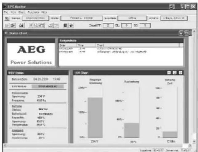
The “CompuWatch” software specially developed for these purposes by AEG continuously checks the mains supply and the UPS status.
bar
EAG Power Solutions | Period | Sales (V) | Profitability (%) | Return on Equity (%) | |---|---|---|---| | 2015 | 234 V | -100% | 100 | | 2016 | 234 V | -80% | 90 | | 2017 | 234 V | -60% | 40 | | Total Return on Equity (2015-2017) | 234 V | -30% | 20% | Source: EAG Data; Summary: QTD;In conjunction with the “intelligent” UPS, this guarantees the availability of the EDP components as well as the data security. The “CompuWatch” shutdown software supports different operating systems, e.g. Windows Linux, Unix, Mac OS X, etc.
Refer to the manual on the CD for details about installing the software on the various operating systems. Other tips and information as well as updates are available from our website at http://www.AEGpartnerNet.com >> PRODUCTS >> Software >> CompuWatch.
6 Displays and Troubleshooting
6.1 LC Display
The blue backlit display is automatically activated after the mains voltage is connected. It operates irrespective of the main switch setting and also when a fault is indicated.
1) The start of operational readiness is signalled on the LC display by all the information content lighting up for about 3 seconds.
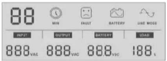
2) Mains/normal operation (see also chapter 5.7.1, page 23) is shown by the "LINE MODE" pictogram.
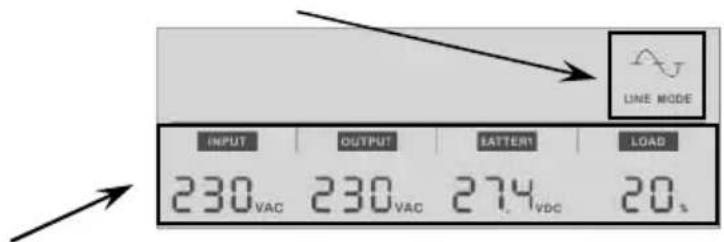
The bottom half of the display shows in the INPUT and OUTPUT voltages of the UPS, the battery (charging) voltage (BATTERY) and the percentage capacity utilisation (LOAD) of the UPS.
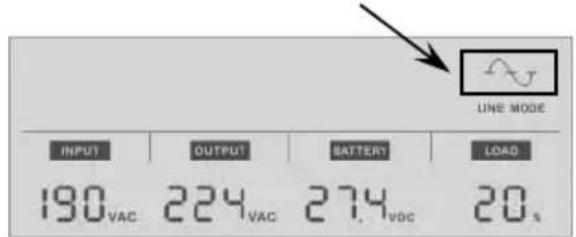
3) If the UPS is in voltage-regulating operating mode, the sine part of the "LINE MODE" pictogram flashes every second.
4) If the UPS is in battery mode, the "BATTERY" pictogram lights up and the battery symbol flashes every second.
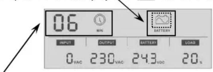
The remaining standby time is displayed during battery operation according to the load applied. This time is shown in minutes and is indicated by the "MIN" pictogram.

The display shows "0" if the voltage values detected for the input or output are below 40 VAC.
5) The following sample display shows battery charging with the master switch switched off.
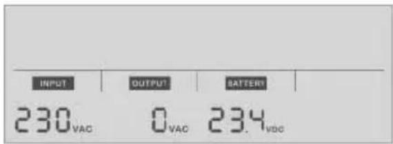

The value "0" is automatically displayed for "OUTPUT" if the UPS is in this switched-off condition.
ATTENTION: This does not been the unit has been de-energised in accordance with VDE definitions!
6) Fault indication by the "FAULT" pictogram, associated with a digital fault code in accordance with the table below:
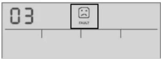
Fault indications with the "FAULT" pictogram lit up.
| Fault CODE | Possible fault cause |
| 01 | Output short circuit(output voltage less than 60 V) |
| 02 | Overload indicatorImmediate fault message in mains/normal operation with a capacity utilisation of > 120%, at a capacity utilisation > 110% the fault message comes after 5 minutes or after 30 seconds in battery operation. |
| 03 | Output voltage deviation, outside the permitted tolerance range |
| 04 | Fan fault |
| 05 | Overload of booster stageAcoustic alarm after 10 minutes with activated booster stage and > 86% load; shut-down after a further 5 minutes. |
6.2 Warning Sounds
| Warning sound | Meaning |
| Sounds every 10 seconds. | UPS is operating in battery mode. |
| Sounds every second. | UPS is running in battery mode and will shortly shut down (battery system has reached the battery undervoltage limit). |
| Sounds every two seconds | Battery system faulty, it may have to be renewed (battery diagnosis negative). |
| Sounds twice every second | UPS output is overloaded. |
| Sustained warning sound | UPS faulty(see also fault indication (fault CODE table)) |
6.3 General Troubleshooting and Fault Rectification
| Fault Cause Solution | ||
| No LED display on the front cover plate | Battery missing Insert the battery and first charge it up for at least 8 hours | |
| Battery fault Renew the battery with a battery of the same type | ||
| On/off switch not pressed Press the switch again | ||
| Alarm buzzer sounds continuously with normal AC supply | UPS overload Check whether the load matches the UPS capacity indicated in the technical data | |
| Data backup time is only very short on power failure | UPS overload Remove loads that are less important | |
| Battery voltage is too low | Charge the battery for at least 6 hours | |
| Battery fault die to high temperature in the operating environment or incorrect treatment of the battery; advanced battery ageing | Renew the battery with a battery of the same type | |
| Mains normal, but “Battery” LED flashes | Miniature circuit breaker triggered | Press reset button of miniature circuit breaker; |
| Mains cable loose Insert the plug firmly into the non-heating appliance socket of the UPS. | ||
| Communication between UPS and computer interrupted | Software is not installed correctly | Check the software settings.Support is available at www.AEGpartnerNet.de |
| Cable not connected properly | Check that the RS232/USB cable is firmly connected to the COM or USB port of the computer and confirm the settings again | |
If you cannot solve the problem that has occurred, stop the entire procedure, switch off the UPS and disconnect the connector from the socket. Please contact our hotline in this case (see page 5).
Please have the serial number of the unit as well as the purchase date at hand. The hotline will provide you with technical support and can inform you about further procedures once you have described the problem.
7 Maintenance
The PROTECT A. consists of state-of-the-art, non-wearing components. We do, however, recommend regular visual checks of the unit to maintain its continuous availability and operational reliability. Check whether:
◆ there is any mechanical damage or foreign bodies can be found in the system,
◆ any conductive dirt or dust has accumulated in the unit,
◆ accumulation of dust affects heat supply and dissipation.
CAUTION:
The PROTECT A. must be disconnected from the power supply prior to carrying out the following work.
If large quantities of dust have accumulated, the unit should, as a precaution, be cleaned with dry compressed air, in order to ensure adequate heat dissipation.
The intervals at which visual checks should be performed are primarily determined by the site conditions.
Checking the battery
Progressive ageing of the battery system can be detected by regular capacity checks. Every 12 months, perform measurements to compare the achievable standby times, e.g. by simulating a mains failure. In this case, the load should always have approximately the same capacity demand. Have the battery system renewed if the time drops drastically compared to the previous measurement.
7.1 Battery Replacement
ATTENTION:
A battery can cause an electric shock, and represents a considerable hazard if handled incorrectly.
The following precautions should be taken before the battery is renewed.
◆ Switch off the UPS and disconnect the mains cable from the socket.
◆ Remove any rings, wristwatch and other metallic objects you may be wearing.
◆ If the replacement battery kit is damaged in any way or shows any signs of leaking, please contact your dealer immediately.
◆ Recycle or dispose of the used battery appropriately. Never dispose of batteries by burning. The batteries might explode.

Note:
If you are not qualified to renew the batteries, do not try to open the battery cover. Leave this work to qualified personnel.
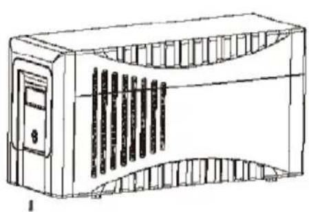
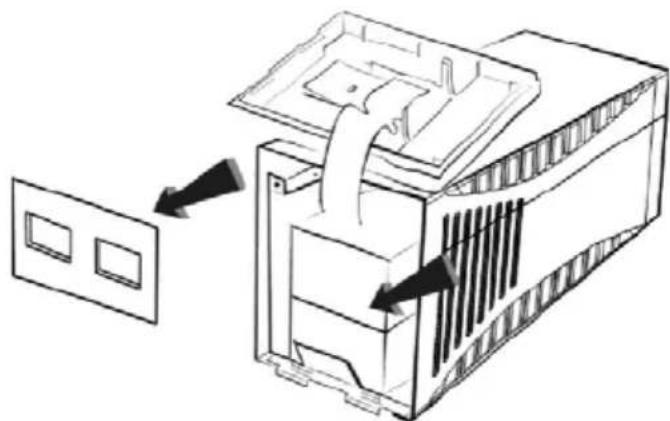
The following 3 pictures show the basic steps for changing the battery system. First remove the screw on the underside of the front panel and pull the front panel forwards away from the unit.
natural_image
Line drawing of a server rack unit with ventilation slots and control panel (no text or symbols)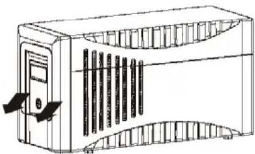
natural_image
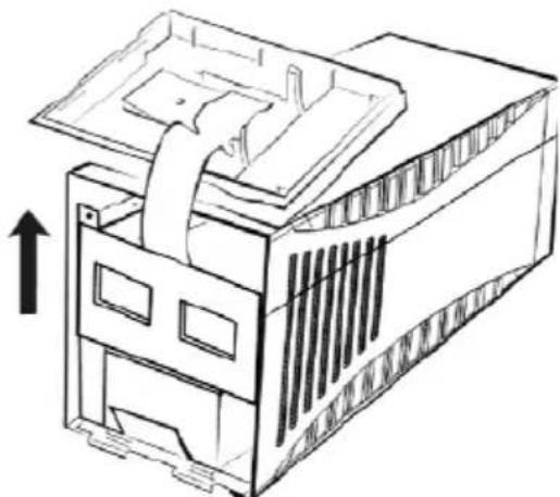
Line drawing of a server rack unit with cooling fins and ventilation slots (no text or symbols)Once you have lifted off the actual front panel (which you can put down on top of the unit as shown – never disconnect the flat-ribbon cable) next remove the internal battery cover.
natural_image
Isometric line drawing of a multi-story building with ventilation grilles and an upward arrow indicating direction (no text or symbols)Now slowly pull the two battery blocks out forwards until you can access the cable plug connections. First disconnect the negative terminal then the positive terminal (avoid allowing these connectors to touch one another or the housing) and then remove the battery system from the housing.
Only install batteries of the same type when renewing the battery system!
natural_image
Technical line drawing of a server rack with two square windows, showing internal structure and directional arrows (no text or symbols)Installation is the same procedure in reverse. Check the polarity is correct when connecting! (First connect the positive terminal, then the negative terminal – plug in the contacts quickly and firmly!). Dispose of the old battery system in an environmentally friendly manner!
8 Storage and Disposal
Storage

Long storage times without charging or discharging the battery at regular intervals may lead to permanent damage of the battery.
If the battery is stored at room temperature ( 20^ C to 30^ C) it will automatically discharge at a rate of 3-6% per month due to internal reactions. Storing the battery at temperatures above room temperature should be avoided. A high storage temperature also means a higher rate of battery degradation.
Batteries that are stored at room temperature should be recharged every six months to maintain their full capacity and service life.

Connect PROTECT A. to the mains before putting it into storage, in order to make sure that the battery is fully charged.
The charging time should be at least 6 hours.
Disposal
In the interest of environmental protection and recycling, please dispose of the individual system components in accordance with the regulations and legal guidelines when permanently taking the system out of operation.
9 List of Terms
9.1 Technical Terminology
| AVR Automatic Voltage Regulation | |
| Automatic voltage regulation against mains voltage deviations | |
| DC/DC booster Circuit technology for increasing a DC voltage to a higher voltage level | |
| EPO E | mergency Power OffDevice for emergency shutdown |
| PFC P | lower Factor CorrectionCircuit technology for minimising system disturbances (particularly important when connecting non-linear loads) |
| Appliance protection Term from overvoltage technologyClassic mains overvoltage protection consists of a lightning surge arrester (Class B), overvoltage protection (Class C) and, finally, what is referred to as appliance protection (Class D) - see alsohttp://www.phoenixcontact.de ("TRABTECH" topic) for example | |
| Class D See appliance protection | |
| LED L | ight Emitting DiodeElectronic semi-conductor component, commonly referred to as an LED, used for optic signalling. |
| SNMP S | imple Network Management ProtocolA protocol encountered frequently in networks for managing / handling components |
| VFD Output Voltage and Frequency Dependent from mains supplyThe UPS output is dependent on mains voltage and frequency fluctuations. Earlier designation: OFFLINE | |
| VI Output V | oltage Independent from mains supplyThe UPS output is dependent on mains frequency fluctuations, but the mains voltage is prepared by electronic / passive voltage control units. Earlier designation: LINE-INTERACTIVE |
| VFI Output V | oltage and Frequency Independent from mains supplyThe UPS output is independent from mains voltage and frequency fluctuations. Earlier designation: ONLINE |
Guarantee Certificate
Type: ....
Unit
number:
Date of
purchase:
Dealer stamp / signature
Errors and changes excepted.
AEG
Power Solutions
Operating instructions
BAL 8000024071 EN
- Notes on these Operating Instructions
- Duty to provide information
- Please read these instructions carefully prior to commissioning!
- Validity
- Warranty and liability
- Handling
- Hotline
- Copyright
- Table of Contents
- System Overview
- Brief Overview
- Features of the PROTECT A.:
- Principle of Operation
- Safety
- General Safety Instructions
- Danger!
- Attention!
- Information!
- Safety Instructions for PROTECT A.
- Risk of burning!
- Danger! Electric shocks!
- Danger! Explosive!
- CE Certificate
- AEG
- Declaration of Conformity
- UPS output
- Battery
- Communication
- Directives
- Set-up
- Unpacking and Inspection
- Check the content is complete:
- Installation Site
- Connections, Operating and Display Elements
- Installation and Operation
- Check
- Installation
- Charging
- Connecting the Load (e.g. computer)
- RJ11 and RJ45 Data Line Protection (Modem/ Phone/ Fax/ Network)
- Communication Connection, Connection with USB or Serial Cable
- Operation
- Switching ON and OFF:
- Normal Operation
- Battery Operation / Autonomous Operation
- System Diagnosis / Fault Test
- Shutdown and UPS Management Software
- Displays and Troubleshooting
- LC Display
- Warning Sounds
- General Troubleshooting and Fault Rectification
- Maintenance
- CAUTION:
- Checking the battery
- Battery Replacement
- ATTENTION:
- Note:
- Storage and Disposal
- Storage
- Disposal
- List of Terms
- Technical Terminology
- Guarantee Certificate
- Power Solutions
Brand : AEG
Model : Protect A. 1400 VA
Category : Inverter