EVID 3.2 - Pregnant BOSCH - Free user manual and instructions
Find the device manual for free EVID 3.2 BOSCH in PDF.

| Product Type | Passive Loudspeaker |
| Model | EVID 3.2 |
| Brand | Bosch |
| Driver Configuration | Two-way (3.5" woofer, 0.75" tweeter) |
| Frequency Response | 80 Hz – 20 kHz |
| Sensitivity (1W/1m) | 86 dB SPL |
| Impedance | 8 ohms |
| Power Handling (RMS) | 30 W |
| Dimensions (H x W x D) | 180 x 120 x 120 mm |
| Weight | 1.5 kg (3.3 lbs) |
| Mounting | Wall-mount bracket included, optional ceiling mount |
| Color | Black or white |
| Input Connection | Spring-loaded terminals (accepts up to 14 AWG) |
| Enclosure Material | ABS plastic with metal grille |
| Weather Rating | IP34 (splash resistant) |
| Application | Indoor/outdoor background music and paging |
| Safety Standards | EN 62368-1, CE, UL 2043 for plenum use |
| Spare Parts / Repairability | Driver and grille replaceable; service manual available |
| Included Accessories | Mounting bracket, screws, user manual |
Frequently Asked Questions - EVID 3.2 BOSCH
User questions about EVID 3.2 BOSCH
0 question about this device. Answer the ones you know or ask your own.
Ask a new question about this device
Download the instructions for your Pregnant in PDF format for free! Find your manual EVID 3.2 - BOSCH and take your electronic device back in hand. On this page are published all the documents necessary for the use of your device. EVID 3.2 by BOSCH.
USER MANUAL EVID 3.2 BOSCH
EV Innovative Design
Table of Contents...... TOC
Safety First TOC
Product Description ....1
Welcome....1
Important Features ....1
Model Summary ......2
Packing List 2
EVID™ Product Family ....3
Product Feature Identification ....3
SAM™ (Strong-Arm-Mount™) System .4
Step-by-Step Installation and Wiring ....4
Step 1 - Mount the SAM™ Bracket ..4
Step 2 - Select Wattage Tap (Models 4.2t and 6.2t Only)....5
Step 3 - Mount the Speaker to the SAM ^TM Bracket .... 5
Step 4 - Wire the Speaker ......6
Step 5 - Secure the Seismic Tab Connection Point ....6
Step 6 - Test System Operation .....6
Packing List (12.1 Subwoofer) .....7
Product Feature Identification (12.1 Subwoofer) 7
Step-by-Step Installation and Wiring (12.1 Subwoofer) 8
Step 1 - Mount the Bracket .....8
Step 2 - Install the Safety Line .....8
Step 3 - Wire the Speaker .....8
Safety First
Table of Contents
Step 4 - Mount the Speaker to the Bracket .... 9
Step 5 - Test System Operation .....10
Safety Agency Compliance ....10
Maintenance ....10
Uniform Limited Warranty ...... 11
Exclusions and Limitations .... 11
Obtaining Warranty Service ...... 11
Incidental and Consequential Damages Excluded 11
Other Rights 11
Speakers and Electronics 11
Appendix A - Integrating the 12.1 Subwoofer ....12
Installation Examples ......12
Using the 12.1 in Passive Mode .....12
Crossover Freq. and Impedance .....12
Using a Separate Amplifier Channel for the 12.1....12
Characteristics of All Subwoofers .....12
Appendix B - Painting the Speaker ....13
Painting Process (3.2, 4.2, 6.2) .....13
Painting the Grille 13
Painting Process (12.1 Subwoofer) ...13
Appendix C - Troubleshooting Table .14
Appendix D - Technical Specs .....15
3.2/3.2t; 4.2/4.2t 15
6.2/6.2t; 12.1 .....16
Notes ......17
Suspending any object is potentially dangerous and should only be attempted by individuals who have a thorough knowledge of the techniques and regulations of rigging objects overhead. Electro-Voice® strongly recommends that all speakers be suspended taking into account all current national, federal, state and local regulations. It is the responsibility of the installer to ensure that all speakers are safely installed in accordance with all such regulations. When speakers are suspended, Electro-Voice® strongly recommends that the system be inspected at least once a year. If any sign of weakness or damage is detected, remedial action should be taken immediately. The user is responsible for making sure that the supporting surfaces, and any additional hardware used, is capable of supporting the loudspeaker. Any hardware used to suspend a loudspeaker array that is not provided by/associated with Electro-Voice® is the responsibility of others.
Product Description

Welcome
Thank you for purchasing EVID™ Series loudspeakers. Read through this manual to familiarize yourself with the features, applications, and precautions before you use these products.
EVID™ Series loudspeakers use innovative design and materials to provide premium-level performance from compact surface-mount speakers.
Four models comprise the EVID™ Series: the 6.2 with dual 6-inch LF drivers and a 1-inch titanium tweeter with waveguide; the 4.2 with dual 4-inch LF drivers and a 1-inch titanium tweeter with waveguide; the 3.2 with dual 3.5-inch LF drivers and a .75-inch titanium direct radiator tweeter. The EVID™ 12.1, a subwoofer designed to augment and extend the full-range model's low-frequency response completes the line.
Important Features
• Line-array enhanced coverage control
• Organic, unobtrusive shape
- SAM™ (Strong-Arm-Mount™) system for secure and reliable mounting
- Extremely large speaker swing and rotation ranges for flexible placement and coverage everywhere
• Full bandwidth overload protection
- Weather resistant and paintable
- Dual LF transducers
- Extended bass
- Greater power handling and output
• Titanium HF transducers (4.2, 6.2 waveguide coupled)
- High sensitivity
- Shielded for video applications
Model Summary
EVID™ 3.2
Most compact of the EVID™ Series, the EVID™ 3.2 uses dual 3.5-inch LF drivers with a .75-inch titanium direct radiator tweeter to provide high-fidelity, full-range sound over an extremely wide coverage area. The EVID™ 3.2t includes a transformer for 70V or 100V systems.
EVID™ 4.2
The compact EVID™ 4.2 delivers very full-range sound from its dual 4-inch LF drivers and a 1-inch titanium tweeter with waveguide. It is able to deliver a 110-dB sound level over a wide coverage area. The EVID™ 4.2t includes a multi-tap transformer for 70V or 100V line distribution systems.
EVID ^TM 6.2
The EVID™ 6.2 is an extended-range high-output speaker with dual 6.5-inch woofers and a 1-inch titanium tweeter with waveguide, designed for high SPL over a wide coverage area. The EVID™ 6.2t includes a multi-tap transformer for a 70V or 100V line distribution system.
EVID ^TM 12.1
This subwoofer's unique 12-inch dual-voice-coil woofer design and side/front angled port system allows for powerful low-frequency reinforcement from a flexible, compact wall- or ceiling-mounted enclosure. The EVID™ 12.1's full, rich bass is an ideal addition to any EVID™ system.
Product Description
Packing List (3.2, 4.2, 6.2)
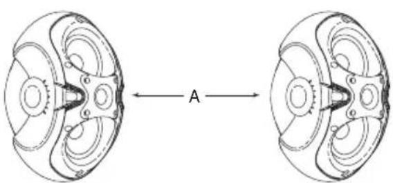
Listed and illustrated below are the parts included in each boxed pair of EVID™ speakers.
| erugiF ytitnauQ traP | ||
| A 2 metsySrekaepS | ||
| B AM | TM | IymessA |
| C 2 | ogaLegraL | |
| C | 2 | Small Logo Cap |
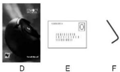
| D | 1 | Owner's Manual |
| E | 1 | Warranty Card |
| F | 1 | AMTM log |
natural_image
Diagram of two mechanical components with labeled cross-section A, showing internal gear-like structures (no text or symbols)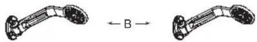
natural_image
Two identical mechanical linkages with a labeled arrow indicating direction (no text or symbols present)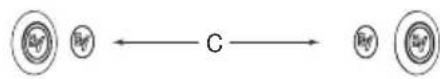
natural_image
Abstract geometric diagram of an open box with radiating lines, no text or symbols presentFigure 1: EVID™ Components
EVID™ Product Family Product Feature Identification
| ecnadepmlmho | ||
| Part No. | Model | Description |
| 100-540103 | Dual 3.5" Full-Range Shielded (Black) | |
| 301045-002 | 3.2w | Dual 3.5" Full-Range Shielded (White) |
| 100-640103 | Dual 4" Full-Range Shielded (Black) | |
| 301046-002 | 4.2w | Dual 4" Full-Range Shielded (White) |
| 100-740103 | Dual 6" Full-Range Shielded (Black) | |
| 200-740103 | Dual 6" Full-Range Shielded (White) | |
| 70-Volt/100-Volt Equipped Units | ||
| Part No. | Model | Description |
| 300-540103 | Dual 3.5" Full-RangeShielded (Black) | |
| 400-540103 | Dual 3.5" Full-RangeShielded (White) | |
| 300-640103 | Dual 4" Full-RangeShielded (Black) | |
| 400-640103 | Dual 4" Full-RangeShielded (White) | |
| 300-740103 | Dual 6" Full-RangeShielded (Black) | |
| 400-740103 | Dual 6" Full-RangeShielded (White) | |
| Subwoofers | ||
| Part No. | Model | Description |
| 301048-001 | 12.1 | 12" Dual Input (Black) |
| 301048-002 | 12.1w | 12" Dual Input (White) |
Illustrated below are the major components of the EVID™ Series full-range speakers.
A. Shielded dual woofers
B. Coherent Coverage Waveguide horn (4.2 and 6.2 only)
C. Dual low-frequency ports
D. Treated woofer cones
E. Durable zinc-plated steel grille (not shown)
F. Cast aluminum Strong-Arm-Mount™ (SAM™)
G. Over 100 degrees of swing; 90 degrees of rotation
H. Simple keyed socket head adjustments
I. Titanium dome tweeters with neodymium magnet structures
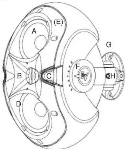
Figure 2: EVID ^TM Features (Front)
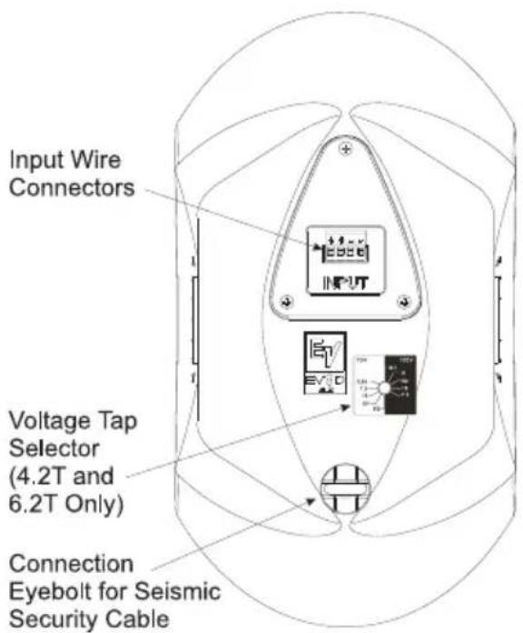
Figure 3: EVID ^TM Features (Back)
SAM™ (Strong-Arm-Mount™) System
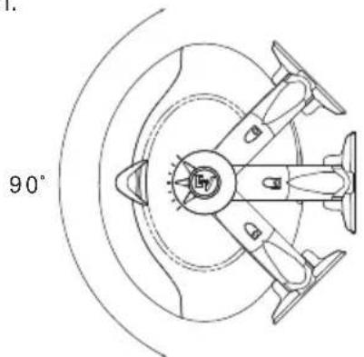
EVID™'s SAM™ system (Strong-Arm-Mount™) excels at meeting the four requirements for mounting FGM/BGM systems: simple, quick, versatile, and reliable. Three easy steps and you are done: Attach the surface bracket to the wall or ceiling; attach the EVID™ enclosure to the bracket with the socket-head bolt; aim the enclosure and tighten the bolt. SAM™ allows greater flexibility for aiming than ball-type mounts that limit range of motion when not on center. Typical ball designs have limited rotation when pointing straight ahead, and even that is reduced when the enclosure contacts the wall and is moved off axis. By contrast, SAM™ allows full rotation even at full sweep. Figure 4 shows SAM™'s range of rotation (note that EVID™'s curved cabinet allows it to rotate much further [90°] than a rectangular or trapezoidal box). Figure 5 shows the range of sweep motion left and right on the wall. All three models allow 100° of sidewise motion.
natural_image
Top-down technical drawing of a mechanical component with angular dimension (90°), no visible text or symbolsFigure 4: Rotation Range (90°)
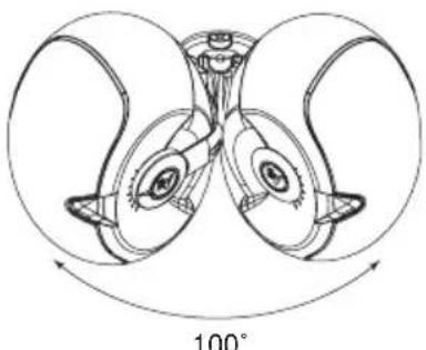
natural_image
Diagram of a symmetrical mechanical or optical component with two petal-like structures and a central axis, labeled 100° (no text or symbols on the diagram itself)Figure 5: Sweep Range (100°)
Product Description
Step-by-Step Installation and Wiring (3.2, 4.2, 6.2)
Step 1: Mount the SAM ^TM Bracket to the Wall
The SAM ^™ bracket can be mounted on either side of the speaker, enabling optimal configuration for any installation. Determine whether the bracket should be mounted on the left or right side of the speaker before you bolt the speaker to the bracket. It is best to mount the bracket on the side away from the direction in which the speaker will be aimed. This ensures that the full swing angle is available for aiming on that side and provides easier access to the swing tightening bolt on the wall bracket (see Fig. 10, Step 3). For safety, make sure the mounting surface can support more than the speaker's weight! Use only industry-accepted fasteners and mounting methods when mounting the bracket. Consult an expert if you are not sure. Read steps 2 and 3 before wiring the speaker in step 4.
For standard vertical installation mount the SAM ^™ bracket as shown in Figure 6. For horizontal mounting configurations, mounting the bracket on the bottom side (as in Figure 7) is easiest and safest, and allows the speaker to be mounted closer to the ceiling.
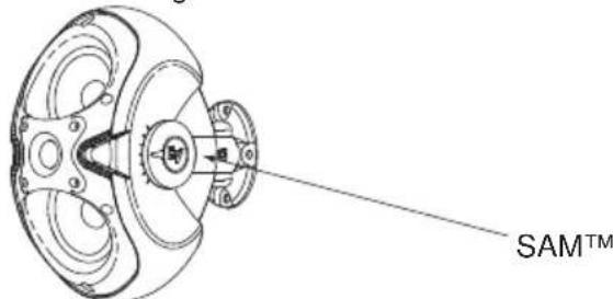
Figure 6: SAM ^TM Mounted on Side

Figure 7: SAM ^TM Mounted on Bottom
Product Description
Step 2: Select Wattage Tap (Models 4.2t and 6.2t Only)
Before mounting the speaker to the bracket, select the proper wattage tap setting for your installation. The wattage selector switch is located at the rear of the speaker below the input terminal panel.
The EVID ^TM 4.2t and 6.2t include a switch for selecting the power taps. The EVID ^TM 3.2t has a single power tap.
EVID™ 3.2t
A single (non-selectable) power tap rated at 5W@70V and 10W@100V.
EVID™ 4.2t
The power taps are 30W, 15W and 7.5W at both 70.7V and 100V, with a 3.7W tap for 70.7V only, as well as an 8 ohm transformer bypass setting.
EVID™ 6.2t:
The power taps are 60W, 30W and 15W at both 70.7V and 100V, with a 7.5W tap for 70.7V only, as well as an 8 ohm transformer bypass setting.
The taps for the models listed above are selected by a rotary switch on the back panel. A guide on the back of each speaker shows which switch positions to use for the power settings at 70V and 100V.
Figure 8 below illustrates the settings for the 4.2t and 6.2t.
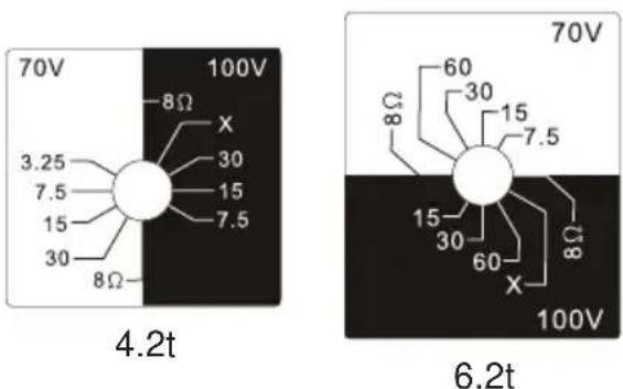
Figure 8: Wattage Taps (4.2t & 6.2t)
Step 3: Mount the Speaker to the SAM ^TM Bracket
Attach the speaker to the SAM ^TM bracket with the socket head bolt B, as shown in Figure 9.
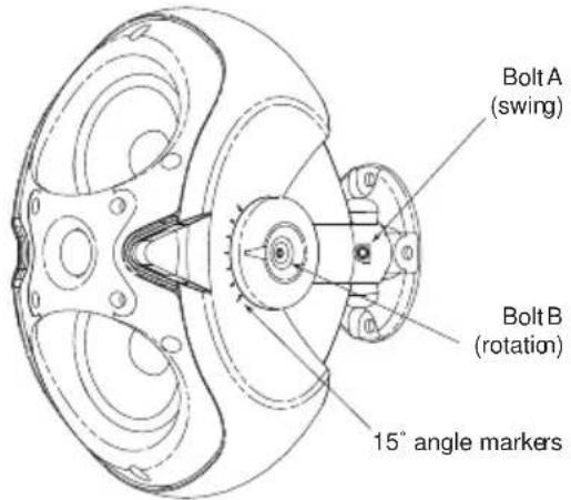
Figure 9: Tighten Socket Head Bolts
Using the provided security tool, tighten the two socket head bolts shown in Fig. 9. Select the proper horizontal angle and secure it by tightening Bolt A to the proper torque listed in Fig. 10. Then select the proper vertical angle and secure it by tightening Bolt B. Use the 15^ angle markers as your guide (see Fig. 9). Attach both logo caps as shown in Figure 11 after tightening and securing the speaker.
| Model Torque |
| EVID 3.2 20-30 in-lbs (2.3-3.4 N-m) |
| EVID 4.2 30-50 in-lbs (3.4-5.2 N-m) |
| EVID 6.2 70-90 in-lbs (7.9-10.2 N-m) |
Figure 10: Recommended Torque Settings for Bolt A
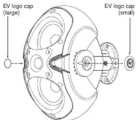
Figure 11: Attach Logo Caps
Step 4: Attach the Wiring to the Terminal Connector and Wire the Speaker
The 4-pin phoenix-style plug-in connector provides for a pass-thru audio connection to daisy-chain a line of speakers. Insert the bare end of wire into the appropriate connector terminals as described below. For parallel wiring, see Figure 12. When one input connector is removed, subsequent speakers will remain connected. For daisy-chaining, see Figure 13. When one input connector is removed, subsequent speakers will be disconnected. Screw down the hold-down screw until tight, using a small screwdriver. See Figure 14. The connector accepts up to 12 gauge wire.
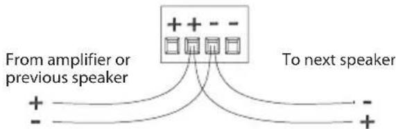
Figure 12: Parallel Wiring
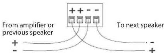
Figure 13: Daisy-Chain Wiring
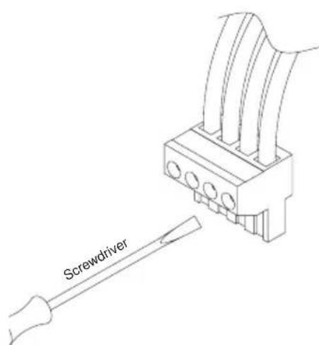
Figure 14: Tighten With Screwdriver
Product Description
Step 5: Secure the Seismic Tab Connection Point
The rear of the enclosure includes an eyebolt for connection to a seismic restraint. Connect it to a properly rated hardware fitting that is securely installed independently of the SAM ^™ bracket. Even if your local construction code does not require the installation of secondary support, its use is highly recommended for further security.
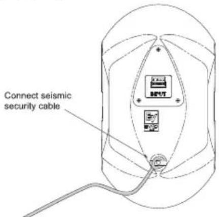
Figure 15: Secure Seismic Security Cable
Step 6: Test System Operation After all connections are made, test the complete system operation. Appendix C (page 14) contains a troubleshooting table to assist in locating many speaker-related problems.
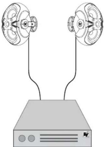
natural_image
Diagram of two connected devices with circular components, no text or symbols presentFigure 16: EVID™ System
EVID™ Owner's Manual
Product Description
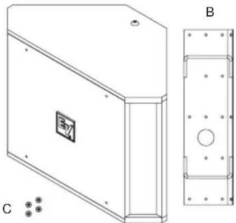
Packing List (12.1 Subwoofer)
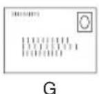
Below is the list of parts included with the EVID™ 12.1 subwoofer. The parts are illustrated in Figure 17.
| Figure | Quantity | Part |
| A | 1 | EVIDTM 12.1 Subwoofer |
| B | 1 | Wall/Corner Mounting Bracket |
| C | 2 | Speaker Mounting Clips |
| D | 4 | Rubber Mounting Feet |
| E | 1 | Eyebolt |
| F | 1 | Owner's Manual |
| G | 1 | Warranty Card |
A
natural_image
Technical line drawing of a rectangular electronic enclosure with mounting holes and a side view showing internal components (no text or symbols)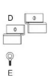


natural_image
Abstract geometric illustration of an open box with radiating lines, no text or symbols presentFigure 17: EVID™ 12.1 Components Figure 19: EVID
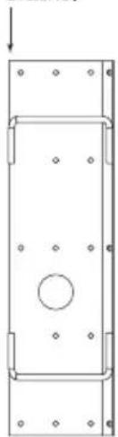
Product Feature Identification
The 12.1 subwoofer comes with a dual-mode mounting bracket that enables the unit to be easily mounted at either a wall/wall (corner) or on a wall/ceiling (midwall) junction. The included forged steel eyebolt provides the installer a solid attachment point for a safety line. The 12.1 subwoofer may also be safely installed protruding just 2 3/4" down through a standard suspended ceiling grid. See installation instructions.
Illustrated below are the major components of the EVID™ Series 12.1 subwoofer.
Dual-mode mounting bracket
natural_image
Pure technical line drawing of a rectangular frame with bolt holes and a central circular hole, no text or symbols present.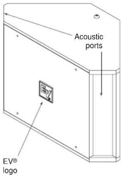
Figure 18: EVID™ 12.1 Features (Front)
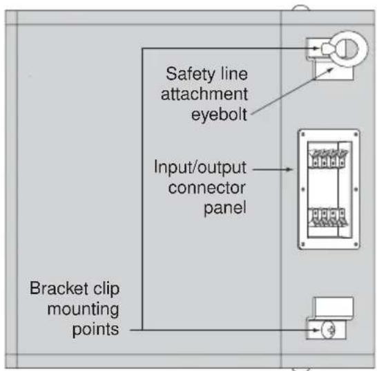
^TM 12.1 Features (Back)
Step-by-Step Installation and Wiring (12.1 Subwoofer)
Step 1: Mount the Bracket
The mounting bracket can be installed two ways (see Figures 20 and 21), allowing optimal configurations for installations.
Leave 1.5" of space between the bracket and the ceiling when installing in a corner!
Attach the bracket to the wall with suitable fasteners screwed into structural members in the wall. Remember: It is the installer's responsibility to insure that the structure can safely support the load.
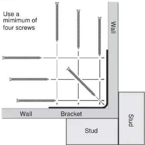
Figure 20: Corner Installation (Top View)
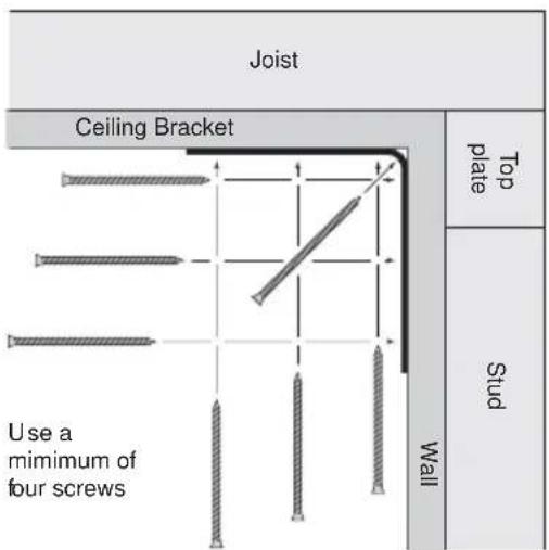
Figure 21: Midwall Installation (Side View)
Product Description
Step 2: Install the Safety Line Using accepted safe rigging practices, secure one end of a suitable safety line (use cable, not chain, which will rattle) to a strong, secure point above the speaker, a point that can withstand the shock of the falling speaker. This is especially important in public spaces constructed with light-gauge steel studs. Do not attach the safety line to the bracket! The safety line should prevent the speaker from falling if the bracket tears loose from the wall. Secure the other end to the eyebolt that is fully threaded into the enclosure.
Step 3: Wire the Speaker
The amplifier and satellite speakers are wired as shown in Figure 22. It is highly advisable to support the unit while these connections are being made. Connect all wires to the speaker at the back terminal plate observing proper polarity of the connections. The push-terminals accept stranded wire up to 14 gauge. When using two satellites, wire the speakers directly into the output terminals of the panel. Four satellites may be connected either as two pairs directly to the output terminals or with daisy-chain wiring as in Figure 23.
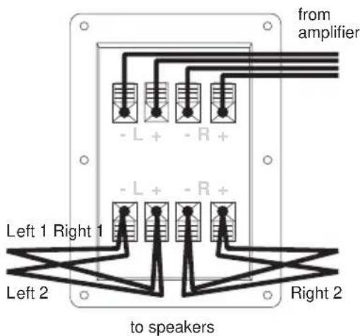
Figure 22: Direct Wiring Plan
Product Description

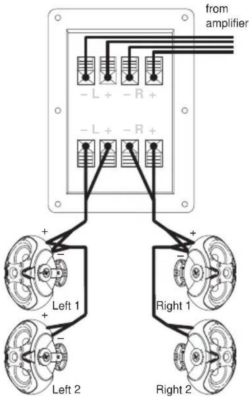
Figure 23: Daisy-Chain Wiring Plan
Step 4: Mount the Speaker to the Bracket
First remove the two Phillips-head screws on the rear of the enclosure. Use the supplied eyebolt to mount one mounting clip to the top of the speaker as shown in Figure 24. Check to make sure that the wiring connections to the amplifier and the satellite speakers are correct and secure.
For corner mounting
Attach the four rubber mounting feet to the front side edges, and secure the safety line to the eyebolt. Lift the enclosure up to the ceiling and center it back it into the corner until it touches the bracket rungs, then carefully lower it so the top clip hooks over the top rung of the bracket (1). Insert one of the 3/8-16-thread Phillips-head screws through the remaining clip and, with the clip pointing up, thread the screw finger-tight into the lower mtg. hole on the enclosure (2, 3). Level the clip and tighten securely with a #3 right-angle Phillips screwdriver.
Even though the enclosure hangs from the top clip, always install the lower one to secure against possible disengagement of the top clip. Straighten the EV® logo and press firmly at its center to seat it securely into its mounting hole.
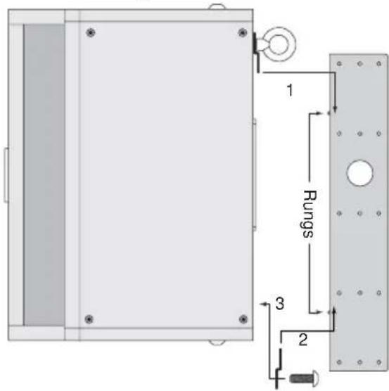
Figure 24: Corner Mounting
For midwall mounting
Attach the four rubber mounting feet inside the corners on the side of the enclosure that will be against the wall and attach the safety line to the eyebolt. Insert one of the 3/8-16-thread Phillips-head screws through the remaining clip and keep it within arm's reach. Lift the enclosure up to the ceiling and bring its back into contact with the bracket rungs. Slide the enclosure sideways to engage the clip over one bracket rung (1) and, while holding it tight against both rungs, insert the 3/8-16-thread screw with its clip into the remaining mounting hole so the clip engages the remaining bracket rung (2, 3). Finger-tighten the screw and straighten the clip. The enclosure may now be released. It will slide down the rungs until the four rubber feet are snug against the wall. Using a #3 right-angle Phillips screwdriver, securely tighten the second Phillips-head screw. Gently rotate the EV® logo a quarter turn and press firmly at its center to seat it securely into its mounting hole. See Figure 25 on p. 10.
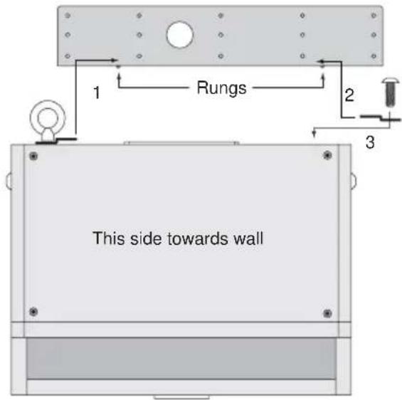
Figure 25: Midwall Mounting
Mounting through a suspended ceiling grid
On the rear of the enclosure install and tighten two 3/8-16-thread forged steel eyebolts (one is included) with a 3/8" flat washer under each. Cut two pieces of ordinary drop ceiling L angle (wall track) 23 3/4" long and screw them to the top and bottom of the enclosure with 3/4"-long sheet metal screws, as shown in Figure 26. Connect all the wires and suspend the enclosure, face down, by the eyebolts in accordance with accepted safe rigging practice. Adjust the length of the rigging cables so the tips of the installed L angles just rest on the ceiling cross-tees. This stabilizes the enclosure from rocking. Trim the ceiling panel to fit the new opening(s) and drop into place. It is the installer's responsibility to assure that the chosen rigging points are strong enough to support the load. Warning: Never try to install this speaker in a suspended ceiling without proper rigging support! Floor Mounting
The EVID™ 12.1 may be placed directly on the floor in a corner or on its side along a straight wall by simply attaching the four rubber mounting feet to the side that will sit on the floor.
Product Description
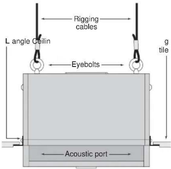
Figure 26: Attach L-Angles to Speaker
Step 5: Test System Operation After all connections are made test the complete system operation. Appendix C on p. 14 contains a troubleshooting guide to assist in locating a variety of speaker related problems.
Safety Agency Compliance
The EVID™ 12.1 bracket system has successfully passed EIA 636 at a safety factor of 8:1. The bracket system is intended to support the EVID™ 12.1 only. Do not use it for any other purpose. Never set anything on, or hang anything from, the EVID™ 12.1 enclosure when using this bracket.
For a copy of the model-specific CE Declaration of Conformity, contact Electro-Voice at the address listed at the end of this manual.
Maintenance
Your EVID™ system has been designed and manufactured to provide years of durability and reliable service. No routine maintenance is necessary. Units may be cleaned by wiping with a soft, damp cloth. Never use solvents or harsh cleaning agents of any kind.
Electro-Voice® products are guaranteed against malfunction due to defects in materials or workmanship for a specified period, as noted in the individual product-line statement(s) below, or in the individual product data sheet or owner's manual, beginning with the date of original purchase. If such malfunction occurs during the specified period, the product will be repaired or replaced (at our discretion) without charge. The product will be returned to the customer prepaid.
Exclusions and Limitations
The Limited Warranty does not apply to: (a) exterior finish or appearance; (b) certain specific items described in the individual product-line statements below, or in the individual product sheet or owner's manual; (c) malfunction resulting from use or operation of the product other than as specified in the product data sheet or owner's manual; (d) malfunction resulting from misuse or abuse of the product; or (e) malfunction occurring at any time after repairs have been made to the product by anyone other than Electro-Voice® Service or any of its authorized representatives.
Obtaining Warranty Service
To obtain warranty service, a customer must deliver the product, prepaid, to Electro-Voice® Service or to any of its authorized service representatives, together with proof of purchase of the product in the form of a bill of sale or receipted invoice. A list of authorized service representatives is available from Electro-Voice® Service at 12000 Portland Avenue, Burnsville, MN 55337. Ph: (877) 863-4166.
Incidental and Consequential Damages Excluded
Product repair or replacement and return to the customer are the only remedies provided to the customer. Electro-Voice® shall not be liable for any incidental or consequential damages including, without limitation, injury to persons or property or loss of use. Some states do not allow the exclusion or limitation of incidental or consequential damages, so the above limitation or exclusion may not apply to you.
Other Rights
This warranty gives you specific legal rights, and you may also have other rights which vary from state to state.
Speakers and Electronics
Electro-Voice® Speakers and Speaker Systems are guaranteed against malfunction due to defects in materials or workmanship for a period of five (5) years from the date of original purchase. The Limited Warranty does not apply to burned voice coils or malfunctions such as cone and/or coil damage resulting from improperly designed enclosures. Electro-Voice® active electronics associated with the speaker systems are guaranteed for three (3) years from the date of original purchase. Additional details are included in the Uniform Limited Warranty statement.
Installation Examples
The EVID ^™ Series is a product family with the flexibility to fit the requirements of many different applications. Listed below are some suggested combinations for systems using the 12.1.
- Rich, full-sounding low-level background music and paging in a quiet restaurant, office, or retail space: two EVID™ 3.2s in parallel on each output of a 12.1.
- Moderate-level music and paging in a sports bar/restaurant or upbeat retail space: two EVID™ 4.2s in parallel on each output of a 12.1.
- Higher-level foreground music in bass-heavy applications such as dance floors, amusement arcades, or loud bars: use one EVID™ 6.2 on each output of 12.1. EVID™ systems may be used together. For example, a large hotel might use eight 3.2s and two 12.1s in the dining room, eight 4.2s and two 12.1s in the lounge, four 6.2s with two 12.1s surrounding the dance floor, 6.2s around the pool, 6.2s or 4.2s with or without 12.1s in the lobby, and 3.2s in the corridors.
Crossover Frequency and Impedance
The EVID™ 12.1 is designed to be used as a passive subwoofer. No additional amplifiers or signal processors are required to achieve full benefit of the 12.1's performance. The built-in passive stereo crossover sends the lowest notes of both stereo channels to the 12" dual-coil bass driver and reduces the amount of low frequencies sent to the satellite speakers. This allows them to play louder and cleaner while presenting a more even, amplifier-friendly impedance load than if all the speakers were connected in parallel. The EVID™ 12.1's crossover tunes a combination of electrical and acoustic characteristics to complement the response of the full-range EVID™ models. The crossover point is set electrically in the 160Hz range with a topology that enables the nominal system impedance to be determined by the number of satellites per channel.
Using a Separate Amplifier Channel for the 12.1
In certain specialized applications, it may be desirable to drive the subwoofer with a separate amplifier channel. In these applications the active crossover point must be at or below 160Hz so as not to interfere with the built-in passive cross-over. Both sections (left and right inputs) must be connected in parallel (4 ohm system impedance) when operating as a mono device. No load resistors are necessary on the hi-pass outputs.
Characteristics of All Subwoofers
While subwoofers do radiate sound omnidirectionally (in all directions) and the sound is generally non-localizable (one can't hear exactly where it comes from), subwoofer sound level still drops off the farther one moves from the subwoofer. The highest output and best room loading are accomplished with the subwoofer mounted in a corner at a three-boundary junction (wall/wall/ceiling or wall/wall/floor, an arrangement also referred to as 1/8 space). Mounting at a two-boundary junction (wall/ceiling, or 1/4 space) produces three dB less output, and mounting in the middle of a room in the ceiling (1/2 space) reduces output still another three dB.
Subwoofers produce large amounts of long-wavelength low-frequency energy. Every object has its own resonant frequency, and long wavelengths tend to excite large objects (like walls, floors, doors and ceiling panels). Anything loose in or on a ceiling or wall will buzz or rattle as a subwoofer's level is increased. Most of these can be isolated and fixed with small, strategically placed bits of foam tape. Others may require driving additional nails or screws and perhaps some caulking to dampen their sympathetic movement. Be aware that as bass levels increase, so does the likelihood of rattles and buzzes.
Appendix B: Painting the EVID™ Speakers

The 12.1 subwoofer is a painted wood enclosure which can easily be repainted.
Painting Process
(3.2, 4.2, 6.2)
The EVID ^™ 3.2, 4.2 and 6.2 are made of high-impact ABS, which accepts a wide variety of paints.
- Remove the grille and mask the baffle.
- Clean the cabinet and grille by rubbing the speaker with a lightly dampened cloth. Do not, however, use abrasives such as sandpaper or steel wool. Never use gasoline, kerosene, acetone, MEK, paint thinner, harsh detergents, or other chemicals, as these agents may cause permanent damage to the enclosure.
• After cleaning, apply latex or enamel paint. Spraying is recommended
Painting the Grille
- Painting the grille requires spray painting. If the grille is rolled or brush painted, the mesh may become clogged with paint and poor sound quality may result.
Painting Process
(12.1 Subwoofer)
- Remove the four screws securing the front hatch and lift off the hatch panel. Carefully twist and lift off the EV® logo and set it aside.
-
The foam grille blocks are held in place by sharp pins protruding through the baffle board. Note the relative position of the foam and carefully lift the blocks off the pins. Mask around the input panel with tape and tape a piece of heavy paper over the woofer. It is not necessary to remove any components.
-
Clean the cabinet, bracket and clips by rubbing with a lightly dampened cloth. Do not use abrasives such as sandpaper or steel wool. Never use gasoline, kerosene, acetone, MEK, paint thinner, harsh detergents, or other chemicals, as these agents may cause permanent damage to the enclosure.
- After cleaning, apply two or more two thin coats of either latex or oil-based paint. Spraying is recommended, but a brush and small roller work very well. It is not necessary to paint all the way up to the woofer. Only the visible surfaces need to be painted: the hatch front and side edges, the exposed enclosure surfaces down to the hatch gaskets and about halfway under where the foam blocks sit. Likewise, the back sides of the bracket and clips need not be painted. The hatch screw heads may be painted, if desired.
- When the paint is thoroughly dry, carefully unmask everything. Replace the foam blocks, pressing them gently down onto the sharp pins. Replace the hatch cover and tighten the four screws. Locate the small center hole, properly orient the EV® logo, and press it firmly into place at its center to reseat it in the mounting hole.
| melborP | s | esuaCelbissoP | |
| dnuoSoN | Amplifier | Connect a known working test speaker to the amplifier outputs. If there is no sound, check that all electronics are on, the signal routing is correct, the source is active, the volume is turned up, and so on.Correct/Repair/Replace as necessary. If there is sound, the problem is in the wiring. | |
| iW | Verify that you have connected the correct wire pairs to the amplifier. Play something at low level through the amplifier (for example, from a CD player or tuner). Connect the test speaker in parallel with the malfunctioning line. If the the sound has gone or is very weak, the line has a short in it (possibly a severe scrape, pinch, or staple puncture). If the sound level is normal the wire is open (possibly a cut wire or missed connection). Using the test speaker, move down the line and test each connection/junction until you find the problem and correct it. Observe proper polarity. | ||
| If you are using the 12.1 subwoofer, use the test speaker to verify that you have the inputs and outputs connected to the correct wires. If the subwoofer input panel is not correctly wired, there will be little or no sound. Observe proper polarity. | |||
| eboPycneuRqe esnopseR | Speakers Wired Out-of-Polarity | When two speakers are connected out of polarity (out of phase), the low frequencies will cancel each other acoustically. Carefully observe the wire markings or tracers on your speaker wires. Verify that the amplifier (+) terminal is connected to the red speaker terminals and the amplifier (-) terminal is connected to the black speaker terminals. | |
| Improperly Wired ehaBrowus | Using a test speaker as described above, verify that all amplifier and speaker wires are connected to their proper terminals with the correct polarity. Reversing just one set of amplifier wires can cut out all bass output from the subwoofer. | ||
| Intermittent Output or Distortion | FouAConnection | Check all connections at amplifier and speakers to ensure they are clean and tight. If the problem persists, it may be in the amplifier or wiring. See other actions above. | |
| esMar gzu Hissing, Humming | Defective Amplifier or other Electronic oC veD Bsahcus | If the noise is present but no program material is playing, the likely cause is the signal chain in the electronics. Evaluate each component as necessary to isolate the problem. | |
| yEop dnoorG pooLdnuorG | Check and correct the system grounding, as required. | ||
| If none of the suggestions below solves your problem, contact your nearest Electro-Voice service center or Electro-Voice distributor. | |||
Specification 3.2/3.2t 4.2/4.2t
| Frequency Response ^1 (-10 dB) | 85 Hz-20 kHz 65 Hz-20 kHz | |
| Power Handling ^2 | 150 watts 200 watts | |
| Sensitivity ^3 | 87 dB, 1 W/1 m 90 dB, 1 W/1 m | |
| Impedance 8 ohms 8 ohms | ||
| Max SPL 104 dB 111 dB | ||
| Horizontal Coverage ^4 | 120° 100° | |
| Vertical Coverage ^4 | 110° 90° | |
| LF Transducer 2 × 3.5" (90 mm) | 2 × 4" (90 mm) | |
| HF Transducer | .75" (20 mm) | 1" (25 mm) |
| Protection | Full System | Full System |
| Suspension/ | Multi-Axis | Multi-Axis |
| Swing × Rotation | 100° × 45° | 100° × 45° |
| Terminals 4-Pin Phoenix-Style | 4-Pin Phoenix-Style | |
| Plug-In Connector | Plug-In Connector | |
| Enclosure Material | ABS (paintable) ABS (paintable) | |
| "t"-version wattage taps | 5 W 70 V/10 W 100 V | 70 V: 3.25 W70 V/100 V: 7.5 W, 15 W, 30 W,8 ohm Bypass |
| Dimensions | 9.2" × 5.1" × 6.5" | 12.2" × 6.9" × 8.5" |
| 234 × 127 × 165 mm | 310 × 175 × 216 mm | |
| Net Weight (each) 3.3 lbs (1.5 kg) | 8.5 (3.9 kg) | |
| Shipping Weight (pair) | 8.6 lbs (3.9 kg) | 19 lbs (8.6 kg) |
| Included Accessories | SAM, hex key | SAM, hex key |
^1 Half space (wall mounting)
^2 Long Term Program Rating, 3 dB greater than continuous noise pink noise rating
^3 Avg. Half Space (wall mounting)
^4 When mounting with long axis in vertical plane
Specification 6.2/6.2t 12.1
| Frequency Response ^1 (-10 dB) | 62 Hz-20 kHz 40 Hz-140 Hz | |
| Power Handling ^2 | 300 watts 175/175 watts | |
| Sensitivity ^3 | 95 dB, 1 W/1 m 100 dB, 1 W/1 m | |
| Impedance 8 ohms 8 ohms | ||
| Max SPL 116 dB 122 dB | ||
| Horizontal Coverage ^4 | 100° N/A | |
| Vertical Coverage ^4 | 90° N/A | |
| LF Transducer 2 × 6" (90 mm) | 12" (90 mm) high-excursion dual voice coil | |
| HF Transducer | 1" (25 mm) | N/A |
| Protection | Full System | N/A |
| Suspension/Swing × Rotation | Multi-Axis100° × 45° | N/AN/A |
| Terminals | 4-Pin Phoenix-StylePlug-In Connector | Spring |
| Enclosure Material | ABS (paintable) MDF (steel fastener reinforced) | |
| "t"-version wattage taps | 70 V: 7.5 W70 V/100 V: 15 W,30 W, 60 W, 8 ohm Bypass | N/A |
| Dimensions | 16.5" × 9" × 11.75"419 × 228 × 298 mm | 16.25" × 23" × 12"412 × 584 × 305 mm |
| Net Weight (each) 12 lbs (5.3 kg) | 40 lbs (18.1 kg) | |
| Shipping Weight (pair) | 27 lbs (12.3 kg) | 48 lbs (20.0 kg) |
| Included Accessories | SAM, hex key | Mounting brackets, hardware |
^1 Half space (wall mounting)
^2 Long Term Program Rating, 3 dB greater than continuous noise pink noise rating
^3 Avg. Half Space (wall mounting)
^4 When mounting with long axis in vertical plane