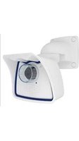
M25M - Security Camera Mobotix - Free user manual and instructions
Find the device manual for free M25M Mobotix in PDF.


| Type | 5MP Allround Security Camera (Indoor/Outdoor) |
| Image Sensor | 1/2.5" CMOS, 5 Megapixels (2592x1944) |
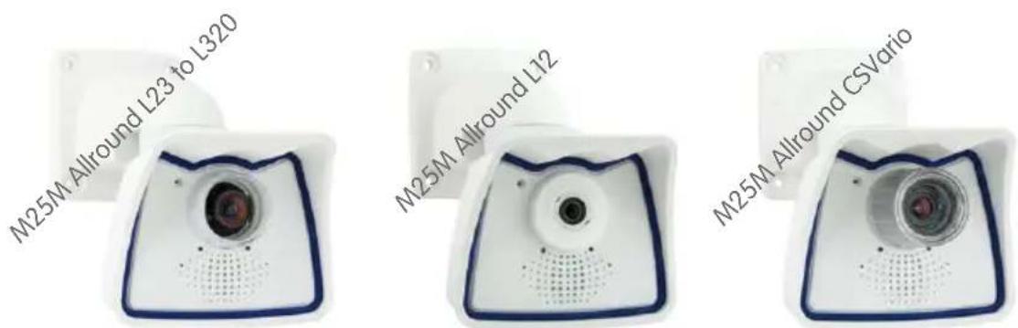
| Lens Options | 7 interchangeable lenses: L12 (180° fisheye), L23 (92°), L25 (82°), L38 (55°), L51 (40°), L76 (27°), L160 (13°), L320 (7°), plus CSVario |
| Max. Frame Rate | 30 fps (VGA/MEGA MxPEG), 10 fps (5MP MxPEG) |
| Video Compression | MxPEG, M-JPEG, H.264 |
| Power Supply | Power over Ethernet (PoE) IEEE 802.3af, variable PoE class 2-3 |
| Power Consumption | Typical < 4.5 W |
| Operating Temperature | -30°C to +50°C (-22°F to +122°F) |
| Protection Class | IP66 (dustproof, water jet resistant) |
| Internal Storage | Pre-installed MicroSD card (SDXC), capacity varies; supports DVR recording |
| Audio | Integrated microphone and speaker for two-way communication |
| Dimensions (Wall Mount) | 140 x 189 x 222 mm (5.5 x 7.4 x 8.7 in) |
| Weight (with Standard Lens) | Approx. 772 g (1.7 lb) |
| Mounting | Wall, ceiling, or pole via included VarioFlex mount |
| Software (Free) | MxEasy, MxControlCenter, MOBOTIX App (iOS/Android) |
| Video Analysis | Video Motion Detection, MxActivitySensor (Secure models), virtual PTZ |
| Security Features | HTTPS/SSL, IP address filter, IEEE 802.1X, user/group management, shock detector |
| Accessories | Lens cover with glass, pole mount, overvoltage protection, interface boxes (MX-232-IO, ExtIO, GPS, etc.) |
| Maintenance | Clean lens with lint-free cloth; drill drainage holes to prevent condensation if needed |
| Manufacturer | MOBOTIX AG, Germany |
Frequently Asked Questions - M25M Mobotix
User questions about M25M Mobotix
0 question about this device. Answer the ones you know or ask your own.
Ask a new question about this device
Download the instructions for your Security Camera in PDF format for free! Find your manual M25M - Mobotix and take your electronic device back in hand. On this page are published all the documents necessary for the use of your device. M25M by Mobotix.
USER MANUAL M25M Mobotix
natural_image
White camera module with blue frame and a small blue card showing 880 micro drive (no text or symbols on device)More Camera For Less. Guaranteed!
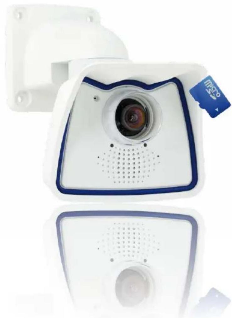
The M25M series from MOBOTIX offers extremely compact, cost-effective and exceptionally powerful 5MP allround cameras with the widest range of lenses, including panorama version. Fully equipped with IP66-certified housing and long-term internal storage on a MicroSD card.
Innovations - Made in Germany
The German company MOBOTIX AG is known as the leading pioneer in network camera technology and its decentralized concept has made high-resolution video systems cost efficient.
MOBOTIX AG • D-67722 Langmeil • Phone: +49 6302 9816-103 • Fax: +49 6302 9816-190 • sales@mobotix.com
THE MOBOTIX INFORMATION CHANNELS
MOBOTIX
Support on the MOBOTIX Website www.mobotix.com/other/Support

The MOBOTIX Video Tutorials www.mobotix.com/other/ Support/Tutorials

Seminars on MOBOTIX Campus www.mobotix.com/other/ Partners/Seminars
YouTube
The MOBOTIX YouTube Channel www.youtube.com/MOBOTIXAG



MOBOTIX Seminars
MOBOTIX offers inexpensive seminars that include workshops and practical exercises. For more information, visit www.mobotix.com > Seminars.
Copyright Information
All rights reserved. MOBOTIX, the MX logo, MxControlCenter, MxEasy and MxPEG are trademarks of MOBOTIX AG registered in the European Union, the U.S.A., and other countries. Microsoft, Windows and Windows Server are registered trademarks of Microsoft Corporation. Apple, the Apple logo, Macintosh, OS X, iOS, Bonjour, the Bonjour logo, the Bonjour icon, iPod and iTunes are trademarks of Apple Inc. registered in the U.S.A. and other countries. iPhone, iPad, iPad miniand iPod touch are Apple Inc. trademarks. Linux is a trademark of Linus Torvalds. All other marks and names mentioned herein are trademarks or registered trademarks of the respective owners.
Copyright © 1999-2015 MOBOTIX AG, Langmeil, Germany. Information subject to change without notice!
Download the latest version of this and other manuals as PDF files from www.mobotix.com > Support > Manuals.
CONTENTS
1 Product Overview 10
1.1 M25M Allround 10
1.1.1 General Product Characteristics 10
1.2 M25M with Special Lens Hemispheric L12 20
1.2.1 Advantages and New Features 26
1.2.2 Decentralized Video System 28
1.2.3 Green IP Video 30
1.3 Technical Specifications 32
1.3.1 Lens Options 32
1.3.2 Camera Variants – Lenses, Hardware, Image Formats 34
1.3.3 Camera Variants – Software Features 35
1.3.4 Technical Data 36
1.4 Delivered Parts and Dimensions 38
1.4.1 M25M Camera 38
1.4.2 Dimensions (mm) for Wall Installation 42
1.4.3 Dimensions (mm) for Ceiling Installation 42
1.4.4 Dimensions (mm) of Wall Mount 43
1.4.5 Drilling Template (mm) Wall and Ceiling Mount 43
1.5 Available Accessories 44
1.5.1 Lens Cover with Glass Pane 44
1.5.2 Pole Mount 44
1.5.3 MiniUSB Cable to MiniUSB (Straight/Angled) 44
1.5.4 MiniUSB Cable to MiniUSB (Angled/Angled) 45
1.5.5 MiniUSB Cable to USB-A Socket 45
1.5.6 Ethernet Patch Cable for Bayonet Catch 45
1.5.7 NPA-PoE-Set 45
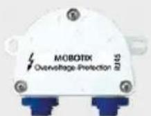
1.5.8 MX-Overvoltage-Protection-Box 46
1.5.9 MX-NPA-Box 46
1.5.10 MX-GPS-Box 46
1.5.11 MX-232-IO-Box 47
1.5.12 ExtIO Expansion Module 47
1.5.13 Mx2wire+ Media Converter 47
1.5.14 Installing Interface Boxes Under a Varioflex Wall Mount 48
1.5.15 Other Accessories 48
1.6 MOBOTIX Software 49
1.6.1 Integrated Camera Software (Firmware) 49
1.6.2 MxControlCenter 50
1.6.3 MxEasy 51
1.6.4 MOBOTIX App 52
2 Installation 54
2.1 Preparing the Installation 54
2.1.1 Mounting Options: Wall, Ceiling, Pole 54
2.1.2 Mounting with Hemispheric Lens L12 57
2.1.3 Network Connection and Power Supply, UPS 60
2.1.4 Preparing the Camera Connections, MX-Overvoltage-Protection-Box 61
2.1.5 Wiring, Fire Prevention, Lightning and Surge Protection 62
2.2 Mounting the Camera with Wall Mount 63
2.2.1 VarioFlex Wall Mount 63
2.3 Mounting the Camera with Ceiling Mount 67
2.3.1 VarioFlex Ceiling Mount 67
2.4 Mounting the Camera with Pole Mount (Accessory) 71
2.4.1 Pole Mount (MX-MH-SecureFlex-ESWS) 72
2.5 Adjusting the Camera and Exchanging the Lens 76
2.5.1 Adjusting the Camera 76
2.5.2 Correcting the Image Horizon (for L12 Lens Only) 76
2.5.3 Exchanging the Lens 77
2.6 Replacing the MicroSD Card 78
2.6.1 Removing the MicroSD Card 78
2.6.2 Inserting the MicroSD Card 79
2.7 Network and Power Connection 80
2.7.1 Notes on Cable Lengths and Power Supply 80
2.7.2 Network Cabling For M25M With Patch Cables 80
2.7.3 Power Supply Using a Switch 81
2.7.4 Power Supply When Connected Directly to a Computer 82
2.7.5 Power Supply with Power-Over-Ethernet Products 82
2.7.6 Connecting a USB Cable 83
2.7.7 Connecting a Two-Wire MxBus Cable 84
2.7.8 Variable PoE 85
2.7.9 Camera Startup Sequence 86
3 Operating the Camera 88
3.1 Manual and Automatic Operation – Overview 88
3.1.1 Manually Using a Computer in the 10.x.x.x IP Address Range 89
3.1.2 Automatically Using MxControlCenter or MxEasy 90
3.1.3 Automatically Using DHCP 91
3.2 First Images and the Most Important Settings 92
3.2.1 Manually Setting Up the Network Parameters in a Browser 92
3.2.2 First Images and the Most Important Settings in the Browser 94
3.2.3 First Images and Network Parameter Configuration in MxControlCenter 96
3.2.4 First Images and Network Parameter Configuration in MxEasy 101
3.2.5 Starting the Camera with the Factory IP Address 104
3.2.6 Starting the Camera with an Automatic IP Address (DHCP) 105
3.3 Virtual PTZ and Full Image Recording 106
3.3.1 Preparing the Virtual PTZ Function 106
3.3.2 Full Image Recording 108
3.3.3 Special M25M Configuration in the Browser 110
3.4 MicroSD Card Recording 117
3.4.1 Introduction 117
3.4.2 Formatting the MicroSD Card 119
3.4.3 Activating MicroSD Card Recording 120
3.4.4 Accessing Data on the MicroSD Card 121
3.4.5 Deactivating Card Recording 121
3.4.6 Using a MicroSD Card in a Different MOBOTIX Camera 122
3.4.7 Limitations on Warranty When Using Flash Storage Media 122
3.5 Configuration in the Browser 123
3.5.1 Overview 123
3.5.2 General Browser Settings 125
3.6 Additional Notes 127
3.6.1 Protecting the Camera Against Condensation 127
3.6.2 Password for the Admin Menu 128
3.6.3 Permanently Deactivating the Microphone 129
3.6.4 Starting the Camera with the Factory IP Address 129
3.6.5 Resetting the Camera to Factory Settings 129
3.6.6 Activating Event Control and Motion Detection 129
3.6.7 Deactivating Text and Logo Options 129
3.6.8 Deactivating the Camera Reboot 130
3.6.9 Browser 130
3.6.10 Cleaning the Camera and Lens 130
3.6.11 Legal Notes 130
3.6.12 Safety Warnings 131
3.6.13 Online Help in the Browser 132
3.6.14 Declaration of Conformity 132
3.6.15 Disposal 132
3.6.16 Disclaimer 132
Manufacturer 135
natural_image
Close-up of a white and blue camera module with a lens and a micro卡 (no text or symbols visible)
Legal Notes
Legal aspects of video and sound recording: You must comply with all data protection regulations for video and sound monitoring when using MOBOTIX products. Depending on national laws and the installation location of the M25M, the recording of video and sound data may be subject to special documentation or it may be prohibited. All users of MOBOTIX products are therefore required to familiarize themselves with all valid regulations and comply with these laws. MOBOTIX AG is not liable for any illegal use of its products.
© MOBOTIX AG • Security-Vision-Systems • Made in Germany
Safety Warnings
Installation Instructions:
- This product must not be used in locations exposed to the dangers of explosion.
- Make sure to install this product as shown in Chapter 2, «Installation» of this manual.
- When installing this product, make sure that you are only using genuine MOBOTIX parts and MOBOTIX connection cables.
- Make sure that you are installing this product on a solid surface that provides for a sturdy installation of the fixing elements used.
Electrical installation: Electrical systems and equipment may only be installed, modified and maintained by a qualified electrician or under the direction and supervision of a qualified electrician in accordance with the applicable electrical guidelines. Make sure to properly set up all electrical connections.
Electrical surges: MOBOTIX cameras are protected against the effects of small electrical surges by numerous measures. These measures, however, cannot prevent the camera from being damaged when stronger electrical surges occur. Special care should be taken when installing the camera outside of buildings to ensure proper protection against lightning, since this also protects the building and the whole network infrastructure.
Max. power consumption of attached extension modules: The power consumption of all attached MxBus modules must not exceed 2.5 W. When attaching modules to the MxBus connector and the USB connector, the power consumption of all attached modules must not exceed 3 W, if the camera is powered by PoE class 3. If PoE class 2 is used, the power consumption of all attached modules must not exceed 1 W!
Never touch the lens: Due to the high performance of the M25M, the area of the image sensor can get quite hot, especially when the ambient temperature is also high. This does not affect the proper functioning of the camera in any way. For this reason, the product must not be installed within the reach of persons without the lens cover.
Power off before opening the camera: Make sure the power supply is disconnected before opening the camera (i.e., for installing or replacing sensor modules and SD cards).
Network security: MOBOTIX products include all of the necessary configuration options for operation in Ethernet networks in compliance with data protection laws. The operator is responsible for the data protection concept across the entire system. The basic settings required to prevent misuse can be configured in the software and are password-protected. This prevents unauthorized parties from accessing these settings.
FOREWORD
Dear MOBOTIX customer,
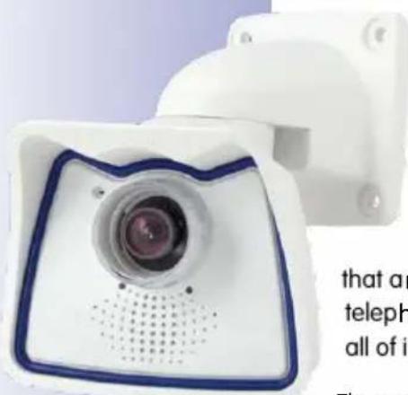
Congratulations on your decision to purchase a professional and modern HiRes network camera "Made in Germany"! The robust and versatile M25M is a cost-efficient and professional mono camera solution with interchangeable lenses for indoor and outdoor applications (IP66). You can select from a wide range of lenses, from Hemispheric to Super Wide-Angle to Tele lenses (now up to 320 mm) and CSVario lens. Add to that the proven advantages that are inherent to the MOBOTIX concept, such as the integrated event, alarm and telephone features and the modern long-term storage directly in the camera with all of its benefits.
The weatherproof MxBus and MiniUSB interfaces of the camera allow attaching MOBOTIX interface boxes and standard devices, such as 3G/UMTS modems, external storage devices, etc. The integrated SD card flash storage is easily exchanged for larger storage requirements, providing for secure long-term storage.
The introduction of the newest image sensor technology with increased light sensitivity in combination with the new HD Premium lenses (f/1.8) provides brilliant images with image sizes of up to 2592x1944 pixels, thus delivering color images of higher quality under low-light conditions. The LPF ("Long-Pass Filter") night variants have been designed for special purposes, such as number plate recognition, for example. The M25M-IT generates HD images (1280x720 pixels).
You can download the MxEasy and MxControlCenter video management software for MOBOTIX cameras and the manuals from the MOBOTIX website: www.mobotix.com > Support > Software Downloads. For the iPad, iPhone and iPod touch iOS devices, MOBOTIX offers the MOBOTIX App, a free-of-charge mobile solution that is easily found when searching for "MOBOTIX AG" in the App Store.
If you have any questions, our support and international sales staff are available at intl-support@mobotix.com from Monday to Friday, 8 am to 6 pm (German time).
We would like to thank you for your trust and wish you all the best with your new MOBOTIX camera M25M Allround!
natural_image
Abstract geometric logo with blue and gray letter M forming a cross (no text or symbols)MOBOTIX
WOBOLIX
© MOBOTIX AG • Security-Vision-Systems • Made in Germany

natural_image
Two-panel image: top shows a person in a purple jacket viewed from behind; bottom shows a nighttime cityscape with illuminated buildings and flags (no readable text or symbols)
natural_image
Two-panel image: top shows a hallway with people and a wall display; bottom shows a snowy mountain scene with smoke rising (no visible text or symbols)
natural_image
Two-panel image showing a blue-tinted aerial view of a forested area and a red curved line over a coastal scene with boats and a dock (no visible text or symbols)
natural_image
Exterior night view of a modern office building with landscaping and a red curved line overlay (no signage or text)
natural_image
Two-panel image showing a person walking on a wet road and a car with a red circle highlighting a bird's head (no visible text or symbols)
natural_image
Close-up of a white and blue digital camera with a circular lens and perforated grille (no text or symbols visible)

natural_image
Close-up of a white plastic device with a central circular component and blue border, labeled 'M25M Allround L12' (no other text or symbols visible)
1 PRODUCT OVERVIEW
1.1 M25M Allround

natural_image
White camera with blue frame and circular lens, partially covered by a blue 'm338' card (no text or symbols on device body)1.1.1 General Product Characteristics
Model Variants

M25M models with L12 and CSVario lens are only available as Secure variants (details see Section 1.3)
The M25M is available as Secure and IT models with different feature sets. By default, the M25M is equipped with either a color or a Black&White image sensor (Day/Night) and an L25 Super Wide-Angle lens (horizontal angle of view of 82°). If desired, the camera can be fitted with one of seven other lenses with horizontal angles of view of 7°, 13°, 27°, 40°, 55°, 92° and 180° or it is available as a special version with CS Vario lens. Every M25M comes with a pre-installed and formatted MicroSD card and a VarioFlex mount for fast and easy installation.
Due to its extreme distortion, the M25M with the L12 Fisheye lens is especially challenging where the adjustment of hardware and software is concerned. For this reason, the lenses
© MOBOTIX AG • Security-Vision-Systems • Made in Germany
of the L12 variant are not interchangeable. The fine-tuning of the lens at the factory is an extremely laborious and precise process and the setting should not be changed any more.
Complete HiRes Video Solutions by MOBOTIX
As opposed to conventional solutions, MOBOTIX cameras with their decentralized approach offer so much more – state-of-the-art, network-based video security technology that increases operating efficiency and yields a high degree of every-day usefulness.
Extraordinary Picture Quality
Image quality is the one key criterion of a security camera. Due to their internal video analysis and data storage capabilities, the decentralized MOBOTIX systems are independent of the available network bandwidth. As a result, the system provides for efficiently storing and managing the video streams of a virtually unlimited number of cameras with the highest resolution at a reasonable cost.
5 Megapixel Image Sensors (5MP)
MOBOTIX cameras possess high-resolution image sensors with 5 megapixel resolution and excellent light sensitivity, which translates into more details when zooming and more clear-cut advantages for every user. By using the 5MP technology in their color and black&white image sensors, MOBOTIX cameras deliver convincing image quality and details even in bad weather and under lowlight conditions. Another important plus: thanks to its internal pre-processing of the image data, the camera can generate video streams with up to 30 frames per second.
5MP Image Format: 5 Times More Detail Than Full HD
The 5MP sensor has a resolution of 2592x1944 pixels on both day and night sensors. This means that the full image information is available in the live image and in the recordings.
Low Light Conditions – No Problem
The maximum resolution of the color and black&white image sensors is 5 megapixels. The higher light sensitivity of the new color image sensors now allow using MOBOTIX color cameras around the clock even when the illumination is low.
MxLEO: Exposure Optimization and Reduced Image Noise
MxLEO – the MOBOTIX Lowlight Exposure Optimization – is an innovative technology that provides an entirely new experience in digital image optimization in all cameras running firmware 4.1.9 and higher. On the one hand, the improved light sensitivity of the MOBOTIX 5MP sensors drastically reduces exposure times. MxLEO, the exposure and image optimization program especially developed for these conditions, on the other hand, generates perceptibly better and more detailed images especially under low-light conditions below 25 Lux. Such conditions are typical at a parking lot at night that is illuminated by regular lights (approx. 10 to 25 Lux). Or in a building after hours, in which the emergency lights are burning (approx. 5 Lux). This significantly reduces motion blur that is typical of longer
© MOBOTIX AG • Security-Vision-Systems • Made in Germany
VarioFlex wall mount with concealed cabling perfectly covers flush-mounted sockets

natural_image
Top-down view of a white circular electronic device with ventilation grille and mounting holes (no text or symbols visible)MOBOTIX ExtIO (Function Extension)
exposure times with little light and thus provides much more image detail (faces, license plates, etc.) for proper identification.
Hemispheric Technology
Thanks to the fisheye technology with integrated distortion correction, MOBOTIX Hemispheric cameras with their L12 lenses provide the perfect overview. Meaningful 180-degree panorama images from wall-to-wall and from the floor to the ceiling don't leave any corners of the room unmonitored. In contrast to other systems, the correction of the distorted hemispheric image happens directly in the camera and not on the computer, thus drastically reducing the size of the image before it is transferred and stored. This approach reduces the network load and allows showing dozens of hemispheric cameras on a computer or a smartphone.
Robust and Maintenance-Free
Thanks to its low power consumption of about 4.5 Watts and the total absence of mechanically moving parts, the M25M models feature a wide operating temperature range of -30 to +50 °C/-22 to +122 °F. Since MOBOTIX cameras neither fog up nor require heating, power can be supplied via the network cabling using standard PoE products according to PoE standard IEEE 802.3af. M25M IT and Secure models are absolutely dustproof and resistant against water jets (IP66). In

natural_image
3D rendering of a robotic arm with articulated joints and a yellow head (no text or symbols visible)combination with the supplied M25M wall and ceiling mount, you can use the camera in outdoor applications and installation over flush-mounted sockets so that the cabling remains perfectly concealed.
A Master of Adaptability
The M25M models are accompanied by an extensive range of easily replaceable and interchangeable lenses and a robust lens protector made of scratchproof special-purpose plastic or glass. Application-optimized options for installation on walls, ceilings and poles, for supplying power, or expanding the functions of the camera are also available. Furthermore, MOBOTIX customers can take advantage of MxEasy or the professional control center software MxControlCenter free of charge and with an unlimited user and camera license. If required, an M25M can even be upgraded to function as a powerful intercom system by adding the MOBOTIX ExtIO module.
High-Resolution Sees More and Costs Less
One M25M equipped with a hemispheric or standard wide angle lens is usually all that is required to monitor either an entire room or the four lanes of a gas station. The high degree of image detail not only reduces the number of required cameras, but also minimizes system costs by reducing the wiring complexity, emergency power requirements and number of recording devices required. All M25M cameras feature direct recording to integrated MicroSD cards or external USB drives and can therefore be used in standalone operation without creating additional network load.
© MOBOTIX AG • Security-Vision-Systems • Made in Germany

Universal Application from Vacation Homes to Airports
MOBOTIX M25M cameras are suitable for use in large-scale facilities, such as airports, given their unlimited scalability and high performance. However, they are equally suitable for use in small commercial or private buildings thanks to their integrated event, storage, alarm and telephony functions. In addition, MOBOTIX recommends the M25M with hemispheric L12 lens as a superb and inspiring webcam.
natural_image
Panoramic view of a coastal breakwater with red fire trucks, rocky shoreline, and distant ships (no visible text or symbols)The Right Lens for Every Application
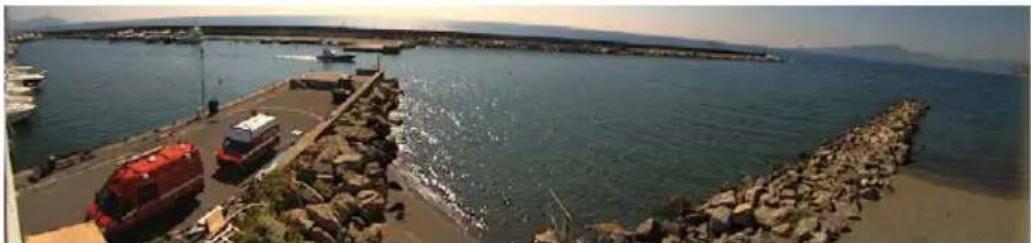
No MOBOTIX camera has ever had so many lens options! For the M25M, MOBOTIX offers seven lenses ranging from the 7° tele to the 180° Fisheye lens.

natural_image
Interior view of a hotel lobby with carpeted flooring, doors, and ceiling-mounted doors (no visible text or signage)MOBOTIX original image of 180° panorama (L12 lens)
MOBOTIX original image of 82° Super Wide-Angle
MOBOTIX original image of 180° panorama (L12 lens)
In combination with the hemispheric L12 lens (180° horizontal angle of view), the M25M becomes a Hemispheric camera.

natural_image
Interior view of a modern office lobby with two men standing in the foreground and reception desk (no visible text or signage)The M25M-Sec-CSVario is an M25M model that is shipped with a CS mount and a compact L27-60 1/2" Vario lens. To protect the lens against the weather, this version comes with a longer lens cover and threads for an external filter. This cover will work for lenses, which have a maximum diameter of 36 ~mm and which are not longer than 43 ~mm . Because of the image sensor's size of 1/2.5" , you can only use CS and C mount lenses (C mount lenses with adapter ring) for 1/2.5" sensors or larger. In comparison with MOBOTIX fixed lenses, Vario lenses are less robust and less reliable in the long run. For this reason, Vario lenses are typically used in applications where recording conditions change frequently, e.g., for surveillance of different construction sites.
The software of an M25M equipped with an L23 or L25 lens allows correcting the distorted image
MOBOTIX original image (L160 tele)
MOBOTIX Standard Lenses Are Easily Exchanged
Note that you can change all lenses of the M25M yourself on site whenever necessary (except the hemispheric L12 lens). The ordered lens is factory-aligned and quality-tested in the camera, which makes on-site camera focusing unnecessary in most cases. Each M25M is available for delivery with a lens of your choosing or no lens at all.
© MOBOTIX AG • Security-Vision-Systems • Made in Germany
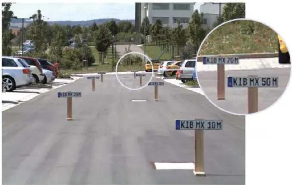
The image area captured by the camera varies depending on the selected lens (see Section 1.3, «Technical Specifications»). With a Super Wide Angle lens (e.g., L25 with 82°), for example, almost an entire room can be recorded from one corner. An L160 Tele lens enables an M25M with a high-resolution 5 megapixel sensor to clearly record a license plate number, for example, from a distance of approximately 75 meters.
Or even the serial number of a bill from a distance of 2 m/6 ft.

MOBOTIX original image (L160 tele)
Quick and easy navigation with a USB joystick
Virtual PTZ (vPTZ) - Without Motor

natural_image
Close-up of a red and black industrial control knob on a black base (no text or symbols visible)The M25M can also zoom in on details. This vPTZ function (virtual Pan, Tilt, Zoom) is a standard feature in the integrated M25M camera software. The image from the hemispheric camera can be enlarged using, for example, the mouse wheel, a joystick or a software-controlled PTZ panel and you can "move" the view to any section of the image. This provides the features of a mechanical PTZ camera without the disadvantages of maintenance and ear.

Depending on the platform used to operate the camera (Internet browser, MxEasy, MxControlCenter), the vPTZ function may work in a different manner. When using MxEasy or MxControlCenter, for example, specific software tools and an optional joystick make virtually zooming, panning and tilting much more comfortable. Even if you are using only an Internet Explorer (with activated ActiveX plug-in), you can use an optionally attached joystick.
© MOBOTIX AG • Security-Vision-Systems • Made in Germany
Simultaneous Corrected Live Image and Full Image Recording
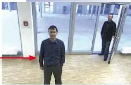
All conventional, motorized PTZ cameras only store the image that is currently viewed as the live image (live image recording). This has one serious disadvantage as the recording can only show what has happened in the "visible" portion of the image; the rest is lost and cannot be examined later on. For this reason, MOBOTIX has added the new full image recording feature to the M25M. This will not store the currently viewed image that reflects the pan/tilt position and the zoom setting chosen by the user, but the full sensor image, without vPTZ settings or image correction. When examining the recorded images, the vPTZ features again come into play, as they allow zooming the visible image and using the pan/tilt features to examine every corner of the recorded full image.
Example: The persons highlighted by the red circles in the center image would not have been recorded by a regular PTZ camera; the full image recording of the M25M in this example allows determining the exact time at which these persons had entered the image area recorded by the camera. A browser (Internet Explorer with MxPEG ActiveX plug-in), MxControlCenter or the new, multi-platform application MxEasy can be used to examine the recorded sequences.
Integrated vPTZ functions allow the complete stored full image to be analyzed at a later point in time (in MxEasy and MxControlCenter)

Live Image Stored Full In
Плс !шаде

natural_image
Interior view of a modern hallway with people walking, highlighted by red circles (no visible text or symbols)age Analysis in Full Image
ayomil luq betot2
natural_image
Two men standing in a modern building lobby with large glass doors and red directional arrows (no visible text or symbols)MicroSD card already integrated in the camera (M25M-Secure)
Internal DVR
The M25M-Secure features direct recording to the integrated MicroSD card, which makes the camera fully independent of any external storage media, even for longer periods of time. The camera internally stores high-resolution video, without requiring an external recording device or PC and therefore without overloading the network whatsoever. Old recordings can be overwritten automatically or automatically deleted after a specified period of time. When using a 16 GB SD card, for example, the camera can store more than a quarter million event images in VGA format (640x480). For security reasons, the camera can even encrypt the stored data.

Power failures are not an issue, since the video and image sequences remain safely stored on the SD card. Access to stored video sequences is possible at any time from the camera user interface in the browser, MxControlCenter or MxEasy. If you would like to archive sequences, you can export the required data to a PC or USB stick for evidence purposes, for example.
MxActivitySensor Video Motion Analysis: Secure Detection, Avoiding False Alarms
Regardless if there are large objects in the foreground or small objects in the background – MxActivitySensor will only trigger video recording and alarm messaging if something important is happening. Interference such as trees shaking in the wind, moving shadows and clouds and snow falling will no longer lead to false alarms. Since all of this is filtered automatically, all that remains is to set the direction of movement of objects that should trigger alarms.
Notes
1.2 M25M with Special Lens Hemispheric L12
Equipped with the 180° L12 lens, an entire room can be ideally monitored using only one M25M, which replaces the time-consuming and expensive installation of several standard cameras. The overview image provided by a single M25M, which may be personalized in a number of ways according to specific user requirements, not only reduces the number of required cameras, but also minimizes the system costs by reducing the wiring complexity, emergency power requirements and number of recording devices required.
L12 Lens: High-Resolution 180° Panorama
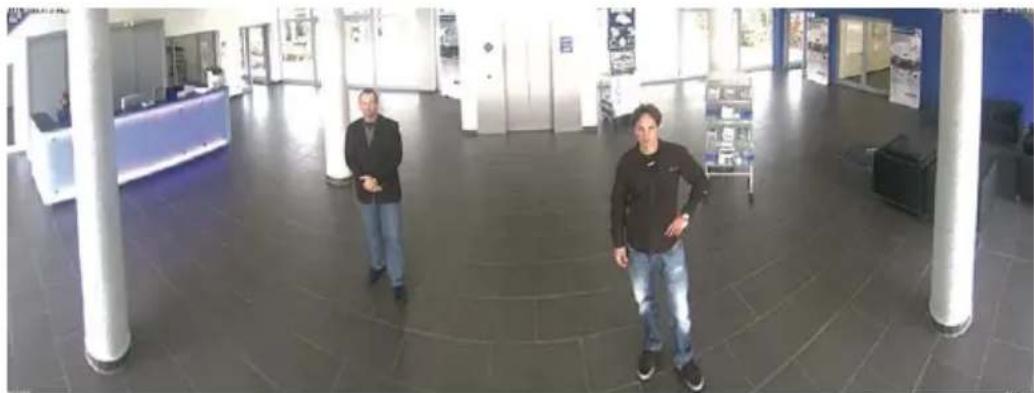
When several cameras are monitoring a single room, it is difficult to understand the room layout due to the different viewing directions of each individual camera. This makes it hard to comprehend the overall setting. The new panorama function of the M25M with the L12 lens delivers a widescreen, corrected image of a high-resolution 180^ allround view. High image quality is achieved through the use of a five-megapixel color sensor and the new hemispheric lens of the M25M.
With approximately 0.6 megapixels (1280x480 pixels), an M25M panorama image only requires a fraction of the original data volume or bandwidth of a 5MP full image (2048x1536 pixels).

Corrected image after panorama correction
Economical bandwidth usage due to smaller, camera-corrected images (no loss of image information)
The factory default setting of an M25M with an L12 lens is a high-resolution 180° panorama image, in which parts of the protective cover are still visible in the upper right and left corners of the image.
natural_image
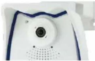
Close-up of a white electronic device with a circular lens and blue outline (no visible text or symbols)
natural_image
Interior view of a modern office lobby with two people standing in the aisle (no visible text or signage)Optimizing the M25M Panorama Image
In order to hide the protective cover in the panorama image, all that is often required is the "panorama correction" function, which has already been integrated into the camera software (controlling the camera via a web browser). Tilted vertical lines (if the camera is mounted at an angle) may be optically straightened to the image edges using this function (see Section 3.5). A welcome side effect of this is that the protective cover disappears from the image.
natural_image
Interior view of a modern office lobby with two men standing in the foreground (no visible text or signage)If this measure does not work in some special cases (camera tilt of approximately 0°), the protective cover can be removed from the image by zooming and, if necessary, by using the purely software-based downward panning function. The displayed image section or the panorama, as the case may be, is reduced slightly but the image details are enlarged as a result of zooming.

© MOBOTIX AG • Security-Vision-Systems • Made in Germany
Original full image

natural_image
Interior view through a circular lens showing people walking around a central building (no visible text or symbols)180° panorama image after the panorama correction function has been applied
Section 3.5 provides more details and information on how the panorama and horizon correction works (correct distortion in the image and position horizontally)
22/136
M25M Camera Manual: Product Overview
MOBOTIX original image Panorama/Focus
Original full image
MOBOTIX original image Double Panorama
natural_image
Circular interior view with red arrows pointing to interior scenes, no visible text or symbolsOriginal full image
L12 Lens: Panorama Focus – One Camera, Three Views
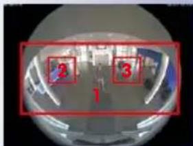
Maximum room overview while simultaneously viewing detail in a single image: the M25M is capable of providing two more views simultaneously with the 180° panorama, allowing you to focus on two scenes in parallel ("Panorama Focus" display mode).

natural_image
Three-panel photo sequence showing a man standing in a modern office lobby, with numbered annotations indicating steps (1, 2, 3) — no readable text or symbols present.L12 Lens: Double Panorama for a Simultaneous View in Two Directions
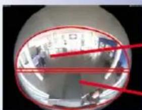
The "Double Panorama" display mode provides a panorama image of both halves of the area captured by the full image. Using the vPTZ functions, the panorama images can be changed as desired. The example here shows an overview panorama of the entire room, as well as the entrance, which would have otherwise no longer been visible in the panorama – a superb overview for the user.

natural_image
Two-panel image showing a man standing in a modern office space and another person in a dimly lit room with visible furniture and signage (no readable text or symbols)© MOBOTIX AG • Security-Vision-Systems • Made in Germany
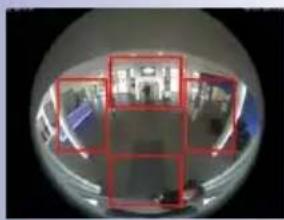
L12 Lens: Surround View (Quad View)
The "Surround" display mode of the M25M replaces four cameras all at once and simultaneously delivers four different directions "at a glance." If the camera is installed in the ceiling and is looking straight down, all four cardinal directions can be displayed, for example.

Each of the four views features a software-controlled pan/tilt/zoom function (virtual PTZ), allowing it to be customized as necessary. In order to facilitate camera operation, the M25M can store, in addition to the preset standard views, a total of 256 user-defined camera views using the vPTZ function, which can easily be brought up using joystick keys or softbuttons. Besides being able to manually move the virtual camera to specific positions and zoom settings, the camera can also "move" automatically. It does so by moving through the standard views or by showing the first 16 saved camera views (one after the other like in a slide show).


Original image M25M: Each of the four views can be modified individually
natural_image
Fisheye lens view showing a room interior with red bounding boxes and furniture (no visible text or symbols)Original full image
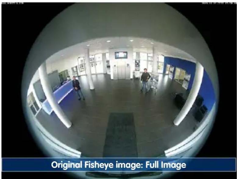
MOBOTIX original image - full image
MOBOTIX original image - Corrected and zoomed full image
L12 Lens: Full Image and Normal View
In addition to Panorama, Double Panorama, Panorama Focus and Surround views, the M25M image can be displayed on a monitor as the original Fisheye version ("Full Image" display mode) or as the camera-corrected image section ("Normal" display mode). Switching to one of the other display modes described is possible at any time within seconds.

L12 Lens: Factory Settings of the Standard Views for a Wall Installation
In order to fully exploit the potential of the M25M in the desired view, it may be necessary to adjust the factory settings using the integrated vPTZ function. We have summarized the factory default settings of a wall-mounted M25M with an L12 lens (with a downward tilt of approx. 15^ , 2.7 m high) here in order to give you a good idea of what to expect once the camera has been installed.

© MOBOTIX AG • Security-Vision-Systems • Made in Germany
Full image (left) and "Panorama" display mode (right)
Full image (left) and "Double Panorama" display mode (right)
Full image (left) and "Panorama/Focus" display mode (right)
Full image (left) and "Surround" display mode (right)
1.2.1 Advantages and New Features
The high-resolution M25M Allround is a universally deployable, highly innovative and easily concealable camera system. A powerful successor to the M24M, the M25M features a five-megapixel image sensor and is clearly superior to its predecessor in terms of image quality and frame rate.
Smooth HiRes Video Streams
The modified hardware of the M25M transmits the camera's video streams even more smoothly than the high-performance M24M, even when high resolution is required. Since image streams of 16 frames per second and higher are perceived as smooth video by the human eye, the maximum frame rate is limited to 30 frames per second (when using MEGA resolution of 1280x960) in order to provide sufficient camera processing power for other tasks.
Conclusive Still Images
Thanks to the proprietary MxPEG video codec developed exclusively for MOBOTIX cameras, the cameras offer the advantage that a recording can be paused at any given point and still provide meaningful and useful snapshots due to the absence of distortion. This is essential for security applications and allows individuals or license plates to be identified, for example. In contrast, the H.264 standard, which was developed for feature movies and is favored by some video security providers, cannot achieve this with the required level of quality.
Good Color Images Even in Low Light
The more light-sensitive an image sensor is, the better the image quality, especially when the ambient light level is low, such as at dusk and in heavy rainfall. The M25M offers the best MOBOTIX image quality that is currently available thanks to the light sensitivity provided by the five-megapixel color sensor that is four times higher than that of the previously used three-megapixel color sensor and the new MxLEO exposure control.
More Details When Zooming
The maximum zoom factor of the M25M is 1.26 times higher than that of the M24M due to the use of five-megapixel technology. This means that the degree of detail provided by the camera has improved by 26 percent. As a result, a M25M can now be installed even further away than before from the objects and areas to be monitored. In addition, this offsets the slightly smaller horizontal angles of view of the new five-megapixel sensors as compared to the M25M.
Black&White Image Sensor with 5 Megapixels
You can now order the M25M with a five-megapixel night sensor that can deliver black and white images with up to 5MP resolution. This results in larger images than those delivered by the previous 1.3-megapixel sensor with a perceptibly higher degree of details.
IT Cameras: Maximum Image Size Is Now HD Instead of VGA
The M25M-IT now generates HD images (1280x720 pixels) instead of the VGA images of predecessor models (640x480 pixels). The special quality advantage of a MOBOTIX IT camera with HD resolution (1280x720): The HD images of a MOBOTIX are generated by the high-resolution image sensor with 2592x1944 pixels and are optimized and scaled down for the HD format. Because of the high-resolution sensor, the generated images – especially with respect to quality and light sensitivity – are noticeably superior than regular HD cameras that are only using a simple HD sensor with 1280x720 pixels.
MxActivitySensor
The M25M provides an activity-controlled image analysis sensor as standard for detecting the movements of people and objects in a defined surveillance area (full image or section). The MxActivitySensor delivers reliable results particularly in outdoor area applications, in contrast to video motion detection that continues to be available and that registers all image changes in defined video motion windows. In the monitored area, the camera distinguishes between the continuous movements of vehicles, persons or objects that trigger an alarm and movements that do not set off an alarm such as shadows, changing light conditions and trees swaying in the wind.
Low Power Consumption in Accordance with PoE Standard (IEEE 802.3af)
A M25M does not use more power than its predecessor (typically 4.5 watts), despite the new sensor technology. Adjusting the PoE class via the camera software also enables the use of PoE switches that cannot be operated on all ports with PoE class 3 (up to max. 12.95 V).

natural_image
Close-up of a white and blue digital camera with a circular lens and perforated grille (no text or symbols visible)1.2.2 Decentralized Video System
Usually, cameras only supply images, while processing and recording take place later on a central PC using video management software. This centralized structure has too many limitations for high-resolution video systems since it requires high network bandwidth and the PC processing power is insufficient when using several high-resolution cameras. Due to the large number of computers and servers required, traditional centralized systems are therefore becoming less suitable and cost effective.
As part of the decentralized MOBOTIX concept, every camera features a high-speed processor, and, if necessary, digital long-term flash memory (MicroSD card) can be integrated to provide several days of recording time. The computer or video control center is required only to view and control the cameras, not to evaluate and

flowchart
graph LR
    A["CMOS\n5 Megapixels"] --> B["CPU\nImage Analysis"]
    B --> C["MicroSD\nRecording\n6.4GB"]
record video. This means that you do not have to rely on expensive, overloaded video management software as most of the important functions that require a large amount of processing power are integrated into the MOBOTIX cameras themselves.
Thanks to its integrated sensors, MOBOTIX cameras such as the M25M automatically detect when an event has occurred. If necessary, the cameras will respond immediately with an alarm sound and will establish a direct video and sound connection to a control room.
The M25M is equipped with a shock detector as standard (for all IT and Secure models). For example, if the camera receives a blow to the housing, it can simultaneously take a video of the offender, trigger a sound alarm and notify the security company by a SIP call. Due to the build quality and absence of moving parts, MOBOTIX cameras are extremely tough. This typically allows them to stay fully operational especially when they are subject to strong vibrations.
All MOBOTIX cameras are backlight-proof and are not adversely affected by the glare from direct sunlight. They deliver meaningful, detailed images at all times as the camera software supports easy programming of independent exposure windows, making them ideal for rooms with large glass fronts.
In the event of an alarm, MOBOTIX M25M cameras can also record lip-synchronous audio. The cameras therefore play an important role in analyzing and clarifying a situation. Thanks to an integrated speaker and microphone, each individual camera can also be used for bidirectional communication (two-way video communication), so you can easily use the MOBOTIX App with your iPhone or iPad on the road.
The decentralized MOBOTIX video solutions are superior to traditional systems in all major aspects. They are also considerably cheaper to operate since they require
- Fewer cameras due to the more accurate detail of panorama images with megapixel technology
- Fewer recording devices because in the decentralized system, ten times the standard number of cameras can be used to record high-resolution HDTV video with sound on one computer/server simultaneously
- Lower network bandwidth because everything is processed in the camera itself and the high-resolution images therefore do not have to be constantly transported for analysis
MOBOTIX System
Decentralized and Safe
Recording Software

natural_image
Computer case with red X mark and CD inside, no visible text or symbolsStorage on Computer

1.2.3 Green IP Video
The modern, network-based video security technology offers numerous advantages to use energy efficiently. Due to the special product and system properties, the decision to install MOBOTIX video systems is also a decision for Green IP Video: low power consumption and environmental friendly because of long life expectancy and minimal amount of materials involved.
Low Power Consumption
MOBOTIX cameras are cost-efficiently supplied via PoE. This reduces the expenses for power and, in addition, saves copper and other important raw material as less power cabling is necessary.
Robust
MOBOTIX IP66 cameras are highly robust and work – without high-power climate control and extra protective housing – in a temperature range from -30 to +50 °C/-22 to +122 °F.
Modern
Integrated into the cameras are high-power processors and flash storage, thus making energy-consuming servers and storage devices unnecessary. And, of course, the disposal of waste later.
High Resolution
A hemispheric MOBOTIX camera with two image sensors replaces up to eight standard cameras – including their consumption of energy and resources.
Sustainable
Without mechanical components, MOBOTIX cameras are maintenance-free and stay fully functional, even after years – and are, thus, more sustainable compared to other systems.
Forward-Looking
Even previous camera models can be easily updated and then offer new functionalities. Remote updates via Internet and the fact that the cameras are maintenance-free reduce trips by car, and, thereby, the negative effect on the environment.
Notes

natural_image
Close-up of a white electronic device with a blue-lit panel and central lens (no visible text or symbols)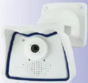
natural_image
White medical device with blue outline and central lens, mounted on a white plate (no visible text or symbols)
natural_image
Close-up of a white rectangular device with a central lens and blue border (no visible text or symbols)1.3 Technical Specifications
1.3.1 Lens Options
MOBOTIX offers the M25M with lenses in three different classes of focal length. Since MOBOTIX cameras are backlight-proof, none of these lenses requires a mechanical auto iris, thus making the camera extremely robust and maintenance-free. MOBOTIX lenses deliver good image quality even when using maximum digital zoom.
M25M with Standard Lenses and M14 Thread
A total of seven different MOBOTIX lenses are offered:
• L23 Super Wide-Angle with 92° angle of view (horizontally)
• L25 Super Wide-Angle with 82° angle of view (horizontally)
• L38 Wide-Angle with 55° angle of view (horizontally)
• L51 Wide-Angle with 40^ angle of view (horizontally)
• L76 Tele with 27° angle of view (horizontally)
• L160 Tele with 13° angle of view (horizontally)
• L320 Tele with 7° angle of view (horizontally)
The standard lenses can be exchanged at any time without having to dismantle the camera. The camera is shipped either with a color day sensor or a light-sensitive black and white sensor for low lighting conditions (Day or Night variants).
M25M with Hemispheric Lens L12 (Fisheye)
The hemispheric M25M model (M25M-Sec-D12) is only shipped with one L12 Fisheye lens with a horizontal angle of view of 180^ and 5 megapixel color sensor. The lens distortion that is specific to each lens is corrected in the live image by the MOBOTIX camera software. Due to the special outdoor-optimized design of the camera, the full sensor image cannot be used with all available image display options (parts of the weatherproof housing may be visible in the image). This model only allows using L12 lenses; other lenses cannot be used with this variant.
M25M with CSVario Lens
The M25M-Sec-CSVario is shipped with a CS mount, a compact L27-60 1/2" Vario lens (58° to 28° horiz. angle of view) and an optional color or black and white sensor (Day/Night). In addition, commercial CS and C mount lenses (C mount lenses with adapter ring) with a diameter of up 36 mm and a length of up to 43 mm that are designed for megapixel image sensors (1/2.5" and larger) can be used. Using other lenses will produce shadows at the image borders and will reduce image sharpness.
| Lenses with 5MP Image Sensor | L12 L23 | L25 L38 L51 | L76 L160 L320 | |||||
| Original image (image format 4:3) | 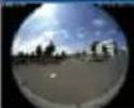 |  |  |  |  |  |  | |
| 35 mm equiv. 12 mm | 23 mm | 25 mm | 38 mm | 51 mm | 76 mm | 160 mm | 320 mm | |
| True focal length | 1.8 mm | 3.6 mm | 4 mm | 6 mm | 8 mm | 12 mm | 25 mm | 50 mm |
| Aperture | 2.0 | 1.8 | 1.8 | 1.8 | 1.8 | 1.8 | 1.8 | 2.5 |
| Horizontal angle of view | 180° | 92° | 82° | 55° | 40° | 27° | 13° | 7° |
| Vertical angle of view | 160° | 68° | 61° | 41° | 30° | 20° | 10° | 5° |
| At 1 m distance | ||||||||
| Image width | ∞ | 2.1 | 1.7 | 1.0 | 0.7 | 0.5 | 0.2 | 0.1 |
| Image height | 11.3 | 1.3 | 1.2 | 0.7 | 0.5 | 0.4 | 0.2 | 0.1 |
| At 5 m distance | ||||||||
| Image width | ∞ | 10.4 | 8.7 | 5.2 | 3.6 | 2.4 | 1.1 | 0.6 |
| Image height | 56.7 | 6.7 | 5.9 | 3.7 | 2.7 | 1.8 | 0.9 | 0.4 |
| At 10 m distance | ||||||||
| Image width | ∞ | 20.7 | 17.4 | 10.3 | 7.2 | 4.9 | 2.3 | 1.1 |
| Image height | 113.4 | 13.5 | 11.9 | 7.5 | 5.4 | 3.6 | 1.7 | 0.9 |
| At 20 m distance | ||||||||
| Image width | ∞ | 41.4 | 34.7 | 20.6 | 14.5 | 9.7 | 4.6 | 2.3 |
| Image height | 226.9 | 27.0 | 23.7 | 14.9 | 10.8 | 7.2 | 3.4 | 1.7 |
| At 50 m distance | ||||||||
| Image width | ∞ | 103.6 | 86.8 | 51.5 | 36.2 | 24.3 | 11.4 | 5.7 |
| Image height | 567.1 | 67.5 | 59.3 | 37.3 | 27.0 | 18.0 | 8.6 | 4.3 |
Notes
The specified focal lengths of the MOBOTIX lenses do not reflect the actual focal length of the lenses, but the focal length (Lxx mm) converted to 35 mm camera format. For example, the MOBOTIX L25 Super Wide-Angle lens has an actual focal length of 4 mm. This would be the equivalent of 25 mm on a 35 mm camera. It is therefore referred to as an L25. Since the image sensors in digital cameras have different sizes, converting the focal lengths to 35 mm camera as a known format allows the image formats and the fields of vision of the different lenses to be calculated and compared more easily. Another benefit is that you can easily set a 35 mm camera (analog or digital) to the same focal length as the MOBOTIX lens (Lxx) to obtain the same field of vision. This approach greatly facilitates lens selection.
The focal lengths of MOBOTIX camera lenses refer to standard 35 mm cameras
1.3.2 Camera Variants – Lenses, Hardware, Image Formats
| Camera Model |  |  |
| M25M-IT M25M-SEC | ||
| Lenses, Sensors | ||
| L12 Hemispheric - • | ||
| L23 Super-Wide-Angle • • | ||
| L25 Super-Wide-Angle • • | ||
| L38 Wide-Angle • • | ||
| L51 Wide-Angle • • | ||
| L76 Tele • • | ||
| L160 Tele • • | ||
| L320 Tele - • | ||
| CSVario L27-60 - • | ||
| Image sensor with individual exposure zones Color/BW Color/BW | ||
| Sensor sensitivity 5MP in lux at 1/60 s and 1 s | 0.25 / 0.013 (Color)0.05 / 0.0025 (BW) | 0.25 / 0.013 (Color)0.05 / 0.0025 (BW) |
| Hardware Features | ||
| IP protection class IP66 IP66 | ||
| Temp. Internal DVR (MB) | 32 | 64 |
| Internal DVR (MicroSD, SDXC, pre-installed) | • • | |
| Microphone/speaker •/• | •/• | |
| Passive infrared sensor (PIR) | -- | |
| Integrated temperature sensor | • • | |
| Shock detector | • • | |
| Power consumption in Watts (typical) | < 4,5 | < 4,5 |
| Variable PoE class | 2 - 3 | 2 - 3 |
| Image Formats, Frame Rates and Image Storage | ||
| Max. resolution (per sensor) | HD (1280x720) | 5MP (2592x1944) |
| Max. frame rate (MxPEG, max. resolution) | HD: 30 fps | 5MP: 10 fps |
| CIF images with 4 GB MicroSD DVR | 250,000 | 250,000 |
| VGA images with 4 GB MicroSD DVR | 125,000 | 125,000 |
| MEGA images with 4 GB MicroSD DVR | 40,000 | 40,000 |
| QXGA images with 4 GB MicroSD DVR | - | 20,000 |
1.3.3 Camera Variants – Software Features
| Camera Model |  |  |
| M25M-IT M25M-SEC | ||
| General Features | ||
| Digital zoom (continuous) with panning • • | ||
| Motion JPEG/MxPEG/H264 codecs •/•/• •/•/• | ||
| Programmable exposure ones • • | ||
| Snapshot rec. (pre-/post-alarm images) 10 50 | ||
| Terabyte ring buffer storage (internal/network) • • | ||
| Continuous rec. with sound (0.2 to 30 fps) • • | ||
| Event recording with sound • • | ||
| Time and event control | • • | |
| Weekly schedules/holidays | • • | |
| Web functionality (FTP, email) | • • | |
| Playback/Quad- und MultiView | • • | |
| Bidirectional sound in browser | • • | |
| Logo generator, animated | • • | |
| Flexible event logic | - • | |
| Master/Slave arming | - • | |
| Several scheduled privacy zones | - • | |
| Customized voice messages | • • | |
| VoIP telephony (audio/video, alert) • • | ||
| Remote alarm notification (network msg.) | • • | |
| Signal inputs/outputs, RS232 | Via MX-232-IO-Box | |
| Programming interface/HTTP API | • • | |
| Security features (HTTPS/SSL, IP-based access control, IEEE 802.1X network authentication) | • | • |
| Video Analysis | ||
| Video Motion detector | • • | |
| MxAnalytics | -- | |
| MxActivitySensor | - • | |
| Video Management Software | ||
| MxEasy, MxCC | • • | |
| MOBOTIX App | • • | |
1.3.4 Technical Data
| Technical Data M25M | |
| Model variants MX-M25M-Basic,MX-M25M-SEC, MX-M25M-SEC-Night | |
| Lens options 12 to 320 mm, 35 mm format, horizontal angle 180^ to 7^ | |
| Sensitivity Color sensor: 0.25 lux at 1/60 s, 0.013 lux at 1 sBlack and white sensor: 0.05 lux at 1/60 s,0.0025 lux at 1/1 sMxLEO - MOBOTIX Lowlight Exposure Optimization | |
| Image sensor 1/2.5" CMOS , 5 megapixels, progressive scan | |
| Max. image resolution Color/Black and white: 2592x1944 (5MP) | |
| Image formats | 2592x1944 (5MP), 2048x1536 (QXGA), 1920x1080 (full HD),1280x960 (MEGA), 1280x720 (HD), 1024x768, 800x600, 768x576(D1-PAL), 704x576 (TV-PAL), 640x480, 384x288, 320x240,160x120, custom formats |
| Max. frame rate M-JPEG (live/recording) | VGA: 30 fps, MEGA: 15 fps, QXGA: 8 fps, 5MP: 5 fps |
| Max. frame rate MxPEG (live and recording including sound) | VGA: 30 fps, MEGA: 30 fps, QXGA: 20 fps, 5MP: 10 fps |
| Image compression MxPEG, M-JPEG, JPEG, H.264 | |
| Internal DVR MicroSD card pre-installed (SDXC) | |
| External video ring buffer | Directly on NAS and computer/server without additional recording software |
| Software (included) MxEasy video management software,MxControlCenter control center software,MOBOTIX App for iOS devices with iOS 5.0 and higher | |
| Image processing | Backlight compensation, automatic white balance, image distortion correction, panorama correction, Video Motion detection, MxActivitySensor |
| Virtual PTZ Digital pan/tilt/zoom, continuous 8X zoom | |
| Alarm/events Video Motion detection, MxActivitySensor, external signal,temperature sensor, PIR, microphone, shock detector, notification over e-mail, FTP, IP telephony (VoIP, SIP), visual/acoustic alarms, pre- and post-alarm images | |
| Mikrophone and speaker Microphone and speaker integrated | |
| Audio features Lip-synchronous audio, two-way communication, audio recording | |
| Interfaces | 10/100 Ethernet, IPv4/IPv6, MiniUSB, MxBus; inputs/outputs and RS232 via accessories |
| Video telephony VoIP/SIP, two-way communication, remote controlling with key code, event notification | |
Functionality depends on camera variant (see Section 1.3.3, «Camera Variants - Software Features»)!
| Technical Data M25M | |
| Security User/group management | HTTPS/SSL, IP address filter, IEEE 802.1x, intrusion detection, digital image signature |
| Certifications EMC (EN 55022, CISPR 22, EN 55024, EN 61000-6-1/2, FCC part15B, CFR 47, AS/NZS 3548) | |
| Power supply Year-round Power | over-Ethernet (IEEE 802.3af); variable PoE class, approx. 4.5 W |
| Operating conditions IP66, -30 | to +50 °C/-22 to +122 °F |
| Dimensions/weight M25M | Wall mount: W x H x D: 140 x 189 x 222 mm/5.5 x 7.4 x 8.7 in; Weight: approx. 772 g/1.7 lb (including standard lens)Ceiling mount: W x H x D: 140 x 156 x 195 mm/ 5.5 x 6.1 x 7.7 in; Weight: approx. 715 g/1.6 lb (including standard lens) |
| Delivered parts Housing (high-resistance composite, PBT), white, conversion set for ceiling mount, mounting parts, Allen wrench, 50 cm patch cable, manual, software, MicroSD card (pre-installed) | |
natural_image
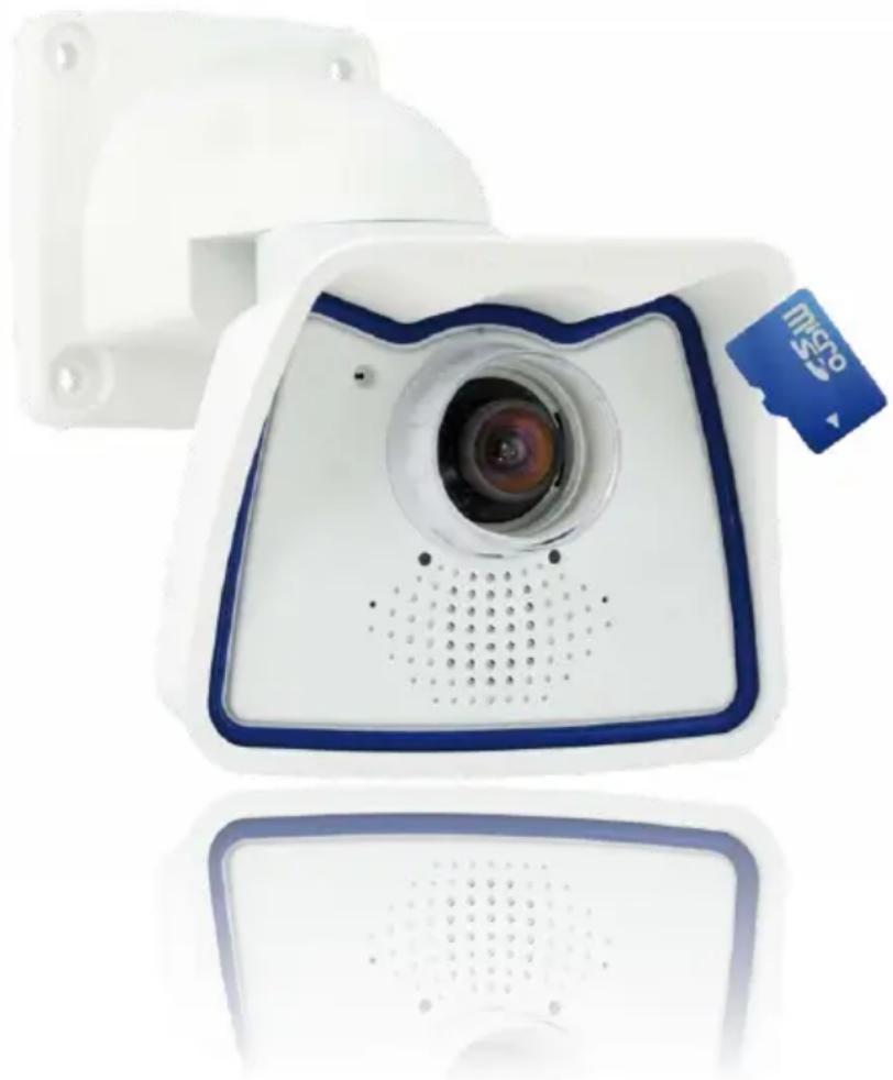
White camera with blue frame and lens, mounted on a wall-mounted bracket (no visible text or symbols)1.4 Delivered Parts and Dimensions
1.4.1 M25M Camera
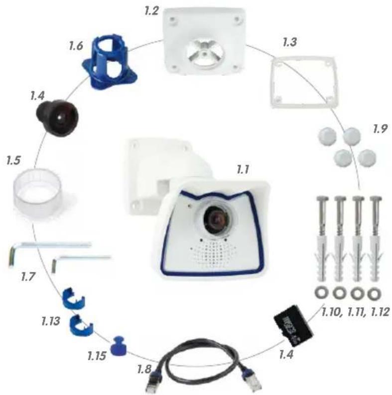
| Item Quantity Part Name | |
| 1.1 1 Camera in weatherproof housing including VarioFlex wall mount | |
| 1.2 1 Ceiling mount | |
| 1.3 1 Gasket for wall and ceiling mount | |
| 1.4 1 Lens, mounted (standard M14, CSVario, or L12) | |
| 1.5 2 | Lens cover, 1 mounted, 1 replacement (cover for CSVario/L12 not shown)* |
| 1.6 1 Lens wrench L12 (with M25M-Sec-D12/N12 only) | |
| 1.7 2 Allen wrench 5 mm, Allen wrench 2.5 mm | |
| 1.8 1 Special patch cable, 0.5 m, pre-installed | |
| 1.9 4 Caps for stainless steel wood screws | |
| 1.10 4 Stainless steel wood screws with hex head 6x50 mm | |
| 1.11 4 Stainless steel washers 6.4 mm | |
| 1.12 4 Screw anchors S8 | |
| 1.13 2 Cable retainer with bayonet catch (patch cable, Mini USB) | |
| 1.14 1 MicroSD card pre-installed (SDXC) | |
| 1.15 1 Lock plug Mini USB | |
Camera Housing and Connectors
The MOBOTIX M25M consists of the camera in the weatherproof housing and the VarioFlex mount.
Connectors
• Network (Ethernet network including PoE supply)
- Mini USB (e.g. for ExtIO)
- MxBus (for MOBOTIX expansion modules)
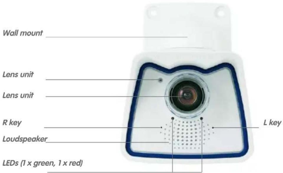
Make sure that the white ring remains in the lens cover as this ring reduces light reflections and prevents the camera LEDs from adding reflections to the images

natural_image
Close-up of a white cylindrical object with a red arrow pointing to a circular feature (no text or symbols visible)
Note
Note on fastening cables leading into the camera:
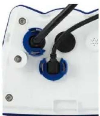
Cables passing in to the back of the camera (patch cable for the network connection and for Mini USB) are secured using a special cable retainer with bayonet catch.
When replacing this cable, ensure that the cable is properly seated in the port and that the retainer with the blue bayonet catch is locked (short clockwise turn until it clicks into place).
natural_image
Close-up of a white electronic device with blue and black connectors (no visible text or symbols)Removing the Cable Retainer
Rotate the bayonet catch anti-clockwise to the "open circle" symbol (see figure). The catch may be removed from the side. The cable can now be pulled out of the camera.
Open the cable retainer by rotating the bayonet catch to the marked position
Bayonet catch open


natural_image
Close-up of a white electronic device with blue and black components, showing wiring and mounting holes (no text or symbols visible)Caution
Only use original MOBOTIX cable to connect the camera. Standard cables purchased from other suppliers do not meet the necessary specifications for proper protection (no longer weatherproof according to IP66).

natural_image
Close-up of a black Ethernet cable with blue and silver connector (no text or symbols visible)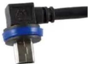
natural_image
Close-up of a black electrical connector with blue and gray bands (no visible text or symbols)MiniUSB cableEthernet patch cable
MOBOTIX patch cables are available as accessories in different lengths (1 m, 2 m, 5 m and 10 m)
Replacing the Cable Retainer
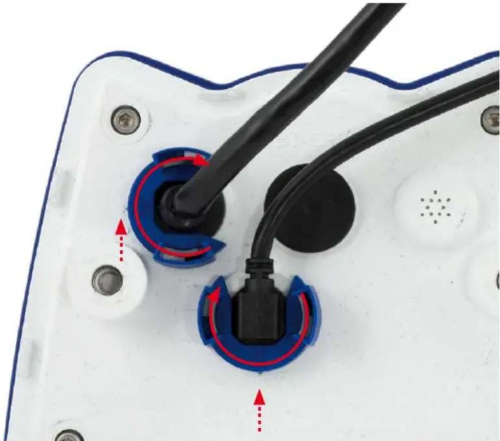
Insert the cable into the receptacle on the camera. Position the bayonet catch from the side (opening points to the right). Rotate the bayonet catch clockwise to the "filled circle" symbol (see figure). The cable is now properly retained.
natural_image
Close-up of a white electronic device with blue and black components, showing wiring and directional arrows (no text or symbols)Close the cable
retainer by rotating the bayonet catch to the marked position
Bayonet catch closed

1.4.2 Dimensions for Wall Installation

1.4.3 Dimensions for Ceiling Installation
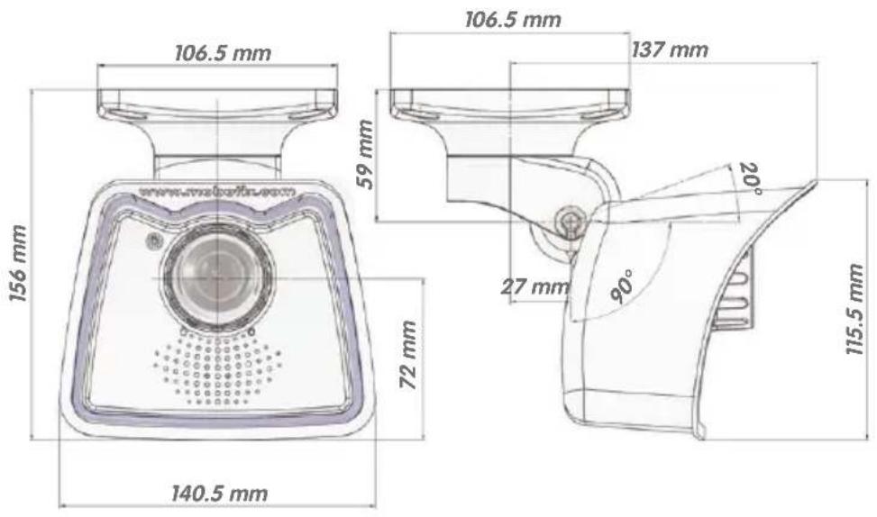
1.4.4 Dimensions of Wall Mount

1.4.5 Drilling Template Wall and Ceiling Mount
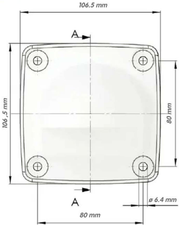
Note
Find the folded drilling template at the end of the manual.
Make sure that the drilling template is not scaled or adjusted to the paper size when printing the PDF file (enlarged or reduced).
© MOBOTIX AG • Security-Vision-Systems • Made in Germany
With the ceiling mount, the size of the contact surface is identical to the wall/ceiling and to the position of the drill holes
Find the drilling templates (scale 1:1) at the end of the manual as a fold-out
1.5 Available Accessories
1.5.1 Lens Cover with Glass Pane
Order no.: MX-M25M-OPT-LCSG
As an additional accessory, the M25M with standard lens (M14 thread) can be supplied with a protective cover that has a glass pane instead of one made of plastic. This will improve the durability of the lens cover when used in extremely rough conditions (at sea, in sand storms, etc.). This lens cover also has a thread size that fits external filters (40.5 mm x 0.5 mm) available from photo shops. For example, you could install a polarization filter to cancel out the reflections from windowpanes or windshields. Using this lens cover together with the L23/L25 Super Wide Angle lenses is not recommended, since this lens cover produces shadows at the image borders. The (longer) cover supplied with M25M models with the CSVario lens is equipped with the glass pane as standard.

MX-M25M-OPT-LCSG

natural_image
Close-up of a plain cylindrical object with a metallic rim (no text or symbols visible)MX-M25M-OPT-LCGL
1.5.2 Pole Mount
Order no.: MX-MH-SecureFlex-ESWS
If you are intending to mount the camera to a pole, you should consider using the MOBOTIX Pole Mount for M25M cameras. This mount is made of 3 mm powder-coated stainless steel (white) and has been designed specifically for outdoor use. The supplied stainless steel straps allow the mount to be attached to poles with diameters between 60 mm and 180 mm (2.4 in to 7.1 in). By design, the pole mount does not allow the use of a flush-mounted wall outlet.

natural_image
Three white electronic device components: a square sensor with a blue outline, a rectangular cover, and a vertical slot (no text or symbols visible)1.5.3 MiniUSB Cable to MiniUSB (Straight/Angled)
Order no.: MX-CBL-MU-EN-STR-05/2/5 (straight/angled)
The MOBOTIX MX-232-IO-Box can be connected directly to the M25M with this cable, which is up to five meters long.

natural_image
Coiled black cable with two connectors (no text or symbols visible)Only cables with angled plugs can be used for the M25M
1.5.4 MiniUSB Cable to MiniUSB (Angled/Angled)
Order no.: MX-CBL-MU-EN-EN-PG-05/2/5 (angled/angled)
The MOBOTIX ExtIO can be connected directly to the M25M with this cable, which is up to five meters long.

natural_image
Coiled black electrical cable with two connectors and a white connector (no text or symbols visible)1.5.5 MiniUSB Cable to USB-A Socket
Order no.: MX-CBL-MU-EN-AB-05/2/5
USB-based storage media (for example, USB hard drives) can be connected directly to the M25M with this cable, which is up to five meters long.

natural_image
Black USB cable with two connectors (no text or symbols visible)1.5.6 Ethernet Patch Cable for Bayonet Catch
Order no.: MX-OPT-CBL-LAN-1/2/5/10 (length: 1 m/2 m/5 m/10 m)
The MOBOTIX-developed special cable can be installed in a waterproof manner and has an integrated sealing gasket. Every M25M ships with a 0.5-m-long cable as standard, which can be exchanged for a patch cable up to 10 m in length.

natural_image
Coiled black cable with two USB connectors (no text or symbols visible)1.5.7 NPA-PoE-Set
Order no.: MX-NPA-PoE-EU and MX-NPA-PoE-INT (Version EU and Version INT) Order no.: MX-CBL-NPA-BAT-2 (battery cable for mobile voltage sources)
This is a multifunctional PoE injector according to the IEEE 802.3af standard – with three connectors (for network, camera/PoE device, PC), universal power supply unit with interchangeable adapter plugs and crossover function. The NPA-PoE-Set connects and remotely supplies a M25M with power via an Ethernet cable up to 100 m in length. The blue adapter can also be connected to mobile voltage sources from 12 to 57 V DC by means of an additionally available battery cable. The "EU" version of the NPA-PoE-Set is supplied as standard with a European adapter, while the "INT" version includes four adapters (EU, USA, UK, AUS).

natural_image
Blue camera and LED power adapter components with attached cables (no text or symbols visible)1.5.8 MX-Overvoltage-Protection-Box
Order no.: MX-Overvoltage-Protection-Box-RJ45
Order no.: MX-Overvoltage-Protection-Box-LSA
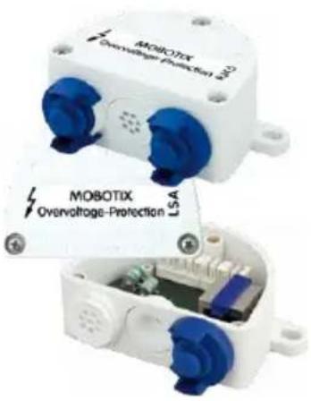
Weatherproof network connector (protection class IP65, -30 to +60 °C/-22 to +140 °F) with surge protection of up to 4 kV for MOBOTIX IP cameras, ideal for replacing the MX-Patch-Box.
At the same time, the MX-Overvoltage-Protection-Box provides a weatherproof connection of a camera's patch cable to a network patch cable (-RJ45 variant) or a network installation cable (-LSA variant).
1.5.9 MX-NPA-Box
Order no.: MX-OPT-NPA1-EXT
The MX-NPA-Box is a weatherproof PoE injector conforming to the IEEE 802.3af standard and is designed to connect external voltage sources (12 to 57 V DC) to a MOBOTIX camera.
The MX-NPA-Box is equipped with the Patch-Box's weatherproof and extremely compact exterior housing (protection class IP65, -30 to +60 °C/-22 to +140 °F), which means it can also be installed in the space of the Outdoor Wall Mount. Interfaces of the MX-NPA-Box: Camera via patch cable, Ethernet via LSA+ and external power supply via terminal connector (12 to 57 V DC possible).
1.5.10 MX-GPS-Box
Order no.: MX-OPT-GPS1-EXT
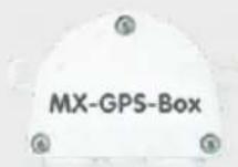
The MX-GPS-Box primarily serves as a high-precision time source for systems without an Internet connection. In addition, it can provide triggering based on GPS events (reaching or moving away from a specified position; exceeding or not reaching a specified speed). This interface box can be attached to all MOBOTIX cameras with an MxBus interface.

natural_image
Two views of an industrial control box with blue and green components, showing internal circuitry (no text or symbols visible)
natural_image
White GPS box device with mounting holes and a small protrusion (no visible text or symbols on body)The MX-GPS-Box is equipped with the same compact housing as the other interface boxes (protection class IP65, -30 to +60 °C/-22 to +140 °F). This interface box should not be installed inside of other wall mounts, but on the exterior of the building with a large section of open sky above it. This ensures the best possible reception from GPS satellites and thereby the highest possible accuracy of the received GPS data. The maximum length of the MxBus wiring (0.8 mm diameter wires) is 50 m/55 yd.
1.5.11 MX-232-IO-Box
Order no.: MX-OPT-RS1-EXT
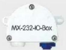
This box provides the signal inputs and outputs as well as the RS232 (serial) interface. It replaces the connections that were handled on the older camera models via a D-Sub 15-HD connector. The MX-232-IO-Box (protection class IP65, -30 to +60 °C/-22 to +140 °F) can be attached

natural_image
White industrial device labeled 'MX-232-IO-Box' with blue internal component (no readable text beyond label)to all MOBOTIX cameras with an MxBus or USB interface. The maximum length of the MxBus wiring (0.8 mm diameter wires) is 50 m/55 yd. If the MiniUSB connector is used, the maximum cable length is 5 m/16 ft.
1.5.12 ExtIO Expansion Module
Order no.: MX-ExtIO
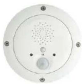
The device, which is suitable both for on-wall and in-wall installations, contains a powerful speaker, microphone, infrared motion sensor, ambient temperature sensor, two input and two output contacts and two illuminated keys. It is ideal for door communication, elevators, access control systems, etc. The ExtIO is suitable for use as direct connection to the S15 via a MiniUSB cable (max. 5 m), which can be ordered separately, or as a network connection via the PoE switch.
natural_image
Circular white electronic device with a perforated speaker and control knob (no text or symbols visible)1.5.13 Mx2wire+ Media Converter
Order no.: MX-2wirePlus-Set-PW
The Mx2wire+ system allows an Ethernet network with PoE to be set up via two-wire cables, which saves users from having to lay several hundred meters of Ethernet cable. For example, an existing two-wire cable of an analog video camera can be reused to connect a high-resolution and modern IP network camera. Mx2wire+ is delivered in the standard wall outlet frame in different designs; however, it can also be used with the available on-wall socket that is included.

natural_image
Close-up of a white electronic device with a circular vent and indicator lights (no visible text or symbols)1.5.14 Installing Interface Boxes Under a Varioflex Wall Mount
Signal input/output
RS232
GPS time and position information

Ext. power supply (e.g., solar)
Surge protection & network connector
If you are using the Varioflex wall mount, you can easily fit an interface box under the wall mount. You will find the corresponding drilling template at the end of this manual.
Note that the construction of the ceiling mount does not permit installing interface boxes underneath.

natural_image
Close-up of a white medical device with a blue circular component and triangular connectors (no visible text or symbols)1.5.15 Other Accessories
Since the range of accessories for the MOBOTIX system keeps growing, you should visit the MOBOTIX website www.mobotix.com in the Products > Accessories section to see the entire list of available accessories.
THE MOBOTIX INFORMATION CHANNELS
MOBOTIX
www.csc10.com
Support on the MOBOTIX Website
www.mobotix.com/other/Support


The MOBOTIX Video Tutorials
www.mobotix.com/other/Support/Tutorials


Seminars on MOBOTIX Campus
www.mobotix.com/other/Partners/Seminars


The MOBOTIX YouTube Channel
www.youtube.com/MOBOTIXAG

1.6 MOBOTIX Software
1.6.1 Integrated Camera Software (Firmware)
MOBOTIX cameras and connected MxBus modules operate with built-in firmware whose functions are accessed by the MOBOTIX MxControlCenter, MxEasy remote stations and MOBOTIX App.
The M25M models therefore also feature a variety of functions that are integrated in the firmware: from motion detection and long-term storage right through to alarm notification via video IP telephony. The virtual PTZ functions allow you to continuously zoom into or out of a MOBOTIX camera image using either the mouse wheel or a joystick.
When recording image or video sequences, you can choose to store either the section of the live image that is visible or the full sensor image (full image storage). This also allows you to examine parts of an image or video that had not been visible in the live image section on display at the time of the recording.
Unlike in the camera systems from other manufacturers, there is no need to buy an install additional software on your computer thanks to the MOBOTIX firmware that can be accessed directly in a web browser via the camera IP address. Instead of using a web browser, you can also download the free MxControlCenter or MxEasy video management software from the MOBOTIX website (www.mobotix.com > Support) to quickly display multiple cameras on one monitor or on an entire video wall, switch alarms with sound or conveniently search for an event. The MOBOTIX App for iOS devices (iPhone, iPad, iPad mini, iPod touch, iOS version 5.0 and higher) is also available free of charge from the App Store for your mobile applications.
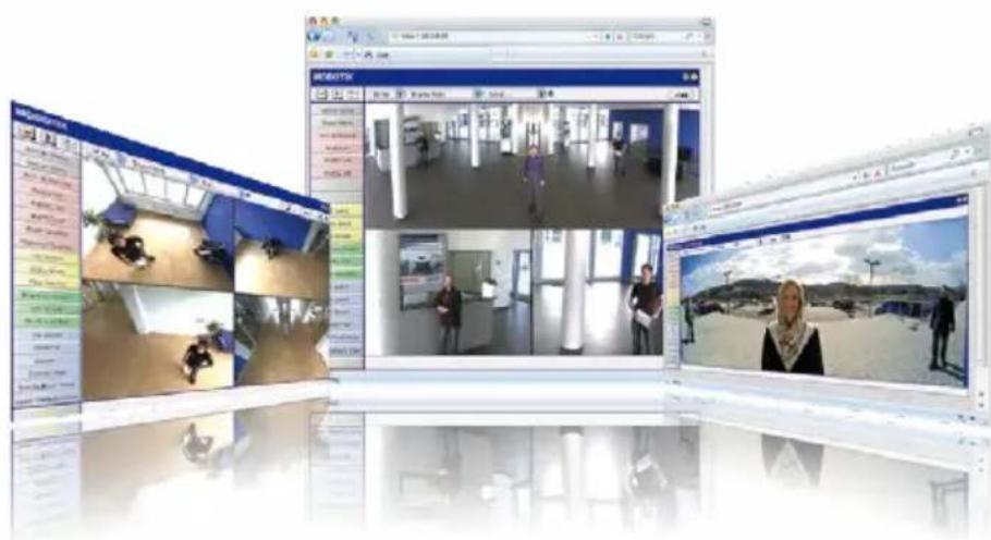
Download free of charge from www.mobotix.com
No license fees Free updates

Several hundred cameras can be managed on a standard computer
Download free of charge from www.mobotix.com
No license fees Free updates
1.6.2 MxControlCenter
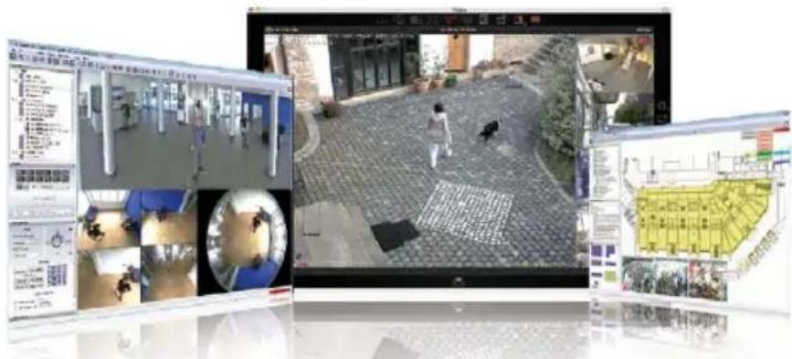
The MxControlCenter video management software can be used to combine any number of cameras at any locations into a well-structured and powerful video security system with centralized or local access-protected operation and analysis.
The state-of-the-art software, specifically tailored to support high-resolution MOBOTIX network cameras, provides a user-friendly user interface and camera image display, convenient video search functions, effective alarm handling, automatic camera integration, video storage on file servers as well as useful configuration and update wizards.
MxControlCenter – Professional Video Management
• Proven worldwide in the most demanding video applications thousands of times over
- Unlimited number of users and cameras
- No license fees
- Individual user interface, adaptable to each individual user
- Simplest installation and complete use on any standard PC
- Convenient layout editor for integrating real building plans
- Integration of conventional network and analog cameras as well
• For Microsoft Windows
1.6.3 MxEasy
MxEasy makes it simple to operate the most important functions of the camera thanks to its intuitive user interface and represents a new approach to viewing and controlling MOBOTIX cameras. The clear design allows you to manage up to 16 cameras, and the application can show up to four cameras at the same time.
All settings selected in MxEasy (for example, virtual camera position, zoom, brightness, volume, microphone sensitivity, image storage, signal outputs) can be used immediately and are stored instantly in the configuration of the corresponding camera. The calendar functions integrated in the Alarm Planner provide an innovative tool for the scheduled settings of one or more cameras. This tool not only controls video and sound recording based on certain time and date information, but also allows features like video motion detection, image brightness and the microphone to be activated/deactivated based on a date and time schedule.
MxEasy – Simple Operation of the Most Important Camera Functions
- Cameras can be installed without any knowledge of networks
• Supports up to 16 MOBOTIX cameras
• Time- or event-controlled recording - Time-controlled motion detection, image brightness and microphone
• For Microsoft Windows and Mac OS X


Suitable for up to 16 MOBOTIX cameras
Download free of charge from www.mobotix.com
No license fees Free updates
1.6.4 MOBOTIX App
Premium solution: There for you whenever and wherever you need it, the MOBOTIX App serves as the perfect remote mobile station that uses intelligent detailed solutions to increase security and convenience for users on a daily basis. The controls are optimized for use with touchscreen devices and feature three main views (Live, Player, Events), self-explanatory symbols, large software buttons, multifunctional sliders developed by MOBOTIX as well as simple gestures like swipe and tap, making it easy for newcomers and older users to work with professional security equipment. In addition, using mobile devices to operate the various functions such as door opening, activating the voice mailbox, switching the door bell off at night and switching a light on/off, creates added value in the form of greater convenience and security in every day life.
MOBOTIX App - Mobile Remote Station for MOBOTIX Cameras and Door Stations
- Bandwidth-optimized remote access via WLAN (WiFi) or the Internet
• Live images and recordings in the best MOBOTIX HiRes quality - Two-way communication, door opening and video mailbox access
- Doorbell and alarm notifications, protection of privacy
- Convenient search functions, playback of external MxPEG videos
- Grouping of cameras and filtering of events
• Free from the App Store for the iPad, iPad mini, iPhone and iPod touch
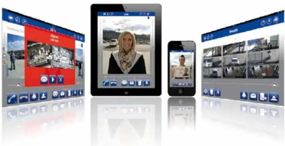
Notes
2 INSTALLATION
Although the MOBOTIX M25M has been primarily designed for installation on walls and ceilings, it can also be installed on a mounting pole using the appropriate MOBOTIX accessories. The different installation options are described in Section 2.2, «Mounting the Camera with Wall Mount» and the following sections, while the drilling templates are included at the end of the manual.
2.1 Preparing the Installation
Before mounting the MOBOTIX M25M, the following questions should be answered:
- Where will the camera be mounted?
- Which other mounting options are available?
- How is the camera connected to the network and how is the power supplied?
- How are the connections furnished from the building?
- What cabling considerations are necessary?
The following sections contain answers to each of these questions. If you have more detailed questions, please ask your MOBOTIX partner directly or contact the MOBOTIX support. To find the contact data, please open www.mobotix.com and the Support section.
2.1.1 Mounting Options: Wall, Ceiling, Pole
Like all MOBOTIX cameras, the M25M is extremely flexible in terms of how and where it can be installed. An M25M can be used for both indoor and outdoor applications. In fixed or mobile applications – constantly changing locations or in/on vehicles of any kind. The M25M cameras are weatherproof according to IP66 and can work reliably in temperatures ranging from -30 to +50 °C/-22 to +122 °F without extra housing, heating or fan. A practical sun protective cover is integrated into the extremely resistant housing, which is made of UV-resistant special-purpose plastic.
Thanks to the camera's unique VarioFlex mounting system (supplied as standard), the camera can be mounted quickly and easily on any wall, ceiling or even a round pole of up to 18 cm diameter (when combined with the stainless steel pole mount). The VarioFlex mounting system allows a wide positioning range in both the horizontal and vertical directions (rotating and tilting) to enable precise adjustment to suit the area to be monitored.
The wall mount also fits directly over flush-mounted RJ45 sockets (without the frame) and MOBOTIX interface boxes to fully conceal the cable, thus improving the security of the installation.
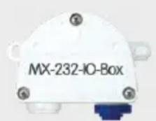
Signal input/output
RS232

GPS time and position information
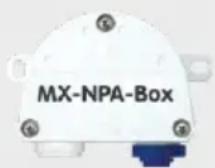
Ext. power supply (e.g., solar)

Surge protection & network connector

Mounting to a CeilingMounting
The VarioFlex mount consists of a central joint, which is directly screwed into place with the weatherproof M25M housing, and a wall and ceiling mount, which is fastened to the central joint with just one screw. In addition to being easy to install, the VarioFlex mount enjoys the advantage of a completely concealed cabling and high impermeability to water and dust (IP66). Wall and ceiling mounts are designed so that they can be mounted over conventional flush-mounted sockets (without the frame) or cavity sockets and conceal them completely. In addition, the wall mount easily covers a MOBOTIX interface box.
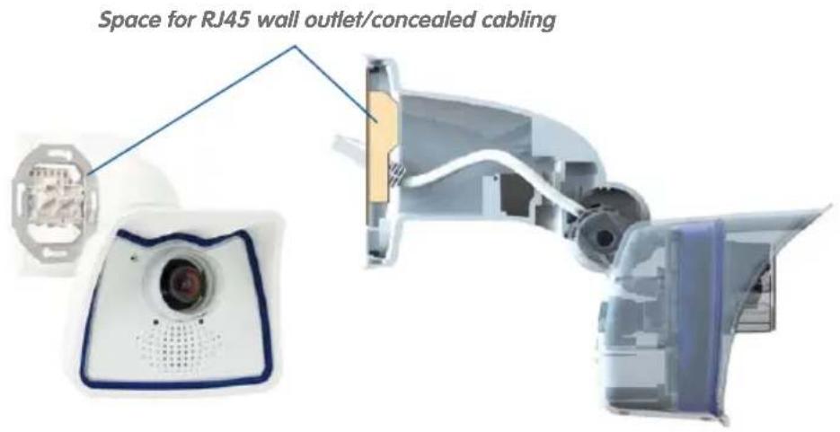
Before attempting to mount the camera to a wall or ceiling, make sure that you have found the best camera position. It is important that the camera's field of view is not obstructed in any way. Once the camera has been mounted to a wall or ceiling, you can fine-tune its position. If the monitored area changes from time to time or the camera has to be installed in a different location, the camera lens can be exchanged in just a few easy steps and used, without having to upgrade to new video software.
Turning/tilting mounted to wall
- horizontally: 180^
• vertically: -90^ to +20^
Turning/tilting mounted to ceiling
· horizontally: 360°
• vertically: -90^ to +20^
VarioFlex wall mount with concealed cabling, covering flush-mounted sockets and MOBOTIX Interface boxes
Wall-mounted
• horizontally: 180°
• vertically: -90^ to +20^
Ceiling-mounted
• horizontally: 360°
• vertically: -90^ to +20^
Mounting to a Wall
The M25M can be mounted to the wall of a building or structures, even mobile surfaces, for both indoor and outdoor use. The camera is mounted using the pre-installed VarioFlex mount (supplied as standard), which is easily secured using the four enclosed screws and screw anchors (depending on the surface, it can also be mounted without screw anchors directly over the flush-mounted socket). The Ethernet connection cable of the camera has already been guided through the mount and simply needs to be connected with the network cable (e.g., by using an MX-Overvoltage-Protection-Box). By adjusting the VarioFlex mount as required, the captured image area can be precisely adjusted to the desired practical application. The camera can be turned or tilted 180° horizontally and 110° vertically (from -90° to +20°).

Mounting to a Ceiling
By exchanging the wall mount for the separately supplied ceiling mount, the M25M is ready to be mounted to ceilings in just a few easy steps thanks to the VarioFlex system. This mounting option is of particular benefit when monitoring rectangular rooms with a single camera. In such cases, the Super Wide Angle lenses L23 and L25 allow the room to be monitored almost entirely by an M25M mounted to the ceiling in one of the corners. Using the software-driven PTZ, you can easily zoom in on image details in either the live image or the recording. The camera can be turned or tilted 360^ horizontally and 110^ vertically (from -90^ to +20^ ).
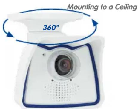
© MOBOTIX AG • Security-Vision-Systems • Made in Germany
Mounting the Camera with Pole Mount
Especially when using the camera in mobile outdoor scenarios (e.g., for surveillance of construction sites), the camera is often installed on round poles. In such cases, MOBOTIX recommends using the virtually indestructible pole mount (MX-MH-SecureFlex-ESWS) that is available as accessory for the M25M. This pole mount is made from white, powder-coated stainless steel and is used in combination with the pre-installed VarioFlex wall mount of the camera.
You can attach the mount to poles with diameters between 60 mm and 180 mm/2.4 in to 7.1 in. Best results are obtained when using high metal poles, since they allow running the network cabling inside, well-protected from tampering. For more detailed information on the installation process, see Section 2.2, «Mounting the Camera with Wall Mount» and the following sections, while the drilling templates are included at the end of the manual.
2.1.2 Mounting with Hemispheric Lens L12
The camera must be correctly positioned at the wall or ceiling in order to be able to use the high-resolution hemispheric image display option of the M25M with hemispherical L12 lens. The entire hemisphere of the room in front of the camera is then effectively monitored.
High-Resolution Panorama Images
The M25M with L12 lens is primarily suited to providing an excellent overview in the form of a high-resolution panorama image, and less suitable for more exact details. For active operation, the camera should be mounted at an (out of direct reach) height ranging from 2.50 m to 3.50 m. Facial recognition up to 1.50 m (5 ft) distance to the object is very good and up to 3 m (9.8 ft) is still sufficient. Objects can be recognized even at distances of 5 m and more from the camera. During installation, ensure that the camera is focused on the most important areas of the room as directly as possible, in order to optimize image quality and to provide the desired level of detail recognition. This applies above all to wall and ceiling installations that must be carried out at greater heights for technical or other reasons (over doors, windows, etc.). Only by tilting the camera appropriately can the lens capabilities be fully utilized.

natural_image
Close-up of a white square security camera with blue trim, mounted on a wall (no visible text or symbols)MOBOTIX recommendation

MOBOTIX original image of 180° panorama (L12 lens)
Captures an entire room


Allround View
Thanks to its hemispheric lens, a single M25M can monitor an entire room right including the four corners (360° Allround View). The camera's ideal position is on the ceiling in the center of the room. Rooms with a square floor area of up to approx. 40 m² (48 yd²) in general allow recognizing details even at the borders of the full image. If you would only like to know if persons enter a room or for monitoring specific objects, rooms with more than 100 m² (120 yd²) floor area can be monitored using a single camera.

natural_image
3D geometric diagram showing a cube with internal triangular planes and numbered regions (1, 2, 3), no text or symbols present.Image quality (precision) diminishes as the distance of an object to the camera focal point increases: 1 very good, 2 good, 3 satisfactory
© MOBOTIX AG • Security-Vision-Systems • Made in Germany
Furthermore, the "camera view from top to bottom" can also be achieved by mounting the camera to a wall or a pole at a tilt of 90^ .
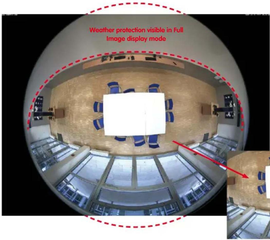
By panning/tilting/zooming the image, the concealed area can be completely removed from the image

natural_image
Top-down view of a meeting room with a large white table and blue chairs, no visible text or symbolsNote
Part of the captured image area (especially in full image display mode) is concealed behind the protective cover of the M25M housing. For this reason, M25M cameras with L12 lens should be adjusted so that the concealed areas are not those that are supposed to be monitored. By panning/tilting/zooming the image, the concealed area can be completely removed from the image.
When directly connecting to the computer, the PoE adapter replaces a cross-over cable
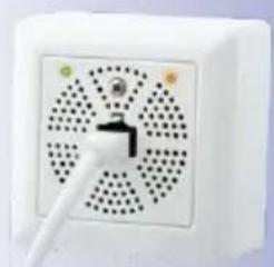
natural_image
Close-up of a white electronic device with a perforated panel and a black triangular button, no visible text or symbols.2.1.3 Network Connection and Power Supply, UPS
Power Over Ethernet (PoE Conforming to IEEE 802.3af)
All M25M models are supplied with power using the PoE standard. The Network Power Adapter (MX-NPA-PoE-Set) may be used for smaller installations. For larger installations, it is worth investing in a PoE capable supply device available on the market.

The maximum length of the network cable for power supply over an Ethernet cable is 100 m. The Mx2wire+ media converter set (available as an accessory) can be used to extend the range of an Ethernet connection up to 500 m in length (maximum transmission speed for a 500-m cable: 45 Mbps and 12 W for the PoE device).
Note
The MOBOTIX M25M can be powered by switches or routers which support the PoE (Power-over-Ethernet) standard and conform to IEEE 802.3af.
Advantages of PoE power supply:
- Allows setting up centralized backup power supply via the network.
- Reduces energy consumption.
- No extra network connection for camera required.
Using Uninterruptible Power Supplies (UPS)
You should install an uninterruptible power supply (UPS) in order to maintain a continuous power supply even when utility power fails. These devices also provide full protection against electrical surges and voltage fluctuations, enhancing the reliability of the system as a whole.
When using a more powerful 19" rack-mounted UPS, you can also protect all other network components (for example, switches, routers, PoE switches, etc.).
Since MOBOTIX cameras do not require any heating, even during winter, the average power consumption of less than 5 watts is very low. This, in turn, means that you can centralize the UPS-protected power supply by injecting power into the Ethernet cables (max. 100 m). This kind of protected power supply can be used either with MOBOTIX PoE products (MX-NPA-PoE + Universal Power Supply) or with PoE-compliant switches according to IEEE 802.3af.
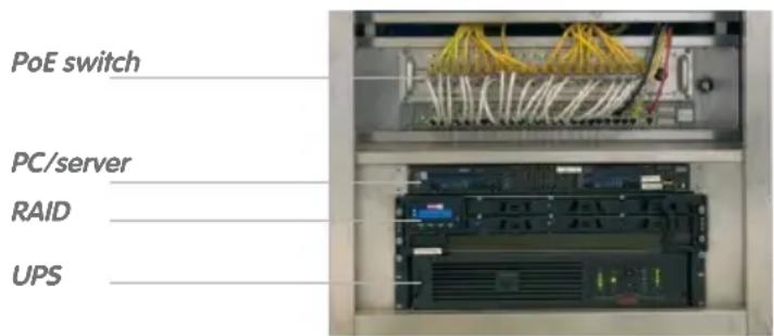
2.1.4 Preparing the Camera Connections, MX-Overvoltage-Protection-Box
Once the camera position, the position of the cable outlets and the method of power supply have been decided upon, the cabling can be installed. Before installing the MOBOTIX M25M, you should make sure that the network connections have been properly tested so that the proper functioning of the camera is guaranteed.
If the camera is to be installed outdoors, you should also install the MOBOTIX MX-Overvoltage-Protection-Box (optional accessory). This interface box not only provides overvoltage protection of up to 4 kV for MOBOTIX IP cameras, it also provides simple and weatherproof connection of the cameras to a network patch cable (-RJ45 variant) or a network installation cable (-LSA variant).
For additional information on the MX-Overvoltage-Protection-Box, open the Products > Accessories > Interface Boxes section on www.mobotix.com.
UPS units not only protect the camera against power failures, they also protect all other connected network devices against damage from voltage peaks and lows

2.1.5 Wiring, Fire Prevention, Lightning and Surge Protection
When installing the wiring inside or outside of buildings, make sure you always adhere to the relevant regulations on wiring, fire prevention and protection against lightning.
MOBOTIX cameras are protected against the effects of small electrical surges by a range of measures. These measures, however, cannot prevent the camera from being damaged when stronger electrical surges occur. Particular care should be taken when installing the camera outside to ensure proper protection against lightning, as this also protects the building and the entire network infrastructure.
MOBOTIX recommends having MOBOTIX cameras installed only by certified specialists accustomed to installing network devices and having proper respect for the applicable regulations regarding lightning protection and fire prevention as well as the current technology for preventing damages from electrical surges.
Guidelines for Wiring
- Data cable: Make sure you only use double-shielded CAT5 or higher cable (S/STP) for Ethernet connections.
- Outdoors: Installing the camera outdoors requires special precautions and measures regarding the cables as well as lightning and surge protection (see below).
- Wire lengths: The cable segments must not exceed the maximum allowed cable lengths in order to ensure proper data transfer (see Section 2.7).
- Avoiding induction: When running data cables parallel to existing regular power lines or high-voltage wires, make sure you observe the minimum distances to the power cables.
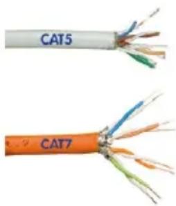
natural_image
Two types of colored wires labeled CAT5 and CAT7, showing exposed internal structures (no text beyond labels)Fire Prevention
When installing the power lines to the camera, make sure you always adhere to the country-specific regulations (e.g. VDE in Germany, IEEE in the USA) in effect on wiring and fire prevention at the site of the installation.
Lightning and Surge Protection
In order to avoid damage to MOBOTIX cameras from overvoltages, you should always install the MX-Overvoltage-Protection-Box. This competitively priced and weatherproof network connector provides reliable protection against overvoltages of up to 4 kV; the box is easily installed in the Outdoor Wall Mount, for example (see Section 1.5.8, «MX-Overvoltage-Protection-Box»).
More information is available at an institution such as the International Electrotechnical Commission (IEC, www.iec.ch) or at a manufacturer of protection devices against lightning and electrical surges, such as Dehn (www.dehn.de).

2.2 Mounting the Camera with Wall Mount

natural_image
Close-up of a white and blue digital camera with a lens and ventilation grille (no text or symbols visible)The M25M is a versatile camera designed for use in indoor and outdoor applications. The camera must always be installed with the VarioFlex mount, which has been prepared at the factory for wall mounting and allows the cabling to be concealed. The best camera position for the selected lens must be found before mounting the camera to the wall (see Section 2.1.1, «Mounting Options: Wall, Ceiling, Pole» and Section 2.1.2, «Mounting with Hemispheric Lens L12»). Once the camera has been mounted to the wall, you can fine-tune its position. Please read the notes on protecting the camera against condensation (see Section 3.6.1).
2.2.1 VarioFlex Wall Mount
Using the VarioFlex Wall Mount, the camera can be precisely panned, both horizontally and vertically, to suit the area that is to be monitored.
When mounted to a wall, the camera can be turned or tilted as follows:
• horizontally: 180°
- vertically: 110^

© MOBOTIX AG • Security-Vision-Systems • Made in Germany
See Section 3.6.1,
«Protecting the Camera
Against Condensation»
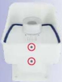
natural_image
Close-up of a white mechanical component with two red circular markers on its side (no text or symbols visible)Turning/tilting mounted to wall:
• horizontally: 180°
• vertically: 110°
64/136
M25M Camera Manual: Installation

natural_image
Close-up of a white electronic component with two blue ports, enclosed in a red circle (no text or symbols visible)MX-Overvoltage-Protection-Box in Wall Mount
In order to ensure a flush finish with the surface, connect the camera patch cable to the network cable using a standard adapter that is protected in the wall mount or install an MX-Overvoltage-Protection-Box, which is easily installed in the cavity of the VarioFlex wall mount. For additional information on the MX-Overvoltage-Protection-Box, open the Products > Accessories > Interface Boxes section on www.mobotix.com. Note that you can also install a flush-mounted socket with RJ45 connectors. In this case, make sure that the outlet lines up with the upper rim of the mount later on.

natural_image
Product photo of a smartwatch and a digital camera module (no visible text or symbols)Pliers to break out cable guides

natural_image
Close-up of black-handled pliers with red handles against a plain background (no text or symbols visible)
When installing on-wall cabling, breaking out one of the four possible openings in the base of the wall mount will ensure that the cables can be fed neatly into the camera. The connection to the camera patch cable can be established using a suitable adapter within the wall mount
Caution: If using the wall mount outdoors, only use the opening at the bottom to prevent water from entering the mount!
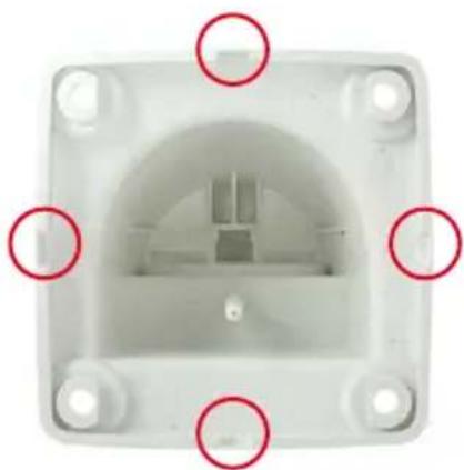
natural_image
Top-down view of a white plastic electrical socket with four mounting holes and red-circled features (no text or symbols)Procedure
- Install and prepare the network connection: The pre-installed camera patch cable must be connected with the on-site network cable. The connection can either be established using an installed flush-mounted socket with RJ45 connector or – in the case of a protruding network or patch cable – using the MX-Overvoltage-Protection-Box. In both cases, the connection is well protected and is neither accessible nor visible from the outside.
- Drill the holes: Use the supplied drilling template for the camera (found at the end of the manual). Drill the holes for the supplied screw anchors. Screw anchors do not have to be fitted if the surface is made of wood. To secure the mount, the supplied stainless steel hex head screws will later be screwed directly into the surface. In order to facilitate screwing in wood, the positions should first be predrilled using a 2 mm drill bit, for example (drilling depth just slightly less than screw length).
- Attach wall seal: Place the white rubber seal with the groove on the edge of the wall mount.
- Connect the cable: Connect the on-site network cable to the camera patch cable using an adapter or insert the patch cable into the RJ45 outlet. When using an MX-Overvoltage-Protection-Box, follow the installation instructions supplied with the product. You can download the PDF file from the MOBOTIX website www.mobotix.com in the Support > Manuals section. Make sure that the cables are not bent or squashed.

natural_image
White cylindrical device with attached black cable and gray connector (no visible text or symbols)

natural_image
White industrial pipe clamp device with mounting bracket (no visible text or symbols)
No screw anchors are required in wooden surfaces
Additional seal possible (e.g., heat shrink tube)


Screw caps for fastening screws
- Attach the camera: Place the wall mount over the drill holes and hold it against the wall. Then use the four screws each with a washer and tighten them using the appropriate wrench. Do not overtighten the screws as this may damage the plastic mount. Check that the screws are securely in place and place the white caps on the screw heads. Then position the camera as described in Section 3.2.
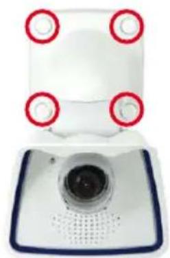
natural_image
Close-up of a white electronic device with four red circular indicators on top, mounted on a blue base (no visible text or symbols)- Clean the lens cover: Once you have removed the white protective foil fixed to the front of the lens cover, clean the cover that has already been screwed on with a clean soft cotton cloth for optimal image results. The cover does not have to be removed.

natural_image
Close-up of a white and blue digital camera with a red arrow pointing to its side, no visible text or symbols.- Establish a connection to the camera, check the
image: Establish a connection to the camera as described in Section 3.1, «Manual and Automatic Operation – Overview» and the following sections. The live image from the camera should be visible on the computer monitor. Check the image section on the computer monitor.
Note
Make sure that you always use the VarioFlex Mount with ceiling adapter when installing to ceilings (see Section 2.3, «Mounting the Camera with Ceiling Mount»).
2.3 Mounting the Camera with Ceiling Mount

natural_image
Close-up of a white and blue digital camera with a circular lens and perforated grille (no text or symbols visible)The M25M is an allround camera designed for use in indoor and outdoor applications. The camera is always installed together with the VarioFlex mount, which has been prepared at the factory for wall mounting and can be converted to a ceiling mount with just few single touches. The best camera position for the selected lens must be found before mounting the camera to a ceiling, or to an overhang or balcony (see Section 2.1.1, «Mounting Options: Wall, Ceiling, Pole» and Section 2.1.2, «Mounting with Hemispheric Lens L12»). Once the camera has been mounted to the wall, you can fine-tune its position. Please also read the notes on protecting the camera against condensation (see Section 3.6.1).
2.3.1 VarioFlex Ceiling Mount
Using the VarioFlex Ceiling Mount, the camera can be precisely panned, both horizontally and vertically, to suit the area that is to be monitored.
When mounted to a ceiling, the camera can be turned or tilted as follows:
• horizontally: 360°
- vertically: 110^


natural_image
White handheld phone with blue frame and 360° rotation indicator (no text or symbols on device)© MOBOTIX AG • Security-Vision-Systems • Made in Germany
68/136
M25M Camera Manual: Installation

natural_image
Close-up of a white RJ4 connector with black cable and red dotted arrows indicating direction (no text or symbols)Standard adapter for connecting cables
Additional sealing of wall mount with silicone recommended (at the wall sealing), if surface is not even
Pliers to break out cable guides
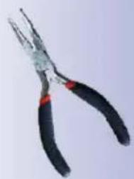
natural_image
Close-up of a pair of needle-like pliers with black handles and red end caps (no text or symbols visible)In addition, a cavity or flush-mounted socket can be installed for the network cable protruding from the ceiling, which allows sufficient space to connect the network cable with the camera patch cable using a standard adapter.
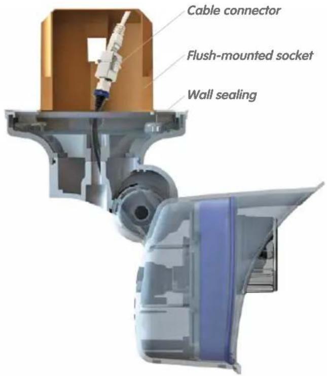
When installing on-wall cabling, breaking out one of the four provided openings in the base of the ceiling mount will ensure that the cables can be fed neatly into the camera. The camera patch cable must be connected to the network cable using a suitably sealed adapter.

natural_image
Top-down view of a white square mechanical component with a central hole and four mounting holes, marked by red circles (no text or symbols)© MOBOTIX AG • Security-Vision-Systems • Made in Germany
Procedure
- Convert to ceiling mount: Simply remove the lock screw on the central joint and exchange the wall mount for the supplied ceiling mount. Before fastening the ceiling mount to the central joint (using the screw of the wall mount), the patch cable is guided through one of the four openings.
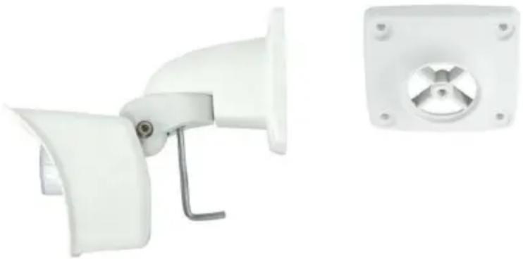
natural_image
White industrial fan or guard device with attached bracket and side panel (no text or symbols visible)-
Install and prepare the network connection: Guide the pre-installed camera patch cable through one of the four openings in the ceiling mount. This will be connected later with the network cable using a suitable adapter, for example, in a pre-installed cavity socket.
-
Drill the holes: Use the supplied drilling template for the camera (found at the end of the manual). Drill the holes for the supplied screw anchors. Screw anchors do not have to be fitted if the surface is made of wood. To secure the mount, the supplied stainless steel hex head screws will later be screwed directly into the surface. In order to facilitate screwing in wood, the positions should first be predrilled using a 2 mm drill bit, for example (drilling depth just slightly less than screw length).
-
Attach ceiling seal: Place the white rubber seal with the groove on the edge of the ceiling mount.
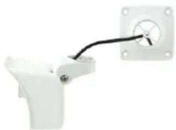
natural_image
White mechanical component with a black cable and mounting bracket (no text or symbols visible)
natural_image
Close-up of a white plastic electrical component with a black cable inserted, showing internal components and mounting holes (no text or symbols visible)No screw anchors are required in wooden surfaces

Screw caps for fastening screws
-
Connect the cable: Connect camera patch cable via connector. Make sure that the cable is not bent or squashed.
-
Attach the camera: Place the ceiling mount over the drill holes, use the four screws each with a washer and tighten them using the appropriate wrench. Do not overtighten the screws as this may damage the plastic mount. Check that the screws are securely in place and place the white caps on the screw heads. Then position the camera as described in Section 3.2.

natural_image
Close-up of a white dental implant with three metallic screws mounted on a curved base (no text or symbols visible)- Clean the lens cover: Once you have removed the white protective foil fixed to the front of the lens cover, clean the cover that has already been screwed on with a clean soft cotton cloth for optimal image results. The cover does not have to be removed.
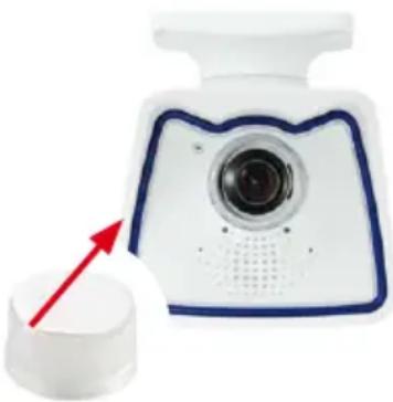
natural_image
Close-up of a white kitchen knife with blue trim and a circular head, showing a red arrow pointing to a lid (no text or symbols visible)- Establish a connection to the camera, check the image: Establish a connection to the camera as described in Section 3.1, «Manual and Automatic Operation – Overview» and the following sections. The live image from the camera should be visible on the computer monitor. Check the image section on the computer monitor.
Note
Make sure that you always use the VarioFlex mount with wall adapter when installing to walls (see Section 2.2, «Mounting the Camera with Wall Mount»).
2.4 Mounting the Camera with Pole Mount (Accessory)

natural_image
Close-up of a white digital camera with blue frame and lens, mounted on a metal wall (no text or symbols visible)If you are intending to mount the camera on a pole, you should consider using the MOBOTIX M25M Pole Mount. This mount is made of 3 mm powder-coated stainless steel (white) and has been designed specifically for outdoor use. The supplied stainless steel straps allow attaching the mount to poles with diameters between 60 and 180 mm (2.4 to 7.1 in). By design, the Pole Mount does not allow using a flush-mounted wall outlet. In order to ensure a weatherproof connection of the network devices, it is recommended to use an MX-Overvoltage-Protection-Box, which is easily installed in the cavity of the VarioFlex wall mount. For additional information on the MX-Overvoltage-Protection-Box, open the Products > Accessories > Interface Boxes on www.mobotix.com.
The camera is always installed together with the VarioFlex mount, which has been prepared at the factory for wall mounting and which is easily attached to the Pole Mount. The best camera position for the selected lens must be found before installing the camera (see Section 2.1, «Preparing the Installation»). Once the camera has been mounted to the pole, you can fine-tune its position.
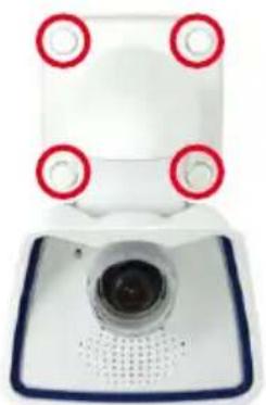
natural_image
Front view of a white handheld device with four red circular markers on top, mounted on a blue base (no visible text or symbols)Schwenkbarkeit bei
Mastmontage:
- horizontally: 180^
• vertically: 110°
2.4.1 Pole Mount (MX-MH-SecureFlex-ESWS)
Using the pre-installed VarioFlex Wall Mount, which is secured to the pole mount simply using four screws and nuts, the camera can be precisely panned, both horizontally and vertically, to suit the area that is to be monitored.
When mounted to a pole, the camera can be turned or tilted as follows, just like wall installation:
• horizontally: 180°
• vertically: 110°

Pole Mount Dimensions

Width: 140 mm/5.51 in Depth: 45 mm/1.77 in
Scope of Delivery and Required Parts
Please first check that all the components supplied with the Corner and Pole Mount Set are present in the original packaging.
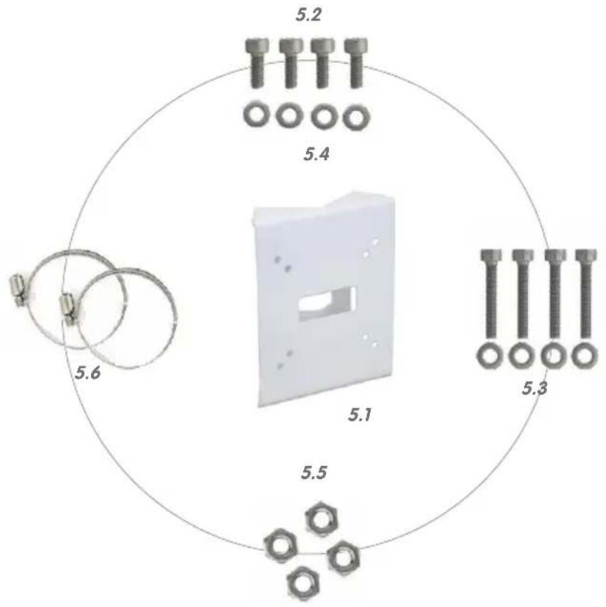
| Item Count Part Name | ||
| 5.1 1 | Pole Mount | |
| 5.2 4 | Stainless steel screws with hex head M6x20 mm | |
| 5.3 4 | Stainless steel screws with hex head M6x35 mm (not used) | |
| 5.4 8 | Stainless steel washers | |
| 5.5 4 | Stainless steel lock nuts M6 | |
| 5.6 2 | Stainless steel straps | |
In addition, you will need the screw caps for fastening screws supplied with the M25M (see Section 1.4, «Delivered Parts and Dimensions», item M.10).

Screw caps M.10
Procedure
- Prepare the cable: Guide the on-site network cable from behind through the middle opening of the pole mount. Ideally, the cable should be guided directly from the pole into the cavity socket of the VarioFlex Wall Mount, where it is connected with the camera patch cable via an adapter (e.g., the MX-Overvoltage-Protection-Box) to conceal the cabling.

natural_image
Simple diagram of a device with a black connector and white housing, no text or symbols present.- Prepare the straps: Guide the two stainless steel straps through the pole mount. The pole must have a diameter between 60 mm and 180 mm.

natural_image
Top-down view of a small mechanical component with metallic parts, placed on a plain white surface (no text or symbols visible)- Attach pole mount: Place the straps around the pole and tighten them using the screwdriver. If required, clip the ends of the stainless steel straps.

natural_image
Exterior view of a modern office building (no signage)- Apply rubber seal: Place the white rubber seal with the groove on the edge of the wall mount.

natural_image
Exterior view of a square enclosure with arched entrance and internal structure (no visible text or symbols)- Connect the cable: Connect the on-site network cable to the camera patch cable using an adapter or insert the patch cable into the RJ45 outlet. When using a MX-Overvoltage-Protection-Box, follow the installation instructions supplied with the product. You can download the PDF file from the MOBOTIX website www.mobotix.com in the Support > Manuals section. Make sure that the cables are not bent or squashed.
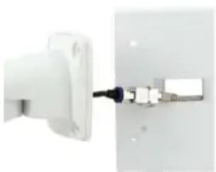
natural_image
Close-up of a white electrical outlet connector with a black cable inserted (no visible text or symbols)- Attach the camera: Place the wall mount over the predrilled positions in the pole mount and tighten it using the supplied M6x25 mm screws (item 2.2), washers (item 2.4) and M6 hex nuts (item 2.5). Place the white caps on the screw heads. Then position the camera as described in Section 3.2.
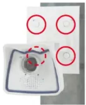
natural_image
Close-up of a white electronic device with four circular red-outlined features and a central circular component, no visible text or symbols.
Screw caps for fastening screws
- Clean the lens cover: Once you have removed the white protective foil fixed to the front of the lens cover, clean the cover that has already been screwed on with a clean soft cotton cloth for optimal image results. The cover does not have to be removed.

natural_image
Close-up of a white smart camera with blue trim and a red arrow pointing to the lens (no text or symbols visible)- Establish a connection to the camera, check the image: Establish a connection to the camera as described in Section 3.1, «Manual and Automatic Operation – Overview» and the following sections. The live image from the camera should be visible on the computer monitor. Check the image section on the computer monitor.
Note
Make sure that you always use the VarioFlex mount with wall adapter when installing to poles. Der VarioFlex Ceiling Mount is not to be used.
For more detailed information on the OnScreen Control, see Section 3.5

natural_image
Pure UI icons without any text, numbers, or symbolsHorizontal correction

Rotate image up to -30°
Rotate image up to +30°
2.5 Adjusting the Camera and Exchanging the Lens
2.5.1 Adjusting the Camera
-
Establish a connection to the camera as described in Section 3.2, «First Images and the Most Important Settings». The live image from the camera should be visible on the computer monitor.
-
Loosen the screws on the VarioFlex mount using the supplied Allen wrench so that you can easily turn and tilt the camera.
-
Display the desired camera section on the computer monitor, then turn and tilt the camera until you have found the best position and sharpness. Retighten the screws of the VarioFlex mount to prevent the position of the camera from changing.
-
If required, clean the lens cap's surfaces using a clean, lint-free cotton cloth.

natural_image
White plastic medical device with adjustable arm and handle (no text or symbols visible)2.5.2 Correcting the Image Horizon (for L12 Lens Only)
The M25M-Sec with hemispheric L12 lens allows the correction of an uneven image horizon via OnScreen Control that was possibly caused by the installation position. The image horizon can be adjusted by up to 30 degrees clockwise or counterclockwise and can be optically straightened by clicking on the corresponding icons (see image).
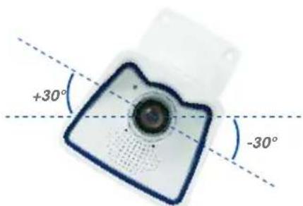
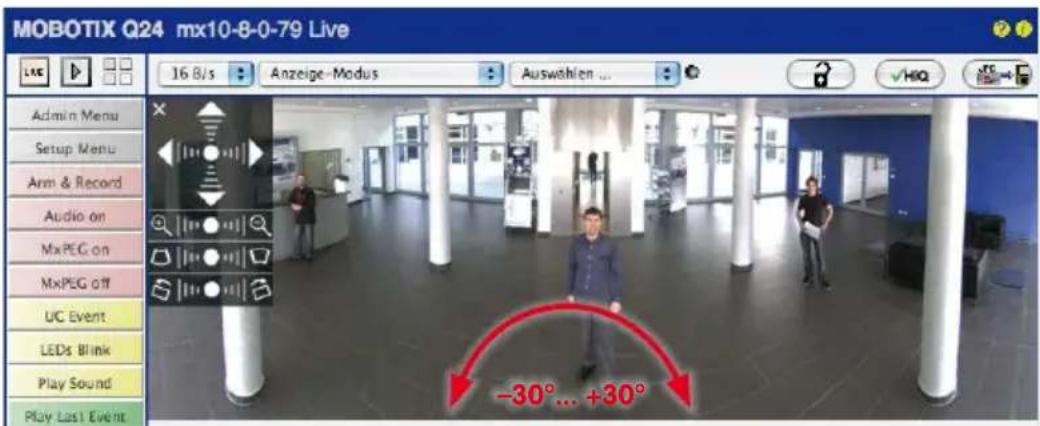
2.5.3 Exchanging the Lens
The M25M can be shipped from the factory with seven MOBOTIX standard lenses (L23, L25, L38, L51, L76, L160, L320) with the CSVario lens or the hemispheric L12 lens. This procedure applies equally for all lenses.
Only lenses with CS or C mounts may be used with the CSVario version of the M25M (Secure model only). MOBOTIX lenses with M14 thread cannot be used. Similarly, the standard versions of the M25M can only take the standard MOBOTIX lenses with M14 thread. The hemispheric L12 lens, C Mount and CS Mount lenses cannot be used. Upgrading to other model versions is not possible.
Proceed as follows to change a lens:

natural_image
Close-up of a camera lens mounted on a white electronic device with blue frame (no visible text or symbols)- Unmount the lens cover by turning it counter-clockwise.
- Remove the lens by turning it counter-clockwise.
- Screw the new lens (if present) back into the camera and restore the power supply of the camera.
- Adjust the image sharpness according to the camera's live image on the computer monitor. Make sure that you do not screw in the lens too far or by using excessive force, since doing so may damage the lens mount.
- Screw the lens cover onto the lens again and clean it, if required, using a clean, lint-free cotton cloth.
The focusing aid provides a visual aid when setting the image sharpness of a MOBOTIX camera lens (see Section 4.3.3, «Image and Audio Settings, Quick Controls» in the Software Manual).

natural_image
Close-up of a white electronic device with blue circular components and a central lens (no visible text or symbols)
natural_image
Close-up of a white appliance interior with a circular dial and red arrow pointing to a central component (no text or symbols visible)The white ring in the lens cover prevents the camera LEDs from adding light reflections to images
2.6 Replacing the MicroSD Card
The camera must be taken down to remove, insert or replace a MicroSD card. To avoid data loss, be sure to deactivate MicroSD card recording in the camera software and reboot the MOBOTIX camera before removing the card.
Caution
A MicroSD card may only be removed from the camera after you have deactivated. Recording to SD Card and rebooted the camera. Failing to do so may lead to loss of data! Make sure that the card is not write-protected!
2.6.1 Removing the MicroSD Card
- Deactivate recording: Recording to MicroSD card must be deactivated (Admin Menu > Storage on External File Server / Flash Device). If MicroSD card recording is still active, deactivate recording and reboot the camera. Section 3.4, «MicroSD Card Recording» contains more information on this topic.

natural_image
White electronic device with a black cable and indicator lights, no visible text or symbols- Remove camera from the weatherproof housing: Remove the two lock screws from the weatherproof housing and then remove the camera from the housing. In doing so, do not pull too hard on the lens cover. If required, use the long side of the 5 mm Allen wrench to carefully push the camera out of the housing from behind through the screw holes.

natural_image
White and blue mechanical device with a vertical arm and mounting bracket (no visible text or symbols)- Remove the connection cables: The connected cables (patch cable, MiniUSB) must be removed from the camera first by rotating and opening the bayonet catch (MxBus see Section 2.7.6).
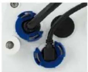
natural_image
Close-up of two blue and black plastic electrical connectors with screws (no text or symbols visible)- Remove the back of the camera and take out the MicroSD card: Remove the four screws from the back plate using the supplied 2.5 mm Allen wrench and carefully lift off the back plate. Gently push on the MicroSD card in the card slot of the camera. The card is released from the slot and can be removed from the camera.

natural_image
Close-up of a white plastic electronic component with black holes and red alignment markers (no text or symbols visible)To use the camera without a MicroSD card, continue by mounting the back plate (see step 2 in Section 2.6.2).
© MOBOTIX AG • Security-Vision-Systems • Made in Germany
2.6.2 Inserting the MicroSD Card
- Insert the MicroSD card: Push the MicroSD card into the card slot as shown, until an audible and perceptible click indicates it is in place.
- Mount the back plate: Replace the back plate of the camera housing, ensuring that the back plate screw holes are correctly positioned above the thread inserts.
- Screw the back plate tight and replace the connection cables: Place the four Allen screws back into the back plate and tighten the screws using the supplied 2.5 mm Allen wrench. The previously removed cables must now be reconnected (see Section 2.7.5 and Section 2.7.6).
- Attach the camera: Re-attach the camera to the weather-proof housing using the two lock screws. Make sure that none of the cables are bent or squashed.
- Activate recording: If you have inserted a MicroSD card that has already been MxFFS formatted, you can activate recording under Admin Menu > Storage on External File Server / Flash Device. Once the camera has been rebooted, it automatically activates recording.
- If you have inserted a new MicroSD card, it must first be formatted as described in Section 3.4, «MicroSD Card Recording».


natural_image
White plastic electronic component with black circular ports and red mounting holes (no text or symbols visible)
natural_image
Close-up of blue and black plastic components with connectors (no visible text or symbols)
natural_image
White electrical switch with black cable and terminal ports (no visible text or symbols)Push-push operation: insert the MicroSD card and push it in gently
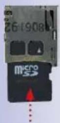
Bayonet catch closed

2.7 Network and Power Connection
2.7.1 Notes on Cable Lengths and Power Supply
- Power is supplied to the camera via the camera Ethernet connection (patch or installation cable). We recommend using a MOBOTIX PoE adapter or another similar high-quality PoE product to loop-in the power supply:
- One camera: with the PoE adapter (MX-NPA-PoE or MX-NPA-Box)
-
Multiple cameras: with PoE products conforming to IEEE 802.3af (PoE switch)
-
The maximum length of the network cable for power supply over an Ethernet cable is 100 m.
- Make sure that you only use switches or routers that support the 10/100 Mbps network interface of the camera.
- We highly recommend using uninterruptible power supplies (UPS) to provide backup power.
- If you are using IEEE 802.3af or IEEE 802.3at (PoE+) Power-over-Ethernet network components to supply power to MOBOTIX cameras, make sure, if possible, that these components do not have a fan. Since the power consumption of MOBOTIX cameras is very low compared to other products, the reliability of the entire system is increased, thus extending the life of these components.
Caution
Appliances with a maximum total power consumption of four watts may be connected to the MxBus connector and USB connector if power is supplied to the camera using PoE class 3. If PoE Class 2 is used, the power consumption of all the connected appliances should not exceed one watt!
For information on changing the PoE class, see Section 2.7.8, «Variable PoE».
2.7.2 Network Cabling For M25M With Patch Cables
Using a patch cable and an MX-Overvoltage-Protection-Box or MX-NPA-Box offers the following advantages:
- Quick installation/deinstallation
- No shortening of cable even when installing/deinstalling several times
- Hose-proof/dust-proof connection in accordance with IP66
- Additional protection against overvoltages of up to 4 kV when using the MX-Overvoltage-Protection-Box.
© MOBOTIX AG • Security-Vision-Systems • Made in Germany
Connection of additional devices with more than 1 W (via MxBus/USB): Max. ambient temperature +50°C/+122°F!
Connecting the Patch Cable to an MX-Overvoltage-Protection-Box, an MX-NPA-Box or a Standard Network Outlet
To establish the network connection of the camera using an MX-Overvoltage-Protection-Box or an MX-NPA-Box, remove the blue bayonet catch and the blue sealing plug from the right-hand side of the box. Insert the MOBOTIX patch cable into the box and fasten the cable using the blue bayonet catch.
For additional, information on how to install an MX-Overvoltage-Protection-Box or an MX-NPA-Box, open the Products > Accessories > Interface Boxes section on www.mobotix.com.
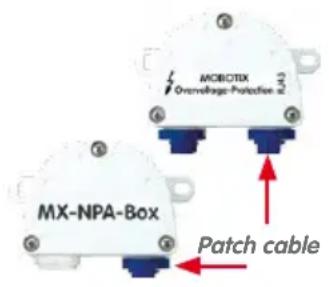
When using a standard network outlet (only for indoor installations), insert the MOBOTIX patch cable of the M25M directly into the network outlet.
If additional cables are required inside the housing, they must be connected as described in Section 2.7.6, «Connecting a USB Cable» and Section 2.7.7, «Connecting a Two-Wire MxBus Cable».
2.7.3 Power Supply Using a Switch
- Connect the factory pre-installed cable of the camera to the camera connector of the PoE adapter.
- Connect the LAN/Power connector of the PoE adapter to the Ethernet connector of the switch/router or the Ethernet port.
- Plug the RJ45 connector of the power supply unit into the PC/Power connector of the PoE adapter.
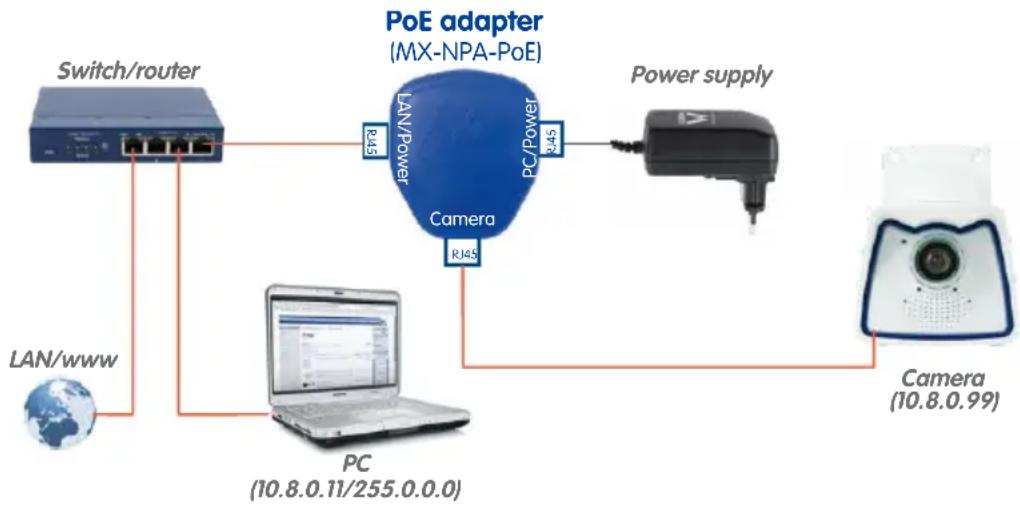
flowchart
graph TD
    A["Switch/router"] -->|LAN/WW| B["Laptop PC (10.8.0.11/255.0.0.0)"]
    B --> C["Camera (10.8.0.99)"]
    C --> D["Power supply"]
    D --> E["PoE adapter (MX-NPA-PoE)"]
    E --> F["PC/Power 345"]
    F --> G["Switch/router"]
IP addresses in the figure are shown only as an example
For the M25M you should use the blue MX-NPA-PoE-Set or the MX-NPA-Box - previous MOBOTIX network power accessories, such as the NPA-Set, Power-Box and Power-Rack (MX-NPA-Set, MX-NPR-4 and MX-NPR8/20) are not suitable for use with the M25M

82/136
M25M Camera Manual: Installation
IP addresses in the figure are shown only as an example
The PoE adapter replaces the crossover cable when directly connecting to a computer
For the M25M you should use the blue MX-NPA-PoE-Set or the MX-NPA-Box - previous MOBOTIX network power accessories, such as the NPA-Set, Power-Box and Power-Rack (MX-NPA-Set, MX-NPR-4 and MX-NPR8/20) are not suitable for use with the M25M!


IP addresses in the figure are shown only as an example
2.7.4 Power Supply When Connected Directly to a Computer
- Connect the factory pre-installed cable of the camera to the camera connector of the PoE adapter.
- Connect the PC/Power connector of the PoE adapter to the Ethernet port of the computer.
- Plug the RJ45 connector of the power supply unit into the LAN/Power connector of the PoE adapter.

flowchart
graph TD
    A["Power supply"] --> B["PoE adapter (MX-NPA-PoE)"]
    B --> C["PC (10.8.0.11/255.0.0.0)"]
    B --> D["Camera (10.8.0.99)"]
    B --> E["Camera"]
    B --> F["PG"]
    B --> G["RJ45"]
    B --> H["RJ45"]
2.7.5 Power Supply with Power-Over-Ethernet Products
Connect the factory pre-installed cable of the camera to a PoE port of the PoE switch/router. The switch/router must support the PoE standards IEEE 802.3af or IEEE 802.3at.

flowchart
graph TD
    A["LAN/www"] --> B["PoE/PoE+ switch/router"]
    B --> C["PC (10.8.0.11/255.0.0.0)"]
    B --> D["Camera (10.8.0.99)"]
© MOBOTIX AG • Security-Vision-Systems • Made in Germany
2.7.6 Connecting a USB Cable
Using the USB plug (red circle in figure), you can attach existing expansion modules, such as the MOBOTIX ExtIO (USB), the MX-232-IO-Box or external USB hard drives to the camera in a weatherproof and well-protected manner.
Procedure
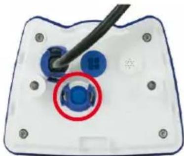
natural_image
Close-up of a device's internal components with a blue connector and black cable (no text or symbols visible)-
In case the camera had already been installed, remove the camera so you can access the connectors on the back.
-
Remove bayonet catch and USB plug: Turn the bayonet catch to the left (red arrow in figure), take it off and remove the blue USB plug.
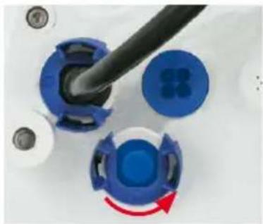
natural_image
Close-up of a blue and white mechanical component with a black tool inserted, showing a circular component with a red arrow indicating rotation (no text or symbols visible)- Insert USB plug: Push the MOBOTIX cable with the angled MiniUSB plug into the connector (red circle in figure).

natural_image
Close-up of a blue plastic component with a black plug and a red circle highlighting a black plug, no visible text or symbols.- Attach bayonet catch: Again attach bayonet catch and turn it clockwise until it gently snaps shut (see figure).

natural_image
Close-up of blue plastic mechanical components with a black cylindrical rod and red arrow indicator (no text or symbols visible)Only use USB cables with angled plugs for connecting USB cables to the M25M!

natural_image
Three black USB cable connectors with connectors and connectors, shown against a plain background (no text or symbols visible)The length of the entire MxBus wiring must not exceed 50 m/55 yd.

natural_image
Blue circular object with three internal holes, resembling a stylized button or knob (no text or symbols)Single-wire plug
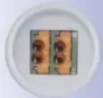
natural_image
Close-up of two rectangular objects with rounded tops on a white plate (no visible text or symbols)MxBus connector
2.7.7 Connecting a Two-Wire MxBus Cable
You can use such a cable to connect additional MOBOTIX modules (e.g., the MX-GPS-Box or the MX-232-IO-Box) to the M25M.
Note that you can attach two MxBus cables (each having two wires) to the MxBus connector (red circle in figure). Take care not to switch the polarity of the wires. It is recommended to use the same wire color for +/- for the entire MxBus system (e.g., red = +, blue = -).

natural_image
Close-up of a device's internal components with a red circle highlighting a blue component (no text or symbols visible)Procedure
-
In case the camera had already been installed, remove the camera so you can access the connectors on the back.
-
Prepare MxBus cable Remove the blue single wire plug. Strip 5 mm (1/5 in) of insulation from the wire ends of the MxBus cable, then push each wire into one of the four holes in the single wire plug (this prevents humidity from entering the camera).
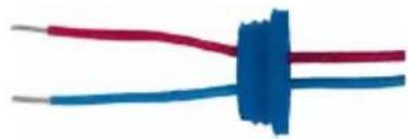
natural_image
Close-up of two wires with red and blue colors, no text or symbols visible- Connect MxBus cable: Push back the blue single wire plug so that you can easily attach the MxBus cable. Attach the MxBus wires by firmly pushing the wires into the corresponding connectors.
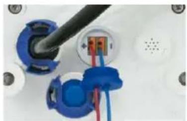
natural_image
Close-up of a blue electrical plug socket connected to a black cable, with red and blue wires visible (no text or symbols)If you need to remove one of the wires, unlock the connector by pressing on the orange-colored area using a small screwdriver, then pull out the wire.

natural_image
Close-up of a blue screwdriver inserted into a wall socket with a red and orange component (no text or symbols visible)- Close the MxBus connector. Carefully press the single wire plug into the connector socket and twist the MxBus wire pairs.

natural_image
Close-up of a white electronic device with blue and black components, no visible text or symbols2.7.8 Variable PoE
The power consumption of the camera depends on the functions in use as well as any peripheral devices connected (see table). PoE classes 1, 2 or 3 may be selected in the browser-based user interface in order to optimally adjust the camera to your system design (PoE switch in use, emergency power concept, etc.).
PoE Power Level Classes (IEEE 802.3af Standard)
| Class Max. power consumption Camera operating mode and peripheral devices | ||
| 1 | 0.44 W–3.84 W | LowPower mode; no peripheral devices (available soon) |
| 2 | 3.84 W–6.49 W | Normal mode; max. 1 W for MxBus peripheral devices |
| 3 | 6.49 W–12.95 W | FullPower mode; max. 2.5 W for MxBus peripheral devices (for example, MX-GPS-Box and MX-232-IO-Box to MxBus), max. 4 W for peripheral devices to MxBus and USB interface |
Caution
If the total power consumption of the camera and peripheral devices exceeds the power provided by the PoE switch for the specified class, the switch can disconnect the camera from the power supply. In this case, the camera will only be accessible again once the peripheral devices have been disconnected from the camera and the camera has been restarted.
The default setting is usually fine, and nothing needs to be changed. However, the PoE power class must be changed in the browser if a higher or a lower power class is required for your application:
- Select Admin Menu > Network Setup > Ethernet Interface (for experts).
- Click on Change under Power Supply.
- A Power Wizard will appear to guide you through the PoE configuration steps.
- Next, restart the camera: Disconnect the camera from the power supply. Then reconnect it, for example, by disconnecting and then reconnecting the Ethernet cable at the PoE switch.
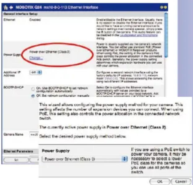
Variable PoE: Multiple cameras can be operated simultaneously from the same switch
LED default settings
1 Power (on),
Error (flashes)
2 Recording (flashes)
- Booting

- Key?

- Ready

2.7.9 Camera Startup Sequence
As soon as the camera's power supply has been established, the two LEDs will show the progress of the startup sequence (see Section 5.4.3, «LED Signals and LED Configuration», in the MOBOTIX Camera Software Manual Part 2).

- Booting: Immediately after connecting the power supply, the red LED lights up, blinks for two seconds, then stays on permanently red. The camera runs a self-test at this point, and starts the entire system after that. In case of an error, the camera will start using the backup system.
- Waiting for key pressed: Both LEDs light up for four seconds. If you press the R or L key of the camera during this time, the camera will execute the corresponding function (see Section 3.2.5, «Starting the Camera with the Factory IP Address» and Section 3.2.6, «Starting the Camera with an Automatic IP Address (DHCP)»). To press a key, use a paper clip for example, but never use sharp or pointed objects!
- Ready: Once the camera software is running, the green LED is on permanently and the red LED blinks. You can now reach the camera via the network (using a browser, MxControlCenter, MxEasy, MOBOTIX App, etc.).
Note
During the startup sequence of the camera, the LEDs will always light up, even if they have been deactivated in Admin Menu > LED Setup.
Notes
Download the free-of-charge MxEasy and MxControlCenter software at www.mobotix.com
Camera software in the browser
3.1 Manual and Automatic Operation – Overview
MOBOTIX cameras do not require any extra software. Thus, you can set up and operate the MOBOTIX camera using a JavaScript-enabled browser on all common operating systems (such as Windows, Linux, Macintosh, etc.). As an alternative, you can also use the MOBOTIX applications MxControlCenter and MxEasy. Follow these steps to set up the camera:
- Connect the camera to the network. Power is supplied directly via the Ethernet cable (see Chapter 2, «Installation»)
-
Set up the camera's network parameters:
-
Manually via a web browser (see Section 3.2.1, «Manually Setting Up the Network Parameters in a Browser» and below)
-
Automatically with MxControlCenter/MxEasy (see Section 3.2.3 and Section 3.2.4) or via DHCP (see Section 3.2.6, «Starting the Camera with an Automatic IP Address (DHCP)»)
-
Configure the camera using the web-based user interface, MxControlCenter or MxEasy.
Every MOBOTIX camera comes preconfigured with a static IP address in the 10.x.x.x range (for example, 10.8.0.99). However, local computer networks usually have IP addresses in the 172 or 192 ranges. In order to access a MOBOTIX camera via the network, the camera needs to obtain an IP address in the same address range. You can set up the network parameters of the MOBOTIX camera using one of the following methods: Manually, using MxCC and MxEasy or by DHCP.
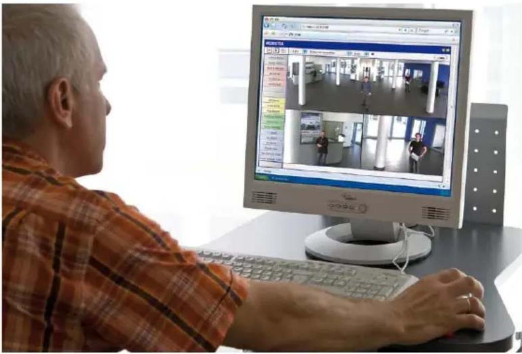
© MOBOTIX AG • Security-Vision-Systems • Made in Germany
3.1.1 Manually Using a Computer in the 10.x.x.x IP Address Range
You can set up the camera's network parameters using a browser and the embedded camera software. To do this, connect the camera to a computer or a network that is using a 10.x.x.x IP address range (see Section 3.2.1, «Manually Setting Up the Network Parameters in a Browser»). Once this has been completed, you can enter the camera's default IP address in the browser's address bar of the computer (see Section 3.2.2, «First Images and the Most Important Settings in the Browser»). Next, click on the Admin Menu button to open the camera's Quick Installation in the browser's user interface. This is where you can configure the desired network parameters of the camera. Once you have completed the Quick Installation, you can connect the camera with its new network parameters to the desired network.

Advantages
- The camera does not need to be physically accessible, that is, it may already be mounted.
- No additional software is required.
- The network parameters can be set flexibly through manual entry.
Disadvantages
- The computer or the network needs to operate in the 10.x.x.x IP address range or need to be able to access such a network.
- The setup does not work automatically.
- You need to know the relevant network parameters.
MxControlCenter software (free download from www.mobotix.com)
MxEasy (free download from www.mobotix.com)
3.1.2 Automatically Using MxControlCenter or MxEasy
You can set up the camera's network parameters using the free-of-charge video management software MxControlCenter or MxEasy (see Section 3.2.3 and Section 3.2.4). You can also use one of these applications to automatically configure the network parameters of MOBOTIX cameras that are not operating on the same IP address range as the computer.
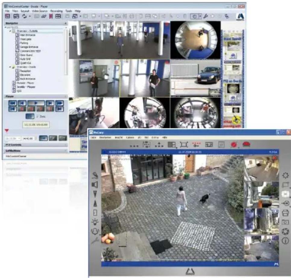
Advantages
- You can connect the camera directly to the target network.
- The camera does not need to be physically accessible, that is, it may already be mounted.
- The camera can be configured to automatically receive an IP address (optional).
- The network parameters can be manually set (optional).
- You do not need to access the camera software.
Requirement
- Either MxControlCenter or MxEasy must be installed on the computer.
3.1.3 Automatically Using DHCP
The camera can automatically obtain its network parameters using DHCP (Dynamic Host Configuration Protocol). This requires the network to have a functioning DHCP server (for example, a DSL router with activated DHCP server) and the camera must be booted using DHCP (see Section 3.2.6, «Starting the Camera with an Automatic IP Address (DHCP)»). The IP address automatically assigned by the DHCP server will be announced via the camera speaker as soon as the camera has booted successfully.
Advantages
- You can connect the camera directly to the target network.
- Network parameters are automatically assigned.
- No additional software is required.
- You do not need to access the camera software.
Disadvantages
- The camera needs to be physically accessible as you need to press a key on the camera housing to boot it using DHCP.
- Requires a running DHCP server on the network.

natural_image
Close-up of a white smart security camera with blue trim and a small blue S23 card attached (no visible text or symbols on the device body)Pressing the "L" key (see Section 3.2.5) will prompt the camera to announce its current IP address on the camera speaker
Entry in "Subnet mask" field: 255.0.0.0
3.2 First Images and the Most Important Settings
Once the MOBOTIX camera has been connected to the network, you need to set up the camera's network interface accordingly. This step involves setting up and checking the network parameters of the camera. If your network is already using an IP address in the 10.x.x.x range with a 255.0.0.0 network mask, you do not need to change the camera's network parameters. You can access the camera directly (see Section 3.2.2). If your network or computer does not use an IP address in the 10.x.x.x range (for example, in the 192 or 172 ranges), you should follow one of the following methods for changing the camera's network parameters:
- Manual Setup (see Section 3.2.1)
- Automatic setup using MxControlCenter or MxEasy (see Section 3.2.3 and Section 3.2.4)
Note
We will use a camera with the factory address 10.8.0.99 in the following examples. Replace this IP address with the IP address of your camera. You will find the IP address of your camera on a small sticker on the camera. Make sure that the IP addresses used in the following examples are not already being used by other devices in the network.
3.2.1 Manually Setting Up the Network Parameters in a Browser
You need a computer that is using a 10.x.x.x IP address in order to manually set up the network parameters of the MOBOTIX camera. The computer's network parameters usually have to be changed for this purpose.
1. Change the network parameters of your computer:
Windows (XP, Vista and 7):
- Open Start > Settings > Control Panel > Network Connections. Clicking on Properties opens the dialog box shown.
- Double-click on Internet Protocol (TCP/IP). On the General tab, activate the Use the following IP address option. Enter an IP address in the 10.x.x.x range in this field (for example, 10.8.0.11).
- Once all dialog boxes have been closed, the computer will have the IP address 10.8.0.11.
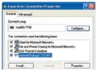
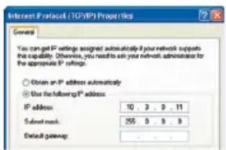
Linux/Unix:
- Open a terminal as root user.
- Enter the following command: ifconfig eth0:1 10.8.0.11
- The computer is now also using the IP address 10.8.0.11
Mac OS X:
- Open System Properties > Network.
- Select Ethernet. In the Configuration field, select Manual and enter a 10.x.x.x IP address (for example, 10.8.0.11).
- Click on Apply on the bottom right-hand side of the dialog box to assign the computer the IP address 10.8.0.11.

2. Set Up the Target Network Parameters of the MOBOTIX Camera:
- Open a web browser on the computer and enter the default IP address of the MOBOTIX camera in the address bar of the browser (for example, 10.8.0.99). Pressing Enter displays the user interface of the MOBOTIX camera (see also Section 3.2.2, «First Images and the Most Important Settings in the Browser»).
- Click on the Admin Menu softbutton in the user interface of the MOBOTIX camera.
The Quick Installation starts automatically once the admin user has logged on.

Note: The Quick Installation can also be executed at a later stage by opening Admin Menu > Network Setup > Quick Installation (see also Quick Installation in the Camera Software Manual Part 2).
- Enter the target network parameters of the camera on the appropriate page of the Quick Installation assistant.
Note: The network parameters can also be modified retrospectively via Admin Menu > Network Configuration > Quick Installation.
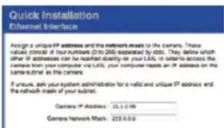
- Once you have completed the Quick Installation and rebooted the camera, the new network parameters will be activated. The camera can now be connected to the target network and, if required, further configured.
3.2.2 First Images and the Most Important Settings in the Browser
Once the MOBOTIX camera has been connected to the power supply and to the network, you can access the user interface with the live camera image in the web browser. Internet Explorer, Firefox, Safari or any other graphical browser with activated JavaScript is suitable. It does not matter which operating system is used.
After entering the camera's IP address in the browser's address bar, you will see the live view of the MOBOTIX camera with its user interface controls, such as softbuttons, buttons for the different camera screens, pull-down menus (Quick Controls), icons for accessing the online help and the camera status, and status information elements.

Note
Default access data for the administration menu
- User name: admin
- Password: meinsm
Camera Views: Live, Player, MultiView
The MOBOTIX camera automatically displays the live screen when it starts up (factory default setting). You can set a different start page in Admin Menu > Language and Start Page (for example, the Guest screen) to allow a restricted access to the live image.

The other available standard screens include Player (playback of recorded images and video sequences) and the MultiView screen (displays several cameras with live or recorded images).

MultiView allows you to view several cameras via a "proxy" camera (especially useful if you want to access your cameras from outside of the network with reduced bandwidth) and the PDA mode provides a special screen for mobile devices.

Note
For more information on camera screens, see Section «Camera Screens In The Browser» in the Camera Software Manual Part 2 or the online help of the camera's user interface.

Live view:
http://
control/userimage.html

Player screen:
http://
control/player

MultiView screen:
http://
control/multiview
PDA screen:
http://
PDA event list:
http://<camera
IP>/control/
player?eventlist&pda
Guest screen:
http://
cgi-bin/guestimage.html
Download MxControlCenter for free from www.mobotix.com
3.2.3 First Images and Network Parameter Configuration in MxControlCenter

Installation
Download the setup file from the MOBOTIX website to install the latest version. The latest versions are available at www.mobotix.com in the Support > Software Downloads > MxControlCenter section.
To install MxControlCenter, simply double-click on the setup file and follow the instructions.
The selected files are copied to the computer (older versions will be removed automatically) and the designated shortcuts are created during the installation process (Desktop, Start Menu, etc.).
Caution
MxControlCenter will automatically attempt to find all MOBOTIX cameras in the physically-connected network (that is, even a MOBOTIX camera with a factory IP address of 10.x.x.x). Make sure that the firewall settings on your computer are low enough so that MxControlCenter is not blocked. If any MOBOTIX cameras are found, MxControlCenter can automatically reconfigure them so that they are available in the current subnet of the computer. If you do not have permission to modify these settings on your computer, contact your system administrator for assistance.
MOBOTIX- Searching and Displaying MOBOTIX Cameras
Launch MxControlCenter after successful installation by double-clicking on the shortcut that was created during installation or the executable file MxCC.exe in the installation directory on your computer.
The Add Video Sources dialog box appears and the application automatically searches for MOBOTIX cameras in the local network when you launch the program for the first time. Select Video Source > Add from the menu to perform a camera search at a later time.
If your MOBOTIX camera is properly connected, it should appear together with the existing video sources in the following list:
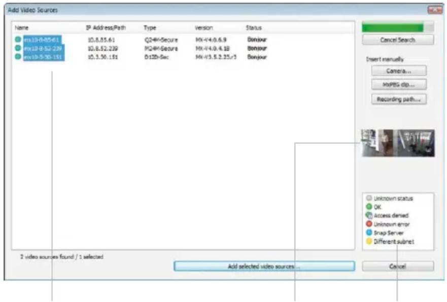
List of video sources LegendCamera preview
Note
Video sources in this context not only refer to MOBOTIX cameras, but also to third-party IP cameras, file server paths, MxPEG clips and analog cameras connected via MxServer (for example, analog dome cameras). These video sources are not found automatically and need to be added manually.
Cameras Are Found But Are Located in a Different Subnet
The symbols in the first column and the legend in the dialog box indicate whether you can access a particular camera directly from the MxControlCenter, which is the case for all cameras designated with (OK). Cameras designated with (different subnet) are located in a different subnet. This usually applies to new cameras or cameras that have been reset to their factory settings.
Note
MxControlCenter finds all MOBOTIX cameras, even when the computer and the cameras are not located in the same subnet.
Once you have marked all of the desired video sources in the list with OK, you can now select the ones that you wish to display and manage in MxControlCenter. The live image is automatically displayed in the preview window when a camera is selected to help you identify the cameras.
For cameras marked with Different subnet or if you want to add additional video sources, follow the instructions in the following sections. You can also display the selected cameras directly in a layout. For more information, see «Creating a New Layout» further down.
Reconfiguring Cameras in a Different Subnet
If one or more MOBOTIX cameras are displayed with the status Different subnet (for example, cameras with a factory IP address), MxControlCenter automatically offers to configure the network settings of these cameras. In this case, the application displays the dialog box shown here after you have clicked on the Add selected video sources button. Click on Yes to configure the cameras to the subnet of the computer.

A DHCP server automatically assigns IP addresses for network devices in most networks so that you can automatically select the default setting Get IP address automatically (DHCP) in the Configure Selected Cameras dialog box.
Activate the Use this IP address/this range option if the IP address of a particular camera must be assigned manually (for networks with static IP addresses). Obtain the assigned IP address, subnet mask and standard gateway from your network administrator and enter the data. All you have to do is enter the range of IP addresses that includes the addresses of all of these cameras to reconfigure multiple cameras at the same time.

Make sure that the Store configuration in the camera checkbox is selected. This setting ensures that the cameras are displayed with the correct network settings even after they have been rebooted. Click on OK to close the dialog box.
Wait until MxControlCenter has changed the network settings and rebooted the cameras. The status of the reconfigured camera changes from (Different subnet) to (OK).
Defining Additional Video Sources
In addition to the MOBOTIX cameras that are found automatically, you can also manually add video sources to the list of video sources for MxControlCenter.
- Camera: Here, you can enter the known IP address or DNS name of a MOBOTIX camera or a third-party IP camera if it was not found by the automatic search feature.
- MxPEG clip: Adds an MxPEG video clip previously recorded by a MOBOTIX camera as a video source.
- Recording path: Adds the path of an external file server where a MOBOTIX camera has recorded audio/video data. The videos or images recorded at that location can now be played back using the Player or Video Search.
Editing the Video Source List
Right-click on this list to open a shortcut menu from which you can select all video sources or cancel the selection. You can also use this method to remove from the list some or all of the video sources that you would not like to display or manage in MxControlCenter.

If you have cancelled the camera configuration process or need a password that differs from the camera's factory default password, you can also configure the camera from the shortcut menu at a later date and enter the user name and password required for reconfiguration at that time.
It is also possible to open the Configure selected cameras dialog box using the shortcut menu in order to change the camera network parameters.
Creating a New Layout
Select the camera or other video sources that you would like to display in a layout (a view with a group of selected cameras) in the Add video sources dialog box and then click on Add selected video sources.

The Create new layout dialog box is displayed. If you select the Generate new grid for selected video sources option here, MxControlCenter automatically generates a grid layout that displays windows of the same size for all selected video sources. Give each layout a unique name (for example, underground garage).
If you select the second option, the video sources you selected are simply integrated in the MxCC system where you can use them to generate a layout at a later time.
Click on OK to confirm.
3.2.4 First Images and Network Parameter Configuration in MxEasy
Installing and Starting MxEasy
Download the current version of MxEasy from the MOBOTIX website (www.mobotix.com > Support > Software Downloads in the MxEasy area). Double-click the shortcut for the program or the program file.
Finding Cameras
When you start MxEasy for the first time on a computer, the MxEasy Assistant automatically begins to search for MOBOTIX cameras and displays all cameras found in a list. The camera list will be updated automatically as soon as new MOBOTIX cameras are connected to, or removed from the network.

MxEasy also automatically monitors and displays the operating status of all cameras. Cameras that are not on the same subnet as the computer will get a differently colored symbol than the cameras that are on the same subnet. Likewise, the cameras that have an unknown password or for which no user name/password combination has been specified in MxEasy will be displayed in a different color. The following section "Reconfiguring Network Addresses Of Cameras" contains information about cameras with the status Invalid network (for example, all new MOBOTIX cameras with factory settings).
© MOBOTIX AG • Security-Vision-Systems • Made in Germany

Download MxEasy for free from www.mobotix.com
*Bonjour: automatic recognition of network services in IP networks
Reconfiguring Network Addresses of Cameras
Using Bonjour*, MxEasy finds not only cameras on the same network as your computer, but also MOBOTIX cameras located in other subnets (the Invalid Network status). In such a case, you would not be able to establish any connection to cameras in a different network or subnet (without going into much further detail regarding TCP/IP network configurations). This is possible, for example, when a camera with a factory IP address is connected to a network in which a DHCP server automatically assigns the IP addresses. MxEasy can automatically configure such a camera so that it is "integrated" into your existing network. To do so, you only have to select the affected camera in the list and then click on Continue.
After a security prompt, a new dialog box for configuring the selected camera is displayed.

If your computer automatically obtains its IP address from a DHCP server, then this is certainly the best choice for that specific camera and most likely for all other cameras that have been found in a different subnet (Get IP address automatically option).
If you have assigned a static IP address to your computer, you will probably want to assign static IP addresses (issued by your system administrator) to every camera (the Use this IP address option). Normally, you enter the same configuration used for the network settings of your computer.
When you click on OK, the selected cameras are automatically reconfigured and they are located in the same subnet as the computer.
Integrating and Displaying Cameras
After a camera has been reconfigured, it has the status Accessible and can be integrated into MxEasy. The MxEasy Assistant then displays the Define Integration Mode in MxEasy dialog box.
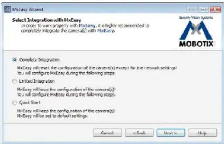
Here, you can jump directly to the main window of MxEasy with the current live camera image by activating the option Quick Start. However, some required detailed configurations may have to be made at a later time (for example, password protection, available bandwidth). For this reason, we recommend activating the option Complete integration and complete the remaining dialog boxes of the MxEasy Assistant until the main window appears.
If one of the integrated cameras includes a M25M, the MxEasy Assistant opens an additional page where you can specify the mounting positions (Ceiling, Wall, Floor) and display modes (Panorama, Surround, etc.) of the individual sensor modules.
After you are done with the MxEasy Assistant, the application's main window appears and displays the first camera:
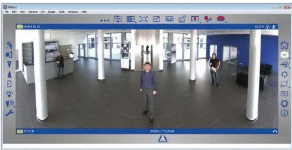
natural_image
Interior view of a modern office lobby with three people walking, featuring white columns and blue walls (no visible text or symbols)For more information, see the MxEasy User Manual, which can be downloaded as a PDF file from the MOBOTIX website: www.mobotix.com > Support > Manuals.
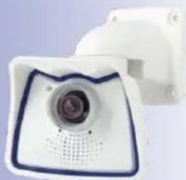
natural_image
Close-up of a white electronic device with a circular lens and blue border (no visible text or symbols)Main window with Panorama image of a M25M
Passwords and camera settings will not be changed
3.2.5 Starting the Camera with the Factory IP Address
Under certain circumstances, you may have to reset the camera to its factory IP address. This could be the case, for example, if the IP address has been lost or the camera does not respond to the last known IP address. Proceed as follows to start up the camera with its factory IP address:
- If the camera is powered on, disconnect the power supply by unplugging the corresponding cables and then reconnect the power supply.
- Wait until both LEDs light up simultaneously for the first time.
- Press the L key within the next four seconds and hold it down (if you need to try again, go back to Step 1). Use a paper clip for this purpose but avoid using sharp or pointed objects!

- After about 30 to 45 seconds, the camera emits a single sound ("boing").
The camera has finished booting and can now be used (e.g., MxEasy, MxControlCenter, MOBOTIX App, web browser).
Make sure you store the default network configuration to the permanent flash memory
Notes
If you use the camera's L key to load the factory network configuration, this configuration is not automatically saved in the camera's flash memory. When the camera is next rebooted without using the L key, the last stored network configuration will be used. To permanently store the new network configuration in the camera's flash memory, open Admin Menu > Store.
As opposed to resetting the camera using Admin Menu > Reset configuration to factory defaults, the user information will not be reset if the camera is booted using the factory IP address.
3.2.6 Starting the Camera with an Automatic IP Address (DHCP)
If your network has a DHCP server, you can start the MOBOTIX camera with DHCP support. The camera automatically obtains an IP address from the DHCP server and announces the new network data. Please note that this announcement can only be heard if the camera is connected to an external speaker.
- If the camera is powered on, disconnect the power supply by unplugging the corresponding cables and then reconnect the power supply.
- Wait until both LEDs light up simultaneously for the first time.
- Press the R key within the next four seconds and hold it down (if you need to try again, go back to Step 1). Use a paper clip for this purpose but avoid using sharp or pointed objects!
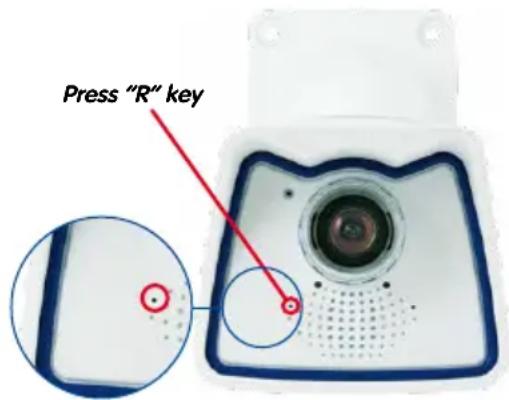
- After about 30 to 45 seconds, the camera emits a double sound ("boing boing").
The camera has finished booting and can now be used (e.g., MxEasy, MxControlCenter, MOBOTIX App, web browser).
Notes
Starting the camera with an automatic IP address (DHCP) is only temporary. The network configuration of the camera can be permanently set to DHCP under Admin Menu > Ethernet Interface.
Make sure that the network has a functioning DHCP server when starting the camera with DHCP support. If this is not the case, the camera cannot obtain a valid IP address and will use its last IP address.
You should also make sure that the cameras always obtain the same IP addresses by permanently assigning the MAC addresses of the cameras to the desired IP addresses.
In case of an error, the camera uses its last IP address
3.3 Virtual PTZ and Full Image Recording
3.3.1 Preparing the Virtual PTZ Function
The virtual PTZ function allows you to use a mouse or joystick to continuously zoom in on images from the selected video source and "virtually" move the enlarged image section within the entire image sensor area.

natural_image
Close-up of a red and black mechanical knob or knob on a dark base, against a light blue background (no text or symbols visible)Greater ease of use through a joystick
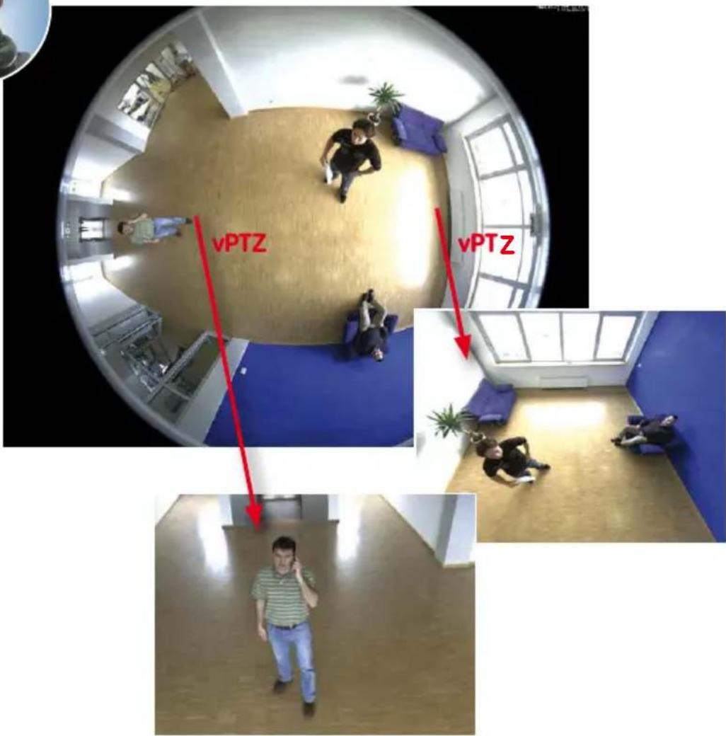
Operation Using The Mouse And Scroll Wheel
The vPTZ function of the M25M can be controlled in the browser using the mouse. This position becomes the new image center by clicking on any position on the image displayed on the monitor. The image moves accordingly and the image distortion is automatically corrected. The scroll wheel can be used to control the zoom function. This functionality is disabled in the default settings of the camera and must therefore first be activated. To do this, go to Setup Menu > vPTZ Settings, disable Lock Mouse Wheel Zoom, click on Set and then on Close to save your settings. You can now use the scroll wheel to zoom + (roll upwards) or zoom - (roll downwards).
Operation Using USB Joystick
A standard USB joystick can drastically improve vPTZ operation for the user – in the browser, in MxEasy, and in the MxControlCenter (however, MxCC is also equipped with a virtual joystick that can be operated using the mouse). Please first install the joystick on the PC according to the manufacturer's instructions.
In order to use a USB joystick in the browser, make sure that you have a PC with a Windows operating system and the latest version of Internet Explorer and that the "ActiveX" mode in the camera software (browser) is activated:
- Switch to Browser in the Quick Control.
- Under Browser, select the option ActiveX in the field to the right. The USB joystick can then be used until the browser is closed.
- To store the setting permanently, ActiveX must be activated in the Admin Menu. To do so, use Language and Start Page in the Admin Menu.
• Under the page options, select the ActiveX operating mode. - Store the settings permanently in the camera by clicking on Set and Close.
• The joystick can now be used.
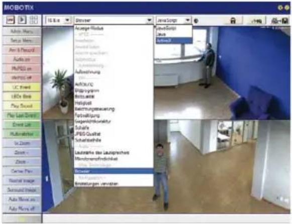

Notes
You will find more information and details on vPTZ in the Camera Software Manual Part 2, Section 4.3.6, «Virtual PTZ», the MxEasy manual, Section 2.4.1, «Activating the PTZ Features», the MxControlCenter manual, Section 2.4.6, «Using the vPTZ Features» and Section 3.1.4, «The "PTZ Controls" Section In The Sidebar Panel».
Current versions of all manuals can be downloaded anytime from the MOBOTIX website www.mobotix.com under Support > Manuals).
Virtual joystick in MxControlCenter

natural_image
Pure graphical icon of a circular button with directional arrows and control buttons (no text or symbols)3.3.2 Full Image Recording
It is possible to record a full image, regardless of the live image stream that is being displayed. This ensures that the recording always contains the full image of the lens used, even though the operator may have used the vPTZ features to zoom into the image in order to examine a specific detail.

natural_image
Interior view of a modern office hallway with a person standing near a door and a red arrow pointing to the floor (no visible text or symbols)Live image Stored Full In
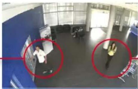
natural_image
Interior view of a modern office or campus space with two people in the foreground, one holding a device and another standing nearby (no visible text or symbols)ge Analysis in stored full image
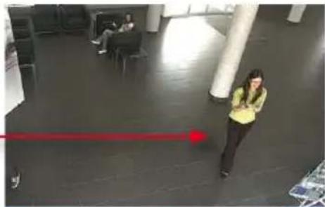
natural_image
Interior view of a modern office or library space with a person standing near a large pillar and a red laser beam (no visible text or symbols)
Stored full image: Original camera image without distortion or image correction
This means that you can use the vPTZ features in VGA resolution to pan, tilt and zoom in the live image while the camera is, for example, recording full images at 1 fps in MEGA or 5MP resolution.
In MxEasy or MxControlCenter, the recorded full images may be prepared for the user with the vPTZ functions (for example, panning and zooming in on an image detail such as a doorway).
If full image recording is not activated, only the last displayed live image will be saved (save what is seen). The main benefit of live image storage is to ensure that the full power of the camera processor is used for live image correction and maximum frame rates. The main advantage of full image recording lies in the special functionality of the D14D, in that it can always ensure the availability of a maximum size (full) image for later searches, despite vPTZ actions carried out on the live image. The mechanical limitations of motor-driven PTZ cameras mean that they simply cannot provide this unique advantage to the user!
Notes
Post-event search in the full image: If you are using Full Image Recording on D14D cameras, you should use at least MEGA resolution when storing. This will facilitate later searches in MxControlCenter or MxEasy. The advanced distortion correction features require this function to deliver satisfactory image quality.
Full image recording on: Due to the increased processing time, full image recording reduces the data rate of the live image stream, which may drop by around 10 to 30 percent. We therefore recommend reducing the frame rate for storage as much as possible to affect the live image stream as little as possible.
Full image recording off: The event that triggered a video motion (VideoMotion VM) window may not be in the recorded sequences while the window was not displayed at the time.
Activate/Deactivate Full Image Recording in the Browser
To configure this feature, open the Setup Menu > Event Control > Recording dialog box and activate or deactivate the Full Image Recording option.
![MOBOTIX Q24 mx10-8-0-113 Recording General Settings Value Explanation Arming Enable Arm Recording: Controls camera recording: Enable: activate Recording. Off: deactivate Recording. SI: Recording armed by signal Input. CS: Recording armed by custom signal as defined in General Event Settings. From Master, copies Recording arming state from master camera. (no time table) Time Table Profile: Time table profile for time-controlled recording. (Time Tables) Digital Signing Off Digital Signing: Digitally sign the recorded image files using the X 509 certificate of the web server. Manage X 509 certificates of the web server. Recording Status Symbol Off Activate Recording Status Symbol On will draw a symbol in the image to visualize the current arming and recording status. Full Image Recording On Activate Full Image Recording: On will save record the full image of the sensor with the specified parameters. On will record the visible image. Terminate Recording (TR) Off Activate Terminate Recording: Terminate recording if an event is detected. Use this option to freeze stored images. Click here to resume recording. Storage Settings Value Explanation Recording (REC) Event Recording Recording Mode: Type of event and story recording Snap Shot Recording stores single JPEG pictures. Event Recording stores stream files for every event using MxPEG codec. Continuous Recording continuously streams videodata to stream files using MxPEG codec. Include audio Record Audio Data: Store audio data in stream file if available. Enable and configure microphone Start Recording Select the events which will start recording. Use [Ctrl] - Click to select more than one event. Events in brokets need to be activated first. EC or EL for filtered events. Set Factory Restore Close Less](/content/2026/05/1027552/images/ba1a9fe51ecf41fa28b3bdbbef35b3d3757a7b28bfcb8ff4c7695481cb845dcf.jpg)
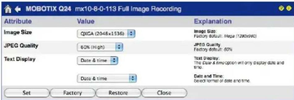
3.3.3 Special M25M Configuration in the Browser
Thanks to its hemispherical lens, the MOBOTIX M25M provides certain special configuration options for the image settings. Depending on where the camera is mounted (ceiling or wall) and on the live image display preferred by the user, certain important basic settings and, if necessary, their adjustment must be configured when a M25M is first installed.
A corresponding adjustment of the image setting is strongly recommended if the on-wall set is mounted with an inclination of 10 degrees (available as a M25M accessory).
Configuration of the M25M Basic Parameters
Complete the steps described below in the browser window:
-
Log onto the camera and boot it as described in Section 3.2.
-
Select mounting position wall/ceiling/floor: Click on Installation in the Quick Control panel and then select Wall, Ceiling or Floor according to the mounting position of the camera. Ceiling always means that the orientation of the camera or sensor module is from top to bottom and for Floor, the camera or sensor module's orientation is from bottom to top.

As a result, you will get a perspective-corrected panorama view for each image sensor matching the specified mounting position. Panorama view is set as a factory default and it can be changed as described below.
-
Switch to the Display Mode Quick Control.
-
Set the mode that you want to be the standard view. For demonstration purposes, the descriptions below describe the typical display mode for the wall mount and the ceiling mount, Panorama and Surround respectively. Every other display mode can be operated in the same way.
Wall-Mounted: Setting and Correcting the Standard View "Panorama"
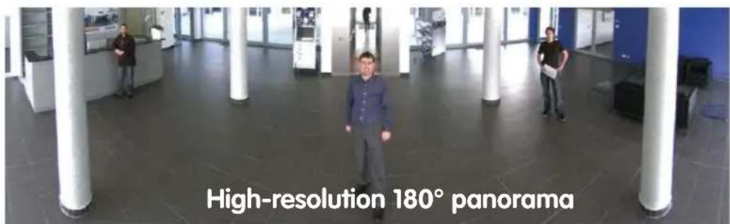
High-resolution 180° panorama
amayonang 08r nothology-midh
- In the Display Mode Quick Control, select the option Panorama. Examine the image that is now displayed. If the section meets your expectations, no further adjustment is necessary, and panorama configuration is complete. To change the image section to meet your specific expectations, continue with Step 2.

Note
The currently visible image section may differ from the desired image section due to the installation position or any accessories in use, for example. However, it is not necessary to physically move the camera, as in this case the browser alone can be used to adjust the visible panorama image by zooming, panning and tilting. Tilted vertical lines may also be optically straightened to the image edges using the panorama correction function. These tilted lines are primarily caused if the camera or sensor module is tilted (for example, due to mounting with 15^ wedges) or if the image tilt is modified.
Camera live image with panorama correction
Camera live image without MOBOTIX panorama correction with Quick Controls visible
112/136
M25M Camera Manual: Operating the Camera
Open lock
Click on the icon
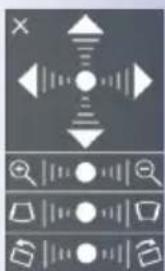
natural_image
Pure graphical icons without any text, numbers, or symbolsCamera live image with panorama correction with OnScreen Control visible
- Click on the lock icon. Clicking on the lock once opens it (lock clasp is raised). The lock prevents execution of later vPTZ actions, which could also unintentionally modify the view you configure. This holds for all overview display modes, that is, also for Panorama/Focus, Double Panorama and Surround.

- A new icon for processing the panorama image appears in the top left corner of the camera image. Enlarge the image by clicking on the icon once (OnScreen Control appears).

- Using the OnScreen Control visible in the live camera image, you can now change the displayed live camera image as desired (panning, tilting, zooming, rotating and panorama correction; see fig. on the right). When doing so, the vPTZ function using the mouse or joystick is deactivated.

- After you have modified the desired setting, close the control panel (x in the top left hand corner).
- Click on the lock icon again to close it (lock clasp is down). The panorama image setting is then locked until the camera is next restarted.
Caution
To permanently save the standard image setting defined for the M25M, go to the Store Complete Configuration option in the Manage Settings Quick Control. The settings will then remain in effect, even after rebooting.
© MOBOTIX AG • Security-Vision-Systems • Made in Germany
Functions of the M25M OnScreen Control

To use the OnScreen Control, click on the arrows in the top area for shifting the image section. In the bottom areas, which are displayed when needed, click to the left and/or right of the center point.
The same applies for every area: The further away that you click from an area's center point, the greater the change triggered. To reset an area, click on its center point again.
During panorama correction, clicking between the two trapezoid symbols straightens the left or right tilting lines, which are best visible at the edges of the image section.
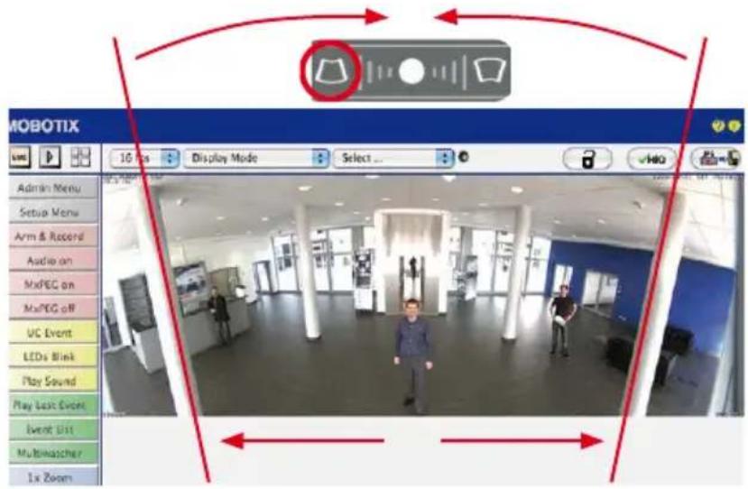
Depending on the mounting position (ceiling, wall, floor), panorama correction and mounting error correction may not be available!

Bring columns together at the top (necessary to correct the example on the left)

Bring columns together at the bottom
Ceiling-Mounted: Set North (User-Defined North Direction)
Once the camera has been mounted on to the ceiling, you need to specify its North direction. This is not the "true" direction of North but rather the main line of sight or the focus of the camera or sensor module. It serves as a reference for the North direction in the Surround and Double Panorama display modes (the Ceiling option was already selected in the Installation Type Quick Control).
- In the case of a double image, click on the corresponding sensor module (camera image) and select the Normal option from the Display Mode Quick Control.

For vPTZ use and the configuration of a USB joystick, see Section 3.3.1
- Rotate the live image in the desired direction using the mouse or a joystick connected to the computer.
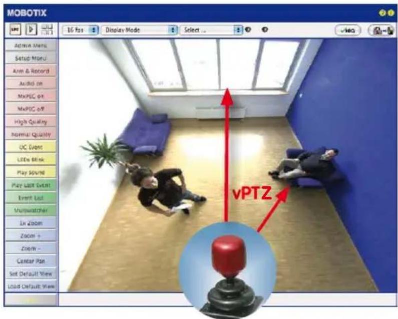
- In the Installation Quick Control, select the Set North option.

- Store the desired North direction permanently by first activating the checkbox and then clicking on Yes.
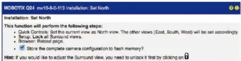
- You have now set the North direction for the Surround and Double Panorama display modes. In the next step, you can set these views as the standard view for the camera live image.
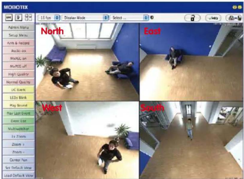
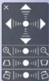
natural_image
Pure UI icons without any text, numbers, or symbolsIn the Display Mode Quick Control, select the option Surround or Double Panorama. You can fine-tune the views using the vPTZ via mouse or joystick and, as described above, by unlocking and locking the standard view using the lock icon (open lock, correct display and close lock again).
Note
For each of the subviews (North, East, etc.), the OnScreen Control on the side can be used to adapt it (open lock, click on subview, adapt view, click on next subview, adapt view and close lock again).
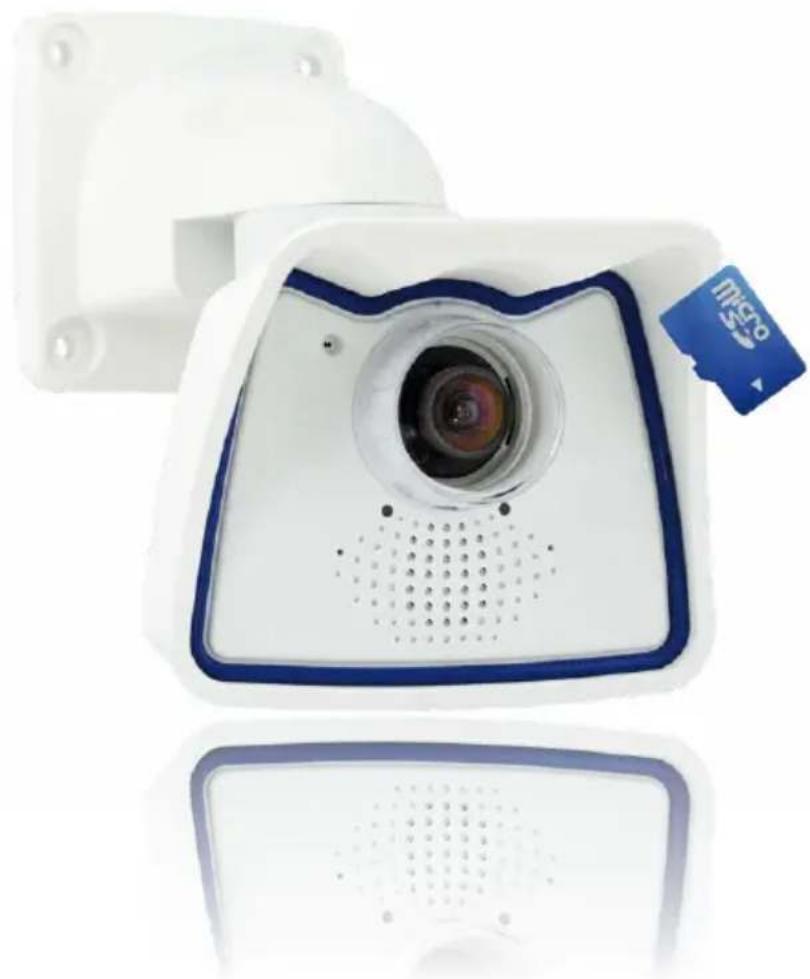
natural_image
White digital camera with blue frame and a small card labeled 'micro' (no text or symbols on device body)3.4 MicroSD Card Recording
3.4.1 Introduction
Flash-based storage devices (MicroSD cards, USB sticks and solid-state drives) do not contain any moving parts as compared to the commonly used hard drives. Flash-based storage devices are compact and highly resistant to moisture and vibrations. They feature low energy consumption and they do not lose any data in the event of a power failure, meaning that they are ideal for use with MOBOTIX cameras.

Number of Write/Delete Cycles Per Flash Storage Cell
The number of write/delete cycles of every storage cell of a flash device is limited. The controller of the flash device automatically
detects individual flash cells that are no longer functioning. The contents of the faulty cell will then be rebuilt using a checksum and will be moved to a properly working spare cell. The faulty storage cell will be marked as "bad" and will no longer be used. No data is lost in this process.
In addition, MOBOTIX cameras constantly monitor activated flash storage devices. MOBOTIX has developed a technology to test the wear of the flash device by logging the number of write/delete cycles (patent pending). The flash memory wear is automatically displayed in the status bar in the live camera image but it can also be viewed at any time in the Admin Menu > Camera Status dialog box.
Conservative Memory Usage Thanks to MOBOTIX MxFFS File System
MxFFS formatting of the MicroSD card means that MOBOTIX camera software will use the flash device as evenly as possible, thus allowing for the maximum possible number of write/delete cycles. This also means that all storage cells of the flash device will be written and deleted with the same frequency, if possible. MOBOTIX technology increases the life of the flash device considerably and also improves the security and the reliability of the storage process.
Storage Requirements and Life Expectancy of MicroSD Cards
The life expectancy of a MicroSD card increases proportionally to the storage capacity, since the camera software will execute fewer write/delete cycles on each storage cell. The first deletion will begin once the SD card has been filled to capacity (first full cycle).
Flash memory devices: more robust than hard drives
All specifications are based on calculated averages
32 GB MicroSD Card: Storage Requirements
| 6 fps CIF 6 fps VGA 1 fps MEGA 1 fps QXGA | |||||
| M-JPEG M-JPEG MxPEG M-JPEG M-JPEG | |||||
| File size single image 15 kB 45 | kB – 120 kB 240 kB | ||||
| Storage required per second 90 | kB 270 kB 75 | kB 120 kB 240 kB | |||
| Storage required per 24 hrs 7.8 | GB 23.5 GB | 6.5 GB 10 | 4 GB 20.8 GB | ||
| Time for one full cycle | 4 days | 1.3 days | 4.8 days | 3 days | 1.5 days |
4 GB MicroSD Card: Storage Requirements
| 6 fps CIF | 6 fps VGA | 1 fps MEGA 1 fps | QXGA | ||
| M-JPEG | M-JPEG | MxPEG M-JPEG | M-JPEG | ||
| File size single image 15 kB 45 | kB – 120 kB 240 kB | ||||
| Storage required per second 90 | kB 270 kB 75 | kB 120 kB 240 kB | |||
| Storage required per 24 hrs 7.8 | GB 23.5 GB | 6.5 | GB 10.4 GB 20 | 8 GB | |
| Time for one full cycle | 12 hours | 4 hours | 14.4 hours | 9.2 hours | 4.4 hours |
Caution
The MicroSD card's service life depends on production quality and frequency of use. Set the type of recording (event-controlled or continuous recording, frame rate, resolution) according to your specific requirements.
We recommend changing the pre-installed, high-quality MicroSD card once a year if you have it constantly set to continuous recording.
Monitoring The Cell Wear Of Flash Storage Devices (Patent Pending)
MOBOTIX uses its own technology for this purpose and has a pending patent. You can view the flash wear in the status bar of the live image or by opening Admin Menu > Camera Status. In addition, the camera can also send a warning message (for example, via e-mail) as soon as a critical error is detected when data is written to the SD card (Admin Menu > Error Notification Function.). The MicroSD card can then be replaced to ensure that any existing data is not lost.
| File Server / Flash Device | |
| Type | SD Flash Card |
| File System | MxFFS |
| Flash Wear | 1% |
| Transfer Buffer Usage | 0% (0: 0%, max: 0%) |
| Lost Event Images | 0 |
| Sequences | 1 (1 files) |
| Newest Sequence | 1970-01-01 01:00:00 #0 |
| Oldest Sequence | 1970-01-01 01:00:00 #0 |
| Current Usage | 4.0 MBytes (0.4%) |
| Max. Size | 936 MBytes |
3.4.2 Formatting the MicroSD Card
Before a MOBOTIX camera can store image and video sequences on a MicroSD card, the card needs to be formatted as MxFFS (MicroSD cards supplied by MOBOTIX are already MxFFS-formatted). The following steps are necessary to format a storage device (Admin Menu > Storage on External File Server / Flash Device):
- Make sure that there is a MicroSD card in the card slot of the MOBOTIX camera.
- Click Format in the SD Memory Card line.
- Note down the characters shown in the Encryption password field or enter your own password. Next, click OK.
Note: The Secure deletion – Slow option will ensure that any data on the MicroSD card is overwritten completely so that the data cannot be recovered in any way. However, keep in mind that this kind of safe formatting takes considerably more time.
- In the next dialog box, enter the user name and the password of a user of the admins group and click OK to confirm.
The MOBOTIX camera now starts formatting the card. It takes 5 to 12 minutes to format an 8 GB MicroSD card if the Secure deletion – Slow option is disabled. If Secure deletion – Slow is enabled, this may take anywhere between 3 and 14 hours.

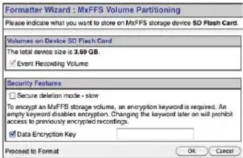

Once the formatting has been completed, you can activate the MicroSD card for recording (see next section).
Caution
Make sure that you always wait until the formatting process has been completed before accessing the camera again. If the Secure deletion – Slow option is disabled, this usually takes just a few minutes. You can only access the MicroSD card once MxFFS formatting has been completed.
Formatting with the Secure deletion – Slow option enabled takes several hours. You can also use suitable applications on Windows, Linux/UNIX and Mac OS X systems to repartition and safely erase the MicroSD card.
Format SD card:
Admin Menu > Storage on External File Server / Flash Device
The Secure deletion - Slow option takes several hours. You can also use suitable applications on Windows, Linux/UNIX and Mac OS X systems to repartition and safely erase the SD card.
Activate recording:
Admin Menu >
Storage on External File
Server / Flash Device
3.4.3 Activating MicroSD Card Recording
Follow these steps to activate the recording to a MicroSD card that has already been MxFFS-formatted (Admin Menu > Storage on External File Server / Flash Device):
- Make sure that there is a MicroSD card in the card slot of the MOBOTIX camera.
- Make sure that the MicroSD card is formatted in MxFFS format.
- Activate the SD Flash Card option.
- Click on Set and then Close to store the configuration.
- Reboot the MOBOTIX camera (Admin Menu > Reboot Camera).
Once the camera has rebooted, make sure that the camera displays the FR REC symbols in its live image. If this is the case, the camera uses the MicroSD card as recording target. If not, you must activate the recording (see below).
Activating the Recording
If the FR REC symbols are not visible in the live image after rebooting, you need to activate the recording using one of the following methods:
- In the web browser: Automatic activation by clicking on the Arm & Record softbutton. Confirm this in the Easy Dialog by clicking on the Yes button.
- In the web browser: Manual activation via the Quick Control Recording > Recording on or in Setup Menu > Recording.
- MxEasy: It is possible to activate the recording based on the time or date using the Alarm Planner of MxEasy (see MxEasy User Manual).
Encryption and Authentication
All video data stored on the MicroSD card is encrypted to ensure security at all times. The password for this is defined during the card's formatting procedure and needs to be entered for authentication whenever the recordings are accessed (see next section).
3.4.4 Accessing Data on the MicroSD Card
The following options facilitate access to the stored image and video sequences on a MicroSD card:
- In the web browser: Play back the recorded event images without audio directly from the MicroSD card using the Playback view of the camera software.
- In MxEasy: Play back the recorded video sequences with audio by accessing the MicroSD card in the MOBOTIX camera via the camera.
- In MxControlCenter: Play back the recorded video sequences with audio by accessing the MicroSD card in the MOBOTIX camera via the camera or with a direct access to the MicroSD card via a card reader connected to the computer. Access the card by setting the MicroSD card's drive/volume as a directory in MxControlCenter.
If the recordings stored on the MicroSD card were encrypted, you need to enter the password used for the encryption before you can access the data. If this is the case, both MxControlCenter and MxEasy will provide a dialog box for this purpose.
Caution
When using the MicroSD card from one MOBOTIX camera in another MOBOTIX camera, you need to make sure that the time on the original camera is in sync with the new camera. We recommend using automatic time synchronization via a time server (Admin Menu > Date and Time).
3.4.5 Deactivating Card Recording
Follow these steps to deactivate the memory on a MicroSD card (Admin Menu > Storage on External File Server / Flash Device):
- Activate the None option.
- Click on the Set button at the bottom of the dialog box and then on Close.
- Reboot the MOBOTIX camera (Admin Menu > Reboot Camera).
Once the camera has rebooted, make sure that the symbol FR REC is no longer visible in the bottom right-hand corner of the live image. You can now safely remove the MicroSD card from the camera (see Section 2.6, «Replacing the MicroSD Card»).
Caution
A MicroSD card may only be removed from the camera after you have deactivated the recording to MicroSD card and rebooted the camera. Failing to do so may lead to data loss!
Removing connected flash storage devices from the camera without properly deactivating them may lead to data loss and/or destroy certain areas of the storage device. This is limited to 4 MB of lost data per incident due to MxFFS formatting.
3.4.6 Using a MicroSD Card in a Different MOBOTIX Camera
A MicroSD card containing recorded video data from a MOBOTIX camera can be inserted into any MicroSD card-enabled MOBOTIX camera. Once a MicroSD card recording has been activated (requires a reboot), the "new" MOBOTIX camera automatically synchronizes with the card and resumes recording. No data is lost in this process. Make sure that you deactivate MicroSD card recording before removing the card and then reboot the MOBOTIX camera.
If the MicroSD card's contents are encrypted, you need to enter the same password in the "new" camera in the Admin Menu > Storage on External File Server / Flash Device dialog box. Otherwise, the camera cannot access the MicroSD card.
3.4.7 Limitations on Warranty When Using Flash Storage Media
MOBOTIX will not assume any responsibility for flash storage devices (for example, MicroSD cards or connected USB storage devices) delivered with or integrated into MOBOTIX cameras. The same applies to damage to flash storage devices or damage resulting from the use of devices that are not supplied by MOBOTIX.
3.5 Configuration in the Browser

3.5.1 Overview
A MOBOTIX camera can be completely configured using a JavaScript-enabled browser on all common operating systems (such as Windows, Linux, Apple, etc.). The camera provides a HTML-based user interface for this purpose. The camera executes the changes you make to the camera configuration via HTTP commands using programs and scripts of the embedded software. The settings are stored in the camera's flash memory.
This section contains an overview of the basic browser settings of the MOBOTIX camera as well as further configuration options. Detailed information on the software functions is provided in the camera's online help.

User name: admin password: meinsm
Admin Menu
Setup Menu
Make sure to permanently store changed parameters!
Automatic time synchronization using a time server
More: Display advanced features
Less: Hide advanced features
Basic Settings
- Administering the camera: You can modify the camera configuration in the Admin Menu or the Setup Menu.
- Admin Menu: This menu contains the basic configuration dialog boxes of the camera (for example, passwords, interfaces, software updates).
- Setup Menu: This menu contains the dialog boxes for configuring the image, event and recording parameters. Some of these settings can be changed using the corresponding Quick Controls in the live view.
- Resetting changes: If you would like to reset some larger changes in one dialog box without resetting the complete configuration, you can use the Default button at the bottom of the dialog box to reset only this dialog box's settings to the factory defaults. If you would like to reset all image settings, you can do so using the Manage Settings >Restore Image Settings Quick Control in the live image of the camera.
- Storing changes permanently: Once you have finished configuring the camera, you should always store the settings in the camera's permanent memory. You can do so in each dialog box (clicking on the Set button at the bottom of each dialog box will temporarily implement the change; when you click Close, you will be asked to store the complete configuration in the camera's permanent memory) or in the Admin Menu (Admin Menu > Store current configuration into flash memory). The Configuration section of the Admin Menu provides more functions for storing, copying and managing camera settings. For more information on this topic, refer to the online help for the specific dialog boxes.
- Time tasks and time synchronization: Apart from a multitude of possibilities for controlling the camera using time (time tables, holiday and vacation, scheduled tasks, etc.), the camera can also synchronize its internal clock. This allows you to manually synchronize the camera with a computer or automatically using a time server or another MOBOTIX camera. The camera can use either NTP time servers or Time Protocol servers. For more information on this topic, refer to the online help for the specific dialog boxes.
- The "More" and "Less" buttons: When opening some of the camera dialog boxes, the camera only shows the most important parameters. These dialog boxes have a More button in the bottom right-hand corner. Click it to display additional options. If all options are displayed, click on the Less button to hide the additional options.
3.5.2 General Browser Settings
- Run the Quick Installation: After booting a new MOBOTIX camera, accessing the administration menu for the first time will automatically start the Quick Installation assistant (Admin Menu button). The Quick Installation assistant helps you in setting the most important parameters of the camera. For security reasons, you should set your own administrator password and disable public access to the camera.
- Disable public access: Guest users are only allowed to access the Guest screen of the camera without entering a password. If this is not required, you should deactivate public access (Admin Menu > Quick Installation or Admin Menu > Users and Passwords).
- Add users and assign access rights: Similar to a computer operating system, you can add users and user groups and assign the desired rights (Admin Menu > Users and Passwords, Admin Menu > Group Access Control Lists (ACL)). This approach allows individual access rights to be assigned or denied to camera-specific features based on the user groups.
- Deactivate the automatic reboot: In its factory state, every MOBOTIX camera will automatically reboot at 3:36 a.m. every day. All images in the camera's storage buffer will be deleted during this reboot. Images stored on external file servers, internal flash storage, or SD cards will NOT be affected by this reboot. Make sure that you deactivate the automatic reboot if this is not desired (Admin Menu > Time Tasks).
- Optimize the image settings: The factory image settings of MOBOTIX cameras deliver excellent images for most application scenarios and should therefore not be changed. If you do wish to make changes, your changes should be minor and gradual. You should, however, set an image program according to the application scenario of the camera. Image programs provide a quick and simple method for adjusting the camera to the application scenario as they perform several configuration steps at once (Image Programs Quick Control).
- Set the resolution of the live image: By default, all MOBOTIX cameras are factory-set to an image resolution of 640x480 pixels. You can select the desired resolution using the Resolution Quick Control.
- Adjust the exposure: The automatic exposure control of the MOBOTIX camera uses individually configurable exposure windows to determine the best image exposure. Open the Exposure Control Quick Control and select a predefined set of exposure windows. If required, you can also define custom exposure windows (Setup Menu > Exposure Settings).
- Activate event control and recording: By default, the MOBOTIX camera's event control is disabled. Click on the Arm & Record button to activate event control. This will activate motion detection and recording. Cameras with integrated flash memory (MOBOTIX R models and models with an SD card) will automatically use the flash memory to store image and video data (recording target). If desired, you can set additional events and adjust the settings of the recording and storage parameters (Setup Menu > Event Settings, Setup Menu > Recording and Admin Menu > Recording to External File Server / Flash Device).
- Set up actions/messaging: Upon detecting an event, the MOBOTIX camera can trigger alarms. These alarms can be adjusted to your needs and you can assign them to a specific event: playing back an alarm sound on the camera speaker, showing the visual alarm in the camera live image, sending an e-mail or network message with the alarm image, placing a phone call, uploading an alarm image to an FTP server, switching a signal output line of the camera (for example, for switching on the lights/opening a door).
For the settings, see Setup Menu > Action Group Overview. The actions to be performed are defined and used in these action groups in the form of "action profiles." The different action profiles can also be defined in the following areas: Admin Menu in the Hardware Configuration (profiles for signal output), Transfer Profiles (FTP, e-mail, network messages) and Sound and VoIP Telephony (sound profiles, VoIP profiles). For more information, refer to the online help for the Action Group Overview dialog box.
- Activate shock detector: The M25M is also equipped with a shock detector as standard (for all IT and Secure models). If, for example, the camera's housing receives a blow, it automatically registers it and sends a notification via a network message or telephone call. A general advantage is that MOBOTIX cameras are extremely tough because of the absence of mechanical moving parts. This allows them to stay fully operational when they are subject to strong vibrations. Open the Setup Menu > Event Control > Environment Events > Edit dialog box if you would like to activate the shock detector (and any other sensors).
3.6 Additional Notes
3.6.1 Protecting the Camera Against Condensation
Due to its robust and carefully constructed design and the lack of mechanical moving parts, the M25M has some outstanding weatherproof features and is resistant to moisture and dust. Certified according to the IP66 standard, the camera is even resistant to water jets but is not completely airtight. Installation environments that experience frequent changes in temperature and humidity may cause condensation to occur and build up in the cavities of the camera mount through which outside air flows.
Condensation is caused when the temperature of warm moist air, which can absorb less water in a cooler state, falls below dew point. The condensation is the water that condenses when it meets the cool surface of an object.
To prevent condensation from building up, MOBOTIX recommends drilling a hole corresponding to the size of the space in question in -only- the lower of the two positions pictured here and breaking through the outermost housing wall before mounting the camera.
Before drilling, separate the camera from its housing by removing the two Allen lock screws in order to prevent damage occurring to the camera or the cabling.

natural_image
White plastic medical device with blue tubing and two red circles highlighting features (no text or symbols)
natural_image
Two white robotic arm components with black cables and red circular markers, shown from different angles (no text or symbols visible)Use 2 mm drill bit

natural_image
Blue and red electric drill putter with black buttons (no visible text or symbols)Before drilling, remove the camera from the housing
Camera tilted upwards: Drill through rear drain hole
Camera tilted downwards: Drill through front drain hole
Depending on the later tilt of the camera, drill through the front or rear drain hole of the camera's weatherproof housing.

When cleaning the camera with a water jet, do not use high-pressure cleaners. The drain holes should be sealed with adhesive tape during cleaning.
3.6.2 Password for the Admin Menu
Accessing the Administration Menu of the camera (Admin Menu softbutton) is only possible after entering a user name and password.
- Factory default user name is admin.
• Factory default password is meinsm.
The Quick Installation assistant automatically appears when the Administration Menu is accessed for the first time. It provides an easy method to adjust the basic camera settings to the current application scenario. For security reasons, we highly recommend changing the default administrator password after the camera has been properly configured.
Enter the user name and password exactly as shown above. Note that all entries are case-sensitive.
Caution
Make sure that you store information on user names and passwords in a secure place. If you lose the administrator password and cannot access the administration menu, the password can only be reset at the factory. This service is subject to a fee!
3.6.3 Permanently Deactivating the Microphone
Deactivating a camera's microphone may be necessary in order to protect the privacy of persons at a workplace or for other reasons. You can permanently and irreversibly deactivate the microphone in the Admin Menu > Loudspeaker and Microphone dialog box.
3.6.4 Starting the Camera with the Factory IP Address
If the camera's IP address is not known, you can start the camera with its factory IP address. Section 3.2.5, «Starting the Camera with the Factory IP Address» describes this procedure in more detail.
3.6.5 Resetting the Camera to Factory Settings
All settings of the MOBOTIX camera can be permanently reset to the factory default settings. This makes sense if you have, for example, obtained a camera without any information or you would like to reset all settings after testing the camera. In order to perform this procedure, you need to have administrative access to the camera (admins group). Open Admin Menu > Reset to reset the camera to factory defaults.
Note
All defined users are deleted and the admin password is reset to the factory default when you reset the camera using Admin Menu > Reset. If you want to maintain the existing users, use the method described in Section 3.2.5, «Starting the Camera with the Factory IP Address».
3.6.6 Activating Event Control and Motion Detection
In its default configuration, the camera's event control and video motion detection features are not enabled. In order to activate event-controlled recording, open Setup Menu > General Event Settings and activate the Arming switch. Another method is to click on the Arm & Record softbutton in the browser's user interface. The camera displays the motion detection window in the live image (dotted frame in the center) and the camera automatically stores images as soon as the motion detection window detects movements.
3.6.7 Deactivating Text and Logo Options
As camera arming is deactivated in the camera's default configuration (see preceding section), the MOBOTIX camera only displays the text www.mobotix.com, the time stamp and the MOBOTIX logo at the top of the image. Once the camera arming has been activated, the text at the bottom of the live image (event, action, messaging and recording symbols) will also appear.
You can deactivate the status bar at the bottom of the live image and the text bar in the top left-hand corner by setting Text Display in the Setup Menu > Text & Display Settings dialog box to Off. Setting Text Display to Date and Time will only display the time stamp in the live image. To hide the logo in the live image, open Admin Menu > Logo Profiles and set Logo Display to Deactivated.
© MOBOTIX AG • Security-Vision-Systems • Made in Germany
The microphone can be irreversibly deactivated!
You can reset specific parts of the configuration
natural_image
Person looking down at a wall, no visible text or symbolsIf the dotted rectangle in the live image is visible, the camera is armed
Text and logos can be also deactivated or individually configured
3.6.8 Deactivating the Camera Reboot
By factory default, the MOBOTIX camera automatically reboots once a week between 3 a.m. and 4 a.m. The reason for this is that in some rare cases, external influences (for example, radiation at high altitudes) can sometimes lead to camera malfunctions. The automatic reboot will refresh the camera's memory and will ensure proper operation without requiring any interaction on the part of the user. If desired, you can deactivate the automatic reboot of the camera in the Admin Menu > Time Tasks dialog box.
3.6.9 Browser
Current Internet browsers (Internet Explorer, Mozilla Firefox, Safari, Google Chrome, Opera, etc.) with enabled JavaScript can display the camera's live images with their standard settings.
3.6.10 Cleaning the Camera and Lens
If the lens becomes dirty during the installation process, clean the lens using a lint-free cotton cloth. Make sure that the lens is still in focus after cleaning and adjust its focus if required.
Cleaning the Lens Cover:
- Always mount and unmount the lens cover using a soft cotton cloth in order to protect it from being scratched and from getting dirty.
- You should clean the lens cover at regular intervals. Always use a soft, lint-free cotton cloth for this purpose.
- If the dirt is more persistent, add a mild alcohol-free detergent without abrasive particles.
- Make sure you instruct cleaning personnel on how to clean the camera.

natural_image
Close-up of a transparent cylindrical object with a circular recess, showing internal structure (no text or symbols visible)3.6.11 Legal Notes
Legal aspects of video and sound recording: You must comply with all data protection regulations for video and sound monitoring when using MOBOTIX products. Depending on national laws and the installation location of the M25M, the recording of video and sound data may be subject to special documentation or it may be prohibited. All users of MOBOTIX products are therefore required to familiarize themselves with all valid regulations and comply with these laws. MOBOTIX AG is not liable for any illegal use of its products.

3.6.12 Safety Warnings
Installation Instructions:
- This product must not be used in locations exposed to the dangers of explosion.
• Make sure to install this product as shown in Chapter 2, «Installation» of this manual. - When installing this product, make sure that you are only using genuine MOBOTIX parts and MOBOTIX connection cables.
- Make sure that you are installing this product on a solid surface that provides for a sturdy installation of the fixing elements used.
Electrical installation: Electrical systems and equipment may only be installed, modified and maintained by a qualified electrician or under the direction and supervision of a qualified electrician in accordance with the applicable electrical guidelines. Make sure to properly set up all electrical connections.
Electrical surges: MOBOTIX cameras are protected against the effects of small electrical surges by numerous measures. These measures, however, cannot prevent the camera from being damaged when stronger electrical surges occur. Special care should be taken when installing the camera outside of buildings to ensure proper protection against lightning, since this also protects the building and the whole network infrastructure.
Max. power consumption of attached extension modules: The power consumption of all attached MxBus modules must not exceed 2.5 W. When attaching modules to the MxBus connector and the USB connector, the power consumption of all attached modules must not exceed 3 W, if the camera is powered by PoE class 3. If PoE class 2 is used, the power consumption of all attached modules must not exceed 1 W!
Never touch the lens: Due to the high performance of the M25M, the area of the image sensor can get quite hot, especially when the ambient temperature is also high. This does not affect the proper functioning of the camera in any way. For this reason, the product must not be installed within the reach of persons without the lens cover.
Power off before opening the camera: Make sure the power supply is disconnected before opening the camera (i.e., for installing or replacing sensor modules and SD cards).
Network security: MOBOTIX products include all of the necessary configuration options for operation in Ethernet networks in compliance with data protection laws. The operator is responsible for the data protection concept across the entire system. The basic settings required to prevent misuse can be configured in the software and are password-protected. This prevents unauthorized parties from accessing these settings.
3.6.13 Online Help in the Browser
For more information, see the News and Functional Overview pages in the online help of the camera's browser interface. Click on the ? icon to open the camera's online help. Furthermore, detailed information on the camera and its current configuration is displayed in the Camera Status dialog box. Click on the icon to open the relevant page.

3.6.14 Declaration of Conformity
The products of MOBOTIX AG are certified according to the applicable directives of the E.U. and other countries. You can find the declarations of conformity of the products of MOBOTIX AG under www.mobotix.com, Support > MX Media Library > Certificates > Declarations of Conformity.
3.6.15 Disposal
Electrical and electronic products contain many reusable materials. For this reason, we would ask that you dispose of MOBOTIX products at the end of their service life in accordance with all legal requirements and regulations (or deposit these products at a municipal collection center). MOBOTIX products may not be disposed of with household waste! If the product contains a battery, please dispose of the battery separately (the corresponding product manuals contain specific directions if the product contains a battery).
3.6.16 Disclaimer
Neither MOBOTIX AG nor any subsidiary of MOBOTIX AG will assume any responsibility for damage resulting from improper use of its products or failure to comply with the manuals and the applicable rules and regulations.
Our General Terms and Conditions apply. You can download the current version of the General Terms and Conditions from our website at www.mobotix.com by clicking on the COS link at the bottom of every page.


natural_image
Close-up of a white security camera with blue trim and a small card labeled 'micro 5G' (no visible text or symbols on the device itself)NotesNotes
To demonstrate our confidence in the quality of our products, MOBOTIX cameras have been used to capture all images that appear in this manual.
Manufacturer
MOBOTIX AG
Kaiserstrasse
67722 Langmeil
Germany
Phone: +49 6302 9816-103 Fax: +49 6302 9816-190
www.mobotix.com sales@mobotix.com
Registration Office: Kaiserslautern Local Court Registration Number: HRB 3724
Tax Offi ce: Worms-Kirchheimbolanden, Germany Tax Code: 44/676/0700/4
VAT ID: DE202203501
You can find the latest version of this and other documents (e.g., declarations of conformity) at www.mobotix.com in the Support section.
Technical specifications subject to change without notice!
© MOBOTIX AG • Security-Vision-Systems • Made in Germany

natural_image
White camera module with blue frame and a small blue card showing 880 micro drive (no text or symbols on device)More Camera For Less. Guaranteed!
The M25M series from MOBOTIX offers extremely compact, cost-effective and exceptionally powerful 5MP allround cameras with the widest range of lenses, including panorama version. Fully equipped with IP66-certified housing and long-term internal storage on a MicroSD card.

Innovations - Made in Germany
The German company MOBOTIX AG is known as the leading pioneer in network camera technology and its decentralized concept has made high-resolution video systems cost efficient.
MOBOTIX AG • D-67722 Langmeil • Phone: +49 6302 9816-103 • Fax: +49 6302 9816-190 • sales@mobotix.com
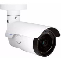
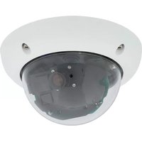
- More Camera For Less. Guaranteed!
- Innovations - Made in Germany
- THE MOBOTIX INFORMATION CHANNELS
- MOBOTIX Seminars
- Copyright Information
- CONTENTS
- Product Overview 10
- M25M Allround 10
- M25M with Special Lens Hemispheric L12 20
- Technical Specifications 32
- Delivered Parts and Dimensions 38
- Available Accessories 44
- MOBOTIX Software 49
- Installation 54
- Preparing the Installation 54
- Mounting the Camera with Wall Mount 63
- Mounting the Camera with Ceiling Mount 67
- Mounting the Camera with Pole Mount (Accessory) 71
- Adjusting the Camera and Exchanging the Lens 76
- Replacing the MicroSD Card 78
- Network and Power Connection 80
- Operating the Camera 88
- Manual and Automatic Operation – Overview 88
- First Images and the Most Important Settings 92
- Virtual PTZ and Full Image Recording 106
- MicroSD Card Recording 117
- Manufacturer 135
- Legal Notes
- Safety Warnings
- Installation Instructions:
- FOREWORD
- PRODUCT OVERVIEW
- M25M Allround
- General Product Characteristics
- Model Variants
- Complete HiRes Video Solutions by MOBOTIX
- Extraordinary Picture Quality
- Megapixel Image Sensors (5MP)
- 5MP Image Format: 5 Times More Detail Than Full HD
- Low Light Conditions – No Problem
- MxLEO: Exposure Optimization and Reduced Image Noise
- Hemispheric Technology
- Robust and Maintenance-Free
- A Master of Adaptability
- High-Resolution Sees More and Costs Less
- Universal Application from Vacation Homes to Airports
- The Right Lens for Every Application
- MOBOTIX Standard Lenses Are Easily Exchanged
- Virtual PTZ (vPTZ) - Without Motor
- Simultaneous Corrected Live Image and Full Image Recording
- Internal DVR
- MxActivitySensor Video Motion Analysis: Secure Detection, Avoiding False Alarms
- M25M with Special Lens Hemispheric L12
- L12 Lens: High-Resolution 180° Panorama
- Optimizing the M25M Panorama Image
- 22/136
- M25M Camera Manual: Product Overview
- L12 Lens: Panorama Focus – One Camera, Three Views
- L12 Lens: Double Panorama for a Simultaneous View in Two Directions
- L12 Lens: Surround View (Quad View)
- L12 Lens: Full Image and Normal View
- L12 Lens: Factory Settings of the Standard Views for a Wall Installation
- Advantages and New Features
- Smooth HiRes Video Streams
- Conclusive Still Images
- Good Color Images Even in Low Light
- More Details When Zooming
- Black&White Image Sensor with 5 Megapixels
- IT Cameras: Maximum Image Size Is Now HD Instead of VGA
- MxActivitySensor
- Low Power Consumption in Accordance with PoE Standard (IEEE 802.3af)
- Decentralized Video System
- Green IP Video
- Low Power Consumption
- Robust
- Modern
- High Resolution
- Sustainable
- Forward-Looking
- Notes
- Technical Specifications
- Lens Options
- M25M with Standard Lenses and M14 Thread
- M25M with Hemispheric Lens L12 (Fisheye)
- M25M with CSVario Lens
- Delivered Parts and Dimensions
- Camera Housing and Connectors
- Connectors
- Note
- Note on fastening cables leading into the camera:
- Removing the Cable Retainer
- Caution
- Replacing the Cable Retainer
- Dimensions for Wall Installation
- Dimensions for Ceiling Installation
- Dimensions of Wall Mount
- Drilling Template Wall and Ceiling Mount
- Available Accessories
- Lens Cover with Glass Pane
- Pole Mount
- MiniUSB Cable to MiniUSB (Straight/Angled)
- MiniUSB Cable to MiniUSB (Angled/Angled)
- MiniUSB Cable to USB-A Socket
- Ethernet Patch Cable for Bayonet Catch
- NPA-PoE-Set
- MX-Overvoltage-Protection-Box
- MX-NPA-Box
- MX-GPS-Box
- MX-232-IO-Box
- ExtIO Expansion Module
- Mx2wire+ Media Converter
- Installing Interface Boxes Under a Varioflex Wall Mount
- Other Accessories
- MOBOTIX Software
- Integrated Camera Software (Firmware)
- MxControlCenter
- MxControlCenter – Professional Video Management
- MxEasy
- MxEasy – Simple Operation of the Most Important Camera Functions
- MOBOTIX App
- MOBOTIX App - Mobile Remote Station for MOBOTIX Cameras and Door Stations
- INSTALLATION
- Preparing the Installation
- Mounting Options: Wall, Ceiling, Pole
- Wall-mounted
- Ceiling-mounted
- Mounting to a Wall
- Mounting to a Ceiling
- Mounting the Camera with Pole Mount
- Mounting with Hemispheric Lens L12
- High-Resolution Panorama Images
- Allround View
- Network Connection and Power Supply, UPS
- Power Over Ethernet (PoE Conforming to IEEE 802.3af)
- Advantages of PoE power supply:
- Using Uninterruptible Power Supplies (UPS)
- Preparing the Camera Connections, MX-Overvoltage-Protection-Box
- Wiring, Fire Prevention, Lightning and Surge Protection
- Guidelines for Wiring
- Fire Prevention
- Lightning and Surge Protection
- Mounting the Camera with Wall Mount
- VarioFlex Wall Mount
- 64/136
- M25M Camera Manual: Installation
- Procedure
- Mounting the Camera with Ceiling Mount
- VarioFlex Ceiling Mount
- 68/136
- Mounting the Camera with Pole Mount (Accessory)
- Pole Mount (MX-MH-SecureFlex-ESWS)
- Scope of Delivery and Required Parts
- Adjusting the Camera and Exchanging the Lens
- Adjusting the Camera
- Correcting the Image Horizon (for L12 Lens Only)
- Exchanging the Lens
- Proceed as follows to change a lens:
- Replacing the MicroSD Card
- Removing the MicroSD Card
- Inserting the MicroSD Card
- Network and Power Connection
- Notes on Cable Lengths and Power Supply
- Network Cabling For M25M With Patch Cables
- Connecting the Patch Cable to an MX-Overvoltage-Protection-Box, an MX-NPA-Box or a Standard Network Outlet
- Power Supply Using a Switch
- 82/136
- Power Supply When Connected Directly to a Computer
- Power Supply with Power-Over-Ethernet Products
- Connecting a USB Cable
- Connecting a Two-Wire MxBus Cable
- Variable PoE
- Camera Startup Sequence
- Manual and Automatic Operation – Overview
- Manually Using a Computer in the 10.x.x.x IP Address Range
- Advantages
- Disadvantages
- Automatically Using MxControlCenter or MxEasy
- Requirement
- Automatically Using DHCP
- First Images and the Most Important Settings
- Manually Setting Up the Network Parameters in a Browser
- Change the network parameters of your computer:
- Windows (XP, Vista and 7):
- Linux/Unix:
- Mac OS X:
- Set Up the Target Network Parameters of the MOBOTIX Camera:
- First Images and the Most Important Settings in the Browser
- Default access data for the administration menu
- Camera Views: Live, Player, MultiView
- First Images and Network Parameter Configuration in MxControlCenter
- Installation
- MOBOTIX- Searching and Displaying MOBOTIX Cameras
- Cameras Are Found But Are Located in a Different Subnet
- Reconfiguring Cameras in a Different Subnet
- Defining Additional Video Sources
- Editing the Video Source List
- Creating a New Layout
- First Images and Network Parameter Configuration in MxEasy
- Installing and Starting MxEasy
- Finding Cameras
- Reconfiguring Network Addresses of Cameras
- Integrating and Displaying Cameras
- Starting the Camera with the Factory IP Address
- Starting the Camera with an Automatic IP Address (DHCP)
- Virtual PTZ and Full Image Recording
- Preparing the Virtual PTZ Function
- Operation Using The Mouse And Scroll Wheel
- Operation Using USB Joystick
- Full Image Recording
- Activate/Deactivate Full Image Recording in the Browser
- Special M25M Configuration in the Browser
- Configuration of the M25M Basic Parameters
- 112/136
- M25M Camera Manual: Operating the Camera
- Ceiling-Mounted: Set North (User-Defined North Direction)
- MicroSD Card Recording
- Introduction
- Number of Write/Delete Cycles Per Flash Storage Cell
- Conservative Memory Usage Thanks to MOBOTIX MxFFS File System
- Storage Requirements and Life Expectancy of MicroSD Cards
- Monitoring The Cell Wear Of Flash Storage Devices (Patent Pending)
- Formatting the MicroSD Card
- Activating MicroSD Card Recording
- Activating the Recording
- Encryption and Authentication
- Accessing Data on the MicroSD Card
- Deactivating Card Recording
- Using a MicroSD Card in a Different MOBOTIX Camera
- Limitations on Warranty When Using Flash Storage Media
- Configuration in the Browser
- Overview
- Basic Settings
- General Browser Settings
- Additional Notes
- Protecting the Camera Against Condensation
- Password for the Admin Menu
- Permanently Deactivating the Microphone
- Starting the Camera with the Factory IP Address
- Resetting the Camera to Factory Settings
- Activating Event Control and Motion Detection
- Deactivating Text and Logo Options
- Deactivating the Camera Reboot
- Browser
- Cleaning the Camera and Lens
- Cleaning the Lens Cover:
- Legal Notes
- Safety Warnings
- Online Help in the Browser
- Declaration of Conformity
- Disposal
- Disclaimer
- Manufacturer
Brand : Mobotix
Model : M25M
Category : Security Camera