BlueW PowerWalker Remote Panel - Remote control BlueWalker - Free user manual and instructions
Find the device manual for free BlueW PowerWalker Remote Panel BlueWalker in PDF.

| Product Type | Remote Control |
| Brand | BlueWalker |
| Model | BlueW PowerWalker Remote Panel |
| Dimensions | 150 x 50 x 20 mm |
| Weight | 0.2 kg |
| Power Source | 2 x AAA batteries (not included) |
| Battery Life | Up to 1 year under normal use |
| Wireless Range | Up to 30 meters (line of sight) |
| Frequency | 433 MHz RF |
| Compatible Devices | BlueWalker UPS systems with remote panel support |
| Main Functions | Power on/off, emergency shutdown, status monitoring |
| Indicator Lights | LED for power and communication status |
| Operating Temperature | 0°C to 40°C |
| Storage Temperature | -20°C to 60°C |
| Humidity | 0% to 95% non-condensing |
| Housing Material | ABS plastic |
| Certification | CE, RoHS |
| Maintenance | Clean with a dry, soft cloth. Avoid liquids. |
| Safety Precautions | Do not expose to moisture or direct sunlight. Keep away from children. |
| Spare Parts | Replacement batteries (AAA) |
| Repairability | Non-repairable; dispose of according to local regulations. |
| Included Accessories | Remote panel unit, user manual, mounting bracket (if applicable) |
| Warranty | 1 year manufacturer warranty |
Frequently Asked Questions - BlueW PowerWalker Remote Panel BlueWalker
User questions about BlueW PowerWalker Remote Panel BlueWalker
0 question about this device. Answer the ones you know or ask your own.
Ask a new question about this device
Download the instructions for your Remote control in PDF format for free! Find your manual BlueW PowerWalker Remote Panel - BlueWalker and take your electronic device back in hand. On this page are published all the documents necessary for the use of your device. BlueW PowerWalker Remote Panel by BlueWalker.
USER MANUAL BlueW PowerWalker Remote Panel BlueWalker
4.3 EPO Operation 1 1
1. Introduction
The Remote Panel is a connectivity device that allows you to remotely monitor the status of the UPS.
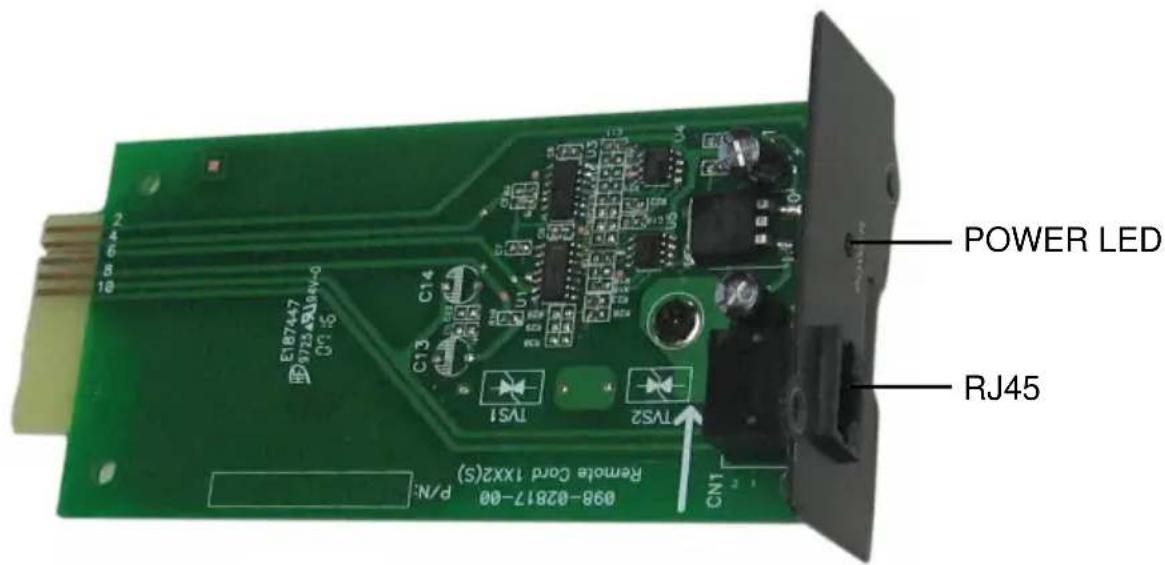
The Remote Panel include three parts:
text_image
POWER LED RJ45 098-02817-00 Remote Cord 1XX2(S) P/N: CN1 TS1 TS2 CN3 CN4 E187447 99723.ABJ45-0 098-02817-00 Remote Cord 1XX2(S)Remote Card
natural_image
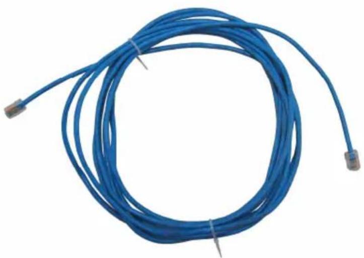
Blue cable with connectors, no visible text or symbolsCATEGORY 4 or 5 Network Cable
(Length≤400m, DC Resistance≤9.38Ω/100m)
text_image
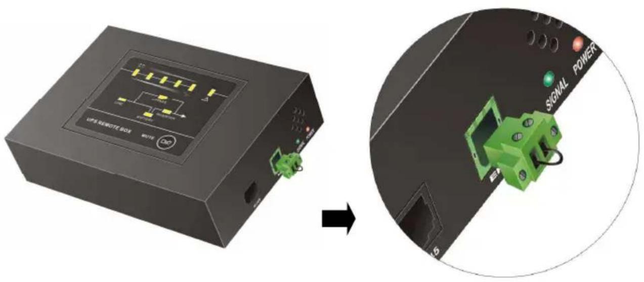
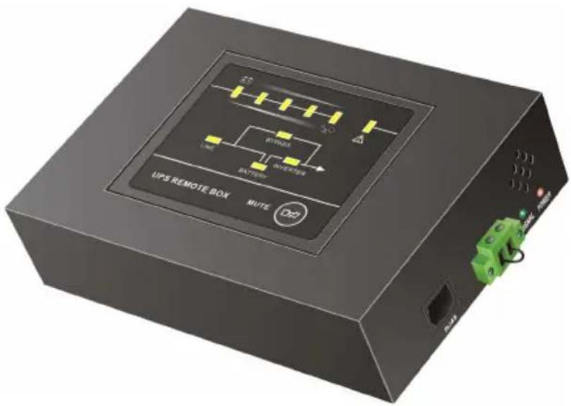
UPS REMOTE BOX MUTE D2Panel Interface LED Version
text_image
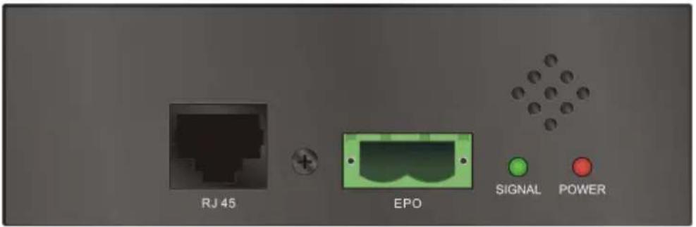
RJ 45 EPO SIGNAL POWERSide view
Power LED: Red LED, when the Power LED is turned on, it shows the power of the remote panel is OK.
Signal LED: Green LED, when the Signal LED is flashing, it shows the communication between the UPS and the remote panel is OK, and if the LED is turned on constantly, it shows that the communication is failed.
EPO: In emergency case, If the EPO connector be pulled out, UPS will cut off the output emergency. the short-circuit between the two pin of the EPO connector is cleared or the EPO connector on right side of the Panel Interface is pulled out directly, EPO function is active and the UPS will cut off the output
RJ45: Connect the straight-through CATEGORY 4 or 5 network cable from the Remote Card.
2. Features
The Remote Panel has the following features:
• Real-time monitoring the UPS conditions.
- Can be located away from the UPS with a straight-through CATEGORY 4 or 5 network cable up to 400m.
- Deactivate acoustic alarm.
- EPO (Emergency Power Off) function.
- Hot-swappable function.
- Quick and easy installation and operation.
3. Installation
Please follow the following steps to install the Remote Panel to the UPS:
- Insert the Remote Card into the intelligent slot of the UPS.
- Lock the screws of the Remote Card bracket.
-
Connect the straight-through CATEGORY 4 or 5 network cable from the Remote Card's RJ45 connector to the Panel Interface.
-
The status of the UPS will be automatically displayed on the Panel Interface.

text_image
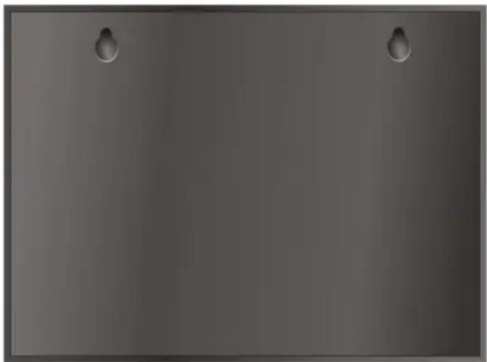
PANEL INTERFACE CABLE RJ48 POWER REMOTE CARD UPS- If you want hang the Panel Interface to the wall, please fix two nails with width 9 cm on the wall. Since there are two holes on the backside for holding the nails, then you can fix the panel to nails to keep them stable on the wall.
natural_image
Plain gray surface with two small metallic clips at the top (no text or symbols)Back view
4. Panel information and operation
4.1 Panel information
4.1.1 LED Display Panel
text_image
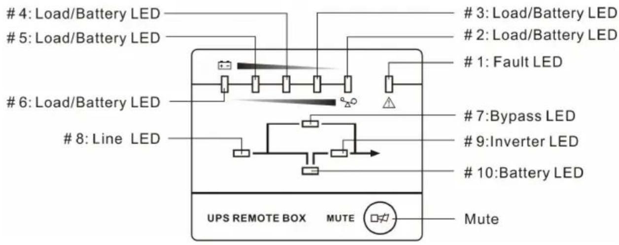
4: Load/Battery LED
5: Load/Battery LED
6: Load/Battery LED
8: Line LED
3: Load/Battery LED
2: Load/Battery LED
1: Fault LED
7: Bypass LED
9: Inverter LED
10: Battery LED
UPS REMOTE BOX MUTE Mute- Mute: Short - press(>0.5s, <4.5s) to mute or activate. The buzzer; Long-press(>5s) in line mode turn into battery test mode.
- Bypass LED: Orange LED, whenever the Bypass LED is turned on constantly, it shows that the load current is supplied directly from the utility power.
- Line LED: Green LED, it shows the utility power status. If LINE LED blinks, the mains power supply is out of tolerance.
- Inverter LED: Green LED, whenever the Inverter LED is turned on constantly, it shows that the load current is supplied from utility power or battery via the inverter.
- Battery LED: Orange LED, it shows the UPS is on battery mode or shows the battery status.
- Fault LED: Red LED, whenever the Fault LED is turned on, it shows that the UPS is in abnormal condition.
- #2\~#6 LEDs: The #2 LED is orange and the #3\~#6 LEDs are green, these LEDs indicate the percentage of the load level in Line mode and Bypass mode, or the battery capacity in Battery mode.
4.1.2 The Corresponding Form of the LED Display
Table 1. The corresponding form of the Panel Interface.
| No. | Status | LED display | Alarm | ||||||||||||
| #1 | #2 | #3 | #4 | #5 | #6 | #7 | #8 | #9 | #10 | ||||||
| 1 | Line Mode | 0~35% Load | ● | ● | ● | None | |||||||||
| 2 | 35%~55% Load | ● | ● | ● | ● | None | |||||||||
| 3 | 55%~75% Load | ● | ● | ● | ● | ● | None | ||||||||
| 4 | 75%~95% Load | ● | ● | ● | ● | ● | ● | None | |||||||
| 5 | 95%~105% Load | ● | ● | ● | ● | ● | ● | ● | None | ||||||
| 6 | Battery Mode | 0~20% Battery capacity | ● | ● | ★ | Beep once every sec, ◆ | |||||||||
| 7 | 20%~40% Battery capacity | ● | ● | ● | ● | Beep once every 4 sec, ◇ | |||||||||
| 8 | 40%~60% Battery capacity | ● | ● | ● | ● | Beep once every 4 sec, ◇ | |||||||||
| 9 | 60%~80% Battery capacity | ● | ● | ● | ● | ● | Beep once every 4 sec, ◇ | ||||||||
| 10 | 80%~100% Battery capacity | ● | ● | ● | ● | ● | ● | Beep once every 4 sec, ◇ | |||||||
| 11 | Bypass mode ↑ | ↑ | ↑ | ↑ | ↑ | ● | ● | ● | Beep once every 2 min, ◇ | ||||||
| 12 | Overloaded in Line mode | ● | ● | ● | ● | ● | ● | ● | ● | Beep once every sec, ◆ | |||||
| 13 | Overloaded in Bypass mode | ● | ● | ● | ● | ● | ● | ● | ● | ● | Beep once every sec, ◆ | ||||
| 14 | Overloaded in Battery mode, Early-warning | ● | ↑ | ↑ | ↑↑ | ↑↑ | ↑↑ | ↑ | ↑ | ↑ | ● | ● | Beep once every sec, ◆ | ||
| 15 | Overloaded Fault, Cut off the output | ● | ● | ↑ | ↑ | Continuously beep, ◇ | |||||||||
| 16 | Utility power abnormal | ↑ | ↑ | ↑↑ | ↑↑ | ↑↑ | ↑↑ | ↑↑ | ↑↑ | ★ | ↑ | ↑↑ | ↑, ◇ | ||
| 17 | Over temperature | ● | ● | ↑ | ↑↑ | Continuously beep, ◇ | |||||||||
| 18 | Inverter abnormal | ● | ● | ↑ | ↑↑ | Continuously beep, ◇ | |||||||||
| 19 | Output short circuited | ● | ● | ● | ↑ | ↑ | Continuously beep, ◇ | ||||||||
| 20 | BUS voltage abnormal | ● | ● | ↑ | ↑ | ↑↑ | Continuously beep, ◇ | ||||||||
| 21 | Charger or battery failed | ● | ↑ | ↑ | ↑↑ | ↑↑ | ↑↑ | ★ | Beep once every sec, ◇ | ||||||
| 22 | BAT SCR failed | ● | ● | ● | ↑ | ↑↑ | Continuously beep,◇ | |||||
| 23 | Fan abnormal | ● | ● | ● | ↑ | ↑↑ | ↑↑ | ↑↑ | Beep once every sec,◇ | |||
| 24 | INV RLY failed | ● | ● | ● | ↑ | ↑↑ | Continuously beep,◇ | |||||
| 25 | Inner Communication abnormal | ● | ● | ● | ↑ | ↑↑ | Continuously beep,◇ | |||||
| 26 | Parallel abnormal | ● | ● | ● | ● | ↑ | ↑↑ | Continuously beep,◇ | ||||
| 27 | Communication failed between the UPS and the Remote Panel | ★ | ★ | ★ | ★ | ★ | ★ | ★ | ★ | ★ | ★ | Continuously beep,◇ |
| 28 | EPO function Active | ● | ★ | ★ | ★ | ★ | Beep once every sec,◇ | |||||
| 29 | Negative power fault | ● | ● | ● | ● | ↑ | ↑↑ | Continuously beep,◇ | ||||
| 30 | Eeprom Write Fail | ● | ● | ● | ● | ↑ | ↑↑ | ↑↑ | ↑↑ | Beep once every sec,◇ |
• : LED ON Constantly
★ : LED Flash
↑ : LED display and alarm are dependent on other conditions.
◇ : Alarm can be muted by pressing Mute button.
◆ : Alarm can't be muted by pressing Mute button.
4.3 EPO Operation
EPO Trigger:
In emergency case, The UPS can be power off by activation of the EPO function by clearing the shortcircuit between the two pin of the EPO connector or pulling out the EPO connector on right side of the Panel Interface directly, when the EPO function is active, the Panel Interface will display as show in table 1 (NO.28).
EPO Cancel:
First of all, Recover shortcircuit wire between the two pin of the EPO connector then press the OFF button on the UPS panel (not the remote panel) to cancel the EPO status