
27209 - Remote control HUNTER - Free user manual and instructions
Find the device manual for free 27209 HUNTER in PDF.


| Product Type | Remote Control |
| Brand | Hunter |
| Model | 27209 |
| Dimensions (approx.) | 5.5 x 2.0 x 0.8 in (14 x 5 x 2 cm) |
| Weight (approx.) | 3.5 oz (100 g) |
| Power Source | 2 AAA batteries (not included) |
| Frequency | 433 MHz (typical) |
| Range | Up to 50 ft (15 m) |
| Compatible Devices | Hunter ceiling fans with remote control receiver |
| Main Functions | Fan on/off, speed control (low, medium, high), light on/off & dimming, reverse function |
| Number of Buttons | 6-8 typical |
| Indicator Light | LED transmission indicator |
| Mounting | Handheld or wall-mounted using bracket (if included) |
| Cleaning & Maintenance | Wipe with a dry, soft cloth; do not use liquids or abrasives |
| Safety | Keep away from water and extreme temperatures; use only in dry indoor environments |
| Battery Replacement | Replace when range decreases or LED dims; use fresh alkaline batteries |
| Spare Parts Availability | Batteries accessible; replacement remote available through Hunter customer service |
| Repairability | Non-repairable; replace entire unit if malfunctioning |
| Environment | Indoor use only; operating temperature 32-104°F (0-40°C) |
| Certifications | FCC, CE (typical) |
| Warranty | Limited 1-year warranty from date of purchase |
Frequently Asked Questions - 27209 HUNTER
User questions about 27209 HUNTER
0 question about this device. Answer the ones you know or ask your own.
Ask a new question about this device
Download the instructions for your Remote control in PDF format for free! Find your manual 27209 - HUNTER and take your electronic device back in hand. On this page are published all the documents necessary for the use of your device. 27209 by HUNTER.
USER MANUAL 27209 HUNTER
natural_image
Close-up of a silver electric fan with control knobs and a brand logo (no readable text or symbols)Form# 44092-01
20101215
©2010 Hunter Fan Co.
Universal Fan and Light Remote Control
Hand-Held Remote and Wall Cradle
Owner's Guide and
Installation Manual
SINCE 1886 Hunter®
1 · Welcome
Table of Contents
1 • Welcome ...... 2
2 • Installation Preparation .... 3
3 • Receiver Installation .... 4
4 • Transmitter Installation .....7
5 • Programming the Remote .....8
6 · Operation ....8
7 • Troubleshooting .... 10
8 • Warranty 11
© 2010 Hunter Fan Company
Read and Save these Instructions
Caution: Risk of Electrical Shock!
All wiring must be performed in accordance with national and local electrical codes. If you are unfamiliar with the wiring codes, you should use a qualified electrician.
To avoid overheating and possible damage to other equipment, do not install to control a receptacle, motor operated appliance, or transformer-supplied appliance. Use only to control one ceiling fan with or without a light fixture.
Ratings: 120 VAC, 60 Hz, 1.0 Amp Fan Receiver Weight: 6 oz. 300 Watts incandescent light
2 • Installation Preparation
Notes:
- This device complies with Part 15 of the FCC Rules. Operation is subject to the following two conditions: (1) this device may not cause harmful interference, and (2) this device must accept any interference received, including interference that may cause undesired operation.
- This equipment has been tested and found to comply with the limits for a Class B digital device, pursuant to Part 15 of the FCC Rules. These limits are designed to provide reasonable protection against harmful interference in a residential installation. This equipment generates, uses and can radiate radio frequency energy and, if not installed and used in accordance with the instructions, may cause harmful interference to radio communications. However, there is no guarantee that interference will not occur in a particular installation. If this equipment does cause harmful interference to radio or television reception, which can be determined by turning the equipment off and on, the user is encouraged to try to correct the interference by one or more of the following measures:
- Reorient or relocate the receiving antenna.
- Increase the separation between the equipment and receiver.
- Connect the equipment into an outlet on a circuit different from the one the receiver is connected to.
- Consult the dealer or an experienced radio/TV technician for help.
- For use only with electrically reversible ceiling fans rated at 1.0 amp or less,
and fan incandescent light kits rated at 300 watts or less.
- Not for use with shaded-pole motors, Hunter 42" Low Profile fans, and Hunter Baseball fans. Not recommended for use with the Hunter Original®. For Hunter Original® series fans, use Hunter control model numbers 27187, 22691, or 27189.
- Medium and Low fan speeds are determined by the control and thus may vary from the factory settings due to normal motor variations.
- For use with Hunter Hanging Systems (excludes Hunter Original) on flat ceilings or angled ceilings with a pitch up to 34°.
- Not for use in applications where the fan does not have a wall switch.
Any changes or modifications to this equipment not expressly approved by Hunter Fan Company will void the user's authority to operate the equipment.
BEFORE YOU INSTALL THIS CONTROL: USE THE PULL CHAIN SWITCH TO SET THE FAN SPEED TO THE HIGH POSITION BEFORE INSTALLATION. DO NOT USE THE PULL CHAIN TO CHANGE THE FAN SPEED AFTER INSTALLATION, AS DAMAGE TO YOUR FAN OR REMOTE MAY RESULT. THE SPEED OF THE FAN SHOULD ONLY BE CHANGED BY THE HUNTER CONTROL!!
3 · Receiver Installation
BEFORE INSTALLING THE CONTROL:
- USE THE PULL CHAIN SWITCH TO SET THE FAN SPEED TO THE HIGH POSITION BEFORE INSTALLATION. DO NOT USE THE PULL CHAIN TO CHANGE THE FAN SPEED AFTER INSTALLATION, AS DAMAGE TO YOUR CEILING FAN OR UNIVERSAL CONTROL MAY RESULT THE SPEED OF THE FAN SHOULD ONLY BE CHANGED BY THE HUNTER CONTROL!!
- Set the ceiling fan light kit to the ON position before installation.
Installation Instructions:
- Install the ceiling fan according to its instructions, up to the point of making the electrical connections. Connect receiver to ceiling fan according to the mounting types shown on the next page. Determine your ceiling fan mounting type from the images on Pages 4-5. Most installations will be one of these five types.
- If the fan is already installed, turn the power OFF at the main electrical panel. Reverse the installation procedure according to the fan instructions, to the point of disconnecting the fan wiring. Connect the receiver to the ceiling fan according to the mounting type as shown on Pages 4-5.
IMPORTANT! If your ceiling fan light kit is using incandescent bulbs, then slide the CFL / INC switch to the INC position. (Fig. 2) If your ceiling fan light kit is using compact fluorescent light bulbs (CFL), then slide the CFL / INC switch to the CFL position. NOTE: When the switch is in the CFL position, the dimming feature is disabled, and you will not be able to dim the light bulbs. This feature is to protect both your bulbs and your receiver as CFL bulbs are not able to dim and will malfunction if dimming is attempted.
Low Profile Style I (Figure 1): Secure receiver to the fan plate above the motor with UL-listed cable ties (not included).
Connect wiring as shown in Figure 6. Extend antenna through one of the ceiling plate openings (approximately 3–6").
NOTE: Some fans may have considerable excess lead wire. For easier canopy installation, cut the excess wire leaving a minimum of 6 inches remaining. Restrip the fan lead wires 1/2 inch. Place remaining excess wire into the ceiling electrical box as needed.

natural_image
Simple line drawing of a rectangular device with a curved arrow indicating rotation or movement (no text or symbols)
natural_image
Mechanical component diagram labeled Figure 1, showing a cylindrical assembly with internal components and wiring (no readable text or symbols)
Cable Tie Routing for Low Profile Fans (Figs.1 & 3): Insert cable tie through openings as shown. DO NOT insert the cable tie through the inside of the receiver. The cable tie can be placed across the length or width of the receiver to best match your fan installation type.
3 · Receiver Installation

Low Profile Style II (Figure 3): Secure receiver to the ceiling mounting bracket with UL-listed cable ties (not included). Connect wiring as shown in Figure 6. Extend antenna above the ceiling mounting bracket (approximately 3–6").
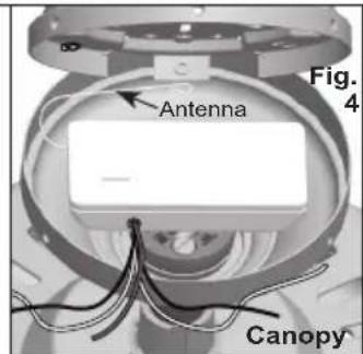
Canopy Hanger (Fig. 4): Place receiver in canopy. Connect wiring as shown in Figure 6. Extend antenna through one of the ceiling plate openings (approximately 3–6").

Hunter Hands-Free™ Canopy: Connect wiring as shown in Figure 6. Place receiver inside mounting bracket. Extend antenna above the ceiling mounting bracket (approximately 3–6").
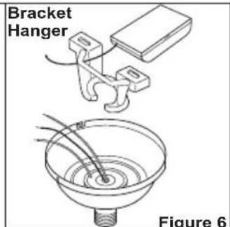
Bracket Hanger: Starting with the antenna wire, slide receiver inside mounting bracket. If a ground wire mounting screw prevents the receiver from sliding into the bracket, move ground wire and screw to an unused hole at the top of the bracket or secure with a canopy mounting screw. The bracket must remain properly grounded. Connect wiring as shown in Figure 6. Extend antenna above the receiver (approximately 3 - 6").
NOTE: Some fans may have considerable excess lead wire. For easier canopy installation, cut the excess wire leaving a minimum of 6 inches remaining. Restrip the fan lead wires 1/2 inch. Place remaining excess wire into the ceiling electrical box as needed.
3 · Receiver Installation
- Use the 2 large (orange) wire connectors supplied to connect the receiver and house wiring, then use the 3 small (blue) wire connectors supplied to connect the receiver and ceiling fan wiring. Refer to the Wiring Diagram in Figure 6.
If you are installing the remote with a Hunter Fan, the wire colors in the fan will be as follows:
Light Power = Black with a White Stripe
Fan Power = Black
Common = White
*These are only the Hunter fan wire colors. Other brands may use different colors.
-
Be sure the antenna is positioned securely, so it does not interfere with the ceiling fan motor. Do not modify or damage the antenna wire, as control performance may be reduced. After securing the receiver, antenna, and wiring, finish hanging the ceiling fan according to its instructions.
-
Restore power at main electrical panel.

*Hunter fan wire colors. Other brands may use different colors.
4 • Transmitter Installation
- Install the included 12-Volt alkaline battery (A23 or equivalent) inside the handheld transmitter.
- Mount the remote holder over the ceiling fan's wall switch using the existing wall plate screws. Refer to Figure 8.
- The transmitter can be placed on the remote holder for convenience or safekeeping.

natural_image
3D CAD model of a remote control device showing external components and internal structure (no text or symbols)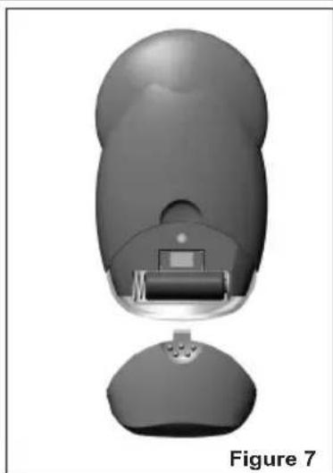
natural_image
3D rendered model of a computer mouse with a visible internal component, labeled as Figure 7 (no text or symbols on the object itself)5 · Programming the Remote
Programming the Remote:
The remote transmitter and remote receiver should already be programmed to work together.
- If you want the remote to control a second fan, or you want to re-progam remote:
- Turn the power to the second fan (or the fan you want to re-program) OFF at the wall switch. Then, turn it back ON.
- Within 30 seconds, press the 1 (Fan Low) and 3 (Fan High) buttons on the transmitter together and hold them down for 5 seconds. The LED light on the transmitter will blink 3 times to confirm.
- The fan's light will turn OFF and the fan will turn ON at low speed to further confirm the programming has taken effect.
- Repeat this process to correct interference with other devices, or to program additional fans to this remote.
- If there is any fan in your home you do NOT want programmed to this remote, make sure the power to that fan is turned OFF at its wall switch while programming the remote.
Fan Operation:
For best fan operation: Start the fan on High (3), and then select the desired speed.
- Press the High (3), Medium (2), or Low (1) speed buttons to turn the ceiling fan ON at the desired speed.
- Press the fan "0" key to turn the ceiling fan OFF.

6 · Operation
Light Operation:
- Turn ON wall switch. The light will turn ON at maximum brightness.
- Press and quickly release either light button on the hand held remote to turn the light OFF or ON.
- After a power outage, the light will turn ON when power is restored. Press and quickly release one of the light buttons once to turn the light back OFF after a power outage.
-
Press and hold either light button for more than 1 second to activate the dimming cycle.
-
Press to turn the light ON at the maximum level and continue holding down to dim the light.
- Press to turn the light ON at a low level and continue holding down to brighten the light.
- Continue to hold the light button to repeat the cycle.
- Release the light button when the desired light level is reached.
To turn the light OFF:
- Press both of the light buttons & together to begin "Safe Exit Mode." The LED light on the transmitter will blink 4 times to let you know it's starting to turn the light off. The light will slowly dim down until it's completely off within 30 seconds. This "Safe Exit" feature provides you with enough light to leave the room safely.
- To turn the light off instantly, press and quickly release either light button or once.
- When the light is turned on again, it will "remember" the brightness level it was at before it was turned off and resume at that level again.

7 · Troubleshooting
| Symptom Possible Causes Solution1.No functions operate. Main Power not restored. Replace fuse. Turn ON circuit breaker. Turn ON wall switch.Fan pull chain not set to High. Set fan pull chain to High speed.Light pull chain not set to ON. Set light kit to ON.Receiver wiring incorrect. Verify wiring connections.Transmitter not programmed to Re-program the remote. Refer to “Programming the Remote,” Page 8. receiver in fan.Battery too weak. Replace with new, 12-Volt alkaline battery. Refer to “Transmitter Installation”, Section 5. | |
| 2.Fan clicks when remote buttons pushed, but blades do not move. | Fan pull chain not set to High. Set fan pull chain to High speed. |
| 3.Fan clicks when remote buttons pushed, but light does not work. | Light pull chain not set to ON. Pull light chain to turn ON. |
| 4.Operates only at close range. Signal blocked from reaching receiver.Battery too weak. Replace with new, 12-Volt alkaline battery. Refer to “Transmitter Installation”, Section 5.Interference Re-program the remote to a different frequency by pressing and holding fan speedbuttons 1 & 3 together for 5 seconds. Light on transmitter will blink 3 times. Light will come on and fan will turn on at low speed to confirm programming is complete. | |
| 5.Inconsistent operation. Signal partially blocked from reaching receiver.RF interference. Turn OFF wall switch for 5 seconds, then turn back ON.Continuing RF interference. Re-program the remote. Refer to “Programming the Remote,” Page 8. | Extend antenna into ceiling box, or move it for better reception. |
8 · Warranty
HUNTER FAN COMPANY CONTROL LIMITED WARRANTY
The Hunter Fan Company makes the following limited warranty to the original purchaser of the Control ("Control"): Your Control is warranted to be free from defects in material and workmanship for a period of one year from the date of sale. If the Control malfunctions or fails within the warranty period due to a defect in material or workmanship we will replace it free of charge. IF THE ORIGINAL PURCHASER CEASES TO OWN THE CONTROL, THIS WARRANTY AND ANY IMPLIED WARRANTY, INCLUDING BUT NOT LIMITED TO ANY IMPLIED WARRANTY OF MERCHANTABILITY OR FITNESS FOR A PARTICULAR PURPOSE, ARE VOIDED. THIS WARRANTY IS IN LIEU OF ALL OTHER EXPRESS WARRANTIES. THE DURATION OF ANY IMPLIED WARRANTY, INCLUDING, BUT NOT LIMITED TO, ANY IMPLIED WARRANTY OF MERCHANTABILITY OR FITNESS FOR A PARTICULAR PURPOSE, IN RESPECT TO ANY CONTROL, IS EXPRESSLY LIMITED TO THE PERIOD OF THE EXPRESS WARRANTY SET FORTH ABOVE FOR SUCH CONTROL. This warranty excludes malfunctions or failures which were caused by repairs by persons not authorized by us, mishandling, improper installation, modifications, or damage to the Control while in your possession, or unreasonable use. This warranty does not apply to batteries or to deterioration or damage to the product caused by the use of faulty batteries. To obtain a replacement, return your Control postage prepaid along with proof of purchase to Hunter Fan Company Service Department at 7130 Goodlett Farms Pkwy. #400, Memphis, Tennessee 38016. IN NO EVENT SHALL HUNTER FAN COMPANY BE LIABLE FOR CONSEQUENTIAL OR INCIDENTAL DAMAGES. SOME STATES DO NOT ALLOW LIMITATIONS ON HOW
LONG AN IMPLIED WARRANTY LASTS OR THE EXCLUSION OR LIMITATIONS OF INCIDENTAL OR CONSEQUENTIAL DAMAGES SO THE ABOVE LIMITATIONS OR EXCLUSIONS MAY NOT APPLY TO YOU. THIS WARRANTY GIVES YOU SPECIFIC LEGAL RIGHTS AND YOU MAY ALSO HAVE OTHER RIGHTS WHICH VARY FROM STATE TO STATE.
If you need parts or service assistance, please call 888-830-1326 or visit us at our Web site at http://www.hunterfan.com. Hunter Fan Company 7130 Goodlett Farms Parkway #400 Memphis, Tennessee 38016
- Universal Fan and Light Remote Control
- · Welcome
- Table of Contents
- Read and Save these Instructions
- Caution: Risk of Electrical Shock!
- • Installation Preparation
- Notes:
- · Receiver Installation
- BEFORE INSTALLING THE CONTROL:
- Installation Instructions:
- • Transmitter Installation
- · Programming the Remote
- Programming the Remote:
- Fan Operation:
- · Operation
- Light Operation:
- To turn the light OFF:
- · Troubleshooting
- · Warranty
- HUNTER FAN COMPANY CONTROL LIMITED WARRANTY
Brand : HUNTER
Model : 27209
Category : Remote control