
DV1670D - Dictaphone Clover Electronics - Free user manual and instructions
Find the device manual for free DV1670D Clover Electronics in PDF.


| Product Type | Digital Voice Recorder |
| Brand | Clover Electronics |
| Model | DV1670D |
| Dimensions | 4.33 x 1.18 x 0.51 inches (110 x 30 x 13 mm) |
| Weight | 2.12 oz (60 g) |
| Power Supply | Built-in rechargeable Li-ion battery, USB charging |
| Recording Medium | Built-in 4GB flash memory, expandable via microSD up to 32GB |
| Recording Format | WAV (PCM), MP3 |
| Sampling Rates | 8 kHz – 44.1 kHz |
| Recording Time | Up to 557 hours (LP mode) with 4GB |
| Playback | Built-in speaker, 3.5mm headphone jack |
| Interface | Micro USB 2.0 |
| Display | Monochrome LCD with backlight |
| Functions | Voice activation, timed recording, password protection, variable playback speed |
| Special Features | One-touch recording, low battery indicator, voice filter |
| Maintenance | Keep away from moisture; clean with dry cloth |
| Safety | Not suitable for children under 3 years |
| Included Accessories | USB cable, earphones, user manual (PDF) |
| Repairability | Not user-serviceable; contact Clover support |
Frequently Asked Questions - DV1670D Clover Electronics
User questions about DV1670D Clover Electronics
0 question about this device. Answer the ones you know or ask your own.
Ask a new question about this device
Download the instructions for your Dictaphone in PDF format for free! Find your manual DV1670D - Clover Electronics and take your electronic device back in hand. On this page are published all the documents necessary for the use of your device. DV1670D by Clover Electronics.
USER MANUAL DV1670D Clover Electronics
Stand-Alone 16Channel
Copyright © 2011 Clover Electronics U.S.A. All Rights Reserved.
System Users Manual
Version 1.1
Manual created in summer of 2011. This user manual contains instrucons for operaons for DVR Unit, Client Applicaon, Mobile Device Applicaon and other helpful ps.
Table of Contents
Contents
Table of Contents....3
Chapter 1. Preface .... 10
- About This Guide....10
- Precauons - Before You Start! 11
- Precauons – After Powering On! 13
- Precauons – Roune Maintenance! 14
- Contents of Items Included....15
Chapter 2. Hardware Descricon....17
- Technical Specicaon....17
- Rear Panel....19
- Rear Port Specicaon and Connecon Examples....21
Power input....21
VGA (Video Graphics Array) Port 21
Main Monitor Output 23
SPOT Monitor Output 23
Camera Input 24
RS-232 Serial Connector....24
Oponal Alarm Sensor Extension Box 26
10-Way Terminal Block 27
RS-485 Connecons 28
Alarm Out....29
Sensor Input 29
USB Connecon 32
Ethernet Port 32
-
Front Panel....36
-
Remote Controller....38
Chapter 3. Quick Setup .... 39
-
Placement 39
-
Connecon....39
- Quick Power On 41
- Inial Boot....42
- Setup Screen 43
- Change Password and Enable Auto Lock 44
7.Labeling Camera....48 - Enable Recording 49
- Prepare Network....51
Chapter 4. Main Menu (Root Menu)....53
- Main Items....53
- Sub operational items....54
Chapter 5. The "System" Root Menu Item .... 55
Convenon of Menu Tree....55
- The "System" Branch 56
- The "Record" Branch....58
- The "Network" Branch....59
- The "Camera" Branch....60
- The "Display" Branch 61
- The "Alarm" Branch 62
Chapter 6. The "Search" Root Menu Item....63
- The "Calendar" Search Branch....63
- The "Event" Search Branch....64
- The "Date / Time" Search Branch 65
Chapter 7. The "Backup" Root Menu Item....66
- Calendar, Quick and List Branch 66
Chapter 8. The "ER", "PTZ", and "Sound" Root Menu Items....67
Chapter 9. Systems Secon In-Depth ......68
- INFORMATION GUI 68
Language 68
Remocon ID (Remote Controller ID) 69
Mouse Sensitivity....71
Video Standard....71
MAC Address....72
Webcode....72
Versions....72
- DISK MANAGER GUI....73
Adding, installing HDD and other drives....73
Installing ODD (Opcal Disk Drive)....74
- DEFAULT SETTING GUI 79
Conguring Year/Month/Day 80
Conguring Date & Time....81
Conguring Daylight Saving Time 81
Conguring Time Server 82
-
UPGRADE GUI....83
-
CONFIGURATION GUI....84
Conguraon Download....84
Conguraon Upload....85
- PASSWORD GUI....86
Conguring User ID 86
Modifying User Informaon 87
Conguring User Authority 87
Conguring Network Covert 88
- BUTTON SETTING GUI....89
Conguraon of audible beep....89
Conguraon of Auto Key Lock 89
Conguraon of Emergency Lock....90
Chapter 10. Record Secon In-Depth....91
- Compression, Resoluon, Quality, and Speed of Video 91
Video Compression 91
Video Resoluon....91
Video Quality....92
Speed of Video 92
- Calculang Storage Required....94
4 Channel DVR Storage Reference Chart....95
9 Channel DVR Storage Reference Chart....96
16 Channel DVR Storage Reference Chart....97
- EVENT RECORDING GUI ....98
Conguring Pre Recording 98
Conguring Event Recording....98
- SCHEDULE RECORDING GUI....100
Chapter 11. Network Secon In-Depth....105
-
About Network Secon and Clients.... 105
-
IP ADDRESS GUI....106
DHCP (Dynamic Host Control Protocol)....106
Transmission Opon 108
Web Server Port....108
-
E-MAIL SETUP GUI....110
-
DDNS OPTION GUI 112
Built in DDNS Server setup....112
DDNSIP.Net example....113
-
EMAIL NOTIFICATION GUI....120
-
NETWORK FRAME GUI....121
Chapter 12. Camera Secon In-Depth....122
-
CAMERA SETTING GUI....122
-
PTZ SETTING GUI....123
Additional PTZ seng....124
-
CONTROLLER GUI....126
-
CAMERA TITLE GUI....127
-
PTZ TOURING GUI 128
-
SERIAL PORT SETTING GUI 129
-
How to operate PTZ camera .... 130
Chapter 13. Display Secon In-Depth....132
- OSD GUI....132
2.SPLIT / SEQUENCE GUI....134 - TV ADJUSTMENT 138
Chapter 14. Event Secon In-Depth ...... 139
- SENSOR GUI....139
- ALARM GUI....140
- MOTION DETECTION GUI....141
- SPOT OUT GUI....143
- INTERNAL BUZZER GUI....144
- EXTENDED GUI 145
Alarm Sensor extension box seng 146
Chapter 15. Search Operaon ....147
- Geng to Search Screen .... 147
- Calendar Search ....148
- Event Search....151
- Date and Time Search....153
- Playback Control Menu Bar 154
Playback Controls....154
Play and Pause operaon 155
Fast Play, Rewind Operaon....155
Mouse Only Operaon....157
De-Interlacing Opon....158
Quick Backup During Playback....159
Chapter 16. Backup Operaon....161
- Calendar Backup .... 161
- Backup Viewer .... 167
Chapter 17. Mobile and Remote Client Applicaons ....169
- iPhone 169
iPhone Applicaon Installaon....169
Adding a DVR To Your iPhones MPRMS Applicaon 169
Search from iPhone....174
Controlling Relay-Out from iPhone....177
PTZ control from iPhone 177
- Android Phone 179
Program Installaon for Android....179
Applicaon Execuon for Android....179
Register the product informaon for Android....180
Modify/Delete of Registered Informaon for Android....181
Remote conncon for Android 182
Live view on Android....183
Main menu view on Android 183
PTZ control for Android....184
PTZ Preset for Android....186
Search on Android....187
Relay Out for Android 188
Informaon display opon on Android 189
End the conneccon for Android....190
- Windows Mobile....191
Install the program to Windows Mobile....191
Execute the program for Windows Mobile....191
Register the Product Informaon on Windows Mobile....192
Connect / Disconnect on Windows Mobile 194
Search on Windows Mobile 196
PTZ Control for Windows Mobile....197
Remote Alarm Control for Windows Mobile 199
- Internet Explorer Version 7 and later ....200
Inial Connecon....200
Display Conguraon....202
Chapter 1. Preface
This manual contains user instrucon on how to operate the Digital Video Recording device (DVR Unit), Remote Controller, Client Applicaon, Mobile Applicaon and Central Monitoring Soware Applicaon.
This manual also contains cauons and nocaon regarding safe operang parameters to protect the equipment and equipment operator. Please read this manual and comply with its suggested guidelines for proper operaon of this equipment.
For any further concerns and queson please inform sellers for further informaon.
Please properly retain this copy of the manual for future reference.
1. About This Guide
This guide is comprised of Table of Contents where you will nd Chapters divided logically discussing about parcular topics. Then it is further divided by seconds that discuss more detailed discussion pertaining to certain features of Chapter topics.
This manual also includes Index secon where popular subjects or key concepts are referenced by page numbers where those topics are discussed.
What this manual is not discussing are topics about upgrades and repairing physical unit. These should be done through seller's authorized repair centers or by detailed direcon from seller. Upgrades and repairs consists of adding and removing Hard Disk Drive, adding and removing other media drive, upgrade or downgrade the Firmware, replace any electronic components inside physical units. These acons should be under the guidance of qualified technician because improper acons may cause permanent damages to the unit. Some drives also have compatibility constraints and they are constantly being updated as new products emerge from drive manufacturers.
2. Precauons - Before You Start!
Item 1. DVR Unit's power seng must be on POWER OFF posion before power adapter is plugged into the DVR Unit.
Press down on toggle buon towards boom.
This event will prevent electric spark and prevent possible re, electrocuon and product damages.
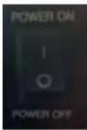
Item 2. DVR Unit's power setting must be on POWER OFF position before adding cameras, monitor, Hard Disk Drive and other electronic component to DVR Unit.
Cover of the DVR Unit must be closed while DVR Unit is powered on.
All other external devices should be introduced while DVR Unit is turned off.

Item 3. DVR Unit must have about 15 cenmeters (about 6 inches) clearance from the wall.
DVR Unit must have 5 cenmeters (about 2 inches) clearance for the side of the DVR Unit of any obstrucons.

Item 4. DVR Unit must be installed in none humid place.
Also do not place the DVR Unit near dusty area.
It is also advised that DVR Unit must be away from large power supplies such as power transformers, and also do not install this DVR Unit in closets that does not have temperature control.

natural_image
Cartoon illustration of a sad rectangular object with arms and legs, next to a smaller electronic device emitting smoke (no text or symbols)Even if DVR Unit may tolerate higher temperature Hard Disk Drives may yield to lower temperature tolerance compared to the DVR Unit.
It is advised that DVR Unit must be kept in standard room temperature whenever possible and any way not to exceed 50C (122F).
Item 5. Never upli the cover to perform an upgrade, aempt a hardware repair while DVR Unit is sll powered on.
Users should be aware that taking the cover of from the DVR Unit might void the warranty without consulting with seller.

natural_image
Illustration of a hand holding a book with a lightning bolt and starburst symbol (no text or symbols present)Improper upgrade may result on permanent equipment failure and user must consult with sellers and their skilled technicians before any upgrade.
Item 6. Keep the area clean around where DVR Units will be installed.
In case you need to clean the DVR Unit itself, please use dry cloth. DO NOT use any organic solvent. This will damage the DVR Unit and may cause electronics failure if solvent or fumes are exposed to the DVR Unit.

natural_image
Cartoon illustration of a sad rectangular object with a hand reaching toward it and a small cube with 'ALLI' written beside it (no text or symbols on the object itself)Item 7. Do not overload the circuit by having mulple devices on one power strip.
Avoid same power circuit input from hair dryer, coee makers, curling iron, refrigerator or other appliances that may draw concentrated power consumpon sporadically.
Uninterruptable power devices such as UPS power surge protectors are recommended and at least the DVR DVR Units must be connected properly approved power surge protector.

natural_image
Cartoon illustration of a sad rectangular object with angry expression and a tray of fruits (no text or symbols)Input voltage tolerance should be at least 10% of specied voltage level indicated o from included power adapters.
Failure to follow this guideline may cause equipment failure or possibly re or electrocuon.
3. Precauons – Aer Powering On!
Item 1. If you detect strange odor or detect strange raling noise immediately turn the DVR
Unit's power o .
Please contact your seller or service center for further instrucon.

natural_image
Cartoon illustration of a confused rectangular block with question mark above, surrounded by motion lines (no text or symbols)Item 2. Avoid shock and keep the DVR unit free from vibraon.
Constant vibraon and sudden shock will possible damage Hard Disk Drive and may cause bad sectors on Hard Disk Drive, dislodged connectors and may even cause damage to the main board.

natural_image
Cartoon illustration of a hand holding a rectangular object with a smiling face, emitting steam (no text or symbols)Item 3. Make sure any debris does not fall in through venlaon hole.
Also be cauous about other conducive material such as paper clips or other conducive material to have any contact with the main board of the DVR unit.

natural_image
Cartoon illustration of a hand crushing a damaged block with broken edges and debris (no text or symbols)4. Precauons – Roune Maintenance!
Item 1. Check to see if the LED (Light Eming Diode) is on.
If DVR unit does not have LED light on please check rst if power buon is on or o and make sure that it is at POWER ON posion.

natural_image
Cartoon illustration of a smiling rectangular object with a hand waving, labeled 'LED' (no text or symbols on the object itself)If you sill do not see LED light, then please check power adapter and outlet.
Item 2. Make sure that HDD Overwrite (Hard Disk Drive) is enabled.
If DVR unit does not have HDD Overwrite not enabled HDD will only write video information on un I HDD's capacity reaches maximum capacity.
This may result in latest recorded video informaon not being present in DVR unit.

natural_image
Cartoon illustration of a smiling rectangular character with arms and legs, giving a thumbs-up gesture (no text or symbols)Chapter 9, Secon 2. DISK MANAGER GUI on page 77 covers more details about seng HDD Overwrite opon.
Item 3. Hard Disk Drive is the only moving devices found on DVR unit. As with many moving devices users must pay special aenon to the wellness and opmal funconality of such devices. Your HDD is where video informaon is kept for future review.

natural_image
Cartoon illustration of a person using a computer with a large cylindrical device (no text or symbols present)In the DVR unit there are HDD S.M.A.R.T. features that monitor the wellness of HDD disk itself. The S.M.A.R.T displays the current hard drive condion and temperature of the hard disk drive. The S.M.A.R.T is abbreviated from Self-Monitoring, Analysis, and Reporng Technology, where hard disk manufacturers have implemented to warn possible failing condion of hard disk drive. It recommended that HDD with bad sectors, broken images when video images are played back, hear clicking noise, and DVR unit indicang that it is no longer recording video, then it may well be that there are defective HDD in DVR unit.
Please contact your seller or their authorized repair center for further instrucon.
Later in this manual Chapter 9 secon "S.M.A.R.T(Disk Management)" pages 78 will explain more about HDD S.M.A.R.T. features.
5. Contents of Items Included
natural_image
Front view of a rectangular electronic device with ports and indicator lights (no visible text or labels)DVR

Baery

Screw

Program CD

Adapter

Baery
cable

Remote
controller

natural_image
Abstract geometric diagram of a folded paper or envelope structure (no text or symbols)| Component | Descripon |
| DVR | Stand Alone Digital Video Recorder |
| Baery | 1.5V (AAA) 2 pcs. |
| Screw | For HDD moung |
| Program CD | Manual and Client program |
| Adapter | DC 12V 5A |
| Power cable | Power cable |
| Remote controller | For DVR operaon |
Chapter 1. Preface
5. Contents of Items Included
*If you are missing any components listed above please contact your seller for further instrucon.
Chapter 2. Hardware Descripon
1. Technical Specicaon
Operang System: Embedded Linux
Video Recording Compression: H.264
Video Transmission Compression: H.264
Supported Video Standards: NTSC / PAL
Video Output: Composite (main monitor output) via BNC
VGA monitor via VGA port
TV conneccon via S-Video
SPOT monitor via BNC
One to one video loop-out via BNC (equal number as camera input)
Audio Input: Single Mono RCA, 1Vpp, 10k ohm
Audio Output: Four Mono RCA, 1Vpp, 10k ohm
Audio Compression: G723.1
Sensor Input: Four sensor input ports via pluggable 10-way terminal block
Alarm Output: Single alarm output port via pluggable 10-way terminal block
Communicaon:
RS-485 Port – Single TX(+), single RX(-) via pluggable 10-way terminal block
RS-232 Port - 9 pole D-Type male connector
Ethernet Port – RJ-45 Type 10/100/1000 Base-T, DHCP, Stac IP and DDNS
Recording Resoluon:
NTSC - CIF(352X240), 2CIF(704X240), D1(704X480)
PAL-CIF(352X288), 2CIF(704X288), D1(704X576)
Recording Frame Speed per second:
4ch DVR - CIF resoluon 120 frames per second at NTSC (100 fps at PAL)
2CIF resoluon 120 frames per second at NTSC (100 fps at PAL)
D1 resoluon 120 frames per second at NTSC (100 fps at PAL)
9ch DVR - CIF resoluon 270 frames per second at NTSC (255 fps at PAL)
Chapter 2. Hardware Description
1. Technical Specification
2CIF resoluon 240 frames per second at NTSC (200 fps at PAL)
D1 resoluon 120 frames per second at NTSC (100 fps at PAL)
16ch DVR - CIF resoluon 480 frames per second at NTSC (400 fps at PAL)
2CIF resoluon 240 frames per second at NTSC (200 fps at PAL)
D1 resoluon 120 frames per second at NTSC (100 fps at PAL)
Recording Mode: Emergency, Schedule, Sensor, Moon, Sensor + Moon, Pre and Post Alarm Recording
Recording Search Method Type:
Calendar Search, Date and Time Search, Event List Search, First Search (Oldest recording not over written in HDD), Last Search (Newest recording in HDD)
Search Speed:
Forward – Normal Speed, 2X, 4X, 8X, 10X fast forward play
Rewind – Normal Speed, 2X, 4X, 8X, 10X fast rewind play
* 10X fast forward and fast rewind are shown as MAX indicaon.
Disk Drive Connecon:
2 SATA HDD port
1 SATA opcal drive port
*only may use 2 ports at any given me. (1 HDD + 1 opcal or 2 HDD)
System Control:
Frontal key buons (*Included)
USB mouse operaon (*Included)
IR baery operated remote controller (*Included)
External DVR key controller via RS-232 (*Oponal)
Operang Temperature: 32°F \~ 104°F (0°C \~ 40°C)
Dimension:
Unit - 16.9in (W) X 2.12in (H) X 12.4 (D) or 430mm (W) X 54mm (H) X 315mm (D)
Outer Box - 18.5in (W) X 8in(H) X 20.5in (L) or 470mm (W) X 203mm(H) X 521mm (L)
Weight:
Unit only - 7.7 lbs (US) or 3.5kg
Unit with 2 HDD - 10.5 lbs (US) or 4.77kg
Unit with 1 HDD and 1 ODD - 10.9 lbs (US) or 4.94kg
Product box without unit - 4.96 lbs (US) or 2.25kg
Unit with 1 HDD and 1 ODD, product box and accessories - 15.86 lbs (US) or 7.19kg
*Some drive manufacturer weight will vary. It is always safe to add 1 or 2 lbs or physically measure before shipping.
- Rear Panel

Figure 1 (4ch Model)

Figure 2 (9ch Model)
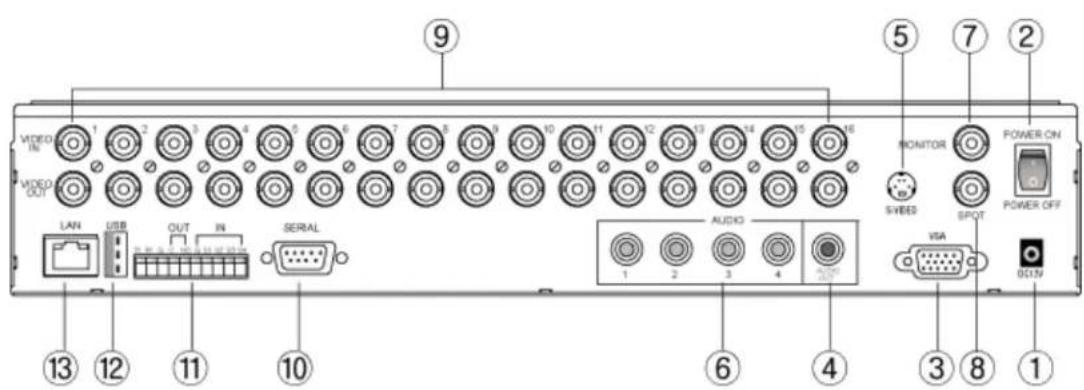
Figure 3 (16ch Model)
① Power input – conneccon port for DC 12 volt
② Toggle Power Switch – POWER ON and POWER OFF switch that turns unit on and o
③ VGA (Video Graphics Array) Port – Locaon where VGA monitor cable must be inserted
④ Audio Out – Mono RCA, 1Vpp, 10k ohm
⑤ S-Video – S-Video out conneccon
⑥ Audio Input – Mono RCA, 1Vpp, 10k ohm, available in 4 channels
⑦ Main Monitor Output – BNC main monitor output
⑧ SPOT Monitor Output – Secondary monitor output for public display
⑨ Camera Input / Video Loop Out – Analog Type BNC camera plug-in locaon and video loop out
⑩ Serial Connecon - 9 pole D-Type male connector
⑪ PTZ, Sensor, Alarm Out Port – Single TX(+), single RX(-), 1 Alarm out, 4 Sensor In via pluggable 10-way terminal block
⑫ USB Port – Connecon for USB mouse or for small USB memory device
⑬ Network Port – Ethernet port
Chapter 2. Hardware Description
3. Rear Port Specification and Connection Examples
3. Rear Port Specicaon and Connecon Examples
Power input

Input at 12 volt DC with positive polarity at 5 Amp
[Please refer to the Figure 1 (4ch Model), Figure 2 (9ch Model), Figure 3 (16ch Model) item marked “①” Power input].
VGA (Video Graphics Array) Port
VGA port uses D-subminiature or D-sub, DE-15F (E rated sized D-Sub with 15 pin Female) port.
Connect a VGA monitor to the DVR with a standard VGA Cable. We recommend using a 17" LCD or CRT monitor or above.

Figure 4 VGA Connecon Conguraon
Supported resoluons for the VGA ports are:
800x600 @ 60Hz/75Hz
1024x768 @ 60Hz/75Hz
1280x1024 @ 60Hz/75Hz
*All resoluons display at True Color 32 Bit
Chapter 2. Hardware Description
3. Rear Port Specification and Connection Examples
natural_image
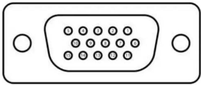
Front view of a V12D D-sub connector with 15 pin labels (no text or symbols beyond pin numbers)Figure 5. VGA Pin Conguraon
[Please refer to the Figure 1 (4ch Model), Figure 2 (9ch Model), Figure 3 (16ch Model) item marked “③” VGA Port].
VGA Pin Conguraon Table
| Signal Type | Pin Number | Descripon |
| RED | 1 | Red video (75 ohm, 0.7 V p-p) |
| GREEN | 2 | Green video (75 ohm, 0.7 V p-p) |
| BLUE | 3 | Blue video (75 ohm, 0.7 V p-p) |
| RES | 4 | Reserved |
| GND | 5 | Ground |
| RGND | 6 | Red ground (Red return) |
| GGND | 7 | Green ground (Green return) |
| BGND | 8 | Blue ground (Blue return) |
| KEY / PWR | 9 | Key (not used) / +5V DC |
| SGND | 10 | Sync ground |
| IDO | 11 | Monitor ID bit 0 |
| SDA | 12 | Bidireconal data line |
| HSYNC or CSYNC | 13 | Horizontal or Composite Sync |
| VSYNC | 14 | Vercal Sync and data clock |
| SCL | 15 | Data clock |
Table 6 VGA Pin Conguraon
Chapter 2. Hardware Description
3. Rear Port Specification and Connection Examples
Main Monitor Output
BNC (Bayonet Neil Concelman or Brish Navel Connector) type 75 ohm.
Connect a monitor that supports BNC Inputs or use a "BNC Twist Lock" to Composite Video adapter if your monitor only supports Composite Video Inputs.

flowchart
graph TD
    A["CH1"] --> B["L1"]
    C["CH2"] --> D["L2"]
    E["CH3"] --> F["L3"]
    G["CH4"] --> H["L4"]
    I["MONITOR"] --> J["SPOT"]
    K["VIDEO IN"] --> L["IN OUT"]
    K --> M["IN OUT"]
Figure 7 Main Monitor Connecon
The display resolution for Monitor is at 720x480.
[Please refer to the Figure 1 (4ch Model), Figure 2 (9ch Model), Figure 3 (16ch Model) item marked “⑦” Main Monitor Output].
SPOT Monitor Output
BNC (Bayonet Neil Concelman or Brish Navel Connector) type 75 ohm.
Connect a monitor that supports BNC Inputs or use a "BNC Twist Lock" to Composite Video.
The display resoluon for Monitor is at 720x480.
[Please refer to the Figure 1 (4ch Model), Figure 2 (9ch Model), Figure 3 (16ch Model) item marked “⑧” SPOT Monitor Output].
Chapter 2. Hardware Description
3. Rear Port Specification and Connection Examples
Camera Input
The camera conncons are the input ports for the video signal(s) used with the DVR. You may use any video source (75ohm) that outputs via a BNC connector (Twist Lock Type). If your video source outputs via RCA/Composite video, the proper adapter must be used when connecng the cable to the camera conncon input port(s) of the DVR. Both NTSC and PAL signals are automatically detected by the DVR and requires no further conguraon.
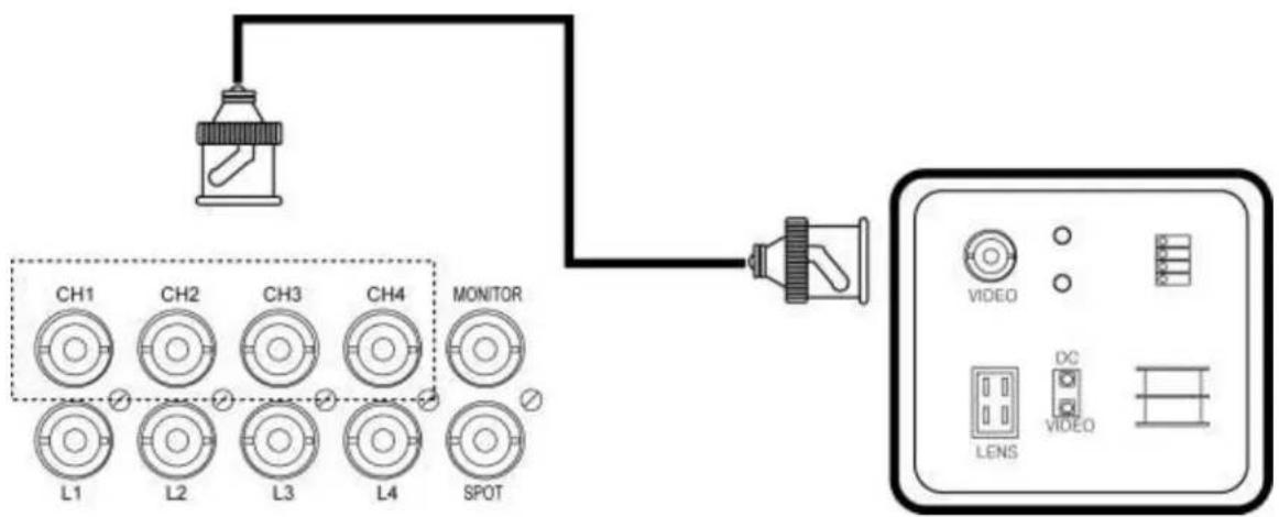
flowchart
graph TD
    A["Paint Bottle"] --> B["Monitor"]
    C["L1 CH1 CH2 CH3 CH4 L1 L2 L3 L4 SPOT"] --> B
    B --> D["Electronic Device"]
    E["Video"] --> F["Display Panel"]
    G["LENS"] --> H["Device Icon"]
    I["DC"] --> J["Device Icon"]
Figure 8 Camera Connecon
Connect the cameras to the Video In ports located on the rear panel of the DVR using the proper cables and connectors (BNC Twist Lock). The corresponding video channels can be "looped" out using the "loop out" ports located beneath each video input port. There is no need for terminators to be installed, each port is self terminated. Both NTSC and PAL signals are automatically detected by the DVR and requires no further conguraon.
[Please refer to the Figure 1 (4ch Model), Figure 2 (9ch Model), Figure 3 (16ch Model) item marked “⑨” Camera Input / Video Loop Out].
RS-232 Serial Connector
RS-232 port uses D-subminiature or D-sub, DE-9M (E rated sized D-Sub with 9 pin Male) port.
Chapter 2. Hardware Description
3. Rear Port Specification and Connection Examples
The RS-232 COM port is used to connect the DVR to a PC (oponal updang procedure) or to connect an external device like a DVR controller (oponal). The required sengs to use the RS-232 port can be congured in the DVR sengs.
Connecon Type: 9 pole D-Type male connector
Maximum Input Voltage: +/- 25V
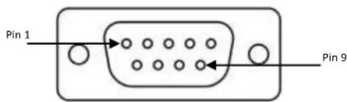
Figure 9 DE-9M Serial Port
[Please refer to the Figure 1 (4ch Model), Figure 2 (9ch Model), Figure 3 (16ch Model) item marked “⑩” Serial Connecon].
RS-232 / DE-9M Serial Port Pin Conguraon Table
| Signal Type | Pin Number | Descripon |
| DCD In | 1 | Carrier Detecon Signal (not used) |
| Rx | 2 | RS232 Receive |
| Tx | 3 | RS232 Transmit |
| N/C | 4 | No Connecon |
| GND | 5 | System Ground |
| N/C | 6 | No Connecon |
| RTS | 7 | RS232 Request To Send Signal |
| CTS | 8 | RS232 Clear To Send Signal |
| N/C | 9 | No Connecon |
Table 10. RS-232 pin conguraon
Chapter 2. Hardware Description
3. Rear Port Specification and Connection Examples
Oponal Alarm Sensor Extension Box
There is oponal Alarm Sensor Extension Box that connects to RS-232 port provided in our DVR unit.

① Power switch
② Power adaptor connector
③ RS-232 port (Port connected to the system)
④ Sensor input (1\~16)
⑤ Normal Open alarm output : 1\~16
⑥ Normal Close alarm output : 1\~16

Figure 11 Connecon Example of Extension Box
Sensor 1\~16 inputs funcons same as the S1\~S4 inputs (see next secon in 10-way terminal Block). Dierence is that every port is issued with its own ground conncon located right below. Additionally there are 16 NO (Normally Open) dry contact points with dedicated ground and 16 NC (Normally Closed) dry contact point with dedicated ground per points. These NO, NC points are used in Access control integraon.
Chapter 2. Hardware Description
3. Rear Port Specification and Connection Examples

flowchart
graph TD
    A["Alarm Panel"] --> B["B"]
    B --> C["Sensor 2"]
    C --> D["Relay Switch"]
    D --> E["NO output Dry Contact"]
    D --> F["NC output Dry Contact"]
    G["Arm or Dis-Arm information"] --> H["+5V"]
    H --> I["12V DC"]
    I --> J["PGM1"]
    J --> K["Relay Switch"]
    K --> L["+3V DC"]
Figure 12 Alarm Sensor Extension Box Wire Example
10-Way Terminal Block
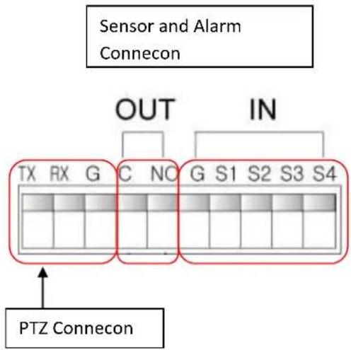
There are RS-485, Alarm Output, and Sensor Input (1 to 4 Sensor) all located in 10-Way Terminal Block.
| Signal Type | Pin Number | Descripon |
| Tx | 1 | RS-485 Transmit |
| Rx | 2 | RS-485 Receive |
| G | 3 | Ground (RS-485) |
| C | 4 | Common (Ground for Alarm Out) |
| NO | 5 | Normally Open (Alarm Out) |
| G | 6 | Ground (Sensor) |
| S1 | 7 | sensor conncon port 1 |
| S2 | 8 | sensor conncon port 2 |
| S3 | 9 | sensor conncon port 3 |
| S4 | 10 | sensor conncon port 4 |
Table 13. 10-Way terminal block pin-out
Chapter 2. Hardware Description
3. Rear Port Specification and Connection Examples
Specicaon for 10-Way terminal block
Rated current: 8A
Contact resistance: 20m
Insulaon resistance: 5000M/1000V
Withstanding Voltage: AC1500V/1Min
Wire range: 18AWG 1mm ^4
Mechanical
Temp. Range: -40°C\~+105°C
MAX Soldering: +250°C for 5 Sec.
Strip length: 5-6mm
Alarm Out Voltage: 5vt

Figure 14 10-Way terminal block
Warning
"S1\~S4" port emits +5 volt current out from its ports. Some alarm panels may be damaged if improper voltages are introduced. Please consult your alarm panel documentaon for applicaon requiring such conncon.
[Please refer to the Figure 1 (4ch Model), Figure 2 (9ch Model), Figure 3 (16ch Model) item marked “⑪” PTZ, Sensor, Alarm Out Port].
RS-485 Connecons
The RS-485 ports are used to connect external PTZ cameras to the DVR. There is single available port with this DVR. External controllers may be used, however you will not have the ability to control the PTZ cameras remotely if you do so.
There are single RS-485 communicaons ports, these ports are used to connect external PTZ camera controllers.
Chapter 2. Hardware Description
3. Rear Port Specification and Connection Examples
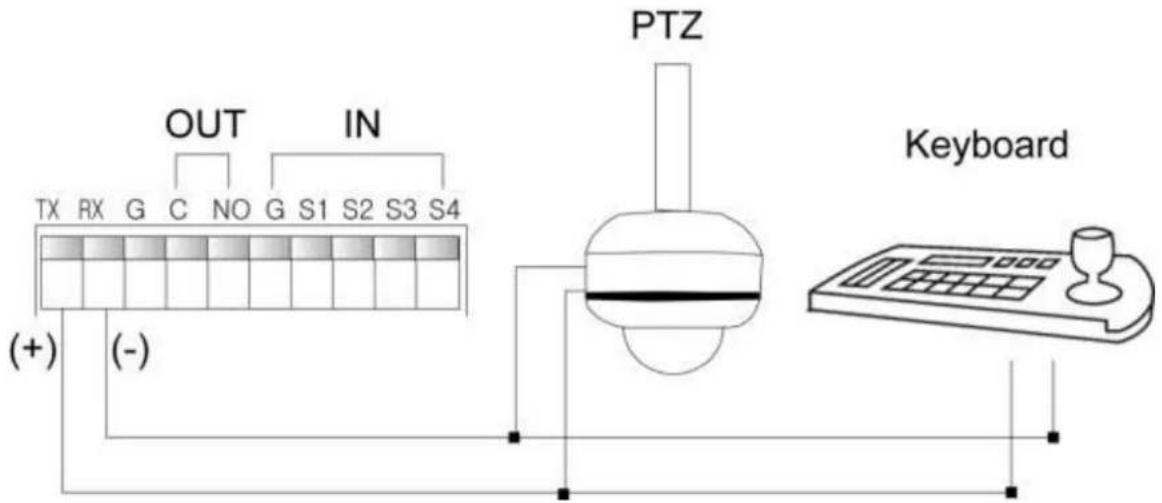
Figure 15 PTZ and Keyboard in RS-485
Alarm Out
Connecng the alarm out:
Each alarm output can be controlled/switched by DVR unit and its application soware. Each device must be wired to C (Common) and NO (Normally Open). It passes no voltage (dry contact)

Figure 16 Alarm Out
Sensor Input
Connecng the Inputs:
Each alarm input can be controlled/switched by a device such as a moon/IR sensor, door contact sensor, and similar devices. Each device can either be wired as N/O or N/C (Normally Open/Normally Closed).
Specicaons:
Alarm Input: +5v
Chapter 2. Hardware Description
3. Rear Port Specification and Connection Examples
Input Voltage Range: -5VDC (minimum) to 40VDC (maximum)
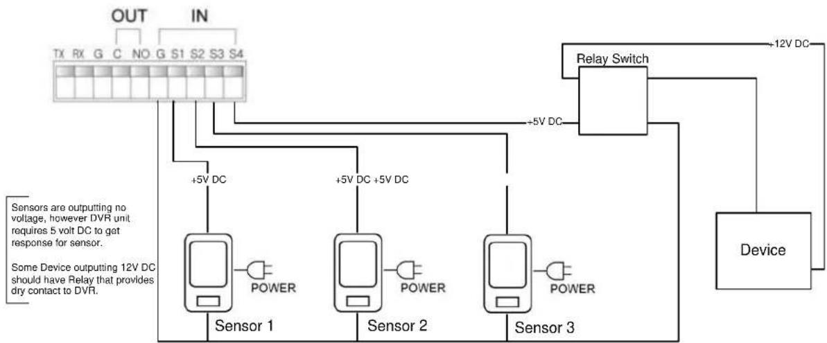
Example 1. Dry contact sensor direct to DVR
This example is the simplest form of sensor conncon for DVR unit. Sensors dedicated only for the funcon for the DVR and example below depicts that Moon Sensors are not outpung any type of voltage (dry contact).
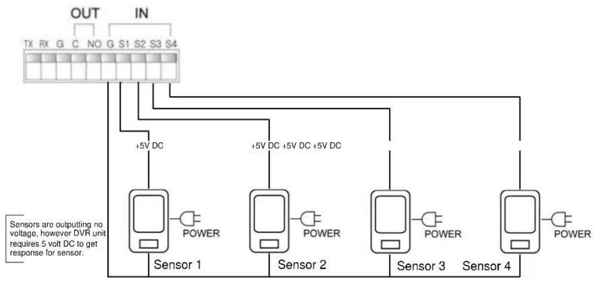
Figure 17 Basic Sensor Connecon
Example 2. Dry contact and 12 Volt DC combinaon direct to DVR
For some installaon you may have sensors outpung dierent voltage that may require voltage conversion device.
Chapter 2. Hardware Description
3. Rear Port Specification and Connection Examples
flowchart
graph TD
    A["Sensor 1"] -->|+5V DC| B["Relay Switch"]
    C["Sensor 2"] -->|+5V DC +5V DC| B
    D["Sensor 3"] -->|-5V DC| B
    B --> E["Device"]
    style A fill:#f9f,stroke:#333
    style C fill:#f9f,stroke:#333
    style D fill:#f9f,stroke:#333
    style B fill:#ccf,stroke:#333
    note right of A: Sensor is outputting no voltage, requiring 5 volt DC to get response for sensor.
    note right of C should have Relay that provides dry contact to DVR.
Figure 18 Sensor input with 3 volt DC
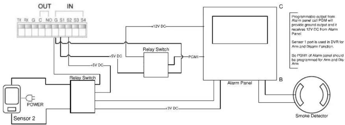
Example 3. Alarm panel integraon with Dry and Wet sensor.
Dry sensors (sensors with no voltage) and Wet sensors (sensors that put out voltage) are readily available to be used with our DVR unit.
Most of the alarm panel that exist today requires some type of Direct Current Voltage from sensors and it also has programmable relay-out conneccon called PGM available to alarm panel. PGM is used to follow programmed conditions in alarm panel (EX: if smoke detector is sensed then send the signal to re department and trip 12 volt DC to PGM output where DVR unit will receive the such event through relay switch. It is critical that voltage regulang relay board to be introduced in this type of installaon or else DVR unit will be damaged by introducing higher voltage to the unit.)
flowchart
graph TD
    A["Sensor 2"] --> B["Relay Switch"]
    B --> C["Relay Switch"]
    C --> D["PGM1"]
    D --> E["Alarm Panel"]
    E --> F["Smoke Detector"]
    G["TX RX G C NO G S1 S2 S3 S4 OUT IN"] --> H["+5V DC"]
    H --> I["+12V DC"]
    I --> J["+3V DC"]
    J --> K["+5V DC"]
    K --> L["+12V DC"]
    L --> M["+5V DC"]
    M --> N["+12V DC"]
    N --> O["+5V DC"]
    O --> P["+12V DC"]
    P --> Q["+5V DC"]
    Q --> R["+12V DC"]
    R --> S["+5V DC"]
    S --> T["+12V DC"]
    T --> U["+5V DC"]
    U --> V["+12V DC"]
    V --> W["+5V DC"]
    W --> X["+12V DC"]
    X --> Y["+5V DC"]
    Y --> Z["+12V DC"]
    Z --> AA["+5V DC"]
    AA --> AB["+12V DC"]
    AB --> AC["+5V DC"]
    AC --> AD["+12V DC"]
    AD --> AE["+5V DC"]
    AE --> AF["+12V DC"]
    AF --> AG["+5V DC"]
    AG --> AH["+12V DC"]
    AH --> AI["+5V DC"]
    AI --> AJ["+12V DC"]
    AJ --> AK["+5V DC"]
    AK --> AL["+12V DC"]
    AL --> AM["+5V DC"]
    AM --> AN["+12V DC"]
    AN --> AO["+5V DC"]
    AO --> AP["+12V DC"]
    AP --> AQ["+5V DC"]
    AQ --> AR["+12V DC"]
    AR --> AS["+5V DC"]
    AS --> AT["+12V DC"]
    AT --> AU["+5V DC"]
    AU --> AV["+12V DC"]
    AV --> AW["+5V DC"]
    AW --> AX["+12V DC"]
    AX --> AY["+5V DC"]
Figure 19 Alarm Panel and Sensor Example
Chapter 2. Hardware Description
3. Rear Port Specification and Connection Examples
USB Connecon
The USB conncon ports are used for both back up and mouse control purposes. Either port can be used for back up via USB memory sck or for mouse control. A third opon for the two USB ports are for rmware updang procedures. You will only need to use one port for rmware updates.
Two USB ports are located one front side of the DVR and the other in rear side of the DVR. These ports may be used for both USB mouse conncon and for USB memory sick back up procedures
[Please refer to the Figure 1 (4ch Model), Figure 2 (9ch Model), Figure 3 (16ch Model) item marked “⑫” USB Port].
Ethernet Port
The RJ-45 port is used to connect the DVR to a network through a DTE (Data Terminal Equipment) device such as a switch or router with an integrated switch. To connect the system to a network please use a standard RJ-45 cable (patch/straight through) and make sure both ends of the cable are securely connected to the proper ports. Consult your local IT administrator for detailed conguraon procedures and setup. The maximum cable length for Category 5e, RJ-45 cable is 100 meter or 300 feet.
Ethernet Specicaons
Connecon: 10/100/1000 Base T, IEEE 802.3Dierenal signal voltage: ± 2.8 V maximum, inputs have transient overvoltage protecon
Ethernet port details: EEE 802.3/802.3u - 100Base-TX/10Base-T physical layer
Auto negoaon: 10/100, full/half duplex
Cable length: 100 meters (100 ohm unshielded twisted pair cable or 150 ohm shielded twisted pair cable, category 5 or higher).
Impedance: built-in compensaon for impedance matching
Indicators: ACT, 10/100
Chapter 2. Hardware Description
3. Rear Port Specification and Connection Examples

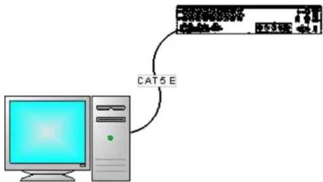
This type of conncon is used mostly for tesng the DVR unit and for simple and short cable conncon. Since there is no devices providing DHCP services you must x your IP address to stac IP address (discussed on Chapter Chapter 11. Network Secon In-Depth from page 105) to your DVR as well as your PC. If this is not done properly, then there connectivity of the unit to the PC will not happen.
Chapter 2. Hardware Description
3. Rear Port Specification and Connection Examples
First you must use cross over network cable. This is a cable created with crossing pin 1 to 3, 2 to 6 then pin 3 to 1, 6 to 2.

Figure 22 Cross Over Cable
You may now connect directly into PC and DVR unit to communicate directly. Your DVR gateway address and PC's gateway address must be same address. Then you must assign TCP/IP address that belongs to same subnet address as DVR and PC.
Example IP address for DVR
DVR TCP/IP address: 192.168.0.2 PC's TCP/IP address 192.168.0.3
DVR's subnet: 255.255.255.0 PC's subnet: 255.255.255.0
DVR's gateway: 192.168.0.1
PC's gateway: 192.168.0.1
flowchart
graph TD
    A["Computer"] -->|CAT5 E| B["User Interface"]
Figure 23. Direct PC Connecon
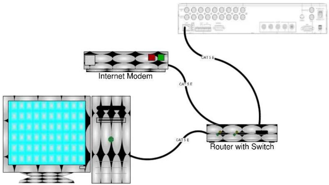
Example 2. Connecng DVR unit to Router
This is most common conncon for DVR it is advised that your DVR follow the rules of network policy (Please consult with your network administrator).
In this example we are going to assume that router is giving (leasing) TCP/IP address. When router is giving TCP/IP address to the unit this acon is possible via Dynamic Host Control Protocol otherwise known as DHCP.
Chapter 2. Hardware Description
3. Rear Port Specification and Connection Examples
flowchart
graph TD
    A["Internet Modem"] -->|CAT 5 E| B["Router with Switch"]
    B -->|CAT 5 E| A
Figure 24 Modem and Router Conguraon

flowchart
graph TD
    A["Computer"] -->|CAT 5E| B["Internet Modem / Router Switch"]
    B -->|CAT 5E| A
Figure 25 Internet Modem with Router Switch
- Front Panel

Figure 26 Front Panel
| No. | Buon | Descripon | |
| 1 | Direconal Buon | Use as Control buon in Setup Menu (move up, down, le, right) | |
| Use as Control buon in Playback (Pause, Play, Stop, Rewind, Fast Forward) | |||
| 2 | Menu | Call the setup menu. Move to previous step in setup menu. | |
| 3 | PTZ | Call the PTZ menu | |
| 4 | Audio | Call the Audio menu | |
| 5 | Backup | Call the Backup menu | |
| 6 | Numeric Buons | Select a channel or enter a number. | |
| 7 | LED | The status of Power, Record, Network, Schedule and Emergency. | |
| 8 | Funcon Buons | Search | Call the Search Menu |
| QUAD | Change a split mode | ||
| SEQ | Start sequenal display | ||
| Schedule | Switch to schedule record mode. | ||
| Emergency | Switch to Emergency record mode | ||
Chapter 2. Hardware Description
3. Front Panel
⑨
Front USB Port
Connect a USB mouse or USB drive.
⑩
ODD
Oponal ODD is able to install.
4. Remote Controller
 | 1 | ID |
| 2 | QUAD | |
| 3 | BACKUP | |
| 4 | AUDIO | |
| 5 | SEQ (Sequence) | |
| 6 | PTZ | |
| 7 | SEARCH | |
| 8 | NUMERIC BUTTONS | |
| 9 | MENU | |
| 10 | DIRECTION BUTTONS | |
| 11 | EMERGENCY | |
| 12 | SCHEDULE |
Chapter 3. Quick Setup
1. Placement
Step 1. Preparaon
Remove unit from out of the box and place it on the table top as seen below.

natural_image
Black H.264 digital video camera on a desk with a paper sheet nearby (no visible text or symbols on the device body)Figure 27 Table top placement
2. Connecon
Aer unpacking the unit you must connect all camera connecons, monitor connecons, network conncon, power conncon and other oponal connecons.
Step 1. Connect Cameras to DVR unit

natural_image
Close-up of a hand holding a USB cable, with a computer tower visible in the background (no text or symbols)Figure 29 Camera to DVR
Repeat this for number of cameras you are connecng to the DVR unit.
Example: If you are connecng 3 camera in 4ch DVR unit start with CH1 then to CH2 and nish to CH3 and do not connect to CH4
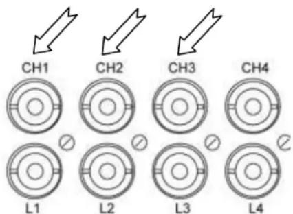
Figure 28 Example of 3 Camera Connecons
Chapter 3. Quick Setup
2. Connection
Step 2. Connect monitor to DVR unit

natural_image
Close-up of hands inserting a blue USB cable into an audio device labeled 'AUDIO' (no additional text or symbols visible)Depending on what type of monitor you are conneccon connect either to VGA or BNC monitor of your choice. If you have both types of monitor you may connect both of them.
Figure 30 VGA or Monitor Connecon
Step 3. Connect Network Cable to DVR unit

natural_image
Close-up of a hand inserting a USB into an audio device (no visible text or symbols)Figure 31 Ethernet Cable to DVR Unit
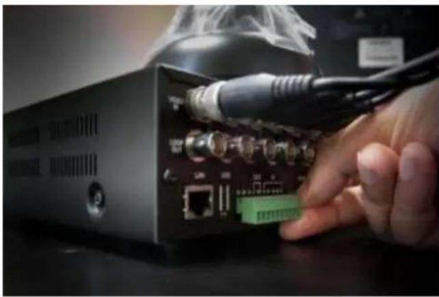
Step 3. Oponal PTZ, Sensor, Alarm
natural_image
Hand inserting a USB cable into a black audio equipment module with ports and connectors (no visible text or symbols)Figure 32 10-Way Terminal Block Connecon
3. Quick Power On
Power input – conneccon port for DC 12 volt
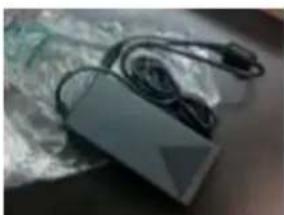
Step 1. Included DC Power adapter is located in accessory box.

natural_image
Open cardboard box containing a small electronic device and accessories (no visible text or symbols)Step 2. Take the adapter and connect it with power cord.
natural_image
Exterior view of a modern office building (no signage)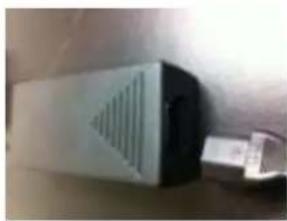
natural_image
Exterior view of a silver electronic device with ventilation grille and USB cable (no text or symbols visible)Step 3. Connect the DC 12V male connector to female DC 12V port.

Step 4. Connect to the wall outlet then press upward to POWER ON switch.

natural_image
Hand inserting a plug into an electrical outlet (no visible text or symbols)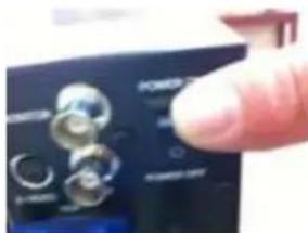
4. Inial Boot
Aer turning on the DVR unit it will go into a boot sequence. At the initial boot secon there is no user interacon with DVR unit however please observe to see if DVR unit is properly boong.

natural_image
Pixelated graphic of a black square with green and white crosses above a red horizontal bar (no text or symbols)Figure 34 Inial Boot screen

natural_image
Simple diagram showing a red rod and a green block above an arrow, no text or symbols present.Figure 33 Boong in progress
As you may noce progress bar will indicate boong
progression, if there is no acvity for long period of me then possible corrupt or damaged rmware in DVR unit. Please
indicate such failure and contact technical support.

Figure 35 Live Screen View
If you have camera properly connected you will see cameras conncon as indicated in gure 34 in CH1 and CH2 but if you do not have camera connect as you see in Ch3 and Ch4 you will see "VIDEO LOSS" indicaon as you see in above gure. Please check your cable conncon if you have
5. Setup Screen
To initiate setup menu you may use following method
Mouse
Right mouse click anywhere on the screen of DVR
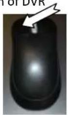
Remote
Press bu on labeled "Menu" on remote controller

natural_image
Illustration of a remote control with an arrow pointing to the right (no text or symbols)Frontal Keypad
Pressing bu on labeled "Menu" on front of DVR unit's direconal key pad buon.

By using any method shown above there will be setup menu screen shown below

Figure 36 Setup Menu
From the setup screen you have opon to choose System, Search, Backup, ER (emergency), PTZ, and Sound opons. You also have opon to see the log informaon from Warning secon, change orientaon from the split opon, how to group the view from Group opon, and to auto sequence and to automacally lock out DVR by Log out opon.
6. Change Password and Enable Auto Lock
It is critical that you change the password and create user access to the DVR. By default admin password is 11111111 and user password is also 11111111. As default, you will be logged in as administrator and will have full privileges as administrator. As cauon formang HDD, Factory Reset opon and changing administrator password you must input administrator's password as con rma on even if you have login as administer other seng such as network conguraon and me parameters are vulnerable if you do not enable auto locking feature and change administrator's password.
Step 1. Select system item form main menu

Figure 37 Select system item from setup menu
Step 2. Select Password tab on the le.

Figure 38 Password Tab
Chapter 3. Quick Setup
6. Change Password and Enable Auto Lock
Step 3. Choose the type of login account you want to change password to. In this example we would like to change the administer account. You may scroll though type of users that DVR will have by clicking the black reverse and forward arrow.

Figure 39 Selecng Accounts.
Or when user secon is shown with orange color with black reverse and forward arrow, use the navigaonal buon to toggle through type of users.
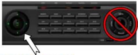
Figure 40 Navigaonal Buon
Do not confuse the navigaonal buon with menu, PTZ, Backup buons on the right.
Step 4. Navigate down to Password eld secon then press enter or le click on the mouse.

Figure 41 Password Field
You will now see a screen as shown on gure below.

Figure 42 Current Password
Step 5. When you select the area where you could type, numeric keypad will be shown as depicted on Figure 43 Numeric Keypad and Password Conrmaon.
Chapter 3. Quick Setup
6. Change Password and Enable Auto Lock

Figure 43 Numeric Keypad and Password Conrmaon
Here you will be entering current password. Input the password into the numeric keypad and then conrm by selecng OK. Then you will need to end it with OK buon.
You need now to input with new password input process. Numeric keypad will appear where desired password could be entered. The password is limited in numeric combinaon 1 to 8 digit combinaon.

Figure 44 New Password Conrmaon
Step 6. You need to repeat one more me for new password conrmaon.
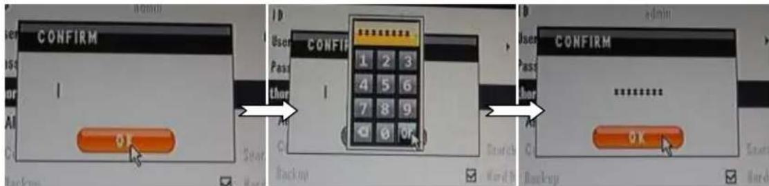
Figure 45 Second Conrmaon of New Password
Step 7. Apply the seng and conrm.

Figure 46 Apply the seng
Chapter 3. Quick Setup
6. Change Password and Enable Auto Lock
Step 8. Under Buon Sengs secon, you will have opon to choose Auto Key Lock and Emergency Lock opon. As default both secon is disabled as you see in below gure.
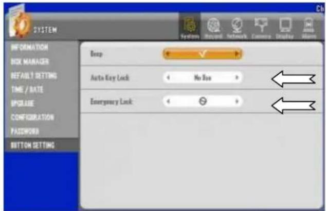
Auto Key Lock will calculate idle me of user intervenon and auto me lock the DVR Unit.
Emergency Lock will enable user to input the password every me aer setup menu is exited, forcing the user to input password to be in setup menu.
As a good pracce we recommend that you enable both of these features specially if this DVR is being place where few or more person may have access to this unit physically.
Choose desire me by toggling between the me selecon as shown.

Figure 47 Auto Key Lock Selecon
Also choose to enable Emergency Lock as shown below.

Figure 48 Emergency Lock
Apply the seng then exit.
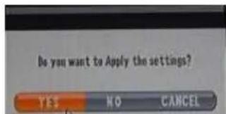
Figure 49 Apply and Exit
7. Labeling Camera
Someme camera locaon may be idened easier by giving logical name to the camera. Here are steps to give logical name label instead of having default label.
Step 1. Select "Camera" item on upper main category and select CAMERA TITLE
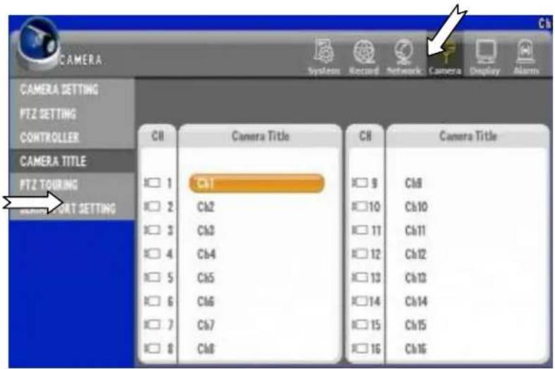
Figure 50 Camera Title Menu
Here you may choose camera(s) that you want to give logical name and repeat to other camera(s) as needed. In this example we have chosen Camera 1 marked Ch1 and will change the label to door1.
Step 2. Click Camera Number to change then use the on screen key pad to change the label as shown below. When done giving name select and choose OK to end typing.

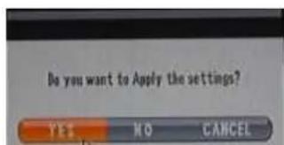
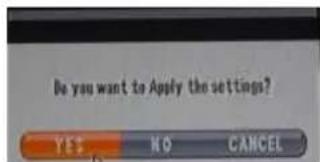
Step 3. Exit the menu and select YES to apply the seng
8. Enable Recording
Main and primary funcon of DVR is to record video. Below secon is showing how to conjure all cameras to record immediately. DVR already may be congured to record on the HDD. It is always
Step 1. Select "Record" item on upper main category then by default "EVENT RECORDING" tab should appear as shown on screen below.

Figure 51 Event Recording Page
There are 3 types of resoluon that you may choose 360X240, 720X240, or 720X480.
360X240 is lowest possible resoluon seng for this unit, 720X240 being the second best resoluon, and 720X480 is most dened resoluon seng you could choose. Judging from 360X240, 720X240 will yield 2X more clarity but however you may have twice more consumpon on hard disk space. 720X240 will have 4X more clarity but disk space will be decreased by 75% if this resoluon is chosen.
Therefore careful planning and priorizing the importance of each camera is required when rst seng up the DVR. One other element is the speed of recording. fps (frames per second) seng. For screen resoluon at 360X240 you may record at 30fps that, 720X240 resoluon you must stay below 15fps to have equal amount of space allocaon in HDD, and for resoluon at 720X480 you must choose 7.5fps to have equal amount of space allocaon in HDD. Lastly there is also picture quality seng that has 5 step quality elements that impacts HDD allocaon as well.
Step 2. Enable Event Recording.

Chapter 3. Quick Setup
8. Enable Recording
Step 3. Globally con gure all cameras to record by clicking on "All" mark to enable all cameras then set resoluon to desired seng.

Step 4. Choose fps seng globally and do not exceed base fps. In the picture example is 480fps as base fps.

Step 5. Chose picture quality seng.

Step 6. Exit and conrm changes.
9. Prepare Network
Step 1. Select "Network" item on upper main category then by default "IP ADDRESS" tab should appear as shown on screen below.

Figure 52 IP ADRESS Page
Make sure that DHCP is selected if you have a router that leases IP address to network. If you want to give the IP Address value to unit directly then uncheck the DHCP check box and input IP Address directly where ← (Arrow) is poing to. Also make sure to assign proper port number as shown above.
Important Note: when to use DHCP vs. Stac IP
DHCP is short for Dynamic Host Communicaon Protocol where IP address is given to the DVR and these IP address are leased to the unit. Usually IP address are none routable internal IP Address. Internal IP address or known as Private IPv4 address, they may be starng with 192.168.0.0 \~ 192.168.254.254 (16-bit block enabling 65,536 IP address set) also known as class C IP address, 172.16.0.0 \~ 172.31.254.254 (20-bit block enabling 1,048,576 IP address set) also known as class B address, or 10.0.0.0 \~ 10.254.254.254 (24-bit block enabling 16,777,216 IP address set) also known as class A address. So if your router or DHCP server gives the IP address that are class A, B, or C address shown then you can conrm that there is a DHCP services available on your network but if you get IP address ranging from 169.254.1.0 \~ 169.254.254.255 then you have been assigned pseudorandom IP address and it is a indicaon that there are no DHCP service available for DVR device.
Stac IP seng is used when your ISP (Internet Service Provider) gives routable IP they are call Public IPv4 address. They are IP address that points to the DVR unit without relying on DHCP service. In situaton such as this case you may congure IP address as recommended by ISP. Oen mes Stac IP is
Chapter 3. Quick Setup
9. Prepare Network
sll used with class A, B, or C address. In those cases, you must point to IP addresses that are not in lease range of the DHCP scope (IP address not issued by DHCP services but must be in same Subnet and Gateway IP). Users tend to use this method when certain IP address out of DHCP scope where parcular IPs are congured to use NAT, IP forwarding, or DMZ (NAT, IP forwarding and DMZ are used in most router to enable incoming trac to spec IP addresses).
Step 2. Congure Port for incoming trac. You must have NAT, IP forwarding or DMZ congured in your router in order to allow in bound trac to your network. And Port assign to allow inbound trac to local IP assign to DVR should be identical to Port conguraon with DVR. See gure below but your router conguraon page might look dierent.

Figure 53 Port Forwarding Example
On Figure 53 Port Forwarding Example we are showing how Port forwarding is done in router and DVR.
Step 3. Exit and conrm changes.

All above steps menoned in Chapter 3. Quick Setup will ensure that you will have DVR connect to Cameras, enabled recording and basic network conguraon.
Chapter 4. Main Menu (Root Menu)
There are 6 items shown on Main Menu or Root Menu. They are “system”, “search”, “backup”, “ER”, “PTZ” and “sound”. There are also “Warning”, “Split”, “Group”, “Auto Sequence” and “Log out” set of items below Main Menu items.
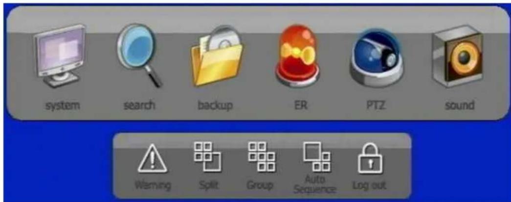
Figure 54 Main Menu Items
1. Main Items.
The “system” item is used to con gure DVR unit. The “search” item is used to conduct search and playback the video on DVR unit. The “backup” item is used to conduct backup o to USB memory device or other media. The “ER” is emergency recording func on. The “PTZ” is used control PTZ camera and nally the “sound” is used operate sound.
2. Sub operaonal items.
The “Warning” opon will indicate any deciency with DVR unit such as HDD error and Network Error types.
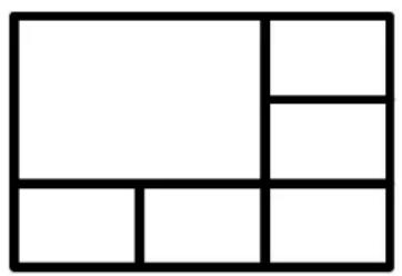
The "Split" items shows screen conguraon with following layout.

natural_image
Empty white rectangle with black border (no text or symbols)Single View

natural_image
Simple geometric grid of four equal squares with no text or symbolsQuad View 6 View
natural_image
Pure geometric diagram of a rectangle divided into six smaller rectangles, no text or symbols present.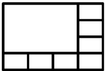
natural_image
Pure geometric diagram of a rectangle divided into smaller rectangles by lines (no text or symbols)8 View 9 View 10 View

natural_image
Simple 2x2 grid pattern with no text or symbols
natural_image
Pure geometric grid pattern with no text, numbers, or symbols
natural_image
Pure geometric grid pattern with no text, numbers, or symbols13 View 16 View
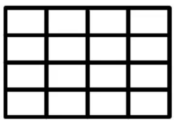
natural_image
Grid pattern with 10 cells outlined in black (no text or symbols)With "Group" will goggle to the next set of cameras available.
With "Log out" user will need to have right user creden al to log back in next me.
Chapter 5. The "System" Root Menu Item
Convenon of Menu Tree
To quickly understand nature of each eld, items selectable in each eld, possible selecon combinaon of the eld, behavior of each eld and types of informaon shown by each eld are graphically illustrated by using hierarchical organizaon using Tree illustraon. There is Root Menu which is Main Menu and there are items which we would now refer them as branches.
Menu Tree will show all type of elds that are present in GUI of the DVR unit. Convenons of the menu tree are organized as follows.

Figure 55 Root Menu
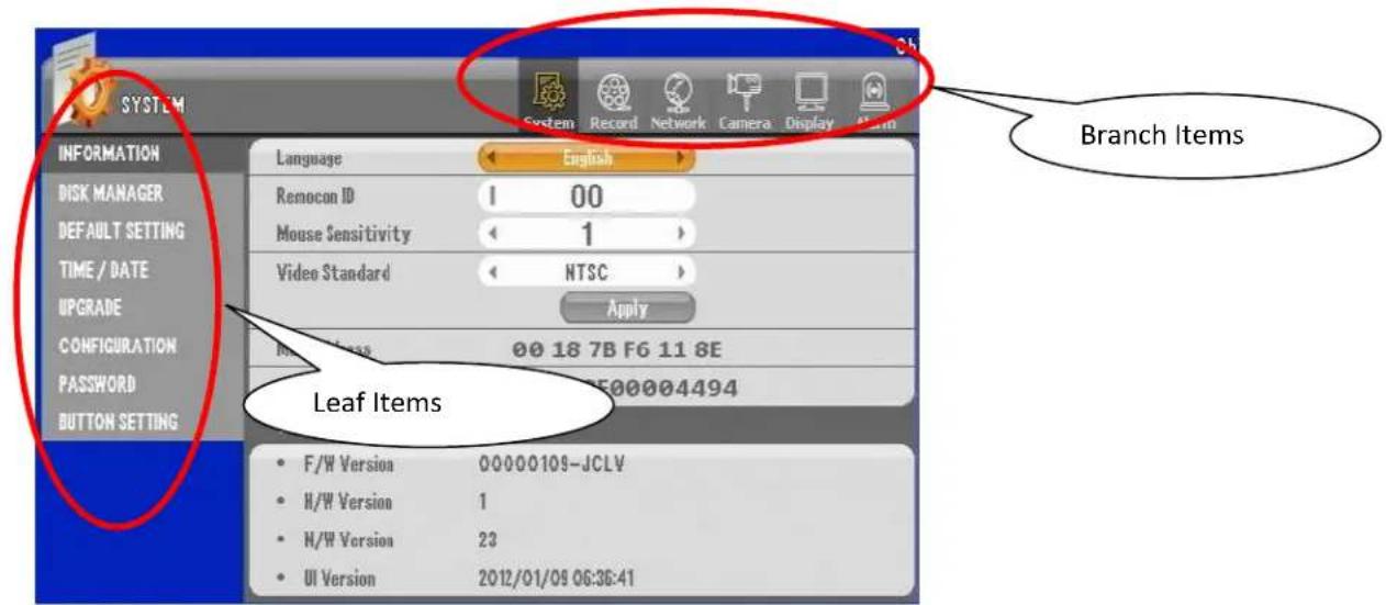
Figure 56 System Branch with INFORMATION Leaf

flowchart
graph TD
    A["Disk 1"] --> B["Field that are selectable"]
    C["CD/DVD RW"] --> D["Field that are not selectable"]
    E["(Selectable) 1, 2, 3"] --> F["Field notes and possible selecon"]
- The "System" Branch

flowchart
graph TD
    A["System"] --> B["INFORMATION"]
    B --> C["Disk 1"]
    B --> D["Disk 2"]
    B --> E["Error List"]
    B --> F["S.M.A.R.T"]
    B --> G["CD/DVD RW"]
    B --> H["Overwrite"]
    B --> I["Auto Delete"]
    B --> J["Default Setting"]
    B --> K["Factory Default"]
    C --> L["(Selectable) Format\n(None Selectable)\n%MB written"]
    D --> M["(Selectable) Delete\n(None Selectable)\nLogs"]
    E --> N["(Selectable) Internal Buzzer\nOn or Off\nDisk 1 and 2 Temperature"]
    F --> O["(None Selectable)\nView Only"]
    G --> P["(Selectable) On or Off"]
    H --> Q["(Selectable) 3 digit numeric\nIncluding 000"]
    L --> R["Language"]
    M --> S["Remocon ID"]
    N --> T["Mouse Sensitivity"]
    O --> U["Video Standard"]
    P --> V["Mac Address"]
    Q --> W["F/W Version\nH/W Version\nN/W Version\nUI Version"]
    R --> X["(Selectable) English\nKorean\nJapanese\nRussian\nItalian\nRomanian\nBulgarian\nLithuanian\nFrench\nSpanish"]
    S --> Y["(Selectable) 2 digit numeric\nIncluding 00"]
    T --> Z["(Selectable) 1, 2, 3"]
    U --> AA["(Selectable) NTSC or PAL"]
    V --> AB["(None Selectable)\nView Only"]
    W --> AC["(Selectable) MM/DD/YY\nDD/MM/YY\nYY/MM/DD"]
    X --> AD["(Selectable) URL Input by keyboard or numeric IP address"]
    Y --> AE["(Selectable) ----, 12hrs.\n24hrs"]
    Z --> AF["(Selectable) + or - 15min,\n30min, 1hr interval depending upon actual time zone"]
    AA --> AG["(Selectable) JAN~DEC 12 month\nSun-Sat 7days\n1stWeek~5thWeek + Last Week Hours:Minute"]
    AB --> AH["(Selectable) JAN~DEC 12 month\nSun-Sat 7days\n1stWeek~5thWeek + Last Week Hours:Minute"]
    AC --> AI["(Selectable) JAN~DEC 12 month\nSun-Sat 7days\n1stWeek~5thWeek + Last Week Hours:Minute"]
    AD --> AJ["(Selectable) JAN~DEC 12 month\nSun-Sat 7days\n1stWeek~5thWeek + Last Week Hours:Minute"]
    AE --> AK["(Selectable) JAN~DEC 12 month\nSun-Sat 7days\n1stWeek~5thWeek + Last Week Hours:Minute"]
    AF --> AL["(Selectable) JAN~DEC 12 month\nSun-Sat 7days\n1stWeek~5thWeek + Last Week Hours:Minute"]
    AG --> AM["(Selectable) JAN~DEC 12 month\nSun-Sat 7days\n1stWeek~5thWeek + Last Week Hours:Minute"]
    AH --> AN["(Selectable) JAN~DEC 12 month\nSun-Sat 7days\n1stWeek~5thWeek + Last Week Hours:Minute"]
    AI --> AO["(Selectable) JAN~DEC 12 month\nSun-Sat 7days\n1stWeek~5thWeek + Last Week Hours:Minute"]
    AJ --> AP["(Selectable) JAN~DEC 12 month\nSun-Sat 7days\n1stWeek~5thWeek + Last Week Hours:Minute"]
    AK --> AQ["(Selectable) JAN~DEC 12 month\nSun-Sat 7days\n1stWeek~5thWeek + Last Week Hours:Minute"]
    AL --> AR["(Selectable) JAN~DEC 12 month\nSun-Sat 7days\n1stWeek~5thWeek + Last Week Hours:Minute"]
    AM --> AS["(Selectable) JAN~DEC 12 month\nSun-Sat 7days\n1stWeek~5thWeek + Last Week Hours:Minute"]
    AN --> AT["(Selectable) JAN~DEC 12 month\nSun-Sat 7days\n1stWeek~5thWeek + Last Week Hours:Minute"]
    AO --> AU["(Selectable) JAN~DEC 12 month\nSun-Sat 7days\n1stWeek~5thWeek + Last Week Hours:Minute"]
    AP --> AV["(Selectable) JAN~DEC 12 month\nSun-Sat 7days\n1stWeek~5thWeek + Last Week Hours:Minute"]
    AQ --> AW["(Selectable) JAN~DEC 12 month\nSun-Sat 7days\n1stWeek~5thWeek + Last Week Hours:Minute"]
    AR --> AX["(Selectable) JAN~DEC 12 month\nSun-Sat 7days\n1stWeek~5thWeek + Last Week Hours:Minute"]

flowchart
graph TD
    A["System"] --> B["INFORMATION"]
    B --> C["DISK MANAGER"]
    B --> D["DEFAULT SETTING"]
    B --> E["TIME / DATE"]
    B --> F["UPGRADE"]
    B --> G["CONFIGURATION"]
    B --> H["PASSWORD"]
    B --> I["BUTTON SETTING"]

    C --> J["File"]
    C --> K["Upgrade"]
    C --> L["File"]
    C --> M["Configuration Upload"]
    C --> N["Backup"]
    C --> O["User ID"]
    C --> P["ID"]
    C --> Q["User Group"]
    C --> R["Password"]

    L --> S["(Selectable) Shows Files if present"]

    T["(Selectable) Admin"] --> U["(Selectable) Keyboard with alpha and numeric values"]
    V["(User1"] --> U
    W["(User2"] --> U
    X["(User3"] --> U
    Y["(User4"] --> U
    Z["(User5"] --> U
    AA["(User6"] --> U
    AB["(User7"] --> AC["*these are default values"]

    AD["(Selectable) Admin, Super User, User"] --> AE["(Selectable) Numeric only keypad minimum 1 digit to 8 digits"]

    AF["(Selectable) Numeric only keypad minimum 1 digit to 8 digits"] --> AG["(Selectable) Numeric only keypad minimum 1 digit to 8 digits"]

    AH["Beep"] --> AI["(Selectable) On or Off"]

    AJ["Auto Key Lock"] --> AK["(Selectable) No Use 10 Sec 30 Sec 1 Min"]

    AL["Emergency Lock"] --> AM["(Selectable) On or Off"]

    AN["Network Covert All"] --> AO["(Selectable) All available Camera or by individually"]

    AP["Admin"] --> AQ["All Authority Granted"]
    AR["Super User"] --> AS["Config Search Backup granted"]
    AT["User"] --> AU["Backup"]
    AV["Configuration"] --> AW["Search"]
    AX["User"] --> AY["Hard Disk"]
    AZ["User"] --> BA["Record Key"]
    BB["PTZ Control"] --> BC["All"]
    AD --> BD["All Authority Granted"]
    AE --> BE["All Authority Granted"]
    AF --> BF["All Authority Granted"]
    AG --> BG["All Authority Granted"]
    AH --> BH["All Authority Granted"]
    AI --> BI["All Authority Granted"]
    AJ --> BJ["All Authority Granted"]
    AK --> BK["All Authority Granted"]
    AL --> BL["All Authority Granted"]
    AM --> BM["All Authority Granted"]
    AN --> BN["All Authority Granted"]
    AO --> BO["All Authority Granted"]
    AP --> BP["All Authority Granted"]
    AQ --> BQ["All Authority Granted"]
    AR --> BR["All Authority Granted"]
    AS --> BS["All Authority Granted"]
    AT --> BT["All Authority Granted"]
    AU --> BU["All Authority Granted"]
    AV --> BV["All Authority Granted"]
    AZ --> BW["All Authority Granted"]
2. The "Record" Branch

flowchart
graph TD
    A["EVENT RECORDING"] --> B["CH"]
    A --> C["All"]
    A --> D["1~4"]
    A --> E["5~8"]
    A --> F["9~12"]
    A --> G["13~16"]
    B --> H["(Selectable) All available Camera or by individually"]
    C --> I["(Selectable) 360X240 720X240 720X480"]
    D --> J["(Selectable) 1 fps 3 fps 5 fps 7.5 fps 15 fps 30 fps"]
    E --> K["(Selectable) Lowest Low Normal High Highest"]
    F --> L["(Selectable) Lowest to 300 sec In 10 sec interval"]
    G --> M["(Selectable) Option to have it on or off. It enables and disable both Motion and Sensor Event"]
    H --> N["Resolution"]
    I --> O["FPS"]
    J --> P["Quality"]
    K --> Q["Post Record"]
    L --> R["Event Recording"]
    M --> S["Pre Recording"]
    N --> T["(Selectable) Grid showing X axis - 0~24 in block Y axis - SUN~SAT *these block are selectable between Continue(green), Motion(blue), Sensor(red), M+S(orange) and None(gray)"]
    O --> U["(Selectable) Enables and disables pre-recording"]
    P --> V["(Selectable) Enables and disables audio recording"]
    Q --> W["(Selectable) Grid showing X axis - 0~24 in block Y axis - SUN~SAT *these block are selectable between Continue(green), Motion(blue), Sensor(red), M+S(orange) and None(gray)"]
    R --> X["(Selectable) Grid showing X axis - 0~24 in block Y axis - SUN~SAT *these block are selectable between Continue(green), Motion(blue), Sensor(red), M+S(orange) and None(gray)"]
    S --> Y["(Selectable) Grid showing X axis - 0~24 in block Y axis - SUN~SAT *these block are selectable between Continue(green), Motion(blue), Sensor(red), M+S(orange) and None(gray)"]
3. The "Network" Branch

flowchart
graph TD
    A["IP ADDRESS"] --> B["Network FRAME"]
    B --> C["CH"]
    B --> D["fps"]
    B --> E["Quality"]
    C --> F["(Selectable) All channel selection or by individual channel"]
    D --> G["(Selectable) 1 fps 3 fps 5 fps 7.5 fps 15 fps 30 fps"]
    E --> H["(Selectable) Lowest Low Normal High Highest"]
    F --> I["Mail Title"]
    G --> J["Interval"]
    H --> K["Sensor Motion Detection Video Loss Power On Password Modify HDD Error"]
    I --> L["DDNS Server"]
    J --> M["ID"]
    K --> N["Password"]
    L --> O["URL"]
    M --> P["DHCP (on)"]
    N --> Q["DHCP (off)"]
    P --> R["Port"]
    Q --> S["DDNS Address"]
    R --> T["Web Server Port"]
    S --> U["Dual Stream"]
    T --> V["SMTP Server"]
    U --> W["Use Port"]
    V --> X["ID"]
    W --> Y["Password"]
    X --> Z["From (Selected)"]
    Y --> AA["From (Not Selected)"]
    Z --> AB["To"]
    AA --> AC["(None Selectable) Alpha Numeric"]
    AA --> AD["(Selectable) Alpha Numeric Email Address Up to 3 entry"]
    style A fill:#999,stroke:#333
    style B fill:#ccc,stroke:#333
4. The "Camera" Branch
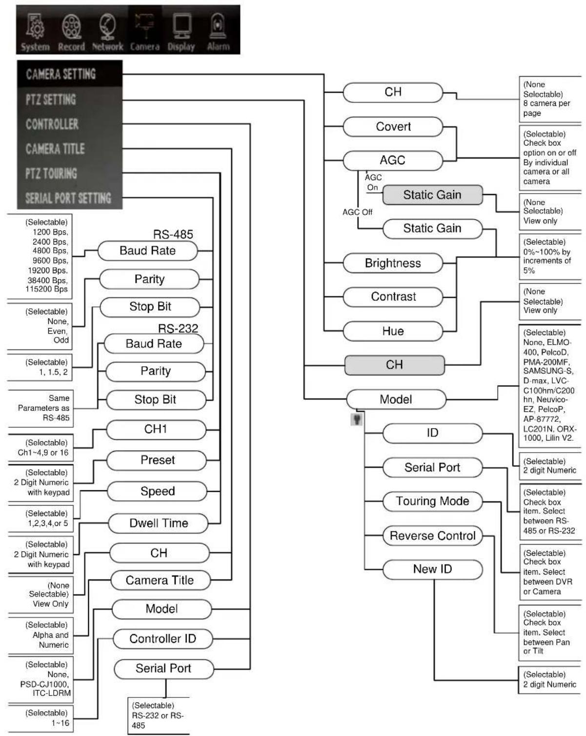
flowchart
graph TD
    A["CAMERA SETTING"] --> B["PTZ SETTING"]
    A --> C["CONTROLLER"]
    A --> D["CAMERA TITLE"]
    A --> E["PTZ TOURING"]
    A --> F["SERIAL PORT SETTING"]

    B --> G["RS-485 Baud Rate"]
    B --> H["Parity"]
    B --> I["Stop Bit"]
    B --> J["RS-232 Baud Rate"]
    B --> K["Parity"]
    B --> L["Stop Bit"]
    B --> M["CH1"]
    B --> N["Preset"]
    B --> O["Speed"]
    B --> P["Dwell Time"]
    B --> Q["CH"]
    B --> R["Camera Title"]
    B --> S["Model"]
    B --> T["Controller ID"]
    B --> U["Serial Port"]

    C --> V["CH"]
    C --> W["Covert"]
    C --> X["AGC"]
    X --> Y["Static Gain"]
    X --> Z["Static Gain"]
    X --> AA["Brightness"]
    X --> AB["Contrast"]
    X --> AC["Hue"]
    X --> AD["CH"]
    X --> AE["Model"]

    V --> AF["(None Selectable) 8 camera per page"]

    W --> AG["(Selectable) Check box option on or off By individual camera or all camera"]

    X --> AH["(None Selectable) View only"]

    Y --> AI["(Selectable) 0%~100% by increments of 5%"]

    Z --> AJ["(Selectable) None, ELMO-400, PelcoD, PMA-200MF, SAMSUNG-S, D-max, LVC-C100hm/C200 hn, Neuvico-EZ, PelcoP, AP-87772, LC201N, ORX-1000, Lilin V2."]

    AA --> AK["(Selectable) 2 digit Numeric"]

    AB --> AL["(Selectable) Check box item. Select between RS-485 or RS-232"]

    AC --> AM["(Selectable) Check box item. Select between DVR or Camera"]

    AD --> AN["(Selectable) Check box item. Select between Pan or Tilt"]

    AE --> AO["(Selectable) 2 digit Numeric"]

    F --> AP["(Selectable) RS-232 or RS-485"]

    G --> AQ["(Selectable) 1200 Bps, 2400 Bps, 4800 Bps, 9600 Bps, 19200 Bps, 38400 Bps, 115200 Bps"]

    H --> AR["(Selectable) None, Even, Odd"]

    I --> AS["(Selectable) 1, 1.5, 2"]

    J --> AT["(Selectable) No, Even, Odd"]

    K --> AU["(Selectable) No, Even, Odd"]

    L --> AV["(Selectable) No, Even, Odd"]

    M --> AW["(Selectable) No, Even, Odd"]

    N --> AX["(Selectable) No, Even, Odd"]

    O --> AY["(Selectable) 2 Digit Numeric with keypad"]

    P --> AZ["(Selectable) 1, 2, 3, 4, or 5"]

    Q --> BA["(Selectable) 2 Digit Numeric with keypad"]

    R --> BB["(None Selectable) View Only"]

    S --> BC["(Selectable) Alpha and Numeric"]

    T --> BD["(Selectable) None, PSD-CJ1000, ITC-LDRM"]

    U --> BE["(Selectable) 1~16"]

    V --> BF["(None Selectable)"]
    V --> BG[(Selectable) Selectable)
    V --> BH[(Selectable) Selectable)
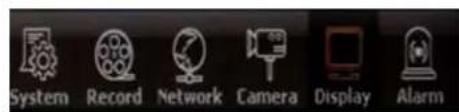
5. The "Display" Branch
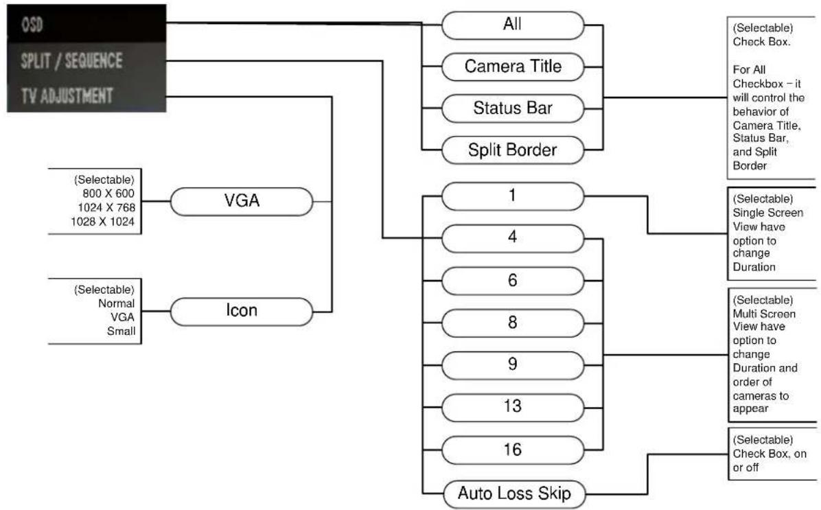
flowchart
graph TD
    A["OSD"] --> B["VGA"]
    C["SPLIT / SEQUENCE"] --> B
    D["TV ADJUSTMENT"] --> B
    E["(Selectable) 800 X 600\n1024 X 768\n1028 X 1024"] --> B
    F["(Selectable) Normal VGA Small"] --> G["Icon"]
    B --> H["All"]
    B --> I["Camera Title"]
    B --> J["Status Bar"]
    B --> K["Split Border"]
    G --> L["1"]
    G --> M["4"]
    G --> N["6"]
    G --> O["8"]
    G --> P["9"]
    G --> Q["13"]
    G --> R["16"]
    G --> S["Auto Loss Skip"]
    H --> T["(Selectable) Check Box. For All Checkbox – it will control the behavior of Camera Title, Status Bar, and Split Border"]
    I --> U["(Selectable) Single Screen View have option to change Duration"]
    J --> V["(Selectable) Multi Screen View have option to change Duration and order of cameras to appear"]
    K --> W["(Selectable) Check Box, on or off"]
- The "Alarm" Branch

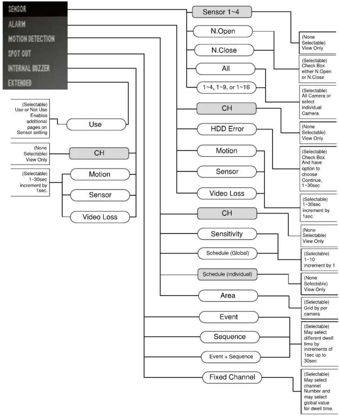
flowchart
graph TD
    A["SENSOR"] --> B["Use"]
    A --> C["CH"]
    A --> D["Motion"]
    A --> E["Sensor"]
    A --> F["Video Loss"]
    B --> G["Sensor 1~4"]
    C --> H["HDD Error"]
    D --> I["Sensor"]
    E --> J["Video Loss"]
    F --> K["CH"]
    G --> L["N.Open"]
    G --> M["N.Close"]
    G --> N["All"]
    G --> O["1~4, 1~9, or 1~16"]
    H --> P["(Selectable) Selectable) View Only"]
    H --> Q["(Selectable) Check Box either N.Open or N.Close"]
    H --> R["(Selectable) All Camera or select individual Camera"]
    I --> S["(Selectable) Check Box And have option to choose Continue, 1~30sec"]
    J --> T["(Selectable) 1~30sec increment by 1sec."]
    K --> U["(Selectable) Selectable) View Only"]
    K --> V["(Selectable) Selectable) View Only"]
    L --> W["Sensitivity"]
    M --> X["Schedule (Global)"]
    N --> Y["Schedule (individual)"]
    O --> Z["Area"]
    P --> AA["(Selectable) Grid by por camera"]
    Q --> AB["(Selectable) May select different dwell time by increments of 1sec up to 30sec"]
    R --> AC["(Selectable) May select channel Number and may select global value for dwell time."]
    S --> AD["(Selectable) Selectable) View Only"]
    T --> AE["(Selectable) Selectable) View Only"]
    U --> AF["(Selectable) Selectable) View Only"]
    V --> AG["(Selectable) Selectable) View Only"]
    W --> AH["(Selectable) 1~10 increment by 1"]
    X --> AI["(Selectable) 1~30sec increment by 1sec."]
Chapter 6. The "Search" Root Menu Item
1. The "Calendar" Search Branch
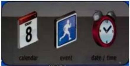

2. The "Event" Search Branch


flowchart
graph TD
    A["Event Selection"] --> B["All"]
    A --> C["1~16"]
    A --> D["Month"]
    A --> E["Day"]
    A --> F["Year"]
    A --> G["Type of Event"]
    A --> H["Search"]
    A --> I["Date Range"]
    A --> J["Disk Selection"]
    A --> K["Change Pages"]
    A --> L["Event List"]
    B --> M["(Selectable) Choose all or individual camera"]
    C --> N["(Selectable) 1~12"]
    D --> O["(Selectable) 1~28,29,30,31"]
    E --> P["(Selectable) Increase or decrease"]
    G --> Q["(Selectable all items, individual or none) Motion Video Loss Sensor System"]
    J --> R["(Selectable) Click Only"]
    K --> S["(None Selectable) View Only"]
    L --> T["(Selectable) Check One Only"]
    L --> U["(Selectable) Click Only"]
Chapter 6. The "Search" Root Menu Item
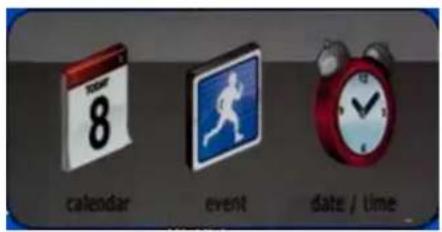
3. The "Date / Time" Search Branch
3. The "Date / Time" Search Branch

Chapter 7. The "Backup" Root Menu Item
- Calendar, Quick and List Branch
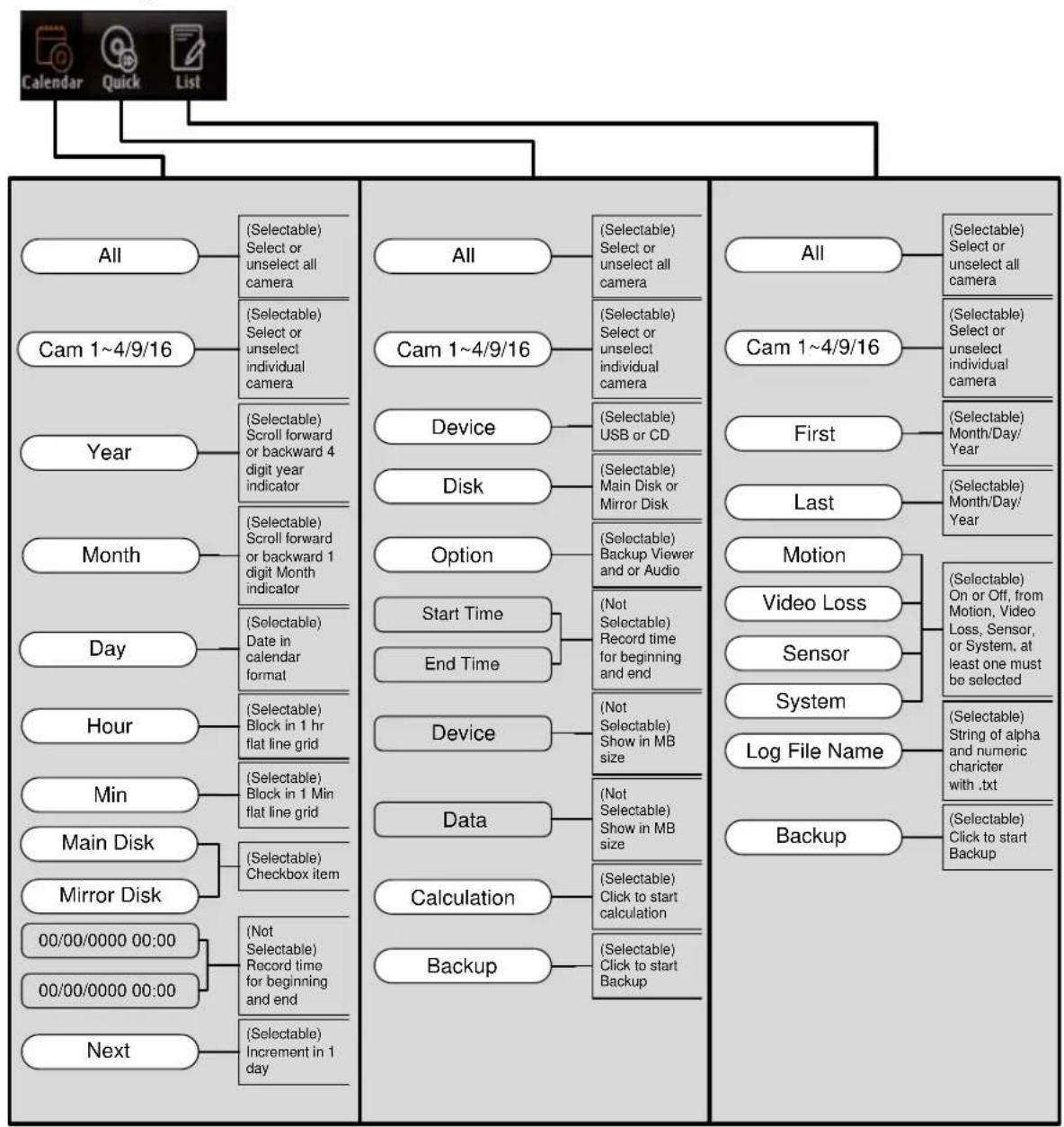
flowchart
graph TD
    A["All"] --> B["(Selectable) Select or unselect all camera"]
    C["Cam 1~4/9/16"] --> D["(Selectable) Select or unselect individual camera"]
    E["Year"] --> F["(Selectable) Scroll forward or backward 4 digit year indicator"]
    G["Month"] --> H["(Selectable) Scroll forward or backward 1 digit Month indicator"]
    I["Day"] --> J["(Selectable) Date in calendar format"]
    K["Hour"] --> L["(Selectable) Block in 1 hr flat line grid"]
    M["Min"] --> N["(Selectable) Block in 1 Min flat line grid"]
    O["Main Disk"] --> P["(Selectable) Checkbox item"]
    Q["Mirror Disk"] --> R["(Not Selectable) Record time for beginning and end"]
    S["00/00/0000 00:00"] --> T["(Not Selectable) Record time for beginning and end"]
    U["00/00/0000 00:00"] --> V["(Not Selectable) Record time for beginning and end"]
    W["Next"] --> X["(Selectable) Increment in 1 day"]

    Y["All"] --> Z["(Selectable) Select or unselect all camera"]
    AA["Cam 1~4/9/16"] --> AB["(Selectable) Select or unselect individual camera"]
    AC["Device"] --> AD["(Selectable) USB or CD"]
    AE["Disk"] --> AF["(Selectable) Main Disk or Mirror Disk"]
    AG["Option"] --> AH["(Selectable) Backup Viewer and or Audio"]
    AI["Start Time"] --> AJ["(Not Selectable) Record time for beginning and end"]
    AK["End Time"] --> AL["(Not Selectable) Show in MB size"]
    AM["Device"] --> AN["(Not Selectable) Show in MB size"]
    AO["Data"] --> AP["(Not Selectable) Show in MB size"]
    AQ["Calculation"] --> AR["(Selectable) Click to start calculation"]
    AS["Backup"] --> AT["(Selectable) Click to start Backup"]

    Y --> AU["All"]
    AA --> AV["Cam 1~4/9/16"]
    AC --> AW["First"]
    AC --> AX["Last"]
    Y --> AY["Motion"]
    Y --> AZ["Video Loss"]
    Y --> BA["Sensor"]
    Y --> BB["System"]
    Y --> BC["Log File Name"]
    Y --> BD["Backup"]

    style A fill:#f9f,stroke:#333
    style C fill:#f9f,stroke:#333
    style E fill:#f9f,stroke:#333
    style G fill:#f9f,stroke:#333
    style I fill:#f9f,stroke:#333
    style K fill:#f9f,stroke:#333
    style M fill:#f9f,stroke:#333
    style O fill:#f9f,stroke:#333
    style Q fill:#f9f,stroke:#333
    style S fill:#f9f,stroke:#333
    style U fill:#f9f,stroke:#333
    style X fill:#f9f,stroke:#333
    style Y fill:#f9f,stroke:#333
    style AC fill:#f9f,stroke:#333
    style AD fill:#f9f,stroke:#333
    style AF fill:#f9f,stroke:#333
    style AG fill:#f9f,stroke:#333
    style AH fill:#f9f,stroke:#333
    style AI fill:#f9f,stroke:#333
    style AJ fill:#f9f,stroke:#333
    style AK fill:#f9f,stroke:#333
    style AL fill:#f9f,stroke:#333
Chapter 8. The "ER", "PTZ", and "Sound" Root Menu Items
- Calendar, Quick and List Branch
Chapter 8. The "ER", "PTZ", and "Sound" Root Menu Items
The ER root menu item funcons as panic recording features and only have one functional buon which is the ER buon itself.
PTZ root menu item will invoke PTZ funcon on single channel view.
Sound root menu item will bring up a single page popup that shows audio o, audio channel 1\~4 to enable and disable and check box with Auto feature where sound input and output is operated by hardware associated for such exists that will be automatically utilized. See below Figure 57 Audio Popup.

Figure 57 Audio Popup
Chapter 9. Systems Secon In-Depth
1. INFORMATION GUI
Graphic User Interface (GUI) for INFORMATION secon under SYSTEM is as shown below.

The SYSTEM INFORMATION secon page indicates what type of language is being used, remote controller ID informaon, control for the mouse sensitivity, video standards MAC (media access control) address, webcode (special unique idener only given to our DVR units) and all versions of soware and hardware that makes up the DVR unit. This sec on is equivalent to "About" sec on of applica on program.
Language
There are 10 dierent languages available for the DVR unit. As language eld is toggled between English, Korean, Japanese, Russian, Italian, Romanian, Bulgarian, Lithuanian, French, and Spanish you will experience the change in GUI. We need to cauon that if language you do not understand is selected please reference this manual for the locaon where language item is located in system menu. For beer understanding of the layout of our GUI, refer to secon 1. The “System” Branch in chapter Chapter 5. The “System” Root Menu Item.
Remocon ID (Remote Controller ID)
This ID seng enables to control more than two DVRs with one remote controller. Order of conguraon is rst you need to select DVR to have ID that are not going to conict with other DVR(s).
Set the ID per each DVR and match the ID for use.
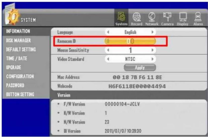
Figure 58 Remote Controller ID
The default value for the ID is "00". Change it to other value other than "00". Let's say that we change the remote controller ID to "02" and then exit out of the GUI menu and save. Then point the remote controller and press the red buon labeled ID.
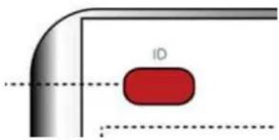
Figure 59 Remote Controller ID Buon on remote controller
You will see Figure 60 ID selector screen. Your ID selector screen should appear with DVR ID: 01 in our example (gure shows 00) and you must use the direconal buon on the remote to conjure larger number ID eld to 01 as well.

Figure 60 ID selector screen
Now you will have the ability to use that remote controller to operate this parcular DVR unit.
Also you may use two remote for two spate DVR let's say you con gure one remote to last sync with DVR ID of 01 and use the other remote only for DVR ID of 00 then these two remote now has dierent ID. Our remote controller has micro controller built in and it remembers the last ID that it was assigned. Therefore, our remote controllers have capability to be assigned ID numbers as well as DVR having spate ID numbers for remote controller.

Tow DVR with one remote controller

Tow DVR with two remote controller
Mouse Sensitivity
This feature enables user how responsive are the movement of the mouse can be when user is operating a mouse via the USB conncon provided either in front or back of the DVR unit. It only applies to the mouse sensitivity locally to the DVR not to the remote applicaon. Sensitivity seng has level 1\~3. Lowest level being most slow to 3 being the fastest.
Video Standard
There are two selectable standards for video NTSC or PAL. Reasons for two type of video standards are that some countries decided to use PAL or NTSC standard for television broadcast. In CCTV environment you must correspond to determine what type of cameras are being used and what type of display monitor is being used. Simple rule to remember is that you should matchup equipment with one uniform standard. If you resided in country that uses NTSC for broadcast and are using NTSC monitor, NTSC Camera then you must choose NTSC for video standards seng for DVR unit. Even if you reside in country that uses PAL standards some countries uses NTSC standard due to compatibility of equipments being used. So it is very critical that you identify what types of camera, and what type of monitor will be used for the DVR unit.
NTSC (Naonal Television System Commiee), PAL (Phase Alternang Line) are what these acronyms mean. NTSC standards are predominantly being used in North American countries, some South American country, and a PAL standard dominates the European countries, some South American countries such as Argenna, Uruguay, Brazil and many part of Asia with excepon to South Korea, Japan, and Philippines.
NTSC countries
| Canada | Japan | Puerto Rico |
| Chile | Mexico | South Korea |
| Costa Rica | Nicaragua | Taiwan |
| Cuba | Panama | U.S.A. |
| Dominican Republic | Peru | |
| Ecuador | Philippine |
Table 1 NTSC countries
MAC Address
As menoned before MAC (Media Access Control) addresses are unique to individual network card or NIC (Network Interface Card). They are represented in six groups of two hexadecimal digits. These address are somemes referred as physical address or hardware address as well. Importance of MAC address for our DVR is when users need to provide this informaon to network administrator. Many reasons your network administrator will need to have MAC address but one most important reason may be for providing adequate rules for organiza on's rewall con gura on or (and) for proper port forwarding applicaon. Oen mes MAC address are used to create special network rules and are someme given special privilege in network using MAC address. In this manual we would only discuss applied needs of MAC address pertaining to our DVR unit. For further informaon regarding MAC address please refer to guides that explain basic principles of Ethernet networking.
Webcode
This also is unique idener that our DVR has mainly funcons as special idener that is used in DDNS service. Our DVR unit has very easy to use DDNS features and this Webcode is very important part of identifying DVR unit in networking and communicaon.
Versions
In this secon there are notaons for F/W Version, H/W Version, N/W Version, and UI Version. They are Firmware, Hardware, Network, User Interface version informaon. These informaon are crical informaon when troublesomeong the DVR unit or to service the DVR unit. Firmware versions indicate type of memory resident soware informaon that is installed in the DVR unit. Hardware version indicates physical equipment versions that have component dierences. Netware versions indicate type of NIC cards and network controllers and UI is GUI versions.
2. DISK MANAGER GUI
Below is the GUI for the DISK MANAGER secon.

Figure 61 Disk Manager GUI
In this secon where opons for HDD there are opons to see condion of all the HDD installed in the DVR unit as well as performing format, see HDD error and current condion of HDD using S.M.A.R.T.
There are also seconds showing other drives that are present. Disk 1 is primary drive that must be installed to have proper operation of DVR unit.
Please check and perform a format operaon if DVR unit is not recording, there may be HDD installed but if HDD is not formaed then recording will not occur. Please perform format operaon any me when you do a HDD upgrade.
Adding, installing HDD and other drives
Here below illustrate how HDD must be installed in event of HDD upgrade or introducing secondary HDD.

Figure 62 HDD Installaon
When you mount a single hard drive, mount it to "Master HDD" as described in the picture above and connect the power. Then, connect the SATA cable to the main board "HDD1."
When you'd like to mount two HDDs, install "Slave HDD" as described in the picture above, connect the power. And then, connect SATA cable to the main board "HDD2."
Installing ODD (Opcal Disk Drive)
Alternatively you may have HDD 1 and Opcal Disk Drive.
Important reminder is to make sure aer inserng ODD, check to see recording in HDD 2 is not enabled and make sure that ODD is visible in disk manager secon..
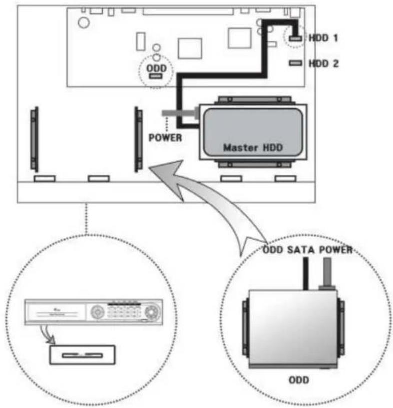
flowchart
graph TD
    A["Master HDD"] -->|ODD| B["HDD 1"]
    A -->|ODD| C["HDD 2"]
    D["Power"] --> A
    E["ODD SATA POWER"] --> F["ODD"]
Detach the front panel from the unit and also detach the ODD cover.
Mount the ODD to its bracket and connect the power. Then, connect the SATA cable to the ODD port.

Figure 63 HDD 1 and HDD 2 example
Set the rst HDD connected to "HDD1" in the system.

Figure 64 Disk 1 Conguraon
- Set Main Disk or Mirror Disk.
Main Disk or Mirror Disk opon will be available.
Main Disk is used for single disk operaon or 2 HDD that will use its maximum volume capacity.
At least HDD1 must be set to Main Disk (Single HDD).
With HDD1 and HDD2 installed both HDD1 and HDD2 must be formed upon 1st me operation.
Mirror Disk opon must be chosen if HDD 1 is replicated to HDD 2.
When Mirror Disk opon is set and has data corrupon or HDD failure HDD2 has replicated informaon of HDD1.
- Format: Format the HDD
HDD must be formaed when new disk is introduced.
HDD must be formaed when disk is from dierent DVR unit.
HDD format is recommended when disk is pulled out and reintroduced to DVR unit.
- Capacity: Used capacity/ Total HDD capacity (Ex : 0 / 238080 MB)
Capacity indicator depicts capacity in percentage and actual les size in mega byte.
CD / DVD RW
If the ODD is mounted, V(Check) is displayed. And if not, "∅" is displayed.
CD / DVD RW

Overwrite
When the enre HDD volume is consumed, the saved data will be erased as much as new data entered. (V: Overwrite, : No overwrite)
Overwrite


Auto Delete
Maintain the data during the designated period while automacally deleng the data saved previously. (Selecon Range : Not use, Able to set up to 120 days)
Auto Delete

030 day
Error List
When there is an error for the HDD such as Read, Write, Connecon status and HDD recognition, the date is saved. You can select the Delete buon to erase the data.
Error List
Chapter 9. Systems Section In-Depth
2. DISK MANAGER GUI
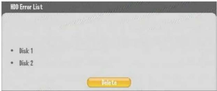
S.M.A.R.T(Disk Management)
Display the HDD temperature. If the temperature rises to the designated degree, DVR omits audible alert as well as creates an event that may be need.
Temperature seng range: Not use, 10'C, 20'C, 30'C, 40'C, 50'C, 60'C, 70'C, 80'C, 90'C

3. DEFAULT SETTING GUI
If you ever need to revert to a factory default values of some or all informaon you have an opon to choose between "Default Se ng" or "Factory Default" bu on.
Dierences between two buons are that;
Default Seng : Reset all the sengs except the crical sengs such as Network, Password. in the menu to their default values.
Factory Seng : Reset all the sengs in the menu to their default values.

Figure 65 Default Seng
When these default sengs are required are when you perform a hardware upgrade or rmware upgrade. Somemes these upgrades are not required to have default sengs applied but some occasions it will be best to perform it and reconfigure the parameters according to guidelines of support representave or technician.
Default seng operaon are recommended on following situaon;
- Operang the device for the 1st me. (even though manufacturer may have best guessed possible user environment it is best pracce to revert to default and start conguring to users environment)
- When products is moved to dierent facility or sent to dierent me zone.
- When mulple users access the DVR unit and have administrator rights among the users where you are not sure of the changes implemented on the DVR unit.
4. TIME / DATE GUI
In this secon of GUI page you can perform operaon to change me and date. It is recommended that you perform this operaon when you rst receive your unit for deployment and is installed in physical locaon of DVR unit placement. Having the proper me and date informa on is very cri cal when DVR's recorded informaon be presented as evidence to event recorded on the device. You must also be mindful of each regional rules of day light savings me conguraon.

Figure 66 Time Date GUI
Conguring Year/Month/Day
You can select the display type per country.

• ASIA : Year/ Month/ Day → (Ex) 2006/05/31
• US : Month/ Date/ Year → (Ex) 05/31/2006
• EURO : Date/ Month/ Year → (Ex) 31/05/2006
Conguring Date & Time
Set the current date and me.
Set the me and press "Apply". And then check the popup message and select "Yes."

Figure 67 Conrmaon of date and me change
This message in Figure 67 Conrmaon of date and me change appears when there exist some data in HDD that has dierent me than what you are changing to.
Consequences are;
- If you change the time from 3pm to 4pm, when searching, the 4pm video is played aer the 3pm video is played.
- If you change the me from 3pm to 2pm, when searching, the 2pm video is played a er the 3pm video is played.
Conguring Daylight Saving Time
You can set me to one hour before for certain period of me in the summer
(example)

Figure 68 Daylight Saving Time
Above seng is started from 12:00, Sunday of the last week in July and ended at 00:00,
Monday of the 3th week in August.
Conguring Time Server
It is used to keep the system me constant. It synchronizes the me through the selected me interval and the server.

• Time Server : Enter the me server URL or IP
- Sync Cycle : Set the sync cycle with the me server
• GMT : Set the standard me zone
• Test : Check the operaon status of the me server
4. UPGRADE GUI
In this secon of GUI page, you will need to introduce the USB media with valid rmware update le and this GUI will show le name similar to Figure 69 UPGRAD GUI.
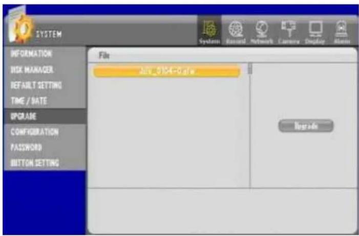
Figure 69 UPGRAD GUI
Save the rmware to the USB Memory Sck and insert it into the USB port of a DVR. Then the le list stored in the memory sck is displayed. Select the relevant rmware le and click the Upgrade tap.

Figure 70 Firmware to USB memory
It may take a minute or a minute & 30 seconds depending on the rmware. Please wait unl reboong is nished. Do not unplug or take out the USB memory sick during the upgrade. Otherwise, it could be the cause of the product failure.
You can archive the system conguraon le to USB memory sick or restore the previous system conguraon from the archived le.

Figure 71 Conguraon GUI
Conguraon Download
Insert the USB memory sck to DVR unit and conguraon le may be down save to USB memory sck.
You will se conguraon le similar to below Figure 72 Conguraon Backup Buon.

Figure 72 Conguraon Backup Buon
Then make sure give enough me to have conguraon le to be wrien to USB memory sck.

Figure 73 Save conguraon le to USB memory
Now as seen on Figure 73 Save conguraon le to USB memory conguraon le.
Conguraon Upload
Take the USB memory sck to DVR unit, you should have already prepared a memory sck with proper conguraon on memory sck. Then apply the upload as you see the upload secon appears with le name.

Figure 74 Memory Sck with conguraon le
6. PASSWORD GUI
This GUI secon you can change details for user informaon, login, authority, and network camera view authority. There are 8 users accounts in our DVR, they are “admin”, “user1”, “user2”, “user3”, “user4”, “user5”, “user6”, and “user7”. They all have default password of “11111111”, and are strongly recommended to be changed. These login accounts are needed when you remotely connect to the DVR and as well as performing password protected funcon such as HDD format, user authority and other crical operaons for DVR.

Figure 75 PASSWORD GUI
Conguring User ID
You can register as many as eight system users and they are "admin", "user1", "user2", "user3", "user4", "user5", "user6", and "user7".

This is the list of IDs being registered. If you want to edit, select the list and you can move on to "change" menu.
Modifying User Informaon
You can modify informaon of selected ID (account).

Figure 76 Modify Secon for User Informaon
- ID : Displays ID selected through the list. If you want to change, select and enter through virtual keyboard. You can enter as many as eight character alphanumeric value.
-
User Group: The authority is allocated per each group. They may be assigned to users, so it will be easier to conjure and easier to group.
-
Admin : Able to use all funcons.
- Power User : Able to use the setup, search and backup funcon.
- User: A user can select the authority range.
- Password: Enter up to eight numbers. 1111111 is the default password.
Conguring User Authority
Select the authorities for the selected User ID.

Figure 77 User Authority
Chapter 9. Systems Section In-Depth
6. PASSWORD GUI
• All : Allows full authority.
- Con gura on : Allows to set the DVR.
- Search : Allows to search.
- Back up : Allows to backup.
- Hard Disk : Allows to set the HDD such as Overwrite, Auto Delete, etc.
- Record Key: Allows to operate the Schedule Record or Emergency Record.
- PTZ Control : Allows to control the PTZ.
Conguring Network Covert
When you choose camera to be hidden, selected camera images are not displayed when it is monitored remotely.

Figure 78 Network Covert User Conguraon
You can use the rst ck box for "Apply All" or "Cancel All".
7. BUTTON SETTING GUI
Buon seng GUI is used to control the audible beep, autokey lock and emergency lock.

Figure 79 BUTTON SETTING GUI
Conguraon of audible beep
If it is selected, the DVR beeps on every buon press in the front panel.
(: Beep, : No Beep)
Conguraon of Auto Key Lock
If the selected me is passed, the system is locked automacally.
Even if the system is locked, you can select the channel, split screen and sequence viewing. But you have to log on to the system for the operaon of other funcons.

(If the system is locked, the Icon is changed like the picture above)
Conguraon of Emergency Lock
This setting locks the emergency recording so that the emergency recording isn't available. In case a user keeps the emergency recording on, it could overuse the HDD or overwrite the existing data. So, you can lock the emergency recording to prevent the problem.
( √ : Emergency recording isn't available, ⊖ : Emergency recording is available )
Chapter 10. Record Secon In-Depth
In this sec on we will cover all aspects of record con gura on, and how it e ccts the DVR's performance, storage capacity, recorded image quality and frames per second of recorded video.
1. Compression, Resoluon, Quality, and Speed of Video
Video Compression
This DVR is using the H.264 compression, compression used to compact the size of the video recording that are save to the HDD. The H.264 compression is currently being used to stream HD video in broadcast industry and is being widely accepted as industry standard in compression. Compare to older compression types, H.264 compression uses more complex algorithms to compress video therefore even the TCP/IP streaming videos are adapting this H.264 compression. Compression opon is not selectable, yet it is important to understand that this DVR is using the best compression available at the me of product creation.
Video Resoluon
Our DVR currently supports 3 types of video resolution possible for recording and they are resolution measuring at 720 pixels by 480 pixels, 720 pixels by 240 pixels, and 360 pixels by 240 pixels in NTSC format. In PAL format they are 720 pixels by 576 pixels, 720 pixels by 288 pixels, and 360 pixels by 288 pixels. Oen they are referenced and marked 720X480 or D1 resolution, 720X240 or 2CIF resolution, 360X240 or CIF resolution for NTSC. Respectively in PAL standard they are referenced as 720X576 or D1 resolution, 720X288 or 2CIF resolution, 360X288 or CIF resolution.
There are two selectable standards for video NTSC or PAL. Reasons for two type of video standards are that some countries decided to use PAL or NTSC standard for television broadcast. In CCTV environment you must correspond to determine what type of cameras are being used and what type of display monitor is being used. Simple rule to remember is that you should matchup equipment with one uniform standard. If you resided in country that uses NTSC for broadcast and are using NTSC monitor, NTSC Camera then you must choose NTSC for video standards seng for DVR unit. Even if you reside in country that uses PAL standards some countries uses NTSC standard due to compatibility of equipments being used. So it is very critical that you identify what types of camera, and what type of monitor will be used for the DVR unit.
Chapter 10. Record Section In-Depth
1. Compression, Resolution, Quality, and Speed of Video
Video Quality
On our DVR there are 5 levels of video quality. They are marked "Lowest", "Low", "Normal", "High" and "Highest". Since all H.264 images are compressed from its original images this 5 step of level dictates how much compression will be applied to each individual images being recorded. If you are conguring "Lowest" se ng, then you are telling the DVR to use high compression level for each individual image. That means that high compression will yield the smallest data size but will provide the lowest detailed images among 5 levels of video quality. Here are reference les sizes for each image quality in terms of NTSC resoluon. These gures may dier depending on complexity of background and paerns being watched by each individual camera because H.264 compression's performances also are impacted between complex and simple paerns.
| NTSC Resoluon | “Lowest” se ng per image in kilo byte | “Low” se ng per image in kilo byte | “Normal” se ng per image in kilo byte | “High” se ng per image in kilo byte | “Highest” se ng per image in kilo byte |
| 720X480 (D1) | 4.34 kb | 5.50 kb | 6.65 kb | 8.90 kb | 11.15 kb |
| 720X240 (2CIF) | 2.00 kb | 2.70 kb | 3.36 kb | 4.10 kb | 4.66 kb |
| 360X240 (CIF) | 1.12 kb | 1.45 kb | 1.71 kb | 2.30 kb | 2.83 kb |
Table 2 Data size - Image Quality by Resoluon
It is recommended that you try all possible resoluon seng and image quality sengs before nding most proper image quality before comming recording seng. Be cauous, as higher the image quality seng larger the le size, ulmately shortening number of days of recording.
Speed of Video
Speed of images are represented in frames per second calculaon. Our DVR may record video in 1, 2, 3, 5, 6, 7.5, 10, 15 and 30 frames per second conguraon. If recording is congured to be set on 30fps that represents that for every second there will be 30 images recorded. In our DVR there are some limitaons on how much frames may be recorded by channel type of our DVR.
- For 4 channel DVR;
You may have all 4 cameras recording in 1, 2, 3, 5, 6, 7.5, 10, 15 and 30 frames per second at 360X240, 720X240, and 720X480 resoluon. - For 9 channel DVR;
You can have 360X240 recording in 1, 2, 3, 5, 6, 7.5, 10, 15 and 30 frames per second.
You can have 720X240 recording in 1, 2, 3, 5, 6, 7.5, 10, and 15 frames per second all across or have 8 cameras recording at 1, 2, 3, 5, 6, 7.5, 10, 15 and 30 frames per second.
You can have 720X480 recording in 1, 2, 3, 5, 6, 7.5, and 10 frames per second all across or have 8 cameras recording at 1, 2, 3, 5, 6, 7.5, 10, and 15 frames per second.
- For 16 channel DVR;
You can have 360X240 recording in 1, 2, 3, 5, 6, 7.5, 10, 15 and 30 frames per second.
You can have 720X240 recording in 1, 2, 3, 5, 6, 7.5, 10, and 15 frames per second.
Chapter 10. Record Section In-Depth
1. Compression, Resolution, Quality, and Speed of Video
You can have 720X480 recording in 1, 2, 3, 5, 6, and 7.5 frames per second.
- For 16 channel DVR combinaon example;
You can have 1 camera recording at 720X480 recording 15 frames per second.
You can have 2 cameras recording 720X240 15 frames per second.
You can have 2 cameras recording 360X240 15 frames per second.
You can have rest of the camera 360X240 recording 15 frames per second.
As you could see from the above example you may mix and match conguraon to obtain best scenario applicable for your situaon.
2. Calculang Storage Required
As you have had an opportunity to review compression, resoluon, quality, and speed of video, all these factors are needed to intelligently calculate proper storage amount needed for each DVR unit or best congure each video. Here is a simple mathemacal formula for your convenience.
HDD Size Per Day by each Camera = number of frames per second X number of seconds in a day (1Day = 60X60X24) X size of image in bytes (see Table 2 Data size - Image Quality by Resoluon on page 92).
With above formula here are some reference gures
| Resoluon | 1 camera @Lowest @30fps @1 hour | 1 camera @Low @30fps @1 hour | 1 camera @Normal@30fps @1 hour | 1 camera @High@30fps @1 hour | 1 camera @Highest@30fps @1 hour |
| 360X240 | 119 MB | 153 MB | 181 MB | 243 MB | 299 MB |
| 720X240 | 211 MB | 285 MB | 355 MB | 433 MB | 492 MB |
| 720X480 | 485 MB | 581 MB | 702 MB | 939 MB | 1176 MB |
Table 3 30fps by one camera each hour
| Resoluon | 4 camera @Lowest @30fps @500 GB HDD | 4 camera @Low @30fps @500 GB HDD | 4 camera @Normal@30fps @500 GB HDD | 4 camera @High@30fps @500 GB HDD | 4 camera @Highest@30fps @500 GB HDD |
| 360X240 | 45 days 3 hrs | 34 days 21 hrs | 29 days 13 hrs | 21 days 23 hrs | 17 days 20 hrs |
| 720X240 | 25 days 6 hrs | 18 days 17 hrs | 15 days 1 hrs | 12 days 8 hrs | 10 days 20 hrs |
| 720X480 | 11 days 15 hrs | 9 days 4 hrs | 7 days 14 hrs | 5 days 16 hrs | 4 days 12 hrs |
Table 4 4ch DVR 500GB by each resoluon
| Resoluon | 9 camera @Lowest @500 GB HDD | 9 camera @Low @500 GB HDD | 9 camera @Normal@500 GB HDD | 9 camera @High@500 GB HDD | 9 camera @Highest@500 GB HDD |
| 360X240 @ 30fps | 20 days 1 hrs | 15 days 11 hrs | 13 days 3 hrs | 9 days 18 hrs | 7 days 22 hrs |
| 720X240 @ 15 fps | 22 days 6 hrs | 16 days 15 hrs | 13 days 9 hrs | 10 days 23 hrs | 9 days 15 hrs |
| 720X480 @ 10 fps | 15 days 12 hrs | 12 days 6 hrs | 10 days 3 hrs | 7 days 13 hrs | 6 days 1 hrs |
Table 5 9ch DVR 500GB by Resoluon with max possible frame rate
| Resoluon | 16 camera @ Lowest @ 500 GB HDD | 16 camera @ Low @ 500 GB HDD | 16 camera @ Normal@ 500 GB HDD | 16 camera @ High@ 500 GB HDD | 16 camera @ Highest@ 500 GB HDD |
| 360X240 @ 30fps | 11 days 6 hrs | 8 days 17 hrs | 7 days 9 hrs | 5 days 11 hrs | 4 days 11 hrs |
| 720X240 @ 15 fps | 12 days 15 hrs | 9 days 8 hrs | 7 days 14 hrs | 6 days 4 hrs | 5 days 10 hrs |
| 720X480 @ 7.5 fps | 11 days 15 hrs | 9 days 4 hrs | 7 days 12 hrs | 5 days 16 hrs | 4 days 12 hrs |
Table 6 16ch DVR 500GB by Resoluon with max possible frame rate
These tables represent relave calculaon at connuous recording conguraon.
4 Channel DVR Storage Reference Chart
Here are some examples of easy to reference chart for 4ch DVR. Moon recording results may vary depending on actual circumstances of how DVR is program to record. Such impacing variables are how much moon will each camera will be recording and how sensitive moon detection areas are.
| Resoluon | Lowest | Low | Normal | High | Highest |
| 500 Giga Byte / Recording Connuous | |||||
| 360X240 @ 30 fps | 45 days 3 hrs | 34 days 20 hrs | 29 days 13 hrs | 21 days 23 hrs | 17 days 20 hrs |
| 720X240 @ 30 fps | 25 days 6 hrs | 18 days 17 hrs | 15 days 1 hrs | 12 days 8 hrs | 10 days 20 hrs |
| 720X480 @ 30 fps | 11 days 15 hrs | 9 days 4 hrs | 7 days 14 hrs | 5 days 16 hrs | 4 days 12 hrs |
| 500 Giga Byte / On Moon (Considering there is only 35% of recording due to moon) | |||||
| 360X240 @ 30 fps | 128 days 23 hrs | 99 days 15 hrs | 84 days 11 hrs | 62 days 19 hrs | 51 days 1 hrs |
| 720X240 @ 30 fps | 72 days 5 hrs | 53 days 12 hrs | 42 days 23 hrs | 35 days 5 hrs | 31 days 0 hrs |
| 720X480 @ 30 fps | 33 days 6 hrs | 26 days 6 hrs | 21 days 17 hrs | 16 days 5 hrs | 12 days 22 hrs |
| 1 Tera Byte / Recording Connuous | |||||
| 360X240 @ 30 fps | 92 days 11 hrs | 71 days 10 hrs | 60 days 13 hrs | 45 days 0 hrs | 36 days 14 hrs |
| 720X240 @ 30 fps | 51 days 18 hrs | 38 days 8 hrs | 30 days 19 hrs | 25 days 6 hrs | 22 days 5 hrs |
| 720X480 @ 30 fps | 23 days 20 hrs | 18 days 19 hrs | 15 days 13 hrs | 11 days 15 hrs | 9 days 6 hrs |
| 1 Tera Byte / On Moon (Considering there is only 35% of recording due to moon) | |||||
| 360X240 @ 30 fps | 264 days 4 hrs | 204 days 1 hrs | 173 days 0 hrs | 128 days 15 hrs | 104 days 13 hrs |
| 720X240 @ 30 fps | 147 days 22 hrs | 109 days 14 hrs | 88 days 1 hrs | 72 days 4 hrs | 63 days 11 hrs |
| 720X480 @ 30 fps | 68 days 4 hrs | 53 days 19 hrs | 44 days 11 hrs | 33 days 5 hrs | 26 days 12 hrs |
| 6 Tera Byte (2X 3TB HDD) / Recording Connuous | |||||
| 360X240 @ 30 fps | 554 days 19 hrs | 428 days 12 hrs | 363 days 9 hrs | 270 days 3 hrs | 219 days 13 hrs |
| 720X240 @ 30 fps | 310 days 16 hrs | 230 days 3 hrs | 184 days 22 hrs | 151 days 13 hrs | 133 days 8 hrs |
| 720X480 @ 30 fps | 143 days 4 hrs | 112 days 23 hrs | 93 days 10 hrs | 69 days 19 hrs | 55 days 17 hrs |
| 6 Tera Byte (2X 3TB HDD) / On Moon (Considering there is only 35% of recording due to moon) | |||||
| 360X240 @ 30fps | 1585 days 3 hrs | 1224 days 9 hrs | 1038 days 5 hrs | 771 days 21 hrs | 627 days 8 hrs |
| 720X240 @ 30 fps | 887 days 16 hrs | 657 days 13 hrs | 528 days 9 hrs | 433 days 0 hrs | 380 days 23 hrs |
| 720X480 @ 30 fps | 409 days 1 hrs | 322 days 19 hrs | 266 days 23 hrs | 199 days 11 hrs | 159 days 5 hrs |
Table 7 4ch DVR HDD Reference
*Above table is provided only as a guide not as guarantee.
9 Channel DVR Storage Reference Chart
Here are some examples of easy to reference chart for 9ch DVR. Special characterisc of 9 Channel DVR is that recording storages are shared between 9 channels not 8 channels, if it was 8 channels it may have been possible to have 30 fps all across even at 720X240. That is the reason for having this chart calculang its maximum frame rate at CIF 30fps, 2CIF 15fps and D1 at 10fps.
| Resoluon | Lowest | Low | Normal | High | Highest |
| 500 Giga Byte / Recording Connuous | |||||
| 360X240 @ 30 fps | 20 days 1 hrs | 15 days 11 hrs | 13 days 3 hrs | 9 days 18 hrs | 7 days 22 hrs |
| 720X240 @ 15 fps | 22 days 11 hrs | 16 days 15 hrs | 13 days 9 hrs | 10 days 23 hrs | 9 days 15 hrs |
| 720X480 @ 10 fps | 15 days 12 hrs | 12 days 6 hrs | 10 days 3 hrs | 7 days 13 hrs | 6 days 1 hrs |
| 500 Giga Byte / On Moon (Considering there is only 35% of recording due to moon) | |||||
| 360X240 @ 30 fps | 57 days 7 hrs | 44 days 6 hrs | 37 days 13 hrs | 27 days 22 hrs | 22 days 16 hrs |
| 720X240 @ 15 fps | 64 days 5 hrs | 47 days 13 hrs | 38 days 5 hrs | 31 days 7 hrs | 27 days 13 hrs |
| 720X480 @ 10 fps | 44 days 9 hrs | 35 days 0 hrs | 28 days 23 hrs | 21 days 15 hrs | 17 days 6 hrs |
| 1 Tera Byte / Recording Connuous | |||||
| 360X240 @ 30 fps | 41 days 2 hrs | 31 days 17 hrs | 26 days 22 hrs | 20 days 0 hrs | 16 days 6 hrs |
| 720X240 @ 15 fps | 46 days 0 hrs | 34 days 2 hrs | 27 days 9 hrs | 22 days 10 hrs | 19 days 18 hrs |
| 720X480 @ 10 fps | 31 days 19 hrs | 25 days 2 hrs | 20 days 18 hrs | 15 days 12 hrs | 12 days 9 hrs |
| 1 Tera Byte / On Moon (Considering there is only 35% of recording due to moon) | |||||
| 360X240 @ 30 fps | 117 days 10 hrs | 90 days 16 hrs | 76 days 21 hrs | 57 days 4 hrs | 46 days 11 hrs |
| 720X240 @ 15 fps | 131 days 12 hrs | 97 days 9 hrs | 78 days 6 hrs | 64 days 3 hrs | 56 days 10 hrs |
| 720X480 @ 10 fps | 90 days 21 hrs | 71 days 17 hrs | 59 days 7 hrs | 44 days 7 hrs | 35 days 9 hrs |
| 6 Tera Byte (2X 3TB HDD) / Recording Connuous | |||||
| 360X240 @ 30 fps | 246 days 13 hrs | 190 days 11 hrs | 161 days 12 hrs | 120 days 1 hrs | 97 days 14 hrs |
| 720X240 @ 15 fps | 276 days 4 hrs | 204 days 13 hrs | 164 days 9 hrs | 134 days 17 hrs | 118 days 12 hrs |
| 720X480 @ 10 fps | 190 days 21 hrs | 150 days 15 hrs | 124 days 14 hrs | 93 days 2 hrs | 74 days 7 hrs |
| 6 Tera Byte (2X 3TB HDD) / On Moon (Considering there is only 35% of recording due to moon) | |||||
| 360X240 @ 30 fps | 704 days 12 hrs | 544 days 4 hrs | 461 days 10 hrs | 343 days 1 hrs | 278 days 19 hrs |
| 720X240 @ 15 fps | 789 days 1 hrs | 584 days 11 hrs | 469 days 16 hrs | 384 days 21 hrs | 338 days 15 hrs |
| 720X480 @ 10 fps | 545 days 10 hrs | 430 days 9 hrs | 355 days 23 hrs | 265 days 23 hrs | 212 days 7 hrs |
Table 8 9ch DVR HDD reference
*Above table is provided only as a guide not as guarantee.
16 Channel DVR Storage Reference Chart
Here are some examples of easy to reference chart for 16ch DVR.
| Resoluon | Lowest | Low | Normal | High | Highest |
| 500 Giga Byte / Recording Connuous | |||||
| 360X240 @ 30 fps | 11 days 6 hrs | 8 days 17 hrs | 7 days 9 hrs | 5 days 11 hrs | 4 days 11 hrs |
| 720X240 @ 15 fps | 12 days 15 hrs | 9 days 8 hrs | 7 days 12 hrs | 6 days 4 hrs | 5 days 10 hrs |
| 720X480 @ 7.5 fps | 11 days 15 hrs | 9 days 4 hrs | 7 days 14 hrs | 5 days 16 hrs | 4 days 12 hrs |
| 500 Giga Byte / On Moon (Considering there is only 35% of recording due to moon) | |||||
| 360X240 @ 30 fps | 32 days 5 hrs | 24 days 21 hrs | 21 days 2 hrs | 15 days 16 hrs | 12 days 18 hrs |
| 720X240 @ 15 fps | 36 days 2 hrs | 26 days 18 hrs | 21 days 11 hrs | 17 days 14 hrs | 15 days 12 hrs |
| 720X480 @ 7.5 fps | 33 days 6 hrs | 26 days 6 hrs | 21 days 17 hrs | 16 days 5 hrs | 12 days 22 hrs |
| 1 Tera Byte / Recording Connuous | |||||
| 360X240 @ 30 fps | 23 days 2 hrs | 17 days 20 hrs | 15 days 3 hrs | 11 days 6 hrs | 9 days 3 hrs |
| 720X240 @ 15 fps | 25 days 21 hrs | 19 days 4 hrs | 15 days 9 hrs | 12 days 15 hrs | 11 days 2 hrs |
| 720X480 @ 7.5 fps | 23 days 20 hrs | 18 days 19 hrs | 15 days 13 hrs | 11 days 15 hrs | 9 days 6 hrs |
| 1 Tera Byte / On Moon (Considering there is only 35% of recording due to moon) | |||||
| 360X240 @ 30 fps | 66 days 1 hrs | 51 days 0 hrs | 43 days 6 hrs | 32 days 3 hrs | 26 days 3 hrs |
| 720X240 @ 15 fps | 73 days 23 hrs | 54 days 19 hrs | 44 days 0 hrs | 36 days 2 hrs | 31 days 17 hrs |
| 720X480 @ 7.5 fps | 68 days 4 hrs | 53 days 19 hrs | 44 days 11 hrs | 33 days 5 hrs | 26 days 12 hrs |
| 6 Tera Byte (2X 3TB HDD) / Recording Connuous | |||||
| 360X240 @ 30 fps | 138 days 16 hrs | 107 days 3 hrs | 90 days 20 hrs | 67 days 12 hrs | 54 days 21 hrs |
| 720X240 @ 15 fps | 155 days 8 hrs | 115 days 1 hrs | 92 days 11 hrs | 75 days 18 hrs | 66 days 16 hrs |
| 720X480 @ 7.5 fps | 143 days 4 hrs | 112 days 23 hrs | 93 days 10 hrs | 69 days 19 hrs | 55 days 17 hrs |
| 6 Tera Byte (2X 3TB HDD) / On Moon (Considering there is only 35% of recording due to moon) | |||||
| 360X240 @ 30 fps | 396 days 6 hrs | 306 days 2 hrs | 259 days 13 hrs | 192 days 23 hrs | 156 days 20 hrs |
| 720X240 @ 15 fps | 443 days 20 hrs | 328 days 18 hrs | 264 days 4 hrs | 216 days 12 hrs | 190 days 11 hrs |
| 720X480 @ 7.5 fps | 409 days 1 hrs | 322 days 19 hrs | 266 days 23 hrs | 199 days 11 hrs | 159 days 5 hrs |
Table 9 16ch DVR HDD reference
*Above table is provided only as a guide not as guarantee.
In this secon of GUI you can set the Resoluon, Frame and Event, etc. necessary to recording.
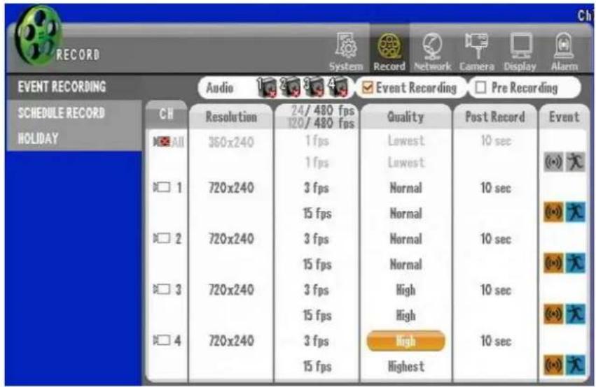
Conguring Pre Recording
When an event is triggered, this seng enables pre-recording around 1 to 5 seconds earlier. The pre-recording me is variable depending on the resoluon and frame seng. It would be longer if the low resoluon and frame are set. And the longest pre-recording me is 5 seconds.

Conguring Event Recording

This seng enables the event recording previously set when an event is triggered.
In the center of the EVENT RECORING GUI you will see the selectable area where you could choose camera, resoluon, fps, image quality, post record conguraon and event selector.
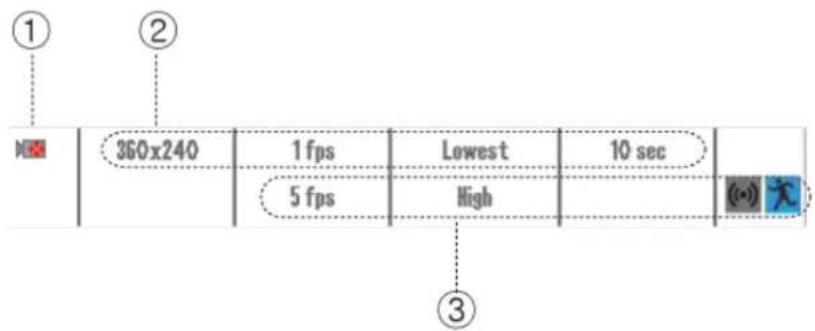
Figure 80 Recording Conguraon
① Camera selector (Global or individual)
Here in this camera icon you may select to use it or not use it. Below

(Not Used)

(Use)
② Resoluon, Speed (fps), Image quality, Post record conguraon
These selectable variables are possible opon conguraon for connuous recording setup. Here you can set the resoluon, frame, quality, post recording and audio independently.
- Resoluon: Select the size of recording image
Selecon ranges are 720X480, 720X240, 360X240 for NTSC and for PAL 720X576, 720X288, 360X288 - fps secon: Select how may frames per second that each camera will record.
If you see on the top of this secon column you will see a number marked similar to following indicaon 130/480 fps
It is representing that base of 480 fps all combined conguraon of fps selecon is within the boundaries of 480 fps or not. It is shown numerically and if combinaon of fps exceeds it will be marked in red number.
480 fps base means that if there are 16 cameras with 360X240 resoluon each recording at 30 fps then total fps capable of DVR is 480 fps combined. Then if one camera is set to 720X240 at 15 fps or
720X480 at 7.5 fps those are equivalent to 360X240 resoluons at 30 fps. So if you set 720X480 at 30 fps then it is equivalent to 360X240 at 120 fps so just on camera conguraon of 720X480 at 30 fps you will change the fps indicator to "120/480"
- Quality: Select the quality of recording image. There are ve quality levels to select. The higher the picture quality is, the bigger the data size is. (Lowest < Low < Normal < high < Highest)
- Post recording: Aer the event is triggered, set the period of me to connue the recording. (Range: From 10 to 300 seconds)
③Resoluon, Speed (fps), Image quality, Post record conguraon especially for those that are applied to event such as moon or alarm events. If an event is triggered in the middle of connuous recording, the recording mode is switched into event recording. And if the event is nished, it returns to the connuous recording mode.
- The setup for resolution, quality and post recording are same with the seng on Connuous recording
- Select the event: When an event is triggered, the event recording previously set is started.

(Unselected Sensor - Grey)

(Selected Sensor – Orange)

(Unselected Moon – Grey)

(Selected Moon – Blue)
4. SCHEDULE RECORDING GUI
You can schedule the recording me per me or channel or day of the week or holidays. As it also provide the event recording by the moon and sensor. When the schedule recording is in opera on, "SR" is displayed like the picture as below.

Figure 81 Main Display Indicaon
How to set : Call the Menu → Record → Schedule Record

Select the channel
Select the channel to record
Set the recording schedule
When scheduling, you can also select the recording mode such as Connue, Moon and Sensor, etc. You can schedule the recording mode by mouse dragging aer clicking the recording mode. Or you can select the recording mode by using the sequential change of the recording mode as the color changes per every single click.
Chapter 10. Record Section In-Depth
4. SCHEDULE RECORDING GUI
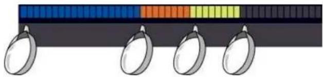
natural_image
Illustration of four metallic ring components with a color-coded scale bar (no text or symbols)
Moon: record when moon occurs

Sensor: record when sensor is in operaon

Moon or sensor: record when either of moon or sensor occurs

Connuaon: record regardless of event

Erase schedule

Erase all
Copy
Apply the same sengs to the other channel.
You can also apply the same seng values to the mulple channels.

(Not use)

(Use)
5. HOLIDAY GUI
You can set the recording for the holidays you designated.
How to set: Call the Menu → Record → Holiday
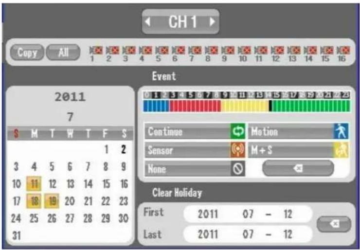
Figure 82 Holiday Scheduling GUI
Select the channel
Select the channel to apply the schedule
Select holidays
Select holidays on the calendar to have them marked with red color. Then, holiday recording is applied to the selected date.
Set the recording schedule
When scheduling, you can also select the recording mode such as Connue, Moon and Sensor, etc. You can schedule the recording mode by mouse dragging aer clicking the recording mode. Or you can select the recording mode by using the sequential change of the recording mode as the color changes per every single click.

natural_image
Illustration of four metallic objects with a color-coded bar above them (no text or symbols)Copy
Apply the same sengs to the other channel. You can also apply the same seng values to the mulple channels.

(Not use)

(Use)
Delete
Enter the rst and last date and then press Delete to remove the saved holidays within the range.

Chapter 11. Network Secon In-Depth
1. About Network Secon and Clients
The Network Sengs menu enables the user to congregate the DVR to be viewed, controlled, and maintained remotely by using the Remote Connecon Applicaon(s) (Included on the applicaon disk that came with your DVR):
- CMS (Central Management System – mul ple connec ons to mul ple DVR's at a me)
- PRMS (Personal Remote Management System – single conneccon to a DVR at a me)
- Macintosh PRMS (Personal Remote Management System – single conneccon to a DVR at a me, remote setup is not supported with our Macintosh PRMS)
Mobile Remote Applicaons (Smart Phone Viewers)
-
Blackberry RMS
-
Windows Mobile RMS
- Symbian (Nokia) RMS
- iPhone RMS (downloadable from the App Store)
- Android RMS (downloadable from the Google Market)
NOTE... Our Blackberry, Windows Mobile, and Symbian RMS' are restricted to Live View & PTZ control only due to the hardware limitaons with these phones. Our Android and iPhone RMS' support Live View, Search, Remote Relay Control, and PTZ Control
2. IP ADDRESS GUI
To access IP ADDRESS GUI select Network then IP Address Menu

Figure 83 IP ADDRESS GUI
The IP (Internet Protocol) Address is a logical address that is assigned to the DVR for presence on the network. This address is used as an idener for the remote access applicaon when remotely connecng to the DVR. A dierent IP address must be assigned to each DVR or device on the same network. Having mul' ple DVRs' or network devices with the same IP address will result in an IP con' ict, which can possibly crash your network. It is very important that every DVR or device on your network has a unique IP address.
DHCP (Dynamic Host Control Protocol)

Figure 84 DHCP Selector
The DHCP check box opon is selected to enable your DVR to obtain an IP Address automacally from your DHCP Server, which is usually your router or a dedicated DHCP server. The IP Address eld will be congured/llled automacally by using this opon. The benet of this opon is for a hassle free method for IP address assignment. But if your DVR is behind a rewall, and port forwarding is congured, this may cause a connec on issue if your DVRs' IP address changes a er a DVR or network reboot. Please consult your Network Administrator for the best conguraon method for your network.
Note... What is port-forwarding?
Port forwarding allows remote computers, for example, computers on the Internet, to connect to a specific computer or device, like a DVR, within a private local area network (LAN) through the rewall (security feature that blocks inbound network trac).
When conguring port forwarding, the network administrator sets aside one port number per network device on the gateway (router) for exclusive use of communicang with the device in the private network. The remote computer must know this port number and the address of the gateway to communicate with the network-internal service.

If the DHCP check box opon is NOT selected, the user will have to manually assign an:
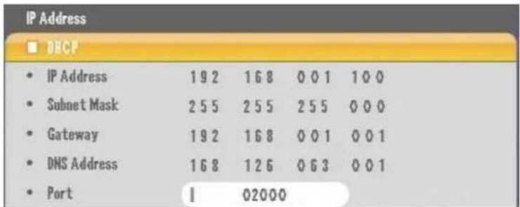
IP Address
Subnet Mask Address
Gateway Address
DNS Address
The Port number by default is 3000. This can be changed to the requirements of your network.
to the DVR. The IP address assigned must match the IP Address scheme of the network the DVR is connected to. For example:
Gateway Address.....192.168.0.1
Subnet Mask Address..... 255.255.255.0
IP Address must be..... 192.168.0.X (x = a number between 2 and 254 because 255 is reserved for the subnet address and 1 is set as the gateway address)
DDNS Address
DDNS (Dynamic Domain Name Service) is a feature that can automatically update a dynamic IP Address (ex. 10.10.10.01) using a domain name (ex. hp://DVR.DDNSIP.NET). This service enables an user with a Dynamic IP Address to have a stac domain name for hassle free remote access to their DVR(s).
The address you see here by default is the IP Address to a general DDNS server. Please DO NOT change this address while con guring your DVRs' network se ngs. The changes you make under the DVRs' "DDNS OPTION" menu will not be acted by this address.
DDNS Address
61.250.157.14
Transmission Opon
The Transmission Op on menu is used to either enable or disable the DVRs' Dual Stream funcon.

Figure 85 Dual Stream Opon
What is the Dual Stream Funcon?
This DVR is capable of having independent Recording sengs (Resoluon/Frame Rate/Video Quality) from what is transmied over the network. The Dual Stream funcon enables users with slower internet conncon speeds to maintain a high recording seng (Resoluon/Frame Rate/Video Quality) while lowering the resoluon (preset at CIF – 360x240 pixels) for faster frame rate transmissions over your network. Enable this feature by setting it to "Use", disable this feature by setting this option to "Not Use".
Web Server Port
Web ServerPort
1 00080
This DVR has two methods for remote access, the client soware (CMS, PRMS, Mobile, Mac PRMS) and web browser (Internet Explorer Version 6 and up ONLY). Remote Client Software access uses the "Port" number mentioned above under the "DHCP" section. Web browser (Internet Explorer) access uses the web server port number. The default value is port number 80 (the standard web server access port number). This port may be changed to comply with your current network conguraon. If the web server port number is changed, you must make sure to specify the port number when entering the DVRs' IP address or DDNS for remote access. For example:
Chapter 11. Network Section In-Depth
- IP ADDRESS GUI
If the web server port was changed to 85, then you must enter – hp://10.10.10.1:85/ (when using the IP address), or hp://DVR.DDNSIP.NET:85/ (when using DDNS)
3. E-MAIL SETUP GUI

This DVR supports email nocaon for events. This secon is used to setup the email server and account sengs to send these nocaons by email:
SMTP Server
smtp.naver.com
SMTP (Simple Mail Transfer Protocol) Server – This is the outgoing email server address.
Use Port
00025
Use Port – This is the port number used by the outgoing email servers.
Account
• ID
jsyang
- Password
268573000
Account – The email account (ID) and password (password) used for the outgoing email server. Select this check box on if your outgoing email server requires authencaon.

From
jsyang@naver.com
From – Enter the senders email address for email nocaons.
| To | soon@yahoo.com |
| 1 | |
| 1 |
To - Enter the recipients email address, where the nocaons are emailed to. You can set up to three email addresses.
4. DDNS OPTION GUI
DVR's DDNS service oers built in DDNS services or if chosen oers other DDNS services available by following DDNS sites:
www.dyndns.org
www.no-ip.com
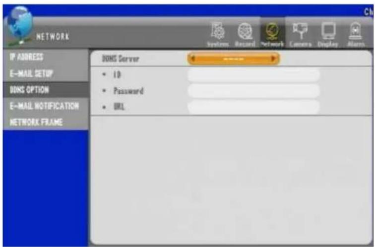
Figure 86 DDNS OPTION GUI
These are two built in services with this DVR. Please select either service and specify the following:
ID – The ID registered with either dyndns.org or no-ip.com
Password – The Password registered to the corresponding ID with either dyndns.org or no-ip.com
URL (Uniform Resource Locator) – The domain name registered with either dyndns.org or no-ip.com
Built in DDNS Server setup
There is a third DDNS server that we oer free of any charges. Follow the instrucons below:
-
Access The DVRs' "System" menu, then "Informa on"
-
Make a note of the "Webcode"
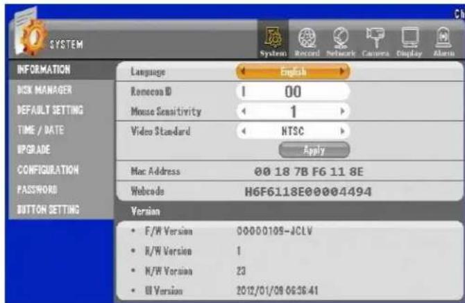
Enter the Webcode and DVRs' Domain Name. It can take up to 30 minutes for the registraon process.
Access your DVR via Internet Explorer by entering: "The DVR DOMAIN Name.DDNSIP.NET Make sure all port forwarding rules have been set on your rewall. YOU MUST SPECIFY THE WEB SERVER PORT IF CHANGED UNDER THE DVRS'
Figure 87 System Informaon GUI
- Go to hp://www.ddnsip.net. Enter the "Webcode" and domain name of your DVR. Then press the "Register" bu on. You will receive a "Registra on Success" message if your DVR was registered. Please note that the domain name must be unique to every domain name registered with our DDNS service.

DDNSIP.Net example
Free DDNS is used for remote conneccon through private DDNS service. (In case of dynamic IP user, it is recommended to use the private DDNS service instead of using manufacturer's DDNS server)
Firstly, go to hp://www.dyndns.com to create an account. Then, if your DVR is connected to a router, you must do the DMZ seng for your DVR IP in the router setup. DMZ is a funcon to open all the ports for the selected IP.
For example, here is the way how to create an account with the name of hongkildong.
[1] For creang an account, visit the website: hp://www.dyndns.com

Figure 88 DynDns.com Site
[2] Create the sub domain name (Example: DVR-Sample) and select the main domain name provided with free. A user may select any name and then click the "ADD" button.
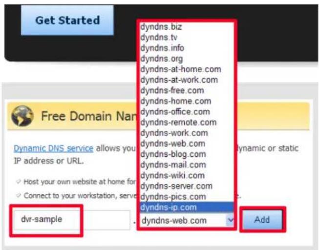
Figure 89 Free DNS using dynds-ip.com
[3] Then, input the detailed user informaon. Aer lling in user name, password and e-mail address, etc., then click "Create Account" bu on. For e-mail vericaon, receivable e-mail address is required.

Figure 90 Creang account in DynDns.com
[4] When you see that the e-mail has been sent to you for vericaon, then check the e-mail.
Figure 91 Conrmaon Email
[5] Aer opening the vericaon e-mail, if you click the link, the vericaon is proceeded automacally.
Your DynDNS.com Account 'hongkildong' has been created. You need to visit the confirmation address below within 48 hours to complete the account creation process:
https://www.dyndns.com/confirm/create/7rlxBd8xrjmarhmoJrJJA
Our basic service offerings are free, but they are supported by our paid services. See http://www.dyndns.com/services/ for a full listing of all of our available services.
If you did not sign up for this account, this will be the only communication you will receive. All non-confirmed accounts are automatically deleted after 48 hours, and no addresses are kept on file. We apologize for any inconvenience this correspondence may have caused, and we assure you that it was only sent at the request of someone visiting our site requesting an account.
Sincerely, The DynDNS.com Team Dynamic Network Services Inc.
[6] If the e-mail vericaon is completed, you can enter into the following website.

Figure 92 Acve Nocaon
[7] Aer log-in, click "My Zones/Domains" in "My Service" menu.

Figure 93 My Zone – DynDns.com
[8] Then, click "Dynamic DNS Hosts" in the menu on the le .
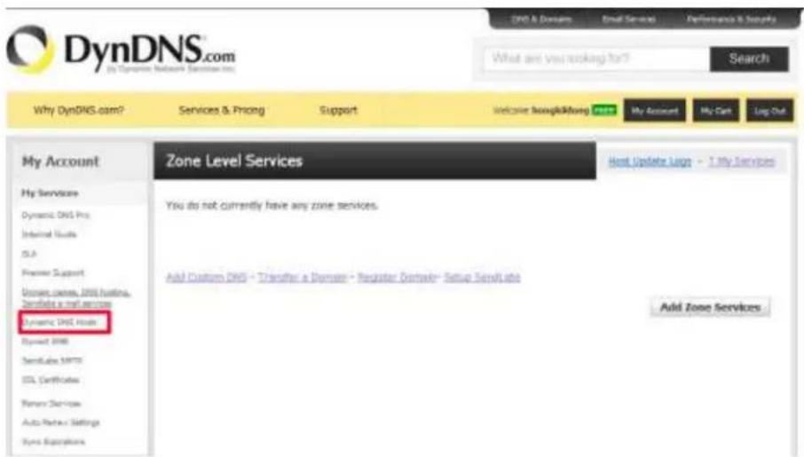
Figure 94 Host - DynDNS.com
[9] Click the rstly registered domain(dvr-sample.dyndns-ip.com)
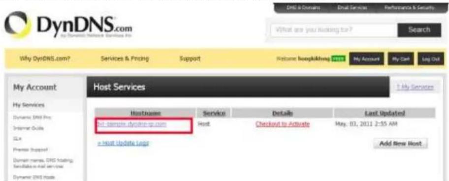
Figure 95 Check IP - DynDNS.com
[10] Input the public IP of installed router for IP Address. You can nd the public IP of the router when you check the router setup. When you complete the input, click "Save Changes".

Figure 96 IP Address - DynDNS.com
[11] To ac vate the registered domain, click "Checkout to Ac vate."
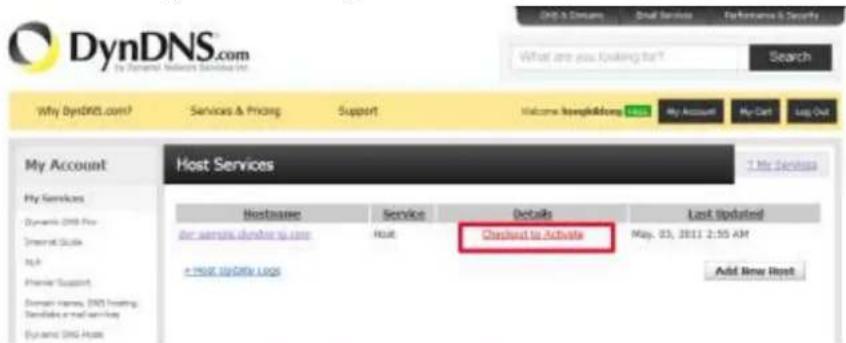
Figure 97 Acvate - DynDNS.com
[12] Then, click "Proceed to checkout" but on below.

[13] And click "Ac vate Services" below.
Once you have confirmed the contents of your cart your services will be instantly activated.
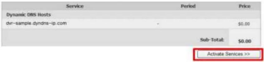
[14] Then, selected domain IP is acvated.

[15] Enter the ID/PW and domain set to the DVR. It's for the rou ne renewal when the IP is changed.

(Example)
[16] Enter the domain name registered in the URL address to connect.

Note: The service is available aer 10 to 30 minutes since the subscripon
5. EMAIL NOTIFICATION GUI

Figure 98 Email Nocaon Secon
This menu is used to select the type of events that will be sent by the email nocaaon feature:
Mail Title – The subject like of the email nocaaon
Interval – How oen the email nocaon will be sent, e.g. an email nocaon one minute, every 5 minutes, etc...
Sensor – When a sensor is triggered (Any sensor or trigger device connected to the Sensor in ports on the DVR)
Moon Detecon - When moon is sensed on a specific camera(s)
Video Loss – When a speci c camera(s) loses its' video signal
Power On – When the DVR reboots or is powered on
Password Modify – When a password is changed for a user account on the DVR
HDD Error - When there is an internal error on the hard drive of the DVR, e.g. temperature threshold exceeded or failure to recognize the hard drive.
6. NETWORK FRAME GUI
| CH | 120/120 fps | Quality | CH | fps | Quality |
| ☒ | 1 fps | Lowest | |||
| ☐ 1 | 7.5 fps | Normal | ☐ 9 | 7.5 fps | Normal |
| ☐ 2 | 7.5 fps | Normal | ☐ 10 | 7.5 fps | Normal |
| ☐ 3 | 7.5 fps | Normal | ☐ 11 | 7.5 fps | Normal |
| ☐ 4 | 7.5 fps | Normal | ☐ 12 | 7.5 fps | Normal |
| ☐ 5 | 7.5 fps | Normal | ☐ 13 | 7.5 fps | Normal |
| ☐ 6 | 7.5 fps | Normal | ☐ 14 | 7.5 fps | Normal |
| ☐ 7 | 7.5 fps | Normal | ☐ 15 | 7.5 fps | Normal |
| ☐ 8 | 7.5 fps | Normal | ☐ 16 | 7.5 fps | Normal |
Figure 99 Network Frame GUI
The Network Frame menu needs to be configured if you enable the "Dual Stream" feature. This menu is used to congregate at what frame rate and video quality the DVR will stream over the network while using Dual Stream. Please refer to Figure 85 Dual Stream Option on page 108.
The frame rate and video quality can be congured per channel. A specied channel can be disabled or enabled by selecng the camera icon located to the right of the channel number.
Camera Enabled
Camera Disabled
You have a maximum of 120 frames to distribute amongst the available channels.
Chapter 12. Camera Secon In-Depth
In This secon we will be covering Camera secon, where there are controls for adjusting property, naming, PTZ, and viewing aspects of the Camera.
1. CAMERA SETTING GUI
Camera Sengs GUI has open to control Covert, AGC, Stac Gain, Brightness, Contrast and Hue.

Figure 100 Camera Seng GUI
Covert: Controls the camera to be displayed on the Live view or not. As long as camera is chosen on the "CH" sec on it will conduct the recording even if you choose to have it chosen to covert.
AGC: AGC is short for Automac Gain Control. It will determine the best possible gain onpon for the camera to show proper signal gain. Gain control is needed for those cameras that are installed far away. They oen mes loose signal strength and with Gain control you may improve the signal strength. AGC will try to detect the level of the signal and try to compensate internally.
Stac Gain: Stac Gain opon only gets enabled if you do not choose to use the AGC feature. Unlike the automac gain the stac gain control enables the opon to increase and decrease the gain by user interven on. Use this op on if you need to ne tune the camera's gain to desire output.
Brightness: Brightness controls enable the camera to be dim or bright in selectable level increments in 5% every step by 0%\~100%.
Contrast: Contrast controls enable the camera to be sharper line edges in 0\~100% level.
Hue: Controls the hue of the camera visual in range of 0\~100% level.
2. PTZ SETTING GUI
In PTZ seng GUI there are 2 dierent menu screens as described below.
![CAMERA System Record Network Camera Display Alarm CAMERA SETTING PTZ SETTING CONTROLLER CAMERA TITLE PTZ TOURING SERIAL PORT SETTING CH Model CH Model ELMO-400C [None] [None] [None] [None] [None] [None] [None] [None] [None] [None] [None] [None] [None] [None] [None] [None] [None] [None] [None] [None] [None] [None] [None] [None] [None] [None] [None] [None] [None] [None] [None] [None] [None] [None] [None] [None] [None] [None] [None] [None] [No] [None] [10] [11] [12] [13] [14] [15] [16]](/content/2026/05/1024313/images/0a94d5c7ec537a612fa3e458b3682c33f9a41d5c00df7affb82b3f7d564a6f57.jpg)
Figure 101 PTZ Seng GUI 1
If you press the then the additional PTZ seng can be dened.

Figure 102 PTZ Sengs GUI 2 - Additional Sengs
[Note] In case of using more than one PTZ camera, ID should be dierent. Refer to PTZ camera manual for changing the ID.
Additional PTZ seng
Select the icons described below.


-
Serial Port: Select "RS-485" or RS-232 for the PTZ camera control.
-
Reverse Control : Moves reversely when PTZ moves.
- Touring Mode
- DVR : A PTZ camera works by the touring conguraon set in DVR.
- Camera : A PTZ camera works by the touring conguraon set in PTZ camera.
- Speed: Set the response speed for each feature. (Default: 3)
- Change ID : Select "ID View" to be informed of or change PTZ camera's ID. Enter "Changed ID" and then select "Apply." (If the change is not permissible, you should directly change through the PTZ camera.)
3. CONTROLLER GUI
You can connect a keyboard to operate the DVR. And the joysck control is very convenient to PTZ control.
![CAMERA CAMERA SETTING PTZ SETTING CONTROLLER CAMERA TITLE PTZ TOURING SERIAL PORT SETTING Model: [Note] Controller ID: 0 Serial Port: RS-485](/content/2026/05/1024313/images/acb756723f9d10a749203610ea34eb95fc6a75a37f6d051342992c8674ef807c.jpg)
Figure 103 Controller GUI
Model: Select the model to connect to the DVR. You should check the compatibility between the keyboard and DVR before purchasing.
Controller ID: The default value is "0" for the ID. If you want to use different ID, you should change the keyboard ID too.
Serial port: Use "RS-485" or "RS-232"
Note: Refer to the instrucon manual for the detailed keyboard operaon.
4. CAMERA TITLE GUI
You may change the tle of the camera to give more geographical name or any desire name.
Some camera locaon may be idened easier by giving logical name to the camera. Here are steps to give logical name label instead of having default label.
Step 1. Select "Camera" item on upper main category and select CAMERA TITLE

Figure 104 Camera Title Menu
Here you may choose camera(s) that you want to give logical name and repeat to other camera(s) as needed. In this example we have chosen Camera 1 marked Ch1 and will change the label to door1.
Step 2. Click Camera Number to change then use the on screen key pad to change the label as shown below. When done giving name select and choose OK to end typing.
![Ch1 door1 0 1 2 3 4 5 6 7 8 9 0 - = Y + q w e r t y u i o p [ ] + Shift a s d f g h j k ! : + + Space z x c v b u m . /](/content/2026/05/1024313/images/9fd2098d2fba71421415f202fbb355c8a9807adae1ef59a86a65cccfd2cbb6de.jpg)
Step 3. Exit the menu and select YES to apply the seng

Names of the camera must be changed each individually and they are shown on both the live and recorded playback.
On CMS and other mobile clients will also show the changed camera labels.
5. PTZ TOURING GUI
This seng allows the PTZ camera to move repeatedly by previously selected order.

- Select channel : Select a channel to install PTZ camera.
- Preset : Select preset number
- Speed : Select speed
- Dwell Time : Select the stop period of PTZ Camera [Note] Up to 12 presets is available.
6. SERIAL PORT SETTING GUI
Serial Port Seng GUI is divided in RS-485 and RS-232 secon as shown below.
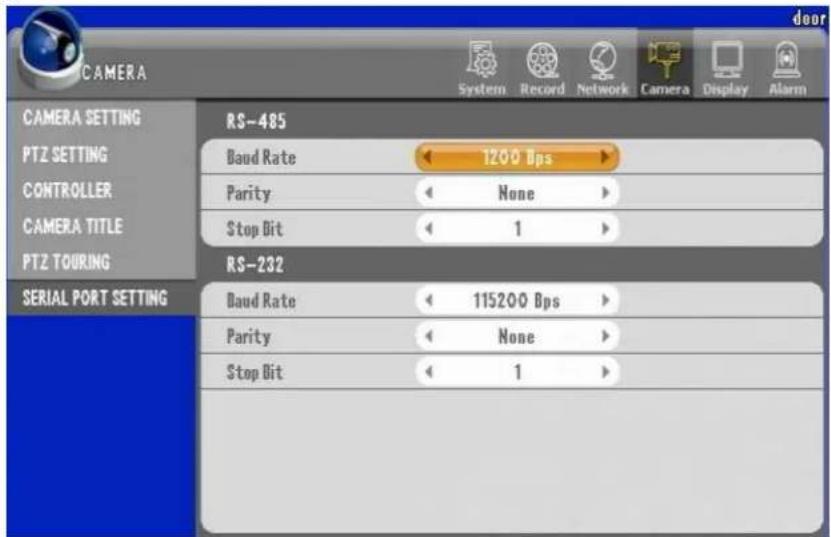
Figure 105 Serial Port Seng GUI
Set Baud Rate, Parity and Stop Bit for RS-485 and RS-232 communicaon.
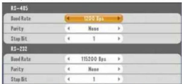
Figure 106 Baud Rate, Parity and Stop Bit
The Seng is variable depending on the PTZ camera model. Refer to the manufacturer's manual.
7. How to operate PTZ camera
Select a channel and press the "PTZ" bu on to call PTZ control OSD.

[By using the front direcon buon (Or remote controller)]

- Use the direc on bu on to move the PTZ camera.
- Whenever pressing the Enter buon, the feature changes in the order of Pan/Tilt, Zoom and Focus. Use buons on the right and le side to move.
[By using the mouse]

natural_image
Diagram showing directional arrows and two oval shapes on a blue background, no text or symbols present- To call the PTZ control menu, scroll the mouse wheel. Then, the feature changes in the order of Pan/Tilt, Zoom and Focus.
Chapter 12. Camera Section In-Depth
7. How to operate PTZ camera
- Pan/Tilt : Click the mouse on the screen to move.
- Focus : Click the right or le on the screen to adjust focus.
- Zoom : Click the right or le on the screen to control zoom.
[PTZ menu]
On the front panel, if you select PTZ buon from the PTZ mode, the funcon menu is displayed as below.

| Able to change direcon of pan-lt camera | ||
| Able to change into “extend and minimize pan- lt” | ||
| Able to change into camera focus mode | ||
| Touring feature | ||
| Able to retrieve menu built in pan-lt camera | ||
| Able to operate automatc focus funcon | ||
| Able to enter pre-set No. and save | ||
| Enter and press preset No. to move and then camera moves accordingly | ||
| Able to enter preset No. | ||
| Change channel | ||
| exit |
Chapter 13. Display Secon In-Depth
Display secon controls how local view (view from monitor directly connected to DVR) is congured.
1. OSD GUI
On OSD (On Screen Display) GUI you have control over showing or not showing "Camera Title", "Status Bar", and "Split Border"

Figure 107 OSD GUI
Camera Title: Camera Titles are shown on the upper right corner of each camera secon.

Figure 108 Camera Title Locaon
Status bar: Display the status bar on the boom of the screen. There are informaon such as Time, Record status, Lock, Network and HDD capacity remained in the status bar.
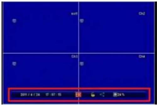
Figure 109 Status Bar Locaon
Split screen: Display the split screen (as default white line is drawn if you unselect it then there will be no boarder between pictures)

natural_image
Pure geometric diagram with blue background and red cross lines, no text or symbols presentFigure 110 Split Screen Lines
2.SPLIT / SEQUENCE GUI
There are opons to control how split view and its sequence appearance could be congured.
It is controlled by SPLIT /SEQUENCE GUI shown below.
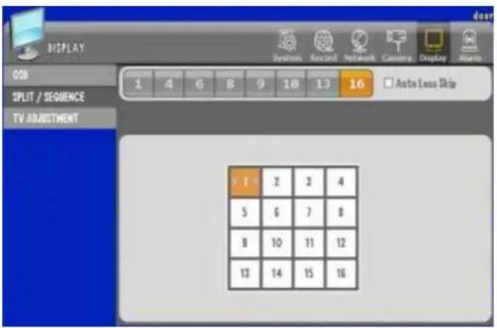
Figure 111 Split / Sequence GUI
In above example shows 16 channel split that has no "Auto Loss Skip" enabled.

Figure 112 Chanel Selector
There is also display order selector as seen below for 16 channel example.
| 1 | 2 | 3 | 4 |
| 5 | 6 | 7 | 8 |
| 9 | 10 | 11 | 12 |
| 13 | 14 | 15 | 16 |
Figure 113 16ch split display order
In the box with camera number 1, if selected the right or le arrow will appear where you can choose which camera will be sown on 16 channel split window. You may do this for all 16 combinaon to choose the order of the camera.

Figure 114 1ch split conguraon

Figure 115 4ch split conguraon

Figure 116 6ch split conguraon

Figure 117 8ch split conguraon

Figure 118 9ch split conguraon

Figure 119 10ch split conguraon

Figure 120 13ch split conguraon
Dwell Time: All split conguraon except 16 channel split conguraon you could set dwell me represented in seconds.
Figure 121 Dwell Time selecon
Order Selecon: All Channel box are selectable and may change the order of it except 1 channel split conguraon.
Figure 122 Order selecon
Auto Loss Skip: If congured (checked) then any missing or video loss camera will not be shown on selecon menu and it will auto populate according to empty slot. EX: if camera number 15, 16 is lost, then on 9 channel split 1^st batch will show 1 9 cameras next will show 10 14 and 1 4 on 2^nd batch.
3. TV ADJUSTMENT
In this secon you will use the conguraon to adjust resoluon and Icon size.

Figure 123 TV Adjustment
VGA: VGA (Resoluon) selectable 800X600, 1024X768 or 1280X1024
Icon: Icon there are Normal, VGA and Small.
Chapter 14. Event Secon In-Depth
1. SENSOR GUI
This DVR supports 4 sensor inputs for all 4 channel, 9 channel and 16 channel DVR.
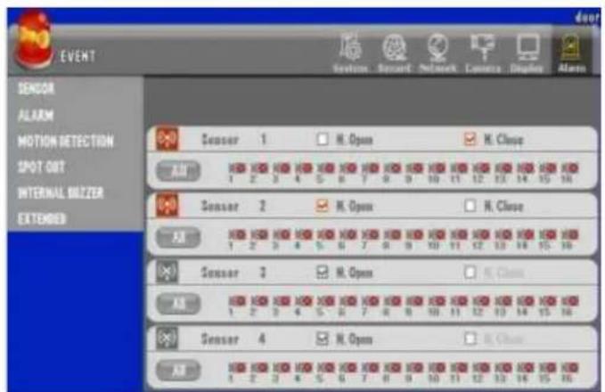
Figure 124 Sensor GUI
Enable Sensor: Select the sensor to use.

(Use)

(Not use)
Input Type: Choose between Normal Open and Normal Close.
- N/Open (NORMAL OPEN) : The contact is normally opened but it will be closed when the signal is triggered
- N/Close (NORMAL CLOSE) : The contact is normally closed but it will be opened when the signal is triggered
Related Camera: Select the camera to be connected with the sensor. Mul-conncon is available.

(Not use)

(Use)
2. ALARM GUI
You could con gure how each "Events" (Mo on, Sensor, Video Loss) respond with me individually as shown below.
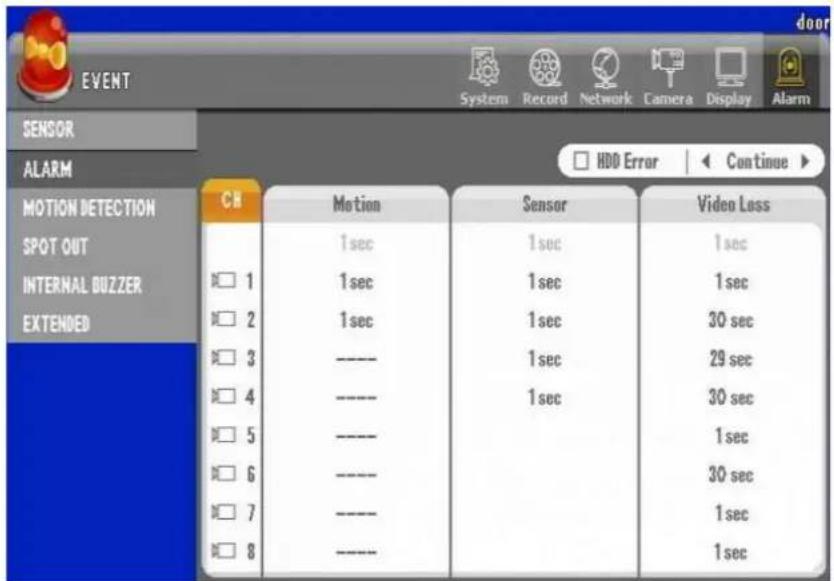
Figure 125 Alarm GUI
Select the alarm duraon me on each event (Moon, Sensor, Video Loss)
In case of selecng the alarm duraon me in blue-colored, it is applied to all channels
| CH | Motion | Sensor | Video Loss |
| 4 sec | 3 sec | 5 sec | |
| 1 | 7 sec | 4 sec | 5 sec |
Select the HDD Error and alarm duraon me

3. MOTION DETECTION GUI
You can set the sensitivity and detectable area in order to record when the moon event is triggered.

Figure 126 Moon Detecon GUI
Select the channel: Select the channel using for the moon detecon.

(Not use)

(Use)
Sensitivity: Set the sensitivity to be detected.

- The larger the number is, the higher the sensitivity is (1\~10).
- If the sensi vity is selected with Schedule, you can set the sensi vity by each hour. You use this op on to control sensivity control for night and day. Some light angels may create larger moon due to the locaon of the shadow or other eects.

Figure 127 Indicaon of Hourly conguraon of Sensitivity
Range: Set the area where a moon would be detected.
There are also indications in pink color when moon is detected. It also serves as feedback on your sensitivity sengs. If you see the pink color in the grid you choose for moon then such moon acvity is sensitive enough to be detected. Please use trial and error to congure it just right.

natural_image
Interior view of a computer lab with server racks and equipment (no visible text or symbols)Set the area by using the direc on key(or mouse dragging) and press "Enter".
- Select the area where the moon is detected: The selected area is outlined with blue.
- Cancel the area where the mo on is detected: No signal
- The area where the moon would be detected is marked with red.
Note : You can use the hot key to set all areas.
- No. "1": Select all
- No. "2": Cancel all
4. SPOT OUT GUI
This seng enables the monitoring by the second monitor and also provides the display mode such as Event popup, Sequence, Event + Sequence and Fixed channel.

Figure 128 SPOT Out GUI
Set Sequence Dwell Time: Available to set from 0 to 30 seconds
Spot Mode:
• Event : When an event is triggered, the relevant channel video is popped up.
- Sequence: The selected channels are displayed sequentially for the selected dwell me.
- Event+Sequence: While being displayed sequentially at no event, when an event is triggered, the channels triggered are displayed preferenally.
• Fixed Channel : Display the selected channel only

5. INTERNAL BUZZER GUI
When an event is triggered, the DVR buzzes for the selected me.
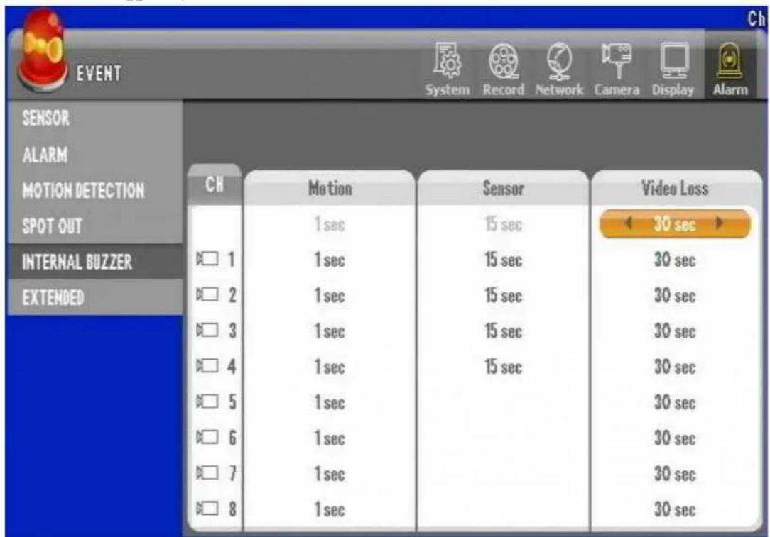
Figure 129 Internal Buzzer GUI
Range: 1 to 30 seconds ("----": Not use)
6. EXTENDED GUI
Once the extended box is connected, up to 16 sensor inputs and alarm outputs can be usable.
▶ Connecon diagram

Connect "Serial" port of DVR with "RS-232" port of the extension box.
Connect the power cable of extension box and then turn the power on.
▶ Descripon

① Power switch
② Power adaptor connector
③ RS-232 port (Port connected to the system)
④ Sensor input (1\~16)
⑤ Normal Open alarm output : 1\~16
⑥ Normal Close alarm output : 1\~16
Alarm Sensor extension box seng
Aer connecng the extension box, you should set to have the system working.
[1] Select the "Use" then move arrow to select check mark.


Figure 130 Extended GUI
You will have check mark appear as Figure 130 Extended GUI shows above.
Chapter 15. Search Operaon
In most cases search operaon may be done through the client applicaon, but some cases especially if you are going to perform evidence backup you will perform a search directly from the DVR unit itself. This chapter reviews how you could perform dierent types of search. There are 3 types of search Calendar, Event, and Date/Time search.
1. Geng to Search Screen
Search opon may be available by selecng the "Search" buon on the face of the DVR.

Figure 131. DVR Front Face with Search Buon
Or you may use the "Search" buon on the remote controller.

Figure 132 Search using remote controller
Or you may use the right mouse click then click on search buon on the screen with le mouse click.
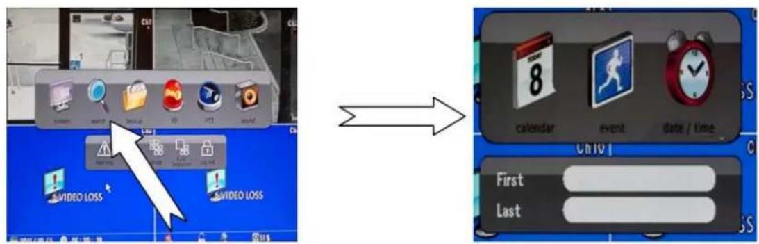
Figure 133 Mouse operaon to get to search menu
2. Calendar Search
Bring up menu that Figure 134 Search Menu shown below from search screen then press calendar.

Figure 134 Search Menu
Then you must click icon marked "calendar" to see below Figure 135 Calendar Search GUI.
Calendar search can be performed if there are available recording on HDD. They will be highlighted blue and upon selecon they indicate that corresponding items are playable.
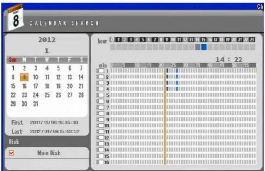
Figure 135 Calendar Search GUI
Chapter 15. Search Operation
2. Calendar Search
| Sun | M | T | W | T | F | S |
| 1 | ||||||
| 2 | 3 | 4 | 5 | 6 | 7 | 8 |
| 9 | 10 | 11 | 12 | 13 | 14 | 15 |
| 16 | 17 | 18 | 19 | 20 | 21 | 22 |
| 23 | 24 | 25 | 26 | 27 | 28 | 29 |
| 30 | 31 |
If there is a no recording present then dates are not selectable as you see on Figure 136 Calendar with no recording.
You must scroll thorough month and year to nd calendar with recording available.
Figure 136 Calendar with no recording

If there is a recording you will see date selectable in orange squares. In Figure 137 Calendar with recording 10^th day to 30^th day of this particular calendar has recording and currently 15^th day is selected to be viewed.
Figure 137 Calendar with recording
If there are no recording you will see the hour and minute indicator as seen below.
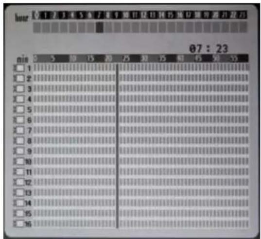
Figure 138 Hour and Min recording indicator
Chapter 15. Search Operation
2. Calendar Search
If you have any data on parcular hour and you will see mini blocks of 1 minute interval highlighted as seen Figure 139 Hour and Minute indicator with recorded data.
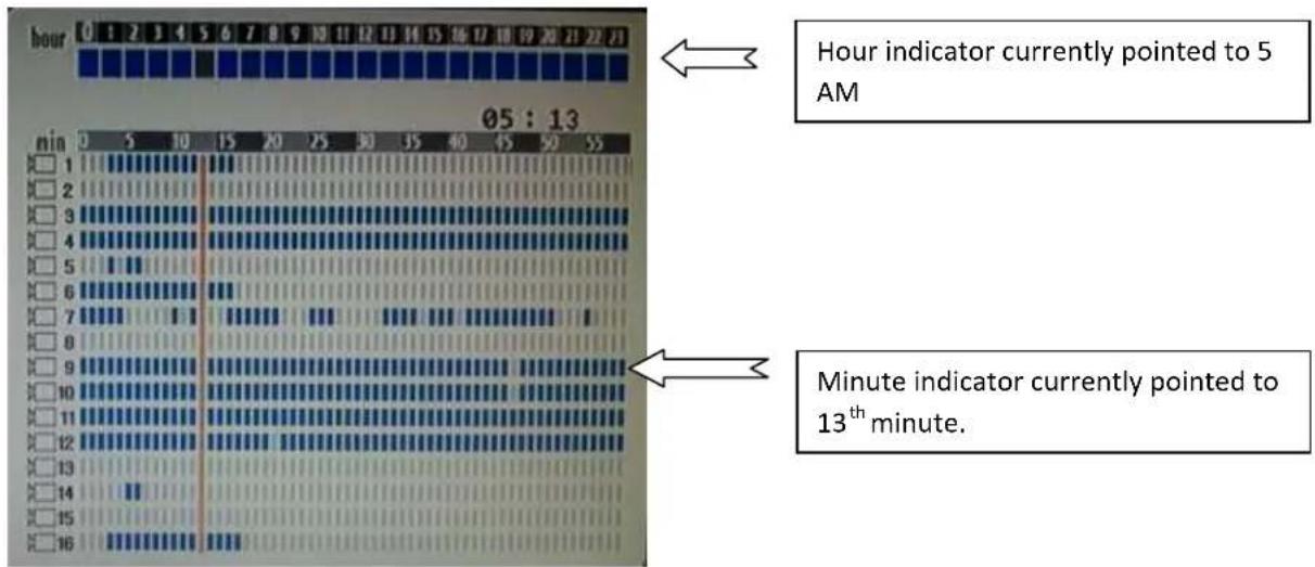
Figure 139 Hour and Minute indicator with recorded data.
The me bar is currently pointed to 13 ^th minute and hour is on 5 AM mark so from this point if “enter” buon on keypad, remote controller or double click on that indicaon line, you will be playing back video for selected date and 5:13 AM.
3. Event Search
If you have event recording enabled that you may choose such event from event list and perform a playback. You must see a menu that look like Figure 134 Search Menu seen below.
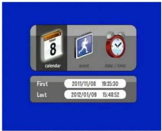
Figure 140 Search Menu
Then you must click icon marked "event" to see below Figure 135 Calendar Search GUI.
Then you will see below GUI screen page.

Figure 141 Event Search GUI
On this Figure 141 Event Search GUI Moon is highlighted if you press search buon then only then you will have list pane populated with events.

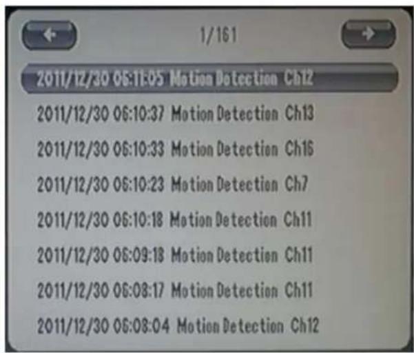
Figure 142 Populated List Pane
As you can see only if you conduct search will it show the list item and as shown on gure above there are 161 pages available for example above. You may have dierent result.
You need to also highlight the type of event that need to appear on list pane by selecng the event.
Selected events will show from gray coloraon to Blue for Moon, Red for Sensor, Pink for Video Loss as shown below.

Figure 143 Event type and Search
Clicking on the item on event list pane will start the playback of the event.
4. Date and Time Search
If you know exact me of search that you want to perform you may use the date and me search.
Date and me gure can be changed on screen below by selecng month, day, year, hour, minute then second.
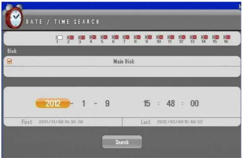
Figure 144 Date and me search
Then press on search to directly playback on me you desire.
5. Playback Control Menu Bar
Below you see the actual playback via the 16 channel DVR. Even though there are 16 cameras recording on moon only certain camera appear. Cameras that show video images are those that have recording for that parcular me. On a event recording (Moon, Sensor) there will some me slot where there be no recording due to the fact that it did not trigger the event.
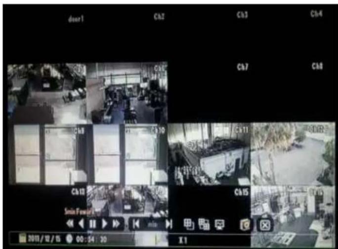
Figure 145 Playback screen with event recording
Example in Figure 145 Playback screen with event recording, ch5, ch6, ch9, ch10, ch11, ch12, ch14 and ch16 has playable video recording for that particular me selected to be played back.
Playback Controls
Playback Controls are available with right buon click with mouse, however with remote controller and frontal keypad you may have to click certain buon to obtain the same result as operang Playback Controls.

Figure 146 Playback Controls
If you observe the play control on the boom of the screen as shown on Figure 146 Playback Controls you will see playback control divided in three groups.
1^ST group is speed control which mouse, keypad, and remote controller are able perform all possible acons.
Chapter 15. Search Operation
5. Playback Control Menu Bar

Figure 147 Speed Control
Play and Pause operaon
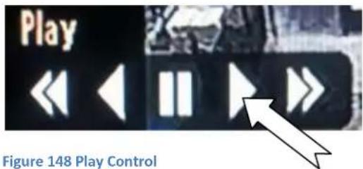
Play and pause by mouse operaon is simply clicking desired locaon to obtain the result. However for frontal keypad and remote controller you must pres enter key to obtain the result for play and pause.
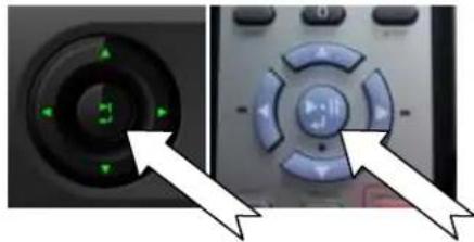
natural_image
Close-up of a remote control interface showing a circular dial with green indicator lights and directional arrows (no text or symbols visible)Fast Play, Rewind Operaon
You may use fast forward opon with mouse by pressing doubled arrow mark. Or press right direconal key.

Figure 149 Fast Play
Chapter 15. Search Operation
5. Playback Control Menu Bar
Also you may do the same with reverse play and fast play backwards by operang it with mouse on Speed Control, or key pad.


natural_image
Close-up of a remote control interface showing a green circular button and a blue play button with arrows (no text or symbols visible)Figure 150 Rewind and Fast Rewind.
They are selectable by 1X, 2X, 4X, 8X, MAX forward and backwards play view.
Mouse Only Operaon
Some operaons like the 2nd group of Playback Controls are fully functional only for the mouse operaon. Some operaons are available with key controls but not all will operate the same way because with key controls the full Playback Controls are not available.

Figure 151 View and Audio control for playback
Forward and backward 5 minute interval is only available via the mouse operaon.
With View Control and View Interval opon some acons are available via the keypad operaon but not as detailed as mouse operaon using Play Back Controls.
The View Control opon in keypad and remote controller, you are may press the Quad buons, as shown on gure below.

Figure 152 Quad Key Layout
However only the max view in case of 16 channel DVR between 1 and 16 channel view, in case of 9 channel DVR between 1 and 9 channel or in case of 4 channel DVR 1 and 4 channel view will be available. With using mouse on view control you may have many opon of view as shown below.

Single View
Quad View

6 View

8 View
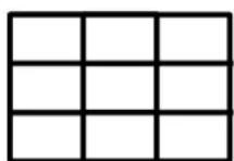
9 View
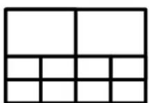
10 View
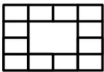
13 View

16 View
Figure 153 Mouse only view control
View Interval Opon
View Interval opon will scroll the next set of camera in view control view as an example of quad view on Figure 153 Mouse only view control if you press view inter opon buon then next set of the 4 cameras will appear.
De-Interlacing Opon
De-Interlacing Opon is available for high speed moon view that will have image tear. Our recorded video images are complied by using right and le eld. So for those images that has fast moving object you might observe image tear due to video sync dierence between right and le eld. De-Interlacing Opon shows the picture in a eld view rather than frame view. So by using the De-Interlacing opon you will eliminate the image tear on playback images.
Audio in Playback Opon
Audio is only other opon that will fully funcon by pressing audio key or by mouse control. It enables the audio and adjusts the audio volume for the playback video.
Chapter 15. Search Operation
5. Playback Control Menu Bar

Audio opons by default shows audio level 50% volume with second click you will be able to mute the audio. By moving the level adjust bar you are able to control the volume level.
Quick Backup During Playback
While playing the video back you do not have to exit the playback view to conduct a quick backup to media of your choice.
You need to click on backup key or click on buon shown below to mark an index locaon of where this backup point will start.

Figure 154 Quick Backup
Then you will see indicaon on the screen "Mark In" as shown below.
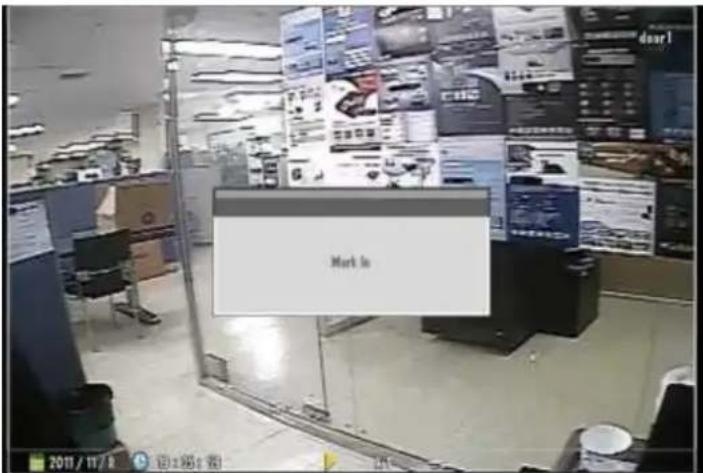
Figure 155 Mark In
Chapter 15. Search Operation
5. Playback Control Menu Bar
Aer if you press backup buon one more me you will now see the Quick Backup GUI to perform a backup operaon. What Mark In funcon does is that from when you 1 ^st press the backup buon or mouse equivalent operaon, DVR actually marks that exact me for Quick Backup GUI to start backup operaon.

Figure 156 Quick Backup on Playback
So in Figure 156 Quick Backup on Playback, Mark In was performed at 2011-Dec. 15^th 5:16 AM and you have an opon to back it up on USB because there is no CDRW present.
Chapter 16. Backup Operaon
Backup is the funcon to archive the recorded video to a storage device such as an extended HDD or USB drive. If an ODD is built-in, it's available to back up the les to the ODD as well.
Note
When you back up with the external HDD, please use the external HDD supplied the power from outside. The disk for backup should be formed with FAT32. And it's recommended to use the commercial software providing "FAT32 format" for the disk over 30GB capacity.
1. Calendar Backup
Connect the storage device for backup and then select "Backup" button.
Or you may press "backup" from main menu shown below.

Figure 157 Main Menu Items
Then you will see gure below

Figure 158 Calendar Backup
Select the camera
Chapter 16. Backup Operation
1. Calendar Backup
Select the camera to back up.


(Not select)

(Select)
Select the date
Select the date to back up.

Select the disk
Select the disk to back up.

- Main disk: Back up through the disk used as a main disk
- Mirror disk: Back up through the disk set as a mirror disk
Select the hour
Select the hour to back up

Select the minute
Select the minute to back up

Set the backup start me
Select the start me and then click the tap in the le side to set like the picture below.

Select the backup compleon me
Select the compleon me and then click the tap in the right side to set like the picture below. And then press Next.
Chapter 16. Backup Operation
1. Calendar Backup
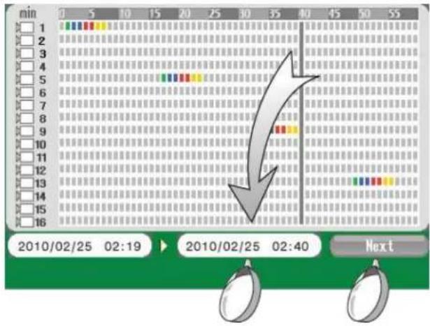
Note
Above me seng is applied only when the backup date and hour is same. If the backup date and hour is dierent, set the start me rst by seng date, hour and minute and then set the end me.
▶ Select the backup opon
You can select the following opons for backup.

- Device : Select USB when you back up through USB port. And Select CD/ DVD-RW when you back up with CD/DVD-RW.
- Backup Range : Display the selected backup me.
- Opon : Select
-Audio : Select when you back up by adding audio signal
-Backup Viewer : Select when you back up by adding a backup viewer program
Backup Size
You can check the selected size to back up and the size of storage device. If the selected data is over the size of storage device, you have to set the backup me again.
| • Device | 2406 | MB | Calculation |
| • Data | G2 | MB |
• Device: Display the memory size to back up
• Data : Display the data size you selected
Backup Password
When you start a backup, you can set the password.
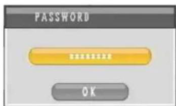
Backup process
Display the backup progress.
Chapter 16. Backup Operation
- Calendar Backup
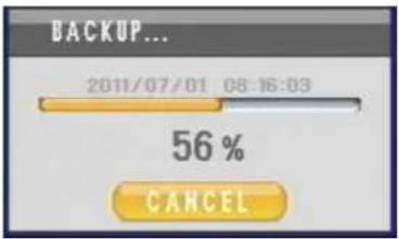
Display Backup Completed
Once the "Backup Completed" message is popped up, you may detach the storage device from the USB port.

2. Backup Viewer
You can play the backup les with the viewer program below.

viewer MS BackupViewer
Click to run the viewer program.

natural_image
Four-panel video frame showing underwater scenes with coral and ocean, no visible text or symbols(Backup viewer program)
| Icon | Descripon | |
| Open the le | ||
| Fast reverse playback | ||
| Reverse playback | ||
| Step backward | ||
| Pause | ||
Chapter 16. Backup Operation
2. Backup Viewer
 | Playback | |
 | Fast forward | |
| [CY2K] | Show the le list | |
| [ZAYH] | Switch to four split mode | |
 | Switch to nine split mode | |
| [38KV] | Switch to 16 split mode | |
 | Capture the image | |
| [20XX] | Control the Volume | |
| [ABW] | 2 3 4 5 6 7 8 9 10 11 12 13 14 15 16 | Select the channel |


AVI conversion
You can convert the backup le into AVI format le. Click the Start tap to set the start me. Click the End tap to set the end me. Click the AVI tap to start the conversion.

Chapter 17. Mobile and Remote Client Applicaons
1. iPhone
iPhone Applicaon Installaon
- Access the "App Store" from your iPhone or iTunes applicaon.
- Search for "MPRMS".
- Choose to download and install the applicaon (there is no charge to use our MPRMS applicaon).
- Aer the installaon is complete, launch the MPRMS applicaon from your iPhone.
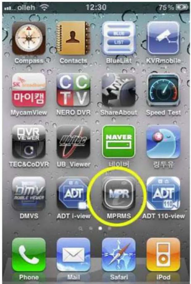
Adding a DVR To Your iPhones MPRMS Applicaon
Launch the MPRMS Applica on, and press "New"
Chapter 17. Mobile and Remote Client Applications
1. iPhone


Enter the "Reg Name" (Registra on Name). This can be any name to identify the specied DVR. Make sure there are NO SPACES in the Reg. Name.

Select the DVR Model:
H.264 DVRs' = DVR
Chapter 17. Mobile and Remote Client Applications
1. iPhone
MPEG4 DVRs' = FDS-110
MJPEG DVRs' = MJPEG
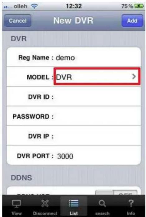
Enter the login informaon of the DVR. The login informaon MUST MATCH the login informaon on the DVR.
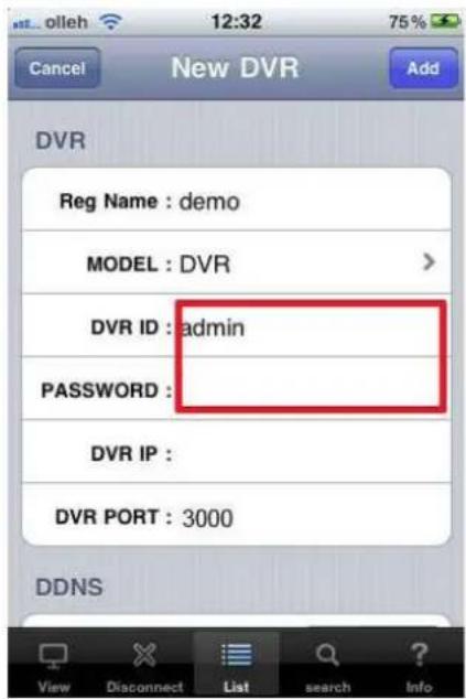
Chapter 17. Mobile and Remote Client Applications
1. iPhone
DVR ID: Enter the User ID for accessing the DVR.
Password: Enter the password for accessing the DVR.
Enter the DVR IP Address & Port Number (You can also enter the domain name address here)
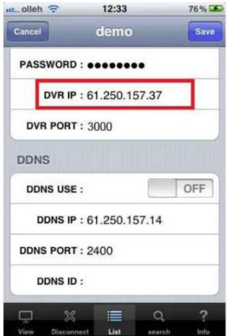
Please disregard this conguraon opon if you are using DVR within the United States. This feature is used in the following regions:
Asia
Connecng to the DVR
Press the DVR on the site list to connect
NOTE You will be prompted that there will be a "N/W Connec on Charge". THIS IS ONLY A REMINDER TO USERS WITHOUT AN UNLIMITED DATA PLAN, WE WILL NOT CHARGE YOUR ACCOUNT FOR DVR REMOTE ACCESS.
Chapter 17. Mobile and Remote Client Applications
1. iPhone


Connect remote access
Chapter 17. Mobile and Remote Client Applications
1. iPhone
![2011-06-14 12:36:25 LIVE demo Ch3 [360*240] 03F 1 2 3 4 5 6 CH SELECT 7 8 9 10 11 12 OUTPUT CTRL 13 14 15 16 Beep PTZ I Frame Only : OFF OSD OFF View Disconnect List search Info](/content/2026/05/1024313/images/a6703384ea467a2983777cbfc7dd7991fbfa313a8dc8c6bf64b179c61ae85d3a.jpg)

"CH SELECT" to select camera number.

PTZ: select when controlling pan-lt

The screen displays only video excluding me, resoluon and the name of
channel.

The feature is designed to transmit sll photo in certain intervals when video streaming is interrupted due to network load.
See full screen: If you set aside iPhone, it switches into full screen. (Touch any area of full screen viewer to retrieve menu)
Search from iPhone
Select "search" the icon below.

[1] Select Date/Time

Chapter 17. Mobile and Remote Client Applications
- iPhone

Switch to Live
Controlling Relay-Out from iPhone
Relay can be controlled remotely..
![OUTPUT CTRL olleh 12:38 77% [360°240] LIVE ONJ 03F Open Hired Hired Hired Hired Hired Hired Hired Hired Hired Hired Hired Hired Hired Hired Hired Hired Hired Hired Hired Hired Hired Hired Hired Hired Hired Hired Hired Hired Hired Hired Hired Hired Hired Hired](/content/2026/05/1024313/images/e675e3cf12d0d95495e54c5a757d0c551088af7ee1b14b05f80e04eaa1b3bf5d.jpg)
Time selecon : Set the duraon me of alarm output
O : Alarm o
Innity : Keep the alarm output connued
PTZ control from iPhone
PTZ control is available on iPhone. The way how to control is the same with on CMS and DVR
![20:11 08:34 [360*1] Jend Ch3 LIVE [360*240] OK ONCE FOCUS + - ZOOM + - Burs Focus PAN On Reset Save are View Disconnect List search Info](/content/2026/05/1024313/images/5189d01bc7f44a11c35888d1a50c3583d306a919332773fae63556a400930194.jpg)
Chapter 17. Mobile and Remote Client Applications
1. iPhone

(1) Select
(2) Cancel
(3) Automac camera focus
(4) Call the PTZ menu
(5) Direcon buon
(6) Camera focus control
(7) Camera zoom control
(8) Select the channel
(9) Relay out buon (A user can set relay out)
(10) Select the PTZ menu
(11) OSD display On/O buon for live screen
2. Android Phone
Program Installaon for Android
To install the program on the Phone, execute the 'MARKET' program and download the 'MPRMS' to install. If the installation is completed, you will see the 'MPRMS' icon on the main SCREEN.

(1)

(3)

Applicaon Execuon for Android
Select "MPRMS" to execute the program.
Chapter 17. Mobile and Remote Client Applications
2. Android Phone
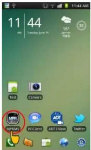
(Select the icon)

(Executed Program)
Register the product informaon for Android
Register the product informaon for remote monitoring.
[1] Register

Select "Add" to start the registra on.
[2] Enter the registraon informaon

(1)
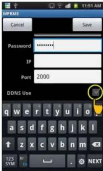
(3)

(1) Enter the name, Product ID(User) and Password.
Name : Enter any name you want.
User : Enter the "User ID" registered to the DVR.
Password : Enter the "Password" registered to the DVR.
(Note: "Menu" → "System" → "Password")
IP : This seng is only for stac IP users.
(2) A er selec ng "DDNS use", enter the "Password, IP and Port".
(Note: Dynamic IP user only)
(3) You can check the DDNS ID from the DVR menu: 'Menu' → "System" → System Informaon. Copy the 'WEBCODE' and enter it to DDNS ID and save it. (DDNS PORT is automatically changed as per the Webcode of DVR.)
Modify/Delete of Registered Informaon for Android
If you want to modify or delete the registered informaon, select the triangle-shaped icon.
Chapter 17. Mobile and Remote Client Applications
2. Android Phone
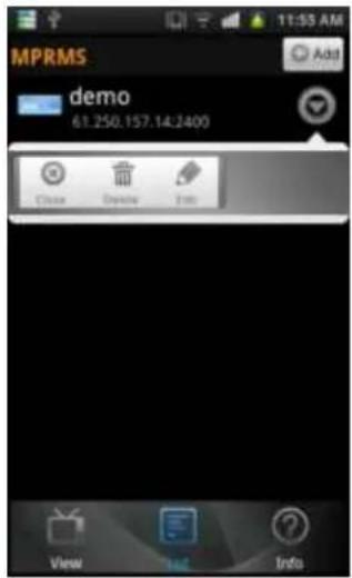



Select to edit the registered info.
Select to delete the registered info.
Close TOOL menu (As a dual funcon, it ends the conncon)
Remote conncon for Android
Select the registered list for conncon. Once you click the registered device, it shows the brief informaon like the 1 ^st picture below. If you click the red-colored background, detailed info. appears like the 2 ^nd picture. Click OK to execute the monitoring program.
Chapter 17. Mobile and Remote Client Applications
2. Android Phone
![MPRMS demo 61.250.157.14:2400 Information [demo] 61.250.157.14:2400 Do you want to connect? Active : WIFI OK Cancel](/content/2026/05/1024313/images/77b4da3270d7565f0ef81994e6c9e1091acb450c6599b15a79b4752e9dcce16d.jpg)
(Select the list)
![MPRMS demo Information [demo] 61.250.157.14:2400 Do you want to connect? Active: WIFI - mobile[UMTS] Info: web.sktelecom.com State: DISCONNECTED/DISCONNECTED Roaming: false -WIFI State: CONNECTED SSID: iptime_md2, BSSID: 00:08:9t:c1:8d:64, MAC: D4:E8:B2:74:8F:D6, Supplicant state: COMPLETED. RSSI: -83, Link speed: 11, Net ID: 2 IP: 192.168.9.10 OK Cancel](/content/2026/05/1024313/images/5cef9ed31da1ecc6296509ffff064286b4f610fa88cf058041ffd146f75d3b8d.jpg)
(Detailed info.)
Live view on Android
It shows the currently monitored images with real-me.

(1) Numeric Buon : Press a numeric buon to select a channel.
(2) 1 frame: When selected, it transmits a sll image with the certain interval in case the video streaming is interrupted due to the network load
(3) Show OSD: Select to display the info. such as channel name, date, me and event, etc.
Main menu view on Android
On the boom line of screen, there is a main menu. Select the menu to change the funcon


Go back to the previous step or close the monitoring program

Move to live mode (Channel change, 1 Frame and OSD display is available)

Go to PTZ mode

Go to PTZ preset mode

Go to search mode

Go to alarm mode

See the registered info.
PTZ control for Android
You can control the PTZ camera remotely.
Chapter 17. Mobile and Remote Client Applications
2. Android Phone
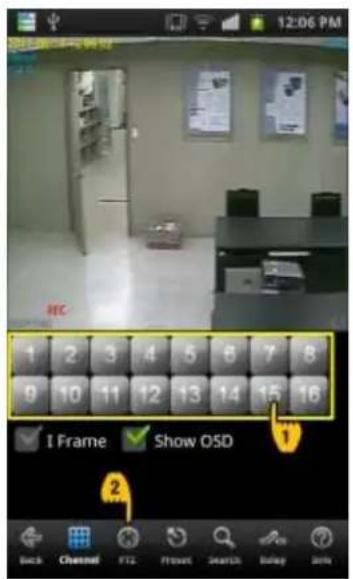
(Select PTZ mode)
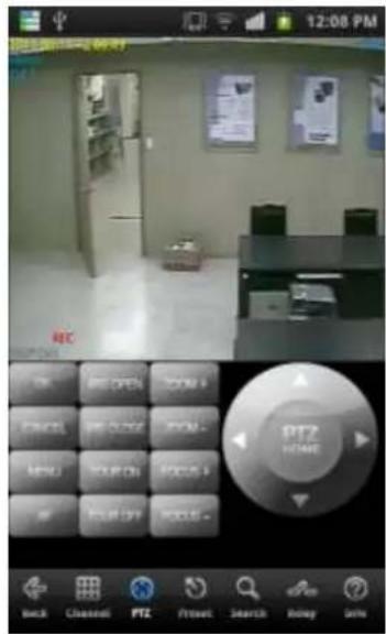
(PTZ mode screen)
(1) Go to PTZ mode
Select the PTZ connected channel and click the PTZ buon.
(2) How to control PTZ
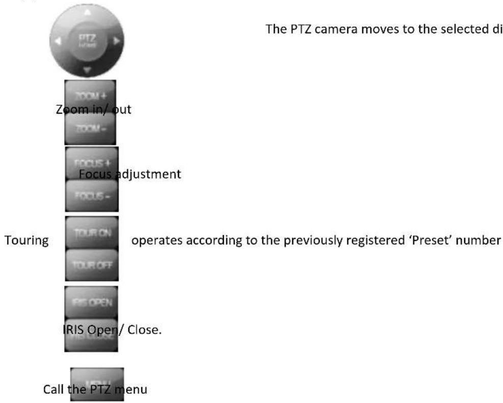
flowchart
graph TD
    A["PTZ Camera"] --> B["Zoom in/ out"]
    B --> C["Focus adjustment"]
    C --> D["Touring"]
    D --> E["Operates according to the previously registered 'Preset' number"]
    E --> F["IRIS Open/ Close."]
    F --> G["Call the PTZ menu"]
Chapter 17. Mobile and Remote Client Applications
2. Android Phone

OK buon for PTZ OSD menu

Cancel or the upper menu on PTZ OSD menu

PTZ Preset for Android
You can set the movement of PTZ camera previously and make the automac PTZ movement.

(Select preset mode)
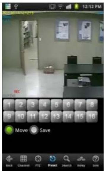
(Preset mode screen)
(1) How to go to PTZ mode
Select the PTZ connected channel and click the Preset buon.
(2) How to operate Preset
- Move: If you select "Move" and press a number, then the camera moves.
- Save: If you select "Save" and press a number, then the current loca on is saved.
Search on Android

(1. Select the search mode) (2. Select "Time Search") (3. Select the date and me)
(1) Select the search mode
(2) Select "Time Search": Select "Time Search" to enter the search conditions.
(Note: Select "To Live" to return to the live mode during the search.)
(3) Enter the date and me: Select the date and me and click "Start Search" for search.
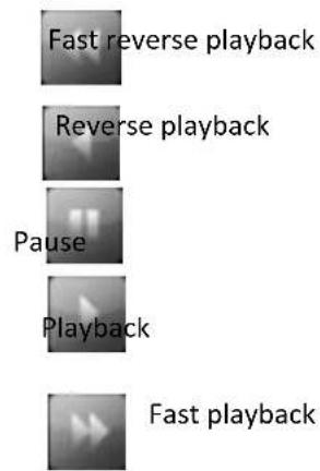
Chapter 17. Mobile and Remote Client Applications
- Android Phone
Relay Out for Android
Relay can be controlled remotely.
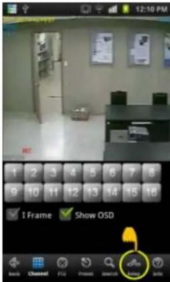
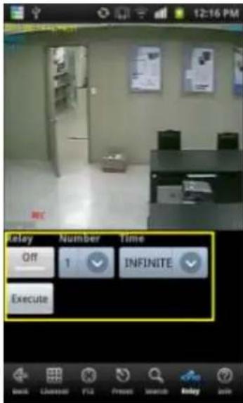
(1) Relay : Select On or O
(2) Number : Select the relay number.
(3) Time : Select the duraon me.
(4) Execute : Make the alarm output work
Chapter 17. Mobile and Remote Client Applications
2. Android Phone
Informaon display opon on Android
It shows the informaon of current conncon.

(Select info)

(Display the conncon info )
[Display Info]
Below is the example for an explanaon.
- IP : 61.250.157.37 : 2000 Via DDNS ← Connected IP informaon.
• MODEL : 16CH(63,xxx xxx:0) ← 16Ch model
- Webcode : H6F6057200001394 ← Product ID(Webcode).
• F/W : 84, N/W:21 ← F/W and network version.
• VSTD : NTSC ← VIDEO standard.
Chapter 17. Mobile and Remote Client Applications
- Android Phone
End the conncon for Android

(Select the back buon)

(Select the Yes buon)
There are several ways to nish the program.
- If you click 'BACK', it asks like "Do you want to disconnect?" Then, you may click Yes.
- Or you may just press close buon on the phone.
3. Windows Mobile
Install the program to Windows Mobile
Copy the program, MPRMS and save it to the mobile phone.
Execute the program for Windows Mobile
A er save the program into the any folder, you can see the "MPRMS_Setup.cab" le as below picture.
Please refer to the user's manual of mobile phone how to copy and save the applica on program.
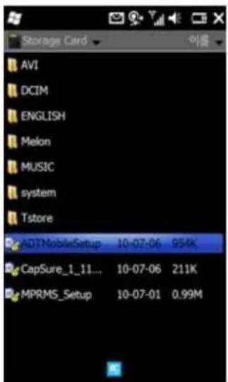
Execute the "MPRMS_Setup.CAB" le then "MPRMS" icon will be created on the screen.
Chapter 17. Mobile and Remote Client Applications
3. Windows Mobile

You can see the icon of "MPRMS".
Register the Product Informaon on Windows Mobile
For mobile viewing, you must register the network informaon of the DVR. As for the network seng of DVR, please refer to the user's manual of DVR.
[1] Register
Click the "Add DVR" to register a new DVR.

[2] Fill in the required informaon.
Chapter 17. Mobile and Remote Client Applications
3. Windows Mobile

Enter info. like the picture above.
• NAME : Input any name you want.
• ID : Enter the DVR's login ID.
- PASS: Enter the DVR's login password.
- MODEL: Select the spec. of the model among H.264, MPEG-4 and MJPEG.
[3] Enter DDNS info.
![INFO DONS [STATIC] Use DDNS ID : h4f4005b00000091 ADDR : 61.250.157.14 PORT : 2400 SAVE Cancel](/content/2026/05/1024313/images/99939834262a9cdc79d68e1798a6f5b6214d6d69a37487fddab97ab3c284808e.jpg)
DDNS seng is for a Dynamic IP user and should be entered as follows.
- Use DDNS: Select if you are a dynamic IP user.
Chapter 17. Mobile and Remote Client Applications
3. Windows Mobile
- ADDR : Keep the default value of the DDNS server address (Default: www.adtcapscctv.net)
- PORT: The port value will be changed automacally. Keep the value as it is.
- SAVE : Save the info.
[4] Stac IP User

- Use STATIC : Select if you are a sta c IP user.
- ADDR : Enter the sta c IP address registered in the DVR
- PORT : Enter PORT registered in the DVR. (Default : 3000)
Connect / Disconnect on Windows Mobile
[1] Connect
Chapter 17. Mobile and Remote Client Applications
3. Windows Mobile

- Connect : Click the "Connect" to see the video.
- Info Setup : To change the DVR informa on, click the "Info Setup".
- 1 Only: When selected, it transmits a sll image with the certain interval in case the video streaming is interrupted due to the network load.
[2] Disconnect
- Disconnect: If you want to disconnect, click it.
[3] Change the channel

- CH : Click the “▼ to change the channel.
[4] Change the DVR
Chapter 17. Mobile and Remote Client Applications
3. Windows Mobile

To connect the other DVR, click the "DVR" and select the registered DVR in the "DEVICE". A er selec ng the DVR, click the "Connect" to see the video.
Search on Windows Mobile
![Data Send Out [1fps][5byte] DVR Connect Search PanTilt Zoom/ Rec Info Req START LIVE 10-07-06 08:07:55](/content/2026/05/1024313/images/836450fdb1e70af2caa0c8fa984169879da00a328197b987174821c183216684.jpg)
To play the recorded image, select "Search" then click "Rec Info Req" to set the date and me for searching. A er se ng the data and me, click "START" to play.
(NOTE : The playback can be delayed depending on the network environment)
PTZ Control for Windows Mobile

Click "Pan Tilt" to control the PTZ camera. Press the direcon buon to move the camera posion. [NOTE: In order to stop moving, user must press the "STOP" bu on.]
• Le : Move to the le
• Right : Move to the right.
- Up: Move to the upper.
- Down: Move to the down.
- STOP: Stop the movement.
• Normal/Invert : Change the direc on.
Zoom /Focus

Click "Zoom/Focus" to control zoom In/Out and Focus In/Out.
Preset
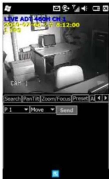
You can save the camera locaon previously and then send the camera to move to a specied pre-posion.
- P1\~P16 : Select numbers to save
- MOVE / SET
◎ MOVE : A er selec ng a number among from P1\~P16, press "SEND" to move the camera to the specied pre-posion.
◎ SET: A er selec ng a number among from P1\~P16, press "SEND" to set the loca on of camera.
Remote Alarm Control for Windows Mobile

Click "Alarm" to control alarm output.
- Select a number (1\~16): Relay out port. (Default: 1)
• Time : Set the dura on me.
• ON/OFF : Press to start or stop.
(Example: If the duraon me is set with 5 sec., the alarm output lasts for 5 seconds when you set it ON.)
Chapter 17. Mobile and Remote Client Applications
4. Internet Explorer Version 7 and later
4. Internet Explorer Version 7 and later
The monitoring by the web browser is available as the web server is built in the DVR.
Inial Connecon
If you have actual TCP IP address of the DVR you my input them directly into Internet Explorer or you may use the DDNS IP as indicated below.
Please check the network and port forwarding setup before starng the conncon.
[1] Visit hp://www.ddnsip.net to register your DVR.

① Enter the DVR's web code.
You can nd the web code as below.
Call the Menu → System → Informa on → Web code
② You can enter any name you want for your domain name.
③ Click "Register".
Also you can delete your registered DVR aer entering the web code and domain name.
Note
Chapter 17. Mobile and Remote Client Applications
4. Internet Explorer Version 7 and later
It takes around 10 to 15 minutes to get the service aer the registraon. So, please try the conneccon 10 to 15 minutes later.
[2] How to connect
Run the web browser on PC screen and enter hp://soon.ddnsip.net to connect.

In the rst connec on, install "Ac veX". If the Ac veX is installed, then DVR IP and DVR Port is set as a default value by itself. So if you enter the user ID and password, you can connect to the DVR.
Chapter 17. Mobile and Remote Client Applications
4. Internet Explorer Version 7 and later
Display Conguraon

(1) Display area: Whenever you click, the selected channel or split screen is displayed.
(2) DVR Name: Enter any name you want. When you reconnect the DVR in the same pc, the name is saved.)
(3) DVR IP : The IP address registered to the DVR automacally is displayed.
(4) DVR PORT : The port registered to the DVR is automatically displayed.
(5) USER ID : Enter DVR's user ID
(6) USER PW : Enter DVR's password
(Note : The Password is saved when you reconnect the DVR in the same pc.)
(7) CONNECT / DISCONNECT
(8) SETUP : You can set the DVR remotely.
(The remote setup is the same with the local setup.)
Chapter 17. Mobile and Remote Client Applications
4. Internet Explorer Version 7 and later
(9) BACKUP: It's available to back up the live or playback video.
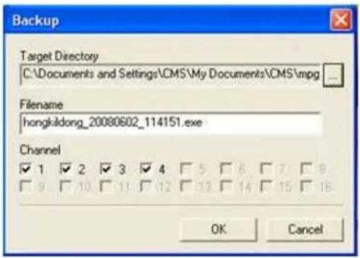
- Directory : Selects the folder to save.
- File name : Enter the le name to save.
• Channel: Select the channel to back up.
(10) JPG : Capture the current picture with jpg le and show the saved folder with popup message.
(11) BMP : Capture the current picture with BMP le and show the saved folder with popup message.
(12) SEARCH: You can search the recorded video remotely. The remote search is the same with the local search.
(13) Direcon key: You can use it when controlling the PTZ.
(14) CHANNEL : Select the channel connected to a PTZ camera.
(15) ZOOM : Adjust the zoom
(16) FOCUS : Adjust the focus
(17) IRIS : Control the IRIS
(18) TOURING : Select On or O for PTZ touring
Chapter 17. Mobile and Remote Client Applications
4. Internet Explorer Version 7 and later
(19) SPEED : Control the PTZ speed
(20) AUDIO : Select the audio channel to listen
(21) GDI : Display the video with GDI type (It increases the system load and it's recommended for the PC built-in the VGA card of high spec.
(22) RGB : It displays the pictures with the graphic card accelerator. It can decrease the system load but the picture quality is varied depending on the graphic card.
(23) MAX VIEW : Full screen func on (Enter "ESC" to go back.)
Index
10-way terminal block, 17, 20, 27
16 Channel DVR Storage Reference, 97
2CIF, 17, 18, 91, 92, 96
352X240. See CIF
352X288. See CIF
4 Channel DVR Storage Reference, 95
704X240. See 2CIF
704X288. See 2CIF
704X480. See D1
704X576. See D1
9 Channel DVR Storage Reference, 96
9 pole D-Type male connector. See RS-232
Acronym Denion
AGC, 122
BNC, 23
CMS, 105
DDNS, 107
DHCP, 51
DMZ, 52
D-sub, 21, 24
DTE, 32
DVR, 10
GUI, 68
HDD, 14
IP, 106
ISP, 51
LED, 14
MAC Address, 72
PGM, 31
PRMS, 105
S.M.A.R.T., 14
SMTP, 110
VGA, 20
administrator, 32, 34, 44, 72, 79, 107
alarm out, 29
Alarm Output, 17, 27
Alarm Sensor Extension Box, 26, 27
Android, 105, 179, 180, 181, 182, 183, 184, 186, 187, 188, 189, 190
Audio Input, 20
Audio Out, 20
Auto Delete, 77, 88
Auto Key Lock, 47, 89
auto locking, 44
Auto Loss Skip, 134, 137
AVI, 168
backup, 53, 87, 88, 147, 159, 160, 161, 163, 164, 165, 167, 168
Backup, 36, 43, 45, 66, 84, 159, 160, 161, 164, 165, 166, 167
Baud Rate, 129
Blackberry, 105
BNC, 17, 20, 23, 24
Brightness, 122, 123
Calculang Storage, 94
Calendar, 18, 63, 66, 147, 148, 149, 151, 161
Camera Input, 20, 24
Cauon
circuit overload, 12
cleaning unit, 12
cover o, 12
improper upgrade, 12
maximum temperature, 11
noise, 13
odor, 13
Product Weight, 18
Sensor Voltage, 28, 31
Shock, 13
side clearance, 11
venlaon, 13
vibraon, 13
voltage tolerance, 12
wall clearance, 11
CIF, 17, 18, 91, 92, 96, 108
class A IP address, 51
class C IP address, 51
CMS, 108, 128, 177
Congure Port, 52
Conguring User, 86, 87
Contents of Items Included, 15
Contrast, 122, 123
Covert, 88, 122
DDNS, 17, 72, 107, 108, 109, 112, 113, 172, 181, 189, 193, 194, 200
DDNS OPTION, 108
DDNS services, 112
DE-15F. See VGA
DE-9M. See RS-232
default admin password, 44
Default Seng, 79
De-Interlacing, 158
DHCP, 17, 33, 34, 51, 106, 107, 108
Dimension, 18
Direconal Buon, 36
DMZ, 52, 113
dry contact, 29, 30
dry sensors, 31
Dual Stream, 108, 121
DVR ID, 70, 172
EIA/TIA E568B, 33
email nocaaon, 110, 120
Email Nocaon, 120
email server, 110
EMERGENCY, 38
Emergency Lock, 47, 90
Error List, 77
Ethernet Pin Conguraon, 33
Ethernet port, 20, 32
Ethernet port details, 32
event recording, 98, 100, 151, 154
Event Recording, 49, 98
EVENT RECORDING, 49, 98
F/W Version, 72
Factory Reset, 44
Factory Seng, 79
Fast Play, 155
Firmware, 10, 72, 83
Focus, 130, 131, 185, 186, 197
frame, 94, 96, 98, 99, 108, 121, 158, 183
frame view, 158
Frontal Keypad, 43
Gain. See Gain control
Gain Control, 122
AGC, 122
Stac Gain, 122
Gateway Address, 107
GUI, 55, 68, 69, 72, 73, 79, 80, 83, 84, 86, 89, 98, 100, 102, 103, 106, 110, 112, 113, 120, 121, 122, 123, 124, 126, 127, 128, 129, 132, 134, 139, 140, 141, 143, 144, 145, 146, 148, 151, 160
H.264 compression, 91, 92
H/W Version, 72
HDD, 14, 15, 18, 44, 49, 54, 73, 74, 76, 77, 78, 81, 86, 88, 90, 91, 94, 95, 96, 97, 120, 133, 140, 148, 161
HDD Format, 76
Hue, 122, 123
image tear, 158
Internal IP address, 51
IP address, 33, 34, 51, 106, 107, 108, 109, 194, 200, 202
iPhone, 105, 169, 174, 177
ISP, 51
Labeling Camera, 48
MAC address, 72
Main Disk, 76
Mark In, 159, 160
MAX, 18, 28, 156, 204
maximum cable length for Category 5e, 32
menu tree, 55
Mirror Disk, 76
Modifying User, 87
Mouse Only Operaon, 157
Mouse operaon, 147
Mouse Sensitivity, 71
N/W Version, 72
Network Frame, 121
Network Port. See Ethernet port
Normally Open, 26, 27, 29
NTSC, 17, 18, 24, 71, 91, 92, 99, 189
Numeric keypad, 46
ODD, 18, 37, 74, 75, 77, 161
Operang Temperature, 18
PAL, 17, 18, 24, 71, 91, 99
Pan, 130, 131, 197
password, 44, 45, 46, 47, 86, 87, 110, 114, 120, 165, 172, 193, 201, 202
PGM output, 31
Playback Controls, 154, 157
Power
overload, 12
POWER OFF, 11, 14
POWER ON, 14
Uninterruptable Power Supply, 12
UPS. See Uninterruptable Power Supply
voltage tolerance, 12
Pre Recording, 98
Private IPv4 address. See Internal IP address
PRMS, 105, 108
PTZ, 20, 28, 29, 36, 38, 40, 43, 45, 53, 67, 88, 105, 122, 123, 124, 125, 126, 128, 129, 130, 131, 174, 177, 178, 184, 185, 186, 197, 203, 204
QUAD, 36, 38
Quick Backup, 160
Recording Frame Speed, 17
Recording Resoluon, 17
Rewind, 18, 36, 155, 156
right and le eld, 158
Right mouse click, 43
RJ-45 port. See Ethernet port details
Root Menu, 53, 55, 63, 66, 67, 68
Router, 34, 35
RS-232, 17, 24, 25
RS-485, 17, 27
SATA, 18, 74, 75
SCHEDULE RECORDING, 100
Search, 18, 36, 43, 63, 64, 65, 88, 105, 147, 148, 151, 152, 153, 169, 174, 175, 187, 196
Search Buon, 147
Sensor, 17, 18, 20, 26, 27, 28, 29, 30, 31, 40, 100, 101, 102, 103, 120, 139, 140, 145, 146, 152, 154
space allocaon in HDD, 49
Split, 53, 54, 132, 133, 134
SPLIT / SEQUENCE, 134
SPOT, 17, 20, 23, 143
Stac IP, 17, 51, 194
Subnet Mask, 107
S-Video, 17, 20
TCP/IP. See IP Address
Technical Specicaon
Audio, 17
Operang System, 17
Video Recording Compression, 17
Video Transmission Compression, 17
Temperature
maximum temperature, 11
operang temperature, 11
Tilt, 130, 131, 197
me bar, 150
me server, 82
Touring Mode, 125
TV ADJUSTMENT, 138
UI Version, 72
USB memory, 20, 32, 53, 83, 84, 85
USB Port, 20, 32, 37
Use Port, 110
User Group, 87
VGA, 17, 20, 21, 22, 40, 138, 204
Video Quality, 92, 108
View Control, 157
viewer, 165, 167, 174
Web Server Port, 108
Webcode, 72, 112, 113, 181, 189
Weight, 18
wet sensors, 31
Windows Mobile, 105, 191, 192, 194, 196, 197, 199
Zoom, 130, 131, 185, 197
- System Users Manual
- Table of Contents
- Contents
- Chapter 4. Main Menu (Root Menu)....53
- Chapter 5. The "System" Root Menu Item .... 55
- Chapter 6. The "Search" Root Menu Item....63
- Chapter 7. The "Backup" Root Menu Item....66
- Chapter 8. The "ER", "PTZ", and "Sound" Root Menu Items....67
- Chapter 9. Systems Secon In-Depth ......68
- Chapter 13. Display Secon In-Depth....132
- Chapter 14. Event Secon In-Depth ...... 139
- Chapter 15. Search Operaon ....147
- Chapter 16. Backup Operaon....161
- Chapter 17. Mobile and Remote Client Applicaons ....169
- Chapter 1. Preface
- About This Guide
- Precauons - Before You Start!
- Precauons – Aer Powering On!
- Precauons – Roune Maintenance!
- Contents of Items Included
- Chapter 2. Hardware Descripon
- Technical Specicaon
- Chapter 2. Hardware Description
- Technical Specification
- Rear Port Specification and Connection Examples
- Rear Port Specicaon and Connecon Examples
- Power input
- VGA (Video Graphics Array) Port
- Main Monitor Output
- SPOT Monitor Output
- Camera Input
- RS-232 Serial Connector
- Oponal Alarm Sensor Extension Box
- 10-Way Terminal Block
- Warning
- RS-485 Connecons
- Alarm Out
- Sensor Input
- Example 1. Dry contact sensor direct to DVR
- Example 2. Dry contact and 12 Volt DC combinaon direct to DVR
- Example 3. Alarm panel integraon with Dry and Wet sensor.
- USB Connecon
- Ethernet Port
- Ethernet Specicaons
- Front Panel
- Remote Controller
- Chapter 3. Quick Setup
- Placement
- Connecon
- Connection
- Quick Power On
- Inial Boot
- Setup Screen
- Change Password and Enable Auto Lock
- Labeling Camera
- Enable Recording
- Prepare Network
- Chapter 4. Main Menu (Root Menu)
- Main Items.
- Sub operaonal items.
- Chapter 5. The "System" Root Menu Item
- Convenon of Menu Tree
- The "Record" Branch
- The "Network" Branch
- The "Camera" Branch
- The "Display" Branch
- Chapter 6. The "Search" Root Menu Item
- The "Calendar" Search Branch
- The "Event" Search Branch
- The "Date / Time" Search Branch
- Chapter 7. The "Backup" Root Menu Item
- Chapter 8. The "ER", "PTZ", and "Sound" Root Menu Items
- Chapter 9. Systems Secon In-Depth
- INFORMATION GUI
- Language
- Remocon ID (Remote Controller ID)
- Mouse Sensitivity
- Video Standard
- MAC Address
- Webcode
- Versions
- DISK MANAGER GUI
- Adding, installing HDD and other drives
- Installing ODD (Opcal Disk Drive)
- CD / DVD RW
- Overwrite
- Auto Delete
- Error List
- Chapter 9. Systems Section In-Depth
- S.M.A.R.T(Disk Management)
- DEFAULT SETTING GUI
- TIME / DATE GUI
- Conguring Year/Month/Day
- Conguring Date & Time
- Conguring Daylight Saving Time
- Conguring Time Server
- UPGRADE GUI
- Conguraon Download
- Conguraon Upload
- PASSWORD GUI
- Conguring User ID
- Modifying User Informaon
- Conguring User Authority
- Conguring Network Covert
- BUTTON SETTING GUI
- Conguraon of audible beep
- Conguraon of Auto Key Lock
- Conguraon of Emergency Lock
- Chapter 10. Record Secon In-Depth
- Compression, Resoluon, Quality, and Speed of Video
- Video Compression
- Video Resoluon
- Chapter 10. Record Section In-Depth
- Compression, Resolution, Quality, and Speed of Video
- Video Quality
- Speed of Video
- Calculang Storage Required
- Channel DVR Storage Reference Chart
- Channel DVR Storage Reference Chart
- Channel DVR Storage Reference Chart
- Conguring Pre Recording
- Conguring Event Recording
- SCHEDULE RECORDING GUI
- Select the channel
- Set the recording schedule
- Copy
- HOLIDAY GUI
- Select holidays
- Delete
- Chapter 11. Network Secon In-Depth
- About Network Secon and Clients
- IP ADDRESS GUI
- DHCP (Dynamic Host Control Protocol)
- Note... What is port-forwarding?
- DDNS Address
- Transmission Opon
- What is the Dual Stream Funcon?
- Web Server Port
- Chapter 11. Network Section In-Depth
- E-MAIL SETUP GUI
- DDNS OPTION GUI
- Built in DDNS Server setup
- DDNSIP.Net example
- https://www.dyndns.com/confirm/create/7rlxBd8xrjmarhmoJrJJA
- EMAIL NOTIFICATION GUI
- NETWORK FRAME GUI
- Chapter 12. Camera Secon In-Depth
- CAMERA SETTING GUI
- PTZ SETTING GUI
- Additional PTZ seng
- CONTROLLER GUI
- CAMERA TITLE GUI
- PTZ TOURING GUI
- SERIAL PORT SETTING GUI
- How to operate PTZ camera
- Chapter 12. Camera Section In-Depth
- Chapter 13. Display Secon In-Depth
- OSD GUI
- 2.SPLIT / SEQUENCE GUI
- TV ADJUSTMENT
- Chapter 14. Event Secon In-Depth
- SENSOR GUI
- ALARM GUI
- MOTION DETECTION GUI
- SPOT OUT GUI
- Spot Mode:
- INTERNAL BUZZER GUI
- EXTENDED GUI
- Alarm Sensor extension box seng
- Chapter 15. Search Operaon
- Geng to Search Screen
- Calendar Search
- Chapter 15. Search Operation
- Event Search
- Date and Time Search
- Playback Control Menu Bar
- Playback Controls
- Play and Pause operaon
- Fast Play, Rewind Operaon
- Mouse Only Operaon
- View Interval Opon
- De-Interlacing Opon
- Audio in Playback Opon
- Quick Backup During Playback
- Chapter 16. Backup Operaon
- Note
- Calendar Backup
- Select the camera
- Chapter 16. Backup Operation
- Select the date
- Select the disk
- Select the hour
- Select the minute
- Set the backup start me
- Select the backup compleon me
- ▶ Select the backup opon
- Backup Size
- Backup Password
- Backup process
- Display Backup Completed
- Backup Viewer
- AVI conversion
- Chapter 17. Mobile and Remote Client Applicaons
- iPhone
- iPhone Applicaon Installaon
- Chapter 17. Mobile and Remote Client Applications
- Search from iPhone
- Controlling Relay-Out from iPhone
- PTZ control from iPhone
- Android Phone
- Program Installaon for Android
- Applicaon Execuon for Android
- Register the product informaon for Android
- Modify/Delete of Registered Informaon for Android
- Remote conncon for Android
- Live view on Android
- Main menu view on Android
- PTZ control for Android
- PTZ Preset for Android
- Search on Android
- Relay Out for Android
- Informaon display opon on Android
- [Display Info]
- End the conncon for Android
- Windows Mobile
- Execute the program for Windows Mobile
- Register the Product Informaon on Windows Mobile
- Connect / Disconnect on Windows Mobile
- Search on Windows Mobile
- PTZ Control for Windows Mobile
- Zoom /Focus
- Preset
- Remote Alarm Control for Windows Mobile
- Internet Explorer Version 7 and later
- Inial Connecon
- Display Conguraon
- Index
Brand : Clover Electronics
Model : DV1670D
Category : Dictaphone