
5J.J4V10.011 - Flat Screen Mount BENQ - Free user manual and instructions
Find the device manual for free 5J.J4V10.011 BENQ in PDF.


| Product Type | Flat Panel Mount |
| Brand | BenQ |
| Model | 5J.J4V10.011 |
| Compatible Screen Size | 32" to 65" |
| Maximum Weight Capacity | 50 kg (110 lbs) |
| VESA Compatibility | 100x100mm to 600x400mm |
| Material | Steel, Plastic |
| Product Dimensions (W x H x D) | 750 x 450 x 60 mm |
| Net Weight | 4.5 kg |
| Tilt Range | +5° to -15° |
| Swivel Range | ±30° |
| Rotation (Landscape/Portrait) | Yes |
| Distance from Wall | 60 mm |
| Installation Type | Wall Mount |
| Cable Management | Yes |
| Power Supply | Not required (passive) |
| Cleaning Instructions | Wipe with a soft, dry cloth. Avoid solvents. |
| Safety Features | Anti-tip design, safety lock |
| Spare Parts Availability | Contact BenQ support |
| Warranty | 2 years |
Frequently Asked Questions - 5J.J4V10.011 BENQ
User questions about 5J.J4V10.011 BENQ
0 question about this device. Answer the ones you know or ask your own.
Ask a new question about this device
Download the instructions for your Flat Screen Mount in PDF format for free! Find your manual 5J.J4V10.011 - BENQ and take your electronic device back in hand. On this page are published all the documents necessary for the use of your device. 5J.J4V10.011 by BENQ.
USER MANUAL 5J.J4V10.011 BENQ
- Please read and follow the instructions in this installation guide carefully before installation and retain them for future reference.
- The BenQ Corporation is not liable for any damage or injury resulting from incorrect installation.
-
The wall mounting bracket is designed for easy installation and removal. The BenQ Corporation accepts no liability for any damage or injuries due to human action or from natural causes, such as an earthquake or typhoon.
-
This projector wall mounting bracket must only be installed by service professionals.
-
At least two persons are required for the installation or removal of this bracket to prevent personal injury, or material damage from heavy falling objects.
-
To ensure proper ventilation, install the projector with sufficient clearance between it and the wall and ceiling.
-
To ensure safe installation and avoid accidents, check the wall structure and select a solid durable location.
-
The wall should be strong enough to support four times the total weight of the projector and the wall mounting bracket, or more. It should also be of sufficient strength to bear the force of vibrations from earthquakes or other events.
-
Check the surroundings of the mounting location before installation.
-
Do not install in places where the temperature or humidity is high and avoid moisture.
- Do not install near an air conditioner or vents, or in excessively dusty or oily places.
- This product must only be installed on a vertical wall, not a slanting one.
- Do not install in places subject to vibration or shock.
-
Keep the projector out of direct sunlight
-
Do not replace any parts or use damaged parts. Please contact your retailer if you have any questions.
-
Fix the screws tightly but not excessively to avoid breakage or damage to the threads.
-
The wall mounting bracket can support a maximum projector weight of 5J.J3A10.021: 15Kg or 33.07 lbs 5J.J4V10.011/5J.J4R10.011: 12Kg or 26.46 lbs.
-
Nothing extra must be added to the load on the wall mounting bracket. Nothing should be attached or hung from it.
-
Holes for the screws will remain in the walls after the projector mounting bracket has been removed and marks may also result from long term use.
| Packaged Parts | P.3 |
| Required Tools / Torque Adjustment | P.4 |
| Angle Adjustment | P.4 |
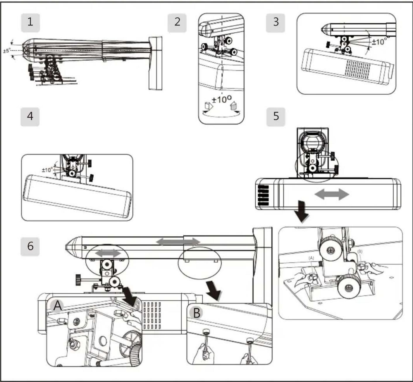
| 1. Adjust the mounting bracket arm of the projector to 5°.2. Adjust the rotation angle of the sides of the projected image.3. Adjust the angular displacement of the top and the bottom of the projected image.4. Adjust the horizontal angular displacement of the projected image.5. Move the base plate(A) inside the rails the rails (B) to enable projector horizontally lateral moves.6. Adjust the distance between the projector and the projected image: (A) Move the projector bracket.(B) or adjust the distance of the projection. | |
| Specifications / Size / Guide sheet for hole drilling | P.5 |
| Installation Steps | P.6 |
| 1. Installing the wall bracketA. Make sure the wall bracket (P) is in the correct position on the wall. Hold the bracket (P) firmly against the wall and mark the places for the holes with a pencil.Drill the holes at the marked points. The holes for a masonry wall should be 10mm (0.39") in diameter and 55mm deep (2.17"). Use a hammer to drive the plastic plugs (C) into the holes.For a wooden wall, drill 4.5mm (0.17") diameter holes 55m (2.17") deep.B. Screw the self-tapping screws (C) into the wall.C. Push the power cord into the front end of the projector main support member and pull it out at the back.D. Insert and secure the socket head screw M6 x L8 (F) in the holes of the projector main support member (Q) and the wall bracket (P) by using a 5mm hex wrench (K). It is necessary to leave a gap of 0.5mm for adjustment of the angle after assembly.E. Before positioning the hinge module (A), secure the socket head screw (H) in the projector main support member (Q) to enable the cantilever support to be in the horizontal direction. | |
| 2. Installing the fixing bracket on the bottom of the projectorA. Install the projector bracket (A) on the projector, using shim screws (I) and sleeves (J) to fasten these 3 parts onto the projector.B. Align the holes in the hinge connector (D) with those in the hinge module (A). Insert M6 x L10 (F) hex head screws into the holes and tighten them with Wrenches (K). Allow 2-3mm clearance for installing the bracket on the arm. | |
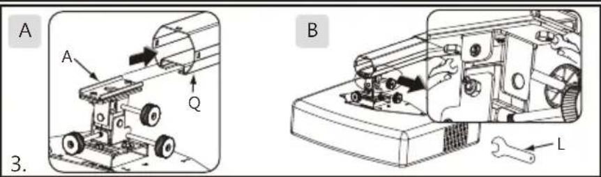
| 3. Installing the bracket on the bottom of the projector armA. Assemble the hinge module (A) and the projector main support member (Q).B. After attaching the projector bracket (A) to chassis (Q), tighten both with a wrench (L). | |
| 4. Cable ManagementA. Plug the power cord into the projector.B. Fit the plastic cap (M) to the end of the projector main support member (Q).C. Pass the power cord through the lower plastic cover (O) and then fit the upper (N) and lower (O) plastic covers as shown. | |
| 5. Adjusting the projection angleP.7A. Using a hex wrench (K) to adjust the tightness of the internal hex screws (H), the projector may be adjusted to the required angle.After adjustment to the required angle, tighten internal hex screws (F) using the 5mm hex wrench (K), then replace the upper and lower plastic cover (N)(O).B. The gray knob (A) is used to adjust the sideways rotation angle of the projected image.C. The yellow knob (B) is used to adjust the angular displacement of the top and bottom of the projected image.D. The black knob (C) is used to adjust the horizontal angular movement of the projected image.E. Move the base plate(A) inside the rails the rails (B) to enable projector horizontally lateral moves. | |
A
Hinge module_1pcs  | A
Hinge module_1pcs 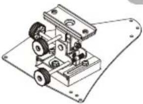 | ||||
C
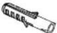 Plastic plug_6pcs
 | D
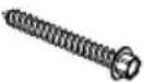 Tapping screw_6pcs
 | E
 | F
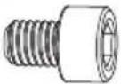 Hex bolts(M6 xL8)_4pcs
 | ||
G
 Hex Head Screws(M6 xL10)_2pcs
 | H
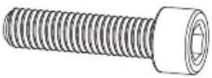 Hex bolts (M6xL25)_1pcs
 | I
 Shim Screws_4pcs
 | |||
J
 Height adjustment pipe _4pcs
 | K
 Hex key(5mm)_1pcs
 | L [Wrenches (10mm)_1pcs | M
 Cable management cap_1pcs
 | N
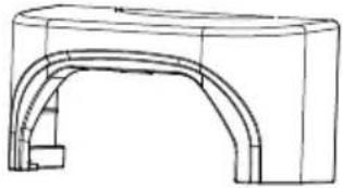 upper plastic cap_1pcs
 | |
O
 lower plastic cap_1pcs lower plastic cap_1pcs | P
 wall bracket_1pcs wall bracket_1pcs | ||||
 projector main pole_4pcs
 | |||||

- Power drill 2. Drill bit 3. Hammer
- Spanner: 8mm / 10mm5. Cross (Phillips) screwdriver 6. Pencil
Angle Adjustment
- Adjust the mounting bracket arm of the projector to ±5° .
- Adjust the rotation angle of the sides of the projected image.
-
Adjust the angular displacement of the top and the bottom of the projected image.
-
Adjust the horizontal angular movement of the projected image.
- Move the base plate(A) inside the rails the rails (B) to enable projector horizontally lateral moves.
- Adjust the projection distance: (A) Move the projector bracket. (B) or adjust the projection distance.
Ultra Short Throw Wall Mount (5J.J3A10.021)
| Connection plate | A |  |
| Material | Steel/Aluminum alloy | |
| Weight | 3.6 kg (7.93 lbs) | |
| Size (W x H x L) | 110 x 215 x 558mm | |
| Maximum distance from wall | 460mm | |
| Rotation angle | +/-10° | |
| Load | 15kg (33.07bs) | |
| Screw | M4 | |
| Tilt angle | +/-10° |
Ultra Short Throw Wall Mount (5J.J4V10.011)
| AConnection plate |  | |
| Material | Steel/Aluminum alloy | |
| Weight | 4.02 kg (8.86 lbs) | |
| Size (W x H x L) | 110 x 215 x 803mm | |
| Maximum distance from wall | 705mm | |
| Rotation angle | +/-10° | |
| Load | 12kg (26.46lbs) | |
| Screw | M4 | |
| Tilt angle | +/-10° |
Ultra Short Throw Wall Mount (5J.J4R10.011)
| BConnection plate | |
| Material | Steel/Aluminum alloy |
| Weight | 5.1 kg (11.24 lbs) |
| Size (W x H x L) | 110 x 215 x 1368mm |
| Maximum distance from wall | 1270mm |
| Rotation angle | +/-10° |
| Load | 12kg (26.46lbs) |
| Screw | M4 |
| Tilt angle | +/-10° |
Guide sheet for hole drilling
Please visit www.benq.com for the latest guide sheet for hole drilling
| Connection plate A | Mark A ==> MX880USTMark B ==> MX850UST / MW851UST | |
| Connection plate B | Mark A ==> MP772ST /MP776ST / MP782ST/ MX810ST/ MW811ST/ MX812ST / MX813STMark B ==> MW814ST/LX60ST/LW61ST/MX815ST/MX816STMark C ==> MP780ST/MW860USTi | |
Connection pl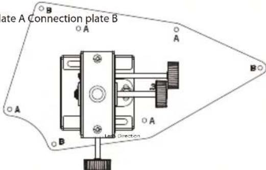 |  | |
Installation Steps
1. Installing the wall bracket
A. Make sure the wall bracket (P) is in the correct position on the wall. Hold the bracket (P) firmly against the wall and mark the places for the holes with a pencil.
Drill the holes at the marked points. The holes for a masonry wall should be 10mm (0.39") in diameter and 55mm deep (2.17"). Use a hammer to drive the plastic plugs (C) into the holes.
For a wooden wall, drill 4.5mm (0.17") diameter holes 55m (2.17") deep.
B. Screw the self-tapping screws (C) into the wall.
C. Push the power cord into the front end of the projector main support member and pull it out at the back.
D. Insert and secure the socket head screw M6 x L8 (F) in the holes of the projector main support member (Q) and the wall bracket (P) by using a 5mm hex wrench (K). It is necessary to leave a gap of 0.5mm for adjustment of the angle after assembly.
E. Before positioning the hinge module (A), secure the socket head screw (H) in the projector main support member (Q) to enable the cantilever support to be in the horizontal direction.
2. Installing the fixing bracket on the bottom of the projector
A. Install the projector bracket (A) on the projector, using shim screws (I) and sleeves (J) to fasten these 3 parts onto the projector.
B. Align the holes in the hinge connector (D) with those in the hinge module (A). Insert M6 x L10 (F) hex head screws into the holes and tighten them with Wrenches (K). Allow 2-3mm clearance for installing the bracket on the arm.
3. Installing the bracket on the bottom of the projector arm
A. Assemble the hinge module (A) and the projector main support member (Q).
B. After attaching the projector bracket (A) to chassis (Q), tighten both with a wrench (L).
4. Cable Management
A. Plug the power cord into the projector.
B. Fit the plastic cap (M) to the end of the projector main support member (Q).
C. Pass the power cord through the lower plastic cover (O) and then fit the upper (N) and lower (O) plastic covers as shown.



Installation Steps
5. Adjusting the projection angle
A. Using a hex wrench (K) to adjust the tightness of the internal hex screws (H), the projector may be adjusted to the required angle. After adjustment to the required angle, tighten internal hex screws (F) using the 5mm hex wrench (K), then replace the upper and lower plastic cover (N)(O).
B. The gray knob (A) is used to adjust the sideways rotation angle of the projected image.
C. The yellow knob (B) is used to adjust the angular displacement of the top and bottom of the projected image.
D. The black knob (C) is used to adjust the horizontal angular movement of the projected image.
E. Move the base plate(A)inside the rails(B) to enable projector horizontally lateral moves.

Brand : BENQ
Model : 5J.J4V10.011
Category : Flat Screen Mount