
SNMP Network Adaptor - Network card / adapter AEG - Free user manual and instructions
Find the device manual for free SNMP Network Adaptor AEG in PDF.


| Product Type | Network adapter / card |
| Brand | AEG |
| Model | SNMP Network Adaptor |
| Interface | Ethernet (RJ45) |
| Supported Protocols | SNMP v1, v2c, v3 |
| Data Rate | 10/100 Mbps |
| Power Supply | 5V DC, 500 mA |
| Power Consumption | 2.5 W |
| Dimensions (L x W x H) | 120 x 80 x 25 mm |
| Weight | 150 g |
| Operating Temperature | 0°C to 40°C |
| Storage Temperature | -20°C to 60°C |
| Operating Humidity | 10% to 90% (non-condensing) |
| LED Indicators | Power, Link, Activity |
| Management | Web interface, SNMP |
| Security | SNMPv3 authentication |
| Compatibility | Windows, Linux, macOS |
| Package Contents | Network adapter, CD with software, manual |
| Certifications | CE, FCC |
| Warranty | 2 years |
Frequently Asked Questions - SNMP Network Adaptor AEG
User questions about SNMP Network Adaptor AEG
0 question about this device. Answer the ones you know or ask your own.
Ask a new question about this device
Download the instructions for your Network card / adapter in PDF format for free! Find your manual SNMP Network Adaptor - AEG and take your electronic device back in hand. On this page are published all the documents necessary for the use of your device. SNMP Network Adaptor by AEG.
USER MANUAL SNMP Network Adaptor AEG
UPS WEB/SNMP MANAGER
SNMP Adapter
User Manual – English
Rel.52
Limited Warranty
This use of this product and the enclosed materials are provided without warranty of any kind. The entire risk as to software quality, performance of the program, media free of defects, faulty workmanship, incorrect use of the software or UPS, error free documentation and enclosed material is assumed by the user. We do not take any warranty to the correct functions of the software and the security of your system nor files, that might be damaged to due to possibly not correct function of our software. No warranty to correct functions of the software with the operating systems, loss of data or interruption of work processes, other UPS problems or to other errors that may occur out of this combination.
Copyright:
The information contained in this manual is non-conditional and may be changed without due notice. The software manufacturer undertakes no obligations with this information. The software described in this brochure is given on the basis of a license contract and an obligation to secrecy (i.e. an obligation not to further publicize the software material). The purchaser may make a single copy of the software material for backup purposes. No parts of this manual may be transferred to third persons, either electronically or mechanically, or by photocopies or similar means, without the express written permission of the software manufacturer.
The CS121 allows multiple server shutdowns only together with an RCCMD client license. This license is valid for using the RCCMD service on one server with one CS121 and an unlimited number of connected UPSMON-WINDOWS workstations. For shutdown of several servers a separate RCCMD license for every new server is required. The RCCMD service is generally delivered as a single license. Only 1 installation per license key is allowed. To use a single CD-ROM for several multiserver shutdown installations you have to purchase additional CD license keys.
Copyright of the European Union is effective (Copyright EU).
Copyright (c) 1994-2007 GENEREX GmbH, Hamburg, Germany. All rights reserved.
WEEE & RoHS: This product is compliant to the EU Directive WEEE 2002/96/EC, RoHS 2002/95/EC and the German implementation of the Electrical and Electronic Equipment Law. WEEE & RoHS conformity is registered at EAR under productname "CS121" and register no. DE 7733 7052.
RoHS: The product is leadfree and does not contain Lead, Cadmium, Mercury, Chrome VI, PBB polybromated biphenyl, PBDE polybromated diphenylether.
English Manual
This manual is also available in German!
To obtain an actual copy please see the download-page of www.generex.de
Contents
English Manual 3
1. The CS121 family - Introduction 6
1.1 About your CS121 6
1.1.1 General information 6
1.1.2 Functionalities of your CS121 6
1.2 About the communication with the CS121-Adapter 8
1.3 The CS121 Adapter Package 8
1.4 Comparison 10
1.5 CS121 overview 11
1.6 A typical installation - CS121 in a network environment 12
1.7 Connect your CS121 ... 13
1.7.1 ... via serial port 13
1.7.2 ... via LAN 14
1.8 Verifying the CS121 connectivity 14
2. Quickstart 15
2.1 Setting up basic network configuration 15
2.1.1 Using HTTP/Webbrowser 16
2.1.2 Using Telnet / MS-HyperTerminal 17
2.1.2.1 Building up a connection 17
2.1.2.2 Main menu & IP-Settings 18
2.1.2.3 UPS Settings 19
2.1.2.4 Save configuration 20
2.2 Adapter-restart and boot procedure 20
2.3 Introduction in the event configuration 20
2.3.1 About same basic events 21
2.3.2 Quickguide to install an RCCMD-job 21
3. Configuration of the CS121
3.1 CS121 Status-Monitors 23
3.2 Configuration 24
3.2.1 UPS Model & System 24
3.2.2 Network & Security 26
3.2.3 Email 27
3.2.4 Timeserver 28
3.2.5 Events / Alarms 29
3.2.5.1 Treshold events 31
3.2.5.2 Logfile entries 31
3.2.5.3 Email-Job 32
3.2.5.4 RCCMD Jobs 32
3.2.5.4.1 RCCMD Shutdown 34
3.2.5.4.2 RCCMD Message 34
3.2.5.4.3 RCCMD Execute/command 35
3.2.5.4.4 Example of use 1: CS121-adapter as RCCMD-listener 35
3.2.5.4.5 Example of use 2: CS121-adapter switches an output 35
3.2.5.4.6 RCCMD Trap 36
3.2.5.5 UPS shutdown 37
3.2.5.6 AUX-Port 37
3.2.5.7 Wake on LAN (WOL) 38
3.2.6 Scheduled Actions 38
3.2.7 SNMP 38
3.2.8 COM2 & AUX 39
3.2.8.1 COM2 39
3.2.8.2 AUX and SITESWITCH4 Settings 41
3.2.9 SENSORMANAGER 42
3.2.10 RAS Configuration 43
3.2.11 Save Configuration / Reboot 44
3.3 Reading the Alarm-Logfile 44
- Adapter Software-Updates (Firmware) 46
4.1 Firmwareupdate via Setup-tool 46
4.2 Firmwareupdate via FTP 46
4.3 Firmware flash renewal and recovery 47
4.4 Changing the Adapter's MAC-Address 48
- Additional Software 50
5.1 RCCMD 50
5.1.1 Installation 50
5.1.2 RCCMD client as relay station 52
5.1.3 License regulations 52
5.2 gChart 52
5.3 UPS Monitor (UPSMON) 53
- Accessories - Field of applications 54
6.1 SiteSwitch 4 (SS4) and SiteSwitch 4 AUX (SS4AUX) 54
6.1.1 SS4 Feature overview 55
6.1.2 SS4 Contents 55
6.1.3 SS4 Installation 55
6.1.4 SS4 Operation Error! Bookmark not defined.
6.1.5 SS4 - Technical data 56
6.2 Sensor SM_T_COM 56
6.3 SENSORMANAGER (SensorMan) 57
6.3.1 General information 57
6.3.2 Installation and Network integration 58
6.3.3 SENSORMAN connections 58
6.3.4 Configuration of the SENSORMANAGER 59
6.4 RASMANAGER 60
6.5 LED-Matrix Display 60
6.6 MODBUS / PROFIBUS 60
6.7 UNMS (UPS-Network Management System) 61
- Troubleshooting – FAQ 63
Appendix 64
A. CS121 - Technical data 64
B. CE- and UL-Certification 64
C. Cable and Circuit board configuration, Pin/AUX-Ports, SensorMan 64
D. MODBUS Interface 68
D.1. General information 68
D.2. Available Modbus Function Codes 68
D.3.Exception Codes 68
D.4. MODBUS Modes in the CS121 M (ASCII and RTU) 68
D.5. UPS Parameter 70
D.6. Bus termination 73
D.7. Configuration 73
D.8. TCP/IP - UDP Ports 73
D.9. MODBUS Cables 74
E. Available Variables of the CS121 74
F. Pin layout of Input-sockets of the SENSORMANAGER unit 75
Table of figures 77
1. The CS121 family - Introduction
1.1 About your CS121
1.1.1 General information
The CS121-series are a group of products designed especially for critical resource management within technical facilities. The CS121 can act as a UPS (uninterruptible power supply) manager for all other computers in the network. All of these products share many of the same basic CS121 features, and some have special components and functions. The CS121 products are most commonly used for the management of UPS systems, so in this manual we specially reflect to the usage of such devices with your CS121. All of the basic features and most of the product specific features and operation are explained in this manual. This manual is the basis also for other CS121 based products like CS121, CS121BUDGET, SENSORMANAGER, SM_T_COM, SITEMANAGER, SITEMONITOR, SITESWITCH4 und RASMANAGER.

Note: When using the CS121 to act as a UPS (uninterruptible power supply)
manager for other computers in a network it is necessary for those computers that are being managed by the CS121 to have its own RCCMD installation. RCCMD is the only possibility for enabling the communication between the CS121 acting as a UPS-Manager and other client computers in a network. While it is possible to add the different computers as clients in the CS121 settings it is only possible for those computers to act as an RCCMD client when they are running RCCMD. Each computer running RCCMD must have its own RCCMD license. This is the only possibility for the CS121 to fulfil its function as a network UPS (uninterruptible power supply) manager. Setting up the RCCMD commands is described in depth in the sections 2.3.2 Quickguide to install an RCCMD-job and 5 Additional Software.
There are several CS121 SNMP-adapters available for different UPS and although they are mainly made for UPS, the adapters can easily be modified by simply plugging in other products like the SITESWITCH SS4-AUX, SENSORMANAGER, and Modems in order to add new features.
There are two basic types of CS121-adapters: external and slot cards. The basic versions for UPS come without MODBUS-protocol, COM2 for environmental sensors and manageability and AUX for dry-contacts alarms. For more differences please see section 1.4 Comparison. There are other external products based on the CS121 such as the RASMANAGER, which is a CS121 with a built-in modem. Other external devices include the SiteSwitch 4 (for the direct control over power sockets), the SITEMONITOR 64 (for monitoring up to 64 digital alarms), and the SITEMANAGER 2 (a device with multiple functions) which are used for handling facility management purposes that go beyond the UPS systems.
Generally, the SNMP adapter runs an embedded Simple Network Management Protocol (SNMP) software agent. This agent responds to the SNMP operations "gets" and "sets" and also forwards "trap-messages" to designated recipients when critical conditions occur to the UPS - such as low battery status. Additionally, the adapter can send RCCMD signals to client computers running the Remote Console Command (RCCMD) initiating automatic shutdowns or other actions in case of an extended powerfail. (The RCCMD client is an extra system module requiring its own license.)
1.1.2 Functionalities of your CS121
- SNMP Adapter CS121/CS121 Slot: The SNMP adapter is a compact unit requiring minimal workspace (ca. 28x69x126 mm for the external adapter CS121L). The slot card versions of the adapter (CS111 and CS121SC) get inserted into the extension slots of UPS models supporting its card type.
- Serial Port: Two DIP-switches change the adapter's serial port (COM2) to a configuration port for installation or to a communication port for environmental sensors, modem or other
functions. The MODBUS-version uses the COM2 as RS485 and is not available for configuration. The MODBUS version can be configured only via Webbrowser, Telnet and Default IP address.
- SNMP-Traps for remote monitoring and pre-alarming: The main function of the SNMP-adapter lays in the transmission of alarm conditions of the UPS to the monitoring station (SNMP traps and RCCMD traps/commands). It also makes UPS data access able for users in the network upon request. With this function it is possible to retrieve and monitor eg. battery capacity of an UPS from an SNMP management station. The event settings configuration menu also allows for SNMP trap testing.
- Remote Control: With this function it is possible to switch the UPS to Bypass (depending on the model) or start battery tests. This remote command is executed either via the Network Management Station or the UPS Management Software or any Webbrowser.
- Telnet: Every Adapter maybe reconfigured via the network, using Telnet or http after the initial configuration of an IP Address for the adapter. Current UPS data can also be shown using Telnet. Generally we recommend to use the Webinterface since Telnet (and terminalconfiguration) does only allow to setup a basic configuration of the CS121.
- Works with all major NMS: The SNMP adapter works with most, widely used Network Management Systems e.g. HP Open View HP UNIX and Microsoft Windows NT, Novell NMS, Spectrum, Sun NetManager, IBM Net View/600 and others. All SNMP systems which either allow the compilation of the MIB or already incorporate MIB RFC 1628 for UPS Systems, can be operated with the Cs121.
- Multiserver shut down via RCCMD/RCCMD2 compatibility: The SNMP adapter CS121 is able to initiate a network shutdown with any RCCMD modules from the UPS-Management Software CD. A TCP/IP based RCCMD signal is sent to all RCCMD clients in the network. This enables the remote shutdown of practically an unlimited number of client computers, independent of which operating systems the clients are running. RCCMD is an optional part of the UPS-Management Software. Your UPS dealer is able to provide you with Licensekeys for the RCCMD. The UPSMAN service of the UPS-Management Software suite is an optional module and not needed for that basic CS121 operations. We recommend to use the UPSMAN service only if the UPS is connected via serial or USB cable, if a CS121 is connected only the UPSMON (optional OEm designed Windows interface) and the Webbrowser are needed.
- RS-232 UPS Protocol Router – Pipe- through: The CS121 (not BUDGET versions) is able to transfer the UPS RS-232 protocol on COM1 directly to COM2. This allows the use of additional monitoring software on COM2 while making extra hardware (RS-232 multiplexer) to multiply the UPS comport unnecessary.
- Logfile: CS121 has an internal logfile synchronized with either a set timeserver in your network or from timeservers in the internet. This logfile can be accessed through the Webbrowser, UPSMON, JAVAMON or via FTP. Due to the maximum file size of 250 lines (depends on Hardware, newer HW131 have 2-3 more space), old entries are deleted automatically.
- Network settings: The CS121 Models are adjustable to the network environment. An auto-sensing function 10 or 100Mbit can be activated.

Note: In large fast networks as is normally the case by CISCO or HP-Procurve
with auto-sensing switches problems can occur during the reboot of the CS121. If this is the case and switches are being used then the auto-sensing function might very well be the problem. Because the CS121 is per default set to auto-sensing (ON), this can lead to the network devices not being able to harmonise communication rates with one another. This auto-sensing process can take a long time and is sometimes never attainable. This taxes the CPU capacities of the switches and can greatly slow down the network or even lead ultimately to its failure. In this case a default network speed should be determined
and set after which, the CS121 can be changed from AUTO to the given speed, "100half" for example.
- Email client: The CS121 adapters incorporate a built-in SMTP email-client, which is able to send emails automatically in the event of an alarm.
- Web server: The CS121 Models contain a web-server, which displays all functions and settings of the adapter. Non-Windows users may use the JAVAMON as graphically display for UPS data (The JAVAMON module is not implemented in all versions.). Generally the CS121 Webserver is designed for the use with MICROSOFT INTERNET EXPLORER 6 with Active X and is recommended as configuration and management interface.
1.2 About the communication with the CS121-Adapter
- MODBUS
Modbus is the de facto standard protocol in industry which is used in the building surveillance and facility management. All CS121 types include an MODBUS over IP interface and MODBUS over RS232. The CS121 MODBUS types do not have an RS232 interface at COM2, here they use an RS485 interface. The CS121 BUDGET series does not support MODBUS. Please see the appendix where also output and protocol interface are shown.
• SNMP
The SNMP (Simple Network Management Protocol) is the Internet-standard protocol for managing devices on IP networks and is defined and standardized in Requests for Comments (RFCs)-specifications. UPS systems are using in generally as Management Information Base (MIB) the RFC1628-specification which defines UPS-specific devices.
The CS121 also comes with the standard MIB RFC1628. Because of this MIB is already part of most SNMP software products, it is not required to compile the MIB (Please search the MIB2 directory tree for a "UPS-MIB"). If you want to include your CS121-adapter to an SNMP-Management station, which does not have the standard MIB RFC1628, you can download the specific MIB from our website. (http://www.generex.de/e/download/cs12x/download_p.html) Copy the MIB file to the appropriate MIB-directory of your SNMP-station and compile this file. In most cases your SNMP already has implemented this MIB and a compilation is only necessary if you want to read extra information than just UPS (e.g. for SENSORMANAGER, etc.)
For additional information about MIB and NMS see also the section "UNMS" later on in this manual.
For the CS121-SNMP MIB Implementation, please refer to the GENEREX download-page http://www.generex.de/e/download/cs12x/download_p.html
This MIB is specially designed for the CS121 and includes SNMP values for all CS121 optional products (Temperature, humidity, alarm contacts, etc.) Basically this RFC1628CS121.MIB is the original UPS MIB, extended by extra values supported from your CS121.
- TCP
Most common way to communicate with the CS121-adapter is over TCP. CS121 includes UPSTCP, with gives you a complete interface to integrate the adapter into your network.
1.3 The CS121 Adapter Package
The standard CS121-adapter package contains an SNMP-adapter unit with supporting hardware and software. (Note, that the Budget-models do not have all features.)
Optional is a mounting kit for wall and DIN Rail mounting.
| Product Included | in delivery |
| CS121L(Extern) | Power supply external. (For USA/CA UL: Supplied by NEC Class 2 Power supply only) User manual English. Configuration cable for serial port configuration via Terminalsoftware - and for connection of optional devices for your CS121. |
| CS121SC(Slot Chinese) | User manual English. Configuration cable for serial port configuration via Terminal software - and for connection of optional devices for your CS121. |
| CS121F(Slot FUJI) | User manual English. Configurationcable for serial port configuration via Terminalsoftware - and for connection of optional devices for your CS121. |
| CS121R(SlotRIELLO/AROS) | User manual English. Configurationcable for serial port configuration via Terminalsoftware - and for connection of optional devices for your CS121. |
| CS121MOD(Extern) | Power supply external. (For USA/CA UL: Supplied by NEC Class 2 Power supply only) User manual English. Configuration cable for serial port configuration via Terminal software - and for connection of optional devices for your CS121. Mini-8 connector for your MODBUS RS-485 connection via COM2. |
| CS121BL(Budget Extern) | Power supply external. (For USA/CA UL: Supplied by NEC Class 2 Power supply only) User manual English. (Configuration only via networkcable) |
| CS121BSC(Budget Slot Chinese) | User manual English. (Configuration only via network cable ) |
| CS121 MODELS | FEATURES and OPTIONS | Supported UPS models | CS121 COMMON FEATURES FOR ALL MODELS * |
CS121L external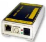 | Second mini din 9 COM port for RS232. AUX port for digital input/output. MODBUS RS485 option.Remote RAS management options. | All 1400 UPS models from over 60 different UPS manufacturers. | All CS121 devices are capable of managing the UPS models for which they are compatible via the UPS's native serial protocol. Each CS121 integrates seamlessly into all contemporary SNMP facility management systems.All CS121 models have their own web server with configurable event management for automating responses to power and UPS status conditions. This includes Emails transmission, RCCMD net work messages and shutdowns, logfile entries, grafical logfile for statistics, RCCMD Traps, UPS shutdown functions and wake-up calls for computers which have been shutdowned before (wake-on-lan).All actions and events may be configured individually.All CS121 have a built-in scheduler for regular tasks like battery tests, battery calibration and UPS shutdown/restore. |
CS121SC slot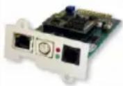 | Like CS121 L external. | All Chinese/Taiwanese standard slot UPS models. | |
CS121FFUJI slot | Second mini din 9 COM port for RS232. AUX port for digital input/output. Remote RAS management options. | FUJI UPS | |
CS121R Riello slot | Like CS121 F. Riello and Aros UPS | All CS121 have a wide range of network management features for alarming users and managing other SNMP devices and general overall Computer and Power resource management via RCCMD.All CS121s (except BUDGET models) include MODBUS-over-IP and an optional MODEM interface.All CS121s (except BUDGET models) offer a COM2 for connecting environmental sensors or for connecting other products and software to manage the UPS.All CS121 have 2 years warranty and a free update period of 3 years. All CS121 are made in Germany. | |
CS121BL BUDGET external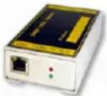 | Economic CS121 with LAN UPS management only.(No MODBUS over IP, no AUX port for dry contacts, no COM2 interface for modem or environmental sensors. | All 1400 UPS models from over 50 different manufacturer. | |
CS121BSC BUDGET slot | Like CS121 BUDGET External | All Chinese/Taiwanese standard slot UPS models. | |
1.5
CS121
overview
For CS121L, C and Slot card types
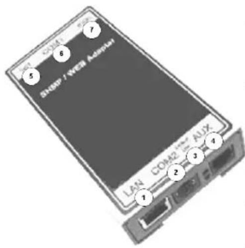
| No. | Description |
| (1) | Network connection RJ45 10/100 Base T Connector (with Status LED, green=link, yellow=activity) |
| (2) | Serial com-port (COM2) for configuration or connection of optional devices. (not BUDGET versions) |
| (3) | Error/Link LED UPS Status (Red=boot or error, Green (flashing) = normal |
| (4) | AUX Input/Output for dry contact alarms and relays |
| (5) | DIP-Switches for configuration mode |
| (6) | Serial port (COM1) for UPS connection (at BUDGET for terminal configuration) |
| (7) | (12V) DC Connection (Outside US : 9V-30V) |
Figure 1: Connectors of the CS121
CS121 family:
CS121L = external device with external power supply 9V (US: 12V)
CS121SC = slot device for Chinese UPS with slot (also as BUDGET, CS121BSC).
CS121F = slot device for FUJI UPS Japan
CS121R = slot device for RIELLO/AROS UPS Italy
CS121MOD = external device with MODBUS RS485 port
CS121CS MOD = slot device with MODBUS RS485 port
CS121BL = external device BUDGET-Model (does not have COM2- and AUX-port)
CS121BSC = slot device BUDGET-Model (does not have COM2- and AUX-port)
• (1) LED-Status of Network connectivity: The LEDs which are integrated into the RJ45 connector (see No. 1 in the figure above) will signal with green a connection to the network and with yellow network communication.
| Green LED Red LED Adapter | ||
| OFF | ON | Adapter is looking for UPS/initializing. The start phase can take up to 2 minutes |
| Flashing | OFF | Data flow/normal mode of the UPS |
| ON | ON | Communication to UPS interrupted |
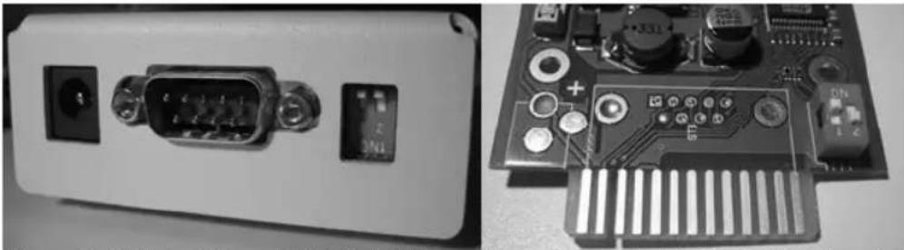
• (5) DIP-Switches: The DIP-Switches differentiate between two functions: Configuration- and normal mode.
natural_image
Two views of an electronic device showing a front panel with ports and a circuit board (no visible text or symbols)Figure 2: DIP-Switches: CS121L (left) in configuration mode (IP 10.10.10.10) and CS121SC (right) in normal mode
| Switch 1 Switch 2 Description | ||
| ON OFF Normal operation, device runs on the configured IP-address | ||
| OFF OFF Configuration mode with default IP Address 10.10.10.10 and active COM 2 configuration for Terminal SW |

Note: In the configuration-mode the full functionality of the CS121 is not provided! Please change to a valid network address and put DIP-switch 1 to position ON as soon as you made your basic network setting! After this, please continue configuring your CS121 in your network. Please follow up the procedure in chapter 2 Quickstart in this manual.
Additional information for CS121BL/CS121BSC: The BUDGET-versions do not have an external connection for COM2. This configuration interface has been routed to COM1 (UPS port).
• (7) Power supply: A power supply adapter (wall socket unit) (DC, 12V) provides power for the Adapter (external Model CS121L, CS121MOD, CS121BL only).

Note: If you are using a different power supply unit from the one in the adapter package, please consider that the polarity is set correctly. The adapter might be damaged if the wrong polarity is used. The power supply voltage should be at least 9V, 12 V is recommended.
For the CS121SC models C and the slot card, there are no power supply units. These units will receive power directly from the UPS device. The SNMP adapter C and slot card both incorporate a variable 9-36V input.
UPS Interface cable (extern devices only): Please use the manufacturer's serial port cable that came with your UPS to connect the UPS with the SNMP-adapter. Please contact your UPS manufacturer, if you have questions. Only use the original RS-232 UPS cable for communication, which was provided with the UPS. If your UPS has a contact closure port, please use the manufacturer's special cable. Please consult your UPS dealer on information regarding special cables.
1.6 A typical installation - CS121 in a network environment
A typical installation on the SNMP-adapter monitoring a UPS in an Ethernet network follows in the illustration below. The SNMP-adapter communicates with the UPS to inform you about your systems power condition.

flowchart
graph TD
    A["NMS (Network Management Station)"] --> B["IP Network (LAN/WAN)"]
    C["CS121"] --> D["UPS"]
    B --> E["Computer"]
    B --> F["Laptop"]
    B --> G["Computer"]
    B --> H["Power cable"]
    D --> I["Power cable"]
Figure 3: CS121 in a network environment
1.7 Connect your CS121 ...
In generally you can choose between 3 ways to configure the CS121-adapter:
- By using the serial port you can make the configuration via a Terminalprogram such as e.g. Microsoft-HyperTerminal. This configuration-mode allows you to make the fundamental settings for network connectivity and for defining the event and action-settings.
By using a LAN-connection you can make the configuration via Telnet or Webbrowser:
- The configuration via Telnet supports the same interface as the configuration via Terminalprogram.
- The configuration via Webbrowser allows you to make all kind of settings and configurations. If you have any possibility, we recommend you to configure the CS121-adapter via this way.

Note: External versions: At the CS121BL in configuration-mode a zero-modem cable (not included) may be connected to COM1. Please use a Terminal program to configure your CS121 via this connection. Option: At UPS with a DIP-Switch to configure between the UPS built-in serial port and outside serial port (e.g. UPS from PHOENIX TEC) you may insert the CS121BSC into the slot and use the original UPS cable for configuration via Terminal. We recommend to use the webbrowser as configuration interface.
1.7.1 ... via serial port
The SNMP adapter incorporates two serial ports (not BL and BSC-versions), whereas COM1 (see figure "Connectors of the CS121" above) provides the connection to the UPS and COM2 is used to configure the SNMP-adapter.
CS121BSC:
At the CS121BSC in configuration mode you can use the original UPS serial cable of the UPS and the in-built RS232 UPS interface to connect your CS121BSC via a Terminalprogram.
For the CS121BSC exists also the possibility to make the configuration via COM1. Therefore you have to set DIP-switch 1 in Position OFF and connect to COM1 port to the serial port of your workstation.
Configuration cable (not CS121BL/BSC):
Your package contains a configuration cable, which connects to the serial port (COM2) of the SNMP-adapter and the serial port of a PC with terminal software. It is sufficient to use a Dumb-Terminal or Terminal-Emulationprogram, such as e.g. Microsoft-HyperTerminal. During the
configuration of the SNMP adapter please ensure that the DIP switches are in the correct position. Please also refer to the section 1.5 CS121 overview in this manual.
1.7.2 ... via LAN
Connect the CS121 with RJ45 cable (not included) to your LAN.
1.8 Verifying the CS121 connectivity
After the CS121-adapter is connected to the UPS and to the Computer via serial port or via LAN, please verify the connectivity before you start to configure the CS121. The setup system can be checked before and after a configuration using the following 3 steps:
- UPS-Status displays (LEDs)
During the boot-procedure, the red LED is on, whereas the green LED is off. (Models with Hardware Version131 do also indicate uncompressing the firmware files with flashing red LED lightening) The boot process can take up to 3 minutes. If there is an error, the red LED does not go out. For more detailed information about the UPS-Status LEDs, please see section 1.5 CS121 overview.
After five to ten seconds after the boot-process, the green LED flashes rapidly; this indicates that the SNMP-adapter is trying to start the communication. The adapter will indicate its communication accessibility with random green LED flashes.
• Network status LEDs
The LEDs, integrated into the LAN-Connector (RJ45-), will signal a connection to the network with green and with yellow network connectivity.
• Ping the SNMP-Adapter
Perform a PING-command from the SNMP-station or from another computer in your network resp. NMS (Network Management Station).
If you do not get a response, check the SNMP-adapter network connection and IP-address of the SNMP adapter. The IP-address of the adapter is set to 10.10.10.10 if DIP-switch 1 is in position OFF (configuration-mode).

Note: The different response rates during the ping process do not correspond to an error. The adapter does not answer every ping signal at the same speed, due to different sized UPS protocols. If UPS protocols are of extensive size a timeout can occur briefly. A permanent timeout however is an error.
2. Quickstart
The Quickstart manual gives you a short instruction into the main features and how to make some basic settings and guides you in connecting the SNMP-adapter to the network and UPS.

Note: Before you start to configure the CS121 please ensure that your connections are valid as described in section 1.8 Verifying the CS121 connectivity (Red network-LED off; green network-LED flashing in intervals). Please take care that your UPS has been correctly installed before and is running!
There are three methods available for configuring the SNMP-adapter: Telnet, terminal and HTTP. These methods differ in the type of user interface and in the type of connection to be used for the configuration. The telnet method shares similarities with both, the terminal and the HTTP-method. Like the HTTP-method, the telnet method uses a network connection via the IP-address to establish a communication, but it has the same type of user interface as used in the terminal-method. The terminal-method requires that the SNMP-adapter be connected via the serial cable to a host computer. The terminal and telnet methods provide the user with a text menu indicating per alpha-numeric keys the possibilities for the user to either enter configuration commands or navigate through the menu levels. The HTTP-method provides the user with forms in which the system settings are either typed directly into a form or chosen per drop down menu.
Although, all of the configuration possibilities, Telnet, Terminal and HTTP are generally available, later in the parts of this manual only the explanation for usage of the HTTP-interface will be provided. We strongly recommend to use the HTTP interface for configuration and monitoring.
After you have completed the hardware setup and connected the SNMP-adapter, any of these three methods can be used to configure the adapter for the network. For this purpose depending on the configuration method, a communication must be established between the adapter and user via a serial terminal session or via an established network route in a telnet or HTTP session. CS121 allows a login only under the username "admin". Upon entering a telnet- or terminal-session with the adapter an authorization is required for which the default password is:
"cs121-snmp"
2.1 Setting up basic network configuration
The minimum requirement to operate the SNMP-adapter is to set the IP address, subnet mask and the UPS model:
- The DIP-switches of the SNMP-adapter firstly need to be set for the configuration. DIP-switch 1 is switched OFF in the top position as well as DIP switch 2 is switched OFF. Please note that the DIP switches of the SNMP-slot card adapter are situated on top of the circuit board and DIP switch 2 remains in the OFF position in configuration as well as in the normal mode.

Note: For slot versions you have to insert and remove the device for any reboot-process. This will not have any effect on your UPS but we recommend doing such operations only when the UPS is not supplying any load!
- As soon as the network-LED is flashing, add a TCP/IP route on your computer for IP-address 10.10.10.10. This is done via a call from your command line e.g. "route add 10.10.10.10
". See also route -? for more help of route syntax. - Test if you can ping the device now: Enter command „ping 10.10.10.10“ and check if there is any response. Now you can connect with any Telnet or HTTP-software and continue with the configuration.
2.1.1
Using
HTTP/Webbrowser
The entire configuration can be done via Webbrowser. Please use the default IP-address 10.10.10.10 and the TELNET password (default: "cs121-snmp"). The username is always "admin".
For the configuration using the webbrowser please observe the following:
We recommend the use of Microsoft Internet Explorer 6.x (or higher) or Mozilla 1.3x. Please note, that Java scripting has to be activated. Using Internet Explorer, the corresponding settings have to be made under "Internet options" - "security".
We also recommend never to use the history function of the browser, as this may lead to multiple transfer of commands (e.g. delete event jobs) to the adapter.
Upon entering a HTTP-configuration session, the user is required to enter a username, "admin", in addition to the password "cs121-snmp".
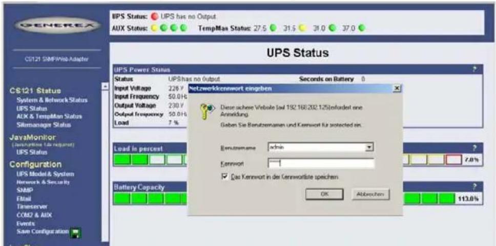
Figure 4: HTTP - Administrator login

Note: If the HTTP-method does not seem to be available, check to see whether or not the red LED UPS Status (see section 1.7 Connect your CS121 ...) is lit.
▶ Call Configuration, "UPS Model & System" and choose your UPS Model from the drop down list. Further configurations like Power, baud rate, cable type etc. were made automatically (ensure your Browser has enabled JavaScript) and do not need to be set. We strongly recommend to keep the default settings for this UPS unless you have instructions from the UPS maker.
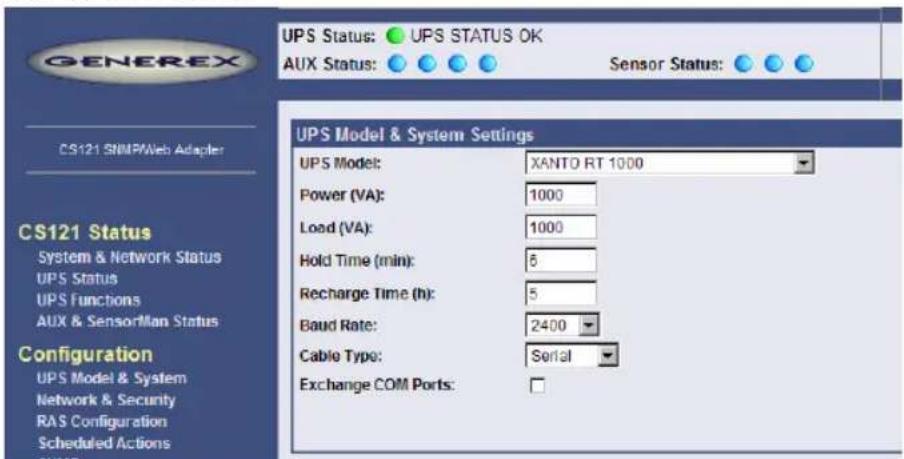
Figure 5: HTTP - UPS Model & System Settings
▶ Apply your settings with the button at the right side.
Change to menu "Network & Security" and specify IP-address, Gateway and Subnet mask to the CS121-adapter.
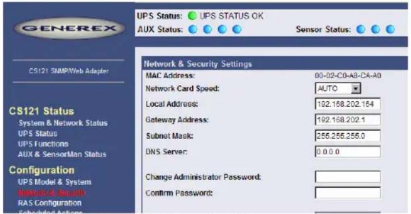
Figure 6: HTTP - Network & Security Settings
▶ Apply your settings with the button at the right side.
Change to menu "Save Configuration" and click "Save Configuration".
2.1.2 Using Telnet / MS-HyperTerminal
2.1.2.1 Building up a connection
Use of Telnet, enter the command: „telnet
Start a Terminalprogram (e.g. MS-HyperTerminal) and ensure that the serial communication cable for COM2 is connected. To build up the connection, mind the following communication settings:

| Adapter | |
| Baud rate 9600 | |
| Data bits 8 | |
| Parity | None |
| Stop Bits 1 | |
| Flow Control Xon/Xoff | None |
| Handshaking | None |
| CR/LF | OFF |
| Local Echo OFF | |
| Terminal Type ANSI (VT100) | |
Figure 7: Terminal communication settings
Please confirm this window with OK when you have done all settings. The Terminal is now ready for communication with the SNMP-adapter and the main menu will start after the password has been entered. (Default password is "cs121-snmp").

Note: The number of password-characters is limited in Telnet. Please do never use a password longer than 15 characters if you intend to use the configuration via Telnet!
2.1.2.2 Main menu & IP-Settings
![[ 1] IP Address, Gateway Address & SNMP System Group [ 2] Access Controls of SNMP Communities [ 3] Trap Receivers [ 4] UPS Settings [ 5] Event Settings [ 6] Network & Security Settings [ 7] COM2 & AUX Settings [ 8] Display Settings & Logfiles [ 9] Reset Configuration to Default [ U] Current UPS Status [ S] Save, Exit and Reboot [ Q] Exit without Saving Enter Command => _](/content/2026/05/1022523/images/bde928fef0c1c61730eb7c4d8a9b4304e2237647930c838a05235a2e791d953a.jpg)
Figure 8: Telnet - Main Menu
To select any option in the main menu enter the number of the option at the Enter command => prompt. The program displays the desired screen.
▶ Type 1 at the prompt and you enter the menu "IP Settings". Within this menu you can enter basic network configurations, e.g. IP-address, Gateway-address etc.
![Telnet 192.168.202.164 IP Settings Local Address: 192.168.202.164 Mac Address: 00-02-C0-A8-CA-A0 Gateway Address: 192.168.202.001 Subnet Mask: 255.255.255.000 DNS Server: 000.000.000.000 sysContact: sysName: CS-121 sysLocation: Attached Devices: UPS protected devices COMMANDS: [ 1] Set IP address [ 2] Set gateway address [ 3] Set subnet mask [ 4] Set DNS server [ 5] Set sysContact [ 6] Set sysName [ 7] Set sysLocation [ 8] Set UPS Attached Devices. (ex. 1 PC, 1 Printer) [ 0] Back to Main Menu EXAMPLE: to set the IP address to 128.100.90.57 => 1 128.100.90.57 Enter Command => _](/content/2026/05/1022523/images/41901f024337b18b7a7622000b7db06cdddec86198447e913d0d964934ff754e.jpg)
Figure 9: Telnet - IP Settings
To change values, enter the number of the option, type
For example: To assign the IP-address of the SNMP-adapter, the gateway and the subnet mask type at the prompt:
1,
▶ Enter Command => 1 192.10.200.0
▶ Enter Command => 2 192.10.200.254
Enter Command => 3 255.255.255.0
To assign the system contact name, type 5 and enter the name of the person to contact about the SNMP adapter.
▶ Enter Command => 5 Mr. Harry Hirsch
To assign the UPS name SysName, type 5 and enter name of the UPS:
▶ Enter Command => 6 USV 1
To assign the UPS location SysLocation, type 6 and enter the location name:
▶ Enter Command => 7 Building 12
2.1.2.3
UPS
Settings
▶ Choose option 4 from the main menu and you enter the menu "UPS Settings". Within this menu the user needs to select the UPS model the CS121-adapter is connected to (usually at COM1).
![[ 1] UpsModel : XANTO RT 1000 [ 2] Location : [ 3] Power (UA) : 1000 [ 4] Load (UA) : 1000 [ 5] Hold time(m): 6 [ 6] Recharge time(h): 5 [ 7] UpsID : 0 [ 8] Baudrate : 2400 [ 9] Battery Installation Date: 01.01.2005 [ D] System shutdown (minutes before battery end - downtime): 6 [ E] Exchange COM Ports: No [ 0] Back to Main Menu. COMMANDS: Enter 1 for a UPS-Model list. To enter a Model type 1 ,ex.: 1 1 selects No UPS Model def ined. To alter default parameters enter datafield number and value. ex.: 3 3000 sets Power to 3000VA ex.: 9 01.02.2002 sets Battery Installation Date to 1st of February 2002 Enter Command => _](/content/2026/05/1022523/images/e96a3354ceb6d06c9504a86aa49d02292836058c155a34ac22f78759386e9307.jpg)
Figure 10: Telnet - UPS Settings
The CS121-adapter distinguishes here generally between Cable- and Serial-models. With Cable, the adapter and the contact interface of the UPS are connected with a special cable. Using Serial, UPS models connect to the adapter via the serial UPS-cable. (Part of the UPS package). Serial is default, when the user selects a UPS model name from the drop-down list. When Cable is used, please search the list for the corresponding UPS model and cable type.
The CS-121 supports serial models with its own RS-232 protocol as well as contact UPS models with the cable types O,C,1-10. Those contact cables are UPS or alarm system specific and should be provided by the corresponding manufacturer. Our Cable documentation shows examples of those cables if they are individually made cables.
Please choose the corresponding Serial UPS model or Cable-model communication parameters. Parameters like baud rate etc. are preset for the corresponding UPS model.

Note: By selecting the UPS model, the communication protocol is selected at the same time. If your UPS does not appear in the list, ask your UPS dealer if another model from the same series can be substituted.
▶ Select Option 1 to get a variety of possible UPS models. After chosen a model, the default values of the corresponding UPS model can be configured by typing the number of the option followed by the value.

Note: Please do not change parameters except of UPS-model unless you want to choose specified configuration according your UPS-model!
Please note option "D": "System shutdown (minutes before battery end – downtime)": This value determines how many minutes before a complete battery unload the event "System shutdown" from event menu is executed.
The shutdown time interval needs to be set large enough, so that adequate time for a system shutdown is allocated before the UPS runs out of power. Please calculate this value generously e.g. if the battery time of the UPS is 10 minutes and the event procedure takes 2,5
minutes, ensure you start (configure) the shutdown (or other event action) 3 minutes before the UPS is switched off, so that more than enough time is available to complete the corresponding event action.
2.1.2.4 Save configuration
▶ Call “Save, Exit and Reboot”-command from the main menu. (The communication to the adapter will be lost).
ATTENTION: Keep the Telnet, Terminal, Webbrowser window open until the device has been lost or you see a message that reboot is under progress. If you close the configuration window too early it may corrupt the upsman.cfg configuration file. (see also section 4 Adapter Software-Updates (Firmware))

Note: Various options and settings for UPS-configuration can be done under Telnet or HyperTerminal, e.g. setting access controls of the SNMP-communities, set traps, set display settings, etc. However, the configuration via Webbrowser offers a much more convenient way to configure the CS121. If you have any possibility we recommend you to use this way.
2.2 Adapter-restart and boot procedure
▶ After you have finished the basic IP- and network-settings you should set DIP-switch 1 in position ON and restart the adapter with your configurations.
You can perform an adapter restart by unplugging the power supply of the CS121 and wait until the adapter has restarted with your configurations.
Alternatively you can restart the Adapter with the "Reboot"-Option in the "Save Configuration"-menu of the Webbrowser. The following message will displayed:
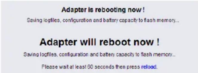
Figure 11: HTTP – Adapter reboot dialog
A successful restart of the adapter is indicated with the CS121 UPS- and network-LEDs as described in section 1.7 Connect your CS121 ....
▶ Reconnect your Webbrowser with the adapter using the configured IP-address. (e.g. http://192.168.10.123)
Your CS121-adapter is now ready for further configurations!

Note: If the adapter's HTTP-service is not available, check to see whether or not a red Status-LED is lit.
Further, test if you reach the adapter with a ping-command. Enter command „ping
2.3 Introduction in the event configuration
The configuration of the CS121 is based on events, whereupon an event can be an UPS-triggered event such as powerfail, battery low etc., and also events, which are released by the CS121-adapter, like events from the AUX-port or a connected SENSORMANAGER for example.
The CS121-configuration allows you to assign one or more actions to each event. An action can be to send an Email-notification to specific users as well as to perform a shutdown-signal
to several client stations. In addition, it is possible to specify when and how often an action is to be released.
2.3.1 About same basic events
Please call the menu "Events / Alarms" in the Web-browser to open the main configuration-site, whereon all configurable events are listed. In the following, we introduce same basic and important events which should be in general handled from every CS121-Adapter. For a complete description in-deep please see section 3 Configuration of the CS121.
- Powerfail
The event “Powerfail” will be released when the UPS has lost the power supply. This event is usually used to proceed operations like backup-strategies, batch-files to be executed on client stations etc. pp. You can configure such jobs with the “Remaining time”-parameter to ensure the actions will be executed completely.
- System shutdown
The event “system shutdown” will be released, if the configured “System Shutdown Time” (in the menu “UPS model and system”) is reached. This means, there are yet the configured minutes left until the battery’s capacity is expected to be finished (as calculated by the adapter).
This event should only be used to proceed all operations concerning your forced shutdown scenarios. Further operations are usually configured on the event "Powerfail".

Note: This EVENT is the final task a CS121 can initiate before the UPS switches off! DO NOT use this EVENT for triggering shutdowns via RCCMD etc. because the remaining time in this status is not secure. We strongly recommend to use the event “Powerfail” and configure the RCCMD shutdown calls with a UPS “remaining time”, this is the best way to send RCCMD shutdowns to several IP-addresses in a certain logic or sequence!
- Battery low
The event “Battery low” will be released from the UPS when the battery charge has reached a critical state.
- UPSMAN started
The event “UPSMAN started” is periodically released in normal operating mode. You can use this event to configure jobs, which should be executed as long as the adapter is working in normal mode.

Note: Same UPS models allows you to configure the thresholds for releasing UPS specific events individual. CS121 also supports these features if the UPS includes this possibility. See also section 3.2.5 Events / Alarms in this manual.
2.3.2 Quickguide to install an RCCMD-job
Condition for setting-up an RCCMD job in the CS121 configuration (like Shutdown for example) is the installation of RCCMD at the client workstation.

Note: Each RCCMD-Installation requires a licence key! Usually, the CS121 Adapter Package includes already one licence key. This license key can only be used once per installation. If more computers need to be added to the shutdown process, additional licenses are required.
Please follow the description in section 5.1 RCCMD to install RCCMD at the client-workstation.
After you finished the client-side installation of RCCMD you can configure an RCCMD-job at the CS121-adapter:
For example to configure a job, which initiates a shutdown-signal to a client-workstation, please enter the event "System shutdown" in the menu "Events / Alarms". The following "Event Editor" then lets you add a new job.

Figure 12: HTTP – Job Editor – Introduction
See the figure above, how to configure the RCCMD shutdown for a Client-Workstation. Note, that you enter the correct IP-Address of the Client.
Now the RCCMD shutdown procedure is already completed. Press the "Test"-Option in the Event Editor to verify your settings.
3. Configuration of the CS121

Note: After you have finished the basic network configuration you should have set DIP-switch 1 in position ON and rebooted the adapter. At the SC slot cards you have to remove the card from its slot and change the DIP Switch 1 to position ON. After this, re-insert the card. Info: There is no risk to remove/insert the slot card, there will be no effect on the UPS output.
3.1 CS121 Status-Monitors
The Menu "System & Network Status" shows basic information about general configuration settings:
System Info & Network Status
| System Information | |||
| CS121 Hardware | CS121-C-2003 | Location | |
| CS121 Firmware | CS121-SNMP v 3.51.4 | System Name | CS-121 |
| System Contact | |||
| HyNetOS Rel. 2.4 Gnd) - Mar 10, 2006PTange Server Rel. 3.4.5(g) - Mar 10, 2006DRIVER Generex CS121.B Rel. 2.4.25(Michael) - Jun 02, 2006Loader: BOOTMINTO-2(6Nk), ROM Version: 2.2.6(pk) - May 04, 2006 | Attached Devices | UPS protected devices | |
| System Time | 02.01.1070 05.29.51 | ||
| UPS Manufacturer | Online | Uptime | 0 days 4 hours 29 minutes 51 seconds |
| UPS Model | NANTO RT 1000 | Total Uptime | Approx 0 days 13.2 hours |
| Network Status | |||
| MAC Address | D0-02-CD-A8-CA-AD | Telnet Server | On |
| Network Speed | AUTO | HTTP Server | On |
| IP Address | 192.168.202.164 | Upsmon Server | On |
| Subnet Mask | 255.255.255.0 | Use RCCMD2 Traps | Yes |
| Default Gateway | 192.168.202.1 | SNMP Server | On |
| DNS Server | 192.168.202.1 | Use SNMP Coldboot Trap | No |
| Email Server | mail generes-gmbh.de | Use SNMP Authentication Trap | No |
| Time Server | 29.6.15.29 | Modbus Server | On |
Figure 13: HTTP - System & Network Status
The Menu "UPS Status" gives information about the actual UPS-data, above all the state of charge and battery load:
UPS Status
| UPS Power Status | |||||
| Status | UPS STATUS OK | ||||
| UPS Model | XANTO RT 1000 | Location | |||
| Input Voltage | 227 V | Seconds on Battery | 0 | ||
| Input Frequency | L1: 50.0 Hz | L2: 0.0 Hz | L3: 0.0 Hz | Battery Voltage | 41.60 V |
| Output Voltage | 230 V | Battery Capacity | 100.0 % | ||
| Output Frequency | N/A | Autonomy Time | 32.91 minutes | ||
| Load | 27 % | UPS Temperature | 27.8 | ||

bar
| Metric | Value | | ---------------- | ------- | | Load in percent | 27.0% | | Battery Capacity | 100.0% |Figure 14: HTTP - UPS Status
The Menu "UPS functions" allows you to perform USV test- and control-scenarios like battery tests, etc. The UPS functions depend on the UPS type and its functions. Some UPS only allow a remote on/off, others have more functions.
UPS Configuration / Test / Control Functions
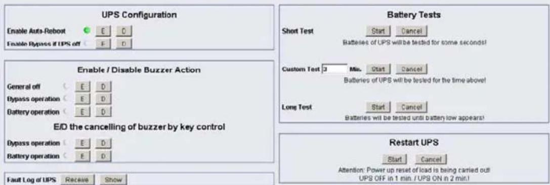
Figure 15: HTTP - UPS Functions
AUX & SensorMan Status:
The AUX & TEMPMAN status shows the actual measurements of the connected environmental sensor devices SM_T_COM, SENSORMANAGER or TEMPMAN.
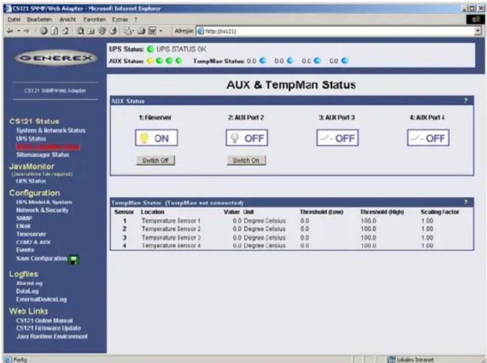
Figure 16: HTTP - AUX & SensorMan Status
In the above figure, a button menu is presented in which the ports 1 and 2 can be clicked on and off. A yellow light bulb indicates that output to the corresponding port is being provided, while the gray unlit light bulb indicates the status of being switched off in which case the connected device is not being provided with power. The buttons „Switch Off“ and “Switch On” are password protected. This is the same password that has been set in the CS121-configuration. The ports 3 & 4 are configured as input sensors, here the OFF symbol shows an open contact, and alarm would show a closed contact. The AUX port of CS121 can be configured as output or input – or a mixture of both.
3.2 Configuration
3.2.1 UPS Model & System
Use this menu to define the communication between the CS121-adapter and your UPS.
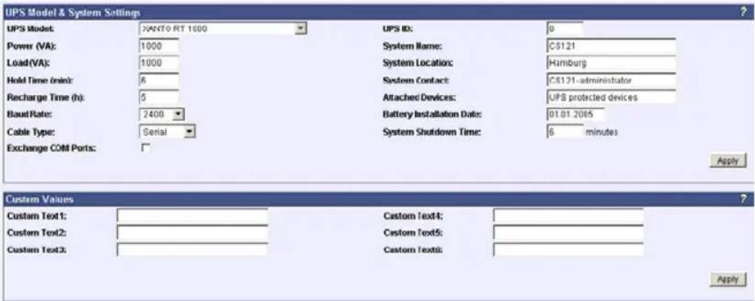
Figure 17: HTTP - UPS Model & System
With the parameters UPS ID, system-name, -location, -contact you can describe the UPS and CS121. This is useful e.g. to locate the UPS physically and can be used among others for event settings.

Note: Do not change the default UPS-Parameters for Baud Rate and Hold time unless you have special instructions from the UPS maker.
Please note the field "System Shutdown Time": This value determines how many minutes before a complete battery unload the event "System shutdown" from the event menu (please cp. according section 3.2.5 Events / Alarms) is executed. Attention: This EVENT is the final task a CS121 can initiate before the UPS switches off! DO NOT use this Event for triggering shutdowns via RCCMD etc. because the remaining time in this status is not secure. We strongly recommend to use the Event Powerfail and configure the RCCMD shutdown calls with a UPS "remaining time", this is the best way to send RCCMD shutdowns to several IP addresses in a certain logic or sequence!

Note: Please apply your changes before leaving the menu to send the values to the CS121-adapter - do not forget to press "SAVE & EXIT & REBOOT" after you have finished your configuration work!
The section „Custom Values“ contains 6 fields with can be used to save custom specific comments concerning your UPS.
3.2.2 Network & Security
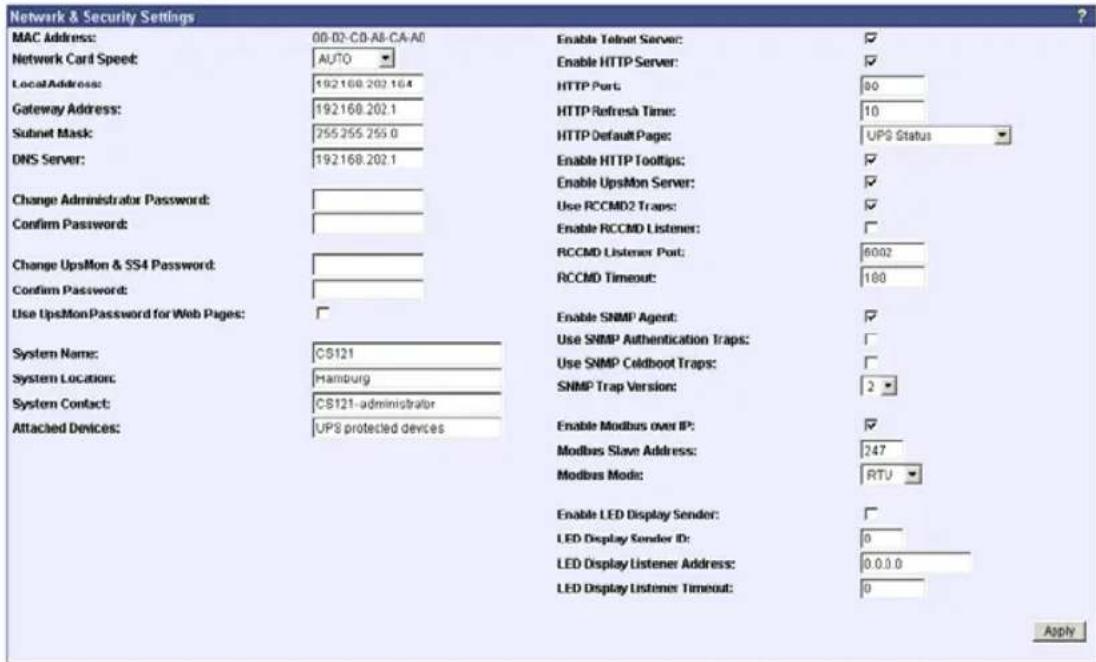
Figure 18: HTTP - Network & Security Settings
This menu configures the CS121 network card settings, passwords and enable/disables several adapter and network services.
Among others, here you can allow the CS121 to act as an RCCMD listener client. This makes it possible for another UPSMAN-Manager, CS121, SITEMANAGER or other RCCMD compatible sender to send the adapter an RCCMD command like sending one of the AUX output ports a high or low signal – or to start other actions.
You can also set the MODBUS configurations in this menu. The configuration requires only the following entries:
- Enable Modbus over IP: Every CS121 model with Firmware Version 2.0 (or higher) can also transfer UPS data via the MODBUS-protocol on IP (port 502). You may use any MODBUS client to read the UPS value from CS121. For using the RS-485 interface, you must use a CS121MODBUS (special hardware) in other cases you have to use MODBUS-over IP. This is enabled by default, you may disable this feature via Telnet or HTML-configuration.
- Modbus Slave Address: Enter the corresponding number, meaning which number in the chain (bus) the adapter is.
- Modbus Mode: RTU (Binary mode) or ASCII mode text output. Please select the type with the scroll down menu.

Note: ASCII Mode works with Parameters 7,N,1. The RTU Mode (binary) works with 8,N,1.
- Change Administrator Password: The password protects against unauthorized usage and manipulation. The default password is "cs121-snmp". In case you have "forgotten" your password a master password can be generated using your adapter serial number. Please contact your manufacturer for more information.
- Change UPSMON & SS4 Password: This is a separate password and allows to open UPS FUNCTIONS and SS4 FUNCTIONS only to specific users. With this password the user may switch on/off the UPS, start battery tests, switch SS4 outputs, but can not change any other setting on the CS121 configuration.
The UPSMON password blocks entry to the UPSMON tools battery test and emergency shut down. Knowledge of this password enable users to gain access to these security relevant functions.
3.2.3 Email
If you wish to define actions to send Emails depending on specified events you need to configure the Email settings.
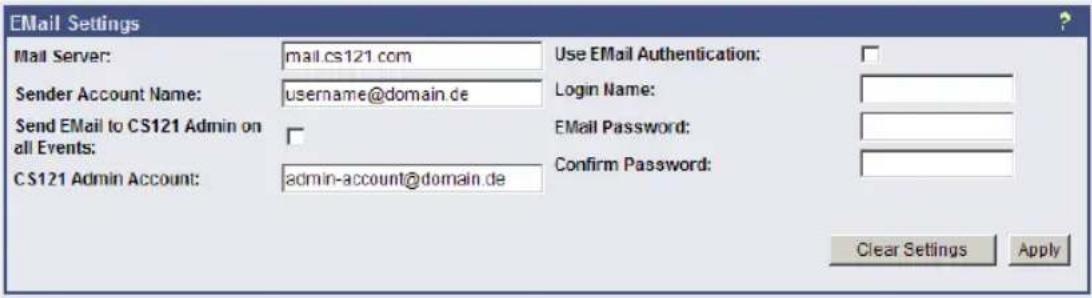
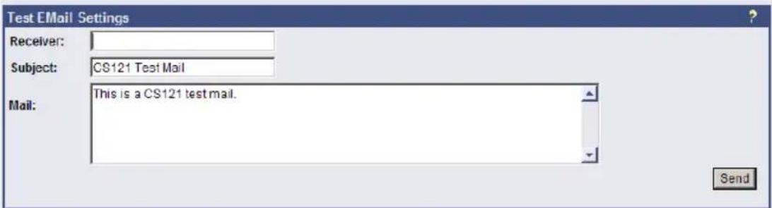
Figure 19: HTTP - Email Settings
In this menu the internet name of your SMTP mail client is required. If DNS is not configured, the actual mail server name's IP-address has to be entered. Please also note that the sender account name (e.g. ups@mailserver.de) should not be a random name since some Emailservers do not allow this. We recommend to use an existing account e.g. ups@mailserver.de. Most servers require matching account name and mail server names. E.g. someone@somewhere.com would be correct, whereas just "someone" would not be sufficient. If the server name and account name do not match, the following error message will be displayed in the CS121 alarm logfile (after some minutes): "Mail: bad answer from mail server: 501 UPSIP204@wrong server.com sender domain must exist."
The user can check the logfile if the email transfer works. The logfile (text.log under the adapter's root directory ../Flash/text.log) can be viewed using FTP, via the UPSMON tool or via the Webbrowser "Alarm log".
Mailservers outside the LAN require a username and password. For this function please use "email authentication" and enter a username and the corresponding email password (twice). Note: Do not use email authorization if this is not required by your mailserver!
If authorization is required, the email function "AUTH LOGIN" (the CS121 adapter supports only this function) needs to be supported. (e.g. Freemail.de). This changes the protocol from SMTP to ESMTP and a password is required.
The length of the password should be a minimum 3 and a maximum of 63 characters.
▶ Send a test-mail to validate your settings after you have applied the mail-settings. A short message on the menu indicates whether the test-mail could be sent or not.

Note: Please ensure that you have specified a DNS-server in menu "Network & Security" if the mail-server could not be reached.
3.2.4
Timeserver
The CS121 uses a timeserver to supply the correct date and time of any event in its local logfile. If no Timeserver is set, the CS121 will not use date and time in the logfile, but a date stamp of 1970. For the normal operation of the CS121 a timeserver is not required, but we strongly recommend to set access to a timeserver.
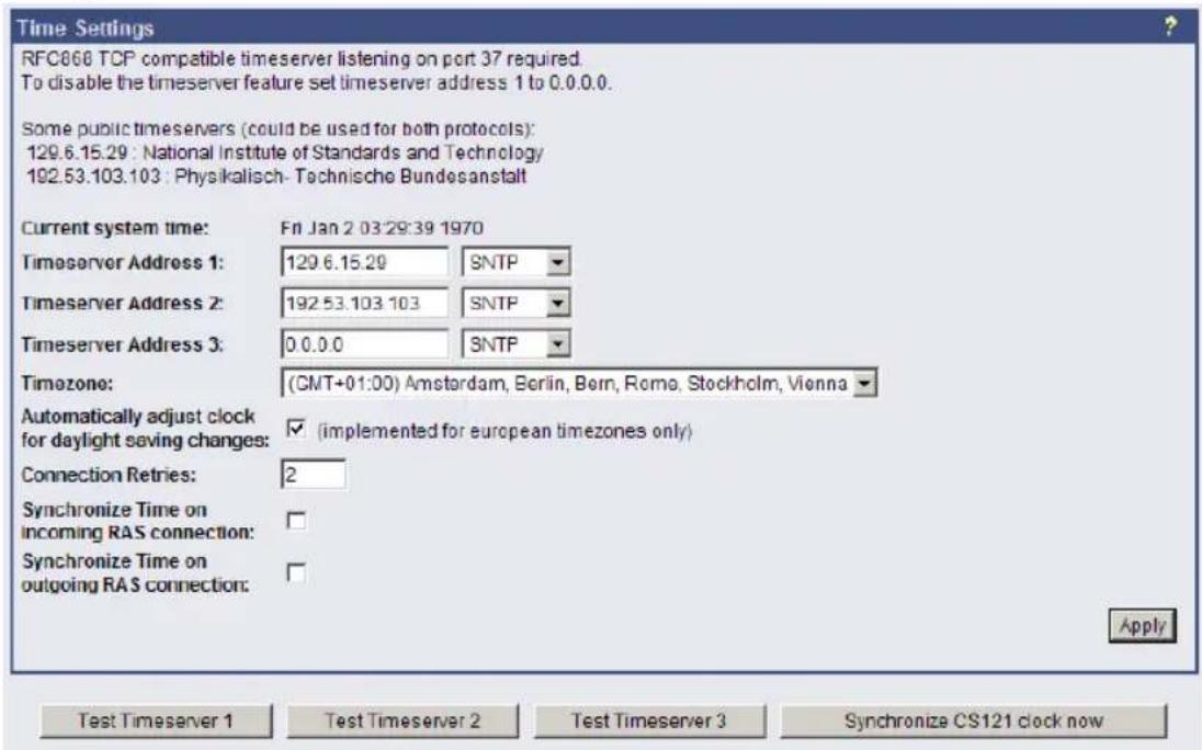
Test: timeserver:129.6.15.29 Wed Jan 10 16:59:16 2007 New settings applied.
Figure 20: HTTP - Timeserver Settings
The timeserver is important to synchronize the UPS logfile to the actual time. The adapter supports up to three different timeserver IP-addresses. Both, RFC868- and SNTP- protocols are available. Enter the IP-address of any timeserver in your LAN or in the internet. In the internet you will find many timeservers supporting RFC 868 TCP requests, e.g. the IP-address of the timeserver of the National Institute of Standards and Technology is 129.6.15.29; the timeserver of the Physikalisch-Technische Bundesanstalt is 192.53.103.103.

Note:
The timeserver will synchronize immediately following the reboot (featured with Firmware 3.03 and newer). If the synchronisation fails, the CS121 will attempt another timeserver synchronisation. Following that, the CS121 will attempt a synchronisation with the timeserver every 24 hours.
Every Windows computer offers the by "Windows Time" a timeserver which synchronizes the time of the PC with an internet clock. How to setup the MS-Timeservice is described below.
If you do not have any internet access in your network, you may setup a timeserver which use the PC clock. For this you may choose any freeware from the internet or download from here: http://www.generex.de/wwwfiles/timeserver/atcs22.zip
- Test Timeserver connection: This option is testing the Timeserver connection with a time and date stamp. Please note that the connection to the timeserver only works, when the adapter is not in the configuration mode (IP 10.10.10.10). The CS121 should have a timeserver to synchronize the UPS alarms with your local time. Without a timeserver the CS121 would use a default time from 1970.
- Microsoft Windows SNTP Timeserver: As timeserver you can use any e.g. Windows PC in your network which has access to a timeserver in the internet or a local PC clock. To use the Microsoft Windows timeserver you have to configure and start the "Windows Time Server" service – see screenshot in the service list:
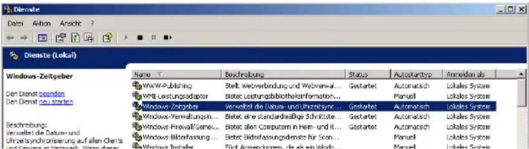
Figure 21: MS-Timeservices
To turn your Windows computer into a timeserver, double-click on the clock in the lower right taskbar and open the following example. After some seconds the tab "Internet Time" appears.
Click on "Internet Time" and check if the timeserver you have chosen here works correctly.

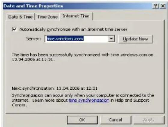
After having configured and started your Microsoft Windows Timeserver you have to reboot your computer and check the Event Logfile of Windows to ensure, the service was started correctly. In this case, you can configure your CS121 Timeserver using the IP-address of this Windows computer.

Note: Please check if your computer is reachable through the network. You may have to change the Windows Firewall settings.
3.2.5 Events / Alarms
The Event/Alarm-pages are the main feature of the CS121-configuration and are based on a combination of events and actions (resp. Jobs). At CS121 there are various events defined, such as e.g. "Powerfail", "UPS Battery bad", "Battery low" etc. Each event the CS121-adapter allows you to release one or more actions. An action can be e.g. to write a logfile-entry in the alarm-logfile (as default all events do perform an logfile-event), to send an eMail or to perform an RCCMD-Command (e.g. shutdown signals to several RCCMD Clients). For a short introduction into the handling of Events and Actions see also the section "Quickstart".
In this menu the relationships between system events such as alarms and the actions to be taken those events are defined.
To configure your events and actions open the menu "Events / Alarms". The menu "Event Configuration" shows you an overview about the events and the number of configured actions.
Event Configuration

Figure 22: HTTP - Event Configuration with tool tip
▶ Choose the event you wish to configure to enter the event editor.

Figure 23: HTTP - Event Editor
The Event Editor allows you to edit, delete and test existing events, as well as to add a new event job. Please click on the desired action to enter the Job Editor, who lets you make the configuration.
Here in the following a short example how to configure an RCCMD-Shutdown signal. For further explanations please see section 3.2.5.4 RCCMD Jobs later on in this manual.
- Generally, the event "Powerfail" (in same environments also named "Backup mode") should be used to enter the RCCMD-Shutdown commands, where required with a delay ("do after") or depending on the remaining time.
| Event Jobs for 'Powerfail' | ||||||||
| Job Type | When | Parameter 1 | Parameter 2 | Parameter 3 | ||||
| 1 | Edit | Del | Test | Log | P100 | Powerfall | ||
| 2 | Edit | Del | Test | RCCMD Msg | O | 192.168.202.51 | 6003 | Attrnition: Powerfail occured!!! |
| 3 | Edit | Del | Test | RCCMD SD | P12 | 192.168.123.123 | 6003 | |
Figure 24: HTTP – Event Editor, Example of a Shutdown-Configuration
- Additionally, all Actions of the Event "Powerfail" should also be entered in the Event "Battery low" without any delay.
- The Event Editor offers you 3 commands on each Job: Edit, Delete and Test. (See figure above) Please note: the Test will perform the execution actually, which means for example, that testing a RCCMD-Shutdown Job will actually release the Shutdown-Signal at the Client-side! You should perform a Shutdown-test not until you have switched off the Shutdown-procedure at the Client. (RCCMD Configuration, Button Configure shutdown)
- All Jobs are saved not until you executed the Save, Exit and Reboot-Procedure, not until the device is restarted and running in normal mode (DIP-Switch 1 is ON).
- The number of jobs per event is limited. CS121 Series 2001-2006 allow up to 25 jobs, running under Firmware 3.5x even up to 35 jobs (approximatley, depends on the jobs). If more jobs should be executed, you have to configure RCCMD as relay-station, as described in section 5.1.2.
3.2.5.1 Treshold events
Some UPS models allow you to configure thresholds for releasing UPS specific threshold events individually. CS121 also supports these features if the UPS includes this option. In this case, you see at the main Event menu "Event configuration" at the bottom an additional link "Configure threshold events". Click here to add a new individual threshold event and you enter the configuration page "Threshold Events", within you get the possibilities to configure individual events.
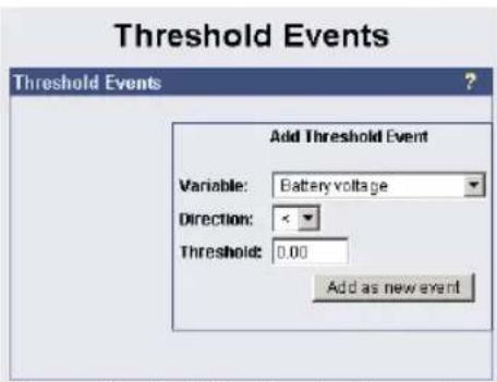
Figure 25: HTTP – Treshold event
3.2.5.2 Logfile entries
For a numerous of events logfile-entries are already pre-configured as default. To configure a new logfile-entry, type in the field "Text" the desired message you wish to enter in the logfile and choose the option on the right side, when/how often the message should appear in the logfile.

Figure 26: HTTP - Job Editor: Logfile-entry
Example above: The text "Powerfail" will written into the logfile every 100 seconds for as long as the event is present. Other actions on events such as Email, RCCMD-shutdown, UPS-Dialer, TempMan etc. can be configured in the same way. Each event may have an unlimited number of actions (executed now, delayed etc.).

Note: Do not forget to apply your changes before leaving the menu to send the values to the CS121-adapter!
The CS121-logfile is located in the adapter root directory “../flash” The user can read the Alarmlog-file using a FTP connection with the default IP address 10.10.10.10 or the configured IP-address and the username/password combination “admin/cs121-snmp”. Alternatively the logfiles can also be watched with the GENEREX monitor-tools UPSMON or JAVAMON resp. via the Webbrowser. About the logfiles-contents please see also section 3.3 Reading the Alarm-Logfile.
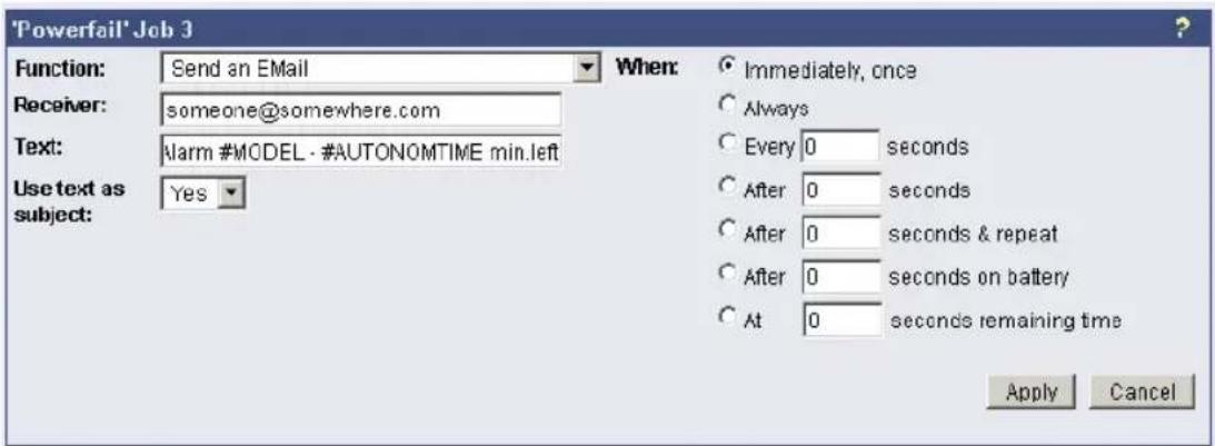
Figure 27: HTTP - Job Editor: Email-Job
To configure an Email-job follow the entries in the figure above.

Note: Please ensure that your Email settings in the menu "Email" are valid. (See also section "Email" above)
Besides text entries, variables can also be integrated into the email from the CS121-adapter. This may personalize your emails. A list of available variables are documented in the appendix (Section E Available Variables of the CS121). Please mind, that the variables are only getting filled if the event actually occurs, not by testing the action. (So simulation is not possible, you have to create a real alarm to see the full message)
For example please see the figure above: There, the variables #MODEL and #AUTONOMTIME will be substituted with their current values when the action will be released. Please notice the syntax, that each variable name must be started with the character # and must be ended with a
- Apply your settings and test the Email-job in the "Event Editor" to ensure Email will be sent.
• Continuous, periodic events:
To define an event job which will be executed continuous, e.g. daily, create a job on the event „UPSMAN started“, as in the following figure:
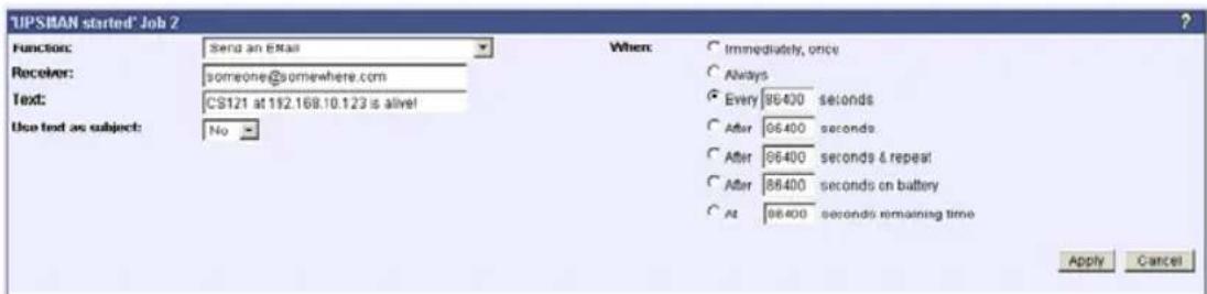
Figure 28: HTTP - Job Editor: Continuous event job
3.2.5.4 RCCMD Jobs
RCCMD (Remote Console Command) is the world's most successful shutdown client for heterogeneous networks and is the most secure way to establish a UPS multiple server shutdown sequence today. RCCMD clients are listening to an RCCMD server which is usually an UPSMAN software, CS121 or any third-party UPS manager which has a license to use RCCMD. An RCCMD server is found inside any CS121 and is triggering RCCMD clients in case of alarms. Therefore RCCMD requires such listeners on each client-computer you wish to forward RCCMD signals. For installation of RCCMD at client-side please see the section in chapter "Add-on software".

Note: RCCMD clients are optional and not freeware. Most CS121 are equipped today with a single RCCMD standard license, some UPS makers add more licenses, other do not deliver any license at all with a CS121. Contact your UPS maker and ask for the license regulations for RCCMD in conjunction with your CS121.
- Certain pre-settings are imperative for all RCCMD actions.
- First of all in general regards to the CS121-adapter as an UPSMON Server, the „Enable UpsMon Server“ and the „Use RCCMD2 Traps“ controls boxes must be checked in menu “Network & Security Settings”. (default is ON) This enables the CS121 to execute its RCCMD actions.
- Secondly, the CS121 adapter and the RCCMD client must both be appropriately configured in order to reach one another using RCCMD commands over the network.
- Because the CS121 adapter plays an active roll when executing its actions “Message”, “Shutdown” and “Command” (that is to say the CS121 -adapter sends an RCCMD-signal to an RCCMD client), it is necessary, to enter the IP-address in parameter 1, and the port number of the RCCMD client in parameter 2 (default port is 6003). Additionally, the RCCMD client must either be pre-configured with absolutely no sender filter or should be pre-configured with the IP-addresses of the particular UPSMAN servers (like UPSMAN, CS121 or other RCCMD compatible sender) that are to function as recognized senders. These configurations take place when installing the RCCMD client service. Further details are in the RCCMD software documentation.
- RCCMD also includes the feature “RCCMD Trap”. RCCMD Trap is a method for sending information to the RCCMD stations which have been applied to the CS121. RCCMD Traps invokes messages at all RCCMD stations. Because of RCCMD plays an active roll in this mode no receiver information is to be entered in the parameters of this job (see also following sections). It is condition to enable the RCCMD Trap control box in the menu “Network & Security Settings”.
- The CS121-adapter uses the parameter-based RCCMD Version 2, which can execute different actions on the same TCP channel. RCCMD Version 1 clients can only execute one action (shutdown file execution as default, so any RCCMD signal which is transmitted to an RCCMD client V1 will cause a shutdown of this server) RCCMD Version 3 is capable to handle also redundant UPS installations (eg. PC with 2 power supplies and 2 UPS).

Note: For all 3 RCCMD event functions a list of the user configured RCCMD receivers appear in every RCCMD event.
- The maximum number of RCCMD clients is unlimited. However it is only possible to execute 50 clients at the same time, meaning that the first 50 RCCMD clients are executed followed by the next 50 etc. We recommend to change the timing parameters of the RCCMD-jobs that always less than 50 commands are transmitted at the same time. We also recommend to use an RCCMD client as Relaystation if you want to shutdown more than 50 computers from a single CS121. (see section 5.1.2 RCCMD client as relay station)

Note: The RCCMD timeout is 60 seconds, meaning that after this time the communication to the RCCMD client will be stopped and a logfile entry will be made. When an OK response from the client is received, the system assumes a successful RCCMD Shutdown and proceeds with a shutdown of the next 50 RCCMD clients. Every minute one batch of up to 50 RCCMD clients can be executed.
License regulations:
Please note that in order to use these functions legally, the corresponding RCCMD client program is installed and started from the UPS-Management Software CD. The RCCMD license code can only be used once per installation. If more computers need to be added to the shutdown process, additional RCCMD client licenses are required.

Note: All network components, such as routers, hubs etc. need to be fully UPS-supported, as it is otherwise not possible to reach all clients during the network shutdown.
3.2.5.4.1
RCCMD
Shutdown
Job Editor
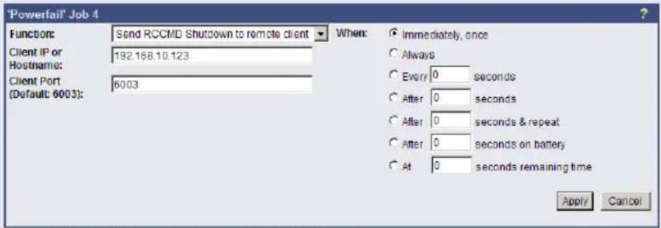
Figure 29: HTTP - Job Editor: RCCMD Shutdown
Here, IP-addresses from computers with RCCMD connection (receivers) in the network can be entered. The CS121-adapter can then initiate a multi-server shutdown. The timing for such a shut down procedure depends on the configured down time of the adapter (default: time of the remaining capacity of battery in min., during a long power fail.) or on a count down timer. Extended CS121-adapters can also use more events (e.g. battery low, battery defect, communication lost etc.) as RCCMD signals. Please contact your UPS dealer for more information.

Note: For security reasons we recommend to make the same RCCMD shutdown entries for the Event "Battery low" - but in this Event without any delays to avoid that the server crashes because of low battery alarm.
In case a connection is established using telnet or http, the RCCMD-command can be tested without using disrupting power to the UPS. At the Webbrowser you simply have to press "test" to transmit the shutdown signal immediately. (see figure HTTP - Event Editor above)
Due to network settings it is possible that this test is answered with "failed". The signal is often sent and received although the receiver may not respond correctly. In such cases, only use the receiver side to check if the signal has actually been received. For checking the communication between RCCMDs you have to check the RCCMDlogfile on both sides. In the CS121 the logs are inside the Alarmlog, at the RCCMD client side the logs are found inside the RCCMD folder eg. Rccmd.log.
3.2.5.4.2
RCCMD
Message
With this job the user can combine and configure a text message with RCCMD event. Text messages can be sent to RCCMD receivers. This makes it possible to send text messages via RCCMD (version 2 or higher) to a Windows 2000 server or a Unix computer, using the "NET SEND" or the respective "WALL" method. The problem with notifying network users on different operating systems is therefore solved.

Note: The corresponding RCCMD clients must be running with RCCMD version 2. RCCMD version 1 can only execute e.g. a shutdown as more than one action are not supported by version 1. Please contact your UPS dealer if you want to use these functions.
3.2.5.4.3
RCCMD
Execute/command
This RCCMD signal will cause any RCCMD receiver (e.g. another CS121, RCCMD client or SITEMANAGER, SITESWITCH4) to execute a command or program.

Figure 30: HTTP - Job Editor: RCCMD execute/command
Any CS121, SITEMANAGER, SITESWITCH can also act as an RCCMD listener; see the following examples:
3.2.5.4.4 Example of use 1: CS121-adapter as RCCMD-listener
If it is necessary to execute a command with parameters or a user defined script then these commands must be prepared as an executable batch on the RCCMD client.
The following example toggles the state of AUX output port 2 to high. To ensure that the above command works with a CS121 as RCCMD client the following four criteria must be met:
- Enable RCCMD Listener and set RCCMD Listener Port in menu "Network & Security".
- Add IP of UPSMAN sender in the SNMP community of the CS121-RCCMD client (see also section "SNMP")
- Target AUX port must be set to "use as Output" (menu AUX, see according section)
- The send RCCMD Command must match the settings of the CS121 RCCMD listener client.
See the UPSMAN User Manual for setting up this job on a computer running UPS Management Software.
3.2.5.4.5 Example of use 2: CS121-adapter switches an output
CS121 receives an extern RCCMD signal to switch an output at the SS4 (Power switch) which is connected to the AUX of a CS121.
If you want to send from a CS121, UPSMAN, SITEMANAGER, SITEMONITOR, SITESWITCH 4 or any other RCCMD sender a signal to any other RCCMD client e.g. to switch at its AUX port an output, please follow the example below.

Note: To let the receiver act as RCCMD listener, same basic settings in menu
"Network & Security" are necessary: Please ensure that the option "RCCMD Listener" is enabled and the RCCMD Listener port is specified. (Usually the listener port is 6002)
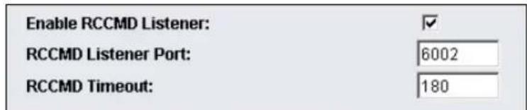
Figure 31: HTTP – Enable RCCMD Listener
Generally there are 3 commands which can be transmitted from any RCCMD Sender:
Switch Output (AUX): Syntax „|UPSCMD|20000|x,y“
where "x" is the port number from 1-8 (4 ports for CS121 AUX, SENSORMANAGER and SITESWITCH and there are 8 ports for the SITEMANAGER)
y=1 => switch on
y=0 => switch off
"20000" is the command to switch outputs. (for other commands please contact GENEREX support)
Syntax examples:
| UPSCMD | 20000 | 1, 1 = Output 1 on
| UPSCMD | 20000 | 1, 0 = Output 1 off
| UPSCMD | 20000 | 2, 1 = Output 2 on
| UPSCMD | 20000 | 8, 0 = Output 8 off
Job Editor
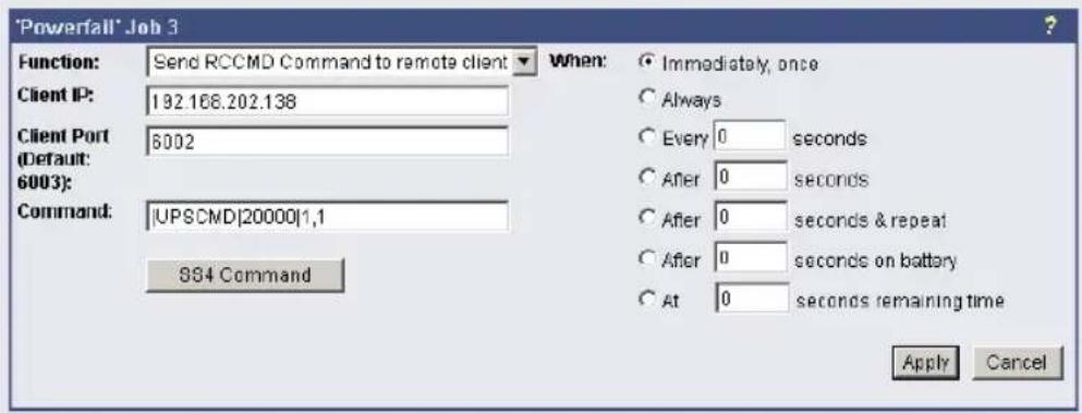
Figure 32: HTTP - Job Editor: RCCMD-Command
- Confirm a digital alarm: You can also use this syntax to e.g. confirm alarms for digital inputs (e.g. Fire-alarm, door open, air-condition failed, etc.) which you see in the UNMS software as "New Alarm". E.g. if your UNMS software shows an active alarm and you want to "acknowledge" this alarm by a switch witch you connected to a CS121 or SITEMANAGER, than you can use the following syntax to program your device to send an "ACK" signal to the receiver. After this your UNMS will show "Alarm acknowledged – recovery action in progress".
Syntax : |UPSCMD|20001|x
where x is the Portnr. (1-8). („20001“ is the ACK command for digital signals)
Syntax example: |UPSCMD|20001|2
This command confirms the Digital-Alarm 2 on a SITEMANAGER, SITEMONITOR, SITESWITCH or CS121 AUX Inputs.
- Confirm Analog-Alarm : The way it works with the ACK of analog alarms like Temperature thresholds exceed on the UNMS.
Syntax : |UPSCMD|20002|x
where x is the Portnr. (1-8). ("20002" is the ACK command for for analog signals)
Syntax example: |UPSCMD|20001|4
This command confirms the Analog-Alarm 4 on a SITEMANAGER, SITEMONITOR, SITESWITCH or CS121 AUX Inputs.
3.2.5.4.6
RCCMD
Trap
RCCMD Trap is the automatic messaging system of CS121, working with RCCMD clients. If jobs have been configured in this category, the actions that are set here will be executed only when an RCCMD client has established a connection to the UPSMON server of the CS121.
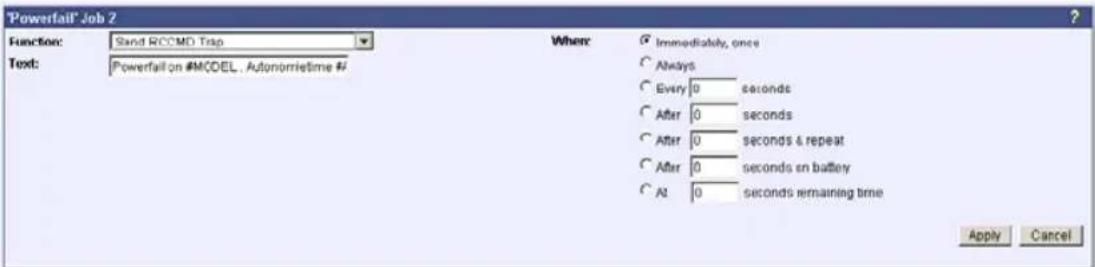
Figure 33: HTTP - Job Editor: RCCMD-Trap
3.2.5.5 UPS shutdown
This event action enables an UPS shutdown. It is possible to configure when to send a shutdown signal to the UPS in case of an e.g. battery low, firealarm or if a complete power down is wanted. Attention: This command will cut off the power supply – only for UPS which support this function!
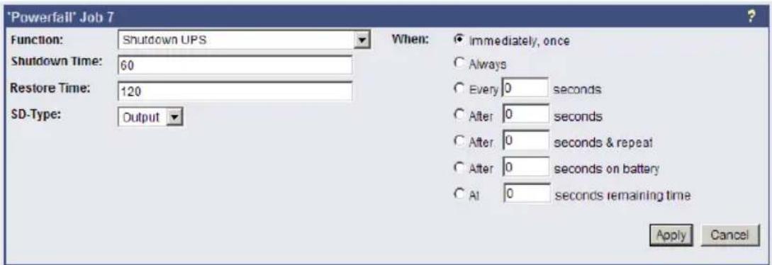
Figure 34: HTTP - Job Editor: Shutdown UPS-Job
The example above configures that 60 seconds after the event powerfail has occurred, the UPS is initiating a shutdown and the UPS waits another 120 seconds after the event powerfail is gone (power restored), before the UPS start up is initiated.
3.2.5.6 AUX-Port
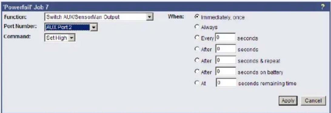
Figure 35: HTTP - Job Editor: Switch AUX-Port
In general, the AUX port is used for auxiliary contacts that can be configured to function as either an Input or an Output. (e.g. as input for Air-conditioning alarm contacts and as Output to switch on electrical sockets or start Beepers etc.) When these contacts are set as Inputs, they are to be treated as an event in the „Events settings“-menu. Reverse, the AUX contacts to be treated as actions when they are being used as Outputs. The AUX port is also used for connecting an SS4/AUX power outlet manager, in which case all AUX ports function as Outputs. For the AUX we provide several “add-ons” like the SS4AUX, SM_IO Relaybox, SM_BUZZ Alarmbeeper, etc. For a complete overview of “add-ons” for the AUX please see the according datasheet, downloadable from www.generex.de.
3.2.5.7 Wake on LAN (WOL)
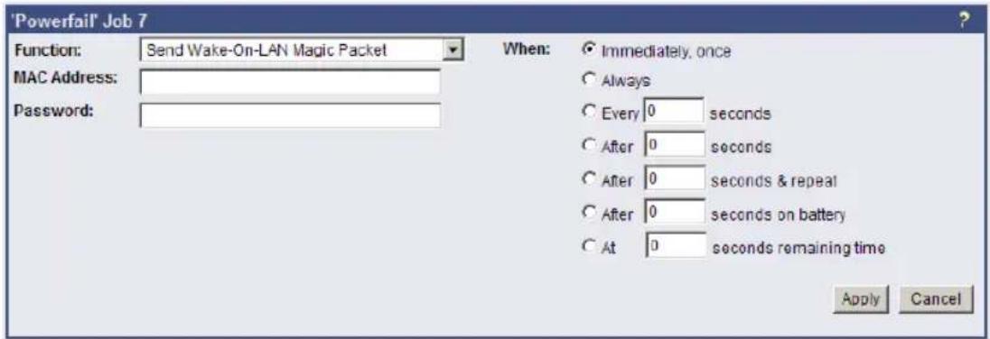
Figure 36: HTTP - Job Editor: Wake on LAN
WOL stands for "Wake on LAN". This function uses data packages to prompt other computers in a local network to start-up. Please use this function in the event "UPSMAN started" to wake up computers which have been shutdowned previously after an extended poweroutage, which cause the CS121 or UPS to switch off completely. Additional you may add this WOL signal to the EVENT "Power restored".

Note: Not all network cards support this function, and for those network cards that do, some of them are password protected. Please enable this function on your computers BIOS settings on the motherboard.
3.2.6 Scheduled Actions
This menu is for programming schedules actions on your CS121 or facility manager SITEMANAGER. When combined with the other facility managing functions of the CS121 adapter, the Scheduled actions tool can be used to operate and run many different tasks, e.g. Switch on/off UPS, do battery tests, switch to "greenmode" or bypass, etc.
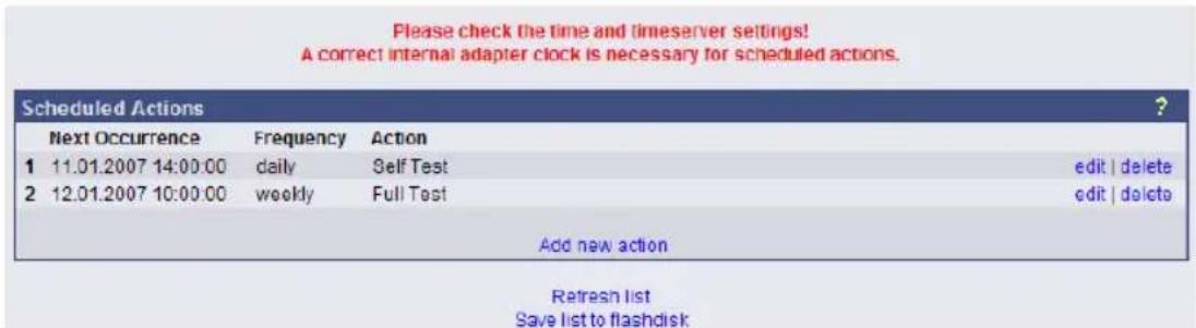
Figure 37: HTTP - Scheduled Actions with warning
After pressing the "new"-button a configuration window will be opened for the making of new entries into the scheduled events of the adapter. This is a very dynamic and versatile configuration window that automatically readjusts itself to adapt to the selected job. Just select a different type of Action and see how the configuration window changes. This makes it very easy for the user to configure the individual jobs. In addition, the window makes the scheduling of reoccurring events very easy by offering the selection of ONCE, DAILY, WEEKLY, and MONTHLY for each new entry.

Note: Please ensure that timeserver settings are valid when you configure scheduled actions. An unreachable timeservice will be indicated at the top of the menu "Scheduled Actions".
3.2.7 SNMP
Within this menu you can define access controls for SNMP-communities. This concern e.g. SNMP-Management tools, Trap receivers etc.
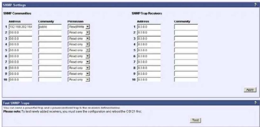
Figure 38: HTTP - SNMP
• Network Server Settings
The user may activate or deactivate different options from this menu. Telnet and or SNMP may be switched on or off and the UPSMON access can be blocked. The network speed can also be selected and the user can select and adjust the desired security level.

Note: Please ensure that in the menu "Network & Security" the option "SNMP Agent" is enabled. SNMP Traps have nothing to do with RCCMD traps or the RCCMD shutdown functions. RCCMD works independent from SNMP.
The submenu displays a column of 10 manager IP-addresses with the corresponding access permission, the commands and an example. Use this screen to specify which managers have access to the SNMP adapter agent, the community names (password) and also what type of access the IP managers have - read only or read and write.
- Configuring Trap-receivers
Use this to determine which IP managers receive traps (messages) from your SNMP-adapter. The screen permits you to send traps about your UPS to IP-addresses (managers).
Also, the menu for switching authentication and cold boot traps are located here. If activated these traps are send to the configured SNMP trap receivers in the trap receiver list.
- SNMP Trap Test
In this menu the user may test the SNMP traps, whereas the defined traps are only used for test purposes and do not represent real traps. The receiver must also be configured in order to make this test work. Additionally, save the settings and reboot your CS121 before testing the communication with the configured IP-address. (does not work in configuration mode)
See also Network & Security-Settings
3.2.8
COM2
&
AUX
3.2.8.1
COM2
This menu takes the user into the submenus for the general settings of the COM2 and AUX connection ports of the CS121-adapter.
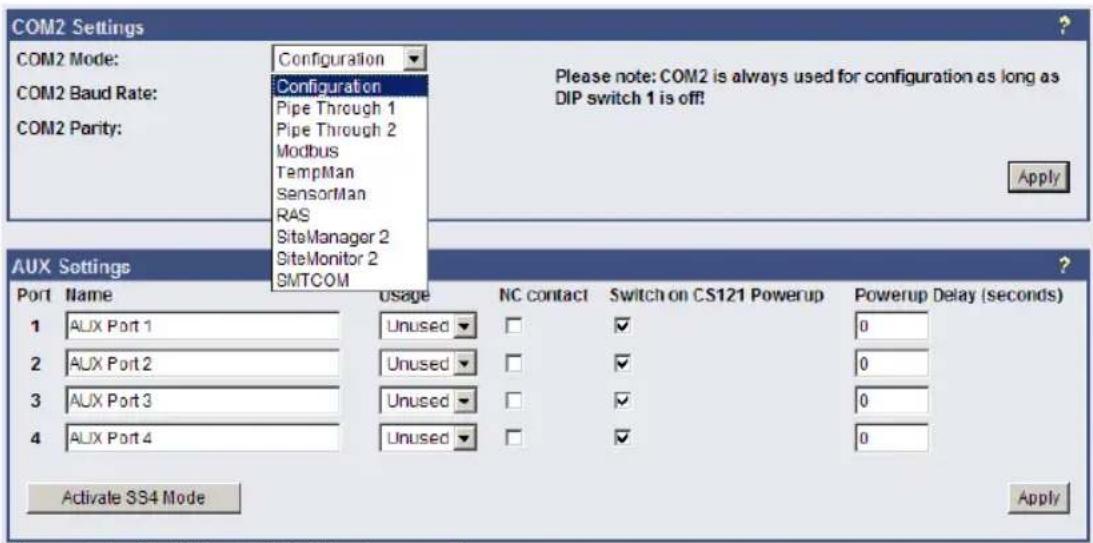
Figure 39: HTTP - COM2 Mode overview
- Configuration Mode:
This sets the normal configuration mode for using the provided cable (CS121-TEMP configuration cable).

Note: Unless DIP-switch 1 is OFF the COM2 port is always running in configuration mode.
- Pipe-Through Mode 1:
Enable or disable the "pipe-through" of the adapter. If enabled, the RS-232 protocol of the UPS will be transmitted to the COM2 of the adapter, so now you can connect any other RS-232 software to the adapter to make use of the RS-232 UPS protocol – parallel to the adapter. This makes the use of multiplexer hardware is no longer necessary. 2 serial interfaces on your UPS which are working parallel are utilized now. Reminder: If you have enabled this function, you can no longer configure the adapter via the serial cable, you must changed the settings via HTTP. As communication cable between CS121 and your application you have to use the original CS121 configuration cable.
- Pipe-Through Mode 2:
Analog to Pipe-through mode 1, the UPS data is piped through to COM2 but not directly. In order to accelerate the internal processes of the adapter, the UPS data is accumulated into memory before being made available to COM2. Consequently, Pipe-through mode 2 also does not provide for the relaying of signals to the UPS through COM2 either. (See also section "Network & Security Settings")
• TEMPMAN & SENSORMANAGER:
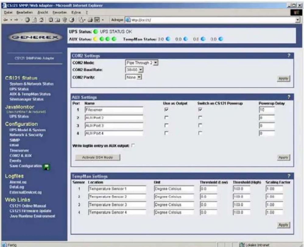
Figure 40: HTTP - COM2 & AUX with TEMPMAN
The TEMPMAN and SENSORMANAGER are extensions to the CS121 that connect to COM2 of the adapter. The newer of the two products is the SensorManager. These devices are simply plugged into the CS121 for setup and the only mandatory change on the adapter to enable this functioning is to set the COM2 Settings to either TEMPMAN or SENSORMAN. The configuration is easily achieved via the HTML page of the CS121 web server. Please note the drop-down menu and entry fields on the page. (see screenshot above) For in-depth SENSORMANAGER settings see following up chapter.
- RAS-Mode
The selection of the "RAS"-entry in the drop down menu of the COM2 settings enables the CS121-RASManager function. This function is only operational if a RASMANAGER is used (CS121 with inbuilt modem) and a RASMANAGER license key is provided (optional, part of RASMANAGER). While it is also possible to select this entry in the Telnet menu, it is only possible to configure the RASMANAGER settings using the HTTP interface of the CS121. See menu "RAS Configuration" for further settings.
3.2.8.2 AUX and SITESWITCH4 Settings
The AUX connection is an input/output port for connecting external contact devices such as alarms or for connecting to an SS4AUX SiteSwitch power socket manager. The SS4 SiteSwitch is a standalone device with a built in CS121. The SiteSwitch SS4 AUX is an inexpensive and practical extension to the CS121 adapters enabling the individual power switching of up to four power sockets – using the inbuilt AUX port (4 pins) of the CS121. By entering the corresponding list number, the AUX ports are switched to output or input.
The AUX port can only read signals, if the port is switched to input. If switched to output the AUX port can send signals to an optocoupler for example. (Refer to the circuit diagrams in the appendix.) After a reboot, the state of the switches remains in the status previous to the reboot.
The following describes the configuration of the AUX ports using the HTML interface. All of the AUX ports 1 – 4 can be manually set to „Output“ so that in the event of an alarm, the CS121 can be preconfigured in the “Events” menu to switch the ports individually. When all ports are
set to "Output", this is equivalent to activating the „SS4 Mode“. The SS4 mode is to be activated when connecting a SITESWITCH4 to the AUX port of the CS121.
When the Output options are deactivated, the AUX ports act as inputs used for monitoring signals such as input from alarm contacts. For example, while configuring port 2 as an input to monitor an alarm, the CS121 can also be preconfigured to respond to the alarm signal from port 2 to shut on or off a device connected to one of the other ports that has been set to Output.
For example see also the settings in figure "HTTP - COM2 & AUX" above.
The OUTPUT setting is to be configured with a power-up sequence so that, for example the fileserver on port 1 will be switched on upon Power up. In the Power up delay-fields the number of seconds after a Power up in which a connected port device is to be switched on can be entered. E.g. the setting 10 in the Power delay column will cause the switching on of the fileserver on Port 1 to be delayed by 10 seconds after the Power up. Note that executing the Save, Exit & Reboot does not cause a Power up, in order to cause a Power up the power supply to the adapter must be interrupted. The differences between a Reboot and a Power up become more noticeable when considering the AUX port contacts. During a Reboot the current status of the ports remain unchanged unless the settings of the ports have been changed from input to output or vice versa. A Power up will set the ports to the preconfigured Power up settings.
3.2.9 SENSORMANAGER
The SENSORMANAGER is a data measurement and collecting unit which allows the individual measurement and monitoring of 8 analog measurement devices (0-10V) and 4 digital alarm inputs or 4 outputs (open collectors). SENSORMANAGER has its own chapter in the manual, wherein the features and field of applications etc. pp. are described as well as in depth the various specific configurations.
In generally, the SENSORMANAGER unit is connected with its COM 1 port to CS121's COM 2 port, which has to be configured as SensorManager mode (see also section COM 2 settings above).
Within the configuration page “Sensor Manager Settings” of the CS121 you can - among others - define limit values when events (to be configured in “Events / Alarms”) will be released.
| Sensor Manager Settings | ||||||||
| Sensor | Location | Unit | Current Value | Threshold (Low) | Threshold (High) | Sensor Type | Scaling Divisor | Scaling Offset |
| 1 | Temp. Sensor 1 | Degree Celsius | 0.0 | 0.0 | 100.0 | Custom | 2.55 | 0 |
| 2 | Temp. Sensor 2 | Degree Celsius | 0.0 | 0.0 | 100.0 | Custom | 2.55 | 0 |
| 3 | Temp. Sensor 3 | Degree Celsius | 0.0 | 0.0 | 100.0 | Custom | 2.56 | 0 |
| 4 | Temp. Sensor 4 | Degree Celsius | 0.0 | 0.0 | 100.0 | Custom | 2.55 | 0 |
| 5 | Temp. Sensor 5 | Degree Celsius | 0.0 | 0.0 | 100.0 | Custom | 2.55 | 0 |
| 6 | Temp. Sensor 6 | Degree Celsius | 0.0 | 0.0 | 100.0 | Custom | 2.56 | 0 |
| 7 | Temp. Sensor 7 | Degree Celsius | 0.0 | 0.0 | 100.0 | Custom | 2.55 | 0 |
| 8 | Temp. Sensor 8 | Degree Celsius | 0.0 | 0.0 | 100.0 | Custom | 2.55 | 0 |


Figure 41: HTTP – Sensor Manager Settings
Please see SensorMan in section "Accessories" of this manual.
3.2.10 RAS Configuration
This is the standard setting for the RASManager, the CS121 with the built-in modem. Most of the CS121 products can also have the RASManager feature enabled by purchasing PPP License Key and by connecting a supported modem. The RASManager and RASControl software come with an extra user manual for describing this feature.

Figure 42: HTTP - RAS Manager Settings
3.2.11 Save Configuration / Reboot
If you are satisfied with your configuration select "Save, Exit & Reboot" and wait until the adapter informs you about the reboot-process.
Please notice that a reboot of the CS121 may take up to 3 minutes. During the boot phase the CS121 is compiling the user settings and waits for timeserver response. As soon as the start-up process is through and all requested data are present or „timed-out“, the UPS communication starts and the green LED is flashing to signalize the UPS RS-232 traffic. Now the device is ready for use and you may check the UPS values with any Web browser (http://
3.3 Reading the Alarm-Logfile
The CS121-Alarmlog contains the alarm protocol of events that were designated as alarms in the Event/Settings-section and include the user defined alarm settings of the CS121 configuration as well as the events that are designated as alarms in the UPS native protocol. These entries include such things as CS121 Admin defined email notifications which lead to a much higher alarm entry log level than would otherwise be the case if only UPS protocol defined alarms were being recorded. For explanation, the following illustrates typical log file entries made by the UPS:
The CS121 logs the time after a new start up:
01/17/2007,16:21:45, Synchronized with timeserver 192.53.103.103. OK
This indicates a successful synchronization with the timeserver.
01/17/2007, 16:23:39, UPSMAN
UPS communication functions and device is in normal operation mode. This is the standard entry after every successful reboot of a CS121.
(The following entries result only from user defined settings as with the CS121 ADMINISTRATOR EMAIL Settings.)
01/17/2007, 16:28:39, MAIL: subject "CS121 Event 4" successfully sent.
All "EVENT X" designated alarms are viewable in the EVENT list of the web browser. EVENT 4 for this particular UPS is the EVENT "UPSMAN started" – This means that an Email was sent with the text "UPSMAN started" which acts to confirm the log entry of 08:06:50 as Email.
01/17/2007, 16:28:47, MAIL: subject "CS121 Event 16" successfully sent
In this case, the Scheduler has been activated and is ready for operations. In this case, the scheduler is set to conduct a "Selftest" which it in turn relays per email to the designated CS121 ADMIN.
| 01/17/2007,16:28:47,MAIL: | subject "CS121 Event 26" successfully sent |
| 01/17/2007,16:29:03,MAIL: | subject "CS121 Event 27" successfully sent |
| 01/17/2007,16:29:28,MAIL: | subject "CS121 Event 28" successfully sent |
| 01/17/2007,16:30:46,MAIL: | subject "CS121 Event 29" successfully sent |
These are 4 Emails indicating the status of the AUX Ports (Auxiliary connection for external alarms), which are set to give notification of the status signal LOW. Since the AUX Status can only be set to High or Low and given that the CS121 in itself cannot distinguish the device, an alarm email will be sent by the CS121 to the designated ADMIN at startup per default with the startup status of each connected alarm. In this case, it is up to the administrator to determine if the emails indicate an actual alarm or not.
| 01/17/2007,16:34:48,MAIL: | subject "CS121 Event 38" successfully sent |
| 01/17/2007,16:35:12,MAIL: | subject "CS121 Event 39" successfully sent |
| 01/17/2007,16:35:16,MAIL: | subject "CS121 Event 40" successfully sent |
| 01/17/2007,16:35:28,MAIL: | subject "CS121 Event 41" successfully sent |
| 01/17/2007,16:35:33,MAIL: | subject "CS121 Event 42" successfully sent |
| 01/17/2007,16:35:40,MAIL: | subject "CS121 Event 43" successfully sent |
01/17/2007, 16:35:51, MAIL: subject "CS121 Event 44" successfully sent 01/17/2007, 16:35:57, MAIL: subject "CS121 Event 45" successfully sent
These are 8 Emails sending information about analogue sensors (temperature, humidity and the like) that are connected to a SENSORMANAGER, indicating that all controlled values are within tolerance levels - or that no sensor is connected to the device or connection port.
01/17/2007, 16:36:30, MAIL: subject "CS121 Event 54" successfully sent 01/17/2007, 16:36:41, MAIL: subject "CS121 Event 55" successfully sent 01/17/2007, 16:36:48, MAIL: subject "CS121 Event 56" successfully sent 01/17/2007, 16:36:57, MAIL: subject "CS121 Event 57" successfully sent
These 4 Emails indicate that the digital sensors (for airconditioning, fire alarms and the like) of the SENSORMANAGER, are either in the normal state or that no sensor is connected.
01/17/2007, 17:41:12, MAIL: subject "CS121 Event 62" successfully sent 01/17/2007, 17:41:36, MAIL: subject "CS121 Event 63" successfully sent 01/17/2007, 17:43:23, MAIL: subject "CS121 Event 64" successfully sent 01/17/2007, 17:44:01, MAIL: subject "CS121 Event 65" successfully sent
These 4 Emails indicate the status of the digital alarm contacts of the sensors (for Emergency OFF, fire extinguisher and the like) connected with the SENSORMANAGER, showing either the status is NORMAL or that nothing is connected.
01/17/2007,17:52:13,MAIL: subject "CS121 Event 70" successfully sent
This Email shows that no SENSORMANAGER is connected although the CS121 is configured as having a connection to a Sensormanager. This informs the ADMIN that the CS121 is incorrectly configured. In this case, the user should correct the settings.
4. Adapter Software-Updates (Firmware)
Usually the CS121-Adapter already contains a specified firmware-version and does not need to be updated unless you have problems or you find a update recommendation on our website. (use firmware online update link on CS121 page).
If you have connected your CS121 via LAN a link at the Webbrowser configuration page (CS121 Firmware Update) indicates you with red or green coloured information whether you should perform a Firmware-Update or not.
Firmware Update Page
Device: CS121
OEM Id: 4
Your version: 3.51
Latest version: 3.51
No newer firmware available. Update is not possible.
Complete Version History
Figure 43: HTTP - Firmware Update Page

Note: We strongly recommend to update any firmware lower than 2.69 to the actual version!
All actual Firmware-updates are provided at www.generex.de download page.

Note: Any interruption of a firmware upload may damage your adapter. If this is the case, you have to reformat the adapter with special software See section "Firmware Recovery". or contact your UPS software support for more information.
The boot procedure of the CS121-adapter performs several steps:
- First, the firmware is going to be uncompressed.
- Starting firmware
- Control process called UPSMAN is going to be started and USV connection is trying to established
• Services e.g. Webserver etc. started
There are two ways to update your firmware-version, by using the Setup-tool or via FTP.
4.1 Firmwareupdate via Setup-tool
Firmware updates are available for free at www.generex.de. Download the specified version (mind your OEM ID) and follow up the setup-procedure. If necessary, consult your UPS dealer for further information.
4.2 Firmwareupdate via FTP
A firmware update can be made via FTP during normal operation of the CS121-Adapter (username: "admin", password: "cs121-snmp"). Simply overwrite the older firmware files, PROJECT.HEX, UPSTYP.UPS and MESSAGES.DAT in the FILES folder with the newer files and reboot the adapter. Afterwards, reconfigure the device via Telnet. For more details read the README.TXT of the firmware update package.

Note: The configuration of the CS121 can be saved for archiving purposes using an ftp-connection. Simply download the „upsman.cfg“ to the directory of your choice. Later on, after the CS121 has been updated,
the configuration can be saved back into the „flash“ directory of the CS121 per ftp.
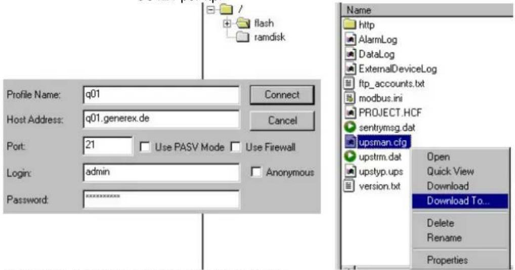
Figure 44: CS121-configuration settings via ftp.
A firmware-update via FTP changes not only the operating system part of the CS121, if you want to change also UPS manufacturers data you have to overwrite also the file UPSTYP.UPS. Please contact your UPS software support for further information.
4.3 Firmware flash renewal and recovery

Caution: This upgrade process requires some technical knowledge. This process can seriously damage your CS121 if not performed correctly. Please follow the instructions carefully to avoid damaging your system! We strongly recommend to use the CS121 update tool to avoid conflicts and to safely update your CS121.
General information regarding the upgrading process of the CS121 - Known Problems and Preliminary Precautions:
- Any update will cause a deletion of all former settings. The adapter must be reconfigured after the update. The current settings information can be saved by using an FTP connection to your adapter to save the upsman.cfg file in the flash directory to a local directory. This file contains all of the information about the current CS121 settings in a formatted text. Do not copy this file back onto the adapter after the update as a replacement for the new upsman.cfg. The information must be entered back into the settings using the adapters configuration interface. Note that the http interface often contains newer settings options that are not yet implemented in the telnet and terminal interfaces.
- Any recovery should be made on the default IP Address 10.10.10.10. Put DIP Switch 1 and 2 in the OFF position before starting.
- Please avoid the use of routers and switches between your computer and the CS121, if available use Hub (recommended) or a direct line (Ethernet-cross-cable).
Instructions for recovery procedure:
In case the CS121 is not running, has any defect or other problem, please put dip switch 1 to OFF (Dip 2 should be always OFF) and follow the procedure below:
- Before starting the update, unplug the adapter from the power supply (slot cards have to be removed from the slot).
-
Set a route to default IP-Address. Command syntax on your windows computer: "route add 10.10.10.10 <your IP address)". Also note that the flash tool can also be used to set the route for you by checking the set route check box in the update interface.
-
Check if your route is correctly set with the console command "route print". You should see that 10.10.10.10 is in the list.
- Make sure that no other device is answering on "ping 10.10.10.10". If you get any answer then you have to disable this device first before you can continue.
- As an extra notice, the update interface displays an stereo button with the text "Format & Rewrite" to show that all settings will be lost.
- Press the "Start Update" button and re-power the CS121 in THE EXACT SAME MOMENT!
If the start was successful, you will see that the firmware is loading. DO NOT INTERRUPT THIS PROCESS! Pay attention to the process. If during the loading the following text reappears in the dialogue:
"Connecting to target 10.10.10.10 on port 4000....."
then shortly disrupt the power supply to the adapter in order to initiate the communication call between the updating computer and the adapter once again. The process should then flow through all the way to the following text: "update successful".

Attention: It is important to start the update and the adapter at the same time because even with a defect firmware installation, there is a window of 1 second during the start of a cold boot in which the CS121 will answer IP calls to 10.10.10.10. When the firmware update tool gets a connection during this time, the recovery process can start. If you get a timeout, retry this procedure.
- After the firmware has been loaded, you can reboot the adapter and configure the system with HTTP (resp. TELNET), still using IP address 10.10.10.10.
4.4 Changing the Adapter's MAC-Address
- The MAC-Adress of the CS121 can be changed in 4 steps:
- Connect your CS121 to the network again, after you successfully flashed the device with new firmware.
- To connect to the CS121 please enter from a Windows Commandline : "hymon.exe
4000"
Example: "hymon 10.10.10.10 4000"
You may alternatively open the batchfile "login_HynetOS.bat" and simply change the IP adress. (NOTE: The usage of Hymon requires a JAVA Runtime version 1.3 or higher.)
- Now you should be connected to your CS121 at the login prompt.
c:\CS121\CS121_Mac_Adresse>hymon 192.168.202.123 4000
Connecting to target 192.168.202.123...ok.
192.168.202.123:/>
- Enter in the prompt the command: "set MAC
"
Finish. After this you can enter exit and reboot your CS121.
- GENEREX MAC Identifier - Address code:
The GENEREX MAC address range is :
BACS, SiteMonitor, SiteManager:
00-03-05-0A-xx-xx
where XX-XX represents the HEX code of the GENEREX CS121 Board's serialnumber (decimal).
• How to find the CS121 board serialnumber:

Note: This is not the serial number of the CS121 itself, its the serial number of the CS121. Motherboard. At a CS121 Slot this number is found as a white lable on the board, the text of this lable maybe like this: "SN:B (or C)-xxxxx QC:Passed". The number after SN:B (or C) is the motherboards serialnumber. (If you can not find the label on the motherboard, please contact your USV manufacturer.)
At CS121 external units you have to open the chassis to see this label.
Example 1 : If youre lable is : "SN:B-40985", than the correct command to set the MAC adress for your CS121 is: "set MAC 00-03-05-02-A0-19".
[Alternatively you may use the CS121 Product serial number (e.g. 0123-11328) instead:
Example 2 : If youre Product serial number is : "0123-11328", than the correct command to set the MAC adress for your CS121 is: "set MAC 00-03-05-02-2C-40"]
5. Additional Software
5.1 RCCMD
RCCMD is the client module for integrating an unlimited number of computers of any operating system into an UPSMAN managed UPS facility. The main purpose is to transmit shutdown signal or messages to RCCMD clients in other networks or on other OS.

flowchart
graph TD
    A["Novell Server RCCMD 2 client"] --> B["OS/2 RCCMD 2 client Shutdown!"]
    C["Windows Server RCCMD 2 client"] --> D["Unix RCCMD 2 client Shutdown!"]
    E["Mac OS RCCMD 2 client"] --> F["UPSMAN Server + RCCMD 2 Sender"]
    G["UPSMAN Server + RCCMD 2 Sender"] --> H["Windows Server"]
    I["iSeries Server RCCMD 2 Client"] --> J["UPSMAN Server + RCCMD 2 Sender"]
    B --> K["Firewall"]
    D --> K
    F --> K
    H --> K
    J --> K
    K --> L["CS121 UPSMAN Server + RCCMD 2 Sender"]
    style K fill:#f9f9f9,stroke:#333
Figure 45: RCCMD - Overview
From the UPS Management Software Suite (optional UPS software product) you may use the module for multi server shutdown "RCCMD" (separate client license required) to shutdown another networking computer, unregarded which OS. (for a complete list of RCCMD supported OS please see the documentation-page of www.generex.de.
Please note that you need for every computer to receive an RCCMD shutdown call another, separate license! If you need to shutdown several 100 of computers in your LAN or WAN within the same company or organization, you may ask your UPS reseller for an “enterprise license” which allows the usage of a single license key for all your computers (optional).
Additionally, RCCMD can send messages and execute other programs on remote computer via the CS121 SNMP adapter. In general, the jobs can be broadcasted and relayed from a machine within its own segment. Depending on the network configuration and the number of RCCMD licenses, an unlimited number of Computers/Servers can be shutdown. Contact your UPS dealer to purchase RCCMD software.
5.1.1 Installation
Please start the installation of the RCCMD-client with the download of the latest version from www.generex.de. (If included, use also the CD from the adapter package) Uncompress the files, execute setup.exe and a wizard guides you through the installation. (Note: Some older versions (using InstallShield5) sometimes stop the installation process with a window, which shows you a completion of 99%. In this case, download the latest RCCMD-Version from the www.generex.de download-page and continue.)
After you entered the Licence-Key a window to configure the IP-address appears. Add the IP-address from the adapter(s), of which the client has to receive RCCND-signals.
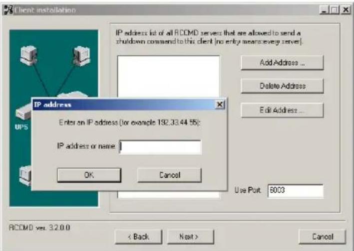
Figure 46: RCCMD Client Installation – IP-Address
The following window gives you the possibility to enable a periodical connection check and to attach a batch-file to be executed in the case of a failure.

Figure 47: RCCMD Client Installation – Connection check
With the following window you complete the installation by attaching batch-files to each action the RCCMD-client can receive from the CS121-adapter. Usually, you do not need to edit the default-values, because the installation already includes the batch-files as default. Just edit the batch-file, if you want to add or change an action to be executed.

Figure 48: RCCMD Client Installation – Batch-files
5.1.2 RCCMD client as relay station
In order to reach a bigger number of RCCMD receivers, the adapter needs to be operated as relay station. The receiver will be configured so that it will receive a RCCMD signal and this signal is then used to start a batch file, which then starts even more RCCMD sender signals. This computer is then sender and receiver at the same time and is therefore an important link in the UPS monitoring chain. Generally the use of an RCCMD client as relay stations makes the management of several 100 RCCMD clients far easier than configuring this via the Webbrowser interface of the CS121. Additionally, all Webbrowser Event configurations have a certain limitation so that you have to use the relay function if the number of jobs exceed e.g. 50 per event at the CS121 HW 131, at older CS121s even earlier.
See the following script, which lets the RCCMD-client act as relay station:
@ECHO off
REM --- Created by RCCMD configuration ---
SET path=C:\WINDOWS\;C:\WINDOWS\system32\;C:\RCCMD
SET path=*path\;C:\RCCMD\
RELAY RCCMD
<h1 id="this-batch-will-send-rccmd-shutdown-calls-to-the-the-ip-adresses-liste-below">This batch will send RCCMD shutdown calls to the the IP adresses liste below</h1>
<h1 id="at-the-end-of-the-batch-this-computer-will-initiate-the-local-shutdown">At the end of the batch this computer will initiate the local shutdown</h1>
rccmd -s -a 191.168.200.5
rccmd -s -a 191.168.200.6
rccmd -s -a 191.168.200.7
rccmd -s -a 191.168.200.8
rccmd -s -a 191.168.200.9
rccmd -s -a 191.168.200.10
rccmd -s -a 191.168.200.11
<h1 id="to-be-continued">to be continued ..</h1>
#
<h1 id="local-shutdown">local shutdown</h1>
ExitWin.exe shutdown force
@CLS
Figure 49: Example: Batch file to let the RCCMD act as relay station
5.1.3 License regulations
Please note that in order to use these functions legally, the corresponding RCCMD program is installed and started from the UPS-Management Software CD resp. see www.generex.de-download page for the latest version. (see above) The license code can only be used once per installation. If more computers need to be added to the shutdown process, additional licenses are required. The CS121-adapter package does usually contain a single licenses for RCCMD to shutdown 1 computer. For more computers to shutdown you have to order separate RCCMD client licenses. Generally the CS121 has an unlimited capacity to shutdown RCCMD clients, but if you have to enter more than 30-50 RCCMD clients via the Webbrowser interface it may make sense to use RCCMD relays (see above).
5.2 gChart
gChart is a GENEREX plug-in for the MS Internet Explorer available as a free download from the GENEREX web site. Quickly and easily visualise all of the CS121-adapter logfiles using Generex's ActiveX graphical log controller GChart when using the Internet Explorer. Discover UPS problems more easily and optimise system tuning more rapidly. Navigate through the data with the mouse using functions like zoom and pan with continuous motion in real time and query interpolated data values by clicking in the areas of interest. Customize the view by moving or toggling off the legend, toggle off and on the data grid and also switch individual log values on and off.
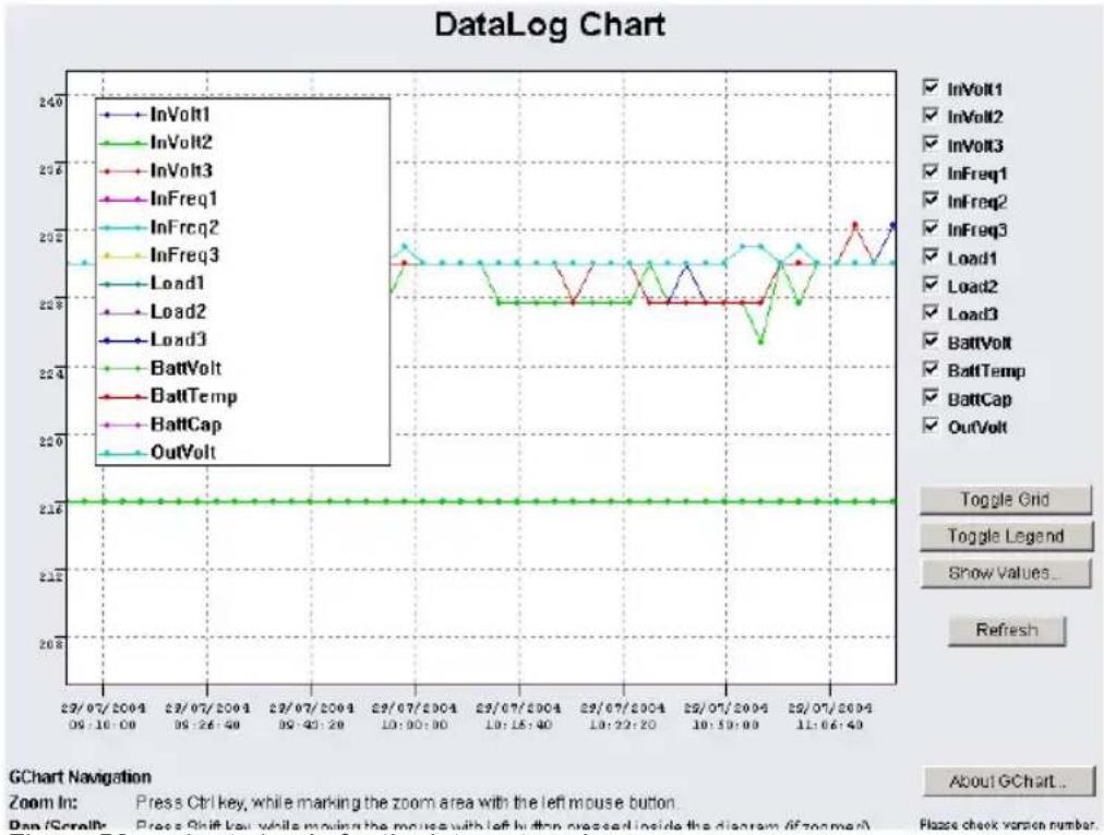
Get the gChart experience now by visiting our online CS121 at: http://q01.generex.de/ and be sure to follow the GChart logfile links.
5.3 UPS monitor (UPSMON)
UPS-Monitor (UPSMON) is the graphical monitoring and command interface application for UPSMAN and is available in standard and custom interfaces.
In order to display the UPSMAN provided data via the network customer friendly, the modules UPSMON and JAVAMON are delivered for free. The UPSMON is a client for all Microsoft platforms, whereas the JAVAMON can be started on all operating systems, that support JAVA. A LAN, WAN, or the Internet (TCP/IP) connection can be used as a connecting network between UPSMAN and the management interfaces. Both graphic interfaces can be customised to the demands of the UPS manufacturer, that's why the UPSMON appearance differs for almost every UPS maker product. This allows for an adaptation of all UPS systems with all different kinds of functions. UPS systems, with serial interfaces often incorporate of a variety of measured values and status information. Those can be displayed using overview or block diagrams. Other devices, such as diesel generators or extra measuring units can be integrated with this management software via the network. A separate password protected screen can be created, if the devices also support remote controlling commands. The values and status information, which are stored in the UPSMAN log file, can be requested from every computer with an installed UPS monitor module.
Features:
• Monitoring of all UPS systems that are connected in the network via UPSMAN and respective SNMP adapter
• gCHART dynamic visual log file graphic tool
- Remote controlling of all UPS systems via the network
• Graphic display of the UPS input data (voltage, power)
- Read out and display of the UPSMAN event-log files
- Programming of the UPSMAN scheduler
- Graphic screens containing all UPS information also under UNIX, MAC (JAVAMON)
6. CS121-Enhancements, Field of applications
6.1 SiteSwitch4 (SS4) and SiteSwitch4AUX (SS4AUX)
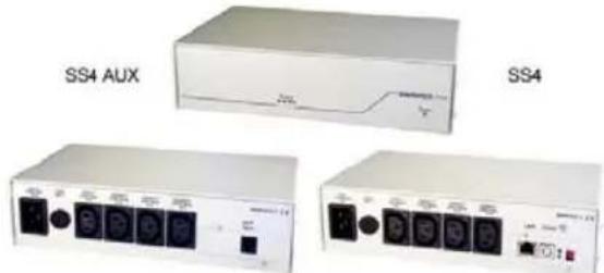
natural_image
Three electronic devices labeled SS4 AUX, SS4, and a control panel with ports (no visible text or symbols on the devices themselves)Figure 51: SideSwitch4 and SS4 AUX
SITEWITCH4AUX is a high-performed extension of the CS121-adapter but can also be operated as stand-alone solution with the possibility to connect to UPS or UPS-similar devices. The SITESWITCH has 4 power outputs sockets, which can be configured by the event settings of the CS121 or any other RCCMD compliant sender like SITEMANAGER, SITEMONITOR.
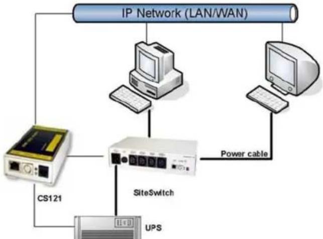
flowchart
graph TD
    A["IP Network (LAN/WAN)"] --> B["CPU"]
    A --> C["Computer"]
    A --> D["Computer"]
    B --> E["Power cable"]
    C --> E
    D --> E
    E --> F["SiteSwitch"]
    F --> G["UPS"]
    H["CS121"] --> F
    I["Power cable"] --> F
Figure 52: CS121-Installation with SideSwitch4
Using the integrated Webserver, the SITESWITCH 4 enables the monitoring and the remote control of its 4 power outputs. The power sockets can be switched on and off individually. This can be done either manually via the HTML browser interface or UPSMON or automatically using the EVENT manager of the CS121 - or any other network CS121 or compatible device. When executing the action using the EVENT manager of the CS121, the power switching can be preconfigured to run with delays or to run on a schedule. Both the UPSMON time scheduler and the HTML time scheduler can be used to configure a power switching time schedule. This task can also be achieved using the full version of the UNMS UPS Network Management Software.

Note: (only SS4, not SS4AUX) If you wish to use a UPS with your SS4 then you must install the appropriate CS121 Firmware on your SS4. The default Firmware on SS4 (OEMID 27) is for the usage without UPS, as standalone remote powerswitch. For UPS usage at the SS4 you must also be sure to set the Exchange COM Ports checkbox and then use the configuration cable to connect the SS4 with your UPS.
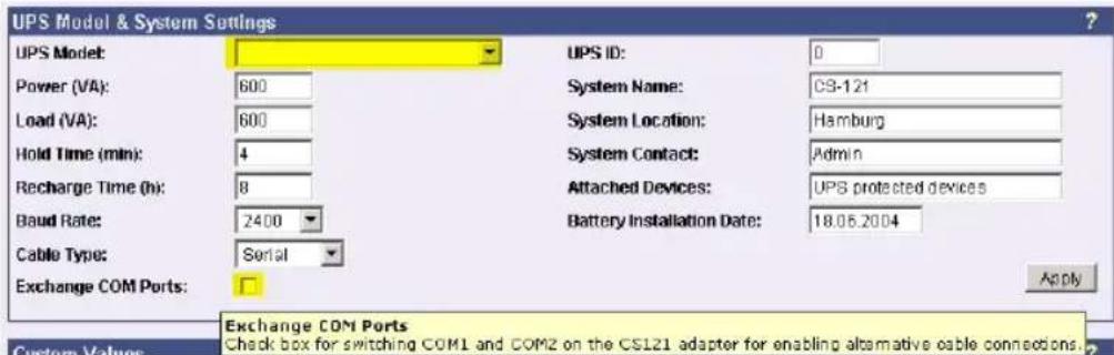
Figure 53: Exchange COM Ports 1 & 2 for SS4
6.1.1 SS4 Feature overview
- 4 configurable powers sockets with a breaking capacity of 230V/8A
• Power socket status indicator via HTML, UPSMON, UNMS or SNMP
• Control via the internal CS121 or via remote CS121 or RCCMD compatible devices - Remote control of the powers sockets via HTML Browser (Password protected)
• LED-Status of the power sockets - Small metal casing with 1.5RU, designed for 19"-Rack Mountings (mounting frame included)
• High breaking capacity (8A), input with IEC 16A. - Programmable power switching via the HTML and UPSMON Scheduler
- Delay of alarm (e.g. UPS alarms) triggered power switching on COM1 of the CS121
6.1.2 SS4 Contents
- SITESWITCH 4
• 16A IEC 230V power cable - 2 mounting irons for 19"-Rack installation
- manual for SS4
The manuals are being constantly updated and therefore the reader is encouraged to check our website for a newer download version of the adapter manual. Check http://www.generex.de for manual updates.
6.1.3 SS4 Installation
The power consuming devices are connected to the SS4 using IEC 250 VAC/6A plug cables. The SS4 has 4 IEC 250VAC/6A chassis sockets that can be switched on and off separately. Special notice is to be given to the 8A threshold breaking capacity; exceeding this limit will cause the SS4 fuse to break leaving all connected devices without electricity.

Note: Due to errors that may cause the switched off power outlet to remain on it is necessary to conduct the following: Before connecting any power consuming devices with the SITESWITCH 4 or working on any power consuming devices already connected to the SITESWTICH 4, make sure that the SITESWITCH 4 is not connected to the power supply by pulling its power cable out of the power socket.
Use the provided mounting irons to fix the SS4 into a 19" rack. Place the SS4 so that the front panel of the SS4 can be securely screwed onto the 19" rack housing while insuring also that the power cables can be connected from behind as well.
As soon as all of the power consuming devices are connected to the SS4, the IEC 16 power supply cable can be connected. Upon establishing power to the SS4, the green „POWER„ LED will light up, and the 4 „Power Socket Status LED“ one for each of the sockets should be unlit. This means that none of the sockets are being provided with power thus cutting the connected devices from the power supply.
The CS121 establishes a user interface for the SS4 for which the user has the option of using either UPSMON, Webbrowser, UNMS or an SNMP-Program. All communications take place either through a modem or network connection. Detailed information is covered in section 7.7.9 AUX and SS4 Settings.
6.1.4 SS4 - Technical data
Input voltage: 230V AC +/- 5%
Max. Power Input: 16A
Max. Power Output per socket: 8A (Load at cos phi 1)
Dimensions 260x180x60mm (BxTxH), with 19": 1,5U
Operating temperature: 0-40°C/rel.Humidity0-95% non condensating
6.2 Sensor SM\_T\_COM
The SM_T_COM is a temperature sensor for the use with a GENEREX CS121. It has a range from -25^ - 100^ Celsius (-13° -212° Fahrenheit) and comes with a 1.8 meter cable for connecting to the CS121 COM2 port. The SM_T_COM is designed for monitoring and management of 19"- racks, UPS rooms, server and data center rooms and for industrial applications. Simple Plug' n Play connections insure that the sensor can be easily and safely installed.
natural_image
White rectangular electronic device with a green port, no visible text or symbolsFigure 54: The Sensor SM_T_COM
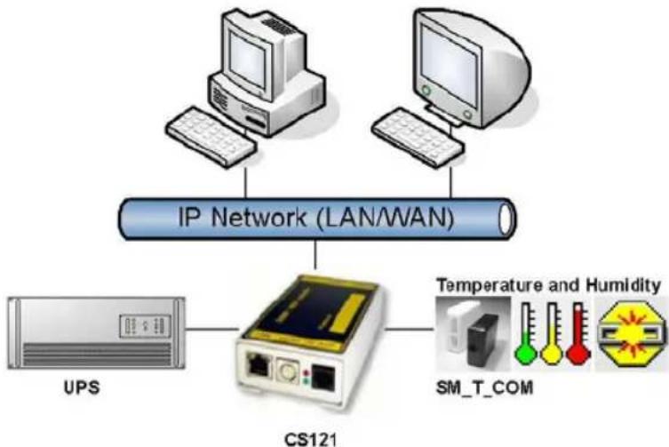
flowchart
graph TD
    A["UPS"] --> B["CS121"]
    C["IP Network (LAN/WAN)"] --> B
    D["Computer"] --> B
    E["Computer"] --> B
    F["Temperature and Humidity"] --> B
    G["SM_T_COM"] --> B
Figure 55: CS121-Installation with temperature SM_T_COM
The SM_T_COM (also available as SM_T_H – a combination of Temperature and Humidity) is a temperature sensor with an RS232 protocol which can be connected directly to the CS121 COM2 port. (Not BUDGET series).
The SM_T_COM shows the actual values on the CS121 Webserver screen and allows to trigger alarms, emails, messages in case the values exceed configurable thresholds. SM_T_COM is simply connected with the original CS121-TEMP cable (part of every CS121 SC and L) to the COM2. In the Webinterface COM2 & AUX you have to change to the COM2 mode to "SM_T_COM", press "apply" and "save&exit" and reboot to start the CS121 with your new settings. The Configuration of thresholds and Events is made via the Event-configuration windows and the SM_T_COM configuration page.
6.3 SENSORMANAGER
6.3.1 General information
If more than 1 or 2 environmental values are wanted to manage, than the SENSORANGER (SensorMan) is your choice. This device is a data measurement and collecting unit which allows the individual measurement and monitoring of 8 analog measurement devices (0-10V) and 4 digital alarm inputs or 4 outputs (open collectors).

natural_image
Exterior view of a server connected to a network interface (no visible text or symbols on the device body)Figure 56: Sensor Manager (SensorMan)
The SENSORMANAGER is a system extension for the CS121 series or for a Windows PC: Universal Remote Sensor Control Box for the monitoring of temperature, humidity and many other types of sensors as well as for the management of digital input/output signals. 8 analog inputs (0-10V), +4 digital input and/or outputs (48 V 500mA). Digital Outputs are configurable as normally open or as normally closed. Digital input connections directly through sensor for some models or connect directly to the RJ11 socket. Convenient splitting plug available for attaching two sensors to one RJ11 socket.
Purpose:
- Monitoring of temperatures, humidity and other analog data in computer rooms with automated response to system alarms.
- Alarms can be individually configured and defined for trip contacts such as fire, smoke and intrusion, and minimum/maximum thresholds values can be set for analog devices such as humidity, temperature and pressure, fluid level, etc. – any sensor which transmits its values between 0-10 V may be connected to a SENSORMANAGER.
- Data logging, logging of alarms, automatic shutdowns of network computers, and other actions can be set as reactions to critical alarms.
- All system operating and configuring can be done remotely via Web browser. The EVENT driven alarm management system of the CS121 informs the administrator of problems and may automatically switch off computers and other devices (Optional extensions: SITESWITCH 4 or SITEMANGER).
- The SENSORMANAGER is an extension to the CS121 Webmanager. If you want to connect any other computing device, please download the RS-232 protocol for the SENSOR MANAGER from our website and adjust your software to this communication type.
Important:
The SENSORMANAGER is compatible to the former TEMPMAN MI4. Users wishing to manage more than 4 temperatures must update the CS121 to Firmware 2.53 or higher. New firmware for your CS121 is available for download at: http://www.generex.de
6.3.2 Installation and Network integration

flowchart
graph LR
    A["UPS"] --> B["CS121"]
    B --> C["SensorMan"]
    C --> D["Temperature and Humidity"]
    C --> E["Pressure and Levels"]
    C --> F["Fire and Smoke"]
    C --> G["Motion and Intrusion"]
    D --> H["Input 4"]
    E --> I["Input 3"]
    F --> J["Input 2"]
    G --> K["Input 1"]
Figure 57: CS121-Installation with SENSORMANAGER
As shown in the figure above CS121 can also be applied to observe and react on alarms of the SENSORMANAGER-Inputs. Therefore, the CS121 COM2 port is connected and configured for the SensorManager's AUX- and Sensor-Input/Outputs. Within the CS121 configuration it is possible to define actions, which will be released from events of the SensorManager's devices.
6.3.3 SENSORMAN connections
For a detailed description of the Pin layout of the Input sockets see section in the appendix. Here, we give you an Example for some contacts:
- Alarm INPUT contact:
If the alarm contact INPUT is used, you may connect your alarm contact e.g. to Input 1 Pin 6 and Power supply Pin 1. In the CS121 you can configure that as a HIGH signal to the alarm is set – or the other way round.
- OUTPUT contact:
If you want to switch any relays or send high signals to the Output, you may connect your Output contact e.g. to Input 1 Pin 5 to your relays and configure the CS121 as "Output" for this signal. Now you may configure your Events in the CS121 to set the Output to HIGH or LOW.
- Sensor connection:
The sensor has to work within 0-10Volts, this may be connected directly to Channels 1-8, and the CS121 will now show the values in its Web browser. Alarm thresholds and actions may be configured via the EVENT manager of the CS121.
- Connecting the SENSORMANAGER unit:
The SensorMan has to be connected with the original configuration cable of the CS121 to COM 2.
The sensors for the SensorMan may be connected direct to the socket Inputs 1-4 using an RJ11 cable. In this configuration you can only use up to 4 sensors. If you want to use all 8 analog inputs, you have to use a splitting plug (optional) or connect the sensors directly to the Channel Inputs as described above.
If you use the sensor type SM, you may connect a second SM sensor to the input of the first SM. You can not connect more than 2 SM sensors in line.
For connecting an alarm contact to the SM-sensor, you may use the first or the second SM-contact input/output, but not both. Only one digital input/output is available per socket.
Other sensors: If you use other sensors than SM, EE or TM, you must use a splitting plug in order to connect more than one sensor to a single Input of the SensorMan.
6.3.4 Configuration
For setting up the sensors in the SensorMan make sure your configuration matches your sensor type, e.g. see example:
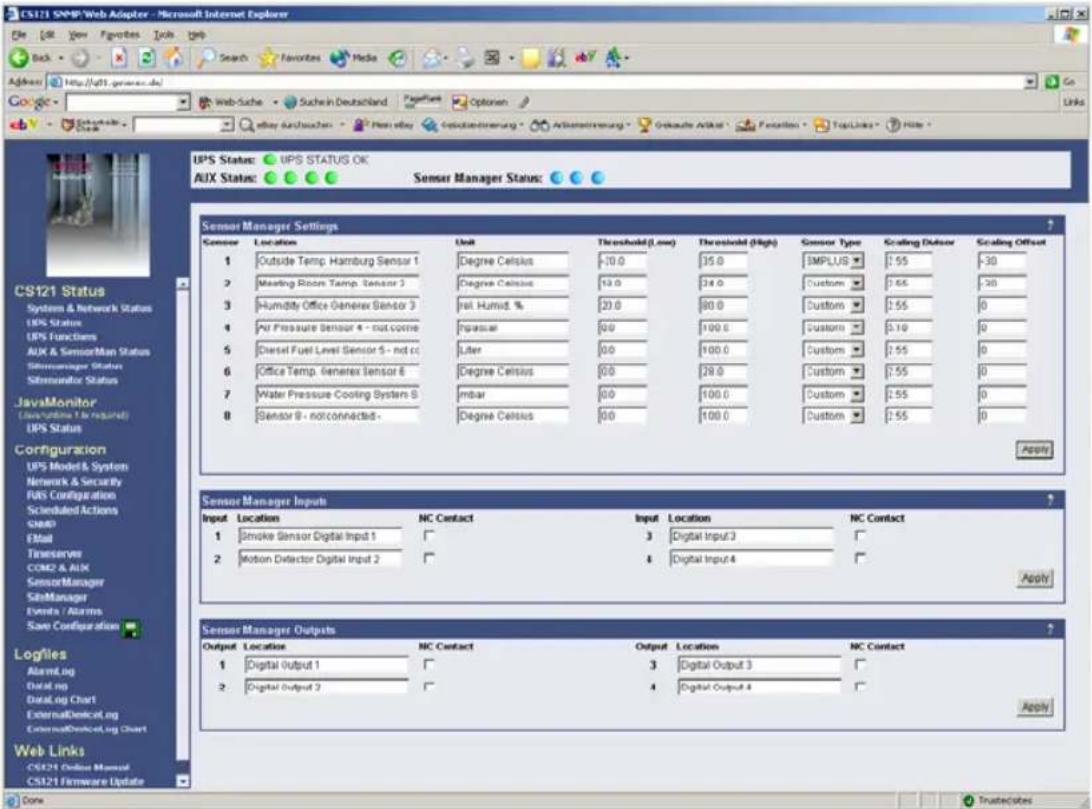
Figure 58: HTTP - SENSORMANAGER Settings
Using the splitting plugs (Part NO.SPSMRJ) it is possible to connect up to 8 sensors and 4 contacts to the SensorMan. A Mounting Kit (sold separately) is available for affixing the SensorMan to walls and railings.
The power supply for the SensorMan may also supply an external CS121 using a SM-CS121 type cable (sold separately) by simply connecting the Power-out of the SensorMan with the Power-in of the CS121 external.

Note: A combination of CS121 – SITESWITCH 4 SENSORMANAGER in a compact chassis is the SITEMANAGER – for more information about this Rackmonitoring and management device please refer to GENEREX website.
- Startup the Sensor Manager:
Connect the sensors to the SensorMan. Connect the SensorMan using the Mini8-DBSub9 cable to the COM 2 port of the CS121. Finally, plug the power supply into one of the UPS power outlets. Check the green LEDs on the bottom of the SensorMan; one should be flashing when reading data, and the other should be constantly lit. The flashing LED shows the requests from the CS121 – this means the installation is OK. The other LED shows that the device has started.

Note: You have to configure the CS121 COM2 port to "SensorMan" – otherwise the CS121 will not start making requests to the Sensor Manager.
When the SENSORMANAGER is running, you will see the values in the AUX section of the CS121 Web browser.
6.4 RASMANAGER
The RAS-Manager relays alarm signals coming from monitoring devices such as UPS, SiteManagers, contact alarms and the like to monitoring stations or email receivers. Any computer with RAS capabilities (Windows, Linux) can be used as a monitoring station. The only requirement is the setup of an PPPServer on the monitoring station. After the establishment of communications between the RAS-Manager and the monitoring station, a RCCMD signal is sent that depending on configuration can either make log entries, send emails and SMSs or execute programs.

flowchart
graph TD
    A["IP Network (LAN/WAN)"] --> B["RASManager"]
    B --> C["UPS"]
    B --> D["Computer"]
    B --> E["Computer"]
    B --> F["Phone"]
    B --> G["Phone"]
Figure 59: RASMANAGER network integration
6.5 LED-Matrix Display
The LED-Matrix display is a remote display unit for relaying RCCMD messages that can be operated via the Ethernet.
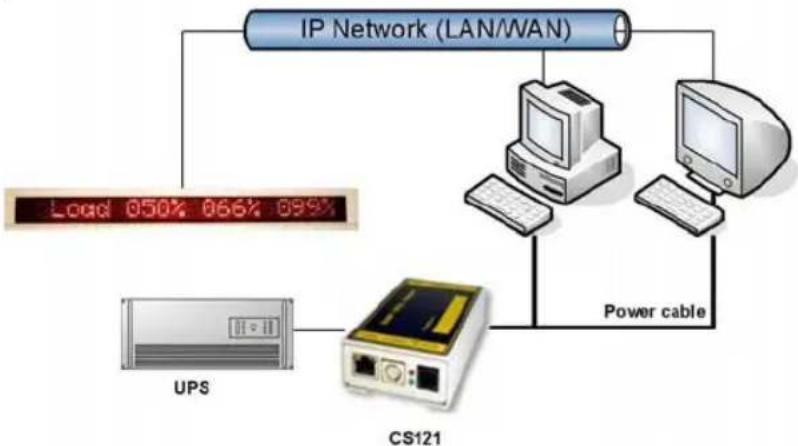
flowchart
graph TD
    A["IP Network (LAN/WAN)"] --> B["Power cable"]
    B --> C["Computer"]
    B --> D["UPS"]
    B --> E["CS121"]
    C --> F["Load 050% 066% 099%"]
Figure 60: LED-Matrix display network integration
Any device operating as an RCCMD Sender like a computer running UPSMAN software, RCCMD clients, CS121 Web managers and other RCCMD 2 compatible products can send text messages or environmental data values to the LED-Matrix and can add sounding alarms for warnings that require immediate attention. Users can also use the built in Web server interface of the LED-Matrix to relay alarms and messages without the use of an RCCMD Sender. The user simply enters the message into the Web browser that is to be relayed through the LED-Matrix.
6.6 MODBUS / PROFIBUS
- MODBUS
Modbus is a serial communications protocol for use with its programmable logic controllers (PLCs). It has become a de facto standard communications protocol in industry, and is now the most commonly available means of connecting industrial electronic devices. Modbus allows for communication between many devices connected to the same network, for example a system
that measures temperature and humidity and communicates the results to a computer. Modbus is often used to connect a supervisory computer with a remote terminal unit (RTU) in supervisory control and data acquisition (SCADA) systems.
The CS121-series (exclude BUDGET models) support MODBUS over IP and MODBUS over RS232 generally. Additionally, the CS121MODBUS-series also includes an RS485 interface at COM2, which can be connected to a 485Bus-system.

flowchart
graph TD
    A["UPS"] -->|Power cable| B["central building control system units"]
    C["CS121 MODBUS"] --> D["Modbus RS-485"]
Figure 61: CS121MODBUS Installation
• PROFIBUS
PROFIBUS (Process Field Bus) is the most popular type of fieldbus with more than 14 million nodes (2006) in use worldwide. PROFIBUS was defined in 1991/1993 as DIN 19245, moved in 1996 to EN 50170 and is since 1999 included in IEC 61158/IEC 61784 Standards.
To integrate the CS121 in a Profibus environment, GENEREX offers a Profibus gateway, which converts the MODBUS output of the CS121 into PROFIBUS environment.

flowchart
graph TD
    A["UPS"] -->|Power cable| B["central building control system units"]
    B --> C["CS121"]
    C --> D["Profibus Gateway"]
    D --> E["Profibus"]
Figure 62: CS121 PROFIBUS Installation
6.7 UNMS (UPS-Network Management System)
UNMS II is a UPS network monitor designed to inform you of emergency power supply systems problems before your clients, end-users or managers do. The UNMS as a limited version is part of every UPSMAN license (UPSMAN suite contains UPSMAN RS232/USB UPS Manager, UPSMON Windows client and UNMS 2 – limited to 9 UPS). The UNMS Server Service runs intermittent checks on UPS devices you specify. When problems are encountered, the UNMS Server Service can send notifications out to administrative contacts in a variety of different ways (For example: Email). Current status information, historical logs, and reports can all be accessed via a web browser (Web Console).
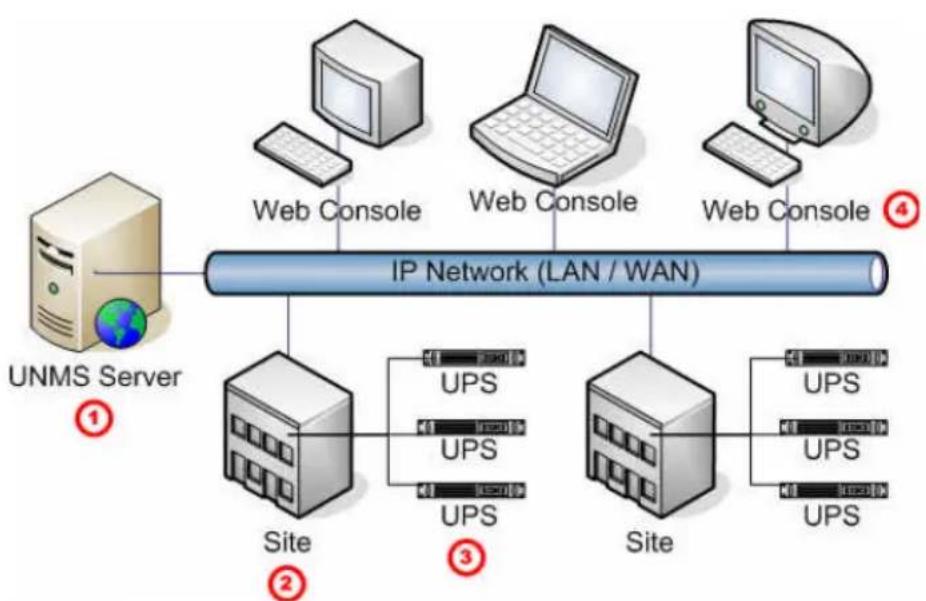
flowchart
graph TD
    A["UNMS Server"] --> B["IP Network (LAN / WAN)"]
    B --> C["Site"]
    B --> D["UPS"]
    B --> E["UPS"]
    B --> F["UPS"]
    B --> G["Site"]
    B --> H["UPS"]
    B --> I["UPS"]
    B --> J["UPS"]
    C --> K["Web Console"]
    D --> L["Web Console"]
    E --> M["Web Console"]
    F --> N["Web Console"]
    G --> O["Web Console"]
    H --> P["Web Console"]
    I --> Q["Web Console"]
| No. | Name | Description |
| 1 | UNMS Server | The UNMS Server Service and the related Web-Server installation. |
| 2 | Site | A user defined group of services (For example: UPS devices). |
| 3 | UPS | A single service (e.g. UPS device) that is monitored by the UNMS Server. |
| 4 | Web Console | Web-Consoles provide sharing of management information by many people. |
Figure 63: UNMS-Installation
MIB-Integration into your NMS
Standard-NMS Installations require for each device to be monitored its specific MIB (Management Information Base). To monitor the CS121 the Standard-MIB for UPS-systems, RFC1628, is generally to be integrated into your NMS.
To identify CS121 adapters in your network you may use the MAC address. The MAC address of every CS121 adapter starts with 00-03-05-02-XX-XX, whereas this address can be found in the Telnet menu (menu: IP address, gateway address, MIB system group).
Your SNMP adapter is now installed and fully functional. Please read the following for configuration and functionality descriptions of the adapter.
The MIB is to be loaded onto each SNMP Management Station that is monitoring an UPS via an UPS SNMP Agent. The MIB determines which UPS parameters can be monitored and controlled with the SNMP commands „get“ and „set“.
To complete the SNMP adapter installation and configuration process, you must compile the necessary MIBs to configure the NMS. Any NMS with a MIB compiler can manage the SNMP adapter.
Perform a „get" and a „set". If the get or set command fail, check the SNMP adapter access control. The manager must have read permission to execute a get command and read / write permission to execute a set command successfully.
For instructions on how to compile MIBs for the most popular NMSs - Novell's NetWare Management Station, Hewlett-Packard's OpenView Network Node Manager, and SunConnect; SunNet Manager; see the corresponding heading below.
Please note that the CS121 uses the standard MIB, which is included in most SNMP software already. This MIB is called UPSMIB and corresponds with the Standard RFC1628. In most cases compiling of the MIB is not required as it can be found under:
iso.org.dod.internet.mgmt.mib2.upsMIB
Please check your MIB directory before compiling the RFC1628!
Configure the NMS
- Set/compile the device MIB, if there is no standard UPS MIB RFC 1628 (CS121 only!)
- Add the SNMP adapter object to the management map and configuration of the events (e.g. message to the operator)
- Ping the SNMP adapter
Due to the different compilation procedures of the SNMP software products, it is not possible to explain the general procedures in greater detail. The compilation of a MIB file is explained in the general SNMP software manuals. Please contact the support, if you cannot resolve errors using this manual.
After the compilation the UPS software can be polled via a MIB browser and data can be read. Please choose the corresponding MIB variable or string of MIB variable and set the destination address TCP/IP of the adapter. The adapter will answer with the UPS data.
Alternatively the Windows UPSMON, JAVAMON or the UPS SNMP WATCH of the DataWatch Pro Software can be used. The UPS data will then be displayed graphically and internal UPS information, which are only useful to the technical support, will be hidden. In addition to this, the UPS SNMP WATCH is able to manage groups of UPS devices, in order to manage parallel redundant UPS systems.
As an optional add-on for the HP OpenView software, a snap-in may be ordered for UPSMAN/CS121.

Note: (SNAP-IN FOR HP OPENVIEW for WINDOWS NT, SNAP-IN FOR HP OPENVIEW for HP UNIX). This software implements itself into the HP Openview Node Manager surface and displays UPS devices as objects in the colors GREEN (OK), GREEN and RED (Alarm). With a mouse click, the graphic window starts (JAVAMON or Windows UPSMON) and displays current UPS data.
7. Troubleshooting - FAQ

Note: Since Troubleshooting and FAQs always need to be maintained and actualized to the latest software or firmware release, we show the latest informations only via our Website at www.generex.de. Please follow the according link.
Appendix
A. CS121 - Technical data
| Product Power Size Weight | Operating temperature | |||
| CS121L(Extern) | 12VDC300 mA. | 12,5 x 7 x 2,8 cm 210 | gr. < 40° | C |
| CS121SC(Slot chinese) | 13,5 x 6 x | 1,5 cm 66 gr. < 40°C | ||
| CS121F(Slot FUJI) | 7,5 x 8 x | 1,5 cm 64 gr. < 40°C | ||
| CS121R(Slot RIELLO) | 14,5 x 7,5 | x 1,5 cm 80 gr. < 40°C | ||
| CS121MOD(MODBUS Extern) | 12,5 x 7 x | 2,8 cm 210 gr. < 40°C | ||
| CS121BL(Budget Extern) | 12VDC300mA. | 12,5 x 7 x 2,8 cm 202 | gr. < 40°C | |
| CS121BSC(Budget Slot Chinese) | 12,5 x 7 x | 2,8 cm 59 gr. < 40°C |
| CS121-L CS121-C CS121 Slot | |||
| Power supply | 12 V DC 12 V DC | 12 V DC | |
| Power output | 350mA 100mA bei | 12V 100mA bei | 12V |
| Size | 69x126 mm | 69x126 mm | 60x120 mm |
| Ethernet connections | 10/ 100Base-T | 10/ 100Base-T | 10/ 100Base-T |
| RS-232 interface | 2 | 2 | 2 |
| LED's | 4 | 4 | 4 |
| DIP Switches | 2 | 2 | 2 |
| Operating temperature | 0 – 40 °C | 0 – 40 °C | 0 – 40 °C |
| Humidity during normal operations | 10-80%, no condensation | ||
B. CE- and UL-Certification
Both models, CS121L and CS121SC, are certificated by Underwriters Laboratories Inc. for the US and Canada with the power supply 12 V DC, 300 mA.
As well, for both hardware specifications 121 and 131 of CS121-Adapter a certification of Conformity has been drawn up. Please see the download page at www.generex.de to get a copy of the certifications and documents.
C. Cable and Circuit board configuration, Pin/AUX-Ports, SensorMan
CS121 Config cable
without Handshake
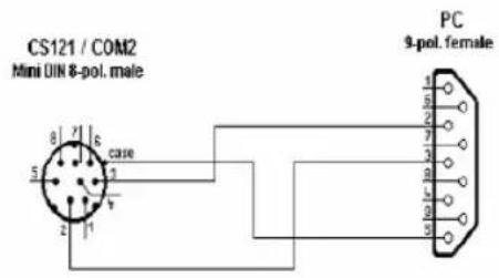
Figure 64: Cable configuration COM2
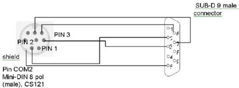
Figure 65: Cable type 113: CS121 adapter to modem
Pin Layout CS121 COM1:

Figure 66: External D-SUB 9-polig male
Pin1: DCD Pin6: DSR
Pin2: RxD Pin7: RTS
Pin3 TxD Pin8: CTS
Pin4 DTR Pin9: RI
Pin5 GND

Figure 67: Slot version: Circuit board connection
Pin1: -> GND
Pin2: -> VDD
Pin3: -> TxD
Pin4: -> RxD
Pin9: -> GND
Pin8 connected with Pin 10
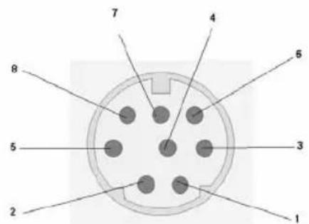
Figure 68: Pin COM2 Mini-DIN 8 pol
Mini DIN 8 socket RS-232:
Pin1: -> DCD
Pin2: -> RxD
Pin3: -> TxD
Pin4: -> DTR
Pin5: -> DSR
Pin6: -> RTS
Pin7: -> CTS
Pin8: -> RI
Schirm -> GND
RS-485 (optional):
Pin1: -> RS485-A
Pin5: -> RS485-B
RS-422 (optional):
Pin1: -> RS422-TX-A
Pin5: -> RS422-TX-B
Pin2: -> RS422-RX-A
Pin6: -> S422-RX-B
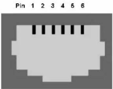
Figure 69: AUX-Port (Hardware Revision 1.1 = from Serial numbers 0121-1203, 0122-00198, 0123-00564 onwards) RJ11 6-pol
Pin1: -> +3,3V
Pin2: -> Input/Output 1
Pin3: -> Input/Output 2
Pin4: -> Input/Output 3
Pin5: -> Input/Output 4
Pin6: -> GND
The maximum input voltage is 3,3V. The input signals may be fed from external power sources or feed directly from Pin 1. If the external power supply delivers more than 5V a pre-resistor has to be fitted. The input resistance of the input is 5,1 kΩ
When using a opto coupler switch, a Pull up resistor of 1,5kOhm has to be used.
Output-voltage: If configured as OUTPUT, every Pin delivers 3.3 Volt/10mA.


Figure 70: Example (Inputs): Opener or closer contact (only on hardware model CS121)

Figure 71: Opto coupler logic

Figure 72: Example (Outputs)
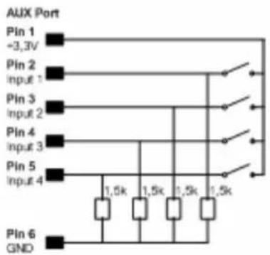
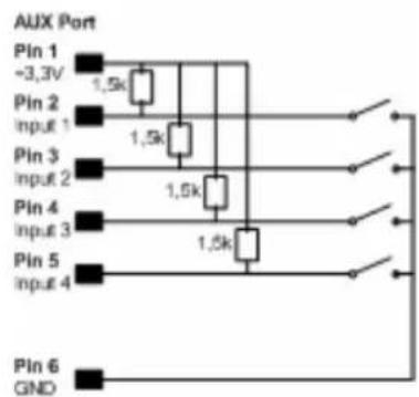
Figure 73: Examples: AUX Output on hardware model CS131 only
D. MODBUS Interface
D.1. General information
For remote control and monitoring of devices the MODBUS interface in each CS121 M can read out measurement values, events, status and other information in a master-slave protocol.

Note: Please note that not all UPS models support all or specific measurement values (e.g. battery low).
D.2. Available Modbus Function Codes
Implemented MODBUS functions in the CS121 M units:
| 01H | Read | Coils | |
| 02H Read Discrete Inputs | |||
| 03H Read Holding Registers | |||
| 04H | Read | Input | Registers |
| 05H Write Single Coil | |||
Which functions are supported depends on the connected UPS. For standard UPS only functions 03H and 04H are available. In this case the CS121 M makes no difference between function 03H and 04H. The baud rate is adjustable up to 115200 Baud.

Note: Please note that the MODBUS adapter client allows a timeout of 40ms at 9600 baud for one value.
D.3. Exception Codes
Except for broadcast messages, when a master device sends a query to a slave device it expects a normal response. One of four possible events can occur from the master's query:
If the slave device receives the query without a communication error, and can handle the query normally, it returns a normal response.
If the slave does not receive the query due to a communication error, no response is returned. The master program will eventually process a timeout condition for the query.
If the slave receives the query, but detects a communication error parity, LRC, or CRC, no response is returned. The master program will eventually process a timeout condition for the query.
If the slave receives the query without a communication error, but cannot handle it (for example, if the request is to read a non existent register the slave will return an exception response informing the master of the nature of the error.
Available Exception codes:
| Code Meaning | |
| 01H | Illegal Function:The command received in the query is not defined. |
| 02H | Illegal Address:The address received in the query is not defined for the slave. |
| 04H | Slave DeviceInternal slave device error. |
Failure:
D.4. MODBUS Modes in the CS121 M (ASCII and RTU)
MODBUS Command
The following tables contain the general command descriptions and examples with ASCII and RTU framing.
Read Words (Functions 03h and 04h)
For the CS121 there is normally no difference between these two functions.
Query:
| slave no | function code | address of first word to read | word count | Checksum | LRC or CRC | ||
| 1 byte | 1 byte | High byte | Low byte | High byte | Low byte | 1 or 2 byte(s) | |
| A | n | s | w | e | r | |
| slave no | function code | Byte count | high byte of first word | low byte of first word | bytes with contents of n words | Checksum LRC or CRC |
| 1 byte | 1 byte | 1 byte | 1 byte | 1 byte | n * 2 bytes | 1 or 2 byte(s) |
Example: Read Words, Function 04h, ASCII Mode
Read one word at address 63h (= 99 decimal):
Query:
| Byte | 1 | 2, 3 | 4, 5 | 6, 7 | 8, 9 | 10, 11 | 12, 13 | 14, 15 | 16 | 17 |
| Mea-ning | Leading colon | Slave num-ber | Func-tion code | address of first word to read | word count to read | LRC | Carria ge return | line feed LF | ||
| high byte | low byte | high byte | low byte | |||||||
| ASCII | : | 0 1 | 0 4 | 0 0 | 6 3 | 0 0 | 0 1 | 9 7 | ||
| HEX | [3A] | [30][31] | [30][34] | [30][30] | [36][33] | [30][30] | [30][31] | [39][37] | [0D] | [0A] |
Answer:
| Byte | 1 | 2, 3 | 4, 5 | 6, 7 | 8, 9 | 10, 11 | 12, 13 | 14 | 15 |
| Mea-ning | leading colon | Slave number | function code | byte count | content s of the word | LRC | carriag e return | line feed LF | |
| high byte | low byte | ||||||||
| ASCII | : | 0 1 | 0 4 | 0 2 | 1 2 | 3 4 | B 3 | ||
| HEX | [3A] | [30][31] | [30][34] | [30][32] | [31][32] | [33][34] | [42][33] | [0D] | [0A] |
ASCII: Data, which will send over the link as ASCII characters.
HEX: Hexadecimal values of the data
→ The word at address contains the value 1234h = 4660 decimal.
Example: Read Words, Function 04h, RTU Mode
Read one word at address 63h (= 99 decimal):
Query:
| Byte | 1 | 2 | 3 | 4 | 5 | 6 | 7 | 8 | ||
| Meaning | silent interval >= 3.5 characters | Slave number | function code | address of first word to read | word count to read | CRC | silent interval >= 3.5 characters | |||
| high byte | low byte | high byte | low byte | low byte | High byte | |||||
| RTU HEX | [01] | [04] | [00] | [63] | [00] | [01] | [C1] | [D4] | ||
Answer:
| Byte | 1 | 2 | 3 | 4 | 5 | 6 | 7 | |
| Meani | silent | Slave | function | byte | Content | CRC | Silent |
| ng | interval >= 3.5 characters | number | code count of | the word | interval >= 3.5 characters | ||||
| RTU HEX | high | byte | low byte | low byte | high byte | ||||
| [01] [04] | [02] [12] | [34] | [B4] [47] | ||||||
→ The word at address contains the value 1234h = 4660 decimal.
D.5. UPS Parameter
Standard UPS – Address Description
Please note that this is just an example for a typical UPS, not every UPS has all these values, some UPS may have more, some less. Please contact your UPS manufacturer to check which variables are available and which requests are not supported.
Note: "Type U/S": this defines whether the answer has an algebraic sign (math. +/-) or not. U means "unsigned". S means "signed", this answer may be positive or negative.
| Address | Type | Function | Name Description Length | ||
| 100 U | 3 / 4 | OUTP | 0WER0 Outpower Phase 1 1 | ||
| 101 U | 3 / 4 | OUTP | 0WER1 Outpower Phase 2 % | 1 | |
| 102 U | 3 / 4 | OUTP | 0WER2 Outpower Phase 3 % | 1 | |
| 103 U | 3 / 4 | BATT | CAP Battery Capacity % | 1 | |
| 104 | S | 3 / 4 | INVOLT0 | Input Voltage Phase 1 V | 1 |
| 105 | S | 3 / 4 | INVOLT1 | Input Voltage Phase 2 V | 1 |
| 106 | S | 3 / 4 | INVOLT2 | Input Voltage Phase 3 V | 1 |
| 107 | S | 3 / 4 | TEMPDEG | Temperature C° | 1 |
| 108 S | 3 | / 4 | AUTONOMTIME | Autonomy Time minutes | 1 |
| 109 U | 3 / 4 | STATUS | UPS Status (ASCII HEX)Please note UPSMANstatusbytes table below | 1 | |
| 10 | S | 3 / 4 | BATTVOLT | Battery Voltage V | 1 |
| 111 U | 3 / 4 | INFREQ0 | Input Frequency Hz Phase 1 | 1 | |
| 112 U | 3 / 4 | INFREQ1 | Input Frequency Hz Phase 2 | 1 | |
| 113 U | 3 / 4 | INFREQ2 | Input Frequency Hz Phase 3 | 1 | |
| 114 U | 3 / 4 | CNT_PF | Power fail Counter | 1 | |
| 115 U | 3 / 4 | Alarm Battery Bad | 1 = active; 0 = not active | 1 | |
| 116 U | 3 / 4 | Alarm: On Battery | 1 = active; 0 = not active | 1 | |
| 117 U | 3 / 4 | Alarm: Battery Low | 1 = active; 0 = not active | 1 | |
| 118 U | 3 / 4 | Alarm: Battery Depleted | 1 = active; 0 = not active | 1 | |
| 119 U | 3 / 4 | Alarm: Over temperature | 1 = active; 0 = not active | 1 | |
| 120 U | 3 / 4 | Alarm: Input Bad | 1 = active; 0 = not active | 1 | |
| 121 U | 3 / 4 | Alarm: Output Bad | 1 = active; 0 = not active | 1 | |
| 122 U | 3 / 4 | Alarm: Output Overload | 1 = active; 0 = not active | 1 | |
| 123 U | 3 / 4 | Alarm: On Bypass | 1 = active; 0 = not active | 1 | |
| 124 U | 3 / 4 | Alarm: Bypass Bad | 1 = active; 0 = not active | 1 | |
| 125 U | 3 / 4 | Alarm: Output Off as requested. | 1 = active; 0 = not active | 1 | |
| 126 U | 3 / 4 | Alarm: UPS Off as requested. | 1 = active; 0 = not active | 1 | |
| 127 U | 3 / 4 | Alarm: Charger Failed | 1 = active; 0 = not active | 1 | |
| 128 U | 3 / 4 | Alarm: UPS Output Off | 1 = active; 0 = not active | 1 | |
| 129 U | 3 / 4 | Alarm: UPS System Off | 1 = active; 0 = not active | 1 | |
| 130 U | 3 / 4 | Alarm: Fan Failure | 1 = active; 0 = not active | 1 | |
| 131 U | 3 / 4 | Alarm: fuse failure | 1 = active; 0 = not active | 1 | |
| 132 U | 3 / 4 | Alarm: general fault 1 = active; 0 = not active 1 | ||
| 133 U | 3 / 4 | Alarm: diagnose test failed 1 = active; 0 = not active 1 | ||
| 134 U | 3 / 4 | Alarm: communication lost 1 = active; 0 = not active 1 | ||
| 135 U | 3 / 4 | Alarm: awaiting power 1 = active; 0 = not active 1 | ||
| 136 U | 3 / 4 | Alarm: shutdown pending 1 = active; 0 = not active 1 | ||
| 137 U | 3 / 4 | Alarm: shutdown imminent 1 = active; 0 = not active 1 | ||
| 138 U | 3 / 4 | Alarm: test in progress 1 = active; 0 = not active 1 | ||
| 139 U | 3 / 4 | AUX Port 1 1 = active (high)0 = not active (low) | 1 | |
| 140 U | 3 / 4 | AUX Port 2 1 = active (high)0 = not active (low) | 1 | |
| 141 U | 3 / 4 | AUX Port 3 1 = active (high)0 = not active (low) | 1 | |
| 142 U | 3 / 4 | AUX Port 4 1 = active (high)0 = not active (low) | 1 | |
| 143 U | 3 / 4 | Mesurement sensor 1 | Analog value 1 |
| Section OEM NEWAVE UPS | |||||
| 139 U | 3 / 4 | Manual Bypass Switch Closed | 0 = open1 = closed | 1 | |
| 140 U | 3 / 4 | OUTPUT_VOLT0 | Output voltage Phase 1 | 1 | |
| 141 U | 3 / 4 | OUTPUT_VOLT1 | Output voltage Phase 2 | 1 | |
| 142 U | 3 / 4 | OUTPUT_VOLT2 | Output voltage Phase 3 | 1 | |
| 143 U | 3 / 4 | Output Current Phase A * 10 | Output Current Phase 1 in Ampere *10 | 1 | |
| 144 U | 3 / 4 | Output Current Phase B * 10 | Output Current Phase 1 in Ampere *10 | 1 | |
| 145 U | 3 / 4 | Output Current Phase C * 10 | Output Current Phase 1 in Ampere *10 | 1 | |
| 146 U | 3 / 4 | xid30 17 Bits 0-15 | Status bit of UPS 1 = true, 0 = false | 1 | |
| 147 U | 3 / 4 | xid30 17 Bits 16-31 | Statusbit, for details please contact NEWAVE | 1 | |
| 148 U | 3 / 4 | xid64 5 Bits 0-15 | Alarmbit, for details please contact NEWAVE | 1 | |
| 149 U | 3 / 4 | xid64 5 Bits 16-31 | Alarmbit, for details please contact NEWAVE | 1 | |
| 150 U | 3 / 4 | xid64 5 Bits 32-47 | Alarmbit, for details please contact NEWAVE | 1 | |
| 151 U | 3 / 4 | xid64 5 Bits 48-63 | Alarmbit, for details please contact NEWAVE | 1 | |
| Section OEM MASTERGUARD | ||||
| 139 U | 3 / 4 | PXWARN | 2 | |
| 141 U | 3 / 4 | FAULT CODE 1 | 1 | |
| 142 U | 3 / 4 | FAULT CODE 2 | 1 | |
| 143 U | 3 / 4 | FAULT CODE 3 | 1 | |
| 144 U | 3 / 4 | FAULT CODE 4 | 1 | |
| 145 U | 3 / 4 | BADBATTBLOCK 1 | 1 | |
| 146 U | 3 / 4 | BADBATTBLOCK 1 | 1 | |
| 147 U | 3 / 4 | BADBATTBLOCK 1 | 1 | |
| 148 U | 3 / 4 | BADBATTBLOCK 1 | 1 | |
| 149 U | 3 / 4 | BADBATTBLOCK 1 | 1 | |
| 150 U | 3 / 4 | BADBATTBLOCK 1 | 1 | |
| Section OEM RITTAL | |||||
| Digital Input Status(DI) | |||||
| 0 bit | 2 Bypass working Status 0: Normal, Status 1: Alert 1 | ||||
| 1 bit | 2 Bypass Interruption Status 0: Normal, Status 1: Alert 1 | ||||
| 2 bit | 2 Rectifier Failure Status 0: Normal, Status 1: Alert 1 | ||||
| 3 bit | 2 Inverter Failure Status 0: Normal, Status 1: Alert 1 | ||||
| 4 bit | 2 Over Temperature Status 0: Normal, Status 1: Alert 1 | ||||
| 5 bit | 2 Over Load Status 0: Normal, Status 1: Alert 1 | ||||
| 6 bit | 2 0 Status 0: Normal, Status 1: Alert 1 | ||||
| 7 bit | 2 Battery Voltage too Low Status 0: Normal, Status 1: Alert 1 | ||||
| 8 bit | 2 Fuse broken Status 0: Normal, Status 1: Alert 1 | ||||
| 9 | bit | 2 Battery discharging Status 0: Normal, Status 1: Alert | 1 | ||
| 10 | bit 2 Status 0: Floating charge Status 1: Instant charging | 1 | |||
| 11~30 | bit 2 For future expansion | 1 | |||
| After 31 | bit 2 Venders own definition | 1 | |||
| Analog Measurement point(AI) | |||||
| 00 | word | 4 R phase input voltage | 0.1 Volt | 2 | |
| 01 | word | 4 S phase input voltage | 0.1 Volt | 2 | |
| 02 | word | 4 T phase input voltage | 0.1 Volt | 2 | |
| 03 | word | 4 R phase input current | 0.1A | 2 | |
| 04 | word | 4 S phase input current | 0.1A | 2 | |
| 05 | word | 4 T phase input current | 0.1A | 2 | |
| 06 | word | 4 Input frequency | 0.1Hz | 2 | |
| 07 | word | 4 R phase output voltage | 0.1 Volt | 2 | |
| 08 | word | 4 S phase output voltage | 0.1 Volt | 2 | |
| 09 | word | 4 T phase output voltage | 0.1 Volt | 2 | |
| 10 | word | 4 R phase out current | 0.1A | 2 | |
| 11 | word | 4 S phase output current | 0.1A | 2 | |
| 12 | word | 4 T phase output current | 0.1A | 2 | |
| 13 | word | 4 Output frequency | 0.1Hz | 2 | |
| 14 | word | 4 Battery voltage | 0.1 Volt | 2 | |
| 15 | word | 4 0 | 0.1A | 2 | |
| 16 | word | 4 Battery temperature#1 | 0.1deg C | 2 | |
| 21~31 | word | 4 For future expansion | 2 | ||
| After 32 | word | 4 Vendor self definition | |||
| Digital output(DO)Function 1 to read data; 5 to control the function | |||||
| 0 bit | 1 / 5 UPS Turn On | ||||
| 1 bit | 1 / 5 UPS Shut down | ||||
| 2 bit | 1 / 5 Alarm Reset | ||||
| 3 bit | 1 / 5 Battery Instant Charging | ||||
| 4 bit | 1 / 5 Battery Floating Charging | ||||
| 5~10 | bit | For future expansion | |||
| After | Vender self definition | ||||
Other OEM's ->See OEM MODBUS Documentation
UPSMAN Status Bytes - Standard Device Status Bits
| UPS Status Hex-Value Description | ||
| UPS_SB_BYPASS_MODE 0x0001 | power piped thru | |
| UPS_SB_SHUTDOWN | 0x0002 | shutdown |
| UPS_SB_OUTPUT_ACT | 0x0004 | inverter on |
| UPS_SB_BACKUP_MODE | 0x0008 | battery power |
| UPS_SB_BATTERY_LOW 0x0010 | low battery err | |
| UPS_SB_OVER_TEMP 0x0020 | over temp err | |
| UPS_SB_TEST_ACT | 0x0040 | test in progress |
| UPS_SB_INPUT_HIGH 0x0080 | over power err | |
| UPS_SB_OUTPUT_HIGH 0x0100 | over load err | |
| UPS_SB_INVERTER_FAILURE | 0x0200 Inverter error | |
| UPS_SB_BATTERY_BAD | 0x0400 | Battery error |
| UPS_SB_ECO_MODE | 0x0800 eco - bypass | |
| UPS_SB_INVERTER_WARN | 0x1000 eco - bypass | |
| UPS_SB_UPS_FAILED | 0x2000 | prser flag |
| UPS_SB_COMM_LOST | 0x4000 | for snmp |
| UPS_SB_DVG_ALARM | 0x8000 | SiteManager/SiteMonitor |
D.6. Bus termination
It is necessary to set the last bus device on the RS-485 Bus jumper for the bus termination. The jumper is already set in newly delivered adapters. Please remove the 4 screws at the underside of the adapter in order to open the box. You will find the jumper J1 near the network connector. Default is ON = CS121 is last device. If you take off the Jumper, then the CS121 can be used inside a group of chained devices.
D.7. Configuration
Please use Telnet (network connection) for the configuration with the default IP address 10.10.10.10. Put DIP switch 1 into the "OFF" position. If you have a RS-232/RS-485 converter available you can also use a HyperTerminal via COM2 with both DIP switches in the "OFF" position.
D.8. TCP/IP - UDP Ports
The following are ports of the CS121 SNMP Adapter. These are the ports that have to be made available in the Firewall in order to use all of the CS121 functions:
| Echo | 7/tcp |
| echo | 7/udp |
| ftp-data | 20/tcp |
| ftp | 21/tcp |
| telnet | 23/tcp |
| smtp | 25/tcp |
| http | 80/tcp |
snmp 161/udp
snmptrap 162/udp
time (rfc868) 37/tcp
time (sntp) 123/tcp
rccmd 6003
Upsmon 5769
Modbus over IP 502/tcp
D.9. MODBUS Cables
The following cable (Cable 112) is used for connecting the Schneider Electrics TSX SCY CM6030 MODBUS device and the CS121 MODBUS adapter.
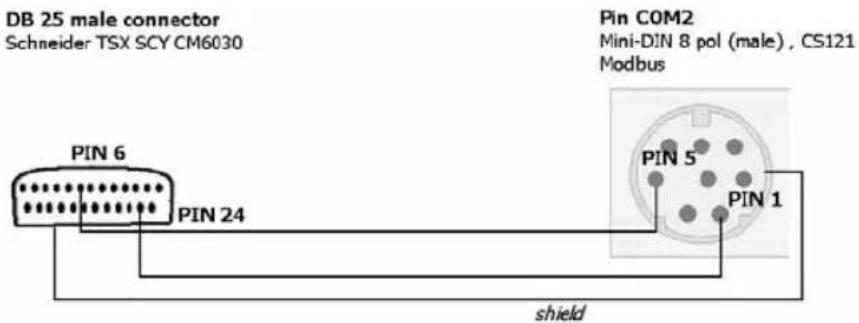
Figure 74: MODBUS - Cable 112
NOTE: it is very important that the Shield is connected to the MINI 8 housing and to the MODBUS requesting device common ground!
E. Available Variables of the CS121

Note: Not all variables are supported from all UPS-models. Please try the use of the variable to see, whether your UPS supports the variable or not.
| Variable Meaning | |
| OUTPUT_VOLT | Output voltage - only supported from specified USV manufactures |
| OUTPUT_CURRENT | Output currency |
| SECSONBATT | Seconds, since the event power outage has been released |
| STATUS | Actual UPS state |
| INVOLT | Input voltage |
| INCURR | Input currency |
| BATTVOLT | Battery voltage |
| TEMPDEG | Ambient or operating temperature – depends on the UPS-Model |
| AUTONOMTIME | Power-on time left over under actual charge |
| BATTCAP | Capacity of the battery in percent |
| OUTPOWER | Power of charge in percent |
| INFREQ | Input frequency |
| OUTFREQ | Output frequency |
| CONNECT | ID of the used UPS protocol |
| CABLE ID of the used cable type | |
| POWER | Configurated UPS Power |
| LOAD | Configurated Load |
| HOLDTIME Configurated hold time | |
| RECHARGETIME Configurated time for a complete battery charging | |
| MODEL UPS model name | |
| TIMEREMAIN | Resttime (AUTONOMTIME-POWERREMAIN) |
| LOCALTIME | Local timestamp |
| OUTPHASES | Output phase |
| INPHASES | Input phase |
| LOCATION | UPS-Adapter location |
| DATE | Date |
| TIME | Time |
| ATTACHED_DEVICES | Attached devices |
| MANUFACTURER | Manufacturer |
| TEMP1, ..., TEMP8 | Actual measurement for sensors 1-8, used for SensorMan settings only |
| TEMP1LOCATION, ..., TEMP8LOCATION | Configurated sensor 1-8 location |
| TEMP1UNIT, ..., TEMP8UNIT | Configurated sensor 1-8 unit |
| CUSTOM1TEXT, ..., CUSTOM6TEXT | Configurated Custom Text 1-6 |
F. Pin layout of Input-sockets of the SENSORMANAGER unit
INPUT 1:
Pin 1 Input Voltage 9-24Volt +
Pin 2 Analog Channel 1 (0-10V+)
Pin 3 Analog Channel 5 (0-10V+)
Pin 4 Ground
Pin 5 OUTPUT: Open collector OUT 9-24 V, max. 30mA
Pin 6 INPUT: Digital Input 9-24V
INPUT 2:
Pin 1 Input Voltage 9-24Volt +
Pin 2 Analog Channel 2 (0-10V+)
Pin 3 Analog Channel 6 (0-10V+)
Pin 4 Ground
Pin 5 OUTPUT: Open collector OUT 9-24 V, max. 30mA
Pin 6 INPUT: Digital Input 9-24V
INPUT 3:
Pin 1 Input Voltage 9-24Volt +
Pin 2 Analog Channel 3 (0-10V+)
Pin 3 Analog Channel 7 (0-10V+)
Pin 4 Ground
Pin 5 OUTPUT: Open collector OUT 9-24 V, max. 30mA
Pin 6 INPUT: Digital Input 9-24V
INPUT 4:
Pin 1 Input Voltage 9-24 Volt +
Pin 2 Analog Channel 4 (0-10V+)
Pin 3 Analog Channel 8 (0-10V+)
Pin 4 Ground
Pin 5 OUTPUT: Open collector OUT 9-24 V, max. 30mA
Pin 6 INPUT: Digital Input 9-24 V
Index
RJ45, 11
Table of figures
Figure 1: Connectors of the CS121....11
Figure 2: DIP-Switches: CS121L (left) in configuration mode (IP 10.10.10.10) and CS121SC (right) in normal mode .... 12
Figure 3: CS121 in a network environment .... 13
Figure 4: HTTP - Administrator login 16
Figure 5: HTTP - UPS Model & System Settings 16
Figure 6: HTTP - Network & Security Settings 17
Figure 7: Terminal communication settings....17
Figure 8: Telnet - Main Menu....18
Figure 9: Telnet - IP Settings 18
Figure 10: Telnet - UPS Settings....19
Figure 11: HTTP – Adapter reboot dialog....20
Figure 12: HTTP – Job Editor – Introduction....22
Figure 13: HTTP - System & Network Status 23
Figure 14: HTTP - UPS Status ...... 23
Figure 15: HTTP - UPS Functions....24
Figure 16: HTTP - AUX & SensorMan Status....24
Figure 17: HTTP - UPS Model & System 25
Figure 18: HTTP - Network & Security Settings 26
Figure 19: HTTP - Email Settings....27
Figure 20: HTTP - Timeserver Settings 28
Figure 21: MS-Timeservices....29
Figure 22: HTTP - Event Configuration with tool tip 30
Figure 23: HTTP - Event Editor 30
Figure 24: HTTP – Event Editor, Example of a Shutdown-Configuration .... 30
Figure 25: HTTP – Treshold event ...... 31
Figure 26: HTTP - Job Editor: Logfile-entry 31
Figure 27: HTTP - Job Editor: Email-Job 32
Figure 28: HTTP - Job Editor: Continuous event job 32
Figure 29: HTTP - Job Editor: RCCMD Shutdown ...... 34
Figure 30: HTTP - Job Editor: RCCMD execute/command 35
Figure 31: HTTP – Enable RCCMD Listener....35
Figure 32: HTTP - Job Editor: RCCMD-Command.... 36
Figure 33: HTTP - Job Editor: RCCMD-Trap....37
Figure 34: HTTP - Job Editor: Shutdown UPS-Job 37
Figure 35: HTTP - Job Editor: Switch AUX-Port 37
Figure 36: HTTP - Job Editor: Wake on LAN....38
Figure 37: HTTP - Scheduled Actions with warning 38
Figure 38: HTTP - SNMP....39
Figure 39: HTTP - COM2 Mode overview ....40
Figure 40: HTTP - COM2 & AUX with TEMPMAN 41
Figure 41: HTTP – Sensor Manager Settings....43
Figure 42: HTTP - RAS Manager Settings 43
Figure 43: HTTP - Firmware Update Page 46
Figure 44: CS121-configuration settings via ftp....47
Figure 45: RCCMD - Overview....50
Figure 46: RCCMD Client Installation – IP-Address 51
Figure 47: RCCMD Client Installation – Connection check....51
Figure 48: RCCMD Client Installation – Batch-files....52
Figure 49: Example: Batch file to let the RCCMD act as relay station ....52
Figure 50: gchart plug-in for the internet explorer....53
Figure 51: SideSwitch4 and SS4 AUX 54
Figure 52: CS121-Installation with SideSwitch4.... 54
Figure 53: Exchange COM Ports 1 & 2 for SS4 55
Figure 54: The Sensor SM T COM.... 56
Figure 55: CS121-Installation with temperature SM_T_COM 56
Figure 56: Sensor Manager (SensorMan).... 57
Figure 57: CS121-Installation with SENSORMANAGER 58
Figure 58: HTTP - SENSORMANAGER Settings .... 59
Figure 59: RASMANAGER network integration 60
Figure 60: LED-Matrix display network integration....60
Figure 61: CS121MODBUS Installation 61
Figure 62: CS121 PROFIBUS Installation....61
Figure 63: UNMS-Installation 62
Figure 64: Cable configuration COM2 65
Figure 65: Cable type 113: CS121 adapter to modem....65
Figure 66: External D-SUB 9-polig male 65
Figure 67: Slot version: Circuit board connection....65
Figure 68: Pin COM2 Mini-DIN 8 pol....66
Figure 69: AUX-Port (Hardware Revision 1.1 = from Serial numbers 0121-1203, 0122-00198, 0123-00564 onwards) RJ11 6-pol .... 66
Figure 70: Example (Inputs): Opener or closer contact....67
Figure 71: Opto coupler logic 67
Figure 72: Example (Outputs) 67
Figure 73: Example (AUX Output at cables with more than 10 m)....67
Figure 74: MODBUS - Cable 112....74

- UPS WEB/SNMP MANAGER
- Limited Warranty
- Copyright:
- English Manual
- Contents
- English Manual 3
- The CS121 family - Introduction 6
- Quickstart 15
- Configuration of the CS121
- The CS121 family - Introduction
- About your CS121
- General information
- Functionalities of your CS121
- About the communication with the CS121-Adapter
- - MODBUS
- • SNMP
- - TCP
- The CS121 Adapter Package
- 1.5
- CS121
- overview
- A typical installation - CS121 in a network environment
- Connect your CS121 ...
- ... via serial port
- CS121BSC:
- Configuration cable (not CS121BL/BSC):
- ... via LAN
- Verifying the CS121 connectivity
- - UPS-Status displays (LEDs)
- • Network status LEDs
- • Ping the SNMP-Adapter
- Quickstart
- Setting up basic network configuration
- 2.1.1
- Using
- HTTP/Webbrowser
- Using Telnet / MS-HyperTerminal
- Building up a connection
- Main menu & IP-Settings
- 2.1.2.3
- UPS
- Settings
- Save configuration
- Adapter-restart and boot procedure
- Introduction in the event configuration
- About same basic events
- - Powerfail
- - System shutdown
- - Battery low
- - UPSMAN started
- Quickguide to install an RCCMD-job
- CS121 Status-Monitors
- Configuration
- UPS Model & System
- Network & Security
- 3.2.4
- Timeserver
- Events / Alarms
- Event Configuration
- Treshold events
- Logfile entries
- RCCMD Jobs
- License regulations:
- 3.2.5.4.1
- RCCMD
- Shutdown
- Job Editor
- 3.2.5.4.2
- Message
- 3.2.5.4.3
- Execute/command
- Example of use 1: CS121-adapter as RCCMD-listener
- Example of use 2: CS121-adapter switches an output
- 3.2.5.4.6
- Trap
- UPS shutdown
- AUX-Port
- Wake on LAN (WOL)
- Scheduled Actions
- SNMP
- • Network Server Settings
- - Configuring Trap-receivers
- - SNMP Trap Test
- - Configuration Mode:
- - Pipe-Through Mode 1:
- - Pipe-Through Mode 2:
- • TEMPMAN & SENSORMANAGER:
- - RAS-Mode
- AUX and SITESWITCH4 Settings
- SENSORMANAGER
- RAS Configuration
- Save Configuration / Reboot
- Reading the Alarm-Logfile
- Adapter Software-Updates (Firmware)
- Firmware Update Page
- Firmwareupdate via Setup-tool
- Firmwareupdate via FTP
- Firmware flash renewal and recovery
- Instructions for recovery procedure:
- Changing the Adapter's MAC-Address
- - GENEREX MAC Identifier - Address code:
- Additional Software
- RCCMD
- Installation
- RCCMD client as relay station
- License regulations
- gChart
- UPS monitor (UPSMON)
- Features:
- CS121-Enhancements, Field of applications
- SiteSwitch4 (SS4) and SiteSwitch4AUX (SS4AUX)
- SS4 Feature overview
- SS4 Contents
- SS4 Installation
- SS4 - Technical data
- Sensor SM\_T\_COM
- SENSORMANAGER
- General information
- Purpose:
- Important:
- Installation and Network integration
- SENSORMAN connections
- Configuration
- RASMANAGER
- LED-Matrix Display
- MODBUS / PROFIBUS
- • PROFIBUS
- UNMS (UPS-Network Management System)
- MIB-Integration into your NMS
- Troubleshooting - FAQ
- Appendix
- CE- and UL-Certification
- MODBUS Interface
- D.1. General information
- D.2. Available Modbus Function Codes
- D.3. Exception Codes
- D.4. MODBUS Modes in the CS121 M (ASCII and RTU)
- D.5. UPS Parameter
- D.6. Bus termination
- D.7. Configuration
- D.8. TCP/IP - UDP Ports
- D.9. MODBUS Cables
- Available Variables of the CS121
- Pin layout of Input-sockets of the SENSORMANAGER unit
- Index
- Table of figures
Brand : AEG
Model : SNMP Network Adaptor
Category : Network card / adapter