
MK1 (1969) - Automobile JAGUAR - Free user manual and instructions
Find the device manual for free MK1 (1969) JAGUAR in PDF.


| Product Type | Automobile (Car) |
| Brand | Jaguar |
| Model | MK1 (1969) |
| Body Style | 4-door saloon |
| Engine | 2.4L or 3.4L inline-6, petrol |
| Transmission | 4-speed manual |
| Power Output | 112–210 bhp (depending on variant) |
| Dimensions (L x W x H) | 4600 mm x 1700 mm x 1450 mm |
| Wheelbase | 2730 mm |
| Kerb Weight | Approx. 1500 kg |
| Fuel System | Carburetor |
| Brakes | Front disc, rear drum |
| Suspension | Independent front, live rear axle |
| Steering | Recirculating ball |
| Fuel Tank Capacity | Approx. 70 litres |
| Fuel Consumption | Approx. 15 L/100 km |
| Seating Capacity | 5 |
| Top Speed | Approx. 160 km/h (100 mph) |
| Primary Use | Classic car driving and preservation |
| Maintenance | Regular oil changes, spark plug replacement, carburetor tuning |
| Safety Features | Seat belts (lap), lockable glove box |
| Spare Parts Availability | Widely available through classic car specialists |
Frequently Asked Questions - MK1 (1969) JAGUAR
User questions about MK1 (1969) JAGUAR
0 question about this device. Answer the ones you know or ask your own.
Ask a new question about this device
Download the instructions for your Automobile in PDF format for free! Find your manual MK1 (1969) - JAGUAR and take your electronic device back in hand. On this page are published all the documents necessary for the use of your device. MK1 (1969) by JAGUAR.
USER MANUAL MK1 (1969) JAGUAR
Owners Workshop Manual
natural_image
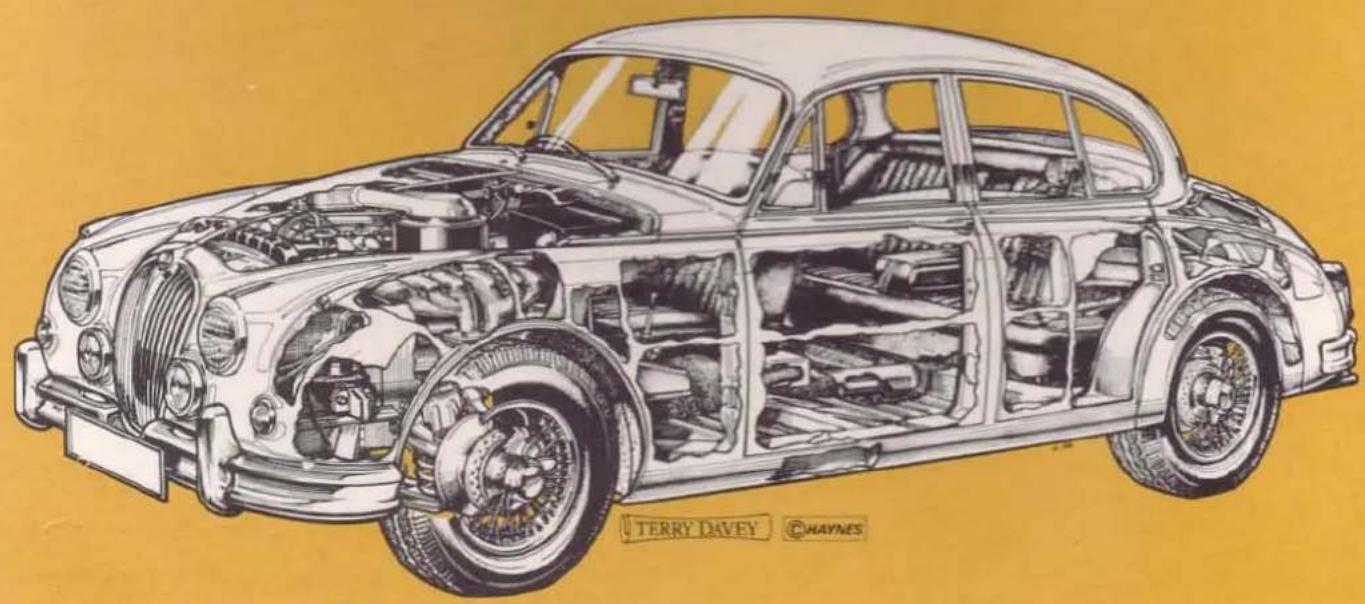
Cutaway illustration of a classic sedan showing internal engine and wheel components (no text or symbols)Jaguar Mk 1 and 2 240 and 340 Owners Workshop Manual
by J H HAYNES
Associate Member of the Guild of Motoring Writers
and BILL HARPER
Models covered
2483 cc. Jaguar 2.4 Mk 1 Saloon. Introduced October 1955.
Superceded by Jaguar 2.4 Mk 2 Saloon. Introduced October 1959.
Superceded by Jaguar 240 Saloon. Introduced September 1967.
Discontinued October 1969.
3442 cc. Jaguar 3.4 Mk 1 Saloon. Introduced February 1957.
Superceded by Jaguar 3.4 Mk 2 Saloon. Introduced October 1959.
Superceded by Jaguar 340 Saloon. Introduced September 1967.
Discontinued September 1968.
3781 cc. Jaguar 3.8 Mk 2 Saloon. Introduced October 1959.
Discontinued during 1967.
Special equipment models plus manual and automatic transmission.
SBN 900550 98 8
© J H Haynes and Company Limited 1973
1182/096

J H HAYNES AND COMPANY LIMITED SPARKFORD YEOVIL SOMERSET
distributed in the USA by
HAYNES PUBLICATIONS INC.
9421 WINNETKA AVENUE
CHATSWORTH LOS ANGELES
CALIFORNIA 91311 USA
Acknowledgements
Our first thanks must go to Jaguar Cars British Leyland UK Limited of Coventry for allowing us to use some of their illustrations and for being most forthcoming with certain technical information.
Castrol Limited and Champion Limited have been helpful with lubrication and spark plug details respectively.
Brian Horsfall stripped the car with his usual dexterity and Les Brazier took photographs at many angles.
John Murphy has page edited this manual and our thanks must go to him.
Special note: The supply of illustrations and material by Jaguar Cars British Leyland UK Limited does not imply that Jaguar Cars has approved the contents of this book or is in any way responsible for the accuracy of any information printed. The copyright in illustrations and other technical material provided by Jaguar Cars British Leyland UK Limited remains vested in that company.
About this manual
The aim of this book is to help you get the best value from your car. It can do so in two ways. First it can help you decide what work must be done, even should you choose to get it done by a garage; the routine maintenance and the diagnosis and course of action when random faults occur. But it is hoped that you will also use the second and fuller purpose by tackling the work yourself. This can give you the satisfaction of doing the job yourself. On the simpler jobs it may even be quicker than booking the car into a garage and going there twice, to leave and collect it. Perhaps most important, much money can be saved by avoiding the costs a garage must charge to cover their labour and overheads.
The book has drawings and descriptions to show the function of the various components so that their layout can be understood. Then the tasks are described and photographed in a step by step sequence so that even a novice can cope with complicated work. Such a person is the very one to buy a car needing repair yet be unable to afford garage costs.
The jobs are described assuming only normal spanners are available, and not special tools. But a reasonable outfit of tools will be a worthwhile investment. Many special workshop tools produced by the makers merely speed the work, and in these cases guidance is given as to how to do the job without them, the oft quoted example being the use of a large hose clip to compress the piston rings for insertion in the cylinder. But on a very few occasions the special tool is essential to prevent damage to components, then their use is described. Though it might be possible to borrow the tool, such work may have to be entrusted to the official agent.
To avoid labour costs a garage will often give a cheaper repair by fitting a reconditioned assembly. The home mechanic can be helped by this book to diagnose the fault and make a repair using only a minor spare part. The classic case is repairing a non-charging dynamo by fitting new brushes.
The manufacturer's official workshop manuals are written for their trained staff, and so assume special knowledge; detail is left out. This book is written for the owner, and so goes into detail.
The book is divided into twelve Chapters. Each Chapter is divided into numbered sections which are headed in bold type between horizontal lines. Each section consists of serially numbered paragraphs.
There are two types of illustration: (1) Figures which are numbered according to Chapter and sequence of occurrence in that Chapter. (2) Photographs which have a reference number on their caption. All photographs apply to the Chapter in which they occur so that the reference figure pinpoints the pertinent section and paragraph number.
Procedures, once described in the text, are not normally repeated. If it is necessary to refer to another Chapter the reference will be given in Chapter number and section number thus: Chapter 1/16.
If it is considered necessary to refer to a particular paragraph in another Chapter the reference is eg, 'Chapter 1/5:5'. Cross references given without use of the word 'Chapter' apply to sections and/or paragraphs in the same Chapter, eg, 'see Section 8' means also 'in this Chapter'.
When the left or right side of the car is mentioned it is as if looking forward from the drivers seat.
Great effort has been made to ensure that this book is complete and up to date. The manufacturers continually modify their cars, even in retrospect.
Whilst every care is taken to ensure that the information in this manual is correct no liability can be accepted by the authors or publishers for loss, damage or injury caused by any errors in or emissions from the information given.
Contents
| Chapter | Section | Page | Section | Page |
| Introduction | 4 | Lubrication chart | 8 | |
| Recommended lubricants | 7 | Routine maintenance | 9 | |
| Ordering spare parts | 7 | |||
| 1 Engine | General description | 21 | Decarbonisation | 48 |
| Removal | 21 | Reassembly | 54 | |
| Dismantling | 29 | Valve clearances | 57 | |
| Examination and renovation | 42 | Replacement | 61 | |
| 2 Cooling system | Draining | 64 | Water pump | 68 |
| Flushing and filling | 65 | Fan belt | 68 | |
| Thermostat | 66 | Anti-freeze | 70 | |
| 3 Fuel system and carburation | General description | 74 | Gauge unit | 78 |
| Fuel pump | 75 | Carburettors | 79 | |
| Petrol tank | 78 | |||
| 4 Ignition system | Contact breaker | 96 | Ignition timing | 99 |
| Distributor | 98 | Spark plugs | 100 | |
| 5 Clutch and actuating mechanism | Bleeding | 104 | Master cylinder | 113 |
| Removal | 106 | Slave cylinder | 114 | |
| Refitting | 109 | Fault finding | 115 | |
| 6 Gearbox | Removal and replacement | 120 | Overdrive | 131 |
| Dismantling | 120 | Fault finding | 142 | |
| Examination | 127 | Automatic transmission | 142 | |
| Reassembly | 127 | Fault diagnosis | 146 | |
| 7 Propeller shaft | Removal and replacement | 154 | Universal joints | 156 |
| Centre bearing | 154 | |||
| 8 Rear axle | Removal and replacement | 162 | Differential reassembly | 171 |
| Differential removal | 164 | |||
| 9 Braking system | Bleeding | 174 | Disc brakes | 180 |
| Front brakes | 177 | Handbrake | 183 | |
| Rear brakes | 178 | Master cylinder | 186 | |
| Wheel cylinders | 179 | Servo unit | 187 | |
| 10 Electrical system | Battery | 193 | Lighting equipment | 204 |
| Dynamo | 194 | Windscreen washer | 206 | |
| Starter motor | 197 | Heater | 207 | |
| Voltage regulator | 198 | Horn | 207 | |
| Fuses | 202 | Electric clock | 208 | |
| Flasher unit | 203 | Wiring diagram | 212 | |
| Windscreen wiper | 203 | |||
| 11 Suspension | Front suspension | 223 | Steering | 234 |
| Anti-roll bar | 230 | Power assisted steering | 244 | |
| Rear road springs | 233 | Front wheel alignment | 255 | |
| 12 Bodywork and underframe | Maintenance | 259 | Heater | 271 |
| Body repair | 259 | Exhaust system | 271 | |
| Windscreen | 266 | Wheels and tyres | 273 | |
| Bumpers | 269 |
Introduction to the
Jaguar Mks1 and 2, 240 and 340
The Jaguar 2.4 Mk 1 introduced in October 1955 was a departure. A departure for the Jaguar Company and a departure for the dulled post war years of motoring. After a considerable time of development the Jaguar 2.4, using Jaguar's XK engine (decreased in stroke), gearbox and steering gear of strong repute, appeared as a new monocoque construction; all previous Jaguar models having the conventional separate body and chassis. The 2.4 was an exciting car by the post war standards - over 100 mph performance, reasonable economy, great comfort and a very 'slippery' shape all at a price of £1269 and 10 pence including purchase tax, all in a 1955 4 door saloon.
It was not until February 1957 that the Mk 1 saloons really became significant. The full XK engine of the time, the 3.4 was installed in the same 2.4 bodyshell. Then in September of that year, 4 wheel disc brakes, wire wheels, automatic transmission and overdrive were available as options. It was now possible to buy from the showroom a luxury 4 door saloon and have one of the fastest (120 mph), best braked and most stylish cars available, all for about £1600.
October 1959 saw the next significant announcement. The Mk 2 series appeared supplemented by the 3.8 litre saloon. This was an even more powerful version, now with 220 bhp and a limited slip differential as standard. The visual changes were a slightly larger bodywork, much larger rear screen and higher door pillars on the same waist line giving a 'taller' appearance. Internally the Mk 2 had a wider rear back, improved front suspension, disc brakes as standard, dual exhaust system and many interior improvements. Until September 1967 many minor changes took place but the basic three cars remained. Power steering was made available.
The 3.8 was discontinued in September 1967 whilst the 2.4 became the 240 and the 3.4, the 340. (The 3.4 and 3.8 'S' types introduced in 1963 continued after 1967. They are not dealt with in this manual although their specification is somewhat similar). The 240 and 340 are very similar to the earlier models, although some trim was removed and an 'E' type type cylinder head was installed on both models. Production of the 340 stopped in September 1968, the 240 in October 1969.
The Mk 1 and 2 series is a very significant car in the annals of motoring. It finally convinced the world that performance, comfort and reasonable economy could be had from a 4 door saloon at a very competitive price without any loss of tractibility and carrying capacity. From a competition point of view it also showed that production saloon cars can handle racing speeds. Anyone who has seen four 3.8 saloons, two dark blue and two in off-white, with head lamps blazing driven by four grand prix drivers sweeping round 90^ bends in perfectly controlled four wheel drifts, will know just what is meant by this.

natural_image
Black-and-white photo of a vintage sedan parked outdoors on grass, with trees and a stone wall in the background (no visible text or symbols)Jaguar 3.4 Mk 1. This shows the Special Equipment model with wire wheels. The date is 1957.
natural_image
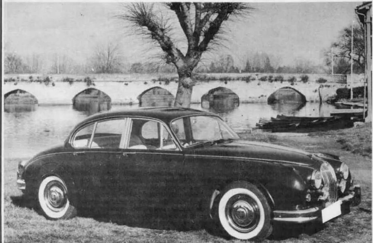
Black-and-white photo of a vintage sedan parked near water with floating structures and a tree in the background (no visible text or symbols)Jaguar 3.8 Mk 2. Note the larger window area, thinner door pillars and optional white wall tyres. All Mk 2 models had cutaway rear wheel spats even with disc wheels.

natural_image
Black-and-white photo of a classic 19th-century sedan parked outdoors, no visible text or symbols on the car body.Jaguar 240. There is little external difference between this model and the Mk 2 except for less lavish wheel trims and grilles instead of the additional driving lamps. The date is 1968.
natural_image
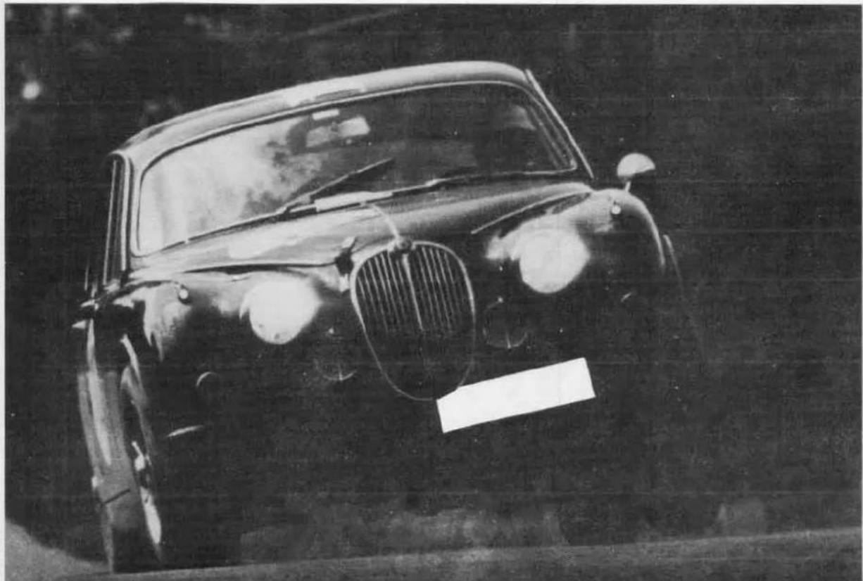
Black-and-white photo of a vintage car with large windows and grille, parked on a road (no visible text or symbols)A famous photograph of a very successful racing 3.8 from Germany. There was very little external modification necessary.
Recommended lubricants
The following table gives details of the lubricants recommended by the manufacturer.
Almost all lubricating oils contain additives and although it is permissible to mix recommended brands it is an undesirable practice. If you wish to change from one brand to another it is advisable to wait until the sump or gearbox are drained and then to follow the Oil Company's recommendations in regard to flushing procedures before refilling with the different make of oil. In cases where the grade or make of oil in the engine or gearbox is not known, our advice is that you drain off and refill with a known make and grade rather than run the risk of sludge formation and gumming up.
| COMPONENT | TYPE OF LUBRICANT OR FLUID | CORRECT CASTROL PRODUCTS | |||||||
| Engine ... ... ... ... ... | 20W/50 Multigrade engine oil ... | ... | ... | CASTROL GTX | |||||
| Upper cylinder lubrication | ... | ... | CASTROLLO | ||||||
| Distributor oil can points) Oil can lubrication ) | ... | ... | High quality Multigrade engine oil | ... | ... | CASTROL GTX | |||
| Gearbox) Rear axle) | ... | ... | High quality 90EP Hypoid gear oil | ... | ... | CASTROL HYPOY | |||
| Steering box | ... | ... | High quality 90EP Hypoid gear oil | ... | ... | CASTROL HYPOY | |||
| Front wheel bearings) Rear wheel bearings) Distributor cam ) | ... | ... | Lithium based high melting point grease | ... | ... | CASTROL LM GREASE | |||
| Steering tie-rods) Wheel swivels) Door hinges ) | ... | ... | Lithium based high melting point grease | ... | ... | CASTROL LM GREASE | |||
| Automatic transmission unit) Power steering system ) | ... | ... | Approved automatic transmission fluid | ... | ... | CASTROL TQF | |||
Recommended Hydraulic Fluid
Castrol Girling Universal Brake and Clutch Fluid is recommended. This fluid conforms to specification SAE 70 R3 which is specially modified for additional safety to give a higher boiling point. Where those makes are not available, only fluid guaranteed to conform to specification SAE 70 R3 may be used as an alternative.
Ordering spare parts
Although spare parts can be ordered through any garage it obviously makes good sense to go straight to a Jaguar dealer where you will find that the storeman is more familiar with your car and your requirements and there is a better chance that they can supply you ex-stock.
When ordering new parts it is essential that you give full information about your particular model of Jaguar otherwise it cannot be guaranteed that you will be supplied with the correct part and there is nothing more frustrating than to find that a part, for which you may have had to wait some time due to supply difficulties, will not fit.
It is imperative therefore, that the car and engine numbers, together with any prefix or suffix letters are quoted when ordering parts. If the unit in question is the gearbox or overdrive then the gearbox number and any prefix or suffix letters must also be quoted. Look at the item you are replacing, it may have a part number stamped on it. If so, quote this number when ordering or better still take the part along with you for correct
identification.
The car number is stamped in the bonnet catch channel forward of the radiator header tank.
The body number is stamped on a plate attached to the right hand side of the scuttle.
The above identifications are also stamped on a plate situated in the engine compartment as shown.
The engine number is stamped on the right hand side of the cylinder block above the oil filter and at the front of the cylinder head casting.
The gearbox number is stamped on a shoulder at the left hand rear corner of the gearbox casing and also on the top cover.
If you intend using the Jaguar exchange scheme, make sure that the component you wish to exchange is clean and is complete to the standard of the exchange item before taking it in to the stores; needless to say you should have removed those items not supplied with the exchange component.
Lubrication chart

Routine maintenance
Periodic servicing of your car should be looked upon as an essential, not only for the purpose of obtaining economy and the best performance from the vehicle, but also for ensuring safety and for finding defects at an early date before anything serious, and probably expensive, occurs. You will find that by far the largest element of the maintenance routine is a purely visual examination which will take up very little time.
The maintenance instructions which follow are those recommended by the manufacturer and they are supplemented by additional tasks which we have found, from practical experience, need to be carried out as a purely preventative measure.
The servicing periodicity recommended by the Manufacturers for the 2.4, 3.4 and 3.8 litre models is tied to a 2500 mile cycle as opposed to a 3000 mile cycle for the 240 and 340 models. This difference is reflected in the mileages quoted in the following servicing schedules.
Daily before use
1 Remove the dipstick and check the engine oil level which should be up to the "MAX" mark. Top up as necessary.
2 Remove the radiator filler cap, when the engine is cold, and top up the coolant as necessary.
3 Top up the windscreen washer bottle.
4 Look at the level of brake fluid in the reservoir. The level of the fluid will be readily seen at a quick glance by noting the position of the float needle. Investigate the cause if frequent topping up is necessary.
5 Check correct operation of services-horn, windscreen wipers, windscreen washer and lights.
Weekly
1 Check tyre pressures. See Chapter 12.
Monthly
1 Check condition of tyres for compliance with legal limits of wear and condition. But, depending on mileage covered and road conditions, this check may be necessary at more frequent intervals.
2 Check the level of electrolyte in the battery. Check the battery connections for security and cleanliness. See Chapter 10.
Every 2500/3000 miles (4000/5000 km)
1 Drain the oil from the engine sump by removing the plug at the right hand rear corner of the sump as shown in Fig.RM.1. Do this work when the engine is warm so that the oil will flow more
freely.
2 Refer to Chapter 1. Remove and discard the oil filter element. Thoroughly clean the canister, the spring, central rod and pressure plate. Fit a new filter element of the correct type for your car. Renew the circular rubber seal in the filter head, this seal will be supplied with the new filter element.
3 Clean and replace the sump drain plug. Refill the sump with engine oil using one of the makes and grades recommended in the chart at the end of this Section.
Note: Where the car is used for low speed driving, stop/start driving particularly in cold weather where the choke is used more than is normal, or long periods of use in dusty conditions, the oil should be changed at least every 1000 miles (1600 km). 4 Remove the moulded cap at the top of the distributor by springing back the two clips. Remove the rotor arm and apply a few drops of engine oil around the screw "A" in Fig.RM.2. Do not remove the screw. Apply one drop of oil on the post "B" and smear the cam "C" with grease very lightly. Lubricate the centrifugal advance mechanism through the aperture at the edge of the contact breaker base plate. Be very careful not to get any oil or grease on the contact breaker points.
5 Examine the contact breaker points and if they are burned or blackened, clean them with a fine carborundum stone or very fine emery cloth. You will have to remove them to do this work and Chapter 4 gives full instructions on how it is done.
6 Turn the engine until the contact breaker points are fully open, check the gap using clean feeler gauges. The gap should be 0.014" - 0.016" (0.36 - 0.41 mm) and, if adjustment is required, refer to Chapter 4 where full instructions will be found for dealing with the type of distributor fitted to your car.
7 Remove the spark plugs, clean them and reset the gap to 0.025" (0.64 mm). It is advisable to have the plugs cleaned by a garage with a machine specially designed for the purpose.
8 On those cars not fitted with an automatic fan belt tensioner, check and adjust the tension of the fan belt (Fig.RM.3). You should be able to get about 12 " movement on the belt at the point of its longest run.
9 Unscrew the cap on the top of the carburettor suction chambers (SU carburettors) and lift out the damper valve which is attached to the cap. Fill the hollow piston spindle with SAE 20 oil.
10 The idling speed of the engine should be about 700 rpm. If adjustment is required, refer to Chapter 3 and carry out the adjustment as required for the type of carburettor fitted.
11 Place the car on level ground and check the level of oil in the gearbox. This is done by removing the combined level and filler plug on the left hand side of the gearbox. Thoroughly clean all dirt from around the plug before taking it out. The level of oil should be to the bottom of the filler hole. Top up as necessary with one of the makes and grades of oil given in the chart at the end of this Section. Topping up the gearbox will also fill the overdrive unit (if fitted) but extra care is required to ensure that no dirt gets in with the oil if equipped with an overdrive unit.
12 The propeller shaft universal joints fitted to later model cars are of the "sealed for life" type but on early models provided with grease nipples at the joints give a few strokes with a grease gun to lubricate the roller bearings.
13 Check the level of oil in the rear axle with the car standing on level ground. A combined level and filler plug is provided in the rear cover of the axle casing as shown in FigRM.4. Clean all dirt away from the plug before you take it out. The level of oil should be to the bottom of the filler plug hole. Top up as necessary with a hypoid oil of the correct grade.
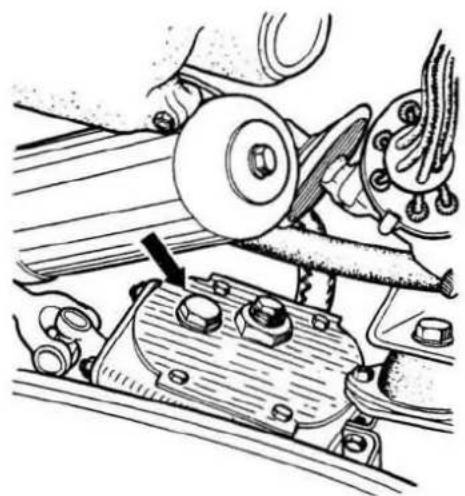
14 Remove the steering box filler plug as shown in FigRM.5 (do not confuse this plug with the rocker shaft adjustment screw) and fill the box with oil until no more will enter. Replace the plug.
15 Clean around the filler cap on the hydraulic reservoir for power assisted steering systems. Remove the cap by turning it anti-clockwise and top up as required using the correct grade of oil.
16 Adjust the handbrake cable in the manner described in Chapter 9.
17 The air cleaner of the oil bath type (where fitted) should be removed for cleaning but the periods at which this work is necessary will vary with the conditions under which the car is operated. For normal conditions, cleaning every 2500 miles is adequate but where the car is in frequent use in very dusty conditions it is advisable to clean at about 1000 mile intervals. To remove the air cleaner (Fig.RM 6), unscrew the wing nut and take off the top cover and then lift out the filler element and the oil base. Wash the element thoroughly in a bowl of clean paraffin and allow it to drain. Empty the oil from the oil base and clean out the sludge which will have collected in the bottom. Fill the base with engine oil to the level indicated by the arrow, make sure that the top cover gasket is in good condition and then reassemble the filter. There is no need to re-oil the filter element as this will be done automatically when the car is driven.
18 Where automatic transmission is fitted, check the level of the fluid and top up as required. The transmission filler/dipstick tube is located on the right hand side of the engine just forward of the bulkhead. When checking the fluid level make sure that the car is on level ground, apply the handbrake, start the engine and place the selector lever in "P". It is preferable to check the fluid level after a run when the transmission is hot, but in any event, run the engine until the transmission attains its normal running temperature. Remove the dipstick, wipe it dry and then replace it in the filler tube, ensure that it enters fully and then withdraw immediately and check. Add only sufficient fluid to bring the level to the FULL mark on the dipstick, DO NOT OVERFILL. If the fluid level is checked and topped up when cold, a false reading will be obtained and filling to the full mark will overfill the unit.
Every 5000/6000 miles (8000/10000 Km)
1 Carry out the 2500/3000 mile servicing.
2 If the top timing chain can be heard operating, adjust it in the manner described in Chapter 1 until there is slight flexibility on both outer sides of the chain below the camshaft sprockets ie it should not be dead tight.
3 Remove the bolts securing the petrol pipe banjo unions to the float chambers, remove the filters and clean them in petrol. (Fig RM.7).
4 Remove the fuel feed line filter bowl (FigRM.8) by undoing the nut at the bottom of the bowl and then swinging the clip outwards, do not drop the glass bowl. Clean away all sediment, examine the sealing washer and fit a new one if it is damaged.
5 Using a grease gun, grease the ball joints at the ends of the two steering tie rods (Fig.RM.9). During this operation, examine the rubber seals at the ends of the ball housings to see if they are displaced or perished, they should be replaced (see Chapter 11) if they are defective as this will allow dirt and water to enter the ball joint and cause rapid wear.
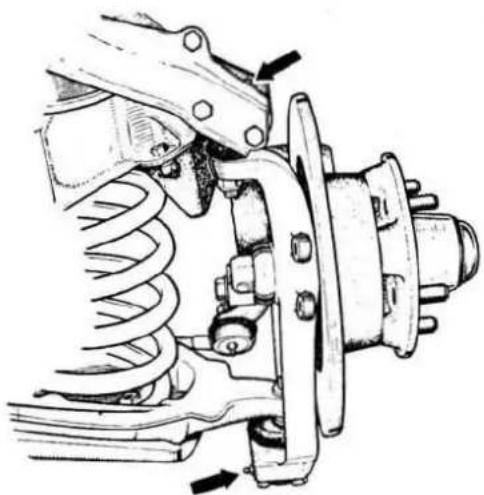
6 Lubricate the nipples to the wheel swivels as shown in
Fig RM 10. There is one nipple at the top and bottom swivel joints on each side of the car.
7 Take the car to a garage equipped to do the work and have the alignment of the front wheels checked, and adjusted if necessary, to the limits quoted in Chapter 11.
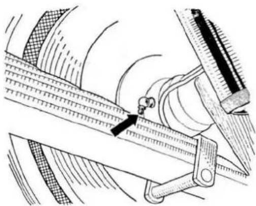
8 Grease the rear wheel bearings through the nipple provided (Fig.RM.11) at the ends of the rear axle tubes. Cease pumping in grease as soon as it comes out of the bleed hole opposite the nipple.
9 Lightly spray the rear spring leaves with penetrating oil but keep the oil away from the rubber mountings at the ends and the centre of each spring.
10 On cars fitted with drum brakes, remove the road wheels in turn, take off the brake drum and examine the linings. If the rivet heads are close to the face of the friction lining a new set of brake shoes should be fitted. This work is described in Chapter 9. To get the best results it is advisable to fit new shoes all round but at least also replace the shoes to the wheel on the opposite side of the car. Clean out any dust and dirt from the brake drums and reassemble.
11 Refer to Chapter 9 and follow the instructions for the removal of the brake friction pads fitted to disc brake models. The pads should be renewed when they have worn down to a thickness of 14'' (7 mm).
12 Remove the brake servo air cleaner which is attached to a rubber pipe on the right hand wing valance. Wash the cleaner in methylated spirits and then allow it to dry. After drying, lubricate the wire mesh with brake fluid and refit the cleaner.
13 Lubricate the door hinges sparingly using a grease gun applied to the grease nipple at each hinge. Wipe away any surplus grease.
14 Use an oil can to lubricate:-
Seat runners and adjusting mechanisms.
Handbrake ratchet.
Door locks.
Luggage boot hinges and lock.
Bonnet hinges and catches.
Windscreen wiper arms.
Accelerator linkage.
Petrol filler cover hinge.
Rear bearing of the dynamo (few drops only through hole marked "oil").
Every 10,000/12,000 miles (16,000/20,000 Km)
1 Complete the 5000/6000 mile servicing.
2 Renew the paper element air cleaner (if fitted), it is advisable, however, to change the element more frequently if the car is in frequent use in dusty conditions. The element is removed by rolling back the sealing rubber between the carburettor elbow and the air cleaner, slacken the two wing nuts which hold the air cleaner to the bracket on the cylinder head and then release the cleaner by pulling it towards the left side of the car. Release the two clips holding the end cover to the air cleaner and take off the end cover and the element. Now remove the wing nut, end cap and rubber ring securing the element to the end cover. Make sure that the two rubber sealing rings are in their correct positions when you refit the element.
3 Whilst you have the feed line filter bowl removed for cleaning, renew the sealing washers.
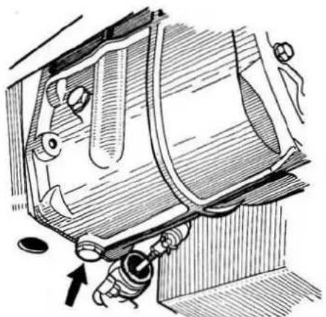
4 Drain the gearbox when warm by removing the plug shown in Fig.RM.12 and after all oil has drained away, replace the plug and then refill the box, with the recommended grade of oil, through the combined level and filler plug on the left hand side of the gearbox casing (the plug can be seen above that arrowed in Fig.RM 12). The level of oil should be to the bottom of the hole.
5 If an overdrive unit is fitted, this also should be drained as although the oil for the overdrive is common with that of the gearbox it is not drained when the gearbox is emptied. Remove the plug shown in Fig.RM 13 and allow the oil to drain into a container. Whilst the oil is draining, remove the filter and thoroughly clean it in petrol and allow to dry before refitting,

natural_image
Technical diagram of a mechanical assembly with pipes and components (no visible text or labels)RM1. The engine sump drain plug
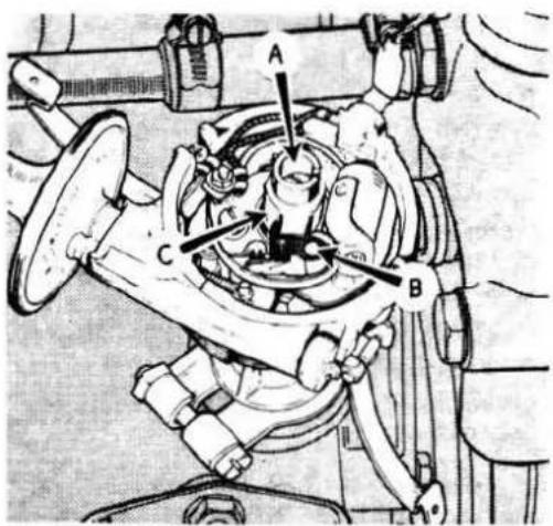
RM.2. Distributor lubrication points

natural_image
Mechanical assembly diagram showing a belt drive mechanism with pulleys and bolts (no text or labels)RM.3. Slacken dynamo mounting bolts to adjust fan belt tension

natural_image
Technical line drawing of a mechanical assembly with no visible text or symbolsRM.4. The rear axle filler/level plug
natural_image
Mechanical assembly diagram showing a wheel and gear assembly with no visible text or symbolsRM.5. The steering box filler plug

natural_image
Exploded view diagram of a mechanical device showing internal components like gears and housing (no text or labels)RM.6. The oil bath air cleaner
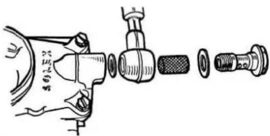
RM.7. The carburettor filter

natural_image
Mechanical assembly diagram showing linkage mechanism with no visible text or symbolsRM.9. Steering tie rod lubrication points (one side shown)
natural_image
Technical illustration of a mechanical assembly with no visible text or symbolsRM.11. Rear wheel bearing grease nipple

RM.8. THE FUEL FEED LINE FILTER
1 Retaining clip
2 Filter gauze
3 Sealing washer
4 Glass bowl
natural_image
Technical line drawing of a vehicle suspension system with springs and frame (no text or labels)RM.10. Wheel swivel lubrication points (one side shown)
natural_image
Technical line drawing of a mechanical assembly with no visible text or symbolsRM.12. The gearbox drain plug

natural_image
Technical line drawing of a mechanical device with no visible text or symbolsRM.13. The overdrive drain plug

natural_image
Technical line drawing of a mechanical assembly with no visible text or symbolsRM.14. The rear axle drain plug

natural_image
Technical line drawing of a mechanical assembly with no visible text or symbolsRM.15. The automatic transmission drain plug
the "A" Type Compact unit is provided with magnetic washers and these also must be thoroughly cleaned to remove any sign of metallic dust. The filter of the "A" Type unit is accessible through the drain plug hole and is secured by a central screw. The filter plug of the "A" Type Compact unit is located in the side of the overdrive unit. Maintain absolute cleanliness when refilling the gearbox of overdrive models as any dirt entering the system may seriously affect the operation of the overdrive. Recheck the level after the car has been run as a certain amount of lubricant will have been retained in the hydraulic system of the overdrive.
6 Drain the rear axle, after a run when the oil is hot, by removing the drain plug shown in Fig.RM.14. Refill the axle with the recommended grade of hypoid oil to the level of the bottom of the filler hole (see Fig.RM.4).
7 Refer to Chapter 11 and check the end float of the front and rear wheel bearings in the manner described. Grease the bearings after checking the end float, the rear hubs by means of the grease nipple provided on the rear axle tube but cease pumping in grease when it escapes from the bleed hole opposite to the nipple. There are no grease nipples to the front wheel bearings of cars fitted with drum type brakes; on these models the front wheel hub must be removed and then the taper roller bearing must be cleaned out and repacked with a recommended grade of high melting point grease. Do not pack the hub with grease but merely apply a coating to the inside of the hub between the outer races of the bearings and apply a light coat of grease to the stub axle shaft. Do not fill the hub end cap. The front wheel bearings of early model cars fitted with disc brakes are greased by means of a grease nipple (one per wheel) but to gain access to this you will have to remove the roadwheel (make sure that the car is firmly supported before you start work). Lubricate sparingly and cease pumping in grease when it escapes through the bleed hole in the end cap of the hub or, on cars with wire spoked wheels, when the grease can be seen to escape past the outer hub bearing. The foregoing also applies to late model cars except that in this case, access to the front wheel bearing grease nipple is obtained by merely removing the nave plate.
8 Remove the spark plugs and replace them with a new set of the correct type for the model details of which will be found under Specifications to Chapter 1 of this Manual.
9 Go over the car carefully looking for deterioration of rubber components such as radiator hoses, engine mountings etc. Look also for loosening of nuts and bolts especially those locked with spring or shakeproof washers.
10 Have head and fog lamp alignment checked and adjusted if necessary.
Every 21,000 miles (35,000 km)
1 Complete the 2500/3000 mile servicing.
2 On those cars fitted with automatic transmission, drain off the transmission fluid by removing the drain plug located in the bottom of the oil pan as illustrated in Fig.RM.15. Now remove the oil pan and wash it out thoroughly. The front and rear brake bands must now be adjusted and details of how to do this will be found in Chapter 6, however, as special tools are required to do this work properly you may consider it advisable to entrust the draining and adjustment of the system to a Jaguar dealer.
Every 24,000 miles (40,000 km)
1 Complete the 12,000 mile servicing.
On those cars fitted with power assisted steering, renew the paper filter element in the oil reservoir by removing the bolt securing the oil reservoir top cover and then lifting off the top cover and collecting the spring and retainer plate. Lift out the filter. When refitting the new filter make sure that it is located in the support plate at the bottom of the reservoir. Refit the cover and tighten the central bolt.
Chapter 1 Engine
Contents
| General description | ... | ... | ... | ... | ... | 1 |
| Major operations with engine in place | ... | ... | ... | ... | ... | 2 |
| Major operations with the engine removed | ... | ... | ... | ... | ... | 3 |
| Methods of engine removal | ... | ... | ... | ... | ... | 4 |
| Engine removal with gearbox - lifting upwards | ... | ... | ... | ... | ... | 5 |
| Engine removal less gearbox | ... | ... | ... | ... | ... | 6 |
| Engine removal with gearbox - from underside | ... | ... | ... | ... | ... | 7 |
| Separating the engine from the gearbox | ... | ... | ... | ... | ... | 8 |
| Separating the engine from the transmission unit (automatic) | 9 | |||||
| Removal and replacement of gearbox and clutch assemblywith engine installed | ... | ... | ... | ... | ... | 10 |
| Dismantling the engine - general | ... | ... | ... | ... | ... | 11 |
| Removing the ancillary engine components | ... | ... | ... | ... | ... | 12 |
| Cylinder head removal - engine on bench | ... | ... | ... | ... | ... | 13 |
| Cylinder head removal - engine in car | ... | ... | ... | ... | ... | 14 |
| Camshaft - removal | ... | ... | ... | ... | ... | 15 |
| Valve removal | ... | ... | ... | ... | ... | 16 |
| Valve and tappet guide removal | ... | ... | ... | ... | ... | 17 |
| Sump, piston, connecting rod and big end bearing - removal | 18 | |||||
| Timing gear - removal | ... | ... | ... | ... | ... | 19 |
| Gudgeon pin removal | ... | ... | ... | ... | ... | 20 |
| Piston ring - removal | ... | ... | ... | ... | ... | 21 |
| Oil pump assembly - removal | ... | ... | ... | ... | ... | 22 |
| Distributor drive - removal | ... | ... | ... | ... | ... | 23 |
| Crankshaft - removal | ... | ... | ... | ... | ... | 24 |
| Lubrication system - description. | ... | ... | ... | ... | ... | 25 |
| Oil filter - removal and replacement | ... | ... | ... | ... | ... | 26 |
| Engine examination and renovation - general | ... | ... | ... | ... | ... | 27 |
| Crankshaft - examination and renovation | ... | ... | ... | ... | ... | 28 |
| Crankshaft pulley and damper - examination and renovation | 29 | |||||
| Big end and main bearings - examination and renovation | 30 | |||||
| Flywheel - examination and renovation | ... | ... | ... | ... | ... | 31 |
| Cylinder block - examination and renovation | 32 | |||||
| Pistons and piston rings - general | ... | ... | ... | ... | ... | 33 |
| Piston, piston ring and gudgeon pin - examination andrenovation | 34 | |||||
| Connecting rods - examination and renovation | 35 | |||||
| Camshaft and camshaft bearings - examination and renovation | 36 | |||||
| Valves and seats - examination and renovation | 37 | |||||
| Inlet valve oil seals - general | ... | ... | ... | ... | ... | 38 |
| Valve springs - examination and test | 39 | |||||
| Tappets and valve adjusting pads - examination and renovation | 40 | |||||
| Cylinder head and bore - decarbonisation, examination and | ||||||
| renovation | ... | ... | ... | ... | ... | ... | 41 |
| Compression pressures - general | ... | ... | ... | ... | ... | ... | 42 |
| Timing gear and chain - examination and renovation | ... | ... | ... | ... | ... | ... | 43 |
| Oil pump - examination and renovation | ... | ... | ... | ... | ... | ... | 44 |
| Bottom chain tensioner - examination and renovation | ... | ... | ... | ... | ... | ... | 45 |
| Automatic fan belt tensioner - examination and renovation | ... | ... | ... | ... | ... | ... | 46 |
| Engine stabiliser - examination and renovation | ... | ... | ... | ... | ... | ... | 47 |
| Engine mountings - general | ... | ... | ... | ... | ... | ... | 48 |
| Engine mountings | ... | ... | ... | ... | ... | ... | 49 |
| Air cleaners - general | ... | ... | ... | ... | ... | ... | 50 |
| Air cleaners - maintenance | ... | ... | ... | ... | ... | ... | 51 |
| Engine reassembly - general | ... | ... | ... | ... | ... | ... | 52 |
| Crankshaft - replacement | ... | ... | ... | ... | ... | ... | 53 |
| Piston and connecting rod - reassembly | ... | ... | ... | ... | ... | ... | 54 |
| Piston ring - replacement | ... | ... | ... | ... | ... | ... | 55 |
| Piston - replacement | ... | ... | ... | ... | ... | ... | 56 |
| Connecting rod to crankshaft - reassembly | ... | ... | ... | ... | ... | ... | 57 |
| Crankshaft gear and sprocket - reassembly | ... | ... | ... | ... | ... | ... | 58 |
| Distributor and oil pump drive gear - reassembly | ... | ... | ... | ... | ... | ... | 59 |
| Oil pump and pipes - reassembly | ... | ... | ... | ... | ... | ... | 60 |
| Timing gear - assembly | ... | ... | ... | ... | ... | ... | 61 |
| Timing gear - reassembly to engine | ... | ... | ... | ... | ... | ... | 62 |
| Timing chain tensioner - reassembly | ... | ... | ... | ... | ... | ... | 63 |
| Timing cover - refitting | ... | ... | ... | ... | ... | ... | 64 |
| Oil sump - refitting | ... | ... | ... | ... | ... | ... | 65 |
| Flywheel and clutch - refitting | ... | ... | ... | ... | ... | ... | 66 |
| Oil filter - refitting | ... | ... | ... | ... | ... | ... | 67 |
| Crankshaft damper and pulley - refitting | ... | ... | ... | ... | ... | ... | 68 |
| Distributor - refitting | ... | ... | ... | ... | ... | ... | 69 |
| Cylinder head - reassembly | ... | ... | ... | ... | ... | ... | 70 |
| Valve clearance adjustment | ... | ... | ... | ... | ... | ... | 71 |
| Cylinder head - refitting | ... | ... | ... | ... | ... | ... | 72 |
| Valve timing | ... | ... | ... | ... | ... | ... | 73 |
| Inlet manifold - refitting | ... | ... | ... | ... | ... | ... | 74 |
| Cylinder head oil feed pipe - refitting | ... | ... | ... | ... | ... | ... | 75 |
| Water pump - refitting | ... | ... | ... | ... | ... | ... | 76 |
| Engine breather assembly - refitting | ... | ... | ... | ... | ... | ... | 77 |
| Gearbox - refitting | ... | ... | ... | ... | ... | ... | 78 |
| Final assembly | ... | ... | ... | ... | ... | ... | 79 |
| Engine replacement | ... | ... | ... | ... | ... | ... | 80 |
| Engine initial start up after overhaul and major repair | ... | ... | ... | ... | ... | ... | 81 |
| Fault diagnosis | ... | ... | ... | ... | ... | ... | 82 |
Specifications
| Number of cylinders | 2.4 | 3.4 | 3.8 | |||||||
| 6 | 6 | 6 | ||||||||
| Bore (INS) | ... | ... | ... | ... | ... | ... | ... | 3.2677 | 3.2677 | 3.425 |
| (MM) | ... | ... | ... | ... | ... | ... | ... | 83 | 83 | 87 |
| Stroke (INS) | ... | ... | ... | ... | ... | ... | ... | 3.0118 | 4.1732 | 4.1732 |
| (MM) | ... | ... | ... | ... | ... | ... | ... | 76.5 | 106 | 106 |
Chapter 1/Engine
| Capacity (CC) ... ... ... ... ... ... ... ... | 2483 | 3442 | 3781 |
| Firing order ... ... ... ... ... ... ... ... | 153624 | ||
| Valve operation ... ... ... ... ... ... ... ... ... | Twin overhead camshafts | ||
| Camshaft | |||
| Number of journals ... ... ... ... ... ... ... ... | 4 | 4 | 4 |
| Journal diameter (IMS) ... ... ... ... ... ... ... | 1.00 - 0.005 (25.4 mm - 0.013- 0.001 | -0.025) | |
| Type of bearing ... ... ... ... ... ... ... ... | White metal - steel backed | ||
| Number of bearings ... ... ... ... ... ... ... ... | Four per shaft (eight half bearings) | ||
| Diameter clearance ... ... ... ... ... ... ... ... | 0.0005 to 0.002 in (0.013 to 0.05 mm) | ||
| Thrust taken ... ... ... ... ... ... ... ... | Front end | ||
| Permissible end float ... ... ... ... ... ... ... | 0.0045 to 0.008 in (0.11 to 0.20 mm) | ||
| Tightening torque - bearing Mk I ... ... ... ... ... | 15 lb f ft | ||
| Tightening torque - cap nuts Mk 2 ... ... ... ... | 9 lbs f ft | ||
| Connecting rods | |||
| Length - centre to centre (IMS) ... ... ... ... ... | 5.625 | 7.75 | 7.75 |
| (CM) ... ... ... ... ... | 13.28 | 19.68 | 19.68 |
| Crankpin bearing type: Early cars ... ... ... ... | White metal steel backed shell | ||
| Later cars ... ... ... ... | Lead bronze steel backed shell - lead indium coated | ||
| Crankpin bearing bore: (IMS) ... ... ... ... ... | 2.233 - 2.2335 | ||
| (MM) ... ... ... ... ... | 56.72 - 56.73 | ||
| Big end width ... ... ... ... ... ... | 2.4 | 3.4 | 3.8 |
| 1.1875 in - 0.006 (30.16 mm - 0.15- 0.008) | |||
| Big end - diameter clearance ... ... ... ... ... | White metal 0.001 to 0.0025 in (0.25 to 0.06 mm) | ||
| Lead indium 0.0023 to 0.0039 in (0.06 to 0.10 mm) | |||
| Big end - side clearance ... ... ... ... ... | 0.0058 to 0.0087 in (0.15 to 0.22 mm) | ||
| Small end bush - type ... ... ... ... ... | Phosphor bronze - steel backed | ||
| Small end - width ... ... ... ... ... | 1.0781 in (27.4 mm) | ||
| Small end bush - bore ... ... ... ... ... | 0.875 in + 0.0002 (22.22 mm + 0.005,- 0.0000 | -0.000 | -0.000 |
| Tightening torque - con rod bolts ... ... ... ... | 37 lb f ft | ||
| Crankshaft | |||
| Number of main bearings ... ... ... ... ... | Seven | ||
| Main bearing - type ... ... ... ... ... | White metal steel backed shell | ||
| Journal diameter ... ... ... ... ... | Front, centre, rear 2.750 to 2.7505 in (69.85 to 69.86 mm)Intermediate 2.4795 to 2.750 in (69.84 to 69.85 mm) | ||
| Journal length | |||
| Front ... ... ... ... ... ... | 1.6875 ± 0.005 in (42.86 ± 0.13 mm) | ||
| Centre ... ... ... ... ... ... | 1.75 + 0.0005 in (44.45 + 0.013- 0.001) | ||
| Rear ... ... ... ... ... ... | 1.875 in (47.63 mm) | ||
| Intermediate ... ... ... ... ... ... | 1.2188 ± 0.002 in (30.96 ± 0.05 mm) | ||
| Thrust taken ... ... ... ... ... ... | Centre bearing thrust washers | ||
| Thrust washer - thickness ... ... ... ... ... | 0.092 ± 0.001 in and 0.096 ± 0.001 in(2.33 ± 0.025 mm and 2.43 ± 0.025 mm) | ||
| Engine clearance ... ... ... ... ... ... | 0.004 to 0.006 in (0.10 to 0.15 mm) | ||
| Main bearing - length | |||
| Front, centre, rear ... ... ... ... ... | 1.5 ± 0.005 in (38.1 ± 0.13 mm) | ||
| Intermediate ... ... ... ... ... ... | 1 ± 0.005 in (25.4 ± 0.13 mm) | ||
| Diameter clearance ... ... ... ... ... ... | 0.0015 to 0.003 in (0.04 to 0.08 mm) | ||
| Crankpin diameter ... ... ... ... ... | 2.086 + 0.0006 in (52.98 + 0.015 mm)- 0.0000 | -0.000 | -0.000 |
| Length ... ... ... ... ... ... | 1.1875 + 0.0007 in (30.16 + 0.018 mm)- 0.0002 | -0.006 | -0.006 |
| Regrind undersize ... ... ... ... ... | 0.010, 0.020, 0.030, 0.040 in (0.25, 0.51, 0.76 and 1.02 mm) | ||
| Minimum diameter for regrind ... ... ... ... | - 0.040 in (1.02 mm) | ||
| Tightening torque - main bearing bolts ... ... ... | 83 lb f ft | ||
| Cylinder block | |||
| Material - 2.4 and 3.4 litre ... ... ... ... | Chromium iron | ||
| 240 and 340 | |||
| 3.8 litre ... ... ... ... ... | "Brivadium" dry liners | ||
| Cylinder bores - nominal | |||
| 2.4 and 3.4 litre ... ... ... ... | 3.2677 + 0.0005 - 0.00025 in (83 + 0.0127 - 0.0064 mm) | ||
| 240 and 340 | |||
| 3.8 litre ... ... ... ... ... | 3.4252 + 0.0005 - 0.00025 in (87 + 0.0127 - 0.0064 mm)+ 0.030 in (0.76 mm) | ||
| Maximum rebore size ... ... ... ... | 3.391 to 3.392 in (86.13 to 86.16 mm) | ||
| Bore size for fitting liners | |||
| 2.4 and 3.4 litre ... ... ... ... | 3.391 to 3.392 in (86.13 to 86.16 mm) | ||

natural_image
Technical line drawing of a mechanical engine assembly (no text or labels)Fig.1.1. Cross sectional view of 2.4 litre engine
240 and 340
Outside diameter of liner
2.4 and 3.4 litre ...
240 and 340
Overall length of liner
Outside diameter of lead-in
Size of bore honed after assembly in cylinder block - Nominal
Main line bore for main bearings ... ... ... ...
Cylinder head
Valve throat diameter
Inlet - 2.4 litre Mk 1 ... ... ... ... ...
2.4 Mk 1, 3.4 and 3.8 litre ... ... ...
Exhaust - 2.4 litre Mk 1
2.4 Mk 2, 3.4 and 3.8 litre ... ... ...
3.561 to 3.562 in (90.45 to 90.49 mm)
3.3945 to 3.3955 in (86.22 to 86.25 mm)
3.563 to 3.566 in (90.45 to 90.58 mm)
0.0025 to 0.0045 in (0.06 to 0.11 mm)
5.9375 in (15.08 cm)
6.9688 in (17.7 cm)
3.389 to 3.391 in (86.08 to 86.13 mm)
3.558 to 3.560 in (90.37 to 90.42 mm)
3.2677 in (83 mm)
3.4252 in (87 mm)
2.9165 + 0.0005 in (74.08 + 0.013 mm)
-0.0000 -0.000
Standard
"B" type
Aluminium alloy
30 degrees
45 degrees
All models 45 degrees
1.375 in (34.9 mm)
1.5 in (38.1 mm)
1.25 in (31.75 mm)
1.375 in (34.9 mm)
Chapter 1/Engine
| Tightening torque - cylinder head nuts ... ... ... | 54 lb f ft | |||||||||||||||||||||||||||||||||||||||||||||||||||||||||||||||||||||||||||||||||||||||||||||||||||||||||||||||||||||||||||||||||||||||||||||||||||||||||||
| Firing order ... ... ... ... ... ... ... ... | 1 5 3 6 2 4No 1 cylinder being at rear of engine unit. | 54 lb f ft | ||||||||||||||||||||||||||||||||||||||||||||||||||||||||||||||||||||||||||||||||||||||||||||||||||||||||||||||||||||||||||||||||||||||||||||||||||||||||||
| Gudgeon pinType ... ... ... ... ... ... ... ... ... | Fully floating2.840 to 2.845 in (72.14 to 72.26 mm)0.625 in (15.87 mm)0.8750 to 0.8752 in (22.22 to 22.23 mm) | |||||||||||||||||||||||||||||||||||||||||||||||||||||||||||||||||||||||||||||||||||||||||||||||||||||||||||||||||||||||||||||||||||||||||||||||||||||||||||
| Length diameter ... ... ... ... ... ... ... ... | 0.625 in (15.87 mm)0.8750 to 0.8752 in (22.22 to 22.23 mm) | |||||||||||||||||||||||||||||||||||||||||||||||||||||||||||||||||||||||||||||||||||||||||||||||||||||||||||||||||||||||||||||||||||||||||||||||||||||||||||
| Inside diameter ... ... ... ... ... ... ... ... | 40 lb per sq in at 3000 rpmEccentric rotor0.010 in maximum (0.25 mm)0.004 in maximum (0.010 mm)0.010 in maximum (0.25 mm) |
| Number of pitches - top chain ... ... ... ... | 100 | |
| bottom chain ... ... ... ... | ||
| 2.4 litre Mk 1 and 2 ... ... ... | 68 | |
| 3.4 and 3.8 litre ... ... ... ... | 82 | |
| 240 | ||
| 340 | ||
| Crankshaft sprocket - teeth ... ... ... ... | 21 | |
| Intermediate sprocket, outer - teeth ... ... ... ... | 28 | |
| Intermediate sprocket, inner - teeth ... ... ... ... | 20 | |
| Camshaft sprocket - teeth ... ... ... ... | 30 | |
| Idler sprocket ... ... ... ... ... | 21 | |
| Valve timing | 2.4 litres and 240 3.4 litre, 3.8 litre and 340 | |
| Inlet valve opens ... ... ... ... ... ... | 10^ B.T.D.C | 15^ B.T.D.C |
| Inlet valve closes ... ... ... ... ... ... | 50^ A.B.D.C | 57^ A.B.D.C |
| Exhaust valve opens ... ... ... ... ... ... | 57^ B.B.D.C | 57^ B.B.D.C |
| Exhaust valve closes ... ... ... ... ... ... | 15^ A.T.D.C | 15^ A.T.D.C(with valve clearances set at 0.010 in (0.25 mm)) |
| Valves and valve springs | ||
| Valves - Material, Inlet ... ... ... ... ... | Silicon chrome steel | |
| Exhaust | ||
| Mk 1 models ... ... ... | Austenitic steel | |
| Mk 2, 240 and 340 models ... | 21-4-NS | |
| Valve head diameter, inlet ... ... ... ... ... | 1.75 ± 0.002 in ( 44.45 ± 0.05 mm) | |
| exhaust ... ... ... ... ... | 1.625 ± 0.002 in ( 41.27 ± 0.05 mm) | |
| Valve stem diameter, inlet and exhaust ... ... ... ... | 0.3125 - 0.0025 in ( 7.95 - 0.06 mm) -0.0035 in -0.09 mm) | |
| Valve lift - 2.4 litre and 240 ... ... ... ... | 0.3125 in (7.95 mm) | |
| 3.4, 340 and 3.8 litre ... ... ... ... | 0.375 in (9.5 mm) | |
| Valve clearance - Inlet ... ... ... ... ... | 0.004 in (0.10 mm) | |
| Exhaust ... ... ... ... ... | 0.006 in (0.15 mm) | |
| Valve seat angle - Inlet | ||
| 2.4 litre Mk 1 ... ... ... | 30^ | |
| All other models ... ... ... | 45^ | |
| Exhaust ... ... ... ... ... | 45^ | |
| Valve spring - free length | ||
| Inner ... ... ... ... ... | 1.656 in (42.06 mm) | |
| Outer ... ... ... ... ... | 1.9375 in (49.2 mm) | |
| Valve spring fitted length | ||
| Inner ... ... ... ... ... | 1.2188 in (30.96 mm) | |
| Outer ... ... ... ... ... | 1.3125 in (33.34 mm) | |
| Valve spring - fitted load | ||
| Inner ... ... ... ... ... | 30.33 lbs (13.76 kg) | |
| Outer ... ... ... ... ... | 48.375 lbs (21.94 kg) | |
| Valve spring - Solid length (max) | ||
| Inner ... ... ... ... ... | 0.810 in (20.57 mm) | |
| Outer ... ... ... ... ... | 0.880 in (22.35 mm) | |
| Number of free coils | ||
| Inner ... ... ... ... ... | 6 | |
| Outer ... ... ... ... ... | 5 | |
| Diameter of wire - Inner ... ... ... ... ... | 12 SWG | |
| Outer ... ... ... ... ... | 10 SWG | |
Valve guide and valve seat insert
| Valve guides - material | ... | ... | ... | ... | ... |
| Valve guide - length, inlet | ... | ... | ... | ... | ... |
| exhaust | ... | ... | ... | ... | ... |
| Valve guide - inside diameter | |||||
| inlet | ... | ... | ... | ... | ... |
| exhaust | ... | ... | ... | ... | ... |
| Interference fit in head | ... | ... | ... | ... | ... |
| Valve seat inserts - material inside diameter, inlet | ... | ... | ... | ... | ... |
| 2.4 litre Mk 1 | ... | ... | ... | ... | |
| All other models exhaust | ... | ... | ... | ... | |
| 2.4 litre Mk 1 | ... | ... | ... | ... | |
| All other models interference shrink fit in head | ... | ... | ... | ... | |
Cast iron
| 1.813 in (46.04 mm) | |
| 1.938 in (49.21 mm) | |
| 0.3125 - 0.0005 in (7.94 - 0.013 mm) | |
| 0.3125 ± 0.0005 in (7.94 ± 0.01 mm) | |
| 0.0005 to 0.0022 in (0.013 to 0.055 mm) | |
| Cast iron (centrifugally cast) | |
| + 0.003 | + 0.076 |
| 1.375 - 0.001 in (34.92 - 0.025 mm) | |
| + 0.003 | + 0.076 |
| 1.50 - 0.001 in (38.1 - 0.025 mm) | |
| + 0.003 | + 0.76 |
| 1.25 - 0.001 in (31.75 - 0.025 mm) | |
| 1.379 to 1.383 in (35.03 to 35.13 mm) | |
| 0.003 in (0.076 mm) | |

natural_image
Technical line drawing of an internal combustion engine assembly (no text or labels)Fig.1.2. Longitudinal section view of 2.4 litre engine
1 General description
The engines fitted to the models covered by this manual are identical except in regard to length of stroke and cubic capacity.
They are based upon the original twin overhead camshaft XK power unit which had a cubic capacity of 3442 cc. The bore and stroke of that engine was retained but following development and modification it became the production 3.4 litre engine.
The 2.4 litre is a short stroke version of this engine, the stroke having been reduced from 4.1732 in (106 mm) to 3.0018 in (76.5 mm). The 3.8 litre engine is a further variation having the same stroke as the 3.4 litre but the cylinder bore was increased from 83 mm to 87 mm. The 3.8 litre engines was not available in Mk.1. cars but the 2.4 litre engine is fitted to 240 models and the 3.4 litre to 340 models.
The six-cylinder in-line engines are of unit constructions, are water cooled and are provided with two overhead camshafts operating the inlet and exhaust valves respectively. As indicated later in this chapter, there is no provision for routine adjustment of valve clearances. Valve timing 2.4 litre engines differs from that of 3.4 and 3.8 litre engines which are the same. The camshafts are roller chain driven and the drive is provided with chain tensioners.
The cylinder block is cast integral with the crankcase. The cylinder head is detachable and is made of aluminium alloy with machined hemispherical combustion chambers. The valve seat inserts and valve guides are of cast iron and are shrunk into the cylinder head.
The crankshaft is counterbalanced and is provided with seven plain shell bearings all of which are pressure lubricated. Axial thrust is taken at the centre bearing position. A torsional vibration damper (except early 2.4 litre engines) is fitted externally to the front of the crankshaft. The generator and the water pump impeller, which is of centrifugal type, are driven by a single belt from a pulley which is immediately forward of the crankshaft vibration damper.
The oil pump is driven from the front end of the crankshaft and is located inside the sump drawing oil through an internal pipe from the rear. Pressurised oil is fully filtered before being fed to the engine, it passes through an external oil filter of the fullflow type which incorporates a balance valve and a relief valve from which excess oil is returned to the sump. Oil is fed to the camshafts via the main oil feed gallery in the cylinder block and an external pipe at the rear of the engine.
Plain shell big-end bearings are provided for the connecting rods and phosphor bronze bushes for the gudgeon pins which are pressure oil-fed through longitudinal drillings up the connecting rod. The pistons are semi-split skirt type and are made from aluminium alloy. Different pistons can be used to give compression ratios of 7:1 and 8:1 in 2.4 litre engines and 7:1, 8:1 and 9:1 in 3.4 and 3.8 litre engines. Despite similar diameters the pistons for the 2.4 and 3.4 litre engines are not interchangeable. Gudgeon pins of the fully floating type are used.
All engines are fitted with twin carburettors, those on the 2.4 Mk.1 and 2 cars are Solex downdraught type whilst SU side-draught are fitted to all other models. An air cleaner, which also provides air intake silencing is fitted. It must be noted that ignition timing is not identical and is dependent on the type of air cleaner fitted, engine capacity and compression ratio; full information of the variations are given later in this Chapter. Ignition is by coil and the distributor, which is driven by the same crankshaft gear as the oil pump, is an automatic advance/retard unit.
The engine is supported on two rubber mountings at the front; engines with manual gearboxes utilise a spring type mounting at the rear whilst rubber mountings are provided for those engines fitted with automatic gearboxes. All engines have, in addition, a stabiliser which is located immediately behind the cylinder block.
Twin exhaust manifolds, each serving three cylinders, connect with a branched downpipe and single silencer and tailpipe system in the case of 2.4 litre engines but 3.4 and 3.8 litre engines are provided with two downpipes and twin silencers and tailpipes.
2 Major operations with engine in place
The following major operations can be carried out with the engine in place in the car:-
1 Removal and replacement of the cylinder head assembly.
2 Removal and replacement of the sump.
3 Removal and replacement of the big end bearings.
4 Removal and replacement of the pistons and connecting rods.
5 Removal and replacement of the camshafts.
6 Removal and replacement of the oil pump.
7 Removal and replacement of the timing gear.
8 Removal and replacement of the clutch driven plate.
3 Major operations with the engine removed
The following major operations must be carried out with the engine removed from the car and on a bench or on the floor:-
1 Removal and replacement of the main bearings.
2 Removal and replacement of the crankshaft.
4 Methods of engine removal
The engine and gearbox assembly weighs approximately 8 cwt, it is essential, therefore, that the lifting tackle and ancillary equipment being used to remove, and to replace, the engine are in good condition and are suitable for the task. The engine can be removed by either lifting it, with gearbox attached, upwards out of the engine compartment or by lowering the assembly below the car. The following factors must be taken into account when deciding which method to use:
1 The lifting tackle used must be capable of lifting the engine about three feet upwards out of the car.
2 To drop the engine downwards out of the car:-
a) The front suspension must be removed.
b) A pit, deep enough to allow working under the car and wide enough to allow an assistant to remain in the pit, in safety, to guide the engine whilst it is being lowered, must be available.
5 Engine removal with gearbox - lifting upwards
1 Disconnect and remove the battery.
2 Drain coolant from the system in the manner described in Chapter 2.
3 Remove the sump and gearbox drain plugs and drain the oil from these items.
4 Remove the front seat squabs.
5 Undo and remove captive nut at the front, and the screw at the rear, of each seat slide and remove the front seats.
6 Remove the gear lever knob.
7 Remove the serrated nut at the rear of the heater cover and the screws securing it to the front console and lift out the heater cover.
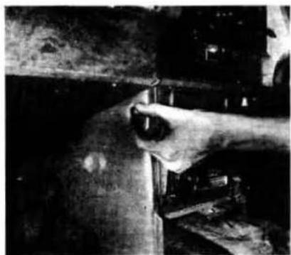
8 Remove the screws holding the gear lever grommet securing ring and lift out the rubber grommet and the ring.
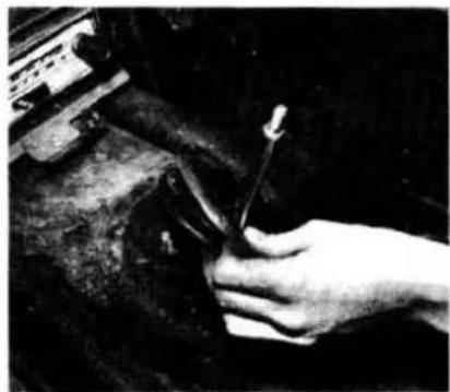
9 Remove the console side covers by undoing the chrome plated nut.
10 Remove the front console panel and heater controls by undoing the securing screws at the top of the panel and one at the base. Move the panel to one side out of the way; there is no need to disconnect the heater control cables.
11 Disconnect the air distribution pipes at the front connection and move them back out of the way.
12 Remove, as carefully as possible, the sound proofing felt stuck to the gearbox dome cover.
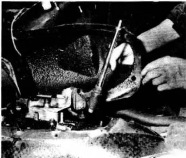
13 Remove the eleven screws securing the dome cover to the floor of the car and lift off the dome cover.
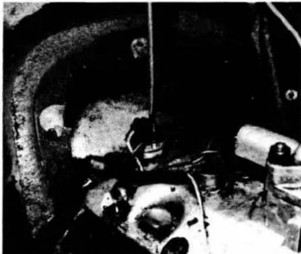
14 The top of the gearbox is now exposed and to the front of the gear lever remote control assembly will be seen the overdrive and reverse switches. Disconnect the leads to the switches.
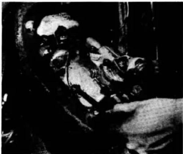
15 When lifting out the engine the gear lever tends to catch on the underside of the body of the car so, although not essential, it may be found advantageous at this point to remove the gear lever remote control assembly. Undo the four retaining nuts and lift out the assembly.
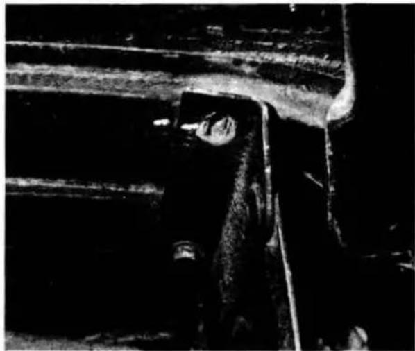
16 Mark the position of the hinge brackets of the bonnet to facilitate refitting.
17 With the help of an assistant take the weight of the bonnet. Remove the two set bolts securing the bonnet to each hinge, carefully lift the bonnet towards the front of the car and store in a safe place where it will not be scratched.
18 Undo the butterfly nut to the centre bolt of the air cleaner and lift out the air cleaner.
19 Undo the two bolts securing the air intake pipe to the carburettors and remove the pipe.
20 Remove the engine breather pipe by disconnecting the clip securing the flexible pipe to the breather housing at the front of the cylinder head.
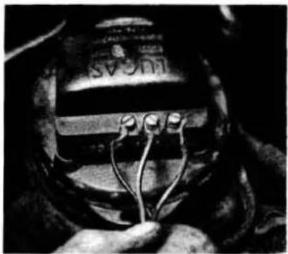
21 Disconnect the electrical leads and the plastic outlet tube to the windscreen washer bottle and remove the bottle (take note of the location of the leads for correct reassembly).
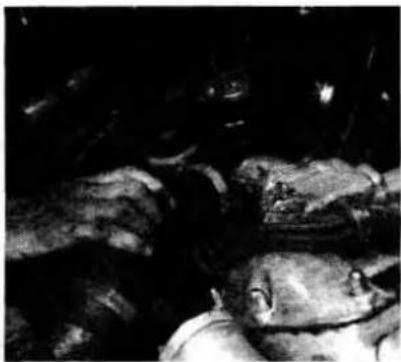
22 Undo the clips securing the top and bottom water hoses to the radiator. Remove the hoses.
23 Remove the radiator cowl (if fitted) and the radiator in the manner described in Chapter 2.
24 Remove the dynamo connections. Note that the brown/yellow wire is connected to the large terminal as is the radio suppressor (if fitted). Remove the two mounting bolts and the adjusting bolt; tilt the dynamo to slacken the fan belt, disengage the fan belt and lift out the dynamo.
25 Remove the nuts securing the exhaust manifolds to the cylinder head. Pull the manifolds outwards, secure them to take their weight and to keep them out of the way.
26 Disconnect the two clips securing the heater pipes at the rear of the engine and remove the two pipes.
27 Detach the leads from the tags on the revolution counter AC generator at the rear of the right hand camshaft cover.
28 Disconnect the clutch fluid pipe at the bracket at the rear of the cylinder head.
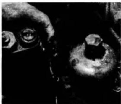
29 Disconnect the leads to the auxiliary starting carburettor.
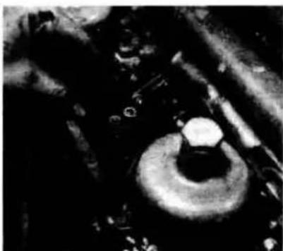
30 Remove the cover on the auxiliary starting carburettor.
31 Disconnect the fuel pipes at the float chambers by removing the banjo bolts. Note the fibre sealing washers.
32 Disconnect the fuel feed pipe at the fuel filter and remove it.
33 Remove the split pin, plain and spring washers from the connecting link pivot pin located on the manifold between the front and rear carburettors and disconnect the throttle link rod joint from the ball on the bell crank lever.
34 Remove the clip attaching the overflow pipes from the float chambers to the oil filter mounting screw and disconnect the union connecting the starter pipe to the auxiliary starting carburettor.
35 Remove the nuts and washers securing each carburettor to the inlet manifold and remove the carburettors. Note: The carburettors of the 2.4 litre engine need not be removed unless so desired.
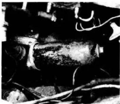
36 Remove the throttle support linkage and disconnect the throttle return spring at the oil filter.
37 Disconnect the leads from the oil pressure transmitter at the oil filter.
38 Detach the flexible rubber hose (brake servo) from the rigid pipe below the inlet manifold adjacent to the ignition distributor vacuum unit.
39 Disconnect the cable to the starter motor.
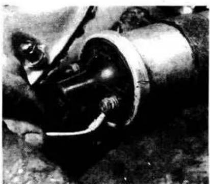
40 Detach the H.T. lead connections at the spark plugs. Remove the clip securing the plug lead harness. Disconnect the lead to the coil, unclip the distributor head and remove the head and also the rotor.
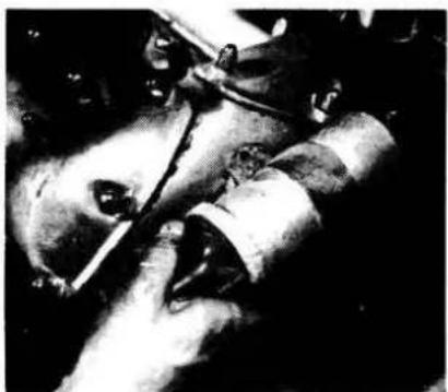
41 Remove the leads to the coil. Undo the two nuts and bolts securing the coil and remove the coil.
42 Remove the lead from the head of the temperature gauge indicator unit. This unit is located beneath or in the side of the water outlet pipe for the 2.4 litre or 3.4 and 3.8 litre cars
respectively.
43 Disconnect the earth connection to the gearbox at the bulkhead at the rear left hand side of the engine.
44 Remove the power assisted steering reservoir (when fitted) but first remove the pump inlet hose from beneath the reservoir and allow the oil to drain into a container.
45 Refer to Chapter 2 and remove the cooling fan.
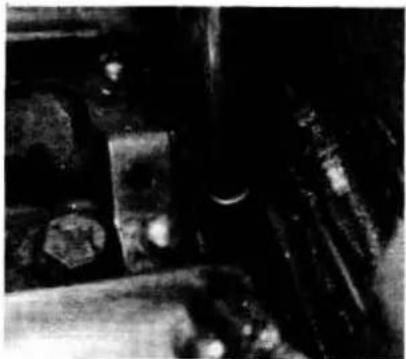
46 Remove the locknut and washer from the engine stabiliser at the rear of the cylinder block.
47 Disconnect the speedometer drive from the rear of the gearbox.
48 Undo the nuts securing the clutch master cylinder to the gearbox, pull it away from the box and away from the operating plunger.
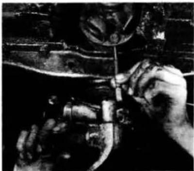
49 Mark the relative position of the propeller shaft and the gearbox flange so that they may be refitted in their original position. This is important otherwise vibration may be experienced.
50 Chock one rear wheel and jack up the other so that the propeller shaft can be rotated.
51 Remove the split pins, nuts and washers (or self locking nuts) to the bolts securing the shaft to the gearbox flange. For this operation it will either be necessary to chock the raised wheel or to hold the propeller shaft from turning by inserting a screwdriver between the shaft and the universal joint.
52 Seperate the shaft from the gearbox flange.
53 Sling the engine to take the weight off the mountings. A special lifting plate, Churchill Tool No. J.8. (see Fig.1.3) can be obtained for slinging the engine. Use of the tool requires the removal of cylinder head nuts No's 3,6, 8 and 9 and these can be identified by reference to Fig.1.8. The tool fits on those cylinder head studs and is held in position by the nuts, this is illustrated in Fig.1.4 which shows slinging of the engine less gearbox. As an alternative to the tool, make up two pieces of 2" or 3" angle iron about two inches wide and drill and fit to cylinder head studs No's 3 and 6. The upper flange should be
drilled to take the point of lift immediately above those studs.
54 Remove the bolt securing the engine to each front mounting. 55 As a safety measure and to hold the engine steady, support the gearbox on a jack.
56 Place a large washer over the spigot protruding from the centre of the rear mounting and insert a 1/8" diameter rod through the hole in the spigot. This will hold the mounting spring compressed when the mounting is removed from the body (Fig 1.5).
57 Remove the bolts and packing washers from the rear engine support bracket taking note of the number and position of the various packing washers fitted between the bracket and the body floor.
58 Lower the jack slightly to facilitate the removal of the nut and shakeproof washers securing the mounting to the bracket attached to the gearbox.
59 Lower and remove the jack but have an assistant watching the engine in the engine bay because as the jack is lowered so will the engine take up a hanging attitude, with gearbox down. 60 Make a final check that all connections between the engine/gearbox and body have been disconnected.
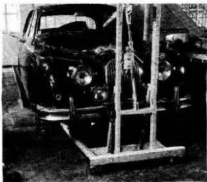
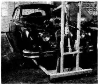
61 Commence lifting the engine checking continually that the gearbox is not fouling underneath the body.
62 When the sump is clear of the radiator grille, start inching the engine forwards or moving the car rearwards depending on the method of working.
63 Carry on lifting and moving the engine away from the car until the sump is clear of the front of the car, by this time the gearbox should be clear of the body and it should be possible to lift on the gearbox and to swing the engine clear of the car.
64 The engine may now be lowered on to a prepared stand or on to supports on the bench, or on the floor, so positioned that its weight is evenly distributed.
65 To complete the job, collect any loose nuts and bolts and tools from the engine compartment and the floor and place them where they will not be lost.

natural_image
Black-and-white photo of a person handling a large wooden object on a workbench, with no visible text or symbols.5.7. Remove heater cover
natural_image
Close-up of a hand using a tool on a wooden surface, no visible text or symbols5.8. Remove gear lever grommet and ring
natural_image
Close-up of a hand using a tool to adjust or install a mechanical component (no visible text or symbols)5.9. Remove console side covers

natural_image
Close-up of hands holding a vintage electronic device with a button (no visible text or symbols)5.10. Remove front console panel

natural_image
Close-up of a hand holding a wooden book with visible spine and spout (no text or symbols)5.11. Disconnect air distribution pipes

natural_image
Black-and-white photo of hands handling a large, textured object (no visible text or symbols)5.12. Remove sound-proofing
natural_image
Close-up of hands operating a mechanical component with tools and components (no visible text or symbols)5.13. Remove gearbox dome cover
natural_image
Close-up of mechanical components and wiring (no visible text or symbols)5.14. The overdrive and reverse switches
natural_image
Black-and-white photo of a person interacting with a device, possibly a robotic arm or device (no visible text or symbols)5.15. Remove gear lever remote control assembly
natural_image
Close-up of a mechanical component with a central hole and textured surface (no visible text or symbols)5.16. Mark position of bonnet hinges

natural_image
Black-and-white photo of a car engine bay with open hood, no visible text or symbols5.17. Lift off bonnet

natural_image
Close-up of a mechanical component with curved surfaces and a small circular feature, no visible text or symbols.5.18. Remove air cleaner

natural_image
Close-up of mechanical components or machinery with no visible text or symbols5.19. Remove air intake pipe
natural_image
Close-up of a mechanical component with wires and a label 'SVCM' (no readable text or symbols beyond the label)5.21. Disconnect leads to windscreen washer bottle (later models have two leads)
natural_image
Black-and-white photo of a person lying down under dark lighting, no visible text or symbols5.22. Remove radiator hoses

natural_image
Close-up of a mechanical component with circular features and a central ring (no visible text or symbols)5.24. Disconnect dynamo connections

natural_image
Close-up of mechanical components including cylindrical and gear-like parts (no visible text or symbols)5.25a. Pull exhaust manifold outwards

natural_image
Black-and-white photo of an outdoor scene with indistinct structures and wires (no visible text or symbols)5.25b. Secure exhaust manifold

natural_image
Close-up of hands using a tool on a mechanical component (no visible text or symbols)5.27. Detach leads from revolution counter generator

natural_image
Close-up of mechanical components with bolts and a textured surface (no visible text or symbols)5.28. Disconnect clutch fluid pipe

natural_image
Close-up of a textured surface with dark, irregularly shaped objects and no visible text or symbols5.29. Remove cover of auxiliary starting carburettor
natural_image
Close-up of a mechanical component with concentric rings and textured surfaces (no visible text or symbols)5.30. Disconnect leads of auxiliary starting carburettor
natural_image
Close-up of mechanical components with no visible text or symbols5.31. Disconnect fuel pipes at float chambers

natural_image
Close-up of mechanical components and tools in dark environment (no visible text or symbols)5.32. Disconnect fuel pipe at filter

natural_image
Close-up of a mechanical component with no visible text or symbols5.33. Disconnect throttle assembly

natural_image
Close-up of mechanical components including gears and shafts, no visible text or symbols5.34. Disconnect auxiliary starting carburettor union

natural_image
Close-up of mechanical components and gears in a dark environment (no visible text or symbols)5.35. Remove carburettors

natural_image
Close-up of mechanical components with no visible text or symbols5.36. Remove throttle support linkage
natural_image
Close-up of industrial machinery components with wires and a rusted cylindrical component (no visible text or symbols)5.37. Disconnect leads from oil pressure transmitter

natural_image
Close-up of a hand holding a small object, possibly a tool or device, in a dark environment (no visible text or symbols)5.38. Detach brake servo pipe

natural_image
Black and white close-up of a textured surface with indistinct shapes and no visible text or symbols5.39. Disconnect cable to starter motor

natural_image
Close-up of hands operating a mechanical component with a tool (no visible text or symbols)5.40a. Remove clip securing plug lead harness

natural_image
Close-up of hands using a tool on a mechanical component (no visible text or symbols)5.40b. Remove distributor head and plug lead harness
natural_image
Close-up of a mechanical component with visible internal structure and no text or symbols5.41a. Remove leads to coil
natural_image
Close-up of a mechanical device with wires and components, no visible text or symbols5.41b. Remove coil

natural_image
Black-and-white photo of a person in motion, possibly a robot or mechanical device, with no visible text or symbols.5.42. Remove lead from temperature gauge indicator unit

natural_image
Close-up of a dark, textured surface with no visible text or symbols5.43. Disconnect gearbox earth connection
natural_image
Close-up of mechanical components or parts in a dimly lit environment (no visible text or symbols)5.46. Remove locknut and washer from engine stabiliser

natural_image
Close-up of hands using a tool on a dark surface, no visible text or symbols5.47. Disconnect speedometer drive

natural_image
Black-and-white photo of a dark, textured object with a vertical rod extending into it (no visible text or symbols)5.48a. Undo nuts at clutch master cylinder

natural_image
Close-up of a mechanical component with no visible text or symbols5.48b. Pull master cylinder away from operating plunger
natural_image
Close-up of hands using a tool to adjust or install a mechanical component (no visible text or symbols)5.49. Mark position of flanges

natural_image
Close-up of mechanical components with a tool applying material to them (no visible text or symbols)5.51. Disconnect propeller shaft - hold it from turning

natural_image
Close-up of mechanical components with no visible text or symbols5.52. Separate shaft from gearbox flange

natural_image
Black-and-white photo of a vintage car on an assembly line, no visible text or symbols5.53. Sling engine to take weight

natural_image
Close-up of a mechanical component with visible parts and wires (no text or symbols)5.54. Remove front mounting bolts

natural_image
Close-up of mechanical components and equipment (no visible text or symbols)5.55. Support gearbox on a jack

natural_image
Close-up of mechanical components with no visible text or symbols5.57. Remove rear engine support bracket
natural_image
Black-and-white photo of a car on an assembly line with metal frame (no visible text or symbols)5.61a. Lifting engine - stage 1
natural_image
Black-and-white photo of a vintage car parked under a metal frame, no visible text or symbols5.61b. Lifting engine - stage 2
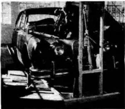
natural_image
Black-and-white photo of a vintage car on a construction platform, no visible text or symbols5.61c. Lifting engine · stage 3

natural_image
Black-and-white photo of a vintage sedan parked under a metal frame, no visible text or symbols5.62. Lifting engine - stage 4

natural_image
Black-and-white photo of a vintage car parked in a garage with visible engine and wheelbars (no text or symbols)5.63. Lifting engine - stage 5 sump clear
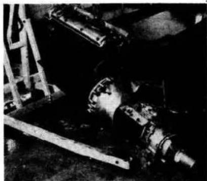
natural_image
Industrial machinery setup with metal components and ladder (no visible text or symbols)5.64. Lower engine to floor

natural_image
Technical line drawing of a mechanical clamp or bracket with four bolts and a ring (no text or symbols)Fig.1.3. The engine lifting plate

natural_image
Technical line drawing of an engine cylinder assembly (no text or labels)Fig.1.4. The engine lifting plate in use
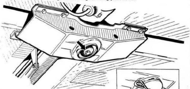
natural_image
Technical line drawing of a mechanical component with no visible text or symbolsFig.1.5. The rear engine mounting - fitting of washer and 1/8" diameter rod
6 Engine removal less gearbox
The engine may be removed less the gearbox if desired but it is felt that as there is so little work involved in disconnecting the gearbox from the car and as space for forward movement of the engine is so limited, it is preferable to remove the gearbox and engine as an assembly.
7 Engine removal with gearbox (from underside)
1 Follow the instructions given in Section 5, paragraph 1-53 (inclusive).
2 Move the car over a pit if not already so positioned.
3 Refer to Chapter 11 and remove the front suspension.
4 Sling the engine to take the weight off the mountings (see Section 5 paragraph 54). Remove the bolt securing the engine to each front mounting.
5 As a safety measure and to hold the engine steady, support the gearbox on a jack.
6 Place a large washer over the spigot protruding from the centre of the rear mounting and insert a 1/8" diameter rod through the hole in the spigot. This will hold the mounting spring compressed when the mounting is removed from the body.
7 Remove the bolts and packing washers fitted between the bracket and body floor taking note of the number and positions of the washers.
8 Slowly lower the jack from under the gearbox but have an assistant watching the engine in the bay because as the jack is lowered so will the engine take up an attitude with gearbox downwards.
9 Lower the engine slowly and inch it to the rear to clear the front mounting brackets. Remove the brackets if the attitude of the engine is such that they cannot be cleared.
10 Carry on lowering the engine; place some wooden battens on the floor on which the engine can be rested. Make sure that these are so positioned that the weight of the engine is evenly distributed.
11 To complete the job clear any loose nuts, bolts and tools
from the engine compartment and the floor and place them where they will not be lost.
8 Separating the engine from the gearbox (manual)
1 Remove the two bolts securing the starter to the clutch housing and remove the starter.
2 Tilt the engine to give access to the flywheel dust cover. Undo the four nuts and bolts securing the cover and remove it.
3 Remove the nuts and bolts securing the clutch housing to the engine, starting at the bottom and working towards the top. The box must be supported during this operation to avoid straining the clutch driven plate and the constant pinion shaft.
4 Carefully draw the gearbox rearwards clear of the engine.
9 Separating the engine from the transmission unit (automatic)
1 Drain the fluid from the transmission unit oil pan by removing the Allen screw using a 14 " AF key.
2 Remove the dipstick, detach the dipstick tube top securing clip and unscrew the tube from the oil pan. A special tool, Churchill Tool No.508, is available for this purpose but it will probably be found that sufficient purchase can be obtained using a strap wrench.
3 Remove the transmission unit retaining bolts commencing with the two bottom ones. Support the unit during this operation and place a container beneath the unit to catch the fluid from the converter when the transmission unit is withdrawn. DO NOT place supports immediately below the sump tray.
10 Removal and replacement of gearbox and clutch assembly - with engine installed
It was thought that it would be possible to remove and replace the gearbox and clutch assembly with the engine installed. It is not possible to do so without cutting away part of the bulkhead. The gearbox has to be pulled too far to the rear to clear the primary shaft of the flywheel and clutch.
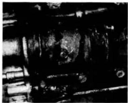
natural_image
Close-up of mechanical components with no visible text or symbols8.1a. Remove starter securing bolts
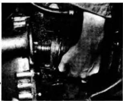
natural_image
Close-up of hands operating a mechanical component (no visible text or symbols)8.1b. Remove starter

natural_image
Black-and-white photo of a person interacting with a large object, possibly a device or tool, against a dark background (no visible text or symbols)8.2. Remove flywheel dust cover
8.3. Remove clutch housing securing bolts

natural_image
Close-up of a mechanical component with visible teeth and base, no text or symbols present11 Dismantling the engine - general
1 It is best to mount the engine on a dismantling stand, but if one is not available, stand the engine on a strong bench at a comfortable working height. It can be dismantled on the floor but this makes for very awkward and uncomfortable working.
2 During the dismantling process the greatest care should be taken to keep the exposed parts free from dirt. To that end, thoroughly clean down the outside of the engine, removing all traces of oil and congealed dirt. Use paraffin or a propriety solvent. The latter will make the job much easier for, after the solvent has been applied and allowed to stand for a time, a vigorous jet of water will wash off the solvent with all the dirt. If the dirt is thickly and deeply embedded, work in the solvent with a wire brush.
3 Finally wipe down the exterior of the engine with rag and only then when the engine is quite clean, should the dismantling process begin. As the engine is stripped, clean each part in a bath of paraffin or solvent.
4 Never immerse parts with oilways (for example the crankshaft) in the cleaning bath. To clean such items, carefully wipe down with a clean paraffin rag and wipe dry. Oilways can be cleaned out with nylon pipe cleaners or blown through with air blast.
5 Re-use of old engine gaskets, copper washers etc is false economy and will, in all probability, lead to oil or water leaks. Always use new items throughout.
6 Retain the old gaskets until the job is finished for it sometimes happens that an immediate replacement is not available and in such case the old item comes in very useful as a template. 7 When stripping the engine it is best to work from the top down but the underside of the crankcase, when supported on wood blocks, makes a firm base from which to work. It may be preferred, therefore, to remove the sump early on.
8 Whenever possible, replace nuts, bolts and washers finger tight from wherever they are removed. This helps to avoid loss and muddle later; if they cannot be replaced lay them out in such a fashion that it is clear from whence they came.
12 Removing the ancillary engine components
Before basic dismantling begins it is necessary to strip it of ancillary components as follows:-
Clutch - Fuel pipes under inlet manifold
Flywheel - Oil filter
Distributor — Thermostat
Oil supply pipes to camshaft - Water pump, crankshaft damper and pulley
1 Remove the clutch by slackening the mounting screws a turn at a time by diagonal selection until the thrust spring pressure is released. Remove the set screws and withdraw the clutch assembly from the flywheel. Note that the clutch and flywheel are balanced as an assembly and correct location should be marked by balance marks "B" on the clutch and flywheel. If the marks are not present, mark the clutch and flywheel assembly location yourself. Store the driven plate assembly so that the faces will not be contaminated by oil or dirt.
2 Knock back the tabs to the locking plate of the ten flywheel bolts. Undo the bolts and remove the locking plate. Remove the flywheel from the crankshaft by tapping with a hide faced hammer.
3 Slacken the distributor clamp plate bolt and remove the distributor. Remove the set screw and remove the clamp plate. Turn the engine to bring No.6 piston on TDC on the compression stroke and note the position of the offset driving slot.
4 Remove the oil supply pipes to the camshaft at the rear of the engine; note the fibre washers.
5 Unscrew the six connecting nuts and remove the fuel pipes from the underside of the inlet manifold.
6 Drain the upward pointing type of oil filter by removing the drain plug in the head of the assembly. Remove the two bolts holding the filter to the crankcase and remove the filter (both types). The upward pointing type is shown in the photograph adjacent but the method of attachment to the engine is the same for both types.
7 Slacken the clip securing the rubber hose from the water pump to the elbow on the top water rail and remove the hose from the elbow.
8 Unscrew the two nuts securing the elbow and remove it.
9 Remove the thermostat which is uncovered when the elbow union is removed. (see Chapter 2).
10 Slacken the clip securing the rubber hose to the water pump union and remove the hose.
11 Remove the bolts securing the water pump to the front cover and remove the pump.
12 Remove the bolts securing the centre bolt locking plate of the crankshaft damper.
13 Remove the damper securing bolt.
14 Prise the damper and pulley away from the engine off the split cone.
15 Remove the split cone and the distance piece and oil thrower behind it. Note the woodruff keys locating these items on the crankshaft; remove and store in a safe place. The engine is now stripped of all ancillary items and is ready for major dismantling to begin.
Fig.1.6. Balance marks on clutch and flywheel
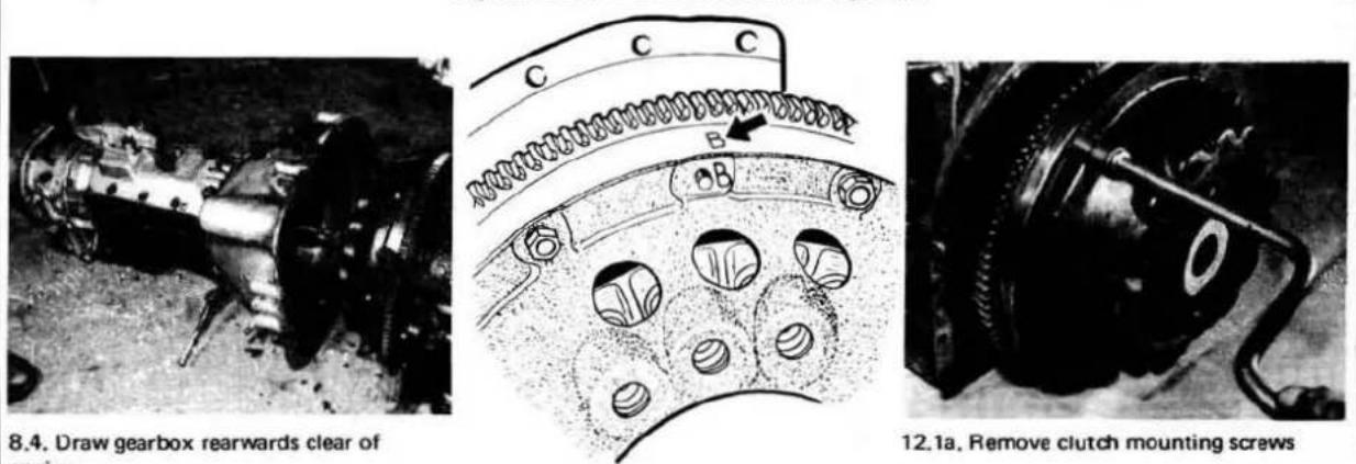
8.4. Draw gearbox rearwards clear of engine

natural_image
Close-up of a mechanical component with dark surfaces and visible wear (no text or symbols)12.1b. Lift off clutch assembly

natural_image
Close-up of a mechanical assembly with a circular component and a brake caliper (no visible text or symbols)12.2a. Undo flywheel bolts

natural_image
Close-up of hands adjusting a mechanical component with a circular housing (no visible text or symbols)12.2b. Remove flywheel
natural_image
Black and white abstract image with indistinct shapes and textures, no visible text or symbols12.3a. Remove distributor

natural_image
Close-up of a mechanical component with a circular hole and flanged base (no visible text or symbols)12.3b. Note position of offset slot

natural_image
Black-and-white photo of a mechanical device with two circular components and a rod inserted (no visible text or symbols)12.4. Remove camshaft oil supply pipes

natural_image
Close-up of a mechanical component with wires and a hand, no visible text or symbols12.5. Remove fuel pipes from inlet manifold

natural_image
Black-and-white photo of a person standing on a wooden board near a textured surface (no visible text or symbols)12.6a. Drain upward pointing type oil filter

natural_image
Black-and-white photo of a textured surface with indistinct shapes and no visible text or symbols12.6b. Remove oil filter

natural_image
Close-up of a mechanical component with no visible text or symbols12.10. Remove hose from water pump union

natural_image
Close-up of mechanical components with no visible text or symbols12.11a. Removing water pump bolts

natural_image
Close-up of mechanical components and tools, no visible text or symbols12.11b. Remove water pump

natural_image
Close-up of a mechanical component with concentric rings and a central hole (no visible text or symbols)12.12. Remove crankshaft damper locking plate

natural_image
Close-up of mechanical components with no visible text or symbols12.13. Removing crankshaft damper securing bolt
natural_image
Close-up of a dark, textured surface with no visible text or symbols12.14. Removing crankshaft damper and pulley
13 Cylinder head removal - engine on bench
1 Remove the eleven dome nuts securing each camshaft cover and remove the covers.
2 Remove the four nuts securing the engine breather at the front of the cylinder head. Remove the breather, the two gaskets and gauze filter (early cars will have a plate with two holes in lieu of the gauze filter).
3 In the space covered by the engine breather will be seen a serrated plate secured by a bolt. Knock up the tab washer to the bolt and slacken it. Depress the spring loaded plunger and rotate the plate in a clockwise direction (a pair of round nosed pliers entered in the holes in the plate is a handy tool for this) and this will relieve some of the tension in the top timing chain. Conversely, rotating the serrated plate anti-clockwise will tension the chain.
4 Break the locking wire to the two bolts securing the top sprocket to the camshaft.
5 It is a good tip at this stage to fit a thin nut (7/16" A/F) to the threaded end of the sprocket shaft outside of the support slide. A nut cut in half will suffice. The object of this is to retain
the sprocket and chain when disconnected from the camshaft and prevent them falling into the sump.
6 Remove the sprocket securing bolts.
7 Tighten down on the nut you have fitted to the sprocket shaft, this will pull the sprocket away from the camshaft.
8 Push the sprocket up the support slide to slacken the chain as much as possible and lock in this position with the nut holding the sprocket shaft on the spanner flats behind the support slide.
9 Repeat the above for the other sprocket.
10 Refer to Fig 1.8 and slacken the cylinder head nuts a part turn at a time in the order shown, (nuts 15-20 are below the head and above the front timing cover).
11 With the help of an assistant, lift off the cylinder head. If the gasket is partly stuck to the head, clean it off because, as it will catch on the cylinder head studs, it will prevent the head being lifted. Similarly watch the nut you have fitted to secure the sprocket as this may foul the front of the head if too thick or if the sprocket shaft is protruding too far.
12 Place the cylinder head on wooden blocks on the bench to avoid damage to the valves which will be protruding proud of the head at this stage.
natural_image
Close-up of a metallic mechanical component with textured surface (no visible text or symbols)12.15. Removing split cone

natural_image
Black-and-white photo of a person standing at a desk with equipment (no visible text or symbols)13.1. Remove camshaft covers
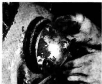
natural_image
Close-up of a mechanical component with a circular base and textured surface (no visible text or symbols)13.2. Removing engine breather

natural_image
Close-up of mechanical components with wires and connectors (no visible text or symbols)13.3. Rotate serrated plate clockwise

natural_image
Close-up of industrial machinery components with no visible text or symbols13.4. Break locking wire
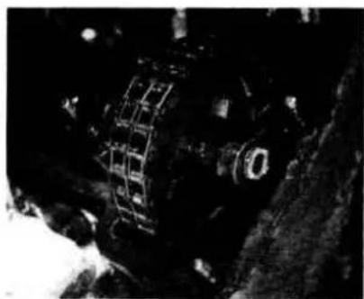
natural_image
Close-up of a mechanical component with textured surface and circular opening (no visible text or symbols)13.5. Fit thin nut to sprocket shaft

natural_image
Close-up of a mechanical component with a curved rod and textured surface (no visible text or symbols)13.6. Remove sprocket securing bolts

natural_image
Close-up of mechanical components with a wrench tool, no visible text or symbols13.7. Tighten nut on sprocket shaft
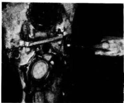
natural_image
Medical imaging scan showing internal anatomical structures (no visible text or labels)13.10. The nuts below the cylinder head
14 Cylinder head removal - engine in car
Read in conjunction with the instructions given in Section 5.
1 Disconnect the battery.
2 Drain coolant from the system in the manner described in Chapter 2.
3 Mark the position of the hinge brackets of the bonnet to facilitate refitting.
4 With the help of an assistant, take the weight of the bonnet and remove the two bolts securing it to each hinge. Lift the bonnet towards the front of the car and store in a safe place where it will not be damaged.
5 Remove the air cleaner and the air intake pipe at the carburettors.
6 Disconnect the flexible pipe to the engine breather at the front of the cylinder head.
7 Disconnect the top water hose to the radiator and the hose from the water pump at the elbow union at the top right hand side of the cylinder head.
8 Remove the radiator cowl (if fitted) and the radiator in the manner described in Chapter 2.
9 Slacken the dynamo mounting bolts and remove the fan belt. 10 Remove the fan.
11 Remove the nuts securing the exhaust manifolds to the cylinder head. Pull the manifolds away from the engine and secure them to take their weight and to keep them out of the way.
12 Disconnect the two clips securing the heater pipes at the rear of the engine and remove the two pipes.
13 Unscrew the nuts securing the heater assembly to the bulk-head so that the assembly can be pushed to one side slightly when lifting the cylinder head.
14 Detach the leads from the tags on the revolution counter AC generator at the rear of the right hand camshaft cover.
15 Disconnect the clutch fluid pipe at the bracket at the rear of the cylinder head.
16 Disconnect the leads to the automatic choke.
17 Disconnect the automatic choke to inlet manifold.
18 Disconnect the fuel feed between the carburettors and the fuel feed to the fuel filter.
19 Remove the split pin, plain and spring washers from the connecting link pivot pin located on the manifold between the carburettors and disconnect the throttle link rod joint from the ball pin on the bell crank lever.
20 Remove the clip attaching the overflow pipes from the float chambers to the oil filter mounting screw and disconnect the union connecting the starter pipe to the auxiliary starting carburettor.
21 Remove the carburettors.
22 Remove the throttle support linkage.
23 Detach the flexible rubber hose (brake servo) from the rigid pipe below the inlet manifold adjacent to the ignition distributor vacuum unit.
24 Detach the HT lead to the coil. Remove the clip securing the plug lead harness. Detach the plug leads at the plugs, remove the distributor head and remove the plug lead harness.
25 Detach the leads to the coil and remove the coil.
26 Detach the lead from the head of the temperature gauge indicator unit.
27 Refer to Section 12 and follow the instructions for the removal of the cylinder head.
15 Camshaft removal
1 Remove the bolts securing the plate holding the revolution counter generator to the cylinder head at the rear of the inlet camshaft. Note the inlet camshaft differs from the exhaust in that it has the generator drive in the rear end whereas the exhaust camshaft is plugged at this point.
2 Release the eight nuts securing the bearing caps a part turn at a time. Remove the nuts, spring washers and "D" washers from the bearing stud.
3 Remove the bearing caps, noting that the caps and the cylinder head are marked with corresponding numbers as illustrated in Fig 1.9. Also note that the bearing caps are located to the lower bearing housings with hollow dowels.
4 Lift out the camshaft.
5 Remove the camshaft bearing shells from the cylinder head and keep them with their counterparts for correct reassembly in their original positions (if new items are not fitted). Important do not rotate a camshaft when the other shaft is fitted as the valves will foul each other.
6 Repeat the above (except for revolution counter generator) for the exhaust camshaft.
16 Valve removal
1 Make some arrangement to keep the valves, springs, tappets and adjusting pads related to each other and to their position in the cylinder head. A board as illustrated in photograph 16.1 is ideal for this purpose.
2 Make up a wooden block as illustrated in Fig 1.10 to support the valves when compressing the springs.
3 Remove the tappets. A valve grinding suction tool applied to the head of the tappet makes this an easy task.
4 Remove the valve adjusting pad if it has not adhered to the tappet. Keep it and the tappet together.
5 Place the wooden valve support block beneath the cylinder head to support the valves.
6 Compress the valve spring and have an assistant remove the cotters as they are released. We found that an easy way to remove the cotters is to place a piece of steel tubing, approximately 34 " internal diameter and 9" in length, over the end of the spring, strike the tube a sharp blow with a hammer and the cotters will fall out on their own accord.
7 Remove the valve collar, the springs, the valve and the valve spring seat and keep them as a set for the position from which they were removed.
8 Repeat the above for the removal of all the valves.

natural_image
Black-and-white photo of a vintage mechanical device with visible components and no readable text or symbols13.11. Lift off cylinder head

natural_image
Close-up of a hand operating a mechanical component with no visible text or symbols15.1a. Removing the revolution counter generator

natural_image
Close-up of a hand holding a mechanical component, possibly a valve or clamp, with no visible text or symbols.15.1b. The revolution counter drive

natural_image
Close-up of two bolts with visible nuts, resting on a textured surface (no text or symbols)15.1c. Inlet camshaft left. Exhaust camshaft right

natural_image
Close-up of a hand operating a mechanical component with no visible text or symbols15.2. Camshaft bearing cap 'D' washer
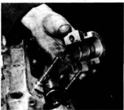
natural_image
Close-up of mechanical components with no visible text or symbols15.3. Note hollow dowels locating bearing cap
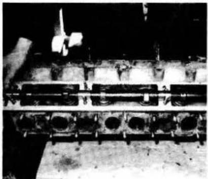
natural_image
Close-up of a mechanical engine component with multiple cylindrical cavities and a hand adjusting the shaft (no visible text or symbols)15.4. Lift out camshaft

natural_image
Close-up of a hand using a tool to adjust or install a mechanical component (no visible text or symbols)15.5. Remove camshaft bearing shells

natural_image
Close-up of hands operating a mechanical device with no visible text or symbols15.6a. Remove plate at rear of exhaust camshaft
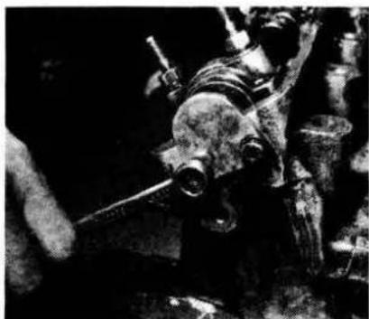
natural_image
Black-and-white photo of a mechanical device with visible gears and components (no text or symbols)15.6b. Securing plate and sealing plug at rear of exhaust camshaft

FIG.1.7. EXPLODED VIEW OF THE CYLINDER HEAD
1 Cylinder head
2 Camshaft bearing cap and cover stud
3 Ring dowel
4 'D' washers
5 Core plug
6 Copper washer
7 Inlet valve guide
8 Insert for inlet valve
9 Guide for tappet
10 Cylinder head gasket
11 Cylinder head stud
12 Exhaust manifold stud
13 Inlet manifold stud
14 Camshaft cover stud
15 Breather housing stud
16 Inlet valve
17 Exhaust valve
18 Inner valve spring
19 Outer valve spring
20 Valve spring seat
21 Valve stem collar
22 Valve stem cotters
23 Valve tappet
24 Valve clearance adjusting pad
25 Inlet camshaft
26 Exhaust camshaft
27 Camshaft bearing shell
28 Exhaust camshaft oil
29 Setscrew
30 Copper washer
31 Sealing ring
32 Flanged sealing plug
33 Rear camshaft bearing seal
34 Driving dog adaptor
35 Driving dog
36 Circlip
37 Rev. counter generator
38 'O' ring
39 Screw
40 Plate washer
41 Lock washer
42 Inlet camshaft cover
43 Gasket
44 Exhaust camshaft cover
45 Gasket
46 Dome nut
47 Copper washer
48 Oil filler cap
49 Fibre washer
thrower
50 Oil pipe
51 Banjo bolt
52 Copper washer
53 Front cover and breather
54 Gauze filter
55 Gasket
56 Dome nut
57 Elbow hose
58 Clip
59 Breather pipe
60 Hose
61 Clip
62 Elbow
63 Gasket
64 Exhaust manifold (front)
65 Exhaust manifold (rear)
66 Exhaustmanifold (front)
67 Exhaustmanifold (rear)
68 Gasket
69 Stud
70 Sealing ring
71 Inlet manifold
72 Gasket
73 Adaptor
74 Copper washer
housing
75 Pivot pin
76 Spring washer
77 Adaptor
78 Brake vacuum servo pipe
79 Rubber sleeve
80 Hanger bracket
81 Clamp
82 Bracket
83 Stud
84 Starting pipe (L.H.)
85 Starting pipe (R.H.)
86 Starting pipe
87 Neoprene tube
88 Clip
89 Water outlet pipe
90 Gasket
91 Stud
92 Stud
93 Thermostat
94 Thermostat, automatic
95 Gasket
96 Water outlet elbow
97 Gasket
choke
17 Valve and tappet guide - removal
The valve and tappet guides are shrunk into the cylinder head and although their removal is a fairly simple task it is not recommended that you do this because their replacement is too difficult to do accurately. It is far better to leave this task to a Jaguar garage.
18 Sump, piston, connecting rod and big end bearing - removal
The sump, pistons and connecting rods can be removed with the engine still in the car or with the engine on the bench. Proceed with the appropriate methods in either case for removing the cylinder head and for removing the front suspension. The pistons and connecting rods are drawn up out of the top of the cylinder bores.


natural_image
Technical line drawing of a mechanical joint or connector with no visible text or symbolsFig.1.9. Corresponding numbers on cylinder head and camshaft bearing cap
Fig.1.8. Tightening sequence of cylinder head studs
![WOOD BLOCKS 1½[33mm] 1½[42·8 mm] Radius BASE 3²³/₅₂ [96 mm] 3²³/₅₂ 4 ¾/₈ [111 mm] 3²³/₅₂ 3²³/₅₂ 6" [152 mm]](/content/2026/05/1021110/images/9326bd0ef0a52230bde97527e3c93562a64a0eea5fd126c66133ccba6753e218.jpg)
Fig.1.10. Wooden block to support valves

natural_image
Technical line drawing of mechanical components including bolts, nuts, and a bearing (no text or symbols)Fig.1.11. Valve tappet and adjusting pad

natural_image
Close-up of a metallic electronic component with multiple circular holes and a labeled pin (no readable text or symbols)16.1. Board to hold valves

natural_image
Close-up of a hand operating a mechanical component (no visible text or symbols)16.3. Remove tappets

natural_image
Close-up of a hand operating a mechanical tool on a workbench (no visible text or symbols)16.4. Remove valve adjusting pad

natural_image
Close-up of a wooden beam with rectangular cutouts and bolt holes (no text or symbols visible)16.5. Place wooden support block beneath cylinder head

natural_image
Close-up of hands operating a mechanical tool or tool (no visible text or symbols)16.6. Removing valve springs

natural_image
Close-up of a hand using a tool to adjust or install a mechanical component (no visible text or symbols)16.7a. Remove valve collar

natural_image
Close-up of a hand operating a mechanical component with a metallic shaft (no visible text or symbols)16.7b. Remove valve springs

natural_image
Close-up of a damaged mechanical component with visible wear and bolt holes (no text or symbols)18.2a. Removing filter assembly
natural_image
Black-and-white abstract image with a dark, irregular shape and faint smudges (no text or symbols)18.2b. The oil sump filter
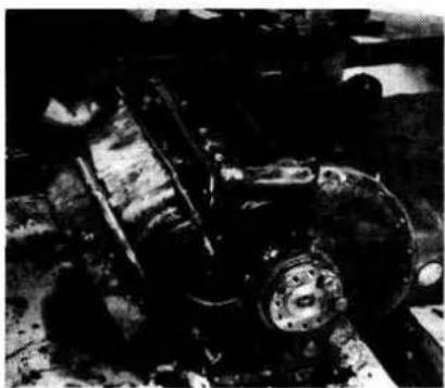
natural_image
Close-up of mechanical components with no visible text or symbols18.2c. Remove the sump

natural_image
Close-up of mechanical components with a metallic tool inserted, no visible text or symbols18.3. Remove big-end cap nuts

natural_image
Black-and-white photo of a mechanical component or tool, possibly a valve or pump, with no visible text or symbols.18.4a. Marking of connecting rod and bearing cap
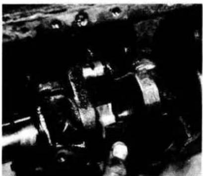
natural_image
Close-up of mechanical components or parts in a dark, textured surface (no visible text or symbols)18.4b. Remove big-end bearing cap

natural_image
Close-up of a mechanical component with cylindrical and flanged parts (no visible text or symbols)18.6. Withdraw piston and connecting rod
1 Turn the engine on its side, if on the bench.
2 Remove the sump by unscrewing the twenty six set screws securing the sump to the crankcase and, if the engine is installed in the car, the four nuts securing it to the timing cover. Note that a short set screw is fitted at the right hand front corner of the sump. It may be found that the oil suction pipe fouls the filter gauze in the sump and prevents removal of the sump. In that event the gauze assembly will have to be removed by removing the retaining bolts (your car may not be fitted with the type depicted).
3 Undo the split pins and remove the nuts to the big-end bearing caps, self locking nuts are used in later models.
4 Remove the big-end bearings caps and shell bearings. Note that the big-end bearing cap and the connecting rods are marked with the number of the cylinder to which they belong and that the numbers on the rod and cap are together. If they are not so marked, or if there is any doubt, stamp them or mark them in some way for correct reassembly.
5 If the bearings are not to be changed, keep them with their respective caps and connecting rods.
6 Withdraw the pistons and connecting rods upwards and lay them out in their correct order for replacement in the same bore. Refit the caps and bearings to the connecting rods and replace the nuts finger tight to keep them in position.
19 Timing gear - removal
1 Remove the front timing cover by undoing the set bolts. Note that the cover is located by two dowels, ensure that these are a tight fit in the cylinder block. Remove them if they are loose, to prevent loss.
2 Remove the bottom timing chain tensioner by knocking up the tab washer and undoing the hexagon plug from the end of the body. Next insert an Allen key (0.125 A/F) into the hole until it registers in the end of the restraint cylinder, turn the key clockwise until the restraint cylinder can be felt to be fully retracted within the body. The adjuster head will now be free of the chain.
3 Open the tab washers to the two bolts securing the chain tensioner to the cylinder block, withdraw the bolts and remove the tensioner together with the backing plate and shim. Note the conical gauze filter fitted in the tensioner oil feed hole in the cylinder block, this should be removed for subsequent cleaning.
4 Remove the bolt holding the serrated adjuster plate. Remove the plate and the spring loaded plunger.
5 Unscrew the four set bolts securing the front mounting bracket of the timing gear to the cylinder block. Release the tabs of the tab washers and remove the two screwdriver slotted set screws from the rear mounting bracket; on the 3.4,3.8 litre and 340 models these screws also secure the intermediate timing chain damper bracket.
6 Lift out the left and right hand upper chain damper assembly and distance pieces and the vibration damper for the lower chain which have now been released by removal of the mounting bolts.
7 Disconnect the bottom chain and lift the timing gear assembly away from the cylinder block.
8 Remove crankshaft timing gear sprocket. Note the Woodruff key.

natural_image
Black-and-white photo of a mechanical device with no visible text or symbols19.1. Remove front timing cover

natural_image
Close-up of hands operating a mechanical chain drive (no visible text or symbols)19.2. The bottom timing chain tensioner

natural_image
Close-up of mechanical components with no visible text or symbols19.4a. Bolt holding serrated adjuster plate
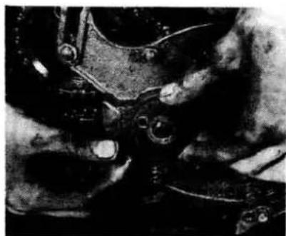
natural_image
Close-up of mechanical components with no visible text or symbols19.4b. Removing serrated plate and spring loaded plunger

natural_image
Close-up of an engine cylinder head with visible internal components and a tool inserted (no text or symbols)19.5a. Removing front mounting bolts

natural_image
Close-up of an engine cylinder head with visible internal components and mounting holes (no text or symbols)19.5b. Removing screwdriver slotted setscrews

FIG.1.12. EXPLODED VIEW OF THE CYLINDER BLOCK
1 Cylinder block
2 Core plug
3 Plug
4 Plug
5 Copper washer
6 Front timing cover
7 Plug
8 Plug
9 Copper washer
10 Dowel
11 Stud
12 Dowel stud
13 Cover
14 Ring dowel
15 Bolt
16 Bolt
17 Spring washer
18 Sealing ring
19 Ring dowel
20 Cap screw
21 Water drain tap
22 Copper washer
23 Fibre washer
24 Dynamo mounting bracket
25 Crankshaft
26 Screwed plug
27 Bush
28 Thrust washer
29 Main bearing (front,
centre and rear)
30 Main bearing (intermediate)
31 Crankshaft damper
32 Cone
33 Distance piece
34 Oil thrower
35 Timing chain gear
36 Oil pump drive gear
37 Key
38 Pulley
39 Bolt
40 Shakeproof washer
41 Bolt
42 Washer
43 Tab washer
44 Connecting rod
45 Big end bearing
46 Flywheel
47 Dowel
48 Dowel
49 Setscrew
50 Locking plate
51 Piston
52 Pressure ring (upper)
53 Pressure ring (lower)
54 Scraper ring
55 Gudgeon pin
56 Circlip
57 Oil sump
58 Gasket
59 Seal
60 Cork rubber seal
61 Drain plug
62 Copper washer
63 Oil sump filter basket
64 Cover
65 Gasket
66 Hose
67 Clip
60 Dipstick
69 Flexible oil pipe from
oil filter
70 Copper oil pipe to
pressure gauge
71 Flexible oil pipe from copper
oil pipe to pressure gauge
72 Front engine mounting
bracket (left hand)
73 Front engine mounting
bracket (right hand)
74 Front engine mounting
75 Flange support bracket
(left hand)
76 Flange support bracket
(right hand)
77 Stabilizing link
78 Bush
79 Stepped washer
80 Stepped bush
81 Stabilizer rubber mounting
82 Stabilizer mounting bracket
on clutch housing
83 Channel support
84 Rubber spring seat
85 Rubber centre bush
86 Spring retainer
87 Coil spring
88 Packing block
89 Stiffening plate
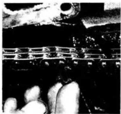
natural_image
Close-up of a mechanical component with textured surfaces and a cylindrical part (no visible text or symbols)19.7a. Disconnect bottom chain

natural_image
Interior view of an engine bay with visible mechanical components and structural elements (no text or symbols)19.7b. Lift away timing gear

natural_image
Close-up of hands holding a mechanical component (no visible text or symbols)19.8. Crankshaft timing gear sprocket
20 Gudgeon pin - removal
bath of hot oil. After a few minutes it will be found that the pin will move quite easily.
5 Push out the pin far enough to clear the small end of the connecting rod. Separate the piston and connecting rod. Do not push the gudgeon pin right out of the piston unless absolutely necessary, if it does come clear of the piston make sure that it is replaced in its original position.
6 The piston should be marked with the number of the cylinder to which they belong. If they are not marked ensure that they are correctly identified because it is important that they are reassembled to the bore from which they were removed.
21 Piston ring - removal
1 To remove the piston rings, slide them over the top of the piston taking care not to scratch the surface of the piston and not to distort the rings. Never slide them off the bottom of the piston skirt. Piston rings are very brittle and are easily broken if they are pulled off roughly. It is helpful to use an old feeler gauge blade to facilitate their removal.
2 Lift one end of the piston ring to be removed out of its groove and insert the end of the feeler gauge under it.
3 Turn the feeler gauge slowly round the piston and as the ring comes out of its groove it rests on the land above. It can then be eased off the piston with the feeler gauge stopping it from entering an empty groove if it is any but the top ring that is being removed.
22 Oil pump assembly - removal
1 Remove the nut and bolt securing the oil pump inlet pipe clip to the bracket on the main bearing cap.
2 Tap back the tab washers and unscrew the two set bolts securing the oil feed pipe flange to the bottom of the crankcase.
3 Open the tab washers from the three bolt heads securing the oil pump to the front main bearing cap, remove the bolts.
4 The oil pump can now be withdrawn.
23 Distributor drive - removal
1 Tap back the tab washer securing the distributor drive gear nut and remove the nut and washer.
2 Tap the squared end of the distributor drive shaft through the gear; note that the gear is keyed to the shaft.
3 Remove the gear and thrust washer and withdraw the shaft.
4 Remove the distributor/oil pump helical drive gear. Remove the key locking it to the shaft.
24 Crankshaft - removal
1 Knock back the tab washers securing the fourteen main bearing cap bolts.
2 Note the corresponding numbers stamped on the caps and the bottom face of the crankcase. The caps must be correctly identified if they are not marked.
3 Undo the bolts and remove the main bearing caps. If the main bearing shell does not come away with the cap, remove it from the crankshaft and keep it with its cap.
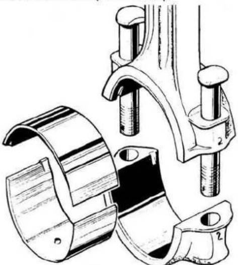
natural_image
Technical illustration of mechanical components with no visible text or symbolsFig.1.13. Connecting rod and cap stamped with cylinder number

natural_image
Line drawing of a mechanical component with curved blades and central hub (no text or symbols)Fig.1.14. The crankshaft thrust washers
4 Note the thrust washers fitted in the recesses in the centre main bearing cap.
5 Detach the bottom of the oil return thread cover from the top half by removing the two Allen securing screws. Note that the two halves are located by hollow dowels.
6 The crankshaft can now be lifted away from the crankcase.
7 Collect the remaining halves of the main bearing shells and, if they are to be refitted, identify them with the position from which they were removed.
25 Lubrication system · description
A force feed system of lubrication is employed with oil being circulated round the engine from the sump below the cylinder block. The level of the oil in the sump is indicated by the dipstick which is fitted on the left hand side of the engine. High and low level of oil is indicated by marks on the dipstick; ideally the level of oil should not be above the high mark and should never be allowed to fall below the low mark. Oil is replenished via the filler cap in the left hand camshaft cover. The oil is circulated round the engine by an eccentric rotor type oil pump which consists of five main parts: the body, the driving spindle with the inner rotor pinned to it, the outer rotor and the cover which is secured to the main body by four bolts. The pump is illustrated in Fig 1.28. Oil is drawn from the sump and is then passed under pressure by the pump to the filter on the right hand exterior of the crankcase and thence through drillings to the big end, main and camshaft bearings. A longitudinal drilling through the connecting rod feeds the small end and gudgeon pin with oil and

natural_image
Black-and-white photo of a person standing in front of a large industrial machine with visible components and wiring (no text or symbols)22.1. Remove oil pipe clip

natural_image
Close-up of a mechanical component with a central shaft and flange (no visible text or symbols)22.2. Undo oil feed pipe flange
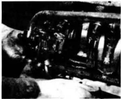
natural_image
Close-up of a mechanical component with visible internal structure and textured surface (no text or symbols)22.4. Withdraw oil pump

natural_image
Black-and-white photo of a mechanical tool with a cylindrical component and two metal rods, resting on a textured surface (no visible text or symbols)23.1. Remove distributor drive gear nut

natural_image
Close-up of a mechanical device with gears and a hand resting on it (no visible text or symbols)23.3. Remove distributor drive gear and thrust washer

natural_image
Close-up of a mechanical component with no visible text or symbols23.4a. The helical gear, oil pump drive

natural_image
Close-up of a metallic cylindrical object with textured surface and dark markings (no visible text or symbols)23.4b. Woodruff key on crankshaft (typical)
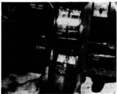
natural_image
Black-and-white photo of a building interior with visible structural elements and no readable text or symbols24.3. Remove main bearing caps

natural_image
Close-up of a hand using a tool to adjust or install a mechanical component (no visible text or symbols)24.5a. Undo oil thread cover Allen screws

natural_image
Close-up of mechanical components with no visible text or symbols24.5b. Detach bottom half of oil thread cover
a small hold in each connecting rod throws a small jet of oil to the cylinder wall with each revolution. The camshafts are fed through an exterior pipe at the rear of the engine, the oil then passes along a longitudinal drilling in each camshaft and is fed to the bearings through drillings in each cam.
The external oil filter is of the full flow type with a replaceable element. There are two patterns of filter, the first an upward pointing type which is fitted to early models and the second a downward pointing type fitted to later model cars, typical examples of each illustrated in Figs 1.50 and 1.16 respectively. The two types of filter assembly are not interchangeable and the filter elements differ, it is essential, therefore, to quote the engine number when ordering a new filter element. The head of the filter assembly incorporates a removable oil pressure relief valve and a balance valve which provides a safeguard against the possibility of the filter element becoming so choked as to prevent oil reaching the bearings.

natural_image
Close-up of a hand operating a mechanical component with visible bolts and surface paint (no text or symbols)24.6. Lift out crankshaft
26 Oil filter - removal and replacement
1 The external oil filter is of the disposable cartridge type and is located on the right hand side of the engine. It is most important to renew the filter element at the recommended periods (5000 mile servicing) as at this mileage it is becoming choked with impurities.
2 Place a tray on the floor beneath the oil filter.
3 Drain the upward pointing type by removing the drain plug from the bottom of the head. Replace the plug after draining.
4 Remove the central bolt securing the canister to the head and remove the canister complete with the filter element. The canister of the downward pointing type will be full of oil at this stage so it must be kept upright until placed to drain.
5 Remove the rubber sealing ring from the head of the oil

FIG.1.15. OIL FILTER – UPWARD POINTING TYPE
1 Oil filter assembly
2 Canister
3 Spring
4 Plain washer
5 Felt washer
6 Pressure plate
7 Bolt
8 Rubber washer
9 Spring clip
10 Element
11 Filter head
12 Oulet adaptor
13 Sealing washer
14 Clamping plate
15 Anchor insert
16 Sealing ring
17 Union screw
18 Copper washer
19 Relief valve
20 Spring
21 Dome nut
22 Stop pin
23 Washer
24 Drain plug
25 Sealing washer
26 Blanking plate
27 Gasket
28 Gasket
29 Hose
30 Clip
FIG.1.16. OIL FILTER - DOWNWARD POINTING TYPE
1 Oil cleaner
2 Canister
3 Spring
4 Plain washer
5 Felt washer
7 Bolt
8 Rubber washer
9 Spring clip
10 Element
11 Anchor insert
12 Clamping plate
13 Sealing ring
14 Filter head
15 Balance valve
16 Seal
17 Relief valve
18 Spring
19 Spider and pin
20 Adaptor
21 Seal
22 Gasket
23 Hose
24 Clip

filter.
6 Remove and discard the old element.
7 Withdraw the canister retaining bolt and note the order of assembly of the spring clip, the pressure plate (and which way up it faces), the felt washer, the plain washer and spring.
8 Thoroughly clean all parts, especially the interior of the canister where it will be found that sediment has collected in the base and this will probably have to be removed using paraffin and a brush.
9 Reassemble the filter in the reverse order to the above but fitting a new element, rubber sealing ring in the head and a new felt and rubber washer on the canister securing bolt.
27 Engine - examination and renovation - general
With the engine stripped and all parts thoroughly cleaned, every component should be examined for wear. The following items should be checked and, where necessary, renewed or renovated as described later.
28 Crankshaft - examination and renovation
1 Examine the crankpin and main journal surfaces for signs of scoring or scratches and, where bearings are thought to have failed, for white metal adhering to them. White metal contamination can be removed by very light rubbing with fine crocus paper. If the journals are scored the crankshaft should be re-ground or a factory reconditioned item fitted as can be obtained on an exchange basis provided the old shaft is fit for reconditioning.
2 Clean the journals and crankpins and measure the diameter at different positions with a micrometer. Regrinding is generally recommended when wear or ovality in excess of 0.003" (0.08mm) is found. Details of the basic diameter of the journals and crankpins will be found under the specification at the beginning of this Chapter.
3 Ensure that the oil passages are clear.
4 If the original crankshaft is to be refitted, remove the Allen headed plugs in the webs and thoroughly clean out any accumulated sludge using a high pressure jet followed by blowing out with compressed air.
5 Replace the plugs and secure in position by staking with a centre punch or a blunt chisel.
29 Crankshaft pulley and damper - examination and renovation
1 The rubber portion of the damper should be examined for deterioration. If the rubber appears to have perished it should be replaced.
2 The drive on the pulley should be taken on the "V". Check that the fan belt does not bottom. If it does, recheck with a new fan belt; if this does not bottom, renew the fan belt. If the new belt bottoms, renew the pulley.
3 Note that the damper and pulley are balanced as an assembly at production and if they are to be separated they should be marked for correct reassembly.
30 Big end and main bearings - examination and renovation
1 Big end bearing failure is usually accompanied by a noisy knocking from the crankcase and a drop in oil pressure. Main bearing failure give rise to vibration which can be quite severe as the engine speed increases and reduces, a drop in oil pressure will also be noticed. However, if engine vibration is experienced do not immediately jump to the conclusion that the main bearings have failed because there are a number of other factors which can cause this.
2 Inspect the big ends, main bearings and thrust washers for signs of general wear, scoring, pitting and scratches. The bearings should be a matt grey in colour. Should a trace of copper be noticed in lead indium bearings, the bearings are badly worn for the lead bearing has worn away to expose the indium underlay. Renew the bearings if they are in this condition or if there is any sign of pitting or scoring.

natural_image
Exploded view diagram of a mechanical assembly showing internal components like gears, shafts, and housing (no text or labels)Fig.1.17. Crankshaft damper and pulley assembly

natural_image
Close-up of a mechanical component with circular holes and a central shaft (no visible text or symbols)28.1. Scored crankpin journal

natural_image
Close-up of two metallic curved mechanical components on a dark surface (no text or symbols visible)30.2a. Unserviceable crankshaft thrust washers

natural_image
Close-up of two cylindrical mechanical components with a dark shaft and light reflections (no visible text or symbols)30.2b. Scored big-end bearing shells
3 The undersizes available are designed to correspond with regrind sizes in steps of -0.010". The bearings are in fact slightly larger than the stated undersize as running clearances have been allowed for during their manufacture.
4 Bearing shells must be changed in pairs. It is no use fitting a new half bearing to one that has been in use.
5 Very long engine life can sometimes be achieved by changing big-end bearings at 30,000 and main bearings at 50,000 miles respectively, irrespective of the visual condition of the bearings. Normally, crankshaft wear is infinitesimal and regular changes of bearings may ensure mileages of between 100,000 and 120,000 miles before regrinding becomes necessary. Crankshaft wear and scoring is usually the result of bearing failure.
6 Despite the foregoing, it is recommended that whenever the engine is dismantled new bearing throughout should be fitted on reassembly.
31 Flywheel - examination and renovation
1 Examine the starter teeth for wear or damage which, if found will necessitate replacement of the flywheel.
2 The new flywheel and clutch must be balanced as an assembly. (See Fig 1.6).
3 Mount the assembled flywheel and clutch on a mandrel and set up on parallel knife edges.
4 Find the balance point and mark the relative position of the clutch and the flywheel.
5 If necessary to obtain balance, remove the clutch and drill 0.375" (9.5 mm) holes not more than ½" (12.7 mm) deep at a distance of 0.375" (9.5 mm) from the edge of the flywheel.
6 However it will be appreciated that this is a task best left to a Jaguar garage having the necessary equipment and experience.
32 Cylinder block - examination and renovation
1 Thoroughly clean the top face of the cylinder block and check it for truth with a straight-edge.
2 Examine the top face of the block for damage. Pay particular attention to the condition of the face between the webs of the cylinder bores, look for burning or cracks.
3 Examine the cylinder bores for taper, ovality, scratches and scores. Start by carefully examining the top of the bores, if they are worn fractionally a very slight ridge will be felt on the thrust side. This marks the top of the piston travel. You will have a good indication of the condition of the bores before dismantling the engine, or removing the cylinder head as excessive oil consumption accompanied by blue smoke from the exhaust is a sure sign of excess wear.
4 Measure the diameter of the bore just under the ridge with an internal micrometer or vernier and compare it with the diameter at the bottom of the bore which is not subject to the same amount of wear. If the difference between the two measurements is greater than 0.006" (0.1524 mm) it will be necessary to fit a "ring set" or to rebore and fit oversize pistons and rings. If you do not have a micrometer, remove the rings from a piston and place it in each bore in turn about 14 " from the top of the bore. If a 0.010" (0.254 mm) feeler gauge can be entered between the piston and the cylinder wall on the thrust side of the bore then remedial action must be taken. Refer to the specifications at the beginning of this Chapter for rebore sizes. The present size of the bore (ie +0.10,+0.20 etc) should be found marked on the cylinder block face alongside each bore.
5 Oversize pistons are available in the following sizes:
+0.010 inch (0.254 mm) +0.030 inch (0.76 mm)
+0.020 inch (0.51 mm)
There are no selective grades in oversize pistons, (see Section 33).
6 The maximum limit for reboring +0.030" (0.762 mm). Liners and standard size pistons should be fitted when bores will not clean up at that limit.
7 If the bores are slightly worn but not so badly as to justify
reboring them, special oil control rings can be fitted to the existing pistons which will restore compression and stop the engine burning oil. Several different types are available and the manufacturer's instructions concerning their fitting must be followed closely. However, fitting special rings is a comparatively short term remedy; if the engine is out of the car and completely stripped it seems false economy not to return the engine to an "as new" condition by reboring.
8 Remove the six brass blanking plugs in the main oil gallery and thoroughly clean out the cylinder block oilways and the interior of the crankcase.
33 Pistons and piston rings - general
The pistons of the 2.4 and 3.4 Mk 1 models have two compression and one oil control ring, the top compression ring being hard chrome plated; tapered periphery compression rings are fitted on the 3.4 litre car.
The pistons of the 2.4 litre Mk.2 and the 240 model, have four rings each, three compression and one oil control. The top compression ring only is chromium plated and the other two have a tapered periphery.
In the case of the 3.4 Mk.2 and the 3.8 litre and the 340 engines, the pistons have three rings each, two compression and one oil control. The top compression ring is chromium plated and both the top and second compression rings have a tapered periphery. "Maxiflex" type oil control rings are fitted to later engines and if desired may be fitted to those engines which do not incorporate them. 2.4 litre pistons will require modification to accept these rings. The modification consists of drilling a 0.125" diameter hole in the centre of the oil control ring groove in line with the gudgeon pin bore, as shown in Fig 1.20, to accept the ends of the equaliser.
The pistons fitted to an engine should not vary in weight one with another by more than 3.5 grammes; replacements are, therefore, supplied in sets.

natural_image
Exploded view diagram of an internal combustion engine cylinder and piston assembly (no text or labels)Fig.1.18. Exploded view of the connecting rod and piston assembly
Five selective grades of piston are available in standard sizes only. If you have to order a set of standard pistons you will have to quote the identification letter of the selective grade either F, G, H, J or K. This identification letter is stamped on the crown of the piston and is stamped also on the top face of the cylinder block adjacent to the bores.
Oversize pistons are available in the following sizes:-
+ 0.010 inch (0.25 mm) 0.030 inch (0.76 mm)
+ 0.020 inch (0.51 mm)
There are no selective grades in oversize pistons.
The various types of piston for the various compression ratios are shown in Fig 1.21 from which it will be seen that although the 2.4 and the 3.4 litre engine pistons are of similar diameter, they are not interchangeable.
It must be noted that 240 engines are produced with an 8:1 compression ratio only and the 340 model is available with a compression ratio of 8:1 as standard and 9:1 as an optional.
34 Pistons, piston ring and gudgeon pin - examination and renovation
1 The method of removing the gudgeon pin and the piston rings has already been described in Section 19 and 20 respectively.
2 Remove the piston rings.
3 Clean carbon from the head of the piston using worn emery cloth and paraffin. Do not use a scraper or any tool that may score the head.
4 Do not use an abrasive to clean the outside of the piston, despite the discolouration that may be present; a wipe with a cloth and paraffin will suffice.
5 Examine the lands for burrs and these may prevent freedom of movement of the ring, rectify as necessary using fine emery cloth.
6 Clean all dirt out of the grooves especially in the corners. A broken piston ring is a handy tool for this job but be careful not to dig in or remove metal.
7 Examine the skirt for fractures at the extremity of the split.
8 When a new piston ring is brought into use its gap, when sprung out in the cylinder bore, must be measured. If the gap is too small seizure will result when the ring expands; if the gap is too great compression pressure will be lost.
9 Push the new ring down the bore as far as possible using a piston for this to ensure that the ring is square in the bore.
10 Refer to Fig 1.22 and measure the gap using a feeler gauge. The correct gaps are:-
Compression rings .....0.015 to 0.020" (0.38 to 0.51 mm)
Oil control rings 0.011 to 0.016" (0.28 to 0.41 mm)
Oil control rings Maxiflex 0.015 to 0.038" (0.38 to 0.83 mm)
Adjust with a fine file if the gap is too small.
11 Check the side clearance of the ring in its groove, this should be 0.001 to 0.003" (0.025 to 0.076 mm).
12 All engines are fitted with taper periphery rings in at least one position and it is essential that these are fitted the correct way up. The narrowest part of the ring must be fitted uppermost and this can be identified by the letter "T" or TOP stamped on the face (See Fig.1.23).
13 Apply pressure longitudinally to the gudgeon pin through the connecting rod. Watch for movement of the pin in the piston and if movement is noted the piston and pin must be replaced.
35 Connecting rods - examination and renovation
1 If the connecting rods have been in use for a very high mileage or if bearing failure has been experienced it is advisable to renew the affected rods owing to the possibility of fatigue failure.
2 The alignment should be checked and corrected as necessary on an approved connecting rod alignment jig. Arrangements should be made for this to be done at your local Jaguar garage.
3 Check that the big end caps have not been filed. If they have,

natural_image
Close-up of a textured, dark vertical surface with no visible text or symbols32.2. Cracked and burnt cylinder block

natural_image
Close-up of two metallic bolts mounted on a dark metal rod (no visible text or symbols)32.8. Two of the six brass plugs to the main oil gallery
there is no alternative but to replace the connecting rod complete.
4 Check "rock" of the connecting rods on the gudgeon pin. If movement is observed and it can be established that this is due to wear at the small end, a new small end bush must be fitted.
5 Remove the gudgeon pin in the manner described in Section 19, discard the circlips, new items must be fitted on reassembly.
6 The small end bush is a press fit in the connecting rod. Force it out using a vice or press and fit a new item. Ream the new bush after fitting to a diameter of 0.875" to 0.8752" (22.225 to 22.223 mm)
36 Camshaft and camshaft bearings - examination and renovation
The camshaft and bearings normally give a very long life but there are always exceptions to the rule. The photograph adjacent shows a camshaft which has failed due to a breakdown in the
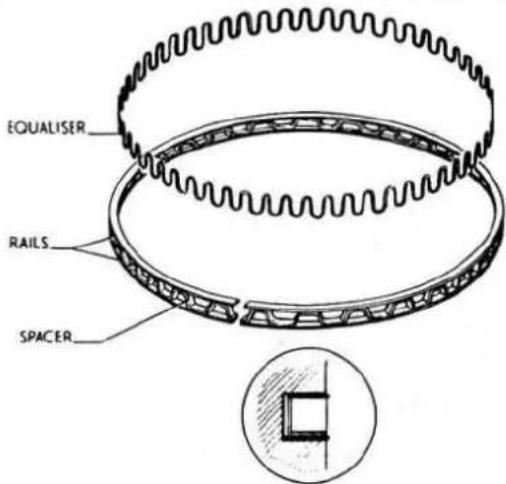
Fig.1.19. "Maxiflex" oil control ring

Fig.1.20. Method of modifying 2.4 litre piston
Fig. 1.21A Types of piston 2.4 litre

natural_image
Technical line drawing of a cylindrical mechanical component with internal structure and a central rod (no text or symbols)9:1 COMP:RATIO
natural_image
Line drawing of a cylindrical mechanical component with a central rod (no text or symbols)8:1 COMP:RATIO
natural_image
Technical line drawing of a piston-cylinder assembly (no text or labels)7:1 COMP:RATIO
Fig. 1.21B Types of piston 3.4 litre

Fig.1.22. Checking the piston ring gap

Fig.1.23. Identification marks on tapered periphery compression rings
case hardening of a cam, it is estimated that the engine from which this shaft was removed had done well over 100,000 miles. This type of fault is not as common as wear on the lobes. Preferably make a comparison with a new shaft although a good idea of their condition can be obtained by comparing one lobe with another and with those on the other camshaft.
Scoring on the bearing surfaces is a more likely fault to be found; it may be possible to remove slight score marks by gently rubbing down with very fine emery cloth or an oilstone, but this must not be overdone as undersize bearings are not supplied. Thus, if the scoring cannot be rectified, or if wear on the lobes is found, the shaft should be scrapped.
Examine the shell bearings for scoring, pitting and general signs of wear. It is advisable to fit new bearings if there is any doubt as to their condition.
Remember that the camshafts are not interchangeable, the inlet shaft has a dog drive at the rear for the revolution counter generator whereas the exhaust shaft is plugged at this end. Be careful to ensure, when checking valve clearances, that the correct camshaft for that particular bank of valves is indeed being used.
37 Valves and seats - examination and renovation
1 Examine the heads of the valves for pitting and burning, especially the exhaust valves.
2 If the valves appear fit to re-use after grinding to their seats in the cylinder head, scrape all carbon away and carefully clean the stem of the valve. Clean the valve guide in the cylinder head and fit the valve to its guide.
3 With the valve about three quarters of its way in the guide check it for sideways movement. If movement appears to be excessive, remove the valve and measure the diameter of the stem, this should not be less than 0.309". If the stem diameter is satisfactory it means that the valve guide is worn, note the condition when servicing the cylinder head. If no wear is present check the valve stem for truth by moving the valve up and down in its guide and at the same time rotating the valve, no restriction should be felt.
4 Valve grinding is easily carried out. Place the cylinder head upside down on a bench with a block of wood at each end to give clearance for the valve stems.
5 Smear a trace of coarse carborundum paste on the seat face and apply a suction grinding tool to the head of the valve. With a semirotary action, grind the valve to its seat, lifting the valve occasionally to redistribute the paste. When a dull matt even finish is produced on both the valve seat and the valve, then wipe off the paste and repeat the process with a fine paste, lifting and turning the valve as before. A light spring placed under the head of the valve will assist in the lifting operation. When a smooth unbroken ring or light grey matt is produced on both valve and valve seat faces, the grinding operation is complete. Be very careful during the grinding operation not to get the abrasive paste on the stem of the valve, do not handle the valve stem once you have started to use the abrasive because it will be transferred to the stem from the fingers and the result will be rapid wear of the valve guide. Trouble is often experienced with the suction tool not gripping the valve head, this can be overcome if the valve head and the tool are kept free of oil and grease at all times.
6 Do not overdo the grinding; if it becomes apparent that the valve will not bed down without excessive grinding the valve should be changed for a new one or the valve seat may require to be re-cut as explained later.
7 Thoroughly clean both the valve and the cylinder head when grinding is complete to remove any trace of carborundum, this can cause quite a bit of damage after first start up of the engine.
38 Inlet valve oil seals - general
To reduce the amount of oil being drawn down the inlet valve guides, "O" ring oil seals were introduced for late production Mk.2 models. These rings can be fitted to the whole range of 2.4,3,4 and 3.8 litre cars if desired.
From the introduction of the 240 and 340 models, oil seals were fitted to the inlet valve guides as shown in Fig.1.24. These guides may be fitted to existing cylinder heads but a complete set of parts as follows is required:-
| Inlet guide | 6 off |
| Valve collar | 6 off |
| Cotters | 12 off |
| Spring seat | 6 off |
| Circlip | 6 off |
When fitting the seals it is essential to ensure that the seal is seated in the groove machined in the top of the valve guide.

natural_image
Close-up of a metallic pipe joint or pipe fitting (no visible text or symbols)36.1. Unserviceable camshaft
natural_image
Dark, low-contrast image showing two curved light patterns against a dark background (no text or symbols)37.2. Clean valves

natural_image
Dark, low-contrast image of a small, indistinct object with no visible text or symbols37.5a. Valve grinding equipment
39 Valve springs - examination and test
After a considerable mileage some deterioration in the valve springs and consequent reduction in engine efficiency, must be expected. It is considered advisable, therefore, to test the springs when they are removed from the cylinder head to ensure that they are fit for use. It is felt that to measure the free length of a spring or to compare it with a new item is no test of its capacity. To avoid the need for special test equipment, the following method of test will meet requirements:-
1 Obtain a new inner and outer valve spring.
2 Place the new spring and the one to be tested end to end between the jaws of a vice or under a press with a flat metal plate interposed between the two springs.
3 Apply a load partly to compress the springs and measure their lengths whilst under load. If the old spring is obviously shorter than the new one it is a sign that deterioration has set in.
40 Tappets and valve adjusting pads - examination and renovation
Examine the bearing surface of the tappets which run on the camshaft. Any indentation on this surface or any cracks indicate serious wear and the tappet must be renewed. Thoroughly clean them out, removing all traces of sludge. It is unlikely that the sides of the tappets will be worn, but if they can be rocked in their guide in the cylinder head it should be established by measurement which item is at fault; details of dimensions are given in the Specifications at the beginning of this Chapter. The tappet should also be checked that it moves freely in the guide, the most likely cause of restriction is dirt but rectify as necessary.
Clean and examine the valve adjusting pads. After considerable mileage it is most probable that the pads will be indented, if this is found they should be replaced. Adjusting pads are available rising in 0.001" (0.03 mm) increments from 0.85" to 0.110" 2.16 to 2.79 mm) and are etched on the surface with the letter A to Z each letter indicating an increase in size of 0.001".
41 Cylinder head and bore - decarbonisation, examination and renovation
1 This operation can be carried out with the engine either in or out of the car. With the cylinder head off, carefully remove with a wire brush and blunt, plastic scraper, all traces of carbon deposits from the combustion spaces and the ports. Wash the combustion spaces clean with paraffin and scrape the cylinder head surface free of any foreign matter. Take care not to scratch or damage the face of the cylinder head in any way Do this work with the spark plugs, or an old set of plugs, fitted to the head to prevent hard carbon getting into the plug threads. If this happens and the carbon is not cleaned out there is risk of damaging the soft threads in the head when the plugs are screwed in.
2 Examine the face of the cylinder head for damage such as score marks, indentations or burning as depicted in the photograph adjacent. Damage of this type will prevent the head seating properly and will result in failure of the cylinder head gasket and burning of the head as shown or in water leak to the cylinders.
3 Examine the valve seat inserts, firstly for burning and pitting to the extent of preventing seating of the valves by grinding and secondly check the insert for security.
4 Burned or badly pitted valve seat inserts can be reclaimed by re-facing. Your local garage can probably do this work for you. Valve seat angles are:-
Inlet 2.4 litre Mk.1. 30°
All other models 45°
Exhaust All models 45°
5 The valve seat insert, valve guide and tappet guide are shrunk into the cylinder head and if either of these items are loose or damaged as to need replacement it is advisable to leave the job to a Jaguar agent having the necessary equipment and experience.
6 If a spark plug thread has been damaged to the extent of preventing correct fitment of the plug it is possible to reclaim the head by fitting an insert in the following manner:-
a) Refer to Fig.1.25.
b) Bore out the damaged thread to 0.75" (19.05 mm) diameter and tap ½" BSP.
c) Counterbore 57/64" (22.62 mm) diameter to accommodate the larger diameter of the insert.
d) Fit the screwed insert ensuring that it sits firmly at the bottom of the thread.

natural_image
Black-and-white photo of hands using a tool to work on a metal object, with no visible text or symbols.37.5b. Smear of carborundum paste on valve
natural_image
Close-up of a hand pressing down on an engine block (no visible text or symbols)37.5c. Grinding the valve to its seat

FIG.1.24. INLET VALVE OIL SEAL
1 Tappet
2 Valve collar
3 Cotters
4 Oil seal
5 Spring seat
6 Circlip
7 Inlet valve guide
e) Drill and ream a 1/8" (3.17 mm) diameter hole 3/16" (4.76 mm) deep between the side of the insert and the cylinder head. Drive in the locking pin and peen over the insert and locking pin. 7 Clean the pistons and the top of the cylinder bores. If the pistons are still in the bores then it is essential that great care is taken to ensure that no carbon gets into the bore for this will scratch the cylinder walls or cause damage to the pistons and rings. To stop it happening, first turn the crankshaft so that two of the pistons are at TDC. Place a clean non-fluffy rag into the other bores or seal them off with paper and masking tape. Seal off all other openings in the cylinder head and to the sump. 8 It is a matter of opinion as to how much carbon ought to be removed from the piston union. Some consider that a ring of carbon should be left around the edge of the pinion and on the
cylinder bore walls as an aid to keep oil consumption low. We feel that this is probably true for engines with worn bores, but with an engine in good condition the tendency should be to remove all trace of carbon. 9 If all traces of carbon are to be removed, press a little grease into the gap between the cylinder walls and the pistons that are to be worked on. With a blunt scraper carefully scrape away all carbon from the piston crown, taking care not to scratch the surface. Also scrape away carbon from the surrounding lip of the cylinder wall. When all carbon has been removed, scrape away the grease which will now be contaminated with carbon particles taking care not to press any into the bores. To retard carbon build up the piston crown can be polished with metal polish but be careful that the polish is not allowed to run into the bore.
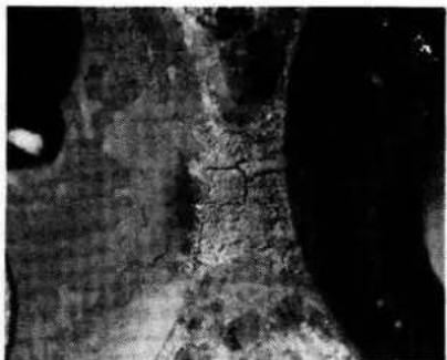
natural_image
Close-up of a textured surface with dark and light regions, possibly geological or material sample (no visible text or symbols)41.2. Burning and cracking of cylinder head

natural_image
Black-and-white photo of a handheld electric shaver with a handle and two small components below (no visible text or symbols)41.4a. Valve seat refacing equipment

natural_image
Close-up of an engine cylinder head assembly with visible bolts and mounting holes (no text or symbols)41.4b. Valve seat refacing stone

natural_image
Black-and-white photo of a large industrial machine with visible gears and shafts, no text or symbols present.41.4c. Drive for refacing stone
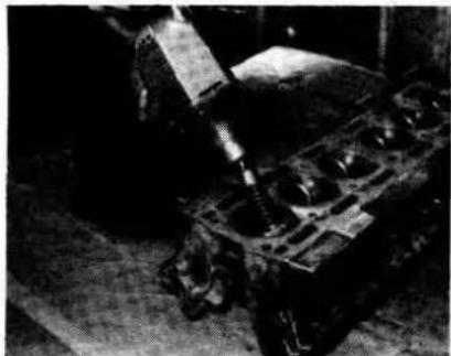
natural_image
Close-up of an engine cylinder being inserted into a mechanical housing (no visible text or symbols)41.4d. Refacing the valve seat

natural_image
Close-up of a mechanical component with a cylindrical end and flanged shaft (no visible text or symbols)47.1. Engine stabiliser - perished rubber

Fig.1.25. Fitting dimensions for spark plug inserts
e) Drill and ream a 1/8" (3.17 mm) diameter hole 3/16" (4.76 mm) deep between the side of the insert and the cylinder head.
Drive in the locking pin and peen over the insert and locking pin. 7 Clean the pistons and the top of the cylinder bores. If the pistons are still in the bores then it is essential that great care is taken to ensure that no carbon gets into the bore for this will scratch the cylinder walls or cause damage to the pistons and rings. To stop it happening, first turn the crankshaft so that two of the pistons are at TDC. Place a clean non-fluffy rag into the other bores or seal them off with paper and masking tape. Seal off all other openings in the cylinder head and to the sump.
8 It is a matter of opinion as to how much carbon ought to be removed from the piston union. Some consider that a ring of carbon should be left around the edge of the pinion and on the
cylinder bore walls as an aid to keep oil consumption low. We feel that this is probably true for engines with worn bores, but with an engine in good condition the tendency should be to remove all trace of carbon.
9 If all traces of carbon are to be removed, press a little grease into the gap between the cylinder walls and the pistons that are to be worked on. With a blunt scraper carefully scrape away all carbon from the piston crown, taking care not to scratch the surface. Also scrape away carbon from the surrounding lip of the cylinder wall. When all carbon has been removed, scrape away the grease which will now be contaminated with carbon particles taking care not to press any into the bores. To retard carbon build up the piston crown can be polished with metal polish but be careful that the polish is not allowed to run into the bore.

natural_image
Close-up of a textured surface with dark and light regions, possibly biological or geological (no visible text or symbols)41.2. Burning and cracking of cylinder head

natural_image
Black-and-white photo of a handheld device with a handle and spout, placed on a textured surface (no visible text or symbols)41.4a. Valve seat refacing equipment

natural_image
Close-up of a mechanical component with a spring and bolted base (no visible text or symbols)41.4b. Valve seat refacing stone

natural_image
Close-up of a mechanical component with no visible text or symbols41.4c. Drive for refacing stone

natural_image
Close-up of a mechanical engine block being inserted into a housing (no visible text or symbols)41.4d. Refacing the valve seat
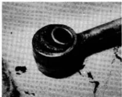
natural_image
Close-up of a mechanical component with a cylindrical end and flanged shaft (no visible text or symbols)47.1. Engine stabiliser - perished rubber

Fig.1.25. Fitting dimensions for spark plug inserts

natural_image
Technical line drawing of a mechanical assembly with gears and linkages (no text or symbols)Fig.1.26. Arrangement of timing gear

natural_image
Line drawing of a hand using a tool to adjust or install a mechanical component (no text or symbols present)Fig.1.29. Measuring the clearance between the inner and outer rotors

FIG.1.27. EXPLODED VIEW OF THE TIMING GEAR
1 Camshaft sprocket
2 Adjusting plate
3 Circlip
4 Guide pin
5 Star washer
6 Circlip
7 Timing gear front mounting bracket
8 Timing gear rear mounting bracket
9 Idler sprocket
10 Eccentric shaft
11 Plug
12 Adjustment plate
13 Plunger pin
14 Spring
15 Intermediate sprocket of top timing chain
16 Intermediate sprocket of lower timing chain
17 Key
18 Shaft
19 Circlip
20 Top timing chain
21 Damper for top timing chain (left hand)
22 Damper for top timing chain (right hand)
23 Distance piece
24 Intermediate damper (3.4 litre model only)
25 Bottom timing chain
26 Vibration damper
27 Hydraulic chain
tensioner
28 Shim
29 Filter gauze
30 Front timing cover
31 Gasket
32 Oil seal

FIG.1.28. EXPLODED VIEW OF THE OIL PUMP
1 Body
2 Rotor assembly
3 Cover
4 Setscrew
5 Setscrew
6 Spring washer
7 'O'ring
8 Drive shaft
9 Bush
10 Washer
11 Helical gear
12 Key
13 Nut
14 Locking washer
15 Shaft
16 Dowel bolt
17 Tab washer
18 Oil delivery pipe
19 Gasket
20 Oil suction pipe
21 Clip
22 Suction pipe supporting strut
23 Suction pipe supporting strut
24 Hood
25 Spring
26 Split pin

natural_image
Technical line drawing of a mechanical assembly with a hand operating a tool (no text or symbols present)Fig.1.30. Measuring the clearance between the outer rotor and the pump body

natural_image
Illustration of hands using a tool to adjust or install a mechanical component (no text or symbols visible)Fig.1.31. Checking endfloat of the rotors

FIG.1.32. EXPLODED VIEW OF THE BOTTOM TIMING CHAIN TENSIONER
A Plunger F End plug and tab washer
B Restraint cylinder G Body securing bolts and tab
C Spring washer
D Adjuster body H Gauze filter
E Backing plate I Shim

natural_image
Technical line drawing of a mechanical assembly with gears and springs (no text or symbols)Fig.1.33. Automatic fan belt tensioner

Fig.1.34. The engine stabiliser
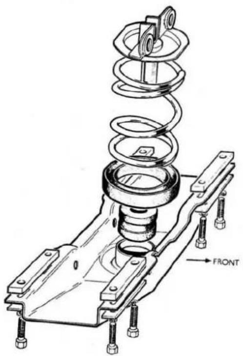
natural_image
Technical illustration of a mechanical spring assembly with mounting brackets and a labeled front view (no text or symbols beyond label)Fig.1.35. Exploded view of the rear engine mounting
are fitted with a r cleaners of the oil bath type as are early 3.4 and 3.8 litre models. Later production cars are fitted with paper element air cleaner.
51 Air cleaners - maintenance
The air cleaners should be serviced at overhaul of the engine irrespective of the mileage since the last routine servicing of the car.
Oil bath type:-
Unscrew the wing nut and remove the top cover, lift out the filter element and oil base. Wash the element by swishing up and down in a bowl of clean paraffin and allow to drain thoroughly. Empty the oil from the oil base and clean out the accumulated sludge. Fill the base with engine oil to the level indicated by the arrow, it is not necessary to re-oil the filter element as this is done automatically when the engine is run. Ensure that the top cover gasket is in good condition and reassemble the filter.
Paper element type:-
The only maintenance necessary is to replace the element and ensure that the air cleaner assembly in general is clean.
52 Engine reassembly - general
1 To ensure maximum life with minimum trouble from a rebuilt engine not only must every part be correctly assembled but everything must be spotlessly clean, all oilways must be clear, locking washers and spring washers must always be fitted where needed and all bearings and other working surfaces must be thoroughly lubricated during assembly in order to afford initial lubrication to parts when first starting the engine. Before assembly begins renew any bolts or studs the threads of which are in any way damaged, use new spring washers whenever possible and always use new self locking nuts. Never re-use a split pin despite the fact that the removed pin may appear to be in good condition. Use soft iron locking wire, or annealed copper wire, in places where locking wire is called for.
2 Apart from your normal tools, a good supply of non-fluffy rag, an oil can filled with engine oil, a set of new gaskets and a torque wrench should be collected together.
53 Crankshaft - replacement
Ensure that the crankcase is thoroughly clean and that all the oilways are clear. A thin twist drill is handy for cleaning them out. If possible blow them out with compressed air. Treat the crankshaft in the same fashion and then inject engine oil into the crankshaft oilways.
1 Fit the top half of the rear oil seal cover assembly at the rear of the cylinder block. Fit the top half of the oil seal. Later cars have a modified rear end cover incorporating an asbestos rope oil seal, Fig.1.36, in an annular groove in place of the older type cork seal. A modified crankshaft is also introduced with the new seal. Take the new asbestos seals and carefully tap them on the side face to narrow the section of the seal. Fit the seals to the housing and press into the groove using a hammer handle until the seal does not protrude from the ends of the housing. DO NOT cut the ends off the seal if they protrude from the housing but continue pressing into the groove until both ends are flush. Using a knife or similar tool, press all loose ends of asbestos into the ends of the grooves so that they will not be trapped between the two halves of the housing when assembled. Fit the asbestos seal to the bottom half of the cover assembly in the same manner as described above. The rear oil seal should now be "sized" and this is done with a special tool, Churchill Tool No.J.17 (Fig.1.37). The rear main bearing cap is fitted less shell bearings, to the cylinder block with the two halves of the seal assembly in position, tighten the cap to a torque of 83 lb.f.ft. Smear a small quantity of graphite grease around the inner surface of the seal and insert the tool. Ensure that the pilot end of the sizing bar enters the bore of the main bearing then press the bar inwards and rotate at the same time until the bar is fully home. Remove the bar by pulling and twisting at the same time. Remove the three Allen screws securing the oil seal housing to the cylinder block and remove the Allen screws securing the two halves of the seal and remove the rear main bearing. If this tool is not available there will be no option but to "work" the seal in on assembly of the crankshaft.
2 Clean the locations for the half main bearing shells in the crankcase and fit the half bearing shells.
3 Lay the crankshaft in the bearing shells.
4 Fit the bottom half of the oil return thread cover to the top half which is bolted to the cylinder block behind the rear main bearing.
5 Check the clearance between the oil return thread cover and the oil return thread on the crankshaft, this should be 0.0025" to 0.0055" (0.06 to 0.14 mm).
6 Fit the centre main bearing cap with a new thrust washer white metal side outwards, to the recess in each side of the cap. Tighten down the cap and check the crankshaft end float, this should be 0.004" to 0.006" (0.10 to 0.15 mm). The thrust washers are supplied in two sizes, standard and 0.004" (0.10 mm) oversize and should be selected to bring the end float within permissible limits. There is no objection to use of an oversize and a standard washer on the same shaft. The oversize washers are stamped + 0.004" (0.10 mm) on the steel face.
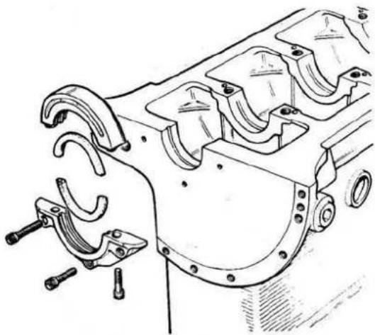
natural_image
Technical line drawing of an engine compartment with clamping tools (no text or labels)Fig.1.36. Rear oil seal - asbestos rope

natural_image
Illustration of hands using a tool to adjust or install a mechanical component (no text or symbols visible)Fig.1.37. Sizing the rear oil seal
7 Fit the main bearing caps and shells to the crankshaft. Ensure that the numbers stamped on the caps correspond with those stamped on the crankcase.
8 Fit the main bearing cap bolts and tab washers and tighten down to a torque of 83 lb.f.ft. the tab washers for the rear main bearing bolts are longer than the remainder and the plain ends should be tapped down around the bolt hole bosses.
9 Test the crankshaft for free rotation.
10 If there is no undue restriction to movement of the crank-shaft, knock up the tab washers to secure the bolts.
54 Piston and connecting rod - reassembly
The gudgeon pin must be replaced in the piston and then connecting rod in the same position as before removal.
1 If the gudgeon pin will not enter the piston, and it must not be forced, immerse the piston in a bath of hot oil for a few minutes.
2 Remove the piston from the oil and the gudgeon pin should now enter freely under finger pressure. Enter the pin in one half of the piston, engage the connecting rod (original way round) and push the gudgeon pin home.
3 Secure the gudgeon pin with a new circlip at each end.
55 Piston ring - replacement
1 Check that the piston ring grooves are thoroughly clean and that oilways are not blocked. Piston rings must always be fitted over the head of the piston and never from the bottom.
2 Refitment is the exact opposite procedure to removal, see Section 21.
3 Set all ring gaps at 90^ to each other.
4 As each ring is fitted, make sure that it is free in its groove.
5 When new rings are fitted to the piston the side clearance in the grooves should be checked on assembly. This clearance should be 0.001" to 0.003" (0.025 to 0.076 mm).
6 Ensure that the rings are fitted to their correct positions and are the correct way up (Fig.1.23).
56 Piston · replacement
Fit pistons complete with connecting rods, to the cylinder bores as follows:-
1 Turn the engine on its side.
2 Wipe the cylinder bores clean with a clean non-fluffy rag.
3 The pistons, complete with connecting rods, must be fitted to their respective bores from the top of the cylinder block. As each piston is inserted into the bore, make sure that it is the correct assembly for that bore by checking the number stamped on the connecting rod, (No.1 cylinder is the rear of the engine).
4 Ensure that the pistons are the correct way round in the cylinder, the piston crown is marked "Front" to aid reassembly (Fig.1.38).
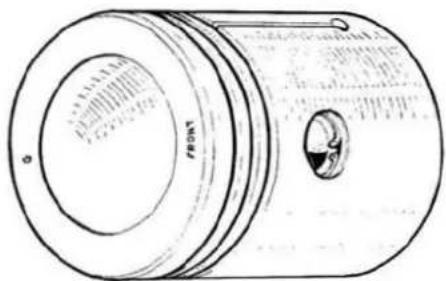
natural_image
Line drawing of a cylindrical mechanical component with a side view showing internal features (no text or symbols)Fig.1.38. Markings on the piston crown
5 Check that the piston ring gaps are at 90^ to each other.
6 Compress the piston rings in a clamp. Guide the piston into the bore until it reaches the ring compressor. Gently tap the piston into the bore with a wood or hide hammer.
7 Do not try to fit the pistons without a ring compressor as the chance of breaking a ring and scoring the bore is very high. If a compressor is not available then a suitable jubilee, clip is better than nothing but make sure that the clip is not tightened too much.
57 Connecting rod to crankshaft - reassembly
1 Wipe the connecting rod half of the big end bearing location and the underside of the shell bearing clean, and fit the shell bearing in position with its locating tongue engaged with the corresponding groove in the connecting rod. Always fit new shells.
2 Generously lubricate the crankpin journals with engine oil and turn the crankshaft to a handy position for the connecting rod to be drawn onto it and for the connecting rod cap to be fitted.
3 Fit the bearing shell to the connecting rod cap in the same manner as with the connecting rod itself.
4 Generously lubricate the shell bearing and offer up the cap to the connecting rod, ensure that the numbers are mating.
5 Fit new connecting rod bolts.
6 Fit the nuts (new self locking nuts if being used), tighten them to a torque of 37 lb.f.ft and fit new split pins if applicable.

natural_image
Technical line drawing of a washing machine component with no visible text or symbolsFig.1.39. Position of the distributor drive offset when No.6 piston is at T.D.C.
58 Crankshaft gear and sprocket - reassembly
1 Fit the Woodruff key and drive on the helical distributor drive gear with the widest part of the boss to the rear.
2 Fit the Woodruff key and drive on the crankshaft timing gear sprocket.
3 Fit the oil thrower, washer and distance piece.
4 Turn the engine until No's 1 and 6 pistons are at TDC.
59 Distributor and oil pump drive gear - reassembly
1 Fit the distributor drive shaft to the bush on the front face of the cylinder block with the offset slot in the top of the shaft positioned as shown in Fig.1.39.
2 Fit the thrust washer and drive gear to the shaft, noting that the gear is keyed to the shaft.
3 Fit the pegged tab washer with the peg in the keyway of the drive gear.
4 Engage the retaining nut, fully tighten it and then check the end float of the shaft which should be 0.004" to 0.006" (0.10 to 0.15 mm). If no clearance exists fit a new oil pump/distributor driving gear which will restore the clearance.
5 Secure with the tab washer when the clearance is satisfactory.
60 Oil pump and pipes - reassembly
1 Fit the coupling shaft between the squared end of the distributor drive shaft and the driving gear of the oil pump.
2 Secure the oil pump to the front main bearing cap by the three dowel bolts and tab washers. Check that there is appreciable end float of the short coupling shaft.
3 Fit the oil delivery pipe from the oil pump to the bottom face of the crankcase with a new 'O' ring and gasket.
4 Fit the suction pipe with a new 'O' ring at the oil pump end and secure to its clip on the main bracket cap.
61 Timing gear - assembly
1 Fit the eccentric shaft to the hole in the front mounting bracket.
2 Insert the spring and locking plunger for the serrated plate to the hole in the front mounting bracket.
3 Fit the serrated plate and secure with the shakeproof washer and nut.
4 Fit the idler sprocket (21 teeth) to the eccentric shaft.
5 Fit the two intermediate sprockets (20 and 28 teeth) to their shaft with the larger sprocket forward and press the shaft through the lower central hole in the rear mounting bracket. Secure with the circlip at the rear of the bracket. The intermediate sprockets of later models are a one piece casting.
6 Fit the top timing chain (longer chain) to the small intermediate sprocket and the bottom timing chain (shorter chain) to the large intermediate sprocket.
7 Loop the upper timing chain under the idler sprocket and offer up the front mounting bracket to the rear mounting bracket with the two chain dampers interposed between the brackets.
8 On models other than the 2.4 litre and 240, fit the intermediate damper to the bottom of the rear mounting bracket and secure with two screwdriver slotted screws and tab washers. Pass the four securing bolts through the holes in the brackets, the chain dampers and spacers noting that shakeproof washers are fitted under the bolt heads.
9 Secure the two mounting brackets together with four nuts and shakeproof washers.
62 Timing gear - reassembly to engine
1 Fit the lower timing chain damper and bracket to the front face of the cylinder block with two set bolts and locking plate.
2 Offer the timing gear assembly up to the cylinder block. Loop the bottom timing chain over the crankshaft sprocket and secure the mounting brackets to the front face of the cylinder block with the four long securing bolts and the two screwdriver slotted set screws which, on the 3.4 amd 3.8 litre and 340 models, also secure the intermediate timing chain damper bracket.
3 Do not fully tighten the two setscrews until the four long securing bolts are tight.
63 Timing chain tensioner - reassembly
1 Place the bottom timing chain tensioner, the backing plate
and the filter in position so that the spigot on the tensioner aligns with the hole in the cylinder block.
2 Fit the shims as may be necessary, between the backing plate and the cylinder to bring the rubber slipper central on the timing chain (Fig.1).
3 Fit the tab washer and the two securing bolts. Tighten the bolts and lock them with the tab washers.
4 It is important that the locking mechanism is not released until the adjuster has been finally mounted on the engine with the timing chain in position.
5 Remove the hexagon headed plug and tab washer from the end of the body.
6 Insert the Allen key into the hole until it registers in the end of the cylinder. Turn the key clockwise until the tensioner head moves forward under spring pressure against the chain. DO NOT attempt to force the tensioner head into the chain by external pressure.
7 Refit the plug and lock with the tab washer.
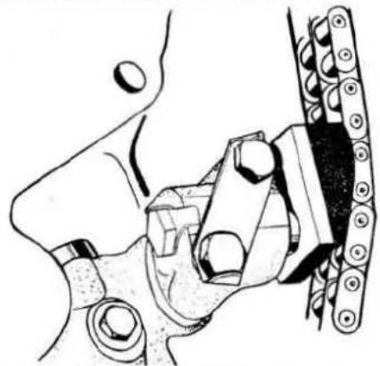
natural_image
Technical line drawing of a robotic arm joint with chains attached (no text or symbols)Fig.1.40. The bottom timing chain tensioner in position
64 Timing cover · refitting
1 Fit a new 'O' ring oil seal to the recess in the bottom face of the timing cover and ensure that the seal is well bedded in its groove.
2 Replace the dowels if you removed them during disassembly.
3 Smear the mating faces of the timing cover and the cylinder block with a good quality jointing compound and secure the timing cover to the front face of the cylinder block with the securing bolts.
4 Do not forget to fit the dynamo adjusting link and the distance piece, with the distance piece interposed between the link and the timing cover.
65 Oil sump - refitting
The oil sump may be refitted at this stage or, if it desired to use the base of the cylinder block on which to rest the engine for further assembly work, it may be left until later. However, to refit the sump:-
1 Clean the mating faces of the sump and the crankcase. Although not really necessary, they may be treated with jointing compound if desired.
2 Fit a new sump gasket to the bottom face of the crankcase.
3 Fit the oil seal to the recess in the rear main bearing cap.
4 Fit the sump to the crankcase and secure with the twenty-six set screws and the four nuts and washers. Remember that the short set screws goes at the right-hand front corner of the sump.
5 Fit the sump strainer in position using new gaskets.
66 Flywheel and clutch - refitting
1 Turn the engine upright.
2 Check the crankshaft flanges, the holes for the flywheel bolts and the dowels for freedom from burrs.
3 Check that No's 1 and 6 pistons are at TDC.
4 Fit the flywheel to the crankshaft flange so that the "B" stamped on the edge of the flywheel is approximately at BDC. This will ensure that the balance mark "B" is in line with the balance point of the crankshaft (this is a group of letters stamped on the crank throw just forward of the rear main journal).
5 Tap the two mushroom headed dowels into position.
6 Fit the locking plate and the flywheel securing set screws and tighten them to a torque of 67 lb.f.ft. Secure the screws with the locking tabs.
7 It is advisable to fit a new clutch driven plate now that the engine has been completely overhauled. Assemble the driven plate to the flywheel noting that one side of the plate is marked "Flywheel Side".
8 Centralise the driven plate by means of a dummy shaft which fits the splined bore of the driven plate and the spigot bush in the crankshaft. A constant pinion shaft may be used for this purpose.
9 Fit the clutch cover assembly so that the "B" stamped adjacent to one of the dowel holes coincides with the "B" stamped on the flywheel or that the marks you made, when separating the clutch from the flywheel, match up.
10 Secure the clutch assembly with the six set screws and new spring washers, tightening the screws a turn at a time by diagonal selection.
67 Oil filter - refitting
1 Ensure that the mating faces of the filter assembly and the cylinder block are clean.
2 Fit a new gasket between the filter assembly and the cylinder block and secure the assembly by the four set bolts.
3 Replace the flexible pipe between the oil filter and the sump.
68 Crankshaft damper and pulley - refitting
1 Fit the oil thrower followed by the distance piece.
2 Fit a Woodruff key to the crankshaft and assemble the split cone to the cranshaft with the widest end towards the timing cover.
3 Fit the damper to the cone and secure it with the flat washer, chamferred side outwards, and the bolt (nut in early models). Fit the locking plate over the bolt head (or the nut) and secure it with the two set screws.
4 Lock the set screws with the tabs at each end of the locking plate.
69 Distributor - refitting
1 Check that No.6 (front) piston is at TDC and check that the distributor drive shaft is in the position shown in Fig.1.39. It may be 180^ out in which case rotate the engine through a complete revolution to again bring No.6 piston to TDC. Again check the position of the slot.
2 Fit the cork seal to the recess at the top of the hole for the distributor.
3 Secure the distributor clamping plate to the cylinder, lock with the set screw. Slacken the clamping plate bolt.
4 Set the micrometer adjustment in the centre of the scale.
5 Enter the distributor into the cylinder block with the vacuum advance unit connection facing the cylinder block.
6 Rotate the rotor arm until the driving dog engages with the distributor drive shaft. In this condition the rotor arm should be in the approximate position of No.6 (front) cylinder segment in the distributor cap.
70 Cylinder head - reassembly
1 Turn the head upside down on the bench and rest it on
wooden blocks.
2 Generously lubricate the valve stems with engine oil and fit them in their correct positions.
3 Place the wooden block that was made up for valve removal, in position to retain the valves and invert the head allowing it to rest on the block on the bench.
4 Fit each valve with its valve seat.
5 Fit oil seals to the inlet valves ensuring that the seals of the 240 and 340 models are correctly engaged with the valve guide.
6 Fit the valve springs and caps.
7 Depress the valve springs and, with the help of an assistant, fit the cotters. It has been found that a tool as illustrated in Fig.1.41 makes compression of the springs much easier. It is essentially a tube with a part section cut away and its method of use is to apply the cut away part of the valve spring and to bear down on the spring unitl an assistant can enter the cotters through the cut away section. Care must be taken when compressing the springs, whatever method is used, to ensure that side loads are not put on the valve stem as in all probability they would be bent.
8 Fit cotter retaining circlips to the valve stems (if provided for).
9 Replace the tappets and valve adjusting pads in their correct positions.
71 Valve clearance adjustment
Valve clearance are :-
Inlet 0.004 inch (0.10 mm)
Exhaust 0.006 inch (0.15 mm)
Important
When checking the valve clearances the camshafts must be fitted one at a time as, if one camshaft is rotated when the other shaft is in position, fouling is likely to take place between the inlet and exhaust valves. When checking of the clearances of one set of valves is completed, the shaft must either be removed or the bearing cap bolts must be slackened to the extent of relieving all pressure on the valves.
1 Clean the location in the cylinder head for the camshaft bearing shells. Fit the half bearing shells to the head.
2 Clean the bearing location in the camshaft bearing caps and fit the half shell bearings.
3 Fit one camshaft to the cylinder head making sure that the correct shaft is being offered to the correct set of valves. Check the numbers on the caps to that shaft and the corresponding numbers on the cylinder head and fit the caps in their correct position. Fit the nuts and 'D' washers to the bearing studs.
4 Tighten down on the nuts to a torque of 9 lb.f.ft.
5 Rotate the camshaft to bring the back of a cam to the valve tappet. Measure, and record, the clearance between the cam and the tappet. Repeat for all the valves in that bank.
6 Adjusting pads are available rising in 0.001" (0.03 mm) sizes from 0.85" to 0.110" (2.16 to 2.79 mm) and are etched on the surface with the letter A to Z each letter indicating an increase in size of 0.001" (0.03 mm).
7 Should any valve clearance require adjustment, remove the camshaft, the tappet and adjusting pad.
8 Observe the letter stamped on the adjusting pad and should the recorded clearance for this valve have shown, say, 0.002" (0.05 mm) in excess of the correct value, select a new adjusting pad bearing a letter two lower than the original pad.
9 After all the adjusting pads have been changed as may be required, reassemble the camshaft and carry out a final check to ensure that the clearances are indeed correct. Remove the camshaft or slacken all the nuts to relieve all pressure on the valves.
10 Repeat the foregoing to check the valve clearances for the other set of valves. When satisfied that the clearances are correct, check the security of the nuts and turn the camshaft so that the square slot in the shaft at the rear of the front bearing is at 90° to the camshaft cover face (refer to Fig.1.42).
11 Fit the other camshaft and position it so that its slot is also at 90° to the camshaft cover face. Fit the nuts to the studs and
58

Fig.1.41. Tool for compressing valve springs

natural_image
Black-and-white photo of two rusted metal tools on a textured surface (no visible text or symbols)70.7a. Tools used for removing and replacing valve springs

natural_image
Close-up of mechanical components with no visible text or symbols70.7b. Replacing the valve cotters
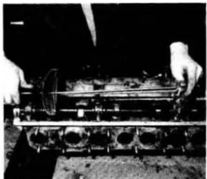
natural_image
Close-up of hands operating a mechanical engine component (no visible text or symbols)71.4. Tighten camshaft bearing caps to a torque of 9 lbs.f.ft

natural_image
Close-up of a hand using a tool to adjust or install mechanical parts on a metal workpiece (no visible text or symbols)71.5. Checking tappet clearance

natural_image
Close-up of an engine cylinder head with visible internal components (no text or symbols)72.3a. Fit a new cylinder head gasket

natural_image
Close-up of a mechanical component with circular features and a central oval (no visible text or symbols)72.3b. Marking on cylinder head gasket

natural_image
Black-and-white photo of a person standing on a textured surface, no visible text or symbols72.4. The valve timing gauge
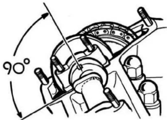
Fig.1.42. Position of slot for assembly of camshaft
tighten down (torque 9 lb.f.ft.)
12 From this point onwards the camshafts must not be rotated independently of each other.
72 Cylinder head - refitting
1 Ensure that the top face of the cylinder block and the mating face of the cylinder head are thoroughly clean.
2 Check that No.6 piston is at TDC with the distributor rotor arm opposite No.6 cylinder segment.
3 Fit a new cylinder head gasket to the cylinder block and make sure that it is seated right down on the top of the block, and that the side marked 'TOP' is uppermost.
4 Check that the slot in the camshafts are at 90° to the camshaft cover face and accurately position them by engaging the valve timing gauge. The valve timing gauge passes over the camshaft and rests on each side of the camshaft cover face and at the same time a projection engages in the camshaft slot and ensures that the slot is perpendicular, Fig.1.43 illustrates the gauge in position. It may be possible for you to borrow a gauge and apart from this no suitable alternative can be proposed for the accurate position required for the camshafts in actual valve timing (see Section 73).
5 Fit the cylinder head, note that the second cylinder head stud from the front on the left hand side is a dowel stud.
6 Fit plain washers to the 3rd and 6th stud on the right hand side, the sparking plug lead carrier will be fitted to these studs later. Fit plain washers also to the two front stud positions and 'D' washers to the remainder of the studs.
7 Fit the fourteen dome nuts and the nuts at the front of the head and screw down finger tight.
8 Using a torque wrench, tighten down the nuts a turn at a time, in the order shown in Fig.1.8, to a torque of 54 lb.f.ft.

natural_image
Close-up of mechanical components with no visible text or symbols72.8. Tighten cylinder head nuts to a torque of 54 lb.f.ft
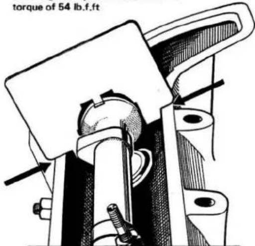
Fig.1.43. The valve timing gauge in position
73 Valve timing
1 It is important to tension the top timing chain before attempting to check or set the valve timing. If the engine is in course of reassembly, fit the sprockets to their respective camshafts. Tighten down on the securing set screws but do not lock them at this stage.
2 By access through the breather aperture in the front of the cylinder head, slacken the locknut securing the serrated plate (see Fig.1.44), press the locking plunger inwards and rotate the serrated plate, by engaging a tool (a pair of round nosed pliers will be found suitable), in an anti-clockwise direction. Turn the engine each way slightly and check the chain tension. When tensioned correctly there should be slight flexibility on both outer sides below the camshaft sprockets, the chain should not be dead tight. Release the locking plunger to the serrated plate and securely tighten the plate locking nut.
3 Remove the locking wire (if applicable) from the setscrews securing the camshaft sprockets, it may be necessary to rotate the engine to gain access to both the screws.
4 By reference to the timing marks on the crankshaft damper, or in early cars the timing marks on the flywheel (see Fig.1.45), turn the engine until No.6 piston is exactly on Top Dead Centre with the distributor rotor arm opposite No. 6 segment.
5 Tap the camshaft sprockets off the flanges of the camshafts and make provision for them not to fall into the sump.
6 Accurately position the camshafts with the valve timing gauge (refer to paragraph 4 of Section 72) so that the slots are perpendicular to the face of the camshaft cover.
7 Refer to Fig.1.46. Withdraw the circlips retaining the adjuster plates to the camshaft sprockets and press the adjusting plates forward until the serrations disengage. Replace the sprockets on the flanges of the camshafts and align the two holes in the adjuster plate with the two tapped holes in each camshaft flange.

natural_image
Close-up of a hand holding a small mechanical component, possibly a tool or tool, with no visible text or symbols.73.2 Tool for rotating serrated plate

natural_image
Technical line drawing of a mechanical component with mounting flanges and central hub (no text or symbols)Fig.1.44. The serrated plate for adjustment of the top timing chain
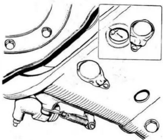
natural_image
Illustration of a hand using a tool to adjust or install a mechanical component, with inset showing two circular components (no text or symbols present)
natural_image
Technical line drawing of a mechanical assembly with no visible text or symbols
natural_image
Technical line drawing of a mechanical assembly with no visible text or symbols

Fig. 1.45. Top dead centre marks, alternative positions (section 73.4)

natural_image
Technical line drawing of a mechanical component with three views: a curved hook, a flanged wheel, and a toroidal gear (no text or symbols)Fig.1.46. The camshaft sprocket assembly

Fig.1.47. Valve timing diagrams
Engage the serrations of the adjuster plate with the serrations in the sprockets. It is important that the holes are in exact alignment, otherwise when the setscrews are fitted, the camshafts will be moved out of position.
8 If difficulty is experienced in aligning the holes correctly the adjuster plates should be turned through 180° and this, due to their construction, will facilitate alignment.
9 Refit the circlips to the sprockets and secure the sprockets with the setscrews turning the engine as necessary after one setscrew has been fitted to give access to the other screw.
10 Turn the engine and repeat the above operations to check the correctness of the valve timing.
11 If the timing is satisfactory, lock the setscrews with locking wire. It is advisable to put some rags in the front cover aperture if you have to cut off the ends of the locking wire to prevent them falling into the sump.
12 Place new gaskets on the camshaft cover faces. Refit the camshaft covers and tighten down on the dome nuts.
74 Inlet manifold - refitting
1 Clean the mating faces of the inlet manifold and the cylinder block.
2 Place a new gasket over the inlet manifold studs on the cylinder block. Offer up the inlet manifold and tighten down evenly on the nuts.
3 Fit the thermostat and, using a new gasket, refit the thermostat cover.
4 Refit the fuel pipes to the underside of the manifold. Be careful not to cross thread the nuts.
75 Cylinder head oil feed pipe - refitting
Fit the cylinder head oil feed pipe from the tapped hole in the main oil gallery to the two tapped holes in the cylinder head. Secure the pipe with the three banjo bolts fitting a new copper washer on both sides of each banjo.
76 Water pump - refitting
1 Clean the mating faces of the water pump and the timing cover. They may be treated with a sealing compound if desired.
2 Fit a new gasket over the studs in the timing cover.
3 Fit the water pump to the timing cover and secure with the
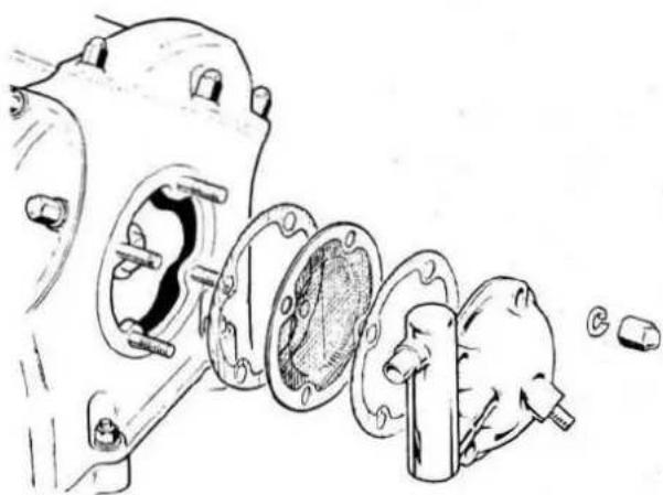
natural_image
Technical line drawing of a mechanical assembly showing internal components and housing (no text or labels)Fig.1.48. Engine breather - gauze type
six bolts and the three nuts and spring washers to the studs. Tighten down evenly all round.
4 Fit the hose from the pump to the thermostat housing and tighten the clips.
77 Engine breather assembly - refitting
1 Clean the mating faces of the engine breather and of its location at the front of the cylinder block.
2 Fit a new cork washer over the studs in the cylinder head.
3 Fit the gauze filter, or the perforated plate in early cars, over the studs followed by another cork washer.
4 Fit the breather assembly and secure with the four dome nuts.
78 Gearbox - refitting
1 Offer up the gearbox to the crankcase and make sure that it is fully home.
2 Replace the set bolts and nuts securing the clutch housing to the engine starting at the top and working downwards. The gearbox assembly must be supported during this operation to avoid straining the clutch driven plate and the constant pinion shaft.
3 Tilt the engine to give access to the flywheel dust cover and secure the cover with the four nuts and bolts.
4 Replace the starter and its curved metal rod and secure with the two nuts and bolts.
79 Final assembly
1 Refit the automatic fan belt tensioner where applicable (later model 3.4 and 3.8 litre cars, the 240 and 340 models).
2 Fit a new 'O' sealing ring to the revolution counter generator, assemble the generator to its drive in the rear of the inlet camshaft and secure in position with the plate washer, three socket head screws and locking washers.
3 The engine stabiliser should be fitted to the engine at this stage as assembly after the engine is installed will not be an easy task. Engage the stabiliser with its mounting and press the securing bolt through the mounting brackets and the rubber of the stabiliser. Secure the bolt with its self locking nut. Screw the flanged washer ('D' in Fig.1.34) well down the stem of the stabiliser so that it will not cause any obstruction when moving the engine into position in the car.
4 The engine is now ready to be replaced in the car.
80 Engine replacement
The engine and gearbox could be replaced by one man and a suitable hoist but the job will be made much easier, and safer, with the help of an assistant. Generally replacement is the reverse sequence to removal.
1 Ensure that all leads, cables etc., are tucked out of the way in the engine bay. It is easy to trap one and cause much additional work when the engine is replaced.
2 Fit the lifting plate to the engine in the manner described in Section 5 paragraph 54.
3 Hoist the engine into position in the engine bay, fit the rear mounting and raise the rear of the engine to bring the mounting into position on the underbody of the car. During this operation ensure that the engine stabiliser enters its mounting bracket on the front bulkhead. Ensure that the packing washers are correctly positioned to the rear mounting bracket.
4 Secure the engine at each front mounting.
5 Replace parts and make all connections generally in the
reverse order to that set out in Section 5.
6 Check that all drain taps have been closed and that the sump and gearbox drain plugs are tight.
7 Refill the cooling system and the engine and gearbox with the recommended type of lubricating oil.
8 Carefully check all water unions for leaks, tighten up as necessary.
9 Refer to Fig.1.34. Adjust the engine stabiliser by screwing the lower flanged washer (D) up the pin until the flange contacts the bottom of the stabiliser rubber mounting (C). The washer is slotted on its upper face and can be screwed up the pin by engaging a thin bladed screwdriver in the slot through the centre hole of the rubber mounting. Fit the upper flanged washer (B) and tighten down with the locking nut (A). Do not overtighten the lower flanged washer as this can cause vibration and/or fouling of the gearbox in its cowl due to the engine having been pulled up on its mountings.
81 Engine - initial start up after overhaul and major repair
Refer to Chapter 3 and follow the instructions for initial setting of the carburettors, and follow the instructions in Chapter 4 for timing of the ignition. Make sure that the battery is fully charged and that all lubricants and fuels are replenished. Switch on the ignition and allow the petrol pump time to fill the carburettor float chambers.
Start the engine, as soon as it fires and runs, keep it going at a fast tickover only (no faster). Watch the oil pressure gauge, after a very short wait, whilst the oil filter is being filled, it should register around 40 lbs per sq.in. If, after about 30 seconds, no oil pressure is registered, switch off the engine and investigate the cause; it may be that you have not fully tightened a union or the filter canister is not correctly seated on the rubber sealing ring in the head of the filter.
Bring the engine up to its normal working temperature, as it warms up there will be odd smells and some smoke from parts getting hot and burning off oil deposits. Look round carefully for water and oil leaks.
When the engine running temperature has been reached adjust the carburettors as described in Chapter 3.
Stop the engine and wait a few minutes to see if there are any water or oil leaks.
Before road testing the car it is advisable to have an assistant listening to the brake servo exhaust, run the engine for a few minutes and then operate the foot brake. If the brake servo connections are satisfactory the exhaust from the servo will be plainly heard.
Road test the car to check that the timing is correct and is giving the necessary smoothness and power. Do not race the engine. If new bearings or pistons or rings have been fitted, it should be treated as a new engine and run in at reduced revolutions for the first 500 miles.
Chapter 2 Cooling system
Contents
| General description ... ... ... ... ... ... ... 1 | Water pump - removal and refitment ... ... ... ... ... 11 |
| Cooling system - draining ... ... ... ... ... ... 2 | Water pump - dismantling and overhaul ... ... ... ... 12 |
| Cooling system - flushing ... ... ... ... ... ... 3 | Temperature gauge and thermal transmitter - general ... 13 |
| Cooling system - filling ... ... ... ... ... ... 4 | Water temperature gauge Mk 1 models - testing, removal and refitting ... ... ... ... ... ... ... 14 |
| Radiator - removal and refitting ... ... ... ... ... 5 | Water temperature gauge Mk 2, 240 and 340 models - testing, removing and refitting ... ... ... ... ... ... 15 |
| Radiator inspection and cleaning ... ... ... ... ... 6 | Anti-freeze mixture ... ... ... ... ... ... 16 |
| Thermostat - removal, testing and replacement ... ... ... 7 | Fault diagnosis ... ... ... ... ... ... ... 17 |
| Fan - removal and refitting ... ... ... ... ... 8 | |
| Fan belt - removal and replacement ... ... ... ... ... 9 | |
| Fan belt - adjustment ... ... ... ... ... ... 10 |
Specifications
| Type ... ... ... ... ... ... ... ... ... | Pressurised system thermostatically controlled | |
| 2.4 litre/240 | 3.4, 3.8 litre/340 | |
| Total capacity of coolant including heater ... ... | 20 pints(11.40 litres) | 22 pints(12.55 litres) |
| Water pump - type ... ... ... ... ... ... | Centrifugal | |
| drive ... ... ... ... ... ... ... | Fan belt | |
| Fan belt - andle of 'V' ... ... ... ... ... ... | 40^ (36^ for Mk 1 models) | |
| Fan - number of blades ... ... ... ... ... ... | 12 | 12 (2.4 litre early cars - 4) |
| Fan to engine speed ratio ... ... ... ... ... ... | 0.9:1 | |
| Cooling system control ... ... ... ... ... ... | Thermostat | |
| Thermostat data : | ||
| Jaguar Part No. | Model/Engine No. | Temperature. Degrees C |
| C.3731/1 | 2.4 Mk 1 BB.1001 - BB.999andBC.1001 - BC.44073.4 Mk 1 KE.1001 - KE.5732 | 73 - 85/90 |
| C.13944 | CommencingBC.4408 (2.4 Mk 1)KE.5733 (3.4 Mk 1)All Mk 2 models and 3.8 litre | 74 - 86/91 |
| C.13944/1 | As above | 80 - 92/97 |
| C.27650 | Mk 2 models and 3.8 litre | 85 opening |
| C.27650/1 | As above | 93 opening |
| C.28067 | 240 and 340 | 74 - 85 |
| C.28067/1 | 240 and 340 | 82 - 96 |
Note:- When ordering a replacement thermostat it is advisable to quote the model and engine number as there is no guarantee that the above quoted part numbers will not be superseded.
| Radiator type | ... | ... | ... | ... | ... | ... |
| Radiator cap | ||||||
| Make and type | ... | ... | ... | ... | ... | ... |
| Release pressure | ... | ... | ... | ... | ... | ... |
| Release depression | ... | ... | ... | ... | ... | ... |
| Radiator flow figures ; water at 62°F (17°C) | ||||||
1 General description
Water circulation is assisted by an impeller type pump mounted on the front cover of the engine. The system is pressurised and is thermostatically controlled. It is pressurised by means of the radiator filler cap which incorporates a pressure relief valve designed to hold a pressure of up to 4lbs per sq in above atmospheric pressure; when the pressure rises above 4 lbs the spring loaded valve lifts off its seat and the excess pressure escapes via the overflow pipe. As the water cools down again a small valve, incorporated in the centre of the pressure valve unit, opens and restores atmospheric pressure if a depression is caused by the cooling of the water. The object of pressurising the system is that the boiling point of the coolant is raised by approximately six degrees and thus the risk of loss of coolant by boiling is reduced. The thermostat cuts off the coolant in the engine from that in the radiator until such time as the engine coolant reaches a certain temperature at which, determined by the thermostat setting, the thermostat opens and allows free passage of the coolant round the system. The purpose of the thermostat is to ensure that the engine is brought quickly to its most efficient operating temperature.
Water is circulated from the base of the radiator block via the water pump through the cylinder block and the cylinder head passages and is returned to the radiator header tank by way of the inlet manifold water rail (and thermostat). The water is cooled in its passage from the radiator header tank, through the radiator matrix to the base of the radiator block. Cooling is enhanced by a fan, mounted on the spindle of the water pump, which draws in air through the radiator block; early model cars were fitted with four bladed fans but all later models have twelve blades to provide more efficient cooling. The capacity of the radiator is approximately 6% pints (3.85 litres) of coolant.
The cooling system of the 240 and 340 cars is basically similar to the other models but, because of the revised inlet manifold of those cars, the thermostat is contained in a separate housing interposed between the manifold and the water outlet elbow. In addition an air bleed valve is positioned in the air vent aperture in the water outlet elbow to ensure that any air in the system is expelled to the radiator filler neck above the coolant level.
2 Cooling system - draining
The cooling system is provided with two drain taps. One a remote controlled drain tap located in the base of the radiator block and operated by a rod positioned at the left hand side of the header tank. The other, a cylinder block drain tap, is mounted on the rear left hand side of the cylinder block below the exhaust manifold.
With the car on level ground drain the system as follows:-
1 If possible, wait until the engine is cold. Unscrew and remove the radiator filler cap. REMEMBER the system is pressurised so DO NOT remove the cap whilst the engine is hot without taking precautions to prevent injury to yourself by the hot liquid which will be thrown out when pressure is released.
2 Place the heater control at HOT.
Film - 10 fins/inch (4 fins/cm)
| A.C. - relief valve | ||
| 4 lbs per sq inch | ||
| 1⁄2 lb | ||
| lbs per sq. in | galls/min: | Litres/min |
| 1 | 15.5 | 70.5 |
| 1.5 | 19 | 86.5 |
| 2 | 22 | 100.0 |
| 2.5 | 24.5 | 111.5 |
| 3 | 26.5 | 120.0 |
| 3.5 | 29.0 | 131.8 |
| 4 | 31.0 | 140.9 |
3 Open the remote control drain tap by moving the angled arm of the rod upwards the rear of the car (it may happen that the control rod has been assembled 180° out, in which case move the arm towards the front of the car). It sometimes happens that this tap becomes blocked with sludge accumulated at the bottom of the radiator and it may be possible to clear the tap by poking out with a piece of wire but if this is not successful, the tap will have to be removed. Remove the split pin securing the forked end of the rod to the tap and push upwards out of the way. Unscrew the tap by use of a spanner on the spanner flats. Be careful not to be scalded by the coolant if the engine is at normal operating temperature.
4 Open the cylinder block drain tap. This tap may also be blocked by scale and sludge in the cylinder block passages. It may be possible to also clear this tap with a piece of wire but it will, in all probability, have to be removed. Access to the tap for removal is easier from below the engine; unscrew the tap by using a spanner on the spanner flats. Again take precautions if the engine is hot.
Note if it is desired to retain the coolant, the radiator drain tap only should be opened. Open the cylinder block drain tap when the radiator tap has stopped running to ensure that the cylinder block is clear.

Fig.2.1. The remote control drain tap

natural_image
Technical line drawing of a mechanical component with a wrench and gear assembly (no text or symbols)Fig.2.2. The cylinder block drain tap
3 Cooling system - flushing
1 After prolonged use it is possible that the cooling system will gradually deteriorate in efficiency as the radiator becomes choked with rust scale, deposits from the water and other sediment. The system of deterioration is boiling of the engine or high operating temperatures which cannot be accounted for by fuel or ignition or other faults. To clean the system out, remove the filler cap, the bottom hose to the radiator, the cylinder block drain tap and the thermostat (see Section 7). Replace the thermostat housing. Leave a hose running in the radiator filling hole for about fifteen minutes.
2 Reconnect the bottom hose, refit the cylinder block drain tap and the thermostat. Refill the system and at the same time add a proprietary cleaning compound. Beware of splashing the compound on paintwork as this could cause damage. The engine must now be run for the period prescribed by the makers of the compound and this should loosen all sediment and sludge which can now be removed by draining. Thoroughly flush out the system and refill with soft water.
3 In very bad cases it may be necessary to reverse flush the radiator. This can be done with the radiator in position by placing a hose in the bottom hose union of the radiator. Water under pressure is forced through the orifice and out of the filler cap hole.
4 The hose is then removed and is now placed in the filler cap hole and the radiator washed out as described above.
4 Cooling system - filling
1 Place the heater control in the HOT position.
2 Close both drain taps and fill the system slowly to ensure that no airlocks develop. It is recommended that rain water is used in the system.
3 Fill the radiator to the level of the filler hole and check that surplus water runs out of the overflow pipe. Refit the radiator cap.
4 Start the engine and run at a fast idle speed for a few minutes.
5 Stop the engine and top up the radiator as necessary.
6 Check the system for leaks at drain plugs and hoses. Rectify as necessary.
5 Radiator - removal and refitting
1 Drain the cooling system as described in Section 2.
2 Disconnect the top and bottom water hoses.
3 Remove the four nuts securing the cooling fan cowl, note that the top left hand nut also secures the bracket for the remote control drain tap rod. Remove the cowl and hang it over the fan clear of the radiator.
4 Remove the split pin securing the remote control rod to the radiator drain tap and disengage the rod.
5 On cars with automatic transmission, disconnect the two transmission oil cooler pipes running from the bracket mounted on the engine. Place a tray beneath the radiator to catch escaping oil and blank off the two unions. Blank off the pipe unions and tie the pipes up to the engine to prevent the oil syphoning out of the transmission unit.
6 Remove the set screws which attach the sides of the radiator to the body.
7 Remove the two securing nuts at the bottom mounting. Have an assistant to carefully raise the radiator; note the number of plain and rubber washers fitted to each bottom mounting bolt. 8 Carefully lift out the radiator and at the same time ensure that the matrix does not foul the fan blades. If any restriction is felt when lifting the radiator, check that it is not being caused by the tap fouling the bottom of the cowl.
Important: Always store the radiator block in an upright position to guard against any sediment which may have collected in the bottom tank passing into the small core passages and subsequently causing a blockage. Remove the cowl.
9 Refitting is the reverse sequence to the above. Ensure that the correct number of washers are fitted to each of the bottom bolts.
10 Refill the system as described in Section 4.
11 On those cars with automatic transmission, check the fluid level in the transmission unit.

natural_image
Black-and-white photo of a person in a suit, possibly a military or industrial setting, with no visible text or symbols.5.3. Remove nuts securing cooling fan cowl

natural_image
Close-up of a mechanical component with a metallic rod inserted, showing no visible text or symbols.5.4. Remove remote control rod
6 Radiator - inspection and cleaning
1 Examine the top and bottom tanks for damage and leaking especially at the seams. Any leaks or possible weakness can be repaired with a compound such as Cataloy, the application of heat to the radiator, soldering for instance, is not recommended for the home enthusiast as this may result in breaking other soldered seams.
2 Examine the core for damage and corrosion. It may be possible to repair leaks from physical damage using Catalogy but if leaks are present due to corrosion it is best to replace the radiator as any repair that is made will only effect a temporary remedy. A replacement radiator can be obtained from your Jaguar agent on an exchange basis.
3 When the radiator is out of the car it is advantageous to reverse flush it in the manner described in Section 3. Clean the outside of the radiator by hosing down the matrix with a strong jet of water to clean away road dirt, dead flies etc:
4 Inspect the radiator hoses for cracks, internal and external perishing and cuts on the exterior from the hose clips. Change the hose if its condition is at all doubtful. Examine the hose clips for rust and damage and replace as necessary.
7 Thermostat - removal, testing and replacement
The thermostat is located on the top right hand water rail forward of the carburettors and is housed under an elbow connection with a domed head.
1 To remove the thermostat first partly drain the system, approx: 8 pints will be sufficient, collect the coolant in a suitable container if it is desired to re-use.
2 Slacken the clip securing the hose to the thermostat housing and remove the hose.
3 Remove the two nuts securing the elbow pipe to the housing and remove the pipe and gasket. The thermostat will now be visible in its housing.
4 Remove the thermostat from its housing, it is possible that it will be securely held in place by scale in which case careful levering with a small screwdriver will be necessary but do not lever on the circular valve which will be seen on the top face of the thermostat.
5 Clean the thermostat and ensure that the small hole on the valve is clear. If the valve is open it indicates that the thermostat is unserviceable and should be replaced with a new item of similar operating temperature, this figure will be seen on the top side of the thermostat.
6 If correct operation of the thermostat is in doubt test it by immersing it together with a 0 - 100°C thermometer in a container of cold water. Heat the water, keeping it stirred, and observe if the operation of the valve is in close agreement to the temperature marked on the body of the thermostat. Allow the water to cool down and check that the valve closes correctly.
7 If the operation is satisfactory, the thermostat may be refitted in the reverse order to the above. A new gasket should be fitted between the elbow pipe and the thermostat housing.

natural_image
Black-and-white photo of a mechanical device with visible components and no readable text or symbols5.7. Remove bottom securing nuts to radiator
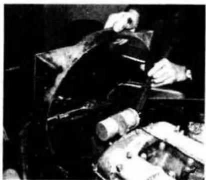
natural_image
Close-up of hands operating a mechanical device with rollers and gears (no visible text or symbols)5.8a. Remove cowl
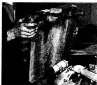
natural_image
Black-and-white photo of hands operating machinery with no visible text or symbols5.8b. Lift out radiator

natural_image
Close-up of a mechanical component with a circular opening, possibly a valve or pump (no visible text or symbols)7.3. Remove elbow pipe

natural_image
Close-up of a mechanical component with no visible text or symbols7.5. Valve open. Thermostat unserviceable
8 Fan - removal and refitting
The twelve bladed fan is made in one piece and static balance is adjusted by balance pieces the position of which is marked at initial assembly with a centre punch and a small hole is also drilled through them, the fan and the hub to ensure their correct location one to the other on reassembly to preserve the balance, see Fig.2.4.
1 Remove the radiator as described in Section 5.
2 Slacken the dynamo bolts and push the dynamo towards the engine. Press against the spring on the fan belt tensioner (if fitted) to relieve tension on the belt. Then work the belt off the dynamo hub (DO NOT use a lever on it). Remove the belt.
3 Examine the position of the balance pieces and locating
marks, make your own marks for reassembly if you have any doubt.
4 Remove the fan from the hub by undoing the four set screws.
5 If it is necessary to replace any part of the fan assembly it must be rebalanced. Static balancing is effected by varying the position of the balance pieces which are retained by set screws securing the fan to the hub. These should be arranged so that the fan remains at rest in any position when set upon its hub on a ring as shown in Fig.2.5. After rebalancing, the ends of the balance pieces and the fan should be marked with a centre punch and a small hole drilled through the balance pieces, the hub and the fan. The old hole should be filled in with solder.
7 Refitting is the reverse of the procedures set out in paragraphs 1 - 5 above attention being paid to the necessity to preserve balance of the assembly.
8 Adjust the fan belt as described in Section 10.
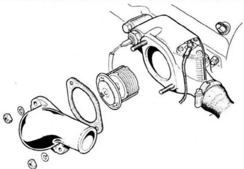
natural_image
Technical illustration of a mechanical assembly with exploded view of internal components (no text or symbols)Fig.2.3. Exploded view of thermostat and housing (3.4 litre Mk.2 illustrated)

natural_image
Technical line drawing of a mechanical component with multiple blades and central hub (no text or symbols)Fig.2.4. Fan showing balance pieces and location hole
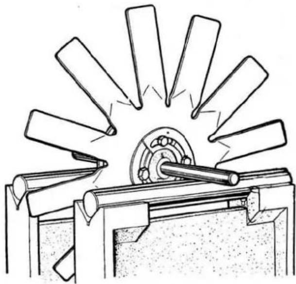
natural_image
Technical line drawing of a mechanical device with multiple blades radiating from a central shaft (no text or symbols)Fig.2.5. Balancing the fan assembly

natural_image
Black-and-white photo of a dark, textured surface with indistinct shapes and no visible text or symbols8.2. Work belt off dynamo hub
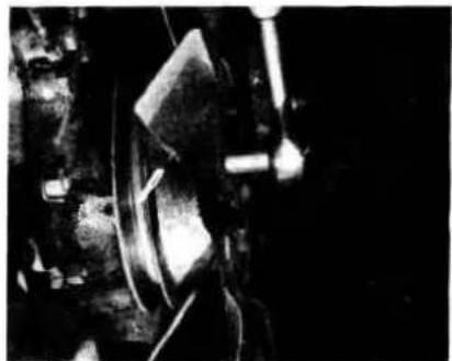
natural_image
Close-up of a mechanical component with wires and a metallic tool (no visible text or symbols)8.4a. Remove setscrews securing fan

natural_image
Close-up of a hand operating a mechanical device with visible gears and shafts (no text or symbols)8.4b. Remove fan
9 Fan belt - removal and replacement
1 Loosen the dynamo mounting bolts and push the dynamo towards the engine.
2 If an automatic belt tensioner is fitted (see Fig.1.33), press against the spring to relieve tension on the belt.
3 Work the belt off the dynamo pulley by hand - do not use any leverage or the belt will be damaged.
4 Clear the belt from the crankshaft pulley and then lift it off over the fan.
5 Examine the belt. If it appears to be worn or is cracked or obviously stretched it should be renewed.
6 Refitting of the belt is the reverse of the above procedure.
7 Adjust the tension of the belt as described in Section 10.
10 Fan Belt - adjustment
It is important to keep the fan belt correctly adjusted as slackness of the belt will cause slip with the possible result of a squealing noise from the belt, a reduced charging rate from the dynamo or overheating of the engine. On the other hand too much tension on the belt will create undue wear of the belt, pulleys, water pump and dynamo bearings.
The fan belt tension is correct when the belt can be flexed approximately 12 " (12.7 mm) either way, midway between the fan and dynamo pulleys.
To adjust the fan belt, slacken the two dynamo pivot mounting bolts and the adjusting link bolt. Swing the dynamo outwards until the tension is correct and then tighten the adjusting link bolt followed by tightening the two pivot mounting bolts. No adjustment is required on those cars fitted with an automatic fan belt tensioner.

natural_image
Mechanical assembly diagram showing a belt drive mechanism with no visible text or symbolsFig.2.6. The dynamo mounting bolts
11 Water pump - removal and refitting
1 Refer to Section 5 and remove the cooling fan cowl and the radiator.
2 Refer to Section 9 and remove the fan belt.
3 Refer to Section 8 and remove the fan and pulley.
4 On the 2.4 litre and the 240 model cars the crankshaft damper must be removed as on these short stroke models the damper partially obscures the water pump. Remove the locking washer securing the damper bolt by knocking back the tabs and unscrewing the two set screws. Remove the four remaining setscrews and pull off the pulley and damper. As a protective measure, cover the split cone with a piece of rag.
5 Detach the hose connections from the water pump.
6 Unscrew the set bolts and nuts and remove the water pump from the timing cover, note the gasket.
7 Refitting is the reverse of the above procedure but fit a new gasket between the pump and the timing cover and a new locking washer to the damper bolt.
12 Water pump - dismantling and overhaul
If the water pump starts to leak, shows signs of excessive movement of the spindle or is noisy during operation it can be dismantled and overhauled. Before starting this task, make sure that individual parts are available but the best plan really is to obtain and fit an exchange assembly.
To dismantle the water pump:-
1 Remove the fan hub by means of a suitable extractor as illustrated in Fig.2.9.
2 Slacken the locknut and remove the Allen head screw which retains the pump bearing outer race.
3 Obtain a piece of tube 1 3/32" (27.77 mm) outside diameter and 31/32" inside diameter. Register this with the front face of the outer race of the pump bearing and drift out the pump spindle, the impeller and bearings assembly from the front of the housing. This assembly must not be pushed out by means of the spindle or the bearing will be damaged.
4 Press out the spindle from the impeller as illustrated in Fig.2.10 and remove the seal and rubber water thrower.
5 The spindle and bearing assembly cannot be dismantled any further.
6 Thoroughly clean all parts of the pump except the spindle and bearing or paraffin. The bearing is a permantly sealed and lubricated assembly and, therefore, must not be washed in any circumstances.
7. Inspect the bearings for excessive play and remove any burrs, rust or scale from the shaft with fine emery paper after taking the precaution of covering the bearing with a cloth to prevent ingress of dirt. If there are any signs of wear or corrosion in the bearing bore or on the face in front of the impeller the housing should be renewed.
8 To reassemble the pump, install the spindle and bearing assembly into the pump body from the rear and line up the location hole in the bearing with the tapped hole in the body.
Fit the locating screw and locknut.
9 Place the rubber thrower in its groove on the spindle in front of the seal.
10 Coat the outside of the brass seal housing with a suitable water resistant jointing compound and fit it into the recess in the pump casting.
11 Push the seal into its housing with the carbon face towards the rear of the pump and ensure that it is seated correctly.
12 Press on the impeller as shown in Fig.2.11 until the rear face of the impeller is flush with the end of the spindle.
13 Press the fan hub on to the spindle until it is flush with the end.

natural_image
Technical cross-sectional diagram of a mechanical assembly (no visible text or labels)Fig.2.7. Sectioned view of the water pump
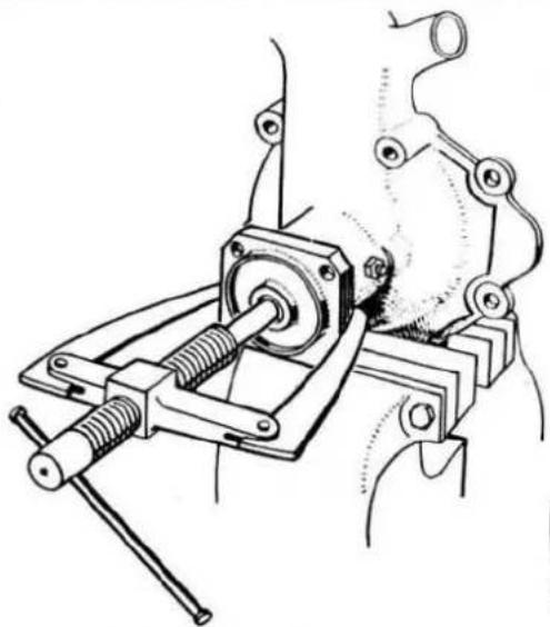
natural_image
Technical line drawing of a mechanical clamp or clamping device (no text or symbols present)Fig.2.9. Withdrawing the fan hub from the spindle

natural_image
Technical line drawing of a mechanical press or clamping device with no visible text or symbols
FIG.2.8. EXPLODED VIEW OF THE WATER PUMP
1 Pump body
2 Spindle and bearing assembly
3 Allen headed screw
4 Locknut
5 Thrower
6 Seal
7 Impeller
8 Pulley carrier
9 Gasket
10 Fan pulley
11 Setscrew
12 Shakeproof washer
13 Fan
14 Balance piece
15 Fan belt
16 By-pass water hose
17 Clip
18 Adaptor for heater return pipe (2.4 litre shown)
19 Copper washer

natural_image
Technical line drawing of a mechanical assembly with no visible text or symbolsFig.2.11. Fitting the impeller
13 Temperature gauge and thermal transmitter - general
The indicator head is attached to the instrument panel and in the case of Mk 1 models is connected by a capillary tube to a bulb located in the inlet manifold water jacket. The gauge, capillary tube and bulb are one unit and great care must be taken to ensure that the tube is not "kinked" or damaged in any way otherwise the whole unit will have to be replaced.
The indicator head of Mk 2, 240 and 340 models operates on a thermal principle using a bi-metal strip surrounded by a heater winding.
The transmitter unit is mounted in the inlet manifold water jacket adjacent to the thermostat.
14 Water temperature gauge Mk 1 models - testing, removing and refitting
from the dash casing. The casing can now be drawn outwards.
7 Remove both thumb screws from the top of the facia panel.
8 Remove the ignition keys and the cigar lighter.
9 Disconnect the battery.
10 Insert a piece of stiff wire into the hole in the side of the light switch to depress the plunger and the switch can now be withdrawn.
11 Repeat operation 10 to remove the wiper switch.
12 Remove the ashtray and remove both screws attaching the ashtray mounting bracket to the facia.
13 Remove the two large screws from the underside of the facia panel and the facia panel can now be removed by sliding it over the remaining switches.
14 Mark the relative positions of the three instrument panel securing bolts and remove them.
15 Ease the instrument panel forward into the car and unscrew the oil gauge union nut from the rear of the instrument.
16 Remove the two screws securing the temperature gauge to the instrument panel and withdraw the gauge into the car complete with the capillary tube and bulb.
17 Refitting is the reverse of the above procedure but taking care to see that the tube follows its original track and that it is not kinked when placing it on its clips.
18 Top up the cooling system with soft water.
15 Water temperature gauge thermal transmitter Mk 2, 240 and 340 models - testing, removing and refitting
1 If unsatisfactory gauge readings are being obtained, the thermal transmitter can be tested by removing the cable connection on the transmitter and placing the metal cable end on a good earthing point. Switch on the ignition and note the movement of the needle of the gauge, if it moves to a hot sector a new thermal transmitter should be fitted. If the needle fails to move then a break in the wiring or a fault in the gauge (which can be tested by substitution) will be the cause of the trouble.
2 To remove the thermal transmitter, partially' drain the cooling system.
3 Disconnect the battery.
4 Unscrew the transmitter gland nut from the inlet manifold water jacket and remove the transmitter.
5 Refitting is the reverse procedure to removal.
6 For information on removal of the temperature gauge refer to Chapter 10.
16 Anti-freeze - mixture
During the winter months an anti-freeze compound with an inhibited Ethylene Glycol base should be used in the proportions laid down by the manufacturers of the anti-freeze mixture. It should be remembered, if an anti-freeze mixture is not used, that it is possible for the radiator to "freeze-up" whilst the car is being driven even through the water in the radiator was not frozen before the car was started.
Before adding anti-freeze solution, check all water unions and the tightness of the cylinder head bolts. Flush out the system as described in Section 3 and allow the system to drain. Close all drain taps. To ensure satisfactory mixing of the water and anti-freeze solution, measure the recommended proportions into a container and fill the system from this container rather than add the solution direct to the system. If "topping up" is necessary during the period that anti-freeze is in use, remember that the addition of straight water will dilute the mixture and so the required degree of protection against frost damage will be lost.
17 Fault diagnosis
| Symptom | Reason/s | Remedy |
| Overheating | Insufficient water in cooling systemFan belt slipping | Top up radiatorTighten fan belt to recommended tension or replace if worn. |
| Radiator core blocked or radiator grille obstructedThermostat not opening properlyIgnition advance and retard incorrectly set (accompanied by loss of power and perhaps misfiring)Incorrect fuel/air mixtureExhaust system partially blockedOil level in sump too lowBlown cylinder head gasket (water/steam being forced down the radiator overflow pipe under pressure)Engine not yet 'run-in'Brakes binding | Reverse flush the radiator, remove obstruction from grilleRemove and fit new thermostat.Check and reset ignition timing.Tune carburettors.Check exhaust pipe for obstruction.Top up to correct level.Remove cylinder head and fit new gasket.Run-in slowly and carefully.Check and adjust brakes. | |
| Engine running 'cold' | Thermostat jammed openIncorrect grade of thermostat fittedThermostat missing | Remove and renew thermostat.Remove and replace with correct type of thermostat.Check and fit correct thermostat. |
| Leaks in system | Loose clips on water hoses.Top or bottom water hoses perishedRadiator leakingThermostat gasket leakingPressure cap spring worn or seal ineffective Cylinder wall or head crackedCore plug corroded | Check and tighten clips.Check and replace any faulty hoses.Remove radiator and repair.Inspect and renew gasket.Renew pressure capDismantle engine and despatch to engineering works for repair.Remove old plug and fit new item. |
Chapter 3 Fuel system and carburation
Contents
| General description | ... | ... | ... | ... | ... | 1 |
| Fuel pump - general description | ... | ... | ... | 2 | ||
| Fuel pump - removal and replacement | ... | ... | 3 | |||
| Fuel pump - dismantling | ... | ... | ... | 4 | ||
| Fuel pump - examination | ... | ... | ... | 5 | ||
| Fuel pump - reassembly | ... | ... | ... | 6 | ||
| Fuel pump - fault finding | ... | ... | ... | 7 | ||
| Petrol tank - removal and refitting | ... | ... | ... | 8 | ||
| Petrol gauge, tank unit - removal and refitting | ... | 9 | ||||
| Carburettor Solex B32 PB-5 - description | ... | ... | 10 | |||
| Carburettor (Solex) - removal and replacement | ... | ... | 11 | |||
| Carburettor (Solex) - dismantling and reassembly | ... | ... | 12 | |||
| Carburettor (Solex) - cleaning and inspection | ... | ... | 13 | |||
| Carburettor (Solex) - adjustment and synchronisation | ... | 14 | ||||
| Carburettor (Solex) - sudden break in performance | ... | 15 | ||||
| Carburettor (Solex) - poor slow running | ... | ... | 16 | |||
| Carburettor (Solex) - heavy fuel consumption | ... | 17 | ||||
| Carburettor (Solex) - failure to respond to throttle opening | 18 | |||||
| Carburettor (Solex) - flat spot (engine hot) | ... | ... | 19 | |||
| Carburettor (Solex) - difficult starting when engine cold | 20 | |||||
| Carburettor (Solex) - deterioration of performance | ... | 21 |
| Carburettor SU type HD6 and HS6 - general description | ... | 22 |
| Carburettor SU - removal and replacement ... | ... | 23 |
| Carburettor HD6 - dismantling and reassembly | ... | 24 |
| Carburettor HS6 - dismantling and reassembly | ... | 25 |
| Carburettor SU - examination and repair ... | ... | 26 |
| Carburettor SU - piston sticking ... | ... | 27 |
| Carburettor SU - float needle sticking | ... | 28 |
| Carburettor SU - float chamber flooding | ... | 29 |
| Carburettor SU - water or dirt in carburettor | ... | 30 |
| Carburettor HD6 - jet centering ... | ... | 31 |
| Carburettor HS6 - jet centering ... | ... | 32 |
| Carburettor SU - needle replacement ... | ... | 33 |
| Carburettor SU - adjustment and tuning - general | ... | 34 |
| Carburettor HD6 - adjustment and tuning ... | ... | 35 |
| Carburettor HS6 - adjustment and tuning ... | ... | 36 |
| The auxiliary starting carburettor - description | ... | 37 |
| The auxiliary starting carburettor - adjustment | ... | 38 |
| The thermostatic switch - removal and refitting | ... | 39 |
| Fault diagnosis ... ... ... ... ... ... | ... | 40 |
Specifications
| Air cleaner | |||||||
| Type ... | ... | ... | ... | ... | ... | ... | 2.4 litre Mk's 1 and 2 - oil bath (early models - wiremesh)3.4/3.8 litre - wire mesh and oil bath (early models)paper element (later models)240/340 - paper element |
| Carburettor | |||||||
| Type ... | ... | ... | ... | ... | ... | ... | 2.4 litre Mk's 1 and 2 - twin Solex B32 PBI-5240 - twin SU HS6 1 12 "3.4/3.8/340 - twin SU HD6 1 12 " |
| Solex B32 PBI-5 | Compression ratio | ||||||
| Choke and jet sizes | ... | ... | ... | ... | ... | ... | 7 to 18 to 1 |
| Choke | ... | ... | ... | ... | ... | ... | 23 mm24 mm |
| Main jet | ... | ... | ... | ... | ... | ... | 110110 |
| Air correction jet | ... | ... | ... | ... | ... | ... | 200180 |
| Emulsion tube | ... | ... | ... | ... | ... | ... | 1414 |
| Pump jet | ... | ... | ... | ... | ... | ... | 5555 |
| Pilot jet | ... | ... | ... | ... | ... | ... | 5050 |
| Pilot air bleed | ... | ... | ... | ... | ... | ... | 1.2 mm1.2 mm |
| Needle valve | ... | ... | ... | ... | ... | ... | 1.5 mm1.5 mm |
| Needle valve washer | ... | ... | ... | ... | ... | 1 mm1 mm | |
| Starter petrol jet | ... | ... | ... | ... | ... | ... | GS.105GS.105 |
| Starter air jet | ... | ... | ... | ... | ... | ... | GA.4.5GA.4.5 |
Compression ratio
SU HD6 Needles
| 3.4 litre | 7 to 1 comp ratio | ... | ... | ... | ... |
| 8 to 1 comp ratio | ... | ... | ... | ... | |
| 9 to 1 comp ratio | ... | ... | ... | ... | |
| 3.8 litre | 7 to 1 comp ratio | ... | ... | ... | ... |
| 8 to 1 comp ratio | ... | ... | ... | ... | |
| 9 to 1 comp ratio | ... | ... | ... | ... | |
| 340 | 8 to 1 and 9 to 1 comp ratio | ... | ... | ||
| Jet size | ... | ... | ... | ... | ... | ... | ... |
| Auxiliary starting carburettor - needle type | ... | ... | ... | ... | |||
SU HS6 Needles
| Oil bath | Paper element |
| SC | TM |
| SC | CI* |
| SC | CI* |
| TX | TM |
| SC | CI* |
| SC | CI* |
| CI or TL | |
| * Early cars fitted with TU needles | |
| 0.10 in (2.54 mm) | |
| 425/8 |
TL
| 0.10 in (2.54 mm) | |
| SU electrical | Early models HP type AUA.52 |
| AUA.152 | |
| AUB.152 | |
| Later models | AUF.301 |
| AUF.303 | |
Flat tank under rear floor vented through filler cap 12 Imp gallons (54½ litres)
1 General description
A lay-out of the fuel system is shown in Fig.3.1. It consists of a fuel tank at the rear of the car, an electrical fuel pump located in the luggage compartment and twin curburettors, Solex in the case of the 2.4 litre range and SU for all other models. The 2.4 litre Mk's 1 and 2 cars are fitted with an oil bath type of air
cleaner but early models had a wire mesh type. Early model 3.4 and 3.8 litre cars were fitted with wire mesh or oil bath air cleaners but later models, and the 240 and 340, have a disposable paper element type. Irrespective of the type of air cleaner in use it should be serviced at the recommended periods. Operation of the individual components is described elsewhere in this Chapter.

2 Fuel pump - general description
A sectioned view of the type of fuel pump fitted to early model cars is given in Fig.3.2. The pump consists of three main assemblies - the body, the magnet assembly (sometimes referred to as the coil housing assembly) and the contact breaker.
The body (A) is an aluminium casting to which is attached two identical lids ("B" the top and "C" the lower). The lower lid retains the filter and the top lid gives access to the cage "D" for the outlet valve "E", and, when the cage is unscrewed, to the inlet valve "F" also. These inlet and outlet valves are thin brass discs and should be assembled smooth side downwards. It is rarely necessary to remove the outlet valve but it can be extracted after the spring circlip has been detached, care should be taken not to distort this circlip or the valve lift may be affected.
There is a space between the valves and the pumping chamber which is a shallow depression one face of the body casting. This space contains the diaphragm unit "J" which is clamped on its rim between the iron coil housing "K" and the main body "A".
A bronze rod "L" is screwed to the centre of the armature "M", to which the diaphragm is also fastened and it passes through the magnet core "N" to the trunnion "O" in the contact breaker. An armature return spring "P" is interposed between the armature and the end of the magnet coil.
The magnet consists of a cast iron housing "K" having an iron magnet core "N" on which is wound a coil of copper wire "Q" which energises the magnet. Between the magnet coil housing "K" and the armature "M" are fitted eleven spherical edged rollers "R", these locate the armature centrally within the magnet and allow absolute freedom of movement in a longitudinal direction. The contact breaker is a small bakelite moulding "S" carrying two rockers, an inner rocker "T" and an outer rocker "U", these are both hinged to the moulding at one end are connected together at their top end by two small springs arranged to give a "throw over" action. A trunnion bearing "O" is fitted into the centre of the inner rocker and the bronze armature sliding rod "L" is screwed into it. The outer rocker is fitted with tungsten points and these make contact with the corresponding points on the spring blade "V", this blade is connected to one end of the coil and the other end of the coil is connected to the terminal screw "W". The outer rocker is connected by a short length of flexible wire to one of the screws which holds the bakelite moulding and thus provides an earth. Arcing at the contact breaker is reduced by a condenser which is fitted in parallel with the points.
The pump operates as follows; when at rest the outer rocker lies in the outer position and the tungsten points are in contact. When the ignition is switched on, current passes from the terminal, through the coil, back to the blade, through the points and to earth, thus energising the magnet and attracting the armature. The armature moves forward and brings the diaphragm with it thus creating a vacuum and sucking the petrol through the suction valve into the pumping chamber. When the armature has advanced nearly to the end of its stroke, the "throw over" mechanism operates and the outer rocker flies back and so separates the points and breaks the circuit. The spring "P" then pushes the armature and the diaphragm back, forcing petrol through the delivery valve at a rate determined by the requirements of the engine. As soon as the armature gets near the end of this stroke, the "throw over" mechanism again operates, the points again make contact and the cycle of operations is repeated.
The spring blade rests against a small projection on the bakelite moulding, and it should be set so that when the points are in contact it is deflected back from the moulding. The width of gap at the points is approximately 0.030" (0.75 mm), when the rocker is pulled back against the face of the iron housing. If the magnet is removed from the body for any reason, care must be taken that the rollers "R" do not fall out.
The above description also applies to a short body version of

pump which was introduced for later Mk 2 models. The coil housing of this pump is approximately 2¼" in length compared to 2¾" of the earlier type. However, the above pumps were superseded by the AUF.301 (late model Mk 2 and 3.8 litre cars) and by the AUF.303 as fitted to 240 and 340 models but which may also be found on the other range of cars. These pumps differ considerably from the pump described above as will be seen from the sectioned drawing (of the AUF.301) which is shown at Fig.3.3. This pump also comprises three main assemblies: the main body casting "A", the diaphragm armature and magnet assembly "M" contained within the housing, and the contact braker assembly housed within the end cap "T2". A non-return valve assembly "C" is fixed to the end cover moulding to aid the circulation of air through the contact breaker chamber. The main fuel inlet "B" is maintained in communication with an inlet air bottle "I".
Communication with the main pumping chamber "N" is provided by an inlet valve assembly, this assembly comprises a Melinex valve disc "F" permanently assembled within a pressed steel cage, which, in turn is held in place by a valve cover "EI", while the outlet from the pumping chamber is provided with an identical valve assembly reversed in direction. Inlet and outlet valve assemblies and filters are held in position by a clamp plate "H", both valve assemblies may be removed by detachment of the clamp plate after removing the self tapping screws shown on the lower diagram in Fig.3.3. A filter "E" is provided upstream of the inlet valve assembly. The delivery chamber "O" is bounded by a flexible plastic spring loaded diaphragm "L" contained by the vented cover "P". The rubber sealing ring "L2" seals the diaphragm "L".
The magnetic unit consists of an iron coil housing an iron core "Q", an iron armature "AI" which is provided with a central spindle "PI" and is permanently united with the diaphragm assembly "LI", a magnet coil "R" and a contact breaker assembly comprising parts "P2", "UI", "U", "TI", "V" etc. Between the coil housing and the armature are located 11 spherically edged rollers "S" which locate the armature "AI" centrally within the coil housing and so allow absolute freedom of movement in a longitudinal direction.
The contact breaker consists of a bakelite pedestal moulding "T" carrying two rockers "U" and "UI" which are both hinged to the moulding at one end by the rocker spindle "Z" and interconnected at their top ends by two small springs arranged to give a "throw-over" action. A trunnion "P2" is carried by the inner rocker and the armature spindle "PI" is screwed into the trunnion. The outer rocker "U" is fitted with two tungsten points which contact with two tungsten points carried by the spring blade "V" which is connected to one end of the coil whilst the other end of the coil is connected by a short length of wire, "X", to one of the screws which hold the pedestal moulding onto the coil housing and this provides an earth return to the body of the pump which must, in turn, be thoroughly earthed to the body of the vehicle by the earthing terminal provided on the flange of the coil housing.
The action of the pump is that when it is at rest the outer rocker "U" lies in the position illustrated with the tungsten points in contact. When the ignition is switched on, current passes from the connector "W" through the coil and back to the blade "V", through the points and so to earth, thus energising the coil and attracting the armature "AI". The armature, together with the diaphragm assembly then retracts and so creates a vacuum to suck fuel from the tank into the pumping chamber "N" through the inlet valve. When the armature is close to the end of its stroke, the throw-over mechanism operates and the outer rocker moves rapidly backwards, thus separating the points and breaking the circuit. The spring "SI" then pushes the armature and diaphragm away from the coil housing and so forces fuel through the delivery valve at a rate according to engine requirements. As the armature approaches the end of its stroke the throw-over mechanism again operates, the tungsten points again make contact and the cycle of operations is repeated. The spring blade "V" rests against the small projection moulding "T" and it should be set so that when the points are in contact it is deflected away from the moulding. The extent of the gap at the points should be approximately 0.030" (0.75 mm) when the rocker "U" is manually deflected until it contacts the end face of the coil housing.

Fig.3.3. The AUF fuel pump (AUF 301 illustrated)
3 Fuel pump - removal and replacement
1 Disconnect the battery.
2 Disconnect both inlet and outlet fuel pipes, from the side of the pump by withdrawing the banjo bolts and washers.
3 Disconnect the electrical feed to the pump by unscrewing the knurled knob at the end of the pump.
4 Disconnect the earth cable from the side of the pump.
5 Remove the two self locking nuts attaching the pump to its bracket and withdraw the washers from each stud.
6 The pump may now be withdrawn from the bracket leaving the two rubber grommets in position.
7 Refitting is the reverse of the above procedure but the two rubber grommets should be examined for deterioration and replaced if necessary, otherwise excessive pump noise may result.
4 Fuel pump - dismantling
The general procedure for dismantling the three types of pump (HP type long and short body and the AUF type of pump) is very similar but, where differences occur, separate details are given.
1 Ensure that the outside of the pump, the bench and your hands, are clean.
2 Refer to Figs. 3.2 and 3.3.
3 Remove the nut and washer from the terminal screw "W" and the cover sleeve seal (if fitted).
4 Remove the end cover and the spring blade "V".
5 Mark the relative position of the coil housing and the body. Remove the six set screws which secure the coil housing and body and separate them. The edges of the diaphragm are now free and the spherical rollers, "R" in Fig.3.2 and "S" in Fig.3.3 should be removed.
6 Unscrew the diaphragm unit (J or LI) anti-clockwise, note that the rod and diaphragm are not separable.
7 Remove the nut from the terminal screw and the lead washer beneath it. Remove the two pedestal screws and release the pedestal.
8 Disconnect the electrical leads after noting their position for reassembly.
9 Push out the rocker spindle pin ("Z" in Fig.3.3) to release the rocker assembly which cannot be dismantled any further. DO NOT remove the toggle springs.
10 On the HP type pump, remove the six screws retaining the top lid, unscrew the valve cage "D" and remove the inlet valve "F". The brass outlet valve "E" is removed from the cage after removing the circlip.
11 Remove the lower lid "C" to gain access to the filter.
12 On the AUF type pump both the valve assemblies can be removed by unscrewing the two self tapping screws securing the plate "H". The valves are of Melinex plastic as opposed to brass in the HP type pump. Note that the filter "E" is incorporated with the inlet valve.
13 It is unnecessary for the cover "P", the spring loaded diaphragm "L", the perforated disc and rubber sealing ring "L2" to be dismantled.
5 Fuel pump - examination
1 Examine the contact points for burning or pitting. If the points are defective, the rocker assembly and spring blade should be renewed.
2 Check that all electrical leads and tags are in good condition.
3 Examine the diaphragm for deterioration. Renew it if its condition is at all doubtful.
4 Clean the filter and examine it for damage looking especially for cracks.
5 Check the condition of the valves on HP pumps and renew them if doubtful of their condition.
6 Examine the Melinex valves of the AUF type pump and
check that they seat properly. Note that the retaining tongue on the cage should allow the valve to lift approximately 1/16".
7 Examine the valve seatings and if they are pitted the body will have to be replaced.
8 Check that the non-return valve "C", which aids the circulation of air through the contact breaker chamber, is free.
6 Fuel pump - reassembly
1 Fit the rocker assembly to the pedestal with the rocker spindle pin. Ensure that the rockers are free in action, this may require slight lubrication of the pivots.
2 Fit the terminal screw "W" to the pedestal and then fit the double coil spring washer, the cable tag, the new lead washer and the nut in that order. Tighten the nut. (see Fig.3.4 for assembly detail).
3 Fit the two pedestal screws and the earthing lead tag and re-attach the pedestal, hold the tag against turning with the screw and do not overtighten or the pedestal may be fractured.
4 Fit the impact washer over the diaphragm rod to enter the recess in the armature, "M" in Fig.3.2 and "AI" in Fig.3.3. Fit the large diameter of the armature spring into the coil housing. Enter the thread of the diaphragm rod into the trunnion, "O" in Fig.3.2 and "P2" in Fig.3.3. Turn the diaphragm clockwise until the rocker will just not throw over.
5 Hold the coil housing vertical with the diaphragm uppermost, turn back the edge of the diaphragm and fit the eleven spherical edged rollers.
6 Hold the unit horizontally as shown in Fig.3.5. Unscrew the diaphragm one sixth of a turn at a time (one hole), press the diaphragm in and release slowly and firmly (not jerkily) until the "throw-over" mechanism operates. Unscrew a further turn (five to six holes) for the long body HP pump, and unscrew a further 1 14 turns (seven holes) for the short body HP and for the AUF pumps.
7 The body may now be fitted to the coil housing.
8 The following paragraphs apply to HP pumps - assemble the body to the housing in its original position. Engage the six set screws finger tight at this stage. Fit the spring contact blade and adjust and tighten it so that each contact point wipes over the centre line of the other point and not to one side of either contact. The diaphragm must now be stretched to its outermost position and this is most easily done by inserting a matchstick behind one of the white fibre rollers on the outer rocker, thus holding the points in contact. If a current is now passed through the pump, the magnet will be energised and will pull the armature and diaphragm forward and whilst it is in this position the six setscrews should be tightened down. Alternatively the diaphragm can be stretched by using a diaphragm stretching tool as illustrated in Fig.3.6. This is a steel wedge which is inserted under the trunnion "O" in the centre of the inner rocker in order to stretch the diaphragm to its outermost position. Fig.3.7 illustrates the tool in position.
9 Check the gap between the white rollers and the coil housing, as shown in Fig.3.8, by holding the spring blade against the projection "B". The tip of the blade should be "set" to obtain the correct clearance.
10 Refit the inlet valve, the outlet valve cage, the outlet valve, the retaining circlip and the top lid.
11 Refit the filter and the bottom lid.
12 The following paragraphs apply to AUF type pumps - Fit the valves and their retaining plate. Make sure that each is the right way round for inlet and outlet and that the filter is fitted below the inlet valve.
13 Attach the body in its original position to the coil housing and fully tighten the six securing setscrews.
14 Check that the top of the inner rocker "UI" has made contact with the end face of the coil housing as indicated at "XI". If there is a visible, or measurable, gap then the six screws should be slackened off and retightened until the condition of contact at "XI" is obtained.
15 Fit the soring blade and position it so that when the outer
rocker operates to make and break contact between the tungsten points the one pair of points wipes over the centre line of the other pair in a symmetrical manner.
16 Set the spring blade to give a gap of 0.030" (0.75 mm) between the points when the rocker "U" is manually deflected and touches the end face of the coil housing.
17 Fit the cover and sealing sleeve.

FIG.3.4. THE TERMINAL ARRANGEMENT
A Double coil spring washer C Lead washer B Cable tag D Countersunk nut

natural_image
Illustration of hands using a mechanical device to measure a cylindrical component (no text or symbols visible)Fig.3.5. Checking 'throw-over' of the toggle mechanism
7 Fuel pump - fault finding
1 If fuel is not reaching the carburettors, first check that the fuel tank venting is not blocked.
2 Disconnect the delivery pipe to the carburettor and switch on the ignition. If the pump works, the trouble is probably due to a sticking needle in the float chamber.
3 If the pump does not work, disconnect the lead from the terminal and strike against the body of the pump to see if it sparks and, therefore, if any current is available. If there is current there, remove the cover of the pump and touch the terminal with the lead when the points are in contact. If the pump fails to work it may be due to dirt on the contact faces. This may be cleaned off by inserting a thin piece of card between the contacts and working it to and fro.
4 If the pump still fails to work after cleaning the contacts, check that the bottom filter is not blocked.
5 If the filter is clear, slacken off the inlet pipe union and if the pump operates when the ignition is switched on the trouble is probably due to an obstruction in the pipe line to the tank. It may be possible to clear the obstruction by blowing down the pipe with a foot pump.
6 If the pump does not operate after slackening the inlet union, slacken the outlet union. Switch on and if the pump operates the fault will be due to an obstruction in the pipe line between the pump and the carburettors. Check that the glass petrol filter unit
in the engine compartment is clear. If it is clear, the fault will lie in the pipe line itself and a blow down with a foot pump will probably clear the trouble.
Note: Under no circumstances must compressed air be applied to the pump as this will damage the valves.
7 If, when either union is slackened off, the pump does not operate or only works slowly or spasmodically, then the trouble is due to a fault in the pump itself, such as a stiffened up diaphragm or undue friction in the throw-over mechanism or a combination of both.
8 To check the above, unscrew the six screws and detach the coil housing and rocker unit from the main body. Take care not to lose any of the rollers under the diaphragm.
9 Press on the diaphragm gently and firmly and observe whether the throw-over mechanism seems to operate freely. If it does not, lubricate sparingly, with a drop of thin oil, where the steel spindles pass through the brass rockers.
10 Now, to restore the original pliability of the diaphragm, ruckle each of the two fabric layers vigourously between the thumb and fingers. Reassemble and carefully set the throw-over as described in Section 6 paragraph 6.
11 If the pump becomes noisy in operation, look for an air leak on the suction side. The simplest way to check for this is to disconnect one of the carburretor feed pipes and allow the pump to discharge petrol into a glass jar until the pipe is immersed in petrol. If bubbles are seen to come through the pipe there must be an air leak which must be traced and cured.
12 If the pump keeps operating but does not deliver any fuel, the fault is probably due to a piece of dirt trapped under one of the valves which will mean dismantling and cleaning the pump as already described.
13 If the pump overheats in operation, the fault will probably be due to an obstruction on the suction side.
8 Petrol tank - removal and refitting
It is not essential to drain the tank before removal as it can be lowered vertically from its mounting.
1 Raise the rear of the car to allow work to be carried out underneath.
2 Remove the three (two on the 2.4 litre) exhaust silencer mountings. Remove the bolts securing the exhaust tail pipe to the rear body coupling, the exhaust pipe(s) will now fall clear of the petrol tank.
3 Open the petrol filler door on the left hand rear wing and remove the filler cap.
4 Disconnect the flexible petrol pipe from the tank by unscrewing the union above the large grommet located on the trim panel on the left hand side of the luggage compartment.
5 Remove the cover of the petrol gauge tank unit on the left hand side of the luggage compartment floor and disconnect the three cables. Note their position for reassembly.
6 Remove the three self locking nuts attaching the tank to the body. Take the weight of the tank and remove the mounting rubbers and washers.
7 Lower the tank to the floor and remove the remaining distance pieces, rubber pads and washers from the tank mounting studs; note their position for reassembly.
8 Refitting is the reverse of the removal procedure but ensure that the rubber mounting washers are correctly positioned and have an assistant to ensure that the electrical cables are drawn up through the cover plate aperture as the tank is offered up to its mounting. To ensure that the cable connectors are correctly attached to the blade terminals, slide back the insulating sleeve and push the connector fully onto the blade. Push back the insulating sleeve to cover the joint.
9 Petrol gauge, tank unit - removal and refitting
2 Disconnect the electrical cables. Note their position for reassembly.
3 Remove the six setscrews (and earth wire) and the twelve copper washers which attach the unit to the petrol tank.
4 Break the seal by a sharp tap on one side of the unit. Withdraw the unit taking care not to damage the float arm.
5 To refit the unit, first remove the old gasket and any sealing compound from the boss on the petrol tank taking care that none falls into the tank.
6 Use a new gasket and apply a suitable sealing compound to both sides. Position the gasket on the petrol tank boss with the holes in line.
7 Insert the element into the tank so that the float is towards the front of the car.
8 Replace the six screws and twelve washers and tighten securely.
9 Slide back the insulating sleeve from the cables and push the connectors fully home on the blades from which they were removed (should be white/green cable to terminal marked "W" at the front of the unit and the green/black cable to the terminal marked "T" at the rear).
10 Remove one of the screws on top of the element housing and secure the black earth wire.
11 Replace the unit cover plate.

Fig.3.6. The diaphragm stretching tool

natural_image
Technical line drawing of a mechanical device with no visible text or symbolsFig.3.7. The diaphragm stretching tool in position

Fig.3.8. Checking the gap of the rollers
10 Carburettor Solex B.32 PB - 5 - description
The 2.4 litre model is equipped with twin Solex B.32 PB-5 carburetters. This type of carburetter is fully dust proofed (by the air cleaner) and has a progressive starting device with fast idle; it also incorporates an anti-percolation device and accelerator pump. For idling, the mixture is supplied to the engine past the butterfly and from the pilot jet and the pilot jet air bleed.
Engine speed can be varied by a slow running adjustment screw which opens or closes the throttle as required whilst adjustment of the volume control screw varies the mixture strength and volume from the pilot jet and the pilot air bleed. For normal running, petrol is supplied from the float chamber through the main jet to the main well where it is mixed with air metered through the air correction jet and carried into the well via the emulsion tube. The mixture is then discharged from the main spraying well into the air stream passing through the choke tube. An accelerating and economy pump is attached to the float chamber and is operated by inter-connected throttle linkage. The main components of this unit are a membrane and spindle, a return spring, an inlet valve and a spring controlled outlet valve. When the accelerator is released, the membrane is pushed back by the spring, thereby drawing in petrol via the inlet valve. When the accelerator is depressed, the membrane is pushed forward and this causes the petrol in the pump to close the inlet valve and, calibrated through the pump jet, it is then discharged into the main air stream via the injector tube. The pump has the additional function of supplementing the output of the main jet for full power, for, when the throttle is fully held open the pump lever holds the membrane forward, which in turn keeps the inlet valve open, thus creating an open circuit through which petrol is drawn by engine depression via the injector tube. Easing the accelerator to return to normal cruising closes the outlet valve and stops the supplementary supply.
11 Carburetters Solex - removal and replacement
1 Bend the rubber seal, which joins the air intake pipe to the air cleaner, back on to the air cleaner flange.
2 Disconnect the air intake steady bracket and the air intake pipe can now be removed by applying steady pressure under the centre. Do not lose the two connecting sleeves from the top of the carburettors.
3 Remove the three bolts securing the air cleaner to the mounting bracket and remove the air cleaner (if desired).
4 Disconnect the distributor vacuum feed pipe from the front carburettor by unscrewing the union.
5 Disconnect the accelerator linkage from the throttle spindle.
6 Remove the two retaining setscrews from the mixture control levers. Remove the outer cable retaining setscrew. The control cable can now be withdrawn from the carburettors.
7 Disconnect the fuel feed pipes by undoing the banjo bolts. Note the washers and gauze filters, place these where they will not be lost.
8 Remove the two carburettor flange securing nuts, collect the spring washers.
9 Lift off the carburettors. Note the position of the two insulating distance pieces and the gasket, remove and discard them.
10 Refitting is the reverse of the removal procedure but fit two new insulating distance pieces and a new gasket to ensure against air leaks.
11 To refit the mixture control, ensure that the mixture level in the car is set at "RUN" and that the control levers on the carburettors are in the fully forward position. Thread the control wire into position and remember to replace the distance tube between the two choke levers (see Fig.3.10).
12 Carburettor (Solex) - dismantling and reassembly
1 Refer to Fig.3.11. The carburettors can be dismantled to the extent necessary for routine cleaning of jets and the float chamber without removing them from the engine. Proceed as follows.
2 Remove the air cleaner and the air intake pipe as described in Section 11.
3 Disconnect the fuel feed pipes to the carburettors by unscrewing the banjo bolts (Bb Fig.3.11) collect the washers and filter gauzes.
4 Unscrew the float chamber cover fixing screws and carefully remove each cover ("Fc").
5 The needle valves ("Nv") are now exposed and can be removed.
6 Lift and remove the float toggles (Ft), the spindles (Fs) and the floats (F).
7 Remove the pilot jet (g), the pump jet (Gp) and the starter jet which is situated at the bottom left hand side of the starter box and illustrated as item 20 in Fig.3.9.
8 Remove the pump non-return valve and gauze located at the base of the pump chamber (item 9 in Fig.3.9).
9 Remove the plug (Gu) and the main jet located in the bolt (T).
10 Remove the air correction jets (a) but before doing so ensure that the throttles are closed in case you accidentally drop any parts.
11 The emulsion tubes may now be lifted out using a matchstick.
12 It is rarely necessary that further dismantling of the carburettor is required but if it is desired to completely break down the item into component parts (but see Section 13 paragraph 7) for thorough cleaning after a long period of neglect it will have to be removed from the car and, after completing the operations at paragraphs 4 - 11 above, refer to Fig.3.9 and remove the remaining items in any sequence but take careful note of the position of parts as incorrect assembly will result in complete failure of the carburettor.
13 Before reassembling, check all carburettor assembly screws and flange nuts for tightness but do not use undue force.
14 Always use a new gaskets and fibre washers on reassembly as failure to do so may result in leaks and will upset the calibration of the carburettor.
15 Reassembly of the carburettor is generally the opposite to the sequence used in dismantling.
16 Note that the nose of the pilot jet seats on the casting but it should not be screwed in with such force as may damage the seating.
17 Use only the correct washers when refitting the needle valves to the float chamber covers as the thickness of the washers partly determines the petrol level. Make a final check on the needle stem for free movement.
13 Carburettor (Solex) - cleaning and inspection
1 Absolute cleanliness during servicing is essential. Before stripping the carburettor, clean it outside to remove all trace of dirt, oil grease etc.
2 Do not use rag for drying or cleaning the inside of the carburettor or its component parts. A clean tray of petrol, a small stiff paint brush (no loose hairs) and compressed air for cleaning the parts is quite adequate.
3 Remove sediment in the float chamber by gentle brushing followed by swilling out with petrol.
4 The interior of the carburettor and exposed passages should be blown out to ensure that all loose particles of foreign matter are removed.
5 Use only compressed air for cleaning jets. Never use wire as a probe as the orifice may be enlarged and this will result in an increase in petrol consumption and a possible reduction in engine performance.
6 Inspect floats for leakage and dents. Leakage can be detected by immersing the float in warm water and watching for air bubbles escaping. Leaking or dented floats should be replaced. Never repair a float except in dire emergency as the volume and weight of the float is important.
7 Thoroughly clean the needle valves with petrol and blow out. Check for freedom of movement.
8 The accelerating pump is especially set at the factory, therefore the unit should not be needlessly dismantled. However, should the membrane require replacing it should be noted that this item is not usually supplied separately but forms part of an assembly.
14 Carburettors (Solex) - adjustment and synchronisation
1 Correct adjustment and synchronisation of the carburettors is possible only if cylinder compressions, valve clearances, ignition setting, spark plug gaps and the contact breaker gap are within the limits given in the appropriate Chapters of this Manual.
2 Having ensured that the criteria of paragraph 1 are met, run the engine until it attains its normal running temperature.
3 Each carburettor has two external adjustments, the slow running adjustment screw (Z) Fig.3.11 and the mixture volume control screw (W).
4 Switch off the engine when running temperature is obtained and loosen the clamping bolt (B) Fig.3.11 on the flexible link between the carburettors. Ensure that the mixture control lever in the car is at "RUN", disconnect the mixture control levers at the carburettors and make sure that they are fully forward. Now starting with the front adjust each carburettor separately.
5 Unscrew the screw (Z) and ensure that the throttle is closed by pressing on the slow running screw. Place a piece of thin paper (or a 0.002" feeler gauge) between the screw and the casting stop and screw down until the paper is lightly nipped. Remove the paper and screw in on (Z) one further complete turn from that point.
6 Gently screw the volume control screw (W) clockwise until light contact is made with the casting seat, then unscrew three quarters of a turn.
7 Repeat the above adjustments To the rear carburettor.
8 Start the engine and have an assistant to watch the revolution counter. Adjust each slow running screw (Z) equally until the engine is running at 650 rpm. Now screw out each volume control screw (W) a quarter of a turn at a time working alternately between carburettors until a drop in rpm is registered.
9 Carefully and alternately, screw in each volume control screw by quarter turns until the engine reaches its highest and steadiest idling speed. Take care not to go beyond this point where erratic running will be evident due to weakness of the mixture.
10 If the engine speed is now other than 650 rpm adjust the slow running adjustment screws (Z) alternately each a part turn at a time to obtain the required idling speed and to maintain synchronisation.


FIG.3.9. EXPLODED VIEW OF THE SOLEX CARBURETTOR
1 Throttle chamber
2 Nylon insulating washer
3 Gasket
4 Control rod
5 Spring
6 Washer
7 Split pin
8 Float chamber
9 Non-return valve
10 Washer
11 Filter
12 Bolt
13 Main jet
14 Washer
15 Pump jet
16 Washer
17 Pilot jet
18 Air bleed
19 Starter air jet
20 Starter petrol jet
21 Washer
22 Choke tube
23 Screw
24 Emulsion tube
25 Air correction jet
26 Accelerator pump injector
27 Gasket
28 Float
29 Float spindle
30 Accelerator pump
31 Gasket
32 Starter valve
33 Starter valve body (front
carburettor)
34 Starter valve body (rear
carburettor)
35 Starter valve lever
36 Bolt
37 Float chamber cover
38 Needle valve
39 Washer
40 Gasket
41 Banjo bolt
42 Washer · small
43 Washer - large
44 Filter
45 Insulating washer
46 Gasket
47 Diaphragm
11 The throttle connecting linkage between the carburettors should now be tightened care being taken during this work to ensure that both throttles are against their stops.
12 Ensure that the mixture control lever in the car is at "RUN" and that the mixture control levers at the carburettors are fully forward. Reconnect the mixture control cable.
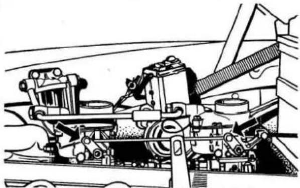
natural_image
Technical line drawing of a mechanical assembly with gears and levers (no text or symbols)Fig.3.10. Connection of mixture control wire
15 Carburettor (Solex) - sudden break in performance
This could be due to tiny particles of foreign matter or water passing the filters in the carburettors and the fuel pump, and blocking one or more of the petrol metering jets. The remedy is to clear the jets and clean the filters. If the petrol is badly contaminated with water, the petrol tank will have to be removed as described in Section 8 and swilled out into a clean container; the petrol can be reclaimed by straining through a chamois leather. Then clean out the petrol pipes and the glass filter bottle in the engine compartment, this filter will give an indication of the degree of contamination of the petrol.
16 Carburettors (Solex) - poor slow running
Sudden failure to idle smoothly may be due to one or both pilot jets becoming obstructed and failing to pass the quantity of petrol required by the engine. They should be removed and cleared by blowing through. When replacing the jets, screw them in securely but do not use undue force.
17 Carburettors (Solex) - heavy fuel consumption
If checks show that choke levers, ignition timing, carburettor tuning etc., are correct it is advised that the accelerator pump discharge injector tube (item 26 Fig.3.9) be checked for correct positioning. Check its position by placing a straight-edge across the lower face of the mounting block and measuring the gap between the end of the tube and the straight-edge as shown in Fig.3.12. The correct gap should be 0.020" to 0.040" (0.50 to 1.00 mm). If this dimension is not correct, a replacement assembly should be fitted as bending of the injector tube may loosen the tube in the mounting block. Ensure that the gasket is refitted under the base of the assembly and that the locating screw is tight.
18 Carburettors (Solex) - failure to respond to throttle opening
If the engine idles satisfactorily but suddenly fails to respond to throttle opening, the fault will probably lie in the main jets, these should be removed for cleaning. The main jets are assembled in holders the heads of which are clearly marked "Main Jet Holder" (refer to item "T" in Fig.3.11). Remove the jet holder and gripping the head between the jaws of a spanner the jet can be removed with a screwdriver and blown out. Removal of the jet holder will allow the float chamber to drain and this will assist in carrying away any impurities.

FIG.3.11. VIEW OF CARBURETTORS INSTALLED
WITH FLOAT CHAMBER COVERS REMOVED
Bb Banjo bolt
Fc Float chamber cover
Nv Needle valve
F Float
Fs Float spindle
Ft Float toggle
g Pilot jet
Gp Pump jet
Gu Plug
T Main jet holder
a Air correction jet
B Clamping bolt
Z Slow running adjustment
screw
W Volume control screw

Fig.3.12. Checking the position of the injector tube
19 Carburettors (Solex) - flat spot (engine hot)
Should hesitation be noted when accelerating from slow to normal speeds, the pump jets may be partly or completely blocked and should be removed for cleaning. After replacing the jets and priming the carburettors, the pump action should be checked in the following manner:- remove the air cleaner pipe and open the throttle. A discharge should now occur from each pump injector visible in the choke tubes of the carburettors.
20 Carburettors (Solex) - difficult starting when engine cold
Provided the petrol supply is satisfactory and the battery is in good condition and a good spark is being obtained, the engine should start immediately. If it does not and there is no smell of petrol after the starter has been operated two or three times, the starter jets may need blowing out to clear obstructions.
21 Carburettors (Solex) - deterioration of performance
Do not be too ready to blame the carburettors for poor performance but after a long period of use some wear, as may affect performance, must be expected. Therefore, when the time arrives for a major overhaul of the engine serious consideration should be given to replacing the carburettors with manufacturer's reconditioned items in order to take full advantage of other work being put into the engine.
Note:- when refitting main, petrol and starter jets make certain that each fibre sealing washer is undamaged and that the jets are securely tightened.
22 Carburettors SU type HD 6 and HS 6 - general description
1 The 3.4 and 3.8 litre and the 340 models are fitted with twin SU type HD 6 carburettors whilst the 240 model has twin SU HS 6 carburettors, these are illustrated in Figs.3.13 and 3.14. They are generally similar in appearance and operation the main difference in contraction being that in the case of the HD 6 the jet is fixed and the mixture is controlled by an external screw and lever (item B in Fig.3.28) whilst in the HS 6 type the position of the jet in relation to the needle can be adjusted by means of an adjusting nut at the base of the carburettor and this movement of the jet controls the mixture.
2 These variable choke carburettors differ from most other makes in that, instead of having a number of various sized fixed jets for different conditions, only one variable jet is fitted to deal with all possible conditions.
3 Air passing rapidly through the carburettor draws petrol from the jet so forming the petrol/air mixture. The amount of petrol drawn from the jet depends on the position of the tapered carburettor needle, which moves up and down the jet orifice according to the engine load and throttle opening, thus effectively altering the size of the jet so that exactly the right amount of petrol is metered for the prevailing conditions.
4 The position of the tapered needle in the jet is determined by engine vacuum. The shank of the needle is held at its top end in a piston which slides up and down the dashpot in response to the degree of manifold vacuum.
5 With the throttle fully open, the full effect of inlet manifold vacuum is felt by the piston which has an air bleed into the choke tube on the outside of the throttle. This causes the needle to rise fully bringing the needle with it. With the accelerator partly closed only slight inlet manifold vacuum is felt by the piston (although of course, on the engine side of the throttle the vacuum is greater), and the piston only rises a little, blocking most of the jet orifice with the metering needle.
6 To prevent the piston fluttering and giving a richer mixture when the accelerator pedal is suddenly depressed, an oil damper and a light spring are fitted inside the dashpot.
7 The only part of the piston assembly to come into contact with the piston chamber or dashpot is the actual piston rod. All other parts of the piston assembly, including the lower choke portion, have sufficient clearance to prevent metal to metal contact which is essential if the carburettor is to function correctly.
8 The correct level of the petrol in the carburettor is determined by the level of the float in the float chamber. When the level is correct, the float, by means of a lever resting on top of it, closes a needle valve in the cover of the float chamber and this cuts off the supply of fuel from the tank. As fuel is used in the carburettor, the float drops and in so doing the float needle is unseated and allows more fuel to enter the float chamber.
9 The HD 6 carburettors employ a separate starting carburettor. But with the HS 6 model the rich mixture for starting is obtained by manually pulling down the jet to a smaller diameter of the needle.
23 Carburettor (SU) - removal and replacement
1 Disconnect the battery (for HD 6 carburettors) as a safety measure.
2 Undo the butterfly nut to the centre bolt of the air cleaner and lift out the air cleaner.
3 Undo the two bolts securing the air intake pipe to the carburettors and remove the pipe.
4 Disconnect the lead from the auxiliary starting carburettor to the thermostatic switch on the inlet manifold (HD 6 carburettors only).
5 Disconnect the auxiliary starting carburettor to manifold connection (HD 6 carburettors only).
6 Remove the split pin, plain and spring washers from the connecting link pivot located on the manifold between the front and rear carburettors and disconnect the throttle link rod joint from the ball pin on the bell crank lever.
7 Disconnect the choke cable and the throttle linkage from the pivot pin between the carburettors (HS 6 carburettors only).
8 If automatic transmission is fitted, remove the spring clip which secures the kick down rod to the front carburettor.
9 Disconnect the distributor vacuum pipe from the front carburettor.
10 Disconnect the accelerator return spring if fitted to the particular model.
11 Remove the clip which attaches the float chamber overflow pipes to the oil filter.
12 Remove the nuts and washers securing each carburettor to the inlet manifold.
13 Remove the carburettors together with the insulating distance pieces.
14 Refitting is the reverse of the removal procedure, but particular attention must be paid to the throttle linkage setting of the carburettors.
15 The following paragraphs 16 - 20 inclusive refer to the HD 6 carburettor.
16 With the front carburettor coupling and the rear carburettor throttle lever released, check that both butterflies are fully closed and that the rear carburettor coupling is clearing the manifold nut.
17 With both carburettors fully closed, retighten the front coupling.
18 Refer to Fig.3.15. Unscrew the intermediate throttle stop and push down on the bell crank lever until centre "A" is 1/16" (1.6 mm) below a line from centre "B" to the pivot centre. When in this position, screw down the stop on to the intermediate throttle and lock in this position.
19 Lock the lever to carburettor spindle.
20 Ensure that when the throttle is closed, the intermediate lever does not foul the petrol connection.
21 Open the throttle fully and check that both carburettors are in the fully open position.
22 The following paragraphs 23 - 26 inclusive, refer to the HS 6 carburettor.

FIG.3.13. THE S.U. HD.6 CARBURETTOR (FRONT)
1 Front carburettor
2 Rear carburettor
3 Carburettor body
4 Ignition union adaptor
5 Gasket
6 Suction chamber and piston
7 Damper
8 Washer
9 Spring
10 Skid washer
11 Jet needle
12 Jet
13 Jet bearing
14 Nut - jet bearing
15 Spring
16 Jet unit housing
17 Float chamber
18 Float chamber cover
19 Float
20 Float needle and seat
21 Float needle lever
22 Knurled pin
23 Gasket
24 Cap nut
25 Fibre serrated washer
26 Aluminium washer
27 Filter
28 Banjo bolt
29 Fibre washer
30 Auxiliary starting carburettor body
31 Auxiliary starting carburettor needle
32 Spring
33 Jet
34 Spring clip
35 Dust shield
36 Screw
37 Double coil spring washer
38 Solenoid
39 Spring clip
40 Bracket
41 Connecting arm
42 Banjo bolt
43 Fibre washer
44 Fibre washer
45 Banjo bolt
46 Fibre washer
47 Aluminium washer
48 Slow running control valve
49 Spring
50 Neoprene washer
51 Brass washer
52 Connecting rod
53 Connecting rod coupling
54 Manifold insulator
55 Gasket
56 Overflow pipe
57 Overflow pipe clip
58 Distributor vacuum suction pipe
59 Neoprene coupling tube
60 Petrol feed pipe
72 Front carburettor spring bracket
73 Front carburettor throttle spring
74 Throttle return spring
75 Return spring bracket
76 Throttle stop bracket
77 Dowel bolt
78 Link
79 Trunnion
80 Link rod
81 Throttle lever
23 Set the throttle interconnecting clamping levers (item 7 in Fig.3.16) so that the link pin is 0.006" (0.15 mm) away from the lower edge of the fork as shown in the inset. Tighten the clamp bolts.
24 With the jet levers at their lowest position, set the jet interconnecting lever clamp bolts (item 8 in Fig.3.16) so that both jets commence to move simultaneously.
25 Reconnect the mixture control wire, with about 1/16" (1.6 mm) free movement, when the control lever in the car is set at "RUN", before it starts to move the jet levers.
26 Operate the mixture control lever in the car until the linkage is about to move the carburettor jets and then adjust the fast idle screws to give an engine speed of about 1000 rpm when hot.

FIG.3.14. THE S.U. HS CARBURETTOR
1 Jet adjusting nut
2 Jet locking nut
3 Piston/suction chamber
4 Fast idle adjusting screw
5 Throttle adjusting screw
6 Piston lifting pin
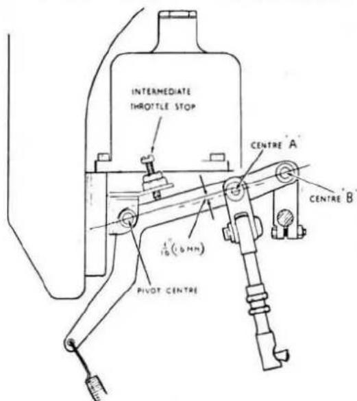
Fig.3.15. Throttle control linkage setting HD6 carburettor
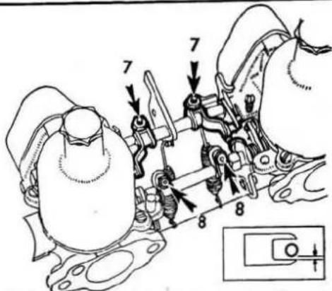
Fig.3.16. Throttle control linkage setting HS6 carburettor
24 Carburettor HD 6 - dismantling and reassembly
1 Remove the starting carburettor from the carburettor by undoing the banjo bolt (item 42 in Fig.3.13). From this point onwards both front and rear carburettors can be treated in a similar manner.
2 Unscrew the damper and remove it together with its washer.
3 Using a small file or scriber, scratch identification marks on the suction chambers so that they may be fitted together again in their original position.
4 Remove the three suction chamber retaining screws and remove the suction chamber from the body leaving the piston in position. Be careful when lifting off the suction chamber not to apply side loads to the piston otherwise the piston needle may be bent.
5 Lift the piston spring from the piston noting which way round it is fitted.
6 Remove the piston and invert it to allow the oil in the damper bore to drain out. Place the piston in a safe place so that the needle will not be damaged or that the piston roll onto the floor. It is suggested that the piston be placed on the neck of suitable sized jar with the needle inside, so acting as a stand.
7 It is recommended that, unless absolutely necessary, the needle is not separated from the piston. However, if the needle must be removed, slacken the retaining screw in the side of the piston body and remove the needle.
8 Mark the position of the float chamber lid in relation to the body. Undo the cap nut and remove together with the washer. Lift off the float chamber lid.
9 Withdraw the pin from the float chamber lever and remove the lever. The pin is serrated and can be removed in one direction only.
10 Remove the float needle by unscrewing on the brass valve body, use the correct size spanner.
11 The float may be lifted out of the float chamber. Place it in a position where it will not be damaged.
12 Remove the banjo bolt from the base of the front carburettor, this will release the connecting arm for the starting carburettor. Note the fibre and aluminium washers.
13 Remove the four setscrews securing the float chamber to the body. On the front carburettor, these screws also secure the starting carburettor bracket.
14 Separate the float chamber from the body and this will free the jet spring, the jet and diaphragm and the jet housing which may now be lifted away from the body.
15 Unscrew the jet bearing nut and lift out the jet bearing.
16 Unscrew the slow running control valve from the body and collect its neaprene and brass washers, note their positions for reassembly.
17 No further dismantling of the carburettor is necessary, indeed, it is rarely that dismantling beyond paragraph 11 will ever be required.
18 Reassembly is the reverse of the above. Fit new washers throughout. The jet needle must be reassembled in the piston in the manner described in Section 33. The jet must be centred as
described in Section
19 Finally, and before fitting the suction chamber fill the piston damper bore to within 12 " of its top with SAE 20 engine oil. Wipe any spillage off the outside of the piston. After fitting the suction chamber, raise the piston by means of the lifting pin and check that it falls back smartly on to the upper face of the body. Any sluggishness, assuming all other factors to be correct, will probably be due to oil on the outside of the piston.
25 Carburettor HS 6 - dismantling and reassembly
1 Refer to Fig.3.17.
2 Remove the baffle plate from the inlet nozzle on those carburettors fitted with "push-on" type petrol feed pipe.
3 Thoroughly clean the outside of the carburettor.
4 Mark the relative positions of the suction chamber and the carburettor body.
5 Remove the damper and its washer.
6 Unscrew the three suction chamber retaining screws and lift off the chamber vertically so as not to put any side loads on the piston as may bend the needle.
7 Refer to Fig.3.18.
8 Remove the piston spring and washer (if fitted). Note which way round the spring is fitted.
9 Carefully remove the piston and invert it to allow the oil in the damper bore to drain out. Place the piston in a safe place so that the needle will not be damaged or that the piston will roll onto the floor. It is suggested that the piston be placed on the neck of a suitably sized jar with the needle inside, so acting as a stand.
10 It is recommended that, unless absolutely necessary, the needle is not removed from the piston. However, if the needle must be removed, slacken the retaining screw on the side of the piston and remove the needle. If the needle cannot easily be removed, tap the needle inwards first and then pull outwards. Do not bend the needle.
11 If a piston lifting pin with an external spring is fitted, remove the spring retaining circlip and spring, then push the lifting pin upwards to remove it from its guide. With the concealed spring type, press the pin upwards, detach the circlip from its upper end, and withdraw the pin and spring downwards.
12 Refer to Fig.3.19.
13 Support the moulded base of the jet and slacken the screw retaining the jet pick-up link.
14 Relieve the tension of the pick-up lever spring from the screw and remove the screw and brass bush (when fitted).
15 Unscrew the brass sleeve nut retaining the flexible jet tube to the float chamber and withdraw the jet assembly from the carburettor body. Note the gland, washer and ferrule at the end of the jet tube.
16 Remove the jet adjusting nut and screw. Unscrew the jet locking nut and detach the nut and jet bearing. Withdraw the bearing from the nut, noting the brass washer under the shoulder of the bearing.
17 Refer to Fig.3.20.
18 Note the location points of the two ends of the pick-up lever return spring. Unscrew the lever pivot bolt together with its double coil spring washer, or spacer. Detach the lever assembly and return spring.
19 Note the location of the two ends of the cam lever spring and push out the pivot bolt tubes, taking care not to lose the spring. Lift off the cam lever noting the skid washer between the two levers.
20 Refer to Fig.3.21.
21 Slacken and remove the bolt retaining the float chamber to the carburettor body. Note the component sequence with flexibly mounted chambers.
22 Mark the location of the float chamber lid. Remove the lid retaining screws and detach the lid and its gasket complete with the float assembly.
23 Push out the float hinge pin from the end opposite to its serrations and detach the float.
24 Extract the float needle from its seating and unscrew the seating from the lid using the correct sized spanner (a box spanner will be found to be the most suitable tool). Do not distort the seating.
25 Refer to Fig.3.32.
26 Close the throttle and mark the relative position of the throttle disc and the carburettor flange.
27 Unscrew the two disc retaining screws. Open the throttle and ease out the disc from its slot in the throttle spindle. The disc is oval and will jam if care is not taken.
28 Tap back the tabs of the tab washer securing the spindle nut. Note the location of the lever arm in relation to the spindle and carburettor body, remove the nut and detach the arm.
29 Reassembly is the reverse of the above. Fit new washers throughout. The jet needle must be assembled in the position in the manner described in Section 33. The jet must be centred as described in Section 32.
30 Finally, and before fitting the piston damper, top up the piston damper tube with SAE 20 oil until the level is 12'' (12.7 mm) above the top of the piston rod.
26 Carburettor SU - examination and repair
The SU carburettor, generally speaking is most reliable and it is very rarely that you would have to completely dismantle it in the manner described in Section 24 and 25. However, after a long period of use some deterioration must be expected, therefore, when the time arrives for a major overhaul of the engine, serious consideration should be given to replacing the carburettors with factory reconditioned items. The carburettor may develop one or more of several faults which may not be readily apparent without careful examination. The common faults to which the carburettor is prone are:-
1 Piston sticking.
2 Float needle sticking.
3 Float chamber flooding.
4 Water and dirt in the carburettor.
In addition the following parts are susceptible to wear after high mileage and as they will affect fuel consumption they should be checked and rectified at, say every other 10,000 mile servicing. a) The carburettor needle: if the carburettor has not been correctly assembled at some time so that the needle has not been truly central in the jet orifice it will be found that the needle will have a tiny ridge on it. If this is noted, the needle must be replaced with one of a similar type (identification letters are stamped on the flat of the needle). As the needles are made to very fine tolerances, no attempt should be made to clean out the ridge or to rub down the needle with emery cloth. If the needle requires cleaning this can be done by rubbing very lightly with metal polish.
b) The carburettor jet: If the needle is worn it is likely that the rim of the jet will be damaged where the needle has been striking it. It should be renewed as wear in the jet will result in high fuel consumption. The jet may also become worn or ridged on the outside where it has been sliding up and down between the jet bearing every time the choke is pulled out. Renewal is the only remedy.
c) The edges of the throttle and the choke tube may become worn. Renew as necessary.
d) The washers fitted to the base of the jet and under the float chamber lid may deteriorate and leak after long use and result in fuel leakage.
e) After high mileage the float chamber needle and seat may become ridged and if this occurs, flooding of the float chamber becomes a distinct possibility. Renew both the needle and the brass seating.
27 Carburettor SU - piston sticking

FIG. 3.17. DISMANTLING THE HS6 CARBURETTOR - STAGE 1
1 Baffle plate
2 Inlet nozzle
3 Suction chamber
4 Carburettor body
5 Marks for replacement
6 Damper 7 Damper washer 8 Chamber retaining screws 9 Direction of removal
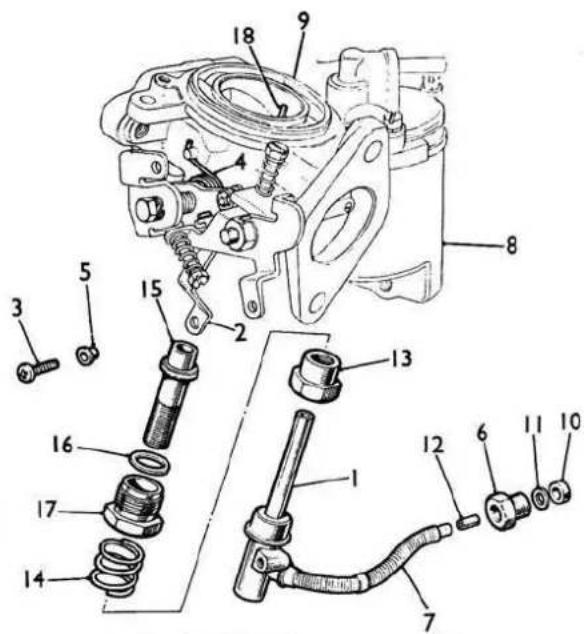
FIG. 3.19. DISMANTLING THE HS6 CARBURETTOR - STAGE 3
1 Jet assembly
2 Pick-up link
3 Link retaining screw
4 Pick-up lever return spring
5 Brass bush
6 Sleeve nut
7 Flexible jet tube
8 Float chamber
9 Carburettor body
10 Gland
11 Washer
12 Ferrule
13 Jet adjusting nut
14 Spring for nut
15 Jet bearing
16 Brass washer
17 Jet locking nut
18 Piston key
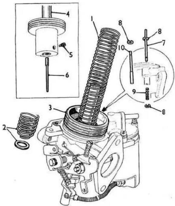
FIG. 3.18. DISMANTLING THE HS6 CARBURETTOR - STAGE 2
1 Piston spring
2 Alternative spring with
washer
3 Piston assembly
4 Piston rod
5 Needle locking screw
6 Needle
7 Piston lifting pin
8 Circlip for pin
9 Spring for pin
10 Alternative lifting pin

FIG. 3.20. DISMANTLING THE HS6 CARBURETTOR - STAGE 4
1 Pick-up lever
2 Lever return spring
3 Lever pivot bolt
4 Double coil spring washer
5 Spacer (alternative)
6 Cam lever
7 Lever spring
8 Pivot bolt tube
9 Skid washer
10 Cam lever spring location
11 Pick-up lever spring location

FIG. 3.21. DISMANTLING THE HS6 CARBURETTOR - STAGE 5
1 Float chamber
2 Retaining bolt
3 Float chamber lid
4 Marks for replacement
5 Lid retaining screws
6 Lid gasket
7 Float
8 Float hinge pin
9 Float needle
10 Needle seating
11 Alternative float chamber
12 Alternative spacers
contact with the suction chamber.
2 Corrosion of the piston rod is not uncommon and this will prevent free movement of the piston. The corrosion can be cleared by careful rubbing with metal polish or, in extreme cases, by very light rubbing with 00 crocus paper.
3 Check that the rim of the piston is not burred as the result of a knock or having been dropped. Burrs can be removed by rubbing with fine emery cloth.
4 After high mileage wear in the centre guide tube may allow the piston to touch the wall of the suction chamber and this will cause obstruction to free movement of the piston.
5 Great care should be taken to remove only the minimum amount of metal when freeing the piston as the parts are made to very fine tolerances and too large a gap will cause air leakage and ill upset the function of the carburettor. Clean down the walls of the suction chamber and the piston rim and ensure there is no oil on them. A trace of light oil may be applied to the piston rod.
6 If the piston is sticking, under no circumstances try to clean it by stretching the return spring.
28 Carburettor SU - float needle sticking
1 If the float needle sticks, the carburettor will soon run dry and the engine will stop.
The easiest way to check for a sticking needle is to disconnect the fuel inlet pipe to the carburettor, check that the gear lever is in "neutral" or, for automatic transmission that it is in "N" or "P", guide the fuel pipe into a wad of rag or into a container, and press the starter solenoid button. If fuel is passed, the fault is almost certainly a sticking needle.
2 Remove the float chamber lid, dismantle the needle valve and clean the housing and float chamber thoroughly.
29 Carburettor SU - float chamber flooding
If fuel emerges from the small breather hole in the cover of the float chamber this is known as flooding. It can be caused by
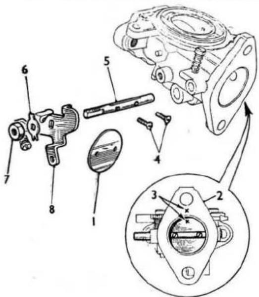
FIG. 3.22. DISMANTLING THE HS6 CARBURETTOR - STAGE 6
1 Throttle disc
2 Carburettor flange
3 Marks for replacement
4 Disc retaining screws
5 Throttle spindle
6 Tab washer
7 Spindle nut
8 Lever arm
the float chamber needle not seating properly in its housing and this is usually due to a piece of dirt or foreign matter which has passed the filters and has become jammed between the needle and its seating in the housing. Alternatively the float may have developed a leak so that it is not rising to operate the float needle lever, this fault can be determined by removing the float and shaking it, any sound of liquid inside the float indicates that it is faulty.
It may be that the setting of the float needle lever in relation to the float chamber cover, is incorrect. Refer to Fig 3.23 in the case of the HD 6 carburettor. The lever clearance should be as shown (use the shank of a 7/16" drill as the test bar) when the lever is lightly pressed on to the needle. If adjustment is required, hold the flat portion with a pair of pliers and bend only at the positionshown. In the case of HS 6 carburettors refer to Fig.3.24. The clearance indicated by the arrow should be 1/8" to 3/16" (3.2 to 4.8 mm) when the needle valve is held in the shut-off position by the weight of the float only. The clearance is adjusted by bending at the crank.
30 Carburettor SU - water or dirt in the carburettor
1 Because of the size of the jet orifice, water or dirt in the carburettor is usually self clearing with only a momentary noticeable affect on the engine performance. However, if dirt in the carburettor is suspected, lift the piston and flood the float chamber. The normal level of the fuel should be about 1/16" below the top of the jet so that on flooding the carburettor the fuel should flow out of the jet hole.
2 If little or no petrol appears, start the engine (because of the needle, the jet will never be completely blocked) and with the throttle fully open place your hand over the air intake, leave in position momentarily and then remove it. The vacuum caused by this action will help suck out any foreign matter, repeat this procedure two or three times and then check for flow of fuel as described in the first paragraph of this Section.
3 In the event of the above action failing to clear the jet (and this is unlikely) you will have to remove and blow out the jet.
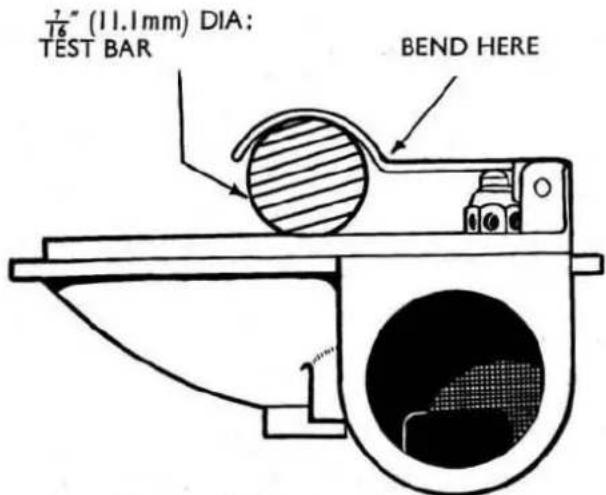
Fig.3.23. Checking the float lever setting HD6 carburettor
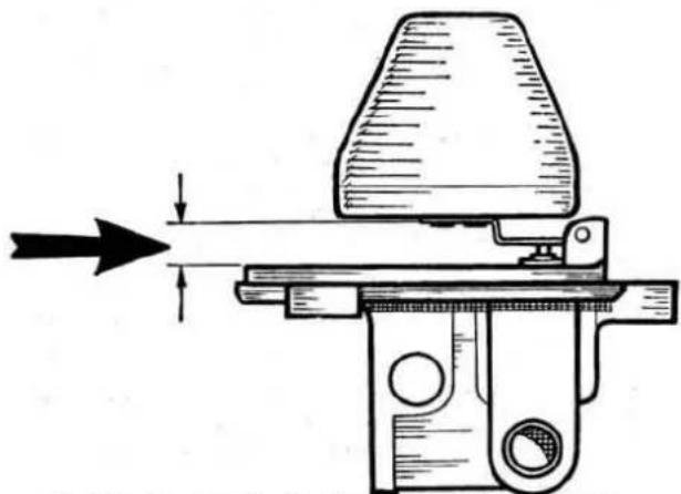
natural_image
Technical line drawing of a mechanical device with directional arrows indicating motion or force (no text or symbols)Fig.3.24. Checking the float lever setting HS6 carburettor
31 Carburettor HD 6 - jet centring
Warning: Take care not to bend the needle when carrying out this operation.
1 Remove the carburettor from the engine as described in Section 23.
2 Remove the piston damper.
3 Remove the four setscrews securing the float chamber to the carburettor body, detach the float chamber and remove the jet housing and the jet.
4 Using a ring spanner, slacken the jet locking nut approximately half a turn.
5 Refer to Fig.3.15. Replace the jet and diaphragm assembly. Push the jet and diaphragm assembly as high as possible with hand pressure and at the same time press the piston down onto the jet bridge, using a pencil or a piece of rod for this. Centralisation will be helped by lightly tapping on the side of the carburettor body.
6 Tighten the jet locking nut.
7 The actual centring must be carried out with the setscrew holes in the jet diaphragm and carburettor in alignment. After tightening the jet locking nut the jet diaphragm must be kept in the same position relative to the carburettor body and to do this it is advisable to mark one of the corresponding jet diaphragm and carburettor setscrew holes with a soft pencil. Centring will be upset if the diaphragm is moved radially after tightening the jet nut.
8 The jet is correctly centred when the piston falls freely and
hits the jet "bridge" with a metallic click. Check if there is any difference in the sound of the piston hitting the bridge with the jet in its highest and lowest positions. If there is any difference in the sound, the procedure for centralising the jet will have to be repeated.
9 If difficulty in centring the jet is encountered after carrying out above procedure, it is permissible to lower the jet needle slightly in the position to make centralising more positive. The needle must, however, be restored to its normal position when checking the centralisation.
10 Top up the damper with SAE 20 engine oil.

natural_image
Technical illustration of a mechanical assembly with hands operating a tool (no text or symbols present)Fig.3.25. Centring the jet HD6 carburettor
32 Carburettor HS 6 - jet centring
Warning: Take care not to bend the needle when carrying out this operation.
1 Remove the carburettor from the engine as described in Section 23.
2 Remove the piston damper.
3 Remove the jet head screw to release the control linkage.
4 Refer to Fig.3.26. Withdraw the jet, disconnecting the fuel feed pipe union in the float chamber and removing the rubber sealing washer.
5 Remove the jet locking spring and adjusting nut.
6 Replace the jet and insert the fuel feed pipe connections into the float chamber.
7 Slacken the jet locking nut until the assembly is free to rotate.
8 Apply pressure to the top of the piston rod using a pencil or a piece of rod.
9 Tighten the jet locking nut at the same time keeping the jet hard up against the jet bearing.
10 The jet is correctly centred when the piston falls freely and hits the jet bridge with a metallic click. Check if there is any difference in the sound of the piston hitting the bridge with the jet in its highest and lowest position. If there is any difference in the sound the procedure for centralising the jet will have to be repeated.
11 If difficulty in centring the jet is encountered, it is permissible to lower the needle slightly in the piston to centralisation. The needle must be restored to its normal position for checking the centralisation.
12 Refit the jet locking spring when centralisation is correct. Before replacing the fuel feed pipe line into the float chamber fit the rubber sealing washer over the end of the plastic pipe so that at least 3/16" (4.8 mm) of pipe protrudes (see inset, Fig.3.26).
13 Top up the damper with SAE 20 engine oil.
33 Carburettor SU - needle replacement
The needle size is determined during engine development and
will provide the correct mixture strength unless extremes of temperature, humidity or altitude are encountered. A different needle to that specified may be required if any alteration to the standard specification of the exhaust system, air cleaner, camshaft or compression ratio is made.
1 Remove the suction chamber and piston assembly.
2 Slacken the needle clamping screw in the side of the body of the piston and pull out the old needle. If the needle is tight it can probably be loosened by moving it inwards and then pulling out.
3 The needle type letter is stamped on the shank of the needle, check that this corresponds with the item being fitted.
4 Fit the needle to the piston assembly so that it is positioned as shown in Fig.3.27. Another type of needle, not illustrated, has a groove instead of the shoulder depicted, the correct position for this type of needle is for the bottom edge of the groove to be level with the bottom edge of the piston rod.
5 Correct positioning of the needle in relation to the piston is essential otherwise the fuel/air mixture to the engine will be upset.

natural_image
Mechanical assembly diagram showing a hand adjusting a cylindrical component with attached springs and bolts, plus an inset view of the assembly (no text or labels present)Fig.3.26. Centring the jet HS6 carburettor

Fig.3.27. Location of the jet needle in the piston
34 Carburettors SU - adjustment and tuning - general
It is useless to attempt carburettor tuning until the cylinder compressions, valve clearances, spark plug gaps and contact breaker gaps have been tested, checked and adjusted as necessary. The distributor centrifugal advance mechanism and vacuum advance operation should be checked and ignition timing set to the correct figure. The ignition timing is important since if retarded or advanced too far the setting of the carburettors will be affected. Ensure that the needles are correctly located in the pistons (see Section 33). Check over the carburettors and ensure that the pistons are free in the suction chambers and that the piston dampers are topped up with engine oil SAE 20. Lubricate the throttle controls and check for free operation and travel. Check that petrol filters are clean.
35 Carburettors SU HD 6 - adjustment and tuning
Only two adjustments are provided at the carburettor as illustrated in Fig.3.28. These are (a) the slow running volume screw "A" and (b) the mixture adjusting screws "B" governing the idling speed and the mixture strength respectively. The design of the SU carburettor is such that correct mixture strength at idling speed ensures that the carburettors are correctly adjusted throughout their entire range.
1 Remove the air cleaner and air intake pipe.
2 Remove the suction chambers from the carburettors and screw out both mixture screws (B) until the tops of the jets are flush with the jet bridge in each carburettor body.
3 Screw in the mixture screws until the jets start to move and then screw in a further 3½ turns. Replace the pistons and suction chambers.
4 Slacken one clamp bolt on the coupling between the throttle spindles. Check that both butterfly valves are closed by rotating both throttle spindles clockwise when viewed from the front. Tighten the coupling clamp bolt.
5 Screw in the slot running volume screws (A) until they meet their seatings and then unscrew each of the screws 2½ turns.
6 Start the engine and run until it reaches its normal operating temperature.
7 Now the carburettors must be balanced (synchronised) by adjusting on the slow running volume screws (A) until they are sucking equally. This can best be judged by applying a balance meter to the carburettor air inlet and adjusting on the screws until the readings are the same. Alternatively, listen to the "hiss" of each carburettor (use a piece of tube as illustrated in Fig.3.29, a piece of old bicycle tube is ideal and adjust on each of the screws (A) until it is judged that the hiss from each carburettor is the same.
8 Keep checking as above and continue adjusting on the slow running volume screws until, with the carburettors balanced (same hiss), the engine is idling at 500 rpm on cars fitted with the 3-speed synchromesh gearbox or automatic transmission and at 700 rpm on cars fitted with the all synchromesh gearbox.
9 Re-check that both butterfly valves are fully closed by rotating the throttle spindles in a clockwise direction looking from the front, and noting if any change in engine speed results, there should be no change in engine speed if the butterflies are indeed closed.
10 Now refer to Fig.3.30 and check the mixture strength by lifting the piston of the front carburettor approximately 1/32" (0.8 mm) by means of the lifting pin (arrowed), if:-
a) the engine speed increases appreciably this indicates that the mixture strength of the front carburettor is too rich.
b) the engine speed immediately decreases, this indicates that the mixture strength of the front carburettor is too weak.
c) the engine speed increases slightly and continues to run without change of speed, then the mixture strength of the front carburettor is correct.
11 Repeat the above operation for the rear carburettor to test its mixture strength and after adjustment recheck the front carburettor as the two carburettors are interdependant.
12 A check on the correctness of the mixture adjustment is to listen to the exhaust note:-
a) an irregular note, splashy misfire and colourless emission indicates that the mixture is too weak.
b) a regular or rhythmical misfire and the emission of black smoke indicates that the mixture is too rich.
c) a regular and even note indicates that the mixture is correct. 13 To enrich the mixture, screw in the adjustment screw (B) clockwise and to weaken the mixture, unscrew it anti-clockwise. 14 Some adjustment of the slow running to maintain the desired 500 or 700 rpm may now be required following adjustment of the mixture strength. To do this, rotate each screw (A) exactly the same amount and listen at the air intake (or apply the meter) to maintain balance.
15 Replace the air cleaner and air intake pipe.
16 Re-check the mixture strength as described in paragraph 10.
36 Carburettors SU HS 6 - adjustment and tuning
1 Remove the air cleaner and the air intake elbow.
2 Remove the suction chamber and piston from each carburettor.
3 Disconnect the mixture control wire.
4 Screw the jet adjusting nut upwards until the jet is flush with the bridge of the carburettor or fully up if this position cannot be obtained but the position of both jets must be the same.
5 Replace the piston and suction chamber. Check that the piston falls freely onto the bridge when the lifting pin is released.
6 Turn down the jet adjusting nut two complete turns.
7 Unscrew the throttle adjusting screws ("A" in Fig.3.31) until they are just clear of their stops and then screw down 1 12 turns open.

Fig.3.28. HD6 carburettor adjustment

natural_image
Line drawing of a person using a mechanical device with a tool, no text or symbols presentFig.3.29. Balancing the S.U. carburettor
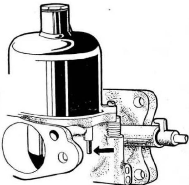
natural_image
Technical line drawing of a mechanical assembly with no visible text or symbolsFig.3.30. The piston lifting pin

Fig.3.31. Adjustment of the HS6 carburettor
8 Slacken both of the clamping bolts on the throttle spindle interconnections.
9 Disconnect the jet control interconnection by slackening the clamping bolts.
10 Unscrew the fast idle adjusting screws until they are clear of their stops.
11 Start the engine and run until it attains its normal operating temperature.
12 Adjust on each throttle adjusting screw by the same amount each to give the desired idling speed.
13 Now the carburettors must be balanced (synchronised) by adjusting the throttle adjusting screws until they are sucking equally. This can best be judged by applying a balance meter to the carburettor air inlet and adjusting the screws until the readings are the same. Alternatively, listen to the "hiss" of each carburettor (use a piece of tube as illustrated in Fig.3.29, a piece of old bicycle tube is ideal) and adjust on each of the screws until it is judged that the hiss from each carburettor is the same.
14 Check the mixture strength of the front carburettor (see Fig.3.30) by raising the piston about 1/32" by means of the lifting pin, if:-
a) the engine speed increases appreciably, this indicates that the mixture of the front carburettor is too rich.
b) the engine speed immediately decreases, this indicates that the mixture strength of the front carburettor is too weak.
c) the engine speed increases slightly and continues to run without change of speed, then the mixture strength is correct.
15 Repeat the above operation for the rear carburettor and after adjustment recheck the front carburettor as the two carburettors are interdependant.
16 A check on the correctness of the mixture adjustment is to listen to the exhaust note:-
a) An irregular note, splashy misfire and colourless emission indicates that the mixture is too weak.
b) a regular or rhythmical misfire and the emission of black smoke indicates that the mixture is too rich.
c) a regular and even note indicates that the mixture is correct.
17 To enrich the mixture, screw down on the jet adjusting nut (anti-clockwise) and to weaken the mixture screw up on the nut (clockwise).
18 Some adjustment of the slow running may now be required following adjustment of the mixture strength. To do this, adjust each throttle adjusting screw the same amount at the same time checking by hiss or by the meter that they remain in balance.
19 Set the throttle interconnecting clamping levers (item 7 in Fig.3.16) so that the link pin is 0.006" (0.15 mm) away from the lower edge of the fork as shown in the inset to Fig.3.16. Tighten the clamp bolts.
20 With the jet levers at their lowest position set the jet interconnection lever clamp bolts, 8 in Fig.3.16, so that both jets commence to move simultaneously.
21 Reconnect the mixture control wire with about 1/16" (1.6 mm) free movement before it starts to move the jet levers.
22 Operate the mixture control lever in the car until the linkage is about to move the carburettor jets and then adjust the fast idle screws, comparing the intensity of the air intake "hiss", to give an engine speed of about 1000 rpm when hot.
23 Refit the air cleaner and the air intake elbow to the carburettors and recheck for correct mixture as described in paragraph 14.

Fig.3.32. The auxiliary starting carburettor
37 The auxiliary starting carburettor - description
The auxiliary starting carburettor, is attached to the float chamber of the front HD 6 carburettor of the 3.4, 3.8 litre and 340 models, the parts forming the assembly to the carburettor are shown in Fig.3.32. It is a device for automatically enriching the mixture when starting from cold and is brought into action by a solenoid energised by a thermostatic switch located in the inlet manifold water jacket.
Fuel from the float chamber is supplied to the base of the jet (9) the size of which is governed by the position of the sliding needle (10) which is moved against the spring (11) by inlet manifold depression acting on the disc (12) attached to the shank of the needle. After passing the jet, the fuel is mixed with air drawn in from the intake (7) through the passage (8), the mixture is drawn past the needle into the passage (14) and thence, if the valve (3) is clear of its seating (2), into the inlet manifold. The thermostatic switch is connected to the solenoid through the terminal (6) and when the winding of the solenoid (5) is energised, the iron core (4), to which the valve is connected, is lifted thus allowing free passage of the mixture. When
the engine attains its normal running temperature the switch operates and de-energises the magnet to allow the valve to close.
38 The auxiliary starting carburettor - adjustment
1 Tuning of this device is confined to adjustment of the stop screw (13) which limits the downward travel of the needle (10).
2 Run the engine until it attains its normal running temperature.
3 Energise the solenoid by shorting the terminal of the thermostatic switch directly to earth with a screwdriver and at the same time flick open the throttles when the carburettor will be heard to come into operation with a pronounced hissing noise.
4 Adjust the stop screw (13) until the mixture is distinctly, but not excessively, rich ie until the exhaust gases are seen to be discernably black in colour, but just short of the point where the engine commences to run noticeable irregularity.
5 Anti-clockwise rotation of the stop screw will raise the needle and enrichen the mixture and screwing down on the screw will weaken the mixture.
39 The thermostatic switch - removal and refitting
The thermostatic switch which controls the operation of the auxiliary starting carburettor is situated at the front end of the inlet manifold water jacket, it operates the solenoid of the starting carburettor at temperatures below 30 - 35°C. It cannot be dismantled so if any fault arises there is no alternative but to fit a new item.
1 Disconnect the battery as a safety measure.
2 Drain sufficient water from the radiator to clear the inlet manifold water jacket.
3 Disconnect the electrical lead from the switch by undoing the chrome dome nut.
4 Remove the three securing setscrews and washers and withdraw the switch and the cork gasket.
5 Refitting is the reverse of the removal procedure but a new cork gasket must be fitted.
6 Top up the radiator to the correct level.

natural_image
Exploded view diagram of a mechanical assembly showing bolt, nut, and clamp components (no text or labels)Fig.3.33. The auxiliary starting carburettor thermostatic switch
40 Fault diagnosis
Unsatisfactory engine performance is not necessarily the fault of the fuel system or the carburettors. Indeed, sluggishness, excessive fuel consumption etc: more commonly occur as the result of ignition faults so, before spending time in trying to trace a suspected fuel or carburation fault, it is advisable to first refer to Chapter 4 and check over the ignition system. The table below, therefore, assumes that the ignition system has been checked and is in order; the table should also be read in conjunction with Sections 7,15 to 21 and 26 to 30 of this Chapter.
| Symptom | Reason/s | Remedy |
| Smell of petrol when engine is stopped | Leaking fuel lines or unionsLeaking fuel tank | Repair or renew as necessary.Fill fuel tank to capacity and examine carefully at seams, unions and filler pipe. Repair as necessary. |
| Smell of petrol when engine is idling | Leaking fuel line unions between pump and carburettorOverflow of fuel from float chamber due to wrong level setting or ineffective needle valve or punctured float | Check line and unions, tighten and repair.Check fuel level setting and condition of float and needle valve, renew as necessary. |
| Excessive fuel | Worn needle | Renew needles. |
| Consumption for reasons not covered by leaks or float chamber faults | Sticking needle | Check correct movement of needle body. |
| Difficult starting, uneven running, lack of power, cutting out | One or more blockagesFloat chamber fuel level too low or needle sticking | Check fuel lines and clear.Dismantle and check. |
Fuel pump not delivering sufficient fuel
Intake manifold gaskets leaking or manifold cracked
Check pump delivery and clean or repair as required.
Check tightness of securing nuts and inspect manifold.
Chapter 4 Ignition system
Contents
| General description | ... | ... | ... | ... | ... | ... | 1 |
| Contact breaker points - removal and replacement | ... | ... | ... | ... | ... | ... | 2 |
| Contact breaker points - adjustment | ... | ... | ... | ... | ... | ... | 3 |
| Condenser - removal, testing and replacement | ... | ... | ... | ... | ... | ... | 4 |
| Distributor - lubrication | ... | ... | ... | ... | ... | ... | 5 |
| Distributor - removal and replacement | ... | ... | ... | ... | ... | ... | 6 |
| Distributor - dismantling | ... | ... | ... | ... | ... | ... | 7 |
| Distributor - inspection and repair | ... | ... | ... | ... | 8 |
| Distributor - reassembly | ... | ... | ... | ... | 9 |
| Ignition timing ... | ... | ... | ... | ... | 10 |
| Sparking plugs and leads | ... | ... | ... | ... | 11 |
| Ignition system - fault finding | ... | ... | ... | ... | 12 |
| Fault diagnosis - engine fails to start | ... | ... | ... | ... | 13 |
| Fault diagnosis -engine misfires | ... | ... | ... | ... | 14 |
Specifications
| 2.4 | 3.4 |
| L7 (or L10S) | L7 (or L10S) |
| N5 (or NA8) | N5 (or NA 8) |
| — | N5 (or NA 8) |
| 0.030 in (0.76 mm) | 0.025 in (0.64 mm) |
| N5 | UN12Y |
| N5 | UN12Y |
| — | UN12Y |
| 0.025 in (0.64 mm) | 0.025 in (0.64 mm) |
0.025 in (0.64 mm)
| N5 |
| 0.025 in (0.64 mm) |
| UN12Y |
| 0.025 in (0,64 mm) |
| 1, 5, 3, 6, 2, 4(no 1 cylinder at rear of engine) |
Distributor
| Make ... ... Serial no. and type | ... ... ... ... ... ... ... |
| 2.4 Mk 1 | 7:1 comp: ratio ... ... ... |
| 8:1 comp: ratio ... ... ... ... | |
| 3.4 Mk 1 | 7:1 comp: ratio ... ... ... ... |
| 8:1 comp: ratio ... ... ... ... | |
| 9:1 comp: ratio ... ... ... ... | |
| 2.4 Mk 2 | 7:1 comp: ratio ... ... ... ... |
| 8:1 comp: ratio ... ... ... ... | |
| 3.4 Mk 2 | 7:1 and 8:1 comp: ratio ... ... ... |
| 9:1 comp: ratio ... ... ... ... |
Lucas
| 40557/A - DMBZ6A |
| 40528/A - DMBZ6A |
| 40578/A - DMBZ6A |
| 40576/A - DMBZ6A |
| 40617/A - DMBZ6A |
| 40557/A - DMBZ6A |
| 40528/B - DMBZ6A to engines BG 9999 and BH 8936 |
| 40884/A - 22D6 engine BH 8937 onwards |
| 40640/A - DMBZ6A to engines KG 9999 and KH 8332 |
| 40885/A - 22D6 to engines KH 9999 and KJ 6897 |
| 41063/A - 22D6 engine KJ 6898 onwards |
| 41064/A - 22D6 |
| 3.8 litre | 7:1 and 8:1 comp: ratio ... ... | 40640/A - DMBZ6A to engines LA 9999, LB 9999, LC 535440885/A - 22D6 to engines LC 9999, LE 204641063/A - 22D6 engine LE 2047 onwards | |||||||
| 9:1 comp: ratio ... ... ... | 40665/A - DMBZ6A | ||||||||
| 240 models | 8:1 comp: ratio ... ... ... | 41208/B - 25D6 | |||||||
| 340 models | 8:1 comp: ratio ... ... ... | 41063/A - 22D6 | |||||||
| 9:1 comp: ratio ... ... ... | 41064/A - 22D6 | ||||||||
| Note: - 22D6 distributors are a replacement for the DMBZ6A type | |||||||||
| Cam dwell angle ... ... ... ... ... ... | 35^ ± 2^ | ||||||||
| Contact breaker gap ... ... ... ... ... | 0.014 - 0.016 in (0.36 - 0.41 mm) | ||||||||
| Contact breaker spring tension (measured at free contact) | 18 - 24 ozs (512 - 682 gms) | ||||||||
| Static ignition timing | |||||||||
| Mk 1 models 2.4 | 7:1 comp: ratio ... ... ... | 4^ BTDC (1 1/3 flywheel teeth) | |||||||
| 8:1 comp: ratio ... ... ... | 6^ BTDC (1 3/4 flywheel teeth)with 40528A - DMBZ6A distributor the timing is 1^ BTDC = 1/3flywheel teeth. | ||||||||
| 3.4 | 7:1 comp: ratio ... ... ... | TDC | |||||||
| 8:1 comp: ratio ... ... ... | 2^ BTDC (2/3 flywheel teeth) | ||||||||
| 9:1 comp: ratio ... ... ... | TDC | ||||||||
| Mk 2 models and 240/340 | 2.4 | 3.4 | 3.8 | ||||||
| Type of air cleaner | Oil bath | Oil bath | Paper element | Oil bath | Paper element | ||||
| TDC | TDC | TDC | TDC | ||||||
| 6^ BTDC | 2^ BTDC | 7^ BTDC | 4^ BTDC | 7^ BTDC | |||||
| 8^ BTDC | TDC | 5^ BTDC | 10^ BTDC | 5^ BTDC | |||||
| — | |||||||||
| 240 model ... ... ... ... ... ... | 12^ BTDC | ||||||||
| 340 model ... ... ... ... ... ... | 10^ BTDC | ||||||||
1 General description
The ignition system is based on the supply of low tension voltage from the battery to the ignition coil it is converted into high tension voltage. The high tension voltage is powerful enough to jump the spark plug gap in the cylinders under high compression pressures providing that the ignition system is in good working order and that all adjustments are correct.
The ignition system comprises two individual circuits known as the low tension (LT) and the high tension (HT) circuits. The LT circuit, which is sometimes referred to as the primary circuit, comprises the battery, the lead to the control box, the lead to the ignition switch and from there to the low tension or primary coil windings of the coil (terminal SW), and the lead from the low tension coil windings (terminal CB) to the contact breaker points and condenser in the distributor.
The HT circuit consists of the high tension or secondary coil windings, the heavy ignition lead from the centre of the coil to the centre position in the distributor cap and thence via a carbon brush to the rotor arm and then through the spark plug leads to the spark plugs.
The system functions as follows. Low tension voltage is changed in the coil into high tension voltage by the opening and closing of the contact breaker points in the low tension circuit. HT voltage is then fed via the carbon brush in the centre of the distributor cap to the rotor arm of the distributor. The rotor arm revolves inside the distributor cap and each time it comes into line with one of the six metal segments in the cap, which are connected to the spark plug leads, the opening and closing of the contact breaker points causes the HT voltage to build up, jump the gap from the rotor arm to the appropriate metal segment and so via the lead to the spark plug, where it finally jumps the spark plug gap before going to earth. The contact breaker points consist of one fixed and one free point. The free point bears on the shaft which carries the rotor arm and movement of this point is governed by the shape of the shaft which is hexagonal at the position where the point bears. As the shaft revolves, the free contact breaker point moves over one of the humps of the hexagon and is so brought out of contact with the fixed point.
The ignition is advanced and retarded automatically to ensure that the spark occurs at the right moment for the particular load at the prevailing engine speed.
The ignition advance is controlled both mechanically and by
a vacuum operated system. The mechanical system comprises two lead weights, which act in the same manner as a governor, and which, due to centrifugal force, move out from the distributor shaft as the engine speed rises. As they move outwards they rotate a cam relative to the distributor shaft and so advance the spark. The weights are held in position by two light springs and it is the tension of the springs which is largely responsible for correct spark advancement.
The vacuum control consists of a diaphragm, one side of which is connected via a small bore tube to the inlet manifold and the other side to the contact breaker plate. Depression in the inlet manifold, which varies with engine speed and throttle opening, causes the diaphragm to move carrying with it the contact breaker plate and thus advancing or retarding the spark. A fine degree of control is achieved by a spring in the vacuum assembly. It will be seen from the Specification at the beginning of the Chapter that the type of distributor used varies with the model of the car. There is little or no outward difference in any of them and the above description and the following Sections apply to each of the types.
2 Contact breaker points - removal and replacement
1 If the contact breaker points are burned, pitted or badly worn, they must be replaced.
2 To remove the points first spring back the two clips (one at each side) holding the distributor cap to the body of the distributor. Lift off the cap and place it so that it is held clear of the distributor. Remove the rotor arm.
3 Unscrew the terminal nut securing the spring loaded free contact breaker arm. Remove both leads from the stud and the top insulating bush.
4 Lift off the contact breaker arm and remove the large fibre washer from the terminal pin.
5 Remove the two screws, in the case of the DMBZ6A distributor, or the single screw in the case of the 22D6 and 25D6 distributors, which hold the adjustable breaker arm and remove it.
6 If the contact points are dirty or are pitted they may be polished by use of a fine carborundum stone but it is essential that the faces are kept square and flat. Wipe away all dust after cleaning using a non-fluffy cloth moistened in petrol.
7 If a new set of points is being fitted it is essential that the
faces of the points are thoroughly cleaned with a non-fluffy cloth moistened in petrol in order to remove the preservative which will have been applied to them.
8 To replace the points, first position the adjustable contact breaker plate and secure it with its screw (s) and spring and flat washer.
9 Fit the large fibre washer to the terminal pin and then, bending the spring of the free contact breaker arm between the thumb and two fingers, fit the fibre of the arm to its pin and the eye of the spring to the terminal pin.
10 Insert the flanged nylon bush over the terminal pin and into the eye of the spring with the condenser lead immediately under its head and the low tension lead under that. Fit the steel washer and screw on the securing nut.
11 It is important to use the correct sized spanner for the nut and the correct sized screwdriver for the screws otherwise there is a possibility of these becoming "chewed-up" and making subsequent removal or replacement, difficult.
12 The gap of the contact breaker points must now be adjusted as described in the following Section.
3 Contact breaker points - adjustment
1 Remove the distributor cap and the rotor arm. If the rotor arm is difficult to move, it is permissible to lever on it, gently and evenly, with a screwdriver.
2 Remove the spark plugs to facilitate turning the engine to bring it to the required position.
3 Rotate the engine (by pulling on the fan belt or by using a spanner on the crankshaft damper securing nut) until the neck of the fibre body of the spring loaded contact breaker arm is on the peak of one of the hexagonal lobes of the distributor shaft.
4 Measure the gap between the contact breaker points. It should be 0.14" to 0.16" (0.36 to 0.41 mm). The gap must be adjusted if outside of those limits.
5 Refer to Fig.4.1 which illustrates the DMBZ6A type of distributor. The fixed plate is held by two screws (A) one of which passes through an elongated hole in the plate, Slacken these screws and rotate screw B, which is an eccentric headed adjusting screw, until the correct contact breaker gap is obtained. Now tighten screws "A".
6 Fig.4.2 illustrates the 22D6 and 25D6 type of distributor. Here the means of securing and adjusting the fixed plate is slightly different. The fixed plate is anchored at one end on a pin and is secured by a single screw "A". Slacken screw "A" and enter a screwdriver blade into one of the notches "B", turn the screwdriver to move the plate to obtain the correct gap. Tighten screw "A".
7 It is an elementary point, but do make sure that the blade of your feeler gauge is clean and free of oil because if the contact points are dirtied the result will be no spark at the plug.
8 Replace the rotor arm, the distributor cap and the spark plugs.
4 Condenser - removal, testing and replacement
1 The purpose of the condenser (capacitor) is to ensure that when the contact breaker points are open there is no sparking across them which would waste voltage and cause wear.
2 The condenser is fitted in parallel with the contact breaker points. If it develops a short circuit, it will cause ignition failure as the points will be prevented from interrupting the LT circuit.
3 If the engine becomes difficult to start, or begins to miss after several miles running, and the contact breaker points show signs of excessive burning, then the condition of the condenser must be suspect. A check can be made by separating the points when the ignition is switched "ON"; if this is accompanied by a flash, it is an indication that the condenser has failed.
4 Wihtout special test equipment, the only sure way to diagnose condenser trouble is to replace the suspect item with a new one and see if there is any improvement. Condensers are not expensive.
5 To remove the condenser from the distributor, remove the

FIG.4.1. CHECKING CONTACT BREAKER GAP - DMBZ6A DISTRIBUTOR
A Screws securing fixed contact plate B Eccentric headed adjusting screw
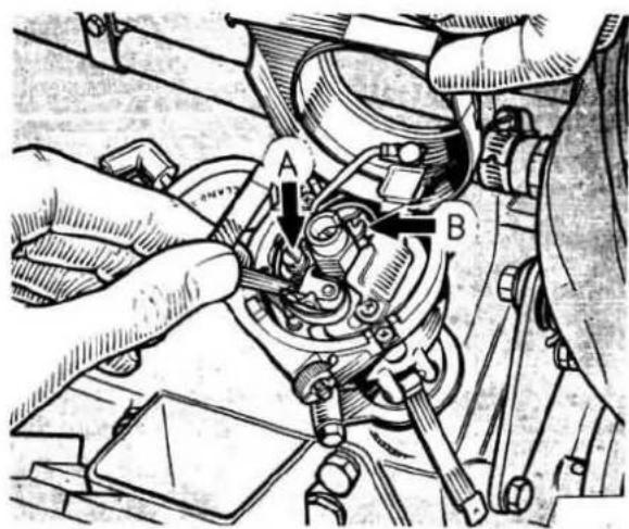
FIG.4.2. CHECKING CONTACT BREAKER GAP-22D6 AND 25D6
A Contact plate securing screw
B Adjusting notches

Fig.4.3. Distributor lubrication points
distributor cap and the rotor arm. Unscrew the contact breaker arm terminal nut, remove the nut and the flanged nylon bush. Remove the condenser lead.
6 Undo the condenser securing screw and lift away the condenser.
7 Replacement of the condenser is a reversal of the above procedure. Take particular care that the condenser lead does not short circuit against any part of the breaker point.
5 Distributor - lubrication
1 The distributor should be cleaned and lubricated periodically (every 2500 miles is recommended). But do not be over lavish with oil and under no circumstances allow it anywhere near the contacts.
2 Remove the distributor cap and the rotor arm.
3 Refer to Fig.4.3.
4 Lubricate the cam bearing by injecting a few drops of thin machine oil into the rotor arm spindle "A". Do not remove or slacken the screw inside the spindle - a space is provided beneath the head of the screw to allow the passage of thin lubricant.
5 Lubricate the post "B" with one drop of oil.
6 Lightly smear the faces of the cam "C" with clean engine oil or vaseline.
7 Lubricate the centrifugal timing control by injecting a few drops of thin oil through a convenient aperture in the contact breaker base plate.
8 Clean the distributor cap inside and out, with a soft dry cloth. Pay particular attention to the spaces between the terminals. Check that the carbon brush in the head of the cap can move freely in its holder. Rough, burned or blackened contacts can be cleaned with a fine carborundum stone or emery cloth. Remove metallic dust after cleaning the contacts by use of a cloth moistened in petrol.
9 Replace the rotor arm and the distributor cap.
6 Distributor - removal and replacement
1 For safety reasons, disconnect the battery.
2 Release the clips securing the distributor cap to the body and lift off the cap.
3 Remove the spark plugs.
4 Slowly turn the engine until the static timing marks coincide (see Section 10) and the rotor arm is pointing to the distributor cap segment which is connected to No.6 spark plug (front plugs).
5 Disconnect the low tension lead from the terminal on the side of the distributor.
6 Detach the vacuum pipe from the distributor advance unit.
7 Undo the screw securing the distributor clamp plate to the cylinder block. Remove the screw and the spring washer. The distributor may now be lifted up with the clamp plate still attached.
8 If it is not wished to disturb the ignition timing, then under no circumstances must the distributor clamp pinch bolt be loosened. Provided the distributor clamp is not moved and the engine is not turned when the distributor can be replaced without losing ignition timing.
9 Replacement is the reverse of the above sequence. If the engine has been turned or the distributor clamp has been disturbed it will be necessary to retime the ignition as described in Section 10.
7 Distributor - dismantling
1 Remove the distributor from the car as described in Section 6.
2 Refer to Fig. 4.4 which shows an exploded view of the distributor.
3 Remove the contact breaker points as described in Section 2 and remove the condenser as described in Section 4.
4 Remove the two screws securing the base plate and earth
lead. Disconnect the link to the vacuum control unit and lift off the base plate.
5 Before proceeding any further, take careful note of the relative positions of the rotor arm slot located above the cam and of the offset driving dog. It is possible to assemble these items 180° out on reassembly which means that the distributor would have to be rotated 180° in order to obtain correct timing of the engine and connections cannot be made with the distributor so located.
6 Remove the cam retaining screw ("A" in Fig.4.3) and remove the cam.
7 Lift out the automatic timing control weights and their springs. Note how these are fitted.
8 Remove the circlip securing the knurled advance and retard adjustment nut. Remove the adjusting nut and spring. The vacuum unit can now be withdrawn.
9 Remove the clamp plate (but see Section 6 paragraph 8) by undoing the pinch bolt and sliding the plate off the base of the distributor.
10 To remove the driving dog, knock out the taper pin and lift off the dog and thrust washer. The shaft may now be lifted upwards.

Fig.4.4. Exploded view of the distributor (type DMBZ6A illustrated)
8 Distributor - inspection and repair
1 Thoroughly wash all mechanical parts in petrol and wipe dry using a clean non-fluffy rag.
2 Check the contact breaker points as described in Section 2.
3 Check the distributor cap for signs of 'tracking' which will be indicated by a thin black line between the segments. Replace the cap if this defect is noted.
4 Examine the contacts in the cap. If they are rough, burned or blackened, clean them with a fine carborundum stone or fine emery cloth. Thoroughly clean the cap after rectification.
5 Ensure that the carbon brush in the cap is free to move in its holder and is not worn down. Do not remove the brush needlessly as the spring is usually a tight fit in the holder and will be badly stretched as you pull the brush out.
6 If the metal portion of the rotor arm is badly burned or is loose, renew the arm. Slight burning can be rectified with a fine file but maintain the face square.
7 Examine the fit of the contact breaker plate on the base plate and check the breaker arm pivot for looseness or wear. Renew the plate if necessary.
8 Examine the centrifugal weights and pivot pins for wear and renew the weights or cam assembly if a degree of wear is found.
9 Examine the shaft and the fit of the cam assembly on the shaft. If the clearance appears to be excessive, compare with new items and renew either or both if they show excessive wear.
10 If the shaft is a loose fit in the distributor bush and can be "rocked", we suggest that a reconditioned distributor is obtained. However, a new bush can be obtained and fitted to the DMBZ6A type of distributor but not to the types 22D6 or 25D6 for which there is no alternative but replacement of the complete distributor. The bearing bush is replaced as follows.
11 Drive out the old bush with a suitable punch.
12 Prepare the new bush for fitting by allowing it to stand completely immersed in a medium viscosity engine oil (SAE30-40) for at least 24 hours. The period of time can be shortened by soaking in oil heated to 100^ for 2 hours.
13 Press the new bush into the distributor body using a shouldered mandrel the shank of which should be approximately 0.0005" greater in diameter than the distributor shaft.
9 Distributor - reassembly
1 Reassembly is a straightforward reversal of the dismantling process. Note in addition:
2 Lubricate the centrifugal weights and other parts of the mechanical advance mechanism with thin machine oil. Lubricate the distributor shaft with clean egnine oil and smear the cam face with engine oil or vaseline. Do not be too lavish with the oil. 3 Check the action of the weights in the fully advanced and retarted positions, make sure they are not binding.
4 Adjust the micrometer advance and retard adjusting nut to bring the mechanism to the mid position of the timing scale.
5 Finally set the contact breaker points as described in Section 3.
10 Ignition - timing
1 The first step is to find out what timing marks are provided for the car. Later model cars have the timing marks engraved on the front face of the crankshaft damper and are used in conjunction with a pointer bolted to the crankcase. This method is illustrated in Fig.4.5, the zero line, when aligned with the pointer, indicates Top Dead Centre (TDC) of No.6 (front) piston and the graduations to the left are in degrees (up to 12 degrees in the case of the 240 model) before TDC. If a pointer cannot be seen below the crankshaft damper it means that your engine, probably an early model, is timed from a mark engraved on the plain portion of the starter ring. Look at the bottom of the clutch housing and there you will see a cover rivetted to the housing, push the cover to one side and the starter ring will be visible as also will a line on the clutch housing. When the line on
the clutch housing and the line on the starter ring coincide, then No.6 piston (front) is at TDC. The timing in this case is taken from the number of teeth on the starter ring before TDC using the line on the housing as datum. This method is illustrated in Fig.4.6.
2 The next step is to be sure of the direction of rotation of the distributor rotor arm. It is anti-clockwise but to be clear in your own mind we suggest that the distributor cap is removed and, with the ignition switched off, press the button on the starter solenoid and observe the movement of the arm.
3 The engine has to be rotated, and brought to an exact position, this cannot be done with the spark plugs in position, so remove them.
4 Check that the micrometer advance/retard adjustment at the distributor is in the centre of the scale and that the contact breaker points are correctly set.
5 Place the car over a pit or raise the car to give access to either the crankshaft damper or the clutch housing.
6 You may find it possible to turn the engine by pulling on the

natural_image
Technical line drawing of a mechanical assembly with a central bearing and lever (no text or symbols)Fig.4.5. Ignition timing scale on the crankshaft damper

natural_image
Technical illustration of a mechanical assembly with a hand holding a tool, showing parts on a curved component and a magnified inset of two circular components (no text or symbols present)Fig.4.6. Ignition timing marks on flywheel and clutch housing
fan belt but we suggest that the method giving best control is to engage a socket spanner on the crankshaft damper centre bolt and to turn the engine from there. This method means that you are close to the damper, as is necessary, to observe the timing marks. But no matter what method is used. The services of an assistant will be required to watch positioning of the starter ring if the timing is from that point.
7 The engine is timed from No.6 cylinder i.e. the cylinder at the front of the block. Have an assistant place a thumb over the spark plug hole to that cylinder. Turn the engine and when suction is felt and then dies away it means that No.6 piston is coming up on the compression stroke.
8 Turn the engine slowly until the correct timing mark on the damper is aligned with the pointer or when the requisite number of teeth of the flywheel are aligned with the datum mark on the clutch housing. Remember that one third of a tooth equals one degree, or, from the root of one tooth to the root of the next equals 3^ . Refer to 'Specifications' at the beginning of this Chapter for timing data; it will be noted that figures for the 3.8 litre model are given in degrees but it is known that some early models are timed from the starter ring so the above conversion will have to be applied.
9 The rotor arm should now be pointing in the direction of No.6 cylinder segment of the distributor cap. Check that this is so, if the arm is 180^ out and the distributor has been stripped, it means that your assembly is incorrect (see Section 7 paragraph 5).
10 Slacken the distributor pinch bolt and turn the distributor, bearing in mind the direction of rotation of the rotor arm, until the contact breaker points are just commencing to open. Tighten the pinch bolt.
11 The only accurate way of judging when the points just open is to connect a 12 volt test lamp with one lead to the distributor terminal (or to the CB terminal of the ignition coil), and the other lead to a good earth. Switch on the ignition and the lamp will light when the points open.
12 The static timing of the ignition is now correct but it must be appreciated that this adjustment is nominal and final adjustments should be made under running conditions.
13 First start the engine and allow it to warm up to its normal running temperature, now accelerate in top gear from about 30 mph and listen for heavy pinking of the engine. If this occurs, the ignition needs to be retarded slightly until the faintest trace of pinking can be heard when accelerating very hard. Make your final adjustments on the vernier adjustment at the distributor but a maximum of six clicks to either advance or retard is allowed so if more is required it will have to be done by moving the distributor slightly. Movement of the distributor in the direction of rotation of the rotor arm will retard the ignition whilst movement against the rotation of the arm will advance it.
11 Spark plugs and leads
1 The correct functioning of the spark plug is vital for the proper running and efficient operation of the engine.
2 The plugs should be removed and thoroughly cleaned and the gap reset at intervals of not more than 2500 miles but more frequent cleaning will be required if the engine is in poor condition and giving rise to heavy fouling of the plugs. The most efficient method of cleaning plugs is by abrasive blasting in the Champion Service Unit but this is not always possible so use of a length of file card fastened to a block of wood is usually an acceptable substitute. Rub the plug vigorously on the card to remove all fouling and make sure that the sparking surfaces of the electrodes are clean and bright, if necessary open the gaps slightly and file the points with a point file keeping the surfaces parallel. After cleaning, blow out the interior of the plug remove all residue.
3 Use the wire brush to clean the threads.
4 Visually inspect the plug for cracked or chipped insulators, discard any suspect plug.
5 Reset the gap, to the dimension quoted in Specification at
the beginning of this Chapter, using the special setting tool as illustrated in Fig.4.7. Do not apply pressure on the centre electrode as insulator fractures may result. Use the tool to obtain parallel sparking surfaces for maximum gap life.
6 Examine the gaskets. If the gaskets were excessively compressed, installed on dirty seats or distorted, leakage has probably occurred during service which would tend to cause overheating of the plug. The gasket should have a clean and flat surface, those which are approximately one half of their original thickness will be satisfactory but thinner ones should be renewed.
7 Finally clean the gasket seats in the cylinder head before installing the plugs to ensure proper seating of the spark plug gasket. Screw in the plug finger tight on to its gasket, if it cannot be seated on its gasket by hand, clean out the cylinder head threads with an old spark plug having two or three vertical flutes in the threads. Remember that you are screwing the plug into soft material so every care must be taken against cross threading.
8 Tighten the spark plug to a torque of 27 lb f ft (3.73 kg f m). 9 Examination of the firing end of the plug, noting the type of the deposit and the degree of electrode erosion will give a good indication of faults in the engine or the carburation and ignition system.
10 Refer to Fig.4.8. 11 A plug in normal condition will be obviously dry and will have light powdery deposits ranging from brown to greyish tan in colour. The electrodes may be worn slightly. All that is required for plugs in this condition is cleaning and regapping.
12 Oil fouling of a plug is usually indicated by wet, sludgy deposits due to excessive oil entering the combustion chamber past worn cylinders, rings and pistons or due to wear in the inlet valve stems or guides. Hotter spark plugs may alleviate oil fouling temporarily but engine overhaul is the only sure remedy.
13 Petrol fouling is indicated by dry, fluffy black deposits which result from incomplete combustion of the air/fuel mixture. The mixture being too rich or excessive use of the mixture control is indicated or, where fitted, a faulty automatic choke could be the cause. In addition, a defective coil, contact breaker points or plug cable can reduce the voltage supplied to the spark plug which will result in incomplete ignition. If the fouling is evident in only a few cylinders it may be that sticking valves is the cause but evidence of this will be given on "tick-over" and during normal running.
14 Burned or overheated plugs can be identified by a white burned or blistered insulator nose and badly eroded electrodes. Poor engine cooling or improper ignition timing may be the cause of the fault which can also arise from severe use such as sustained high speed or heavy loads.
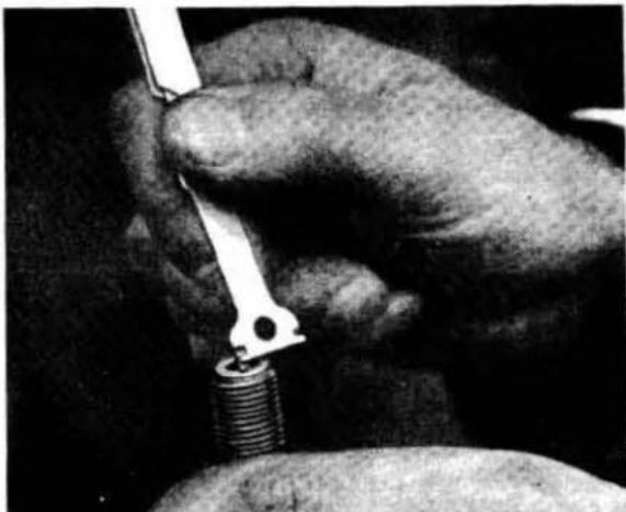
natural_image
Close-up of a hand using a tool to insert a screw into a mechanical component (no visible text or symbols)Fig.4.7. Setting the plug gap
15 The plug leads require no routine attention other than being kept clean and wiped over regularly. It is a good plan to remove them from the distributor, at the 10,000 mile servicing, by undoing the knurled terminal knobs or undoing the securing screws, as water can seep into these joints giving rise to a white corrosive deposit which, if present, must be carefully removed. 16 Finally, to get the best results from your engine, renew all plugs at 10,000 mile intervals. If the engine is in good condition the plugs will appear to be quite serviceable, and they probably are, but they have already given a useful life and in time some breakdown in insulation is inevitable even if it has not already occurred.
12 Ignition system - fault finding
By far the majority of breakdown and running faults are caused by faults in the ignition system, either in the low tension or in the high tension circuits. There are two main symptoms: either the engine will not start or fire or it is difficult to start and misfires. If it is a regular misfire i.e., one or more cylinders are not firing, the fault is almost certainly in the HT circuit. If misfiring is intermittent, the fault could be either in the HT or LT circuits. If the engine stops suddenly, or will not start at all, it is likely that the fault is in the LT circuit. Loss of power and overheating, apart from faulty carburation settings, are normally due to faults in the distributor or incorrect ignition timing.
13 Fault diagnosis - engine fails to start
1 If the engine fails to start and it was running normally when last used, first check that there is fuel in the tank. If the engine turns over normally on the starter and the battery is evidently well charged, then the fault may be in either the HT or LT circuit.
2 One of the commonest reasons for bad starting is wet or damp plugs, leads and distributor. Remove the distributor cap, if condensation is visible internally, dry the cap with a rag and wipe over the leads. Replace the cap.
3 If the engine still fails to start, check that current is reaching the plugs by disconnecting each plug lead in turn and holding the end of the lead about 3/16" away from the cylinder block. Switch on the ignition and spin the engine from the starter sole-noid (hold the lead with the rubber to avoid shock).
4 Sparking between the lead and the block should be fairly strong with a regular blue spark. If sparking, it is obvious that current is reaching the plugs so remove them, clean and regap. The engine should now start.
5 Spin the engine as before, when a rapid succession of blue sparks between the end of the lead and the block indicates that the coil is in order and that either the distributor cap is cracked, the carbon brush in the cap is stuck or worn, the rotor arm is faulty, or the contact breaker points are burnt, pitted or dirty. If the points are in bad shape, clean and reset them as described in Section 3.
6 If there are no sparks from the end of the lead, then check out the connections of the HT lead from the coil to the distributor. If that is in order, check the LT lead from the coil to the distributor and then go on to check the leads in the distributor especially between the condenser and the breaker terminal. Make sure that the earth lead is satisfactory.
7 Cases occur of the neck of the fibre body of the spring loaded contact breaker fracturing where it bears on the distributor shaft, check this.
8 If everything is visually in order and the engine still refuses to start, a physical check of the circuit using a 20 volt voltmeter or a test lamp will have to be made.
9 Turn the engine so that the contact breaker points are fully open, switch on the ignition. Check that current is reaching the starter solenoid switch from the battery. No reading indicates a fault in the cable to the cable to the switch, or in the connections at the switch or at the battery terminals. Alternatively

natural_image
Cross-sectional illustration of a mechanical component with threaded base and central bore (no text or symbols)Fig.4.8. Normal condition

natural_image
Close-up of a mechanical component with threaded base and central bore (no visible text or symbols)Fig. 4.9. Oil fouling or over-rich mixture

natural_image
Cross-sectional illustration of a mechanical component with internal cavity (no text or symbols)Fig. 4.10. Weak fuel mixture

natural_image
Illustration of a mechanical component inside a cylindrical housing (no text or symbols)Fig. 4.11. Burning; due to pre-ignition or plug of wrong heat value
the battery earth lead may not be properly earthed to the body.
10 If in order, check that current is reaching the fuse unit Al terminal. Connect the lamp between the fuse unit and earth. If there is no reading, this indicates a loose cable or faulty connection between the solenoid switch and the fuse unit.
11 If in order, check between the control box terminal A1 and earth. No reading indicates a fault in the control box. The control box will have to be replaced.
12 Next check that current is reaching the switch by connecting the lamp to the switch input terminal A and earth. A faulty cable or loose connection is indicated if there is no reading.
13 The next check is between the fuse unit A3 terminal and earth. Again, no reading shows that there is a faulty connection or a broken cable.
14 Now check between the ignition coil terminal SW and earth. A faulty connection or broken cable is indicated if there is no reading.
15 Connect the lamp between the ignition coil terminal CB and earth. If there is no reading, the ignition coil is faulty.
16 Now connect the lamp between the distributor low tension terminal on the side of the distributor and earth. If no reading check the connection and the cable especially at the point where it joins the tag.
17 The final check of the LT circuit is to connect the lamp across the contact breaker points. No reading means an unserviceable condenser and when this is replaced, the car should start.
14 Fault diagnosis - engine misfires
1 If the engine misfires regularly, run it at a fast idling speed, and short out each plug in turn using a screwdriver with a wooden or plastic insulated handle.
2 No difference in the speed of the engine will be noticed when the defective cylinder is short circuited but short circuiting of those cylinders working properly will accentuate the misfire.
3 Remove the plug lead from the suspect cylinder and hold, by the insulation, about 3/16" away from the cylinder block. If the sparking is regular and fairly strong, the fault must lie in the plug.
4 The plug may be loose, the insulation may be cracked, the points may be badly set or the plug very badly fouled. Either renew the plug, or clean it and reset the gap.
5 If there is no spark at the end of the lead or if it is weak and intermittent, check the condition of the lead from the plug to the distributor. Renew the lead if the insulation is cracked or perished. If the lead is in good order, disconnect it at the distributor and see if it is wet. If it is wet, dry it and the housing in the distributor, it will be a good plan to remove all the other leads and make sure that moisture is not present.
6 If there is no spark at the lead, examine the distributor cap carefully for tracking. This can be recognised as a thin black line running between two or more electrodes or between an electrode and some other part of the distributor. These lines are paths which conduct electricity across the cap and let it run to earth. If faulty in this respect, the cap must be replaced.
7 Apart from the ignition timing being incorrect, other causes of misfiring allied to the ignition circuit have already been dealt with in the previous Section.
Chapter 5 Clutch and actuating mechanism
Contents
| General description | ... | ... | ... | ... | ... | ... | 1 |
| Clutch system - bleeding | ... | ... | ... | ... | ... | ... | 2 |
| Clutch pedal - removal and replacement | ... | ... | ... | ... | ... | ... | 3 |
| Clutch pedal - free travel | ... | ... | ... | ... | ... | ... | 4 |
| Clutch - removal | ... | ... | ... | ... | ... | ... | 5 |
| Clutch - dismantling | ... | ... | ... | ... | ... | ... | 6 |
| Clutch - examination | ... | ... | ... | ... | ... | ... | 7 |
| Clutch - reassembly | ... | ... | ... | ... | ... | ... | 8 |
| Clutch - refitting | ... | ... | ... | ... | ... | ... | 9 |
| Clutch fork and release beairng - removal examination and refitting | ... | ... | ... | ... | ... | ... | 10 |
| Clutch master cylinder - general description | ... | ... | ... | ... | ... | ... | 11 |
| Clutch master cylinder - removal | ... | ... | ... | ... | ... | ... | 12 |
| Clutch master cylinder - dismantling | ... | ... | ... | ... | ... | ... | 13 |
| Clutch master cylinder - examination | ... | ... | ... | ... | ... | ... | 14 |
| Clutch master cylinder - reassembly | ... | ... | ... | ... | ... | ... | 15 |
| Clutch master cylinder - refitting | ... | ... | ... | ... | 16 |
| Clutch slave cylinder - general description | ... | ... | ... | ... | 17 |
| Clutch slave cylinder - removal | ... | ... | ... | ... | 18 |
| Clutch slave cylinder - dismantling | ... | ... | ... | ... | 19 |
| Clutch slave cylinder - examination | ... | ... | ... | ... | 20 |
| Clutch slave cylinder - reassembly | ... | ... | ... | ... | 21 |
| Clutch slave cylinder - refitting | ... | ... | ... | ... | 22 |
| Clutch slave cylinder hydrostatic type - operating rod adjustment | ... | ... | ... | ... | 23 |
| Removing and refitting a flexible hose | ... | ... | ... | ... | 24 |
| Fault diagnosis and remedy | ... | ... | ... | ... | 25 |
| Clutch squeal | ... | ... | ... | ... | 26 |
| Clutch slip | ... | ... | ... | ... | 27 |
| Clutch spin | ... | ... | ... | ... | 28 |
| Clutch judder | ... | ... | ... | ... | 29 |
Specifications
| 2.4 | 3.4 | 3.8 | |||||||
| Make ... | ... | ... | ... | ... | ... | ... | Borg and Beck | ||
| Model | ... | ... | ... | ... | ... | ... | 9A6 - G | 10A6 - G | 10A6 - G |
| Outside diameter | ... | ... | ... | ... | ... | ... | 9.13 - 9.16 in(231 - 232 mm) | 9.84 - 9.87 in(249 - 250 mm) | 9.84 - 9.87 in(249 - 250 mm) |
| Inside diameter | ... | ... | ... | ... | ... | ... | 6 - 12 in(153 - 154 mm) | 6.75 - 6.76 in(171 - 172 mm) | 6.75 - 6.76 in(171 - 172 mm) |
| Type ... | ... | ... | ... | ... | ... | ... | Single dry plate | ||
| Clutch release bearing | ... | ... | ... | ... | ... | Graphite | |||
| Operation ... | ... | ... | ... | ... | ... | ... | Hydraulic | ||
| Clutch thrust spring | |||||||||
| Number ... | ... | ... | ... | ... | ... | ... | 9 | 12 | 12 |
| Colour (early models) | ... | ... | ... | ... | ... | 6 cream/3 yellow/light green | cream | black | |
| (later models) | ... | ... | ... | ... | ... | Black | Yellow/ light green | Black | |
| Free length ... | ... | ... | ... | ... | ... | 2.68 in (68 mm) | 2.68 in (68 mm) | 2.68 in (68 mm) | |
| Driven plate - type | ... | ... | ... | ... | ... | Borglite | |||
| Driven plate damper springs - number | 6 | 6 | 6 | ||||||
| - colour | White/light green | Red/cream | Brown/cream | ||||||
240 and 340 models and also 3.4 litre Mk 2 and 3.8 litre commencing at engine numbers KJ.8237 and LE.2981 respectively:
| Borg and beck |
| Diaphragm spring |
| 8.5 in |
| 9.5 in |
1 General description
The clutch unit fitted to earlier produced cars is of the Borg and Beck single plate dry type which is hydraulically operated. An exploded view of the assembly is given in Fig.5.2. The clutch assembly comprises a steel cover which is bolted and dowelled to the rear face of the flywheel and contains the pressure plate, pressure plate springs, release levers and the driven plate.
The pressure plate, pressure springs and release levers are all attached to the clutch assembly cover. The driven plate is free to slide along, and is splined to, the first motion shaft of the gearbox and is held in position between the flywheel and the pressure plate by the pressure of the pressure plate springs. The driven plate is faced on both sides with friction material and has a spring cushioned hub to absorb transmission shocks.
The clutch is actuated hydraulically by a pendant clutch pedal which is connected to the combined clutch master cylinder and hydraulic fluid reservoir by a short pushrod. The master cylinder is mounted on the engine side of the bulkhead. A layout of the clutch hydraulic system is given at Fig.5.3. Depression of the clutch pedal moves the piston in the master cylinder forwards forcing hydraulic fluid through the pipe to the slave cylinder. The piston in the slave cylinder is now moved forward and actuates the clutch release arm by means of a short pushrod, the opposite end of the release arm is forked and carries the release bearing which is a graphite faced disc. As pressure on the clutch pedal continues, the release bearing bears hard on the release lever plate and pushes it forward, this movement rotates the release levers and they in turn pull back the pressure plate away from the driven plate and at the same time compress the thrust springs. The driven plate is now free of the flywheel and consequently there is no drive to the gearbox.
When the clutch pedal is released the thrust springs force the pressure plate into contact with the high friction linings of the driven plate to hold it firmly against the flywheel and so taking up the drive.
As the friction linings on the driven plate wear, the pressure plate automatically moves closer to the driven plate to compensate. This makes the inner ends of the release levers travel further towards the gearbox which decreases the release bearing clearance.
The diaphragm spring clutch fitted to later cars, which is illustrated in Fig.5.4, comprises a steel cover which is dowelled and bolted to the rear face of the flywheel and contains the diaphragm spring, the fulcrum rings and the pressure plate and the driven plate, which, as with the other type of clutch is splined to the first motion shaft of the gearbox.
The driven plate is held in position between the pressure plate and the flywheel by the pressure of the diaphragm spring. It has high friction material on both faces and has a spring cushioned hub to absorb transmission shocks.
The action on depressing the clutch pedal is similar to that which occurs with the other clutch except that in this instance the release bearing contacts the release plate which is a fixture on the diaphragm spring. Forward movement of the release plate causes a deflection of the diaphragm spring thus pulling the pressure plate away from the driven plate and freeing the clutch. When pressure on the clutch pedal is released, the diaphragm spring asserts itself to push the pressure plate hard against the driven plate to hold it in tight contact with the flywheel to transmit the drive to the gearbox.
2 Clutch system - bleeding
1 Bleeding the clutch hydraulic system (expelling air) is not a routine maintenance operation and should only be necessary when some portion of the hydraulic system has been disconnected or where, due to a leak, the level of fluid in the hydraulic reservoir has been allowed to drop too low. The presence of air in the system will result in poor clutch operation as the bubbles of air can be compressed.

natural_image
Technical cross-sectional diagram of a mechanical assembly (no visible text or labels)Fig.5.1. Sectional view of the 9A6-G/10A6-G clutch
- Thoroughly clean the top of the clutch master cylinder (the difference between the clutch and the brake master cylinders on early model cars is shown in Fig 5.5) and fill the cylinder with hydraulic fluid.
Note: Castrol Girling Universal Brake and Clutch Fluid is recommended. Where this is not available, only fluid guaranteed to conform to Specification SAE 70 R3 should be used as an alternative.
3 The bleed nipple for the system is located on the slave cylinder on the right hand side of the clutch housing. Thoroughly clean the exterior of the nipple.
4 Attach a length of rubber tube to the nipple and allow it to hang in a clean glass jar partly filled with hydraulic fluid.
5 Unscrew the nipple one complete turn.
6 Have an assistant in the car to depress the clutch pedal slowly to the full extent of its travel. Tighten the nipple whilst the clutch pedal is held depressed.
7 Release pressure on the clutch pedal and repeat operations 5 and 6 until the fluid issuing from the tube is entirely free of air. Take care to replenish the reservoir frequently during these operations because if the fluid level is allowed to drop more than halfway, air will enter the system.
8 When you are satisfied that the system is clear of air, top up the master cylinder reservoir to the bottom of the filler neck.
9 Do not use the fluid which has been bled through the system as this will be aerated. Always use fresh fluid straight from the container.

FIG.52. EXPLODED VIEW OF THE 9A6-G/10A6-G CLUTCH
1 Cover
2 Thrust spring
3 Pressure plate
4 Release lever
5 Release lever plate
6 Release lever retainer
7 Release lever strut
B Release lever eyebolt
9 Eyebolt pin
10 Adjustment nut
11 Anti-rattle spring
12 Release bearing and cup assembly
13 Release bearing
retainer
14 Driven plate assembly
15 Securing bolt
16 Spring washer
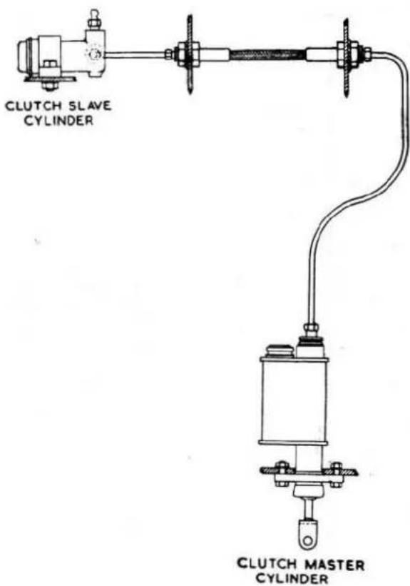
Fig.5.3. The clutch hydraulic system

FIG.5.4. EXPLODED VIEW OF THE DIAPHRAGM SPRING CLUTCH
1 Driven plate
2 Pressure plate
3 Rivet
4 Centre sleeve
5 Belleville washer
6 Fulcrum ring
7 Diaphragm spring
8 Cover pressing
9 Release plate
10 Retainer
11 Tab washer
12 Setscrew
13 Retainer
14 Release bearing
3 Clutch pedal - removal and replacement
1 The clutch and brake pedals are an assembly on a common mounting block which also forms a base for the clutch and brake master cylinders.
2 Disconnect the pipe to the clutch master cylinder by unscrewing the union nut. Tie a piece of rag around the pipe and union nut and block the orifice in the master cylinder to prevent the ingress of dirt.
3 Disconnect the two pipes to the brake master cylinder by undoing the union nuts. Protect the pipes and the orifices in the same manner as the clutch hydraulics.
4 Push the driving seat back to its full extent on the runners.
5 Remove the carpet and the sound proofing around the pedal assembly.
6 Remove the foot plates from the clutch and brake pedals by undoing the self locking nut at the base of each pedal.
7 Remove the seven nuts and shakeproof washers securing the mounting block to the bulkhead.
8 Lift out the pedal assembly from the engine compartment complete with the clutch and brake master cylinders. Keep the assembly upright until you have drained the contents of the dutch master cylinder tank into a clean container. Note the gasket fitted between the mounting block and the bulkhead.
9 Remove the split pin securing the clevis pin connecting the clutch and brake pedals to their respective master cylinders; take off the flat washer and push out each clevis pin.
10 Remove the nuts and shakeproof washers securing the clutch and brake master cylinders respectively, to the mounting block. Remove the cylinders and store them where they will not be damaged or collect dirt.
11 Remove the nut securing the pinch bolt between the two pedals, remove the pinch bolt.
12 Note the way in which each pedal return spring is fitted.
13 Knock out the pedal axis pin. Note that it will only come out in one direction as it is fouled by one of the mounting studs in the other direction.
14 Note the fibre washers between the side of each pedal and the mounting block.
15 Replacement is a reversal of the removal procedure. The clutch and brake pedals axes and springs should be treated with grease.
16 Finally, bleed the clutch hydraulic system as described in Section 2 and bleed the brake system as described in Chapter 9.

natural_image
Simple line drawing of a mechanical setup with stacked blocks and a cylindrical component (no text or symbols)BRAKE

natural_image
Simple line drawing of a laboratory setup with a beaker, tube, and glass (no text or labels)CLUTCH
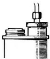
natural_image
Simple line drawing of a laboratory setup with a bench, test tube, and stacked books (no text or labels)BRAKE
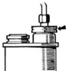
natural_image
Simple line drawing of a laboratory apparatus with no visible text or symbolsCLUTCH
Fig.5.5. Difference between clutch and brake master cylinders (early model cars)
4 Clutch pedal - free travel
1 Commencing at the engine numbers given next, a hydrostatic clutch operating slave cylinder is fitted and normal clutch wear is automatically compensated for so no adjustment at the pedal is necessary. The later type slave cylinder is not fitted with the spring.
2.4 litre Mk. 2 BJ.5110
3.4 litre Mk. 2 KJ.7659
3.8 litre Mk. 2 Le.2533
2 There should be 34 " (19 mm) free travel or unloaded movement at the clutch pedal before feeling the resistance of the springs. This is best felt by moving the pedal by hand.
3 Refer to Fig.5.6.
4 Adjustment is effected by slackening the locknut which can be seen against the head of the pushrod. Screwing the rod into the head will increase the free pedal travel whilst screwing it out will decrease the free travel.
5 Screw up the locknut when the adjustment is correct.
6 This adjustment is most important for:
a) Insufficient free travel may cause a partly slipping clutch leading to burning out if not corrected. Over-travel of the pedal will also result and will cause undue internal strain and excessive bearing wear.
b) Too much free pedal movement results in inadequate release movement of the bearing and may produce a dragging clutch condition making clean gear changes impossible.

natural_image
Technical line drawing of a mechanical assembly with no visible text or symbolsFig.5.6. Clutch pedal adjustment
5 Clutch - removal
1 Remove the engine and the gearbox from the car and separate the gearbox from the engine in the manner described in Chapter 1.
2 Look for the balance marks stamped on the clutch housing and eel as depicted in Fig.5.7. If there are no marks make your own with a centre punch so that the clutch assembly can be replaced on the fylwheel in its original position.
3 Slacken the clutch mounting screws a turn at a time by diagonal selection until the thrust spring pressure is released. Remove the setscrews.
4 Withdraw the clutch assembly from the dowels on the flywheel at the same time taking care that the driven plate, which will not now be supported, does not fall away and get damaged.
5 Do not handle the driven plate with oily hands. If it is to be re-used, place it where it will not be dirtied or damaged.
6 Clutch - dismantling
1 The following paragraphs 2 - 8 inclusive, refer to the 9A6G and 10A6G type clutch using thrust springs for the operation of the pressure plate.
2 Before dismantling, mark all he major components for reassembly in their original positions.
3 It is now necessary to evenly compress the thrust springs and to take their weight whilst removing the adjusting nuts from the eyebolts. One way of doing this without the use of special equipment is to bolt the clutch to a flywheel in order to put pressure on the pressure plate but a press is really the answer. Place the clutch on the bed of the press with wood blocks under the pressure plate in such a manner that the cover can move downwards when pressure is applied, this set-up is shown in Fig.5.8.
4 Having compressed the clutch, unscrew the adjusting nuts
(Fig.5.9). These are locked by staking and considerable torque may be necessary in order to break the lock.
5 Slowly release the clamping pressure when all the nuts are removed.
6 Lift the cover and the thrust springs off the pressure plate and remove the release lever mechanism.
7 Note the positions of the various coloured thrust springs.
8 Fig.5.10 shows how the strut is disengaged from the lever after which the threaded end of the eyebolt and the inner end of the lever are held as close together as possible so that the shank of the eyebolt clears the hole in the pressure plate.
9 The following paragraphs refer to the diaphragm spring type of clutch.
10 The Borg and Beck diaphragm spring type of clutch is serviced in this country by fitting an exchange unit and as these are readily available from your Jaguar agency it is strongly recommended that you do not attempt to dismantle the assembly.
11 However, individual parts can be obtained for the repair of the clutch and the following instructions for dismantling are given for the benefit of Overseas customers in cases where complete exchange units may not be readily available.
12 It is essential to rigidly observe the following instructions and in particular, attention is drawn to the necessary special tools required.
13 Refer to Fig.5.4.
14 The centrally mounted release plate is held in position by a centre sleeve which passes through the diaphragm spring and the belleville washer into the release plate. To free the plate, collapse he centre sleeve with a hammer and chisel as shown in Fig.5.11. Support the release plate in the locating boss of the special tool, shown at Fig.5.20, which should be held firmly in a vice.
15 Knock back the locking tabs and remove the three setscrews securing the pressure plate to the straps rivetted to the cover pressing. DO NOT detach the straps from the cover pressing.
16 Using a spot face cutter, machine the shank of the rivets securing the diaphragm spring and the fulcrum rings to separate those items. Drive out the rivets with a standard pin punch. It is essential that the thickness of the cover is not reduced in excess of 0.005" (0.127 mm) at any point (see Fig.5.12).
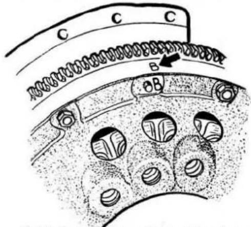
Fig.5.7. Balance marks on clutch and flywheel
7 Clutch - examination
We advise that you fit a new driven plate. But if you decide against this:
1 Examine the friction facings. They will probably be highly polished, through which the grain of the material can be clearly seen, and mid-brown in colour. The facings are satisfactory if in this condition but if there are dark, highly glazed, patches which hide the grain or if there is a resinous deposit on the facings or if they have a black soaked appearance the indication is that they
are contaminated with oil and the driven plate assembly should be renewed.
2 Examine the rivets of the driven plate. They should be well below the surface of the friction material and should be secure. Renew the driven plate if the facings are worn or if any rivets are loose.
3 Check the driven plate springs for fracture and security. Check the condition of the splines in the centre hub, excessive wear, which results from faulty alignment will mean renewing the plate.
4 Examine the thrust springs and check their length. Do not
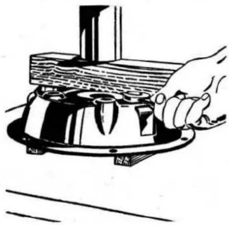
natural_image
Illustration of a hand operating a mechanical component with a base plate (no text or symbols visible)Fig.5.8. Compressing the thrust springs
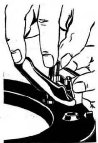
natural_image
Illustration of hands operating a mechanical component (no text or symbols visible)Fig.5.10. Disengaging the strut from the lever
immediately discard any which are under length but check them against one which is of the correct length by placing end to end in a vice with a metal plate interposed between them, screw up the vice to put pressure on the springs but not to compress them fully. Measure their lengths and if the short spring is now under-size compared to the other, discard it.
5 The face of the pressure plate should not be ridged or pitted and this also applies to the face of the flywheel in the bearing area of the driven plate.
6 Check that the flange of the cover is not distorted.

natural_image
Illustration of hands using a wrench to adjust or install a mechanical component (no text or symbols visible)Fig.5.9. Removing the adjusting nuts
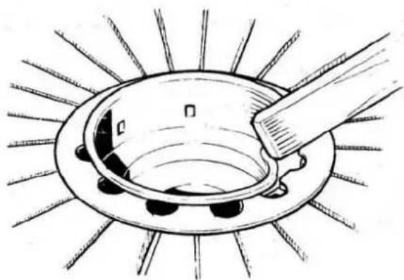
natural_image
Diagram of a mechanical component with radiating lines and a brush, no text or symbols presentFig.5.11. Collapsing the centre sleeve

Fig.5.12. Showing maximum permissible depth for removal of rivets
8 Clutch - reassembly
1 It is essential that all major components are returned to their original positions if balance of the assembly is to be maintained.
2 The instructions contained in paragraphs 3-19 inclusive refer to the 9A6G and 10A6G type clutch utilising thrust springs.
3 Fit a pin into an eyebolt and locate the parts within a release lever.
4 Hold the threaded end of the eyebolt and the inner end of the lever as close together as possible, and, with the other hand, engage the strut within the slots in a lug on the pressure plate, push outwards on the other end of the strut towards the rim of the plate.
5 Offer up the lever assembly, first engaging the eyebolt shank within the hole in the plate. Now locate the strut within the groove in the lever.
6 Fit the remaining release levers in the same manner and lightly lubricate all bearing surfaces.
7 The cover now has to be assembled to the pressure plate using some method, as during dismantling, to compress the thrust springs. Assuming that a press is being used, support the pressure plate on two blocks of wood on the bed of the press.
8 Assemble the thrust springs on the bosses of the pressure plate, if the springs are not of the same colour for this particular clutch they must be arranged in a symmetrical manner.
9 Assemble the anti-rattle springs to the cover.
10 Rest the cover on the thrust springs so that the pressure plate lugs are aligned with the slots in the cover.
11 Place a wooden block across the top face of the cover and apply pressure with the press to compress the assembly.
12 Screw the adjusting nuts into an approximate correct position.
13 The release levers must now be set to their correct height and the following procedure assumes that a special setting fixture or gauge plate is not available.
14 Mount the clutch on the flywheel with the driven plate in its normal position or, alternatively, clamp the assembly to any truly flat surface having clearance for the boss of the driven plate.
15 Refer to Fig. 5.13.
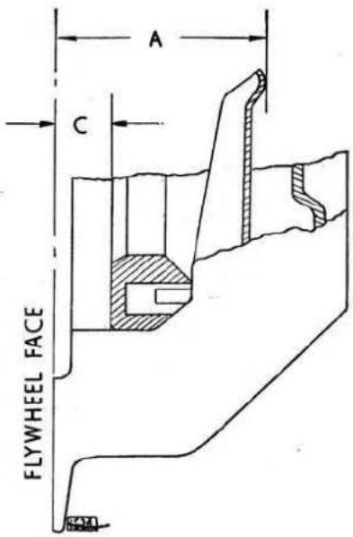
Fig.5.13. Setting the release levers
17 Having set the levers, slacken the clamping pressure and turn the driven plate through 90°, reclamp the cover and check the levers again as an insurance against any lack of truth in the driven plate.
18 When satisfied with the setting of the release levers, lock all adjusting nuts by staking.
20 The following instructions apply to the diaphragm spring type clutch.
21 First check the cover pressing for distortion by bolting the cover firmly to a truly flat surface and then measuring the distance from the cover flange to the machined land inside the pressing. This, as indicated in Fig. 5.14, should not be more than 0.007" (0.2 mm). If this dimension is exceeded the cover must be replaced.
22 Make up a tool to the dimensions given in Fig.5.15. Except for the spring all parts can be made out of mild steel.
16 Adjust on the adjusting nuts until the tips of the release levers, dimension "A", are 1.895" from the flywheel face in the case of the 9 inch clutch fitted to 2.4 litre engines and are 1.955" for the 10" clutch of the 3.4 and 3.8 litre models. Dimension "C" is 0.33" for both sizes of clutch.
19 Fit the release lever retainers and the release lever plate.
23 Place the fulcrum ring inside the cover pressing so that the location notches in the fulcrum ring engage a depression between two of the larger diameter holes in the cover pressing. See Fig.5.16.
24 Place the diaphragm spring on the fulcrum ring inside the cover and align the long slots in the spring with the small holes in the cover pressing.
25 Locate the other fulcrum ring on the diaphragm spring so that the location notches are diametrically opposed to the location notches in the first ring.
26 Fit new rivets and ensure that the shouldered portion of each seats on the machined land inside the cover.
27 Place the base plate of the tool on to the rivet heads and invert the clutch and base plate (Fig.5.17).
28 Fit the collar of the tool over the large bolt and fit the large bolt complete with spring, spider and collar into the tapped hole in the base. Position the three setscrews on the spider of the tool so that they contact the cover pressing.
29 Tighten down the centre bolt, as depicted in Fig.5.18, until the diaphragm spring is flat and the cover pressing is held firmly by the setscrews.
30 Peen over the rivets with a hand punch (Fig.5.19).
31 Before assembling the pressure plate examine it for wear or damage. If damaged or excessively scored it should be replaced but if this is not possible it is permissible to rectify it by grinding but this must be expertly done as incorrect grinding may affect operation of the clutch. The pressure plate must not be worked to a thickness of less than 1.070" (27.178 mm).
32 Position the pressure plate inside the cover assembly so that the lugs on the plate engage the slots in the cover pressing.
33 Insert the three setscrews through the straps which are rivetted to the cover pressing, tighten down and lock with the tab washers.
34 The pressure plate must now be fitted and for this a special tool is required. The tool number is SSC805 and it can be obtained from Automotive Products Ltd, Service and Spares Division, Banbury, England. The tool is shown in Fig.5.20 for information.
35 Grip the base plate of the tool in a vice and place the locating boss into the counterbore.
36 Place the release plate, face down, into the counterbore of the locating boss.
37 Apply a little high melting point grease to the tips of the diaphragm spring fingers and position the clutch, with the pressure plate friction face upwards, on to the release plate. Ensure that the diaphragm spring fingers locate between the small raised pips on the release plate.
38 Place the belleville washer, concave surface towards the spring, on to the centre of the diaphragm spring and then push the centre sleeve through the spring into the release plate.
39 Drop the special washer of the tool into the sleeve and insert
the staking guide into the centre of the assembly. Fit the knurled nut to the thread on the staking guide and tighten down until the whole assembly is solid.
40 Using the special punch, inserted in the slots in the staking guide, stake the centre sleeve in six places into the groove in the release plate.(Fig.5.21).
Fig. 5.14. Check for distortion of cover pressing. Maximum variation of dimension 'A' must not exceed 0.007 inch

FIG.5.15. SPECIAL TOOL FOR COMPRESSING DIAPHRAGM SPRING
| Ref. | Qty. | Description |
| A | 6 | 14'' flat washer |
| B | 3 | 14'' nut |
| C | 3 | 114'' diameter setscrew |
| D | 1 | Spring (minimum load of 100 lbs.fitted length) |
9 Clutch - refitting
| Ref. | Qty. | Description |
| E | 1 | Washer 1⁄2" I.D. x 11⁄2" O.D. x 3⁄4" thick |
| F | 1 | Tube 1⁄2" I.D. x 31⁄4" long |
| G | 2 | Washer 7/8" I.D. x 11⁄2" O.D. x 1/8" thick |
| H | 1 | Bolt 1⁄2" Whit. x 6" long |
constant pinion shaft splines will pass through the splines in the centre of the driven plate hub.
6 If you have the facilities, turn up a piece of bar to the inside diameter of the splines in the driven plate with a reduced diameter at one end to just enter the constant pinion shaft bearing at the rear of the crankshaft.
7 Insert the bar through the hole in the centre of the clutch and move it until the small diameter enters the constant pinion shaft bearing in the crankshaft. The driven plate is now correctly aligned. Leave the bar in position.
8 An old constant pinion shaft (Fig.5.22) can be used instead of the bar but failing all else, centralisation of the driven plate can be carried out by using a long screwdriver inserted from the rear of the clutch. Moving the screwdriver sideways or up and down will move the plate in whatever direction is necessary to achieve centralisation. Correct positioning of the driven plate can
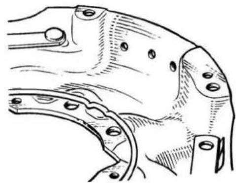
natural_image
Technical line drawing of a mechanical component with bolt holes and flanges (no text or symbols)Fig.5.16. Assembly of fulcrum ring to cover pressing

natural_image
Technical line drawing of a mechanical clutch assembly (no text or symbols)Fig.5.17. Clutch and base plate of tool inverted

natural_image
Technical illustration of a mechanical clamp or spring assembly with no visible text or symbolsFig.5.18. Positioning the tool for rivetting

FIG.5.20. SPECIAL TOOL SSC 805

natural_image
Illustration of a hand using a tool to adjust or install a mechanical component (no text or symbols visible)Fig.5.19. Rivet securely with a hand punch
1 Staking guide
2 Washer
3 Locating boss
4 Base plate
5 Knurled nut
6 Punch

natural_image
Line drawing of a plate with cutouts and a knife, no text or symbols presentFig.5.21. Staking the centre sleeve to the release plate
be judged by a viewing its position in relation to the hole at the rear of the clutch.
9 Tighten the setscrews a turn at a time by diagonal selection whilst the bar is still holding the driven plate in position. Tighten down fully and remove the bar. If using a screwdriver or similar tool for centralisation, re-check that the driven plate is still central as there is a tendency for it to move during the tightening operation.
10 Clutch fork and release bearing - removal, examination and refitting
1 With the gearbox and engine separated to provide access to the clutch, attention can be given to the release bearing and fork, and lever located in the gearbox bellhousing.
2 To remove the clutch release bearing, ease back the two spring clips located at the ends of the release bearing carrier and lift away the release bearing (photos).
3 Slacken the locknut and using an Allen key, remove the lever shaft retaining screw (photo).
4 Pressout the release lever shaft (photo).
5 Remove the release lever (photo).
6. If the graphite release bearing ring is badly worn it should be replaced by a complete bearing assembly. Our advice is that a new release bearing is fitted irrespective of the condition of the one removed as a lot of clutch troubles start with this component.
7 Check the fork ends and the lever shaft for wear, renew as necessary.
8 Reassembling the clutch fork and lever assembly and refitting the clutch release bearing is the reverse of the dismantling procedure.

natural_image
Technical line drawing of a mechanical gear assembly (no text or symbols)Fig.522. Controlling the driven plate

natural_image
Close-up of a mechanical component with no visible text or symbols10.2a. Removing spring clips
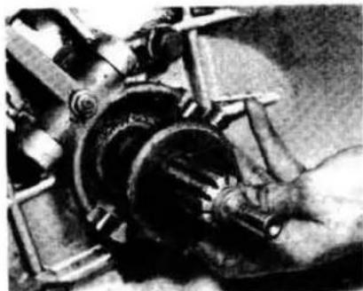
natural_image
Close-up of mechanical components with no visible text or symbols10.2b. Lift away release bearing

natural_image
Black-and-white photo of a mechanical assembly with gears and levers (no visible text or symbols)10.3a. Slacken retaining screw locknut
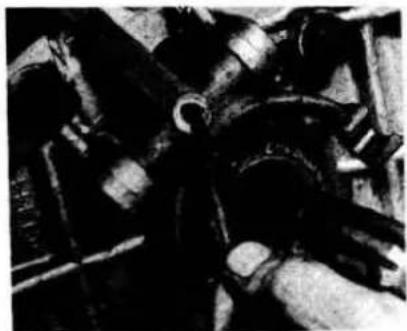
natural_image
Close-up of mechanical components with no visible text or symbols10.3b. Lever shaft retaining screw
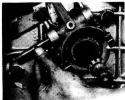
natural_image
Close-up of mechanical components with no visible text or symbols10.4. Removing the release lever shaft

natural_image
Close-up of mechanical components with no visible text or symbols10.5. Removing the release lever
11 Clutch master cylinder - general description
The master cylinder consists of a combined tank and barrel assembly as depicted in Fig.5.23. The tank surrounds the barrel assembly and its purpose is to provide a reserve of fluid to make good, temporarily, any loss in the system as may arise. It also provides a reserve of fluid to fill the space created by the displacement which occurs when the clutch pedal is depressed to operate the hydraulic components. The tank is fitted with a filler cap which incorporates a baffle and which screws down against a seal.
A fixing flange is mounted at one end of the barrel assembly and contained within the assembly is a piston which has a rubber main cup spring loaded against one end. Between the cup and the piston is a thin washer which prevents the cup being drawn into the small feed holes drilled around the piston head. At the other end of the piston is a rubber secondary cup which is formed with a depression to take the spherical end of a push rod fitted with a piston stop and retained by a circlip. The push rod, which is connected to the clutch pedal, passes through a rubber boot which fits over the end of the barrel and prevents the ingress of dirt and moisture. At the opposite end of the push rod is an end plug which screws down against a gasket and forms the outlet connection.
When the clutch pedal is depressed, the push rod forces the piston along the bore of the barrel carrying with it the main cup, the fluid displaced by the main cup passes to the slave cylinder. When the clutch pedal is released, the return spring forces the piston back against its stop faster than the fluid is able to return from the slave cylinder; this creates a depression in the master cylinder and the edge of the main cup is drawn away from the head of the piston to uncover the holes. This allows fluid to flow from the tank through the feed holes to make up the temporary deficiency. Fluid, returning from the slave cylinder, under pressure of the clutch operating fork tries to re-enter the master cylinder but is unable to do so until the piston is fully back against its stop when the main cup uncovers a small by-pass hole in the barrel and allows excess fluid to escape to the tank. The by-pass hole also compensates for contraction and expansion of the fluid as the result of temperature changes; if the port becomes blocked, the excess fluid will be unable to escape and clutch slip will result.
12 Clutch master cylinder - removal
1 Disconnect the outlet pipe from the end of the master cylinder. Tie a piece of rag around the pipe and plug the inlet to the cylinder to prevent ingress of dirt.
2 Detach the fork end from the clutch pedal.
3 Unscrew the fixing nuts and detach the master cylinder.
4 Remove the filler cap and drain the fluid into a clean container.
5 Replace the cap to prevent the ingress of dirt.
13 Clutch master cylinder - dismantling
1 Thoroughly clean the exterior of the master cylinder.
2 Prepare a clean working space on the bench top and cover it with a length of clean cloth or strong paper. Clean your hands and maintain absolute cleanliness all the time you are working on the hydraulic components.
3 Detach the rubber boot from the end of the master cylinder and slide it along the push rod.
4 Depress the push rod to relieve the spring load on the circlip and remove the circlip.
5 Withdraw the push rod followed by the piston, piston washer, main cup and spring, these can be removed by vigorous shaking.
6 The secondary cup is removed by stretching it over the end of the piston. Note which way round it is fitted.
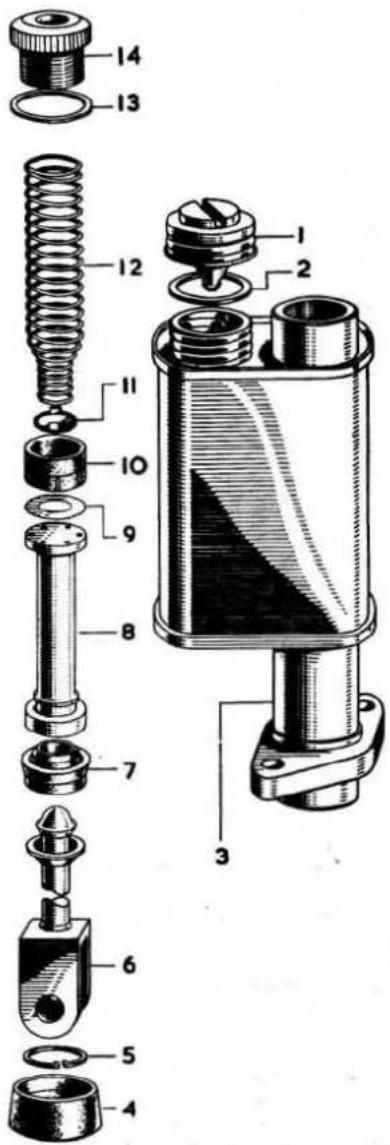
FIG.5.23. EXPLODED VIEW OF THE CLUTCH MASTER CYLINDER
1 Filler cap 8 Piston
2 Seal 9 Washer
3 Barrel assembly 10 Rubber main cup
4 Rubber boot 11 Spring retainer
5 Circlip 12 Spring
6 Pushrod 13 Gasket
7 Rubber secondary cup 14 End plug
7 There is normally no need to remove the end plug from the barrel.
14 Clutch master cylinder - examination
1 Thoroughly clean all parts in brake fluid and dry off with a non-fluffy cloth. Under no circumstances must oil, grease, paraffin etc; be allowed to come into contact with the rubber parts if you intend to use them again.
2 It is strongly recommended that all rubber seals are replaced as a matter of course but if you intend to use them again, inspect each item carefully for signs of distortion, swelling, splitting or hardening any of which faults will necessitate replacement.
3 Inspect the bore and piston for scoring evidence of which will mean replacement.
4 Make sure that the holes in the head of the piston and the by-pass port in the cylinder are clear by poking gently with a piece of thin wire.
15 Clutch master cylinder - reassembly
1 As parts are refitted to the cylinder bore make sure that they are thoroughly wetted with clean hydraulic fluid.
2 If you have removed the end plug, replace it together with a new gasket.
3 Fit the spring retainer on the small end of the spring (if it has been removed) and secure it by bending over the ears onto the spring.
4 Insert the spring, large end first, into the barrel and then insert the main cup with the lip leading, taking care not to bend back or buckle the lip.
5 Insert the piston washer with the curved end towards the main cup.
6 Stretch the secondary cup onto the piston with the small end towards the drilled head of the piston. Make sure that the groove in the cup engages the ridge on the piston and gently work round the cup, with the fingers, to make sure that it is bedded properly. Use fingers only to stretch the cup on to the piston.
7 Insert the piston into the barrel with the drilled head leading.
8 Stretch the rubber boot onto the push rod so that the open end of the boot is towards the spherical end of the push rod.
9 Offer the push rod to the barrel, push it inwards and secure in position by fitting the circlip. Ensure that the circlip is fitted correctly in its groove.
10 Stretch the rubber boot onto the end of the barrel and make sure it is in its correct position.
16 Clutch master cylinder - refitting
1 Place the master cylinder over the mounting studs on the body of the car, fit each stud with a shakeproof washer and secure the master cylinder with its nuts.
2 Attach the clutch pedal to the fork end of the master cylinder push rod by means of the clevis pin. Fit a plain washer to the end of the clevis pin and insert and open the legs of a split pin to secure.
3 Attach the outlet pipe to the end plug taking care not to cross thread the union nut.
4 Fill the master cylinder tank with clean hydraulic fluid and bleed the system in the manner described in Section 2.
5 Check for leaks by depressing the clutch pedal once or twice and examining all hydraulic connections.
17 Clutch slave cylinder - general description
The clutch slave cylinder is the link between the master cylinder and the release bearing operating lever. It is essentially a casting with an integral mounting flange and two screwed connection points, the connection for the pipe from the master cylinder is that parallel to the mounting flange whilst the other connection is for the bleeder screw.
The clutch slave cylinder is illustrated in Fig.5.24. The body is bored and coned to fine limits and accommodates a piston against the inner face of which is a rubber cup loaded by a cup filler and spring. The travel of the piston is limited by a circlip which fits into a groove at the rear of the bore. The end of the bore is protected against the intrusion of dirt by a rubber boot through which a push rod, connected to the release bearing operating lever, passes.
Hydraulic pressure from the master cylinder moves the

FIG.5.24. EXPLODED VIEW OF THE CLUTCH SLAVE CYLINDER
1 Spring 5 Piston
2 Cup filler 6 Circlip
3 Cup
4 Body
rubber cup, and piston rearwards; the piston is bearing on the pushrod and this in turn, is moved rearwards and pivots the release bearing operating lever to which it is connected. When the clutch pedal is released, spring pressure on the operating lever moves the components back to the "at rest" position.
18 Clutch slave cylinder - removal
1 Disconnect the pipe from the master cylinder. Cover the end of the pipe with a piece of rag and plug the connection in the body of the cylinder to prevent the ingress of dirt.
2 Unhook the return spring from its clip on those cars not fitted with a hydrostatic slave cylinder.
3 Remove the securing nuts from the studs. Remove the shake-proof washers.
4 Pull the slave cylinder away from the car and forwards leaving the push rod attached to the car.
19 Clutch slave cylinder - dismantling
1 Thoroughly clean the exterior of the cylinder.
2. Prepare a clean space on the bench and cover it with a length of clean cloth or strong paper. Clean your hands.
3 Remove the rubber from the end of the body.
4 Remove the circlip from the end of the bore.
5 Apply a low air pressure from, say, a foot pump to the open connection to expel the piston and the other parts. It is advisable to hold a piece of rag over the end of the bore to catch the parts as they are pushed out.
6 Remove the bleed screw.
20 Clutch slave cylinder - examination
1 Thoroughly clean all parts and the interior of the bore with clean hydraulic fluid. Do not allow oil, grease, paraffin etc: to come into contact with the rubber parts if you intend to use them again.
2 We strongly recommend that the rubber parts are renewed but if you intend to use them again examine them carefully for signs of distortion, swelling, splitting or hardening either of which faults will necessitate replacement.
3 Examine the bore and piston for signs of deep scoring which, if present will mean replacement.
4 Examine the body in the area of the bleeder screw connection for cracks as may result from overtightening of the bleeder screw.
21 Clutch slave cylinder - reassembly
1 Smear all parts and the bore of the body with hydraulic fluid.
2 Fit the spring in the cup filler and then insert these, with the spring leading, into the bore of the body.
3 Insert the cup with the lip leading into the bore taking care not to turn back or buckle the lip.
4 Fit the piston with the flat face leading.
5 Fit the circlip into its groove in the rear of the bore and make sure that it is seated correctly in the groove.
6 Fit the rubber boot to the rear of the body.
7 Refit the bleeder screw.
22 Clutch slave cylinder - refitting
1 Offer up the slave cylinder to the vehicle and enter the push rod into the bore through the rubber boot.
2 Hook the return spring onto its clip on those cars so fitted.
3 Fit the body of the cylinder over the studs. Fit the shake-proof washers and nuts and tighten down.
4 Reconnect the pipe from the master cylinder taking care not to crossthread the nut.
5 Bleed the system in he manner described in Section 2.
6 Have an assistant to operate the clutch pedal two or three times and check for leaks.
7 Refer to Section 23 and adjust the operating rod if appropriate.
23 Clutch slave cylinder hydrostatic type - operating rod adjustment
The hydrostatic slave cylinder as fitted to later model cars can be identified by the absence of the return spring as fitted to the previous slave cylinder body. When refitting the hydrostatic slave cylinder it is important that the operating rod adjustment dimension as shown in Fig.5.25, is obtained. Proceed as follows:
1 Extract the clevis pin securing the rod to the clutch lever.
2 Hold the head of the rod and release the locknut.
3 Push the clutch operating lever away from the slave cylinder until resistance is felt and retain it in this position.
4 Push the rod to the limit of its travel into the bore of the cylinder and adjust the fork end until a dimension of 0.75" (19 mm) between the centre of the fork end and the centre of the clutch operating lever is obtained. Tighten the locknut.
5 Release the operating rod and connect the fork end to the
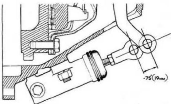
Fig.5.25. Setting dimension - Hydrostatic slave cylinder
lever by means of the clevis pin. Fit a plain washer and split pin to the clevis pin.
24 Removing and refitting a flexible hose
1 Carefully remove all dirt from each union of the flexible hose.
2 Have a clean jar handy to catch any fluid which may drain when the pipe is disconnected.
3 Unscrew the tube nut from the hose union and allow hose to drain.
4 Unscrew the locknut and withdraw the hose from the bracket.
5 Undo the hose at the other connection to the rigid pipe.
6 When refitting a hose it is essential to check that it is not twisted or kinked.
7 Pass the hose union through the bracket. Hold the union with a spanner to prevent the hose from twisting. Fit a shakeproof washer and tighten down on the locknut.
8 Connect the pipe by screwing on the tube nut.
9 Repeat the above for the other end of the pipe.
25 Fault diagnosis and remedy
There are four main faults to which the clutch and the release mechanism are prone. They may occur by themselves or in conjunction with each other. They are clutch squeal, slip, spin and judder.
26 Clutch squeal
1 If, on taking up the drive or when changing gear, the clutch squeals, it is an indication of a badly worn clutch release bearing.
2 As well as regular wear due to normal use, wear of the clutch release bearing is accentuated if the clutch is ridden or held down for long periods in gear with the engine running. To minimise wear of this nature the car should always be taken out of gear at traffic lights or at similar hold-ups.
3 The clutch release bearing is not an expensive item but it is difficult to get as its replacement requires the removal of the engine and gearbox assembly and work as detailed in Section 10.
27 Clutch slip
1 Clutch slip is a self evident condition which occurs when the clutch driven plate is badly worn or oil or grease have got onto the flywheel or pressure plate faces. It may also be that the pressure plate is faulty.
2 The reason for clutch slip is that due to one or more of the faults above, there is either insufficient pressure from the pressure plate, or insufficient friction in the driven plate to ensure a solid drive.
3 If small amounts of oil get onto the clutch, they will be burnt off under the heat of clutch engagement and in the process will gradually darken the linings. Excessive oil on the clutch will burn off leaving a carbon deposit which can cause quite bad slip or fierceness, spin and judder.
4 If clutch slip is suspected and confirmation of this condition is required, there are several tests which can be made.
5 With the engine in second or third gear and pulling lightly, sudden depression of the accelerator pedal may cause the engine to increase speed without any noticeable increase in road speed. Easing off on the accelerator will cause a drop in engine speed but not in road speed.
6 In extreme cases of clutch slip the engine will race under normal accelerating conditions.
7 If slip is due to oil or grease on the linings a temporary cure can sometimes be effected by squirting carbon tetrachloride into the clutch. The permanent cure is, of course, to renew the clutch driven plate and to investigate and to cure the cause of the oil leak.
28 Clutch spin
1 This is a condition which occurs when there is a leak in the clutch hydraulic system, when there is an obstruction in the clutch either in the first motion shaft or in the operating lever itself, or when oil may have left a resinous deposit on the driven plate causing it to stick to either the pressure plate or the
flywheel.
2 The reason for clutch spin is that due to one or more of the above faults, the clutch pressure plate is not completely freeing even with the clutch pedal completely depressed.
3 The symptoms of clutch spin are difficulty in engaging a gear from rest, difficulty in changing gear, and a very sudden take up of the drive at the fully depressed end of the clutch pedal travel as the clutch is released.
4 Check the clutch master cylinder, the slave cylinder and hydraulic connections for leaks. Fluid in one of the rubber boots is a sure sign of a leaking piston seal.
5 If these points are checked and are found to be in order then the fault lies internally in the clutch which will have to be removed for examination.
29 Clutch judder
1 Clutch judder is a self evident condition which occurs when the gearbox or engine mountings are loose or are too flexible, or when there is oil on the face of the driven plate or when the pressure plate has been incorrectly adjusted.
2 The reason for clutch judder is that due to one of the above faults, the pressure plate is not freeing smoothly from the driven plate and is snatching.
3 Clutch judder is usually most noticeable when the clutch pedal is released in first or in reverse gear and the whole car judders as it moves backwards or forwards.
Chapter 6 Gearbox, overdrive and automatic transmission
Contents
| Number of forward speeds | ... | ... | ... | ... | ... | ... | Four |
| Synchronesh | |||||||
| Mk 1 and early Mk 2 models | ... | ... | ... | ... | ... | ... | Second, third and top gears |
| Later Mk 2, 240 and 340 models | ... | ... | ... | ... | ... | ... | All four forward gears |
| Gearbox ratios | |||||||
| Prefix GB or GBN | |||||||
| Suffix - none or 'O' ... | ... | ... | ... | ... | ... | ... | Top 1:1Third 1.367:1Second 1.982:1First 3.375:1Reverse 3.375:1 |
| Suffix - 'CR' or 'MS' | ... | ... | ... | ... | ... | ... | Top 1:1Third 1.210:1Second 1.750:1First 2.980:1Reverse 2.980:1 |
| Suffix - 'JS' | ... | ... | ... | ... | ... | ... | Top 1:1Third 1.283:1Second 1.860:1First 3.377:1Reverse 3.377:1 |
| Prefix - JC or JCN | ... | ... | ... | ... | ... | ... | Top 1:1Third 1.328:1Second 1.973:1First 3.040:1Reverse 3.040:1 |
Axle ratio
| 2.4 litre prior to chassis No.901582 RH or 940606 LH... | ... | 4.55 : 1 |
| Late 2.4 litre and 240 ... ... ... ... ... ... | ... | 4.27 : 1 |
| 3.4, 3.8 litre and 340 ... ... ... ... ... ... | ... | 3.54 : 1 |
| Overdrive models:- | ||
| 2.4 litre and 240 ... ... ... ... ... ... ... | ... | 4.55 : 1 |
| 3.4, 3.8 litre and 340 ... ... ... ... ... ... | ... | 3.77 : 1 |
| All gearboxes except JC and JCN:- | ||
| 2nd gear endfloat on mainshaft ... ... ... ... ... ... ) | ... | 0.002 in to 0.004 in |
| 3rd gear endfloat on mainshaft ... ... ... ... ... ... ) | (0.05 to 0.10 mm) | |
| Layshaft endfloat on countershaft ... ... ... ... ... ... ) | ||
| JC and JCN gearboxes:- | ||
| 1st gear endfloat on mainshaft ... ... ... ... ... ... | ... | 0.005 in to 0.007 in (0.13 to 0.18 mm) |
| 2nd gear endfloat on mainshaft ... ... ... ... ... ... | ... | 0.005 in to 0.008 in (0.13 to 0.20 mm) |
| 3rd gear endfloat on mainshaft ... ... ... ... ... ... | ... | 0.005 in to 0.008 in (0.13 to 0.20 mm) |
| Countershaft gear unit endfloat ... ... ... ... ... ... | ... | 0.004 in to 0.006 in (0.10 to 0.15 mm) |
Overdrive
| Make | ... | ... | ... | ... | ... | ... | Laycock de Normanville |
| Fitted to GBN gearboxes | ... | ... | ... | ... | ... | ... | Type A |
| Fitted to JCN gearboxes | ... | ... | ... | ... | ... | ... | Compact type A |
| Ratio ... | ... | ... | ... | ... | ... | ... | 0.778 : 1 |
| Clutch movement from | ... | ... | ... | ... | ... | ... | 0.090 - 0.100 in Compact type A |
| Direct to overdrive ... | ... | ... | ... | ... | ... | ... | 0.080 - 0.120 in Type A |
| Hydraulic pressure:- | |||||||
| 2.4 litre | ... | ... | ... | ... | ... | ... | 350 - 370 lb/sq. in. |
| 3.4 litre | ... | ... | ... | ... | ... | ... | 420 - 440 lb/sq. in. |
| 3.8 litre | ... | ... | ... | ... | ... | ... | 540 - 560 lb/sq. in. |
Dimensions (new) Type A
| Pump | ||||||||
| Plunger diameter | ... | ... | ... | ... | ... | ... | .3742/.3746 in | .0002/.0016 in |
| Bore for plunger in pump body | ... | ... | ... | ... | ... | ... | .3748/.3758 in | |
| Plunger spring fitted load at top of stroke | ... | ... | ... | 9.493 lb at 1.137 in | ||||
| Valve spring load | ... | ... | ... | ... | ... | ... | 2.5/8 lb at 19/32 long | |
| Pin for roller | ... | ... | ... | ... | ... | ... | .2497/.2502 in dia. | .0008/.0023 in |
| Bore for pin in roller | ... | ... | ... | ... | ... | ... | .2510/.2520 in | |
Gearbox mainshaft
| Diameter at steady bushes ... | ... | ... | ... | ... | 1.1544/1.1553 in | .0029/.0048 in |
| Steady bush internal diameter | ... | ... | ... | ... | 1.1582/1.1592 in | |
| Shaft diameter at sunwheel bush | ... | ... | ... | ... | 1.1544/1.1553 in | |
| Sunwheel bush internal diameter | ... | ... | ... | ... | 1.1582/1.1592 in | .0029/.0048 in |
| Shaft diameter at read steady bush | ... | ... | ... | ... | .6235/.6242 in | |
| Rear steady bush internal diameter | ... | ... | ... | ... | .6250/.6260 in | .0008/.0025 in |
Gear train
| Endfloat of sunwheel | ... | ... | ... | ... | ... | ... | ... | ... | ... | .008/.014 in |
Piston bores
| Accumulator bore - 2.4 and 3.4 litre | ... | ... | ... | ... | 1.1245/1.1255 in |
| 3.8 litre | ... | ... | ... | ... | 1.4995/1.5005 in |
| Operating piston bores | ... | ... | ... | ... | 1.3745/1.3755 in |
Pump
| Plunger diameter | ... | ... | ... | ... | ... | ... | ... | .3742/.3746 in ) | .0002/.0016 in |
| Pump body bore | ... | ... | ... | ... | ... | ... | ... | .3746/.2758 in ) |
Pump roller bush
| Outside diameter of bush | ... | ... | ... | ... | ... | ... | .3736/.3745 in) | .0005/.0023 in |
| Inside diameter of roller | ... | ... | ... | ... | ... | ... | .3750/.3759 in) | |
| Inside diameter of bush | ... | ... | ... | ... | ... | ... | .2510/.2518 in) | .0007/.0020 in |
| Outside diameter of pin | ... | ... | ... | ... | ... | ... | .2497/.2502 in) | |
| Accumulator | ||||||||
| Piston diameter | ... | ... | ... | ... | ... | ... | 1.1232/1.1241 in) | .0004/.0023 in |
| Bore diameter | ... | ... | ... | ... | ... | ... | 1.1245/1.1255 in) | |
| Operating pistons | ||||||||
| Piston diameter | ... | ... | ... | ... | ... | ... | 1.3732/1.3741 in) | .0004/.0023 in |
| Bore diameter | ... | ... | ... | ... | ... | ... | 1.3745/1.3755 in) | |
| Operating valve | ||||||||
| Valve diameter | ... | ... | ... | ... | ... | ... | .2494/.2497) | .0003/.0012 in |
| Bore diameter | ... | ... | ... | ... | ... | ... | .2500/.2506) | |
| Overdrive mainshaft | ||||||||
| Diameter at oil transfer bush | ... | ... | ... | ... | ... | ... | 1.1544/1.1533 in) | .0029/.0048 in |
| Inside diameter of bush | ... | ... | ... | ... | ... | ... | 1.1582/1.1592 in) | |
| Diameter at sunwheel | ... | ... | ... | ... | ... | ... | 1.1544/1.1533 in) | .0029/.0048 in |
| Inside diameter at sunwheel bush | ... | ... | ... | ... | ... | ... | 1.1582/1.1592 in) | |
| Diameter at spigot bearing | ... | ... | ... | ... | ... | ... | .6235/.6242 in) | .0008/.0025 in |
| Inside diameter of spigot bearing | ... | ... | ... | ... | ... | ... | 1.6250/.6260 in) | |
| Automatic transmission | ||||||||
| Make - 2.4, 3.4 and 3.8 litre models | ... | ... | ... | ... | Borg-Warner model DG | |||
| 240 and 340 | ... | ... | ... | ... | ... | ... | Borg-Warner model 35 | |
| Ratios - | Model DG | Model 35 | ||||||
| Top ... | ... | ... | ... | ... | ... | ... | 1 : 1 | 1 : 1 |
| Intermediate ... | ... | ... | ... | ... | ... | ... | 1.435 : 1 | 1.45 : 1 |
| Low ... | ... | ... | ... | ... | ... | ... | 2.308 : 1 | 2.39 : 1 |
| Reverse | ... | ... | ... | ... | ... | ... | 2.009 : 1 | 2.09 : 1 |
| Torque converter (max) | ... | ... | ... | ... | ... | 2.17 : 1 | 2.00 : 1 | |
| Capacity ... | ... | ... | ... | ... | ... | ... | 15 Imp. pints (18 U.S. pints, 8.5 litres) | |
| Fluid type ... | ... | ... | ... | ... | ... | ... | SAE automatic transmission fluid | |
| Type 'A' or type 'A' suffix 'A' | ||||||||
| Torque converter ... | ... | ... | ... | ... | ... | ... | Three element | |
1 General description
The manual gearbox fitted to all models is of the four speed type with, in the case of earlier models, synchromesh on the second, third and top gears. However, with effect from the following chassis numbers an all-synchronesh gearbox (prefix JC or JCN) was introduced:-
| RH Drive | LH Drive | |
| 2.4 litre Mk.2 | 119200 | 127822 |
| 3.4 litre Mk.2 | 169341 | 180188 |
| 3.8 litre Mk.2 | 234125 | 224150 |
| 240 and 340 | All models |
The gears are of single helical form and are in constant mesh except in the case of the GB and GBN gearboxes, where the first and reverse gears have spur gears which slide into mesh. With the exception of the reverse, the detents for the gears are incorporated in the synchro assemblies, the synchro balls engaging with the grooves in the operating sleeve. The detent for the reverse gear of JC gearboxes, and for the first and reverse gear of the other models, is a spring loaded ball which engages in a groove in the selector rod. Two interlock balls and a pin located at the front of the selector rods prevent the engagement of two gears at the same time.
The gears of JC and JCN boxes are pressure fed at approximately 5 lb/sq in from a pump driven from the mainshaft on standard transmission cars and by the overdrive oil pump on those cars equipped with overdrive.
The gearbox number is stamped on a lug at the left hand rear corner of the box casing and on the top of the cover. The number will be preceded by the letters GB or GBN or, in the case of cars produced subsequent to the above quoted chassis numbers, JC or JCN. There may be no letters following the number but on the other hand you may find letters "O", "CR", "MS" or "JS".
The letter "N" following the prefix (ie GBN, JCN) indicates that a mainshaft suitable for the attachment of an overdrive unit is fitted.
No suffix or suffix "O" or "CR" indicates separate constant, 3rd and 2nd gear assembled on a splined sleeve and that the constant pinion shaft bearing is retained by a circlip.
Suffix "MS" indicates a one piece cluster layshaft and that the constant pinion shaft bearing is retained by a circlip. Suffix "JS" also indicates a one piece cluster layshaft but that the constant pinion shaft bearing is retained by a nut and locknut.
An exploded view of the various make up of gears and of the GB and JC gearbox casings and top covers is given in Figs.6.1 - 6.5 inclusive.
It will be appreciated from the above that when ordering spare parts for an individual gearbox it is imperative to quote the prefix and suffix letters in addition to the gearbox number.
GB, GBN and JC, JCN gearboxes are not interchangeable.
2 Gearbox - removal and replacement
The gearbox and engine must be removed from the car as a complete unit and full instructions for this, and for separating and refitting the box to the engine, will be found in Chapter 1.
3 Gearbox - dismantling
It is assumed that the clutch housing is still fitted to the gearbox but that the clutch release mechanism has been removed from the housing in the manner described in Chapter 5.
1 Before commencing work, thoroughly clean the exterior of the gearbox using a solvent such as paraffin or "Gunk". Finish off by wiping down the exterior of the unit with a dry non-fluffy rag.
2 The first task is to remove the clutch housing and this is held
to the gearbox by eight bolts two of which are secured by locking wire and the remainder by tabbed locking plates (photo).
3 Break the locking wire, knock up the tabs and remove the bolts. The clutch housing can now be lifted off (photo).
4 Remove the locking screw which retains the speedometer driven gear bush in the extension and take out the driven gear and the bearing.
5 Place the gear lever in neutral. Remove the eight set screws (ten on GB boxes) and the two nuts securing the top cover and then lift off the cover (photo).
6 Engage first and reverse gears to lock the unit and now remove the propeller shaft flange by knocking up the tab washer and then removing the nut and flange. Place the gears back into neutral.
7 For those models fitted with an overdrive unit, refer to Section 8 and remove the overdrive unit but leave the rear housing in position on the box.
8 Remove the setscrews securing the rear extension (non-over-drive models) or the rear housing with retainer plate (overdrive models) (photo) and remove them taking care not to pull the layshaft and the reverse gear shaft out of the gearbox.
9 Remove the reverse gear pinion shaft by pulling to the rear of the gearbox.
10 Now make up a dummy countershaft to the dimensions given in Fig.6.6.
11 Insert the dummy countershaft into the countershaft bore at the front of the gearbox casing and push the layshaft out of the rear of the gearbox. Allow the dummy shaft, which is now inside the layshaft cluster, to drop into the bottom of the box thus retaining the needle roller bearings.
12 Remove the constant pinion shaft followed by the spigot roller bearings (photo).
13 Remove the circlip retaining the mainshaft bearing and then take off the washer followed by the two shims (photo).
14 Tap the mainshaft (using a hide faced hammer towards the front of the gearbox to remove the rear bearing (photo).
15 Push the reverse gear forward to clear the first speed gear on the mainshaft. Now lift the front end of the mainshaft upwards and forwards to remove it complete with all mainshaft gears (photo).
16 The layshaft cluster is now visible in the bottom of the casing (photo).
17 Push the reverse gear rearwards as far as it will go in order to clear the first speed gear on the layshaft. The layshaft gear can now be lifted out (photo). Take note of the inner and outer thrust washers fitted at each end of the gears and take care not to lose any of the needle rollers at each end of the gear unit.
18 Push the reverse gear back into position and then lift it out through the top of the case (photo).
19 The following paragraphs refer to procedures for dismantling the mainshaft of GB and GBN gearboxes.
20 Withdraw the top/third gear operating and synchronising sleeves by sliding them forward off the shaft.
21 Press the operating sleeve off the synchronising sleeve and collect the six synchronising balls and springs. Remove the interlock plungers and balls from the synchro sleeve.
22 Withdraw the second gear synchronising sleeve and the first speed gear rearwards off the shaft.
23 Press the first speed gear off the sleeve and collect the six balls and springs and now remove the interlock ball and plunger from the synchronising sleeve.
24 Refer to Fig.6.7. Press in the plunger locking the third speed gear thrust washer and then rotate the washer until the splines line up when it can be withdrawn (photo).
25 Remove the third speed gear by sliding it forward off the shaft but be very careful not to lose any of the needle rollers which will emerge as the gear is removed (photo).
26 Remove the locking plunger and spring.
27 Move to the opposite end of the shaft and remove the second speed gear in the same manner as for the removal of the third speed gear (paragraphs 24 and 25).
28 The following paragraphs refer to dismantling the mainshaft fitted to type JC and JCN mainshafts.

FIG. 6.1. THE GB GEARBOX AND TOP COVER
1 Gearbox case
2 Drain plug
3 Fibre washer
4 Oil filler plug
5 Fibre washer
6 Locking plate
7 Setscrew
8 Spring washer
9 Ball bearing
10 Circlip
11 Ball bearing
12 Collar
13 Circlip
14 Fibre washer
15 Gasket
16 Gearbox extension
17 Gasket
18 Oil seal
19 Speedometer drive gear
20 'O' ring
21 Dowel screw
22 Striking rod, 1st/2nd gears
23 Striking rod, 3rd/top gears
24 Striking rod, reverse gear
25 Stop
26 Change speed fork, 1st/2nd gears
27 Change speed fork, 3rd/
top gears
28 Change speed fork, reverse
gear
29 Selector, 3rd/top gears
30 Plunger
31 Spring
32 Locking ball
33 Spring
34 Dowel screw
35 Ball
37 Top cover
38 Switch
39 Gasket
40 Gasket
41 Bolt
42 Bolt
43 Bolt
44 Spring washer
45 Dowel
46 Ball
47 Plunger
48 Spring
49 Breather
50 Fibre washer
51 Stud
52 Welch washer
53 Welch washer
54 Plug
55 Copper washer
56 Top cover housing
57 Bush
58 Gasket
59 Circlip
60 Oil seal
61 Remote control shaft
62 Selector lever
63 Bolt
64 Welch washer
65 Pivot jaw
66 Washer
67 Spring washer
68 D washer
69 Nut
70 Splitpin
71 Remote control lever
72 Bush
73 Washer
74 Nut
75 Pivot pin
76 Changespeed lever
77 Knob
78 Locknut
79 Bush
80 Washer
81 Nut


FIG.6.2. THE GEARS, 'GB' BOXES WITH NO SUFFIX, SUFFIX 'CR' OR 'MS'
1 Mainshaft
2 Speedometer driving gear
3 Key
4 Nut
5 Tab washer
6 2nd speed synchronising
sleeve
7 Spring
8 Ball
9 Plunger
10 1st speed mainshaft gear
11 2nd speed mainshaft gear
12 3rd speed mainshaft gear
13 Needle rollers
14 Plunger
15 Spring
16 Thrust washer
17 3rd/top speed synchronising
sleeve
18 Plunger
19 Ball
20 Operating sleeve
21 Shim
22 Constant pinion shaft
23 Roller bearing
24 Oil thrower
25 Circlip
26 Washer
27 Shim
28 Shim
29 Reverse spindle
30 Reverse gear
31 Lever
32 Fulcrum pin
33 Slotted nut
34 Plain washer
35 Split pin
36 Reverse slipper
37 Sealing ring
38 Countershaft
39 1st speed gear
40 Retaining ring
41 Needle rollers
42 Thrust washer
43 Thrust washer
44 Retaining ring
45 Thrust washer
46 Thrust washer
47 Constant wheel
48 3rd speed countershaft gear
49 2nd speed countershaft
gear
50 Split ring
51 Circlip
52 Sealing ring


FIG.6.3. THE GEARS, 'GB' BOXES WITH 'JS' SUFFIX
1 Mainshaft
2 Speedometer driving gear
3 Key
4 Nut
5 Tab washer
6 Synchronising sleeve
2nd gear
7 Spring
8 Ball
9 Plunger
10 1st speed mainshaft gear
11 2nd speed mainshaft gear
12 3rd speed mainshaft gear
13 Needle roller
14 Plunger
15 Spring
16 Thrust washer
17 Synchronising sleeve
18 Plunger
19 Ball
20 Operating sleeve
21 Shim
22 Constant pinion shaft
23 Roller bearing
24 Oil thrower
25 Locknut
26 Tab washer
27 Reverse spindle
28 Reverse gear
29 Lever
30 Fulcrum pin
31 Slotted nut
32 Plain washer
33 Split pin
34 Reverse slipper
35 Sealing ring
36 Countershaft
37 Gear unit on counter-
shaft
38 Retaining ring
39 Needle roller
40 Thrust washer
41 Thrust washer
42 Retaining ring
43 Thrust washer
44 Thrust washer
45 Sealing ring
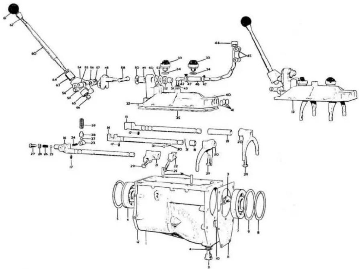
FIG. 6.4. COMPONENTS OF LATER MK 2, 240 AND 340 GEARBOX CASING
1 Gearbox casing
2 Oil drain plug
3 Oil filter plug
4 Fibre washer
5 Circlip
6 Ballbearings
7 Ballbearings
8 Circlip
9 Collar
10 Fibre washer
11 Gasket
12 Gasket
13 Remote control
14 Striking rod, first/second gears
15 Striking rod, third/top gears
16 Striking rod, reverse gear
17 'O' ring
18 Stop
19 Stop
20 Changespeed fork
21 Changespeed fork
22 Locating arm
23 Plunger
24 Spring
25 Ball
26 Spring
27 Setscrew
28 Nut
29 Dowel screw
30 Roller
31 Ball
32 Top cover
33 Switch
34 Gasket
35 Gasket
36 Dowel
37 Ball
38 Plunger
39 Spring
40 Spring
41 Welch washer
42 Breather elbow
43 Nut
44 Gearbox breather assembly
45 Distance piece
46 Hose
47 Clip
48 Pivot jaw
49 Bush
50 Fibre washer
51 Self-locking nut
52 Spring washer
53 D-washer
54 Selector lever
55 Bush
56 Fibre washer
57 Spring washer
58 Pivot pin
59 Self-locking nut
60 Changespeed lever
61 Knob
62 Cone
63 Upper bush
64 Washer
65 Lower bush
66 Self-locking nut

FIG.6.5. THE GEARS, JC GEARBOX
1 Mainshaft
2 Nut
3 Tab washer
4 Reverse gear
5 1st speed gear
6 Bearing sleeve
7 Needle roller
8 Spacer
9 Synchro hub
10 Operating sleeve
11 Thrust member
12 Plunger
13 Detent ball
14 Spring
15 Synchro ring
16 2nd speed gear
17 3rd speed gear
18 Needle
19 Spacer
20 Spacer
21 Synchro hub
22 Operating sleeve
23 Thrust member
24 Plunger
25 Detent ball
26 Spring
27 Synchro ring
28 Nut
29 Tab washer
30 Plug
31 Constant pinion shaft
32 Roller bearing
33 Spacing
34 Oil thrower
35 Nut
36 Tab washer
37 Reverse spindle
38 Key
39 Reverse idler gear
40 Lever assembly
41 Setscrew
42 Fibre washer
43 Tab washer
44 Reverse slipper
45 Split pin
46 Countershaft
47 Key
48 Gear unit (cluster)
49 Needle roller
50 Retaining ring
51 Thrust washer (rear)
52 Thrust washer (front)
53 Thrust washer (outer)


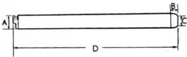
FIG.6.6. DUMMY COUNTERSHAFT
A .979" (24.86 mm)
B .5" (12.7 mm)
C .75" (19.05 mm)
D 11.125" (28.25 cm)
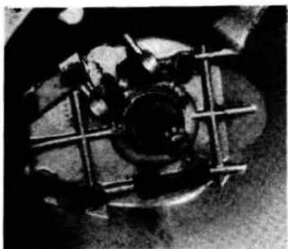
natural_image
Close-up of a mechanical component with no visible text or symbols3.2. Attachment of clutch housing to gearbox
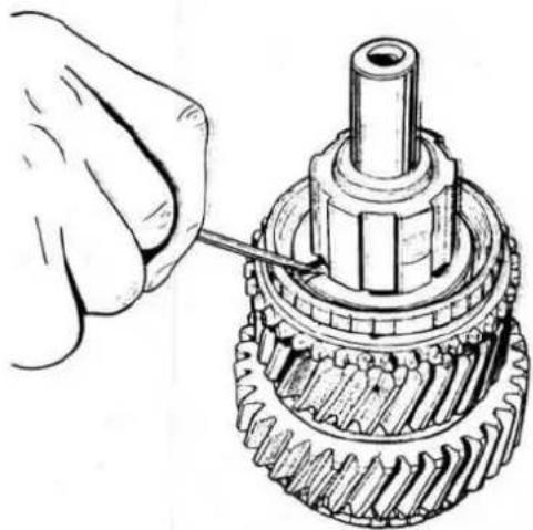
natural_image
Hand turning a gear into a mechanical shaft (no text or symbols visible)Fig.6.7. Depressing the third speed thrust washer locking plunger
natural_image
Black-and-white photo of a person in a dimly lit room, possibly at night or night (no visible text or symbols)3.3. Clutch housing and gearbox separated

natural_image
Close-up of a mechanical device with visible internal components and hands (no text or symbols)3.5. Top cover removed

natural_image
Black and white photo of a hand holding an object, possibly a device or tool, with no visible text or symbols.3.8. Retainer plate
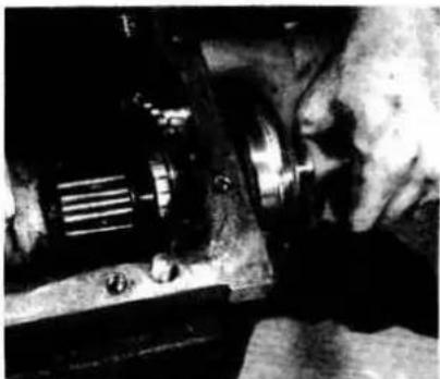
natural_image
Close-up of a mechanical assembly with gears and bolts (no visible text or symbols)3.12a. Removing the constant pinion shaft

natural_image
Close-up of a mechanical device with gears and a wooden base (no visible text or symbols)3.12b. Removing the needle roller bearing

natural_image
Close-up of a mechanical component with visible internal structure and textured surface (no text or symbols)3.13a. Removing the circlip - mainshaft bearing

natural_image
Close-up of a mechanical component with reflective surfaces and a circular hole (no visible text or symbols)3.13b. The washer and shims

natural_image
Nighttime outdoor scene with indistinct structures and dark terrain (no visible text or symbols)3.14a. Removing the rear bearing - 1

natural_image
Close-up of a mechanical component with no visible text or symbols3.14b. Removing the rear bearing - 2
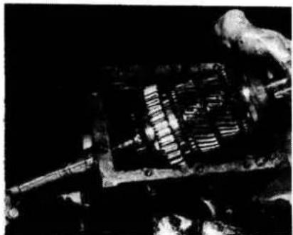
natural_image
Black-and-white photo of a mechanical device with internal components, possibly a motor or gear assembly (no visible text or symbols)3.15. Removing the mainshaft gears
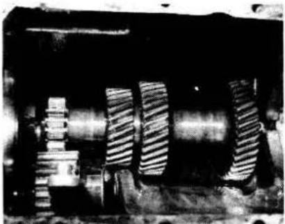
natural_image
Close-up of mechanical gears and shafts in a factory setting (no visible text or symbols)3.16. The layshaft cluster
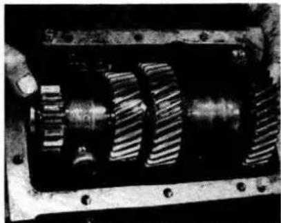
natural_image
Close-up of a mechanical gear assembly with multiple teeth and central shaft (no visible text or symbols)3.17. Lifting out the layshaft cluster
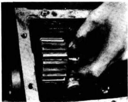
natural_image
Close-up of a hand pressing down on a mechanical component with a metallic grille (no visible text or symbols)3.18. Removing the reverse gear
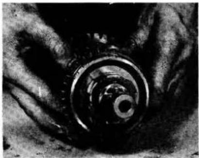
natural_image
Close-up of hands operating a mechanical component with concentric rings and a central hole (no visible text or symbols)3.24. Removing the thrust washer
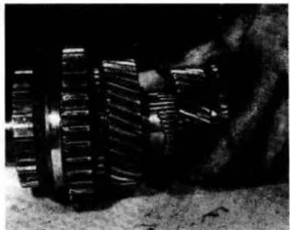
natural_image
Close-up of mechanical gears and shafts in a dark environment (no visible text or symbols)3.25. Removing the 3rd speed gear
29 When dismantling the mainshaft take careful note of the positions from which sets of needle roller bearings are removed because they are graded in size and must be kept in sets for reassembly to the positions from which they were removed.
30 Slide off the reverse gear.
31 Withdraw the first gear and collect the 120 needle rollers, the spacer and the sleeve.
32 Withdraw the 1st/2nd gear synchro assembly and collect the two synchro rings.
33 Remove the second gear with its 106 needle rollers. Leave the spacer on the mainshaft.
34 Knock back the tab of the washer locking the nut securing the 3rd/top synchro assembly to the mainshaft. Remove the nut and withdraw the synchro assembly from the shaft at the same time collecting the two loose synchro rings.
35 Withdraw the third gear with its 106 needle rollers.
36 To dismantle the synchro assembly used with JC and JCN boxes, completely surround the assembly with a cloth so that
none of the balls and springs are lost. Push out the hub from the operating sleeve and collect the synchro balls and springs, the thrust members, plungers and springs.
37 To dismantle the constant pinion shaft of JC gear boxes, open the tab washer and remove the large nut, tab washer and oil thrower. Tap the shaft smartly against a metal plate to dislodge the bearing and the spacer. The same procedure is followed for GB (JS) boxes except that in this case double locking is provided in the shape of a locknut in addition to the tab washer.
38 The constant pinion shaft of GB series gearboxes is dismantled by removing the circlip by the packing washer, any shims which may be fitted and then the oil thrower. Remove the bearing by tapping the shaft smartly against a metal plate.
39 To dismantle the top cover, first remove the gear lever, if this was not done at engine removal, by unscrewing the self locking nut and then taking off the double coil spring washer, flat washer and fibre washer and then the gear lever can be lifted off. 40 Break the locking wire and unscrew the selector rod retaining
screws.
41 Withdraw the 3rd/top selector rods with the selector, spacing tube and interlock ball. Take note of the loose interlock pin at the front of the 1st/2nd selector rod.
42 Withdraw the reverse selector rod and collect the reverse fork, the stop spring and detent plunger.
43 Withdraw the 1st/2nd selector rod with its fork and short spacer tube.
4 Gearbox - examination
1 It is assumed that the gearbox has been dismantled because of some malfunction, possibly excessive noise, ineffective synchromesh or failure to stay in a selected gear. The cause of most gearbox faults is failure of the needle rollers on the input or the mainshaft and wear on the synchro rings. These items can be replaced but there is always the possibility of some obscure fault remaining even after a visually unserviceable component has been renewed which means that all your work has gone for nothing as the fault, if any, will not be discovered until the gearbox has been re-installed in the car. It is worthwhile, therefore, if faults are found, to enquire about the availability of parts and their cost and it may still be worth considering, even at this stage, fitting an exchange gearbox.
2 Examine the teeth of all gears for signs of uneven or excessive wear and, of course, chipping. If a gear on the mainshaft is in doubtful condition, check that the corresponding gear on the layshaft is not equally damaged.
3 All gears should be a good running fit in the shaft with no signs of rock and the hubs should not be a sloppy fit on the splines.
4 Examine the selector forks for signs of wear or ridging on the faces which contact the operating sleeve.
5 Look for wear on the selector rods.
6 It is difficult to decide on the degree of wear on roller bearings but we advise taking no chances. Considering the work entailed in removing and dismantling the gearbox, it would be very short sighted not to replace all bearings as a matter of course and the same applies to all oil seals and synchroniser rings.
5 Gearbox - reassembly of type GB and GBM
1 On those gearboxes without a suffix or suffix "O" or "CR", the first task is to build up the layshaft. Press the 2nd and 3rd gears on to the splined extensions of the 1st gear and retain them with their circlip.
2 Fit the 2nd gear circlip below the circlip groove and press the constant mesh gear on as far as possible. Fit the split ring and then draw the gear forward onto it and finally fit the circlip behind the constant gear.
3 For both types of layshaft, liberally coat the needle roller retaining rings with vaseline and then fit one to each end of the layshaft gear unit followed, at each end, by the 29 rollers.
4 Fit the outer roller retaining ring at the front end and the inner and outer thrust washers at either end of the gear unit and then lower the gears into the case and insert a dummy counter-shaft to locate the layshaft gears in place.
5 The end float of the layshaft must now be checked by measuring the clearance between the thrust washer and the casing at the rear of the shaft as shown in Fig.6.8. The end float should be 0.002" - 0.004" (0.05 - 0.10 mm). Adjustment is effected by an exchange of thrust washers which are available in thicknesses of 0.152", 0.156", 0.159", 0.162" and 0.164" (3.86, 3.96, 4.04, 4.11 and 4.17 mm).
6 Remove the dummy countershaft and insert a thin rod in its place.
7 Place the reverse gear in position and draw it rearwards as far as possible to give clearance for final positioning of the layshaft gear unit.
8 Now start work on the mainshaft. Liberally coat the 41
needle rollers with vaseline and then fit them behind the shoulder on the mainshaft and slide the 2nd speed gear, with synchronising cone to the rear, on to them.
9 Fit the 2nd speed thrust washer spring and plunger into the plunger hole and then slide the thrust washer up the shaft and over the splines. Align the large hole in the synchro cone, compress the plunger and rotate the thrust washer into the locked position with the cut-away in line with the plunger.
10 Now check the end float of the 2nd gear on the mainshaft by measuring, with a feeler gauge, the distance between the thrust washer and the shoulder on the mainshaft. The clearance should be 0.002" - 0.004" (0.05 - 0.10 mm) and if this is not achieved, remove the thrust washer and replace it by one which will give the required clearance. Washers are available in the following thicknesses:-
0.471 in/0.472 in (11.96/11.99 mm)
0.473 in/0.474 in (12.01/12.03 mm)
0.475 in/0.476 in (12.06/12.09 mm)
11 The above work in respect of the 2nd speed gear is now repeated to fit the 3rd speed gear on the opposite side of the shoulder on the mainshaft. End float is checked in the same manner as for the 2nd speed gear and the same range of adjusting shims is available. The holes through which the thrust washer locking plungers are depressed are shown in Fig.6.9.
12 To assemble the 2nd gear synchro assembly, first fit the springs and balls and shims, if fitted to the six blind holes in the synchro sleeve.
13 Refer to Fig.6.10 and fit the 1st speed gear to the 2nd speed synchronising sleeve so that the relieved tooth of the internal splines in the gear are in line with the stop pin in the sleeve.
14 It may be helpful to compress the springs using a jubilee clip and then slide the operating sleeve over the synchronising sleeve until the balls can be heard and felt to engage the neutral position groove.
15 It should require 62 to 68 lbs (28 to 31 kg) pressure to disengage the synchronising sleeve from the neutral position in the operating sleeve. This can be judged, if special equipment is not available, by gripping the operating sleeve in the palms of the hands and then pressing the synchronising sleeve with the fingers until it disengages from the neutral position. It should require firm finger pressure before disengaging and, if necessary, shims can be fitted, or removed from, underneath the springs to adjust the pressure of the balls against the operating sleeve.
16 Now fit the 1st speed gear/2nd speed synchro assembly to the mainshaft using any spline position and check that the synchro sleeve moves freely on the mainshaft when the ball and plunger is not fitted. If there is any restriction, try the sleeve on different splines on the shaft and if there is no improvement, check for burrs on the splines and rectify as required.
17 Take the synchro assembly off the mainshaft, fit the ball and plunger and then refit it to the shaft in the position from which it was removed.
18 Support the shaft in a vice (with protected jaws) and check the interlock plunger by sliding the outer operating sleeve into the 1st gear position as shown in Fig.6.11. Apply slight downward pressure on the synchro assembly and at the same time rotate the 2nd speed gear. It should rotate freely without any tendency for the synchro cones to rub but if restriction is felt, a longer plunger should be fitted to the synchro sleeve. Plungers are available in the following lengths:-
0.490 in, 0.495 in and 0.500 in (12.4, 12.52 and 12.65 mm) 19 The 3rd/top synchro assembly is put together, and is tested for operation, in the same manner as the 2nd gear synchro assembly but make sure that the wide chamfer end of the operating sleeve faces the large boss end of the inner synchronising sleeve as shown in Fig.6.12 and that the two relieved teeth in the operating sleeve are in line with the ball and plunger holes as illustrated in Fig.6.13.
20 The 3rd/top synchro assembly is now ready for fitting to the mainshaft.
21 Note the following points when fitting the assembly to the mainshaft:-
a) there are two transverse grooves on the mainshaft splines and
the relieved tooth on the wide chamfer end of the outer operating sleeve must be in line with the foremost groove in the mainshaft as shown in Fig.6.14. Incorrect alignment will result in the locking plungers engaging the wrong grooves and so prevent full engagement of top and 3rd gear.
b) The wide chamfer end of the outer operating sleeve must face forwards, that is, towards the constant pinion shaft end of the gearbox.
c) The inner sleeve must slide freely on the mainshaft when the balls and plungers are not fitted. If there is any restriction, check the splines for burrs and rectify as necessary.
22 Fit the two balls and plungers to the holes in the inner synchro sleeve and then fit the assembly to the mainshaft in the manner indicated in the preceding paragraph.
23 Support the mainshaft in a vice (with protected jaws) and check the operation of the interlock plungers by sliding the 3rd/top operating sleeve over the 3rd speed gear dogs as shown in Fig.6.15. With 3rd gear engaged, lift and lower the synchro assembly; it should be possible to move it about 3/32" (2.5 mm) without any drag being felt. If it does not move freely, a shorter 3rd speed plunger should be fitted, this is the plunger which, when looking at the wide chamfer end of the outer operating sleeve, is not opposite the relieved tooth in the operating sleeve. Plungers are available in the following lengths:
0.490 in, 0.495 in and 0.500 in (12.4, 12.52 and 12.65 mm). 24 Now slide the operating sleeve into the top gear position as shown in Fig.6.16 and again lift and lower the synchro assembly; it should be possible to move the assembly about 3/16" (4.5 mm) without any drag being felt and also, with slight downward pressure on the assembly, the 3rd speed gear should be free to rotate without any tendency for the cones to rub.
25 Fit a shorter top gear plunger if the synchro assembly does not move freely when lifted and lowered. A longer top gear plunger should be fitted if the 3rd gear synchro cones are felt to rub, this plunger is the one in line with the relieved tooth in the operating sleeve looking from the wide chamfer end of the outer operating sleeve. Plungers are available in the lengths quoted in paragraph 23.
26 Now for assembly of the constant pinion shaft. On "JS" suffix gearboxes, fit the oil thrower followed by the ballrace on to the shaft with the circlip and collar fitted to the outer track of the bearing. Screw on the nut and fit the tab washer and locknut. Finally fifit the roller race into the shaft spigot bore. Assemble the constant pinion shaft of other suffix gearboxes in the same manner but in this case where the oil thrower assembly is retained by a circlip, fit shims as required to eliminate all end float between the circlip and the assembly.
27 The gears are now ready for assembly to the casing in which the layshaft cluster and the reverse gear have already been positioned. Enter the mainshaft through the top of the casing and move it rearwards through the bearing hole in the case.
28 Fit a new gasket to the front face of the casing and insert the constant pinion shaft at the front of the case with the cutaway portions of the toothed driving member facing the top and bottom of the casing. Tap the shaft to the rear until the collar and circlip on the bearing butt against the casing.
29 Hold the constant pinion shaft in position and tap in the rear bearing complete with its circlip.
30 Lift the layshaft cluster into mesh using the thin rod which should still be in position and then insert the dummy countershaft through the bore in the front face of the casing as illustrated in Fig.6.17.
31 Engage top and first gears. On non-overdrive gearboxes, fit the Woodruff key and the speedometer drive gear to the mainshaft followed by the tab washer and locknut. Screw up the nut and lock with the tab washer. On gearboxes fitted with overdrive, fit as many shims as may be required to eliminate all end float from the mainshaft followed by the plain washer and circlip behind the rear bearing. Fig.6.18 illustrates the rear bearing retaining arrangements for the two gearboxes.
32 Fit a new gasket to the rear face of the gearbox and then offer up the extension complete with the counter and reverse shafts and tap it into position at the same time pushing out the
dummy countershaft. Secure the extension with its seven set-screws and spring washers.
33 Fit the overdrive unit as described in Section 20.
34 Fit a new fibre washer at the front end of the countershaft.
35 Fit the speedometer driven gear and bearing to the extension. 36 Reassemble the top cover in the reverse order to the dismantling procedure given in paragraphs 39-43 of Section 3 but do not forget to fit the interlock balls and pins and it is advisable to fit new "O" rings on the selector rods. The reverse plunger will require adjustment and this is done by first fitting the plunger and spring. Now fit the ball and spring and enter the screw and locknut. Press the plunger in as far as possible and tighten the screw to lock it. Slowly slacken the screw until the plunger is released and the ball engages with the circular groove in the plunger and at this point, hold the screw from turning and tighten the locknut.
37 Fit a new gasket to the top of the gearbox.
38 Ensure that the gears and the gear selectors of the top cover are in neutral and that the reverse idler gear is out of mesh with the reverse gear.
39 Now refit the top cover making sure that the selector forks mate with the grooves in the synchro assemblies. Secure the cover with the nuts and bolts noting that the bolts are of different lengths.
40 Fit a new oil seal to the clutch housing with the lip of the seal facing the gearbox. Attach the clutch housing to the gearbox with its eight bolts and three tabbed locking plates noting that the two bolts located adjacent to the clutch fork trunnions are secured with locking wire (use soft iron locking wire). Tighten the bolts evenly and then lock them with the tabs or locking wire, as applicable.

natural_image
Cross-sectional diagram of a mechanical gear assembly with a hand adjusting the component (no text or labels visible)Fig.6.8. Checking layshaft end float

natural_image
Technical line drawing of a mechanical gear assembly (no text or symbols)Fig.6.9. Showing the holes through which the thrust washer locking plungers are depressed
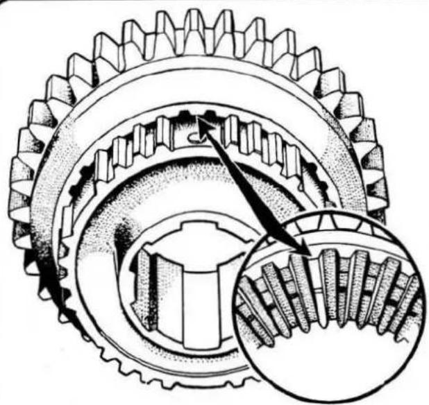
natural_image
Technical illustration of a gear assembly showing teeth and internal components (no text or labels)Fig.6.10. Alignment of the relieved tooth and the stop pin

natural_image
Technical line drawing of a mechanical gear assembly (no text or symbols)Fig.6.13. The relieved tooth must be in line with the ball and plunger holes
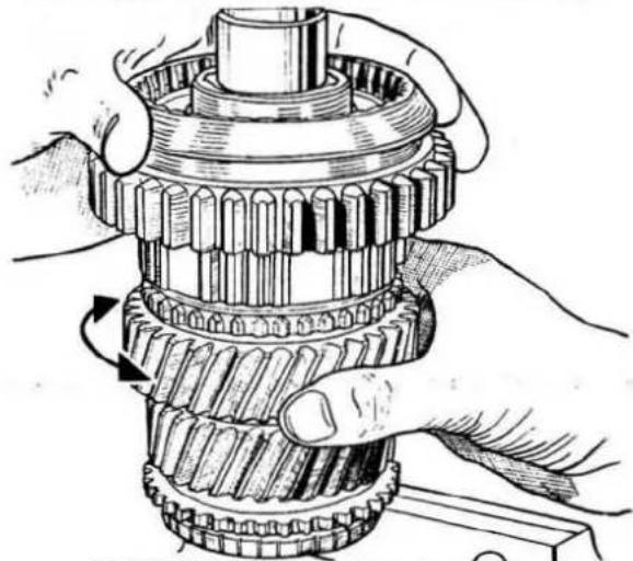
natural_image
Technical illustration of hands operating a mechanical gear assembly (no text or symbols present)Fig.6.11. Checking the 2nd speed gear for freedom

natural_image
Technical line drawing of a mechanical gear assembly with cross-section view (no text or labels)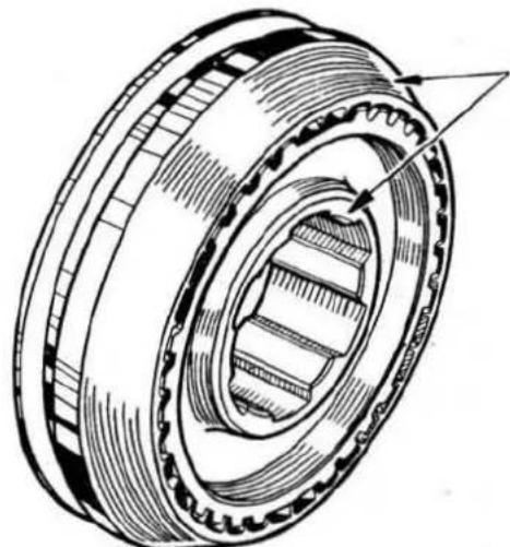
natural_image
Technical line drawing of a mechanical bearing assembly (no text or symbols)Fig.6.12. Assembly of the operating sleeve to the inner synchronising sleeve
Fig.6.14. Location of the operating sleeve on the mainshaft

Fig.6.15. Checking operation of the interlock plungers
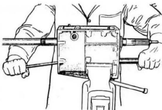
natural_image
Line drawing of hands operating a mechanical tool with a central component (no text or symbols)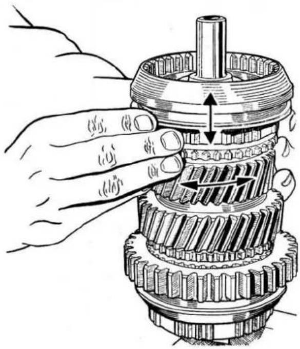
natural_image
Illustration of a hand turning a gear mechanism with arrows indicating rotational direction (no text or symbols present)Fig.6.16. Checking 4th (top gear) interlock plunger and assembly
Fig.6.17. Fitting the dummy countershaft

natural_image
Technical cross-sectional diagram of a mechanical assembly (no text or labels)STANDARD GEARBOX

OVERDRIVE GEARBOX
Fig.6.18. Retention of the rear bearing
41 Engage a low gear and then refit the flange for the propeller shaft securing it with its nut and tab washer.
42 Refit the gearbox and overdrive drain plugs and also the gearbox filler plug if this was removed. It is advisable to fit new fibre washers to the plugs.
6 Gearbox - reassembly of type JC and JCN
1 Start with the synchro assemblies for which the assembly procedure for 1st/2nd and 3rd/Top is the same but note that although the 3rd/Top and 1st/2nd synchro hubs are similar in appearance they are not identical. To distinguish them, a groove is cut on the edge of the 3rd/Top hub as illustrated in Fig.6.19.
2 Assemble the synchro hub to the operating sleeve so that the wide boss of the hub is on the opposite side to the wide chamfer end of the sleeve as depicted in Fig.6.20, and so that the three balls and springs will be in line with the teeth having three detent grooves (Figs.6.21 and 6.22).
3 Pack up the synchro hub so that the holes for the ball and springs are exactly level with the top of the operating sleeve as shown in Fig.6.23.
4 Fit the three springs, plungers and thrust members to their correct positions and press down the thrust members as far as possible. Fit the three springs and balls to the remaining holes. It may help to keep the plungers and balls in position if the springs are liberally coated with vaseline.
5 Compress the springs with a large jubilee clip, a piston ring clamp is ideal, as shown in Fig.6.24. Depress the hub slightly and then push down the thrust members with a screwdriver until they engage the neutral groove in the operating sleeve.
6 Tap the hub down evenly and carefully until the balls can be heard, and felt, to engage the neutral groove.
7 Now start assembling the layshaft cluster gear by fitting one retaining ring in the front end of the cluster.
8 Liberally coat the 29 needle rollers with vaseline and place them in the front position of the cluster followed by the front inner thrust washer but make sure that the peg on the washer locates in the groove machined in the front face of the cluster gear.
9 Fit the retaining ring, the 29 needle rollers and the second retaining ring to the rear of the cluster.
10 Fit the slipper to the reverse idler lever and secure it with a new split pin. Assemble the lever to the casing and secure it in position with its setscrew and lock with the tab washer.
11 Liberally coat the rear thrust washer with vaseline and then place it on its boss in the casing making sure that the peg locates correctly.
12 Coat the front outer thrust washer with vaseline and place it in position on the cluster and now lower the layshaft cluster carefully into position.
13 Insert a dummy countershaft into the bore in the casing and through the cluster gear and the next task is to check the end float of the cluster by measuring the clearance between the rear thrust washer and the cluster.
14 The end float should be 0.004" - 0.006" (0.10 - 0.15 mm). Adjustment is made by replacement of the outer front thrust washer which is available in the following thicknesses:-
0.152 in, 0.156 in, 0.162 in and 0.164 in (3.86, 3.96, 4.04, 4.11 and 4.17 mm).
15 The constant pinion shaft assembly should now be put together by fitting a new oil thrower, tab washer and locknut. Tighten down on the nut and secure with the tab. Fit the spacer to the other end of the assembly followed by the roller bearing. 16 The mainshaft is reassembled in the reverse order to the dismantling procedure given in Section 3. You may find it helpful to fit a jubilee clip to the shaft in order to prevent the reverse gear sliding off when assembling the shaft to the casing. Do make sure that the correct set of needle rollers are fitted to their individual gears; they are graded on diameter and rollers of one grade only must be used for an individual gear.
17 The end float of the gears must be checked and details of the permissible clearances will be found under "Specifications" at
the beginning of this Chapter. If the end float is found to be excessive it can only be rectified by the fitment of new parts. 18 From this point onwards follow the instructions given in Section 5 paragraphs 27-42 to complete assembly of the gearbox. However, in this case the oil pump (Fig.6.25) must be refitted to the rear extension of JC boxes. Refit the gears to the

natural_image
Cross-sectional diagram of a mechanical gear assembly showing rotational and linear motion paths (no text or labels)Fig.6.19. Identification grooves, 3rd/top synchro assembly

natural_image
Technical line drawing of a mechanical gear assembly with teeth and central bore (no text or labels)Fig.6.20. Assembly of the synchro hub and operating sleeve

natural_image
Technical illustration of a mechanical gear assembly with exploded view (no text or labels)Fig.6.21. Showing the relative positions of the detent ball, plunger and thrust member

natural_image
Cross-sectional illustration of a mechanical gear assembly (no text or labels)Fig.6.22. Assembling the synchro hub to the sleeve

natural_image
Technical cross-section diagram of a mechanical gear assembly (no text or labels)Fig.6.23. Fitting the springs, plungers and thrust members

natural_image
Technical line drawing of a mechanical gear assembly (no text or symbols)Fig.6.24. Use of a jubilee clip to compress the springs
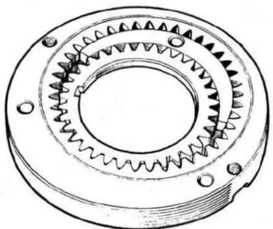
natural_image
Technical line drawing of a mechanical gear assembly (no text or symbols)Fig.6.25. The oil pump
pump in accordance with your marks made when dismantling, coat the gears and the pump body with oil and then secure the assembly to the extension with the three setscrews and lock them by staking using a centre punch.
19 After refitting the engine and the gearbox to the car, run the car in top gear as soon as possible in order to attain the necessary mainshaft speed to prime the oil pump.
7 Overdrive unit - general description
A Laycock de Normanville "A" Type overdrive unit is used in conjunction with the GBN gearbox whilst an "A" Type Compact unit is fitted to the JCN four speed synchromesh gearbox. Although the operation, routine maintenance etc: of the two units is similar the construction differences are such that different procedures must be adopted when dismantling and reassembling them.
The overdrive unit comprises a hydraulically controlled epicyclic gear housed in a casing which is attached to an adaptor at the rear of the gearbox. The specially extended gearbox driven (or input shaft) carries at its end the inner member of a unidirectional clutch, the outer member of the clutch is carried in the combined annulus and output shaft. The input shaft also carries the planet carrier and a freely rotatable sun wheel, splined to the forward extension of which, and sliding on it, is a cone clutch member. The inner lining of the cone clutch engages the outside of the annulus whilst the outer lining engages a cast iron brake ring sandwiched between the front and rear parts of the
unit housing. This set-up is shown in Fig.6.26.
The cone clutch is held in contact with the annulus by a number of compression springs and this locks the sun wheel to the annulus so that the entire gear train rotates as a solid unit to give direct drive. With the unit in this condition, the drive is taken through the unidirectional clutch whilst the cone clutch takes over-run and reverse torque and so prevents a free wheel condition.
Operation of the overdrive switch causes oil under pressure to move two pistons, through the operating valve (Fig.6.27) housed in cylinder in the unit housing, to overcome the pressure of the springs and this causes the cone clutch to engage the stationary brake ring and bring the sun wheel to rest. This allows the annulus to over-run the unidirectional clutch and so give an increased speed to the output shaft ie "overdrive".
Exploded views of the "A" Type and the "A" Type Compact overdrive units are given in Figs.6.28, 6.29 and 6.30.
The two types of overdrive unit are not interchangeable between the GBN and the JCN gearboxes.
The oil for lubrication and operation of the overdrive is fed from the gearbox casing and so a check of the level of oil in the gearbox also checks the level of oil in the overdrive unit. However, the overdrive unit is hydraulically operated and even small particles of dirt can cause malfunctioning so absolute cleanliness must be observed when replenishing the gearbox with oil. One point to remember is that although the gearbox and the overdrive have a common lubrication system, the overdrive unit is not drained when the gearbox is drained; it has its own drain plug.
8 Overdrive unit - removal from the gearbox
1 Before commencing any dismantling operations it is important that hydraulic pressure is released from the system by operating the overdrive 10 or 12 times.
2 Drain the oil from the system, if this was not done at engine removal, by removing the drain plug, and allowing the oil to drain into a container.
3 The following paragraphs refer to the "A" Type unit.
4. The unit is attached to the adaptor at the rear of the gearbox by seven studs two of which are extra long.
5 Remove the nuts on the short studs.
6 Slacken the two nuts on the long studs by equal amounts to release the compression of the clutch springs (photo).
7 Carry on removing the two nuts by equal amounts each until spring compression is competely released and then take off the nuts and remove the unit from the gearbox (photo).
8 The following paragraphs refer to the "A" Type Compact unit.
9 Remove the nuts from the four short studs and from the two long studs at the bottom of the unit.
10 There is no spring tension to release so after removal of the nuts, and their spring washers, the unit can be lifted off leaving the adaptor in place on the gearbox.
9 Overdrive unit "A" Type - dismantling
It is essential to maintain absolute cleanliness throughout all operations. Even minute particles of dirt or lint from cleaning cloths may cause damage or, at best, malfunctioning of the unit.
1 Thoroughly clean down the outside of the unit.
2 Prepare a clean area on which to lay out components as they are removed and have some clean containers handy to hold the smaller parts.
3 Take the clutch springs off their pins and note the positions from which they were removed. You will find that of the eight springs fitted to the 2.4 and 3.4 litre cars, the four inner springs are shorter than the four outers. Of the twelve springs fitted to 3.8 litre models, four short ones are located in the centre and the remaining eight are around the outside.
4 Knock up the tab washer locking the nuts to the two bridge

Fig.6.26. The principle of operation of the overdrive unit

Fig.6.27. The principle of the operating valve

FIG.6.28. THE FRONT CASING ASSEMBLY 'A' TYPE UNIT
1 Extension for attachment to gearbox
2 Gasket
3 Bearing spacing washer
4 Circlip
5 Front casing
6 Welch washer plug
7 Operating valve shaft
8 Operating valve cam lever
9 Cam lever pin
10 'O' ring seals
11 Operating and restrictor valve
12 Operating valve ball
13 Ball plunger
14 Plunger spring
15 Valve and pressure take-off plug
16 Copper washer
17 Pump guide peg
18 Valve setting lever
19 Setting lever pin
20 Stud
21 Stud
22 Long gearbox stud
23 Rear casing stud
24 Operating valve shaft collar
25 Breather plug
26 Pump plunger
27 Pump body
28 Pump plunger spring
29 Pump plug
30 Pump securing screw
31 Spring washer
32 Non-return valve ball
33 Ball plunger
34 Plunger spring
35 Screwed plug
36 Sealing washer
37 Gauze filter
38 Drain plug
39 Sealing washer
40 Pump operating eccentric
41 Cone clutch operating piston
42 Piston bridge piece
43 Nut
44 Tab washer
45 Accumulator piston assembly
46 Set of six piston rings, four narrow, two wide
47 Piston housing
48 3.8 litre spacer tube
18a 2.4 and 3.4 litre spacer tube
49 3.8 litre piston spring (large)
50 3.8 litre piston spring (small)
50a 2.4 and 3.4 litre piston spring
51 Solenoid mounting bracket assembly
52 Rubber buffer for solenoid plunger
53 Gasket
54 Nut
55 Spring washer
56 Bolt, holding accumulator spring in tension
57 Solenoid lever
58 Pinch bolt
59 Nut
60 Spring washer
61 Cover plate
62 Gasket
63 Operating solenoid
64 Bolt
65 Spring washer
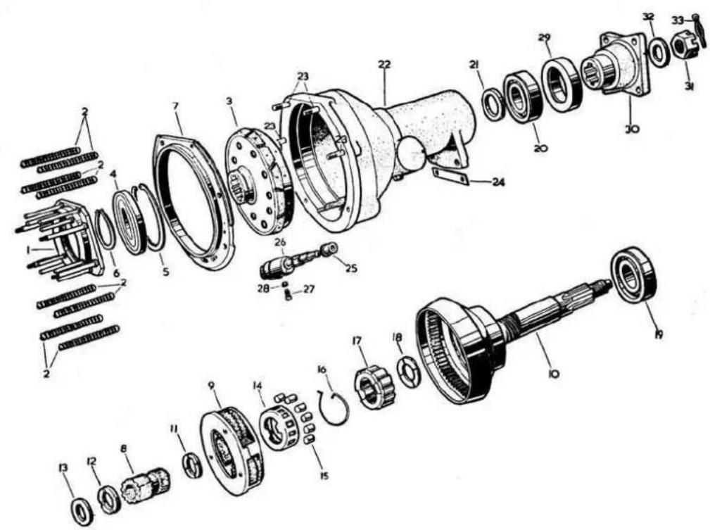
FIG.6.29. THE REAR CASING ASSEMBLY 'A' TYPE UNIT
1 Clutch thrust ring assembly
2 Springs
3 Sliding member
4 Ball bearing
5 Circlip
6 Circlip
7 Brake ring
8 Sun wheel assembly
9 Planetary carrier assembly
10 Annulus assembly
11 Thrust washer (phospher bronze)
12 Thrust washer (phospher bronze)
13 Thrust washer (steel)
14 Cage for uni-direction clutch
15 Rollers
16 Spring
17 Inner member for uni-directional clutch
18 Thrust washer
19 Ball bearing
20 Ball bearing
21 Spacing washer
22 Rear casing assembly
23 Stud
24 Packing
25 Pilot bush
26 Speedometer drive assembly
27 Locking screw
28 Spring washer
29 Oil seal
30 Flange
31 Nut
32 Plain washer
33 Split pin
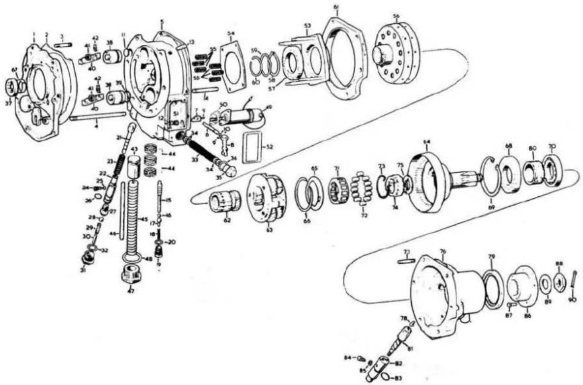
FIG.6.30, THE 'A' TYPE COMPACT OVERDRIVE UNIT
1 Adaptor plate
2 Gasket
3 Stud
4 Stud
5 Front casing
6 Main operating valve shaft
7 Cam
8 Lever
9 Roll pin
10 'O' ring
11 Welch washer
12 Rubber stop
13 Breather
14 Stud
15 Main operating valve
16 Ball 5/16" dia.
17 Plunger
18 Spring
19 Plug
20 Copper washer
21 Oil pump plunger
22 Body
23 Spring
24 Screw
25 Fibre washer
26 'O' ring
27 Non-return valve body
28 Ball 7/32" dia.
29 Spring
30 Support rod
31 Plug
32 Copper washer
33 Filter
34 Magnetic ring
35 Plug
36 Washer
37 Oil pump operating cam
38 Operating piston
39 'O'ring
40 Bridge piece
41 Nut
42 Tab washer
43 Accumulator piston
44 Piston ring
45 Spring
46 Support rod
47 Plug
48 Washer
49 Solenoid
50 Gasket
51 Nut
52 Gasket
53 Thrust ring
54 Retaining plate
55 Springs
56 Sliding member
57 Ball bearing
58 Circlip
59 Corrugated washer
60 Snap ring
61 Brake ring
62 Sunwheel
63 Planetary carrier
64 Annulus
65 Oil thrower
66 Spring ring
67 Spring clip
68 Ball bearing
69 Circlip
70 Ball bearing
71 Cage for uni-directional
clutch
72 Rolle
73 Cage spring
74 Inner member
75 Thrust washer
76 Rear casing
77 Stud
78 Thrust button
79 Oil seal
80 Speedometer driving gear
81 Speedometer driven gear
82 Bearing assembly
83 'O' ring
84 Screw
85 Copper washer
86 Flange
87 Bolt
88 Slotted nut
89 Washer
90 Split pin
pieces against which the two pistons bear. Remove the nuts and take off the bridge pieces (photo).
5 Withdraw the two operating pistons (photo).
6 Remove the six nuts securing the two halves of the housing and then separate them (photo).
7 Remove the brake ring which is located over the studs securing the two halves of the unit (photo).
8 Now lift off the extension, with its studs, which locate the unit on the gearbox (photo) together with the clutch sliding
member assembly.
9 Lift off the steel and phosphor bronze thrust washers from the sunwheel assembly (photo).
10 Take out the sunwheel and the planet carrier assembly (photo).
11 The annulus assembly complete with the cage and roller bearing for the unidirectional clutch and the inner member of the unidirectional clutch with thrust washer can now be taken out by tapping through the bearing at the rear of the unit (photo).

natural_image
Close-up of a mechanical component with textured surfaces and no visible text or symbols8.6. Remove the nuts from the long studs
natural_image
Close-up of a mechanical component with no visible text or symbols8.7. Separating the gearbox and the 'A' type unit
natural_image
Close-up of a mechanical component with no visible text or symbols9.4. Removing the bridge pieces

natural_image
Close-up of mechanical components with no visible text or symbols9.5. Removing the pistons

natural_image
Black-and-white abstract image showing a dark, curved structure with circular elements and textured background (no text or symbols)9.6. Separating the front and rear casing

natural_image
Close-up of a mechanical component with no visible text or symbols9.7. Taking off the brake ring
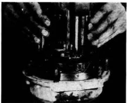
natural_image
Close-up of hands operating a mechanical device with no visible text or symbols9.8. Taking off the extension

natural_image
Close-up of a mechanical component with a cylindrical shaft and flange (no visible text or symbols)9.9. The steel and bronze washers on the sun wheel

natural_image
Close-up of hands assembling a mechanical gear assembly (no visible text or symbols)9.10. The sun wheel and planet carrier assembly

natural_image
Close-up of a hand pressing down on a mechanical component (no visible text or symbols)9.11. Removing the annulus assembly

natural_image
Close-up of a mechanical device with a cylindrical component and a vertical rod inserted, no visible text or symbols.9.12. Removing the propeller shaft flange
12 However, if the propeller shaft flange was not previously removed, this will have to be taken off before the annulus assembly etc can be taken out. Knock up the tab washer securing the flange nut, hold the flange from moving and then remove the nut (photo). Tap the flange off the shaft of the annulus to remove it.
13 The overdrive unit is now dismantled to major components, directions for the removal of all other items, which can be removed from the unit when installed in the car, will be found under their individual Sections later in this Chapter.
10 Overdrive unit - "A" Compact Type - dismantling
The warning given at the beginning of Section 9 concerning the necessity for maintaining absolute cleanliness during servicing operations is equally applicable to this unit.
1 Knock up the tab washers locking the four nuts which secure the piston bridge pieces. Remove the nuts and the bridge pieces.
2 Loosen the two screws securing the solenoid so that the front casing can be removed.
3 Remove the four nuts on the studs securing the front and rear casings and then separate the casings.
4 Remove the brake ring, if still attached to the rear casing, by tapping it with a hide faced mallet to release it from the studs.
5 Lift out the clutch sliding member complete with the thrust ring, bearing and sun wheel.
6 Lift out the planet carrier and the gear train.
7 Remove the operating pistons by gripping the centre boss with a pair of pliers and rotating gently whilst pulling outwards.
8 Remove the circlip from the sun wheel and slide off the corrugated washer and the sliding member.
9 Lift out the planet carrier assembly.
10 Move to the rear casing. Take off the circlip and the oil thrower and then remove the unidirectional clutch and roller bearing. A special tool (Churchill Tool No.1.178) is available for use when removing the clutch and it ensures that the rollers do not fall out of their retaining cage. The tool is used by placing it centrally over the front face of the annulus and then lifting the
inner member of the clutch up to it.
11 Remove the phosphor bronze thrust washer fitted between the hub of the clutch and the annulus.
12 Remove the speedometer dowel screw and withdraw the drive bush and the pinion.
13 Take out the split pin locking the nut securing the propeller shaft flange. Hold the flange from moving and remove the nut. Take off the flange.
14 Remove the oil seal behind the propeller shaft flange and now press the annulus forward out of the rear bearing.
15 We suggest that the front and rear bearings are not removed from the casing unless they are suspect, but to remove them, take out the circlip and then drive out the speedometer drive gear and the rear bearing. Drive out the front bearing.
16 The overdrive unit is now dismantled to major components, directions for the removal of all other items, which can be removed from the unit when installed in the car, will be found under their individual Sections later in this Chapter.
11 Overdrive unit - examination
The following instructions apply to both types of unit but owing to differences in construction some items may apply to one unit and not the other.
1 Examine the front casing for cracks or damage. The most likely place in which cracks may occur is in the region of the securing holes.
2 Look at the bores of the operating cylinders for scores or wear. Wear will probably show up as a ridge.
3 Look for signs of oil leakage at the plugged ends of the oil passages.
4 Make sure that the sealing disc in the front face of the casing is tight and is not leaking.
5 Inspect the centre bush for wear or damage. If the bush of the planet carrier is worn a complete new gear must be fitted.
6 Inspect the operating pistons for scoring, replace the sealing ring if there is any sign of damage or distortion.
7 Check the pump roller, and especially the bush, for wear.
8 Look at the pump plunger and make sure it is worn or scored.
9 Check the pump body for wear and score and also check the spring for distortion.
10 Look closely at the valve seat and the ball and make sure they are not damaged.
11 Check the accumulator piston for wear, scores and broken rings.
12 Check the accumulator spring for distortion.
13 Make sure that the operating valve slides easily in the bore of the front casing.
14 Check that the restriction jet is clear and also check the spring for distortion.
15 Clean the filter thoroughly in petrol and removal all metallic particles from the magnetic rings.
16 Check the brake rings for wear, scoring or cracks.
17 Make sure that the clutch linings on the sliding member are not worn or charred and if either fault is present, the complete sliding member must be replaced.
18 Make sure that the pins for the bridge pieces on the thrust ring are a tight fit.
19 Inspect the ball race of the sliding member for noisy rotation. This can be a source of noise when running in direct gear.
20 Check the clutch springs for distortion or signs of collapse by comparing the length of one with another.
21 Make sure that the rollers of the unidirectional clutch are not chipped and that the inner and outer members are not worn or damaged. Check that the cage, the two ears in particular, is not damaged and that the spring is not distorted or broken.
22 Check the phosphor bronze spigot bearing fitted in the annulus under the unidirectional clutch, if it is damaged a new annulus and bearing must be fitted.
23 Check the rear casing ball races for smooth running.
24 Inspect the rear oil seal, if this was removed a new seal must be fitted on reassembly.
25 Examine the teeth of the speedometer pinion for wear.
12 The operating valve - removal and refitting
1 The operating valve of "A" Type units is located on the top of the unit and access to it, when the engine is installed, is obtained by removing the gearbox cowling as decribed in Chapter 1.
2 Remove the plug (photo) and then lift out the plunger and spring.
3 Removal of the ball presents a bit of a problem but, with patience, this can be taken out by using a blob of vaseline on the end of a matchstem. Remove the restrictor valve by inserting the point of a pencil in the hole in its end.
4 The operating valve of the JCN unit is located at the bottom of the box.
5 Place the car over a pit or on a ramp or raise the car on a jack to give access to the underside of the unit. If the car is raised on a jack, make sure it is properly supported before starting work.
6 Remove the plug and then take out the spring followed by the plunger, ball and the main operating valve.
7 Refitting, in each case is the reverse of the removal sequence but it is advisable to fit new copper washers under the plug.
13 The operating valve - adjustment
1 The ball should be lifted 1/32" (0.79 mm) off its seat when the overdrive control is operated and if the ball does not lift by this amount, adjustment is required.
2 Look on the right hand side of the unit and you will see the valve setting lever which is pivoted on the operating cross shaft. In one end of the lever is a 3/16" (4.76 mm) diameter hole which should correspond with a similar hole when the unit is in

natural_image
Close-up of industrial machinery components (no visible text or symbols)12.2. The operating valve plug

natural_image
Dark, low-contrast image with no discernible text, symbols, or identifiable objects.13.3. The solenoid with bracket cover removed
'overdrive" (Fig.6.31).
3 If the holes do not line up, remove the solenoid bracket cover (photo) on the opposite side of the casing and slacken the clamp bolt shown in Fig.6.32. Rotate the shaft until a 3/16" (4.76 mm) rod (use the shank of a drill) can be passed through the hole in the lever and the hole in the casing as illustrated in Fig.6.31.
4 Tighten the clamp bolt and check on your adjustment by putting the unit out of overdrive and then switch in again and recheck on the alignment of the holes. When the solenoid is energised, its consumption should be about 1 amp. A reading of 15-20 amps indicates that the plunger is not moving far enough to switch from the operating to the holding coil and that your adjustment of the lever is incorrect.
14 The hydraulic system - faulty operation
1 If the unit fails to operate, first check that the ball valve is seating and lifting correctly.
2 Next check that the pump is operating by jacking up both rear wheels, remove the valve plug, start the engine and then engage top gear. With the engine ticking over, watch for oil being pumped into the valve chamber, if none appears it indicates that the pump is not functioning.
3 Possible sources of trouble are failure of the non-return valve due to bed seating or to a broken valve spring or breakage of the spring holding the pump plunger in contact with the cam. Either fault will entail removal of the pump valve and/or the pump. If the operating pressure is low, it may mean that the accumulator will have to be removed. All the above can be removed and refitted with the unit installed but follow the same procedure when the unit is on the bench.
15 Pump valve - removal and refitting
1 Drain the unit.
2 The valve is removed from JCN boxes by taking out the centre plug in the bottom of the unit.
3 Take out the support rod, the spring and the ball.
4 Unscrew the valve body. A special tool (Churchill Tool No.L.213) is available for this task.
5 Removal of the valve from "A" Type units is a little more complicated.
6 Remove the cover from the solenoid bracket and then remove the solenoid body by taking out the two setscrews.
7 Slacken the clamping bolt of the operating lever and remove the lever complete with the solenoid plunger.
8 Remove the distance collar from the valve operating shaft.
9 The solenoid bracket is secured by two nuts and two bolts the heads of the latter are painted red.
10 Remove the nuts from the studs before touching the bolts.
This is important as, after removing the nuts, the two bolts should be slackened off together to release tension on the accumulator spring.
11 Remove the solenoid bracket.
12 Unscrew the valve cap and take out the spring, the plunger
and the ball.
13 Refitting is the reverse of the removal sequence in each case but it will be necessary as a final step, to adjust the operating lever in the manner described in Section 13.
16 Pump - removal and refitting
1 Remove the pump valve in the manner described in Section 15.
2 Unscrew the securing bolt and remove the filter fitted to the "A" Type unit.
3 Take out the two cheese headed screws securing the pump body flange.
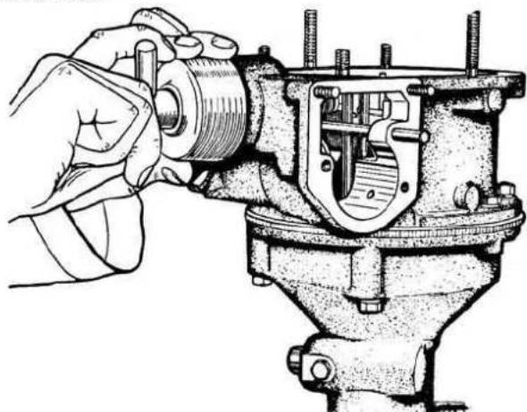
natural_image
Technical illustration of a hand operating a mechanical component with threaded parts (no text or symbols visible)Fig.6.33. Extracting the oil pump ('A' type unit)
4 Now extract the pump and for this a special tool (Churchill Tool No.L 183A with adaptor L.183A-2) is required. Removal is illustrated in Fig.6.33.
5 The pump plunger and spring will come out when the body is removed.
6 When refitting, first replace the plug in the bottom of the pump body and make sure that it is tight.
7 Align the pump body so that the inlet port and the holes for the securing screw register with the corresponding holes in the housing and then gently tap the pump body home.
8 You will find the pump plunger is prevented from rotating when in position, by a guide peg located in the front of the casing. The plunger should be inserted with the flat on its head facing the rear of the unit. It will be helpful to use a screwdriver passed through the side of the casing to guide the plunger past the guide peg.
17 Accumulator piston and spring - removal and refitting
1 For "A" Type units, first refer to Section 15 and follow the instructions covering the removal of the solenoid bracket paying particular attention to paragraph 10.
2 Now refer to Fig.6.28 and 6.30 and remove the components of the accumulator piston assembly applicable to your car.
3 Withdraw the piston housing assembly and then separate the piston from the piston housing.
4 Refitting is the reverse of the above procedure but it is important to note that correct fitting of the piston rings is essential to the correct operation of the unit. Make sure that the rings are not gummed up and do not have excessive clearance in the grooves. The "O" sealing rings should be renewed.
5 The accumulator fitted to JCN units is held in position by a large nut at the bottom of the unit. Unscrew the nut and you will find that the length of its thread is such that all tension on the accumulator spring is relieved before the nut is clear of the casing.
6 Take out the spring, the support pin and the washer.
7 The accumulator piston can be removed by hooking a piece of stiff wire in the groove machined inside the bore.
8 Refitting is the reverse of the above sequence for removal but here also, make sure that the piston rings are in good condition.
18 Overdrive unit, "A" Type - reassembly
1 Make sure that all parts are in a thoroughly clean condition before starting to reassemble the unit.
2 Assemble the annulus into the casing but do not forget the spacing washer which fits between a shoulder on the shaft and the rear ball race. The washers are available in the following thicknesses for the elimination of all end float of the annulus and for ensuring there is no pre-loading of the bearing:-
0.146" ± 0.0005" (3.70 ± 0.013 mm)
0.151" ± 0.0005" (3.83 ± 0.013 mm)
0.156" ± 0.0005" (3.95 ± 0.013 mm)
0.161"±0.0005"(4.07±0.013mm)
0.166" ± 0.0005" (4.20 ± 0.013 mm)
3 Replace the thrust washer and the unidirectional clutch inner member with the rollers and cage. Fitting of the rollers will be made easier if a fixture on the pattern of that shown in Fig.6.34 is used. Ensure that the spring is fitted correctly and that the cage pushes the rollers up the ramp on the inner member.
4 Fit the pump cam to the mainshaft of the gearbox and then offer up the front housing to the gearbox adaptor and secure it in position, as a temporary measure, with two nuts.
5 The end float of the sun wheel which should be 0.008" to 0.014" (0.20 to 0.35 mm) must now be determined. This is done by fitting an extra thrust washer of known thickness with the two normally used in front of the sunwheel.
6 Now fit the planet carrier, with its gears, over the sun wheel so that the marked teeth of the gears are facing outwards as shown in Fig.6.35. With the assembly in this condition, fit it to the annulus.
7 Assemble the brake ring to the front casing followed by the front and rear assemblies but leave out the clutch sliding member and springs.
8 Measure the gap between the rear flanges of the brake ring and the rear casing. The gap will be less than the thickness of the extra thrust washer by the amount of the end float of the sun wheel. If the gap is within the specified limits of end float, strip the unit to remove the extra thrust washer and then reassemble but this time fit the sliding member, bridge pieces etc.
9 If the gap is outside the limits, remove the steel thrust washer at the front of the sun wheel and replace it with one of appropriate thickness to produce the required end float.
Washers are available in the following thicknesses:-
0.113 in - 0.118 in (2.87 - 2.99 mm)
0.107 in - 0.104 in (2.71 - 2.64 mm)
0.101 in - 0.102 in (2.55 - 2.58 mm)
0.095 in - 0.096 in (2.41 - 2.44 mm)
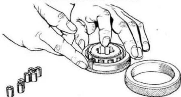
natural_image
Illustration of hands assembling a mechanical component with a ring and multiple cylindrical parts nearby (no text or symbols)Fig.6.34. Assembly of the uni-directional clutch rollers
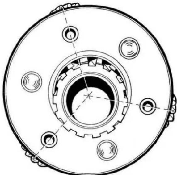
natural_image
Technical line drawing of a mechanical gear assembly with mounting holes and central bore (no text or symbols)Fig.6.35. The marked teeth of the planet carrier gears must be positioned as shown for assembly
0.089 in - 0.090 in (2.25 - 2.28 mm)
0.083 in - 0.084 in (2.10 - 2.13 mm)
0.077 in - 0.078 in (1.95 - 1-98 mm)
10 It is essential that the thrust washers at the front and rear of the sun wheel are fitted in their correct positions. At the front of the wheel the steel washers are fitted next to the head of the support bush in the housing and the bronze washer goes between the steel one and the sun wheel. At the rear, the steel washer fits between the two bronze washers; the bronze washers are similar and it does not matter in which position they go. After replacement of the washer, if applicable, assemble the gear train but do make sure that the planets are turned to their correct relative positions (Fig.6.35).
11 From this point onwards the remainder of the components can be reassembled in the reverse order to that in which they were removed.
19 Overdrive unit, "A" Type Compact - reassembly
1 Fit the operating pistons in the bores making sure that the centre bosses face towards the front of the unit.
2 Press the front bearing into the rear casing and secure with the circlip.
3 Support the inner race of the bearing and then press the annulus into position until the locating shoulder abuts the bearing.
4 Fit the speedometer driving gear.
5 Press the rear bearing on to the tail shaft and into the casing.
6 Press in a new rear oil seal until it is flush with the end of the rear casing.
7 Fit the propeller shaft coupling flange, fit the plain washer and the slotted nut, hold the flange from turning and then tighten the nut to a torque of 1200-1560 lb f in and lock with the split pin.
8 Insert the speedometer pinion gear and bush fitted with a new "O" ring and now turn the annulus to engage the gear and align the holes in the casing and bush. Fit the locating screw and copper washer.
9 Assemble the spring into the roller cage of the unidirectional clutch. Fit the inner member into the cage and engage it with the spring.
10 Engage the slots of the inner member with the torque of the roller cage and check that the spring rotates the cage anticlockwise when viewed from the front.
11 Place the assembly, front end downwards, into an assembly ring made up for the purpose (or use Churchill Tool No. L178) and fit the rollers.
12 Fit the thrust washer and then assemble the unidirectional clutch to enter the rollers into the outer member in the annulus.
13 Fit the oil thrower and its retaining circlip.
14 Turn each planet gear until a dot marked on one tooth of the large gear is positioned radially outwards. THIS IS IMPORTANT. (See Fig.6.35).
15 Now insert the sunwheel to mesh with the planet gears but keep them in the correct position. Fit this assembly to mesh with the internal gear in the annulus.
16 Press the thrust bearing into the thrust ring and then fit them to the hub of the clutch sliding member, but take care not to damage the linings, and secure with the circlip.
17 Now slide the assembly on to the sun wheel splines until the inner lining contacts the annulus and fit the corrugated washer and the circlip.
18 Fit the retaining plate over the studs of the thrust ring bearing assembly.
19 Coat both faces of the brake ring flange with jointing compound and tap the flange home into the front casing.
20 Fit the clutch return springs into the recesses in the front casing and then offer the front casing and brake to the rear casing. Fit the four nuts and tighten them progressively against the clutch spring pressure until the two faces meet.
21 Fit and secure the two bridge pieces with their nuts and lock them with new tab washers.
22 Complete the assembly by fitting the operating valve, the pump valve, the pump and the accumulator piston and spring as described in previous Sections in this Chapter.
20 Overdrive unit - refitting to the gearbox
1 The refitting of both types of unit to the gearbox is generally similar except in the case of the "A" Type Compact unit there are no clutch springs to worry about.
2 You will find that this task is made easier if the overdrive unit is held, upside down, in a vice (with protected jaws).
3 Fit the oil pump operating cam to the gearbox mainshaft so that the plain end faces the gearbox and so that the back of the cam is towards the bottom of the casing.
4 Make sure that the splines in the unidirectional clutch and in the planet carrier are in alignment, you will be able to see these through the bore in the overdrive unit.
5 Engage a gear and then enter the mainshaft into the overdrive unit and turn the constant pinion shaft until the splines engage.
6 Check that the clutch springs are seated on their respective bosses on the gearbox extension. Check that the splines are correctly aligned by pressing down the gearbox until it meets the overdrive unit.
7 Fit the nuts to the long studs and tighten them until there is about 34 " (19.05 mm) gap between the overdrive unit and the gearbox rear extension. Take care during this work that the oil pump cam does not drop down off the splines on the mainshaft.
8 Refer to Fig.6.36. Enter two screwdrivers into the gap and use one of them to compress the oil pump plunger and the other to lever the cam into alignment with the plunger roller.
9 Tighten the two nuts by equal amounts until the other nuts can be started and then tighten down evenly all round.
21 The overdrive control system
The solenoid which actuates the overdrive is controlled by two switches, a manual switch on the facia panel and a switch, mounted on the gearbox cover, which will only close when top gear is selected. So, to enable a change into overdrive to be made:—
a) The car must be in top gear
b) The driver must operate the manual switch
A diagram of the wiring circuit is given in Fig.6.37.

natural_image
Illustration of hands operating a mechanical device with internal components (no text or symbols visible)Fig.6.36. Aligning the cam and the pump plunger roller
22 Overdrive - fault finding
In the event of faults arising in the operation of the overdrive unit, first check the level of oil in the gearbox and, if it is below the low mark, top up and road test the unit before making any further investigation.
If the solenoid is not heard to operate, check the circuit from the diagram at Fig.6.37.
Overdrive does not engage
1 Leaking operating valve due to dirt on the seat or broken valve spring.
2 Pump not working due to choked filter.
3 Leaking pump non-return valve due to dirt on the seating or broken spring.
4 Insufficient hydraulic pressure due to leaks or broken accumulator springs.
5 Damaged gears, bearings or moving parts within the unit which will entail removal and examination of components.
Overdrive does not release
If the overdrive does not release, do not reverse the car, otherwise extensive damage may be caused.
1 Blocked restrictor jet in operating valve.
2 Sticking clutch.
3 Electric control not operating. Listen for operation of sole-noid.
4 Damaged parts within the unit entailing removal and examination of components.

F
Fig.6.37. The overdrive circuit diagram

FIG.6.38. MAIN COMPONENTS OF EXTERNAL CASING WITH TORQUE CONVERTER
1 Torque converter
2 Oil pan
3 Downshift cable
4 Converter housing
5 Stone guard
6 Dipstick tube adaptor
7 Case assembly
8 Rear extension
9 Inhibitor switch
10 Sump drain plug
Inset: Borg Warner Type 35 (assembled)
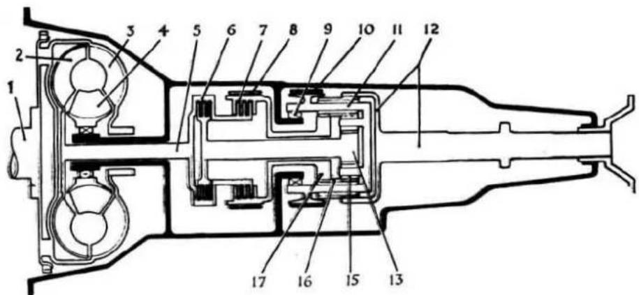
FIG.6.39. SECTIONAL VIEW OF THE MAIN MECHANICAL COMPONENTS
1 Engine crankshaft
2 Turbine
3 Impeller
4 Stator
5 Input shaft
6 Front clutch
7 Rear clutch
8 Front brake band
9 Uni-directional clutch
10 Rear brake band
11 Plant pinion carrier
12 Ring gear and output shaft
13 Forward sun gear and shaft
14 Parking pawl teeth
15 Short planet pinion
16 Long planet pinion
17 Reverse sun gear
Clutch slip in overdrive
1 Insufficient oil in gearbox.
2 Worn clutch lining.
3 Insufficient hydraulic pressure due to leaks.
Freewheel condition on over-run
1 Worn clutch lining.
2 Blocked restrictor jet in operating valve.
3 Insufficient pressure on clutch due to broken clutch springs.
23 Automatic transmission - general description
A Borg Warner Automatic Transmission Unit type "DG" or type 35 on later models, can be supplied as an optional extra. The units consist of a three element hydrokenetic torque converter and a hydraulically operated gearbox comprising a planetary gear set giving three forward gears and reverse. The main components of the unit are shown in Figs. 6.38 and 6.39.
Operation is controlled by positioning a selector lever in one of six positions (five positions on early models): D.1 and D.2 the drive positions - D.1 is used when maximum acceleration below 25 m.p.h. (20 k.p.h.) is required whilst D.2 is used for all normal driving with 2nd gear start.
R - the reverse position
N - neutral
L - to hold gear in which selected
P - park. The engine can be run in this position and when the ignition is switched off the gears are locked.
Gear changes up or down are made automatically and are entirely dependant on road speed but if a rapid change down is required for a sudden burst of acceleration this can be achieved by a "kick-down" change made by fully depressing the accelerator. An anti-creep switch is provided and this prevents the car from creeping forward when stopped on level ground or on a slight slope with the engine running. The anti-creep solenoid holds brake pressure on the rear wheels whenever the circuit is closed; the circuit is opened by a pressure control switch operated by the transmission rear pump.
Due to the complexity of the automatic transmission unit, if the performance is not up to standard or if a fault develops, it is imperative that rectification work is undertaken by a Jaguar dealer who will have the necessary special equipment for fault diagnosis and rectification.
The contents of the following Sections is, therefore, confined to solely general and servicing information.

natural_image
Black-and-white illustration of a hand pouring liquid into a container with a ring and a tube, no visible text or symbolsFig.6.40. Location of the dipstick on early models
24 Automatic transmission - fluid level
It is important that only the correct type of transmission fluid is used. This is S.A.E. Automatic Transmission Fluid type "A" or type "A" Suffix "A" (AQ-TF). The transmission and torque converter oil capacity is 15 imperial pints (18 US pints, 8.5 litres). The fluid level should be checked at regular intervals, and in the manner, as described in Routine Maintenance at the beginning of the Manual.
Access to a combined filler/dipstick plug on early models is obtained by removing the carpet over the transmission cover in the car and then removing a rubber bung to expose the filler plug as shown in Fig. 6.40. On later model cars the filler tube/dipstick will be found forward of the carburettor adjacent to the radiator top water hose and on the latest models it is located at the rear of the engine just forward of the bulkhead.
25 Automatic gearbox - removal and refitting
1 Any suspected faults should be referred to a Jaguar dealer
before any attempt is made to remove the transmission unit as it is necessary to diagnose and to confirm the fault before the unit is disturbed.
2 The automatic gearbox can be removed with the engine installed leaving the converter and housing in position.
3 As the unit is relatively heavy it is best that the car is positioned over a pit or is raised on a lift or a ramp. It is possible to remove the unit if the car is raised on high axle stands but it makes for awkward working. If the car is raised on axle stands, do make sure that it is safely supported before starting work underneath it.
4 Drain the unit but if the car has just come in from a run, wait for it to cool down as the unit operates at a temperature in the region of 100^ C ( 212^ F) and d you will run considerable risk of being scaled.
5 Refer to Chapter 1 and slacken the nuts of the engine stabiliser in the manner described.
6 Slide the front seats as far as possible to the rear and then remove the carpet from the transmission unit cover. Ease up the sound proofing far enough to give access to the screws holding the cover to the body floor. Remove the screws and lift off the cover.
7 Disconnect the downshift cable from the carburettor linkage and the outer cable adjuster from the bracket.
8 Disconnect the battery.
9 Mark the relative positions of the propeller shaft and gearbox flanges. Remove the split pins locking the nuts on the securing bolts, remove the nuts and separate the flanges. Some models may have self locking nuts to the flange securing bolts. Tie the propeller shaft up out of the way.
10 Remove the speedometer drive gear from the extension housing.
11 Identify the position of the cables to the starter inhibitor switch and then disconnect them.
12 Disconnect the selector lever cable from the selector bracket on the side of the gearbox.
13 Sling the engine to take the weight off the rear mounting.
14 Place a wheeled jack in position and take the weight of the gearbox (distribute the weight if the oil pan is used as a jacking point).
15 Refer to Chapter 1 and remove the rear mounting bracket as described.
16 Lower the engine, and gearbox, slightly to give access, on later models, to the hexagonal nut securing the filler tube. Remove the upper retaining clip and then unscrew the tube.
17 Remove the nuts securing the gearbox to the housing starting with the two lower ones.
18 Place a container under the transmission to catch any fluid from the converter when the gearbox is withdrawn.
19 Slide the gearbox rearwards until the mainshaft is clear of the converter. Lower the gearbox and then move it clear of the car.
20 Check to see if the oil transfer tube came away with the mainshaft, it it did not, remove it from the centre of the converter using a pair of long nosed pliers.
21 The first step in refitting is to align the splines on the transmission shaft with the internal splines in the converter. A special alignment fixture, J4283, which uses one of the studs as a datum, is available for this task. In the absence of the fixture you will have to align the splines by eye but do not, under any circumstances, use force during assembly in the hope that this will bring the two items into correct relationship with each other.
22 Fit the oil transfer tube to the mainshaft.
23 Now carry on to refit the gearbox in the reverse order to that in which it was removed from the car, making sure that the gearbox and propeller shaft flanges are assembled to the marks you made before dismantling and that the engine stabiliser is adjusted correctly (see Chapter 1).
26 Torque converter - removal and refitting
1 If diagnosis procedure has established the need for removal of the converter it means that the engine also has to be removed. If desired, the gearbox can first be removed as described in the previous Section, on the other hand it can be left in place and the engine and transmission unit then removed as a complete assembly.
2 Refer to Chapter 1 and follow the procedure described for removal of the engine and gearbox (standard transmission) with the differences, as indicated, to cater for automatic transmission.
3 Wash down the engine and the transmission unit to remove all surface dirt.
4 Remove the gearbox unit in the manner described in Section 25.
5 Remove the starter motor and the earth strap attached to the top bolt.
6 Take off the cover plate from the front face of the converter.
7 Remove the nuts and bolts securing the converter housing to the engine crankcase and withdraw the housing.
8 Take off the six self locking nuts, and washers, which attach the converter to the engine driven plate and withdraw the converter assembly. However, first check for the alignment marks on the converter and the plate. Make your own if necessary.
9 When refitting, the alignment mark "O" on the converter must align with the similar mark on the engine driven plate.
10 Fit the converter to the engine driven plate and screw down the nuts finger tight.
11 The converter must now be centred on the driven plate and this is done by first fitting the housing and the starter motor making sure that the earth strap is fitted to the top bolt.
12 An alignment fixture, J4286, is required to do the job properly. This is entered into the bore of the converter housing and over the pump drive fingers on the converter, and is held in position by the two top gearbox securing nuts. Now rotate the converter through two complete revolutions to centralise it and then fully tighten the nuts securing the converter to the engine driven plate. Take off the fixture.
13 Refit the cover plate to the front face of the housing.
14 Refit the gearbox.
15 Follow the instructions given in Chapter 1 for reinstallation of the engine.
27 Starter inhibitor/reverse light switch - check and adjustment
This switch, besides operating the reverse light, prevents the engine being started when the selector lever is in any position other than N or P.
1 Firmly chock all wheels and apply the handbrake.
2 Make a note of the electrical connections to the switch which is located on the steering column below the upper and lower switch covers, and then disconnect them from the terminals. The starter terminals on most models are the narrow ones and the reverse the wide ones.
3 Connect a test lamp and battery across the starter terminals and then select P, N, D.1, D.2, L and R in turn. The test lamp should only come on in the P and N positions of the selector lever. If it lights in any other position adjust the position of the switch as follows:
4 Refer to Fig. 6.41.
5 Place the selector lever in the "D" position and then slacken the switch securing nut shown arrowed in the drawing.
6 Adjust the position of the switch until the hole in the lever is in line with the hole in the switch base plate. Check for correct alignment by inserting a piece of wire through the holes and then tighten the securing nut.
7 Now recheck with the test lamp as indicated in paragraph 3.
8 The above adjustment should automatically adjust for correct operation of the reverse light. Check this by connecting the test lamp to the reverse terminals and now select P, N, D.1, D.2, L and R in turn. If the switch is correctly adjusted the lamp should light on "R" only.
9 Re-mark the electrical connections to the switch.
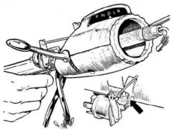
natural_image
Illustration of a hand using a tool to adjust or install a mechanical component, with no visible text or symbols.Fig.6.41. Setting the starter inhibitor/reverse light switch
28 Downshift cable - adjustment
Accurate adjustment of this cable is essential for reliable operation of the transmission. Maladjustment can be identified as follows:-
Outer cable too short - Clutch "squawk" on take off in D or R, or difficulty in obtaining 3-2 kickdown shift at high speed.
Outer cable too long - Delayed and bumpy minimum and part throttle upshifts or a 3-2 downshift at 25 m.p.h. (40 k.p.h.) occurs before the full throttle position (resistance point). Note: The cable is impregnated with silicone grease and there is no need for other lubrication.
1 The adjustment is preset at the factory by means of a cable stop crimped to the inner cable at the carburettor end and this stop should be just clear of the outer cable adjuster.
2 If the indications are that adjustment is necessary, first check that the outer cable at the carburettor end is correctly located in the adjuster.

natural_image
Technical line drawing of a mechanical assembly with no visible text or symbolsCLOSED
THROTTLE

KICKDOWN


natural_image
Simple line drawing of a mechanical device with no text or symbols
Fig.6.42. Position of the downshift valve with the accelerator in the fully released and fully depressed position
3 The most satisfactory method of effecting adjustment is to connect a line pressure gauge to the rear of the transmission unit and to note the change in pressure when the engine is running. This method, of course, requires the use of special equipment and it is better to leave the work to a Jaguar dealer.
4 The cable can also be adjusted to produce manually the conditions shown in Fig. 6.42. First drain off the transmission fluid and then remove the oil sump by taking out the fourteen bolts.
5 With the accelerator pedal fully released and the carburettor butterflies fully closed, the heel of the cam should contact the full diameter of the downshift valve, as illustrated, with all the slack of the inner cable taken up.
6 Now depress the accelerator pedal through the "resistance" point. The carburettors should be at the full throttle stops and the constant radius area of the cam should be in contact with the downshift valve as shown.
7 If the above conditions are not obtained, slacken the locknut on the outer cable adjuster and adjust as necessary.
8 When refitting the oil sump it is advisable to fit a new gasket between the sump and the transmission case.
9 Refill with transmission fluid and road test.
29 Selector linkage - adjustment
1 The components of the selector lever and linkage are shown in Figs. 6.43 and 6.44. Normally, adjustment will only be required if the gearbox or linkage has been removed from the car.
2 First of all, check correct assembly and make sure that the flat on the control shaft is aligned with the securing screw as shown in Fig. 6.45.
3 Disconnect the cable or tie rod, as applicable, at the selector valve lever on the side of the transmission case.
4 For models without both D.1 and D.2 selection, select N on the quadrant in the car.
5 Place the selector valve in the centre of the five possible positions (see Fig. 6.44) and now slacken the locknut at the lower end of the cable and adjust the length of the cable to line up with the hole in the lever.
6 Tighten the locknut and refit the cable to the lever.
7 For those models with D.1 and D.2 selection, make the adjustment of the tie rod with the selector lever in the car in the L position on the quadrant and with the selector valve in its highest position.
8 After adjustment and reconnection, check the operation of the selector by moving it to all positions on the quadrant when a definite "click" should be felt in each position. The linkage must not be allowed to over-ride the detent in each position.
9 Check also that the quadrant gating is correct. N and the D positions on the quadrant should be on the same level, lift for L, R and P and also for disengagement of P.
10 If the indicator does not line up exactly with the lettering on the quadrant, a small amount of adjustment is provided on the nylon block at the back of the indicator arm.
30 Front brake band · adjustment
1 A 0.25 inch (6.35 mm) gauge block (which you can make up out of any suitable material) and a torque screwdriver are needed for this task.
2 Drain off the transmission fluid and then remove the gearbox oil pan.
3 Refer to Fig. 6.46. Slacken the locknut and move the servo lever outwards so that the gauge block can be inserted between the adjusting screw and the servo piston pin.
4 Now tighten the servo adjusting screw, using the torque screwdriver, to a torque of 10 lb f. in. (0.12 kg fm).
5 Hold the screw from turning and then tighten the locknut.
6 Remove the gauge block, refit the oil pan with a new gasket and refill with transmission fluid.

FIG.6.43. EXPLODED VIEW OF THE SELECTOR LEVER ASSEMBLY - TYPE DG UNIT
1 Upper switch cover
2 Lower switch cover
3 Ring dowel
4 Operating shaft assembly
5 Setscrew
6 Nut
7 Plain washer
8 Felt washer
9 Housing
10 Grommet
11 Return spring
12 Distance tube
13 Washer
14 Circlip
15 Shim
16 Selector lever gate
17 Lever assembly
18 Rubber bush
19 Fulcrum pin
20 Screw
21 Indicator arm bracket
22 Connecting link
23 Gear indicator arm
24 Grommet
25 Connecting link for starter/ reverse light inhibitor switch
26 Plain washer
27 Grommet
28 Starter/reverse light inhibitor switch
29 Clip
30 Bell crank connecting link
31 Clevis pin
32 Bell crank control cable lever
33 Support bracket for bell crank lever
34 Securing plate
35 Distance tube
36 Gear selector cable
37 Ball joint
38 Ball joint
39 Steel bush
40 Rubber grommet
41 Clip
42 Abutment clamp
43 Dash panel abutment bracket
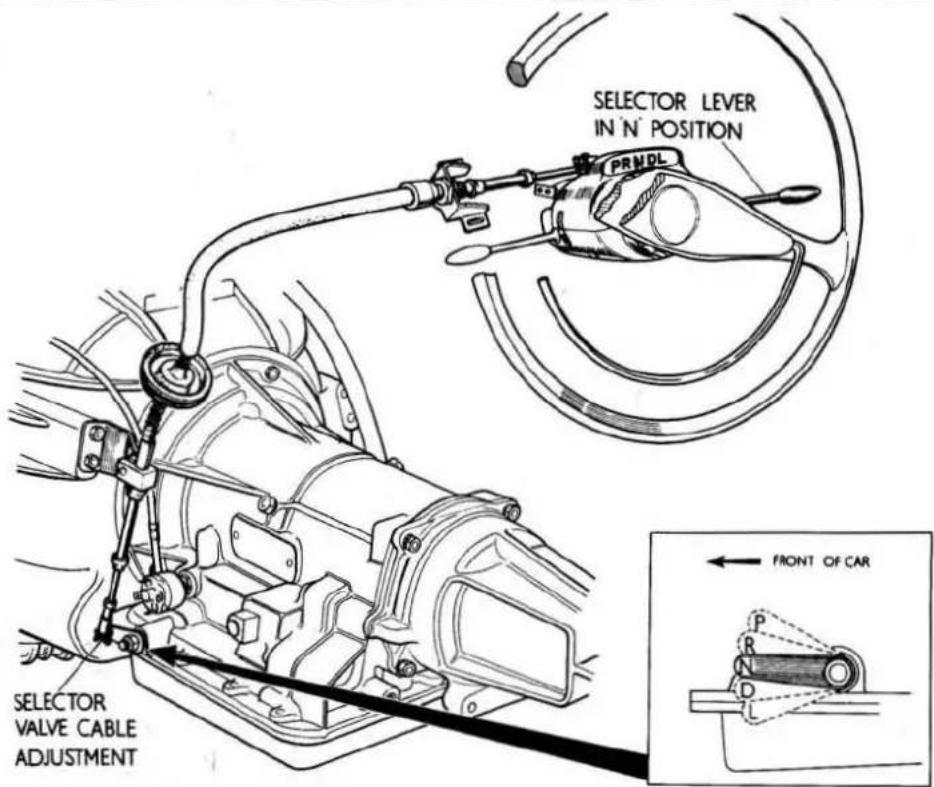
Fig.6.44. The selector lever assembly - type 35 unit
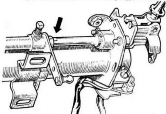
natural_image
Technical line drawing of a mechanical assembly with no visible text or symbolsFig.6.45. Alignment of the flat and the securing screw

natural_image
Silhouette of a person touching a surface with a tool, no visible text or symbolsFig.6.46. Adjusting the front brake band

natural_image
Silhouette of a hand gripping a firearm (no visible text or symbols)Fig.6.47. Adjusting the rear brake band
31 Rear brake band - adjustment
- The rear brake band has an external adjusting screw on the right hand side of the transmission case (Fig. 6.47) and access to it is gained by removing the carpet and felt on the right hand side of the transmission tunnel and then by removing a rubber plug which will be uncovered.
2 Slacken the locknut of the adjusting screw, using a box spanner, and now tighten the adjusting screw to a torque of 10 lb f. ft (1.38 kg fm).
3 Now back off the adjusting screw by one complete turn and, holding the screw from turning, tighten down on the locknut.
4 Refit the rubber plug and replace the felt using a suitable adhesive.
32 Automatic transmission - fault diagnosis
In all cases the following road test procedure should be completely carried out as there may be more than one fault, if the checks show up a fault its possible cause will be found in the Section dealing with road test fault diagnosis. Before carrying out the test procedure, it is important that the car is run long enough for the transmission fluid to attain its normal running temperature and also that the fluid in the unit is at the correct level.
1 Check that the starter will operate only with the selector in the P or N position.
2 Apply the brakes and with the engine at normal idling speed, select N-D, N-L and N-R. Engagement should be felt in each position selected.
3 Check the stall speed as described later in this Section.
4 Select D. Release the brakes and accelerate with minimum throttle opening. Check for 1-2 and 2-3 shifts. These may be difficult to detect so confirmation can be obtained by selecting L, when a 3-2 downshift should be felt.
5 At speeds over 30 m.p.h. (48 k.p.h.) select N, switch off the ignition and coast until the road speed has dropped to 30 m.p.h. Switch on the ignition and select D, the engine should start indicating that the rear oil pump of the transmission is working.
6 From a standing start and using full throttle opening (ie. past the resistance point), check that 1-2 and 2-3 shifts are 39-43 m.p.h. (63-69 k.p.h.) and 58-64 m.p.h. (93-103 k.p.h.) respectively.
7 At 25 m.p.h. (40 k.p.h.) in 3rd gear, depress the accelerator to the resistance point. The car should accelerate in top gear without a downshift.
8 At 30 m.p.h. (40 k.p.h.) in 3rd gear depress the accelerator past the resistance point. The transmission should downshift to 2nd gear.
9 At 40 m.p.h. (64 k.p.h.) in top gear, select L. Check for 3-2 downshift and engine braking. Check for "roll-out" 2-1 downshift and engine braking.
10 Stop with L engaged, release the brakes and using full throttle accelerate to 20 m.p.h. (32 k.p.h.). Check for slip or clutch break-away noise and no upshift.
11 Stop and select R. Release the brake and reverse using full throttle if possible. Check for slip and/or clutch break-away noise.
12 Stop the car on a gradient facing down hill and select P. Release the brakes and check that the parking pawl will hold the car. Repeat with the car facing uphill.
Converter diagnosis
If the general vehicle performance is below standard, check the stall speed as described later.
Inability to start on steep gradients combined with poor acceleration from rest is an indication that the converter stator one-way clutch is slipping or that the stator support is fractured, this will permit the stator to rotate in an opposite direction to the turbine and so prevent torque multiplication. Check the stall speed and if it is more than 650 r.p.m. below normal the
converter assembly must be replaced.
Below standard acceleration in top gear at speeds above 30 m.p.h. (48 k.p.h.) combined with a substantially reduced maximum speed, indicates that the stator one-way clutch has locked in the engaged position. The stator cannot rotate with the turbine and impeller and so the fluid flywheel phase of the converter performance cannot occur. This condition will be associated with severe overheating of the transmission but stall speed will be normal.
A stall speed substantially higher than normal indicates that the converter is not receiving its required fluid supply or that slip is occurring in the clutches of the gearbox. The torque converter is a sealed unit and, therefore, cannot be dismantled, any faults that arise will entail replacement of the complete unit.
Stall speed test
This test provides a rapid check on the correct functioning of the converter as well as the gearbox. The stall speed is the maximum speed at which the engine can drive the torque converter impeller whilst the turbine is held stationary.
As the stall speed is dependant on both engine and torque converter characteristics, it will vary with the condition of the engine and this must be taken into account in order to correctly interpret a low stall speed.
Allow the engine and transmission to attain their normal working temperature, set the handbrake, chock the wheels and apply the footbrake. Start the engine, select L or R and then fully depress the accelerator. Take a quick reading on the revolution counter and release the accelerator.
To avoid overheating, the duration of each stall test must not exceed 10 seconds
| Stall speed engine r.p.m. | Condition |
| 1650 | Normal |
| 1350–1550 | Engine not developing full power |
| Below 1000 | Converter stator free-wheel slipping or stator support fractured |
| Over 1800 | Slip in the gearbox |
Fault diagnosis through road test
The following is a comprehensive list of faults which may be shown up when carrying out the road test procedure; the figures shown opposite each fault are the actions required to cure it and details of these will be found under the heading "Remedial Actions" carry out the actions in the sequence shown. It is appreciated that in many cases you will not have the facilities to do the necessary remedial work, nevertheless they are quoted in order to give you some idea of what rectification entails.
| Fault | Remedial action |
| Starter does not operate in P or N | 19 |
| Starter operates in all positions of selector | 20 |
| Excessive bump when D, L or R are engaged | 4,3 |
| If stall speed higher than specified:- | |
| With slip and break-away noise in L | 1,2,3,13,11 |
| With slip and break-away noise in R | 1,2,3,13,12 |
| If stall speed lower than specified | Check engine performance |
| If stall speed 600 r.p.m. lower than specified | 21 |
| No drive in D | 1,2,3,13,11,16 |
| No drive in D but drive in L normal | 1,2,3,16 |
| No drive in D, L and R | 1,2,3,13,11,17,16 |
| Delayed or no 1-2 shift | 3,14,13,5,6 |
| Slip on 1-2 shift | 2,3,5,6,7,13 |
| Delayed or no 2-3 shift | 3,14,13,5,6,12 |
| Delayed or no 2-3 shift but normal in R | 3,14,13,5,6 |
| Slip or engine run-up on 2-3 shift | 2,3,5,13,12 |
| Bumpy gear shifts | 3 |
| Drag in D.2 and D.3 | 8 |
| Drag or binding on 2-3 shift | 5,6 |
| Engine does not start through rear wheels | 22 |
| Slip, break-away noise or judder on full throttle take off in D | 1,2,3,13,11 |
| Loss of performance and overheating in D.3 | 21 |
| Transmission downshifts too easily | 3 |
| Transmission will not downshift | 3,13,14 |
| No 3-2 downshift or engine braking | 8,9,10 |
| Slip, break-away noise or judder on take off in L | 1,2,3,13,11 |
| Transmission upshifts with L selected | 1 |
| Slip, break-away noise or judder on take off in R | 1,2,3,13,12 |
| Slip but no judder on take off in R | 1,2,3,8,9,10 |
| As above but with engine braking available in L | 1,2,3 |
| Drag in R | 5 |
| No drive in R | 1,2,3,8,13,9,10,12 |
| As above but with engine braking available in 1st gear when L selected | 1,2,3,13,12 |
| Car not held when P selected | 1,15 |
| Screech or whine increasing with engine speed | 17 |
| Grinding and grating noise from gearbox | 18 |
| Knocking noise from torque converter area | 23 |
| D.3 changes to D.2 and immediately back to D3 at high speeds | 12 |
Remedial actions
These actions should be carried out in the order quoted
above.
1 Check adjustment of manual linkage.
2 Check level of transmission fluid.
3 Check adjustment of the downshift cable.
4 Reduce the engine idling speed.
5 Check adjustment of the front band.
6 Check the front servo seals and the fit of the tubes.
7 Check the front band for wear.
8 Check the adjustment of the rear band.
9 Check the rear servo seal and fit of the tubes.
10 Check rear band for wear.
11 Examine the front clutch and seals and also the forward sun gear shaft sealing rings. Check that the cup plug in the driven shaft is not leaking or misplaced.
12 Examine the rear clutch valve and seals. Check fit of the tubes.
13 Strip and clean the valve bodies.
14 Strip and clean the governor valve.
15 Examine the parking pawl, gear and internal linkage.
16 Examine the one-way clutch.
17 Strip and examine the front pump and drive tangs.
18 Strip and examine the gear train.
19 Adjust the starter inhibitor switch inwards.
20 Adjust the starter inhibitor switch outwards.
21 Fit new torque converter.
22 Check the drive pin of the rear pump.
23 Examine the torque converter drive plate for cracks or fractures.
Chapter 7 Propeller shaft and universal joints
Contents
| General description ... ... ... ... ... ... 1 | Centre bearing - refitting ... ... ... ... ... ... 7 |
| Propeller shaft - removal and replacement ... ... ... ... 2 | Sliding joint - dismantling, overhaul and reassembly ... 8 |
| Divided propeller shaft - alignment ... ... ... ... ... 3 | Universal joints - general ... ... ... ... ... ... 9 |
| Centre bearing - general description ... ... ... ... ... 4 | Universal joints - dismantling ... ... ... ... ... ... 10 |
| Centre bearing - dismantling ... ... ... ... ... 5 | Universal joints - reassembly ... ... ... ... ... ... 11 |
| Centre bearing - overhaul ... ... ... ... ... 6 |
Specifications
* With the introduction of the type 4HA rear axle for the 2.4 litre model with effect from the following chassis numbers, the length of the propeller shaft for 2.4 litre cars are identical with those quoted for the 3.4, 3.8, 240 and 340 models.
| RH Drive | LH Drive | |||||||
| Standard transmission ... | ... | ... | ... | ... | ... | 103511 | ) | |
| Overdrive models ... | ... | ... | ... | ... | ... | 103507 | ) | 125693 |
| Automatic transmission models | ... | ... | ... | ... | 103381 | ) | ||
Consequent upon the introduction of the all-synchronesh gearbox, standard transmission cars are fitted with identical propeller shafts to that used on overdrive models with effect from the following chassis numbers
1 General description
Drive is transmitted from the gearbox to the rear axle by means of a finely balanced Hardy Spicer tubular propeller shaft. In the case of standard transmission and overdrive models the shaft is in one piece but for automatic transmission models it is split in two halves and is supported at the centre on a rubber mounted bearing.
Fitted to the front and rear, and at the centre for automatic transmission, are universal joints which allow for vertical movement of the rear axle and for movement of the complete power unit on its rubber mountings. Each universal joint
comprises a four legged centre spider, four needle roller bearings and two yokes.
For and aft movement of the rear axle is catered for by a sliding spline at the front of the propeller shaft assembly which mates with a corresponding splined extension of the gearbox mainshaft.
The yoke flange of the front universal joint is fitted to the gearbox mainshaft flange with four bolts which, in some cases, may be secured with plain washers, nuts and split pins and in others with self locking nuts and plain washers. A similar arrangement is used to secure the rear yoke flange to the pinion flange on the rear axle.

natural_image
Technical line drawing of a mechanical assembly with two views (front and side), no text or symbols present.Fig.7.1. Propeller shaft lengths

FIG.7.2. EXPLODED VIEW OF PROPELLER SHAFT (STANDARD TRANSMISSION)
1 Flange yoke
2 Journal assembly
3 Sleeve yoke assembly
4 Journal spider
5 Gasket
6 Gasket retainer
7 Needle bearing assembly
8 Circlip
9 Grease nipple
10 Bolt
11 Special washer
12 Slotted nut
13 Split pin

natural_image
Technical line drawing of a mechanical assembly with shaft, housing, and mounting flanges (no text or labels)Fig.7.3. Propeller shaft assembly - standard transmission
58

natural_image
Technical line drawing of a mechanical assembly (no text or symbols present)Fig.7.4. Propeller shaft assembly - overdrive model

natural_image
Technical line drawing of a mechanical assembly with shaft, housing, and mounting components (no text or labels)Fig.7.5. Front propeller shaft and centre bearing - automatic transmission

natural_image
Technical line drawing of a mechanical assembly with shafts and housing (no text or labels)Fig.7.6. Rear propeller shaft - automatic transmission
2 Propeller shaft - removal and replacement
1 Place the car over a pit or raise it, preferably on a ramp, to give access to the propeller shaft. If you have to crawl underneath the car do make sure that it is firmly supported, do not trust the jack alone.
2 One of the rear wheels will have to be raised clear of the ground so that the propeller shaft can be turned to bring the yoke securing bolts into an easy position for removal.
3 Mark the propeller shaft and gearbox or rear axle flanges so that the shaft can be reassembled to the car in its original position.
4 For standard transmission models, remove the four nuts and washers from the bolts attaching the shaft to the rear axle flange. Separate the two flanges and withdraw the propeller shaft from the splines at the rear of the gearbox mainshaft.
5 For overdrive models, remove the nuts and washers from the bolts securing the propeller shaft to the gearbox and rear axle flanges. Compress the sliding joint and remove the propeller shaft.
6 A divided propeller shaft is fitted to automatic transmission models. The rear of the front shaft is supported in a ball bearing housed in a rubber mounted plate. Follow the operation in paragraphs 7 - 17 inclusive to remove the front propeller shaft.
7 Remove the six set bolts securing the ventilated cover plate to the bottom of the torque converter housing.
8 Place a piece of wood under the torque converter housing and make sure that it does not foul the torque converter.
9 Jack under the piece of wood to take the weight of the engine and gearbox.
10 Mark the position of the centre bearing and the rear engine mounting brackets relative to the body floor so that they can be put back in their original positions.
11 Remove the six bolts and the packing washers from the rear engine support bracket. Take special care to note the number and positions of the various packing washers fitted between the bracket and the body floor.
12 Remove the two nuts and shakeproof washers attaching the rear engine support bracket to the two mounting rubbers at the rear of the gearbox.
13 Remove the nuts and washers from the bolts securing the shaft and gearbox flanges, leave the bolts in position for the time being to act as a support for the shaft.
14 Mark the rear flange of the front shaft and the front flange of the rear shaft for reassembly in their original position.
15 Make provision for the support of the front end of the rear shaft.
16 Remove the nuts and washers from the bolts securing the flanges of the front and rear shafts.
17 Remove the two set bolts securing the propeller shaft centre bearing bracket to the body of the car and remove the front shaft. Note the number and position of the shims between the bracket and the body of the car.
18 The rear shaft complete may now be removed by undoing the nuts to the bolts securing the rear axle and shaft flanges, remove the bolts and drop the rear propeller shaft. Alternatively, the front universal joint assembly by itself can be removed by disengaging the sliding joint at the front of the rear shaft.
19 Replacement of the propeller shafts for standard transmission and overdrive models is a straightforward reversal of the removal procedure making sure, of course, that the flanges are mated to their reassembly marks.
20 For reassembly of the shafts to automatic transmission models, first offer up the front shaft flange to the gearbox flange and secure with a bolt and nut.
21 Assemble the centre bearing mounting to the body together with the shims in the positions from which they were removed, and secure with the two set bolts and spring washers.
22 Fit the remaining nuts and bolts at the gearbox flange and tighten down.
23 Secure the rear shaft to the rear axle flange with one nut and bolt and offer the sliding joint flange to the front shaft and
secure in position with the four nuts and bolts.
24 Fit the remaining bolts to the rear axle flange and tighten down.
25 Refit the four washers and the two nuts attaching the two rubbers on the rear of the gearbox to the mounting bracket.
26 Place the rear engine mounting in position and refit the set bolts and spring washers with the correct packing washers interposed between the body and the engine rear mounting bracket.
27 Lower the jack from under the converter housing. Replace the cover plate and secure it with the set bolts and spring washers.
28 The alignment of the front and rear shafts must now be checked in case any misalignment has occurred due to disturbing the position of the centre bearing. The alignment must also be checked if the engine has been removed because there is no guarantee that it will go back in exactly the same position as before removal. Misalignment of the propeller shaft will result in transmission judder when taking up the drive from a standing start.
3 Divided propeller shaft alignment
1 Make up a jig to the dimensions shown in Fig.7.7. We made up a jig, using materials ready to hand which did the job admirably. It consisted of a length of wood 3" x 1½" (but any size of wood will do as long as it is not flexible), into the edge of which was knocked three 6" nails, to a depth of about 1", at the spacing shown on the drawing, this meant that the 8" vertical dimension was undersize but clearance proved to be adequate. The nails were checked for vertical alignment and then a straight edge was placed along the heads to make sure that they were aligned in the horizontal plane.
2 Disconnect the engine stabiliser by unscrewing the self locking nut clear of the mounting bracket and then screw down the lower washer until it also is clear of the bracket.
3 Check that the rear engine mounting rubbers are not distorted, rectify if necessary by adjusting in the slotted holes in the rear engine mounting cradle.
4 Refer to Fig.7.8.
5 Offer up the jig to the propeller shaft in the manner shown; for the 3.8 litre model the clearance between the second leg of the jig and the rear of the front shaft should be 9/64'' (3.6 mm). There would be no clearance on all other models, each leg of the jig should bear evenly on the shaft.
6 Misalignment can be corrected by aiding or subtracting shims between the centre bearing bracket mounting and the body. (See Fig.7.9).
7 Now check that the shafts are in a straight line fore and aft. Place the legs of the jig on the side of the shaft (Fig.7.10), each leg should bear evenly but do make sure, if you use the home made jig described above, that the nails are indeed correctly aligned. As an alternative, drop three plumb bobs, two from the front and one from the rear shaft and sight along the cords.
8 Misalignment in this plane can be corrected by elongating the two holes through which the set screws pass to secure the bracket to the body floor and then adjust the position of the centre bearing bracket as necessary.
9 When satisfied with the alignment of the propeller shafts, adjust the engine stabiliser by screwing the lower flanged washer up the stabiliser pin until the flange contacts the bottom of the rubber mounting. The washer is slotted on its upper face and if it is tight it can be screwed up the pin by engaging a thin bladed screwdriver through the centre hole of the rubber mounting. Now tighten down on the upper flanged washer with the self-locking nut.
4 Centre bearing - general description
The centre bearing consists of a ball bearing race pressed into a housing having an oval plate attached. The assembly is mounted at the rear of the front propeller shaft by a flange
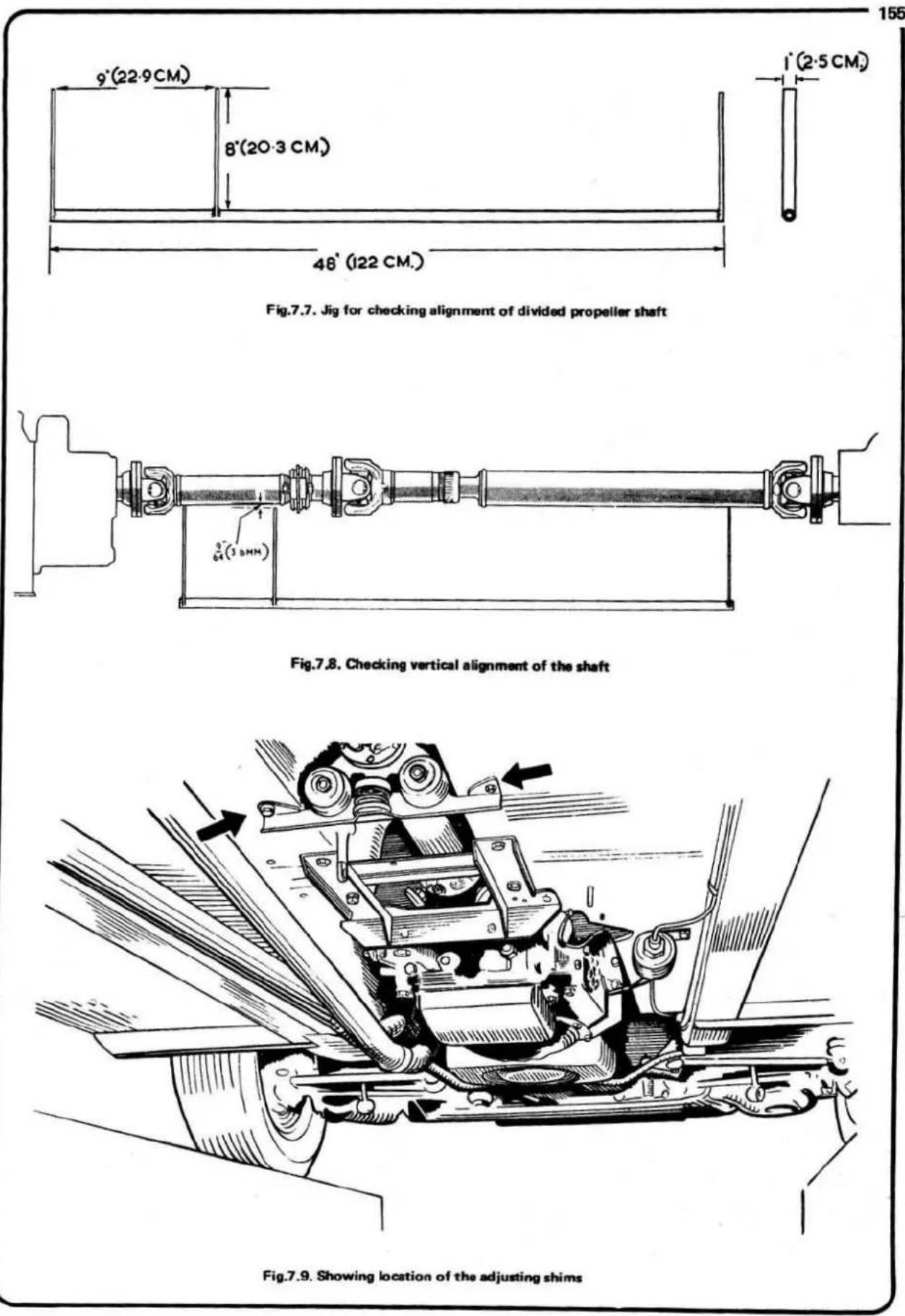

natural_image
Technical illustration of a mechanical assembly with hands operating a lever (no text or symbols present)Fig.7.10. Checking horizontal alignment of the shaft
coupling which bolts to the mating flange on the rear shaft. A dust shield is interposed between the housing and the shaft tubing to give protection.
5 Centre bearing - dismantling
1 Remove the front propeller shaft as described in Section 2.
2 The flange coupling is secured on the shaft by a slotted nut and split pin and is retained by two Woodruff keys.
3 Remove the split pin and the slotted nut. Drive the flange coupling off the taper of the shaft and collect the Woodruff keys.
4 Remove the dust shield.
5 Drive the shaft through the bearing and housing and press the bearing out of the housing, and collect the front dust shield.
6 Separate the body mounting from the rubbers by removing the two nuts and spring washers.
7 Press the rubbers out of the oval bearer plate and remove the rubbers from the studs.
6 Centre bearing - overhaul
1 Examine the ball race. Make sure there is no play in the outer cage and clean and re-lubricate with grease as necessary.
2 Check that the rubbers are not perished, renew as necessary.
7 Centre bearing - refitting
1 Refitting is the reverse to the dismantling procedure given in Section 5.
2 The front propeller shaft is refitted to the car as outlined in Section 2 after which the alignment of the shafts must be checked in the manner described in Section 3.
8 Sliding joint - dismantling, overhaul and reassembly
1 Refer to Section 2 and remove the propeller shaft assembly or, in the case of automatic transmission, remove the rear half of the propeller shaft.
2 Where appropriate, roll back the rubber rings attaching the gaiter to the shaft and then slide off the sleeve yoke assembly.
3 Remove the gaiter from the sleeve yoke by detaching the steel ring and then slide the gaiter off the yoke.
4 Your car may be an older model fitted with a knurled dust cap instead of a rubber gaiter. Unscrew the cap to separate the sleeve yoke assembly.
5 The male and female splines can now be cleaned as may be necessary to allow close examination.
6 Check that the shaft and yoke assembly slide freely together, investigate any sign of stiffness which may be due to tightness in the splines resulting from burring, rectify as may be required but be careful not to reduce the overall width of the spline or splines.
7 Visually examine the splines for wear and if they appear to be satisfactory, assemble the yoke to the shaft and check that there is no rotary movement in excess of 0.004" (0.1 mm) between the two items. If there is any wear it will be necessary to replace the assembly.
8 Reassembly is the reverse of the dismantling procedure. However, first grease the splines and then assemble the sleeve yoke on the splines so that the fixed yoke is aligned with the fixed yoke on the shaft, arrows are stamped on the two parts to facilitate alignment (see Fig.7.16).
9 Universal joints - general
1 Wear in the needle roller bearings is characterised by judder and vibration in the transmission on over-run, 'clonks' on taking up the drive, and in extreme cases of lack of lubrication, metallic squeaking and ultimately grating and shrieking sounds as the bearings break up.
2 It is easy to check if the needle roller bearings are worn; with the propeller shaft in position, try to turn the shaft with one hand and with the other hand hold the rear axle flange and repeat this procedure for the other joints. Any movement between the shaft and the front, centre or rear couplings is indicative of bearing failure and/or wear in the spider. The old bearings will have to be discarded and replaced by a new universal joint assembly.
10 Universal joints - dismantling
1 Remove the propeller shaft, or that part of the shaft applicable in the case of a divided shaft, in the manner described in Section 2.
2 Thoroughly clean all dirt from the rings and the top of the bearing surfaces.
3 Remove all the snap rings by pinching with a pair of pliers and at the same time arising out with a screwdriver. If a ring proves difficult to remove it may be because it is jammed by the end of the bearing race so lightly tap the end of the race to relieve the pressure.
4 Hold the joint in the hand and with a hide faced or other type of soft hammer, tap the yoke lug as shown in Fig.7.11. This will cause the top bearing to work outwards until it can finally be removed with the fingers (Fig. 7.12). If the top bearing proves obstinate it can be tapped out from inside (Fig.7.13) with a small diameter punch or piece of bar but be careful you do not damage the bearing if this is not being replaced.
5 Repeat the above procedure for the opposite bearing.
6 The splined sleeve yoke or flange can now be separated from the shaft yoke as depicted in Fig.7.14.
7 Rest the two trunnions which are now exposed, on wood blocks and tap the yoke with a soft nosed hammer to remove the two remaining races.
8 It is now advisable to look carefully at the yoke cross holes. It is a very rare event but these holes have been known to wear to a certain degree of ovality. If this has occurred the defective item will have to be replaced and if it is a fixed yoke on a shaft the complete assembly will have to be renewed.

natural_image
Illustration of a hand using a hammer to tighten a small mechanical component (no text or symbols present)Fig.7.11. Removing a universal joint bearing

natural_image
Illustration of hands using a hammer to adjust a mechanical component (no text or symbols present)Fig.7.13. Tapping out a bearing

natural_image
Illustration of two hands adjusting a mechanical component, one with a flange and the other with a bolt (no text or symbols present)Fig.7.12. Withdraw the bearing

natural_image
Illustration of two hands holding a mechanical device (no text or symbols visible)Fig.7.14. Separating the yokes
11 Universal joint - reassembly
the bearings and snap rings in the same manner as described above. It is essential that the sliding joint is refitted with its fixed yoke in line with the fixed yoke at the end of the propeller shaft; arrows are stamped on the two items to facilitate alignment (see Fig.7.16).
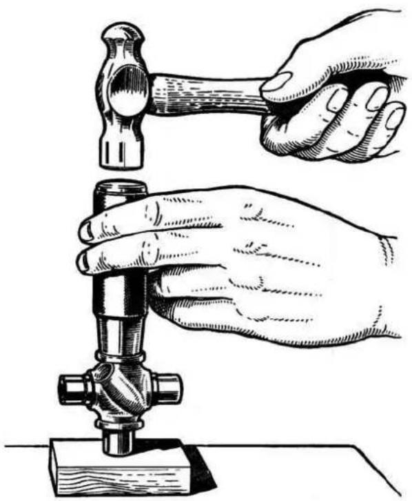
natural_image
Illustration of a hand using a hammer to press a mechanical component (no text or symbols present)Fig.7.15. Replacing a gasket retainer
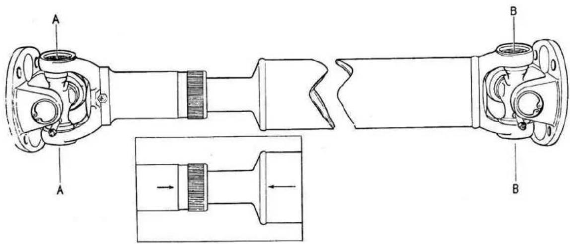
Fig.7.16. Alignment of yokes
A and B fixed yoke must be in the same plane
Chapter 8 Rear axle
Contents
| General description | ... | ... | ... | ... | ... | ... | 1 |
| Rear axle - removal and replacement | ... | ... | ... | ... | ... | ... | 2 |
| Rear axle - dismantling for replacement | ... | ... | ... | ... | ... | ... | 3 |
| Axle shaft, bearing and oil seal - removal and replacement | ... | ... | ... | ... | ... | ... | 4 |
| Pinion oil seal - removal and replacement | ... | ... | ... | ... | ... | ... | 5 |
| Differential assembly (conventional and Thornton "Powr-Lok) - removal | ... | ... | ... | ... | ... | ... | 6 |
| Pinion - removal | ... | ... | ... | ... | ... | ... | 7 |
| Differential assembly, conventional type - dismantling | 8 |
| Differential assembly, Thornton "Powr-Lok" - dismantling | 9 |
| Differential unit, conventional type - reassembly, adjustment and refitting | 10 |
| Differential unit Thornton "Powr-Lok" - reassembly, adjustment and refitting | 11 |
Specifications
Axle shaft endfloat
| Drum brake cars | ... | ... | ... | ... | ... | ... | ... | 0.006 to 0.008 in. (0.15 to 0.20 mm) |
| Disc brake cars | ... | ... | ... | ... | ... | ... | ... | 0.003 to 0.005 in. (0.08 to 0.13 mm) |
| Differential bearing preload | ... | ... | ... | ... | ... | ... | 0.005 in. (0.13 mm) shim allowance | |
| Pinion bearing preload | ... | ... | ... | ... | ... | ... | ... | .8 to 12 lbs f in. (0.09 to 0.14 kg f m) |
| Backlash | ... | ... | ... | ... | ... | ... | ... | As etched on drive gear - minimum 0.004 in. (0.10 mm) |
Lubricant capacity
| 2.4 litre Mk 1 and early Mk 2 with type 3HA axle | ... | ... | 214 | 234 | 1.3 |
| All other models fitted with type 4HA axle | ... | ... | 214 | 314 | 1.6 |
Torque wrench settings
| Drive gear bolts: | ||||||
| 3/8 in. (9.5 mm) diameter bolts ... | ... | ... | ... | ... | ... | 50 to 60 lbs f ft (6.9 to 8.3 kg f m) |
| 7/16 in. (11.1 mm) diameter bolts | ... | ... | ... | ... | ... | 70 to 80 lbs f ft (9.7 to 11.1 kg f m) |
| Differential bearing cap bolts ... | ... | ... | ... | ... | ... | 60 to 65 lbs f ft (9.3 to 9.0 kg f m) |
| Pinion nut ... | ... | ... | ... | ... | ... | 120 to 130 lbs f ft (16.6 to 18.0 kg f m) |
| Thornton "Powr-Lok" differential bolts ... | ... | ... | ... | ... | ... | 35 to 45 lbs f ft (4.8 to 6.2 kg f m) |
Special tools
The following special tools are required for the efficient overhaul of the axle, alternatives, where suitable, are suggested in the text of this Chapter, but your attention is drawn to the note at the end of this Section.
| Tool | Churchill tool number | ||||||
| Axle shaft extractor ... ... ... ... ... ... ... SL.13 | |||||||
| Pinion and differential bearing cone puller ... ... ... ... SL.14 with SL.14-1 | |||||||
| Gear carrier stretching fixture ... ... ... ... ... S1.1 | |||||||
| Pinion bearing cup extractor ... ... ... ... ... ) SL.550-4 with 550 handle | |||||||
| Bearing cup installation tool ... ... ... ... ... ) | |||||||
| Pinion cone setting gauge ... ... ... ... ... ... SL.3 | |||||||
| Pinion oil seal installation collar ... ... ... ... SL.4 | |||||||
| Rear hub extractor (for disc wheel hubs) ... ... ... JD.1 | |||||||
| Rear hub extractor (for wire wheel hubs) ... ... ... JD.7 | |||||||
| Multi-purpose hand press ... ... ... ... ... SL.14 | |||||||
Note
Full servicing instructions for the rear axle are given in this Chapter but in view of the intricate adjustments and the number of special tools required, we advise that you take advantage of the factory reconditioning scheme and obtain a replacement axle on an exchange basis, if the need arises.
1 General description
All models are fitted with a Salisbury axle, early 2.4 litre cars were equipped with the 3.HA type whilst all other models have the 4.HA type. Both types are basically similar. The rear axle assembly, illustrated in Fig. 8.1 is of the semi-floating type with shim adjustment for all bearings and meshing of the hypoid crown wheel and pinion matched assembly. The axle shafts are splined at their inner ends and engage with splines in the differential side gears whilst the outer ends have tapers to fit the rear wheel hubs to which they are keyed. The hubs are supported on taper roller bearings which are pressed to the axle shafts and located in the ends of the axle tubes. Outward thrust on the wheels is taken by the adjacent hub bearing, inward thrust is transmitted through the axle shafts and slotted axle shaft spacer to the opposite bearing. The 3.8 litre car is fitted with a Thornton "Powr-Lok" differential as standard equipment (optional extra for North America) and is supplied to special order for the 2.4 litre Mk.2 and the 240 model. Cars fitted with this item have a metal tag stamped P/L attached by a rear cover axle bolt. If a tag is not fitted, remove the filler plug and if the differential case can be seen close to the filler hole it can be assumed that a Thornton differential is fitted.
The Thornton "Powr-Lok" differential, an exploded view of which is given in Fig.8.2, is a limited slip differential which differs from the conventional type in that on slippery surfaces it will not allow the wheel with the lesser traction to spin, gain momentum and swerve the car when a dry surface is regained. In turns, the differential applies the major driving force to the inside rear wheel thus improving stability and cornering and under conditions of poor traction it enables the wheel with the better traction to apply the major driving force to the road. Bumps do not adversely affect wheel action when the wheels are controlled by a limited slip differential as the free wheel does not spin and gain momentum and thus there is no sudden wheel stoppage to cause tyre scuffing or to cause the car to swerve.
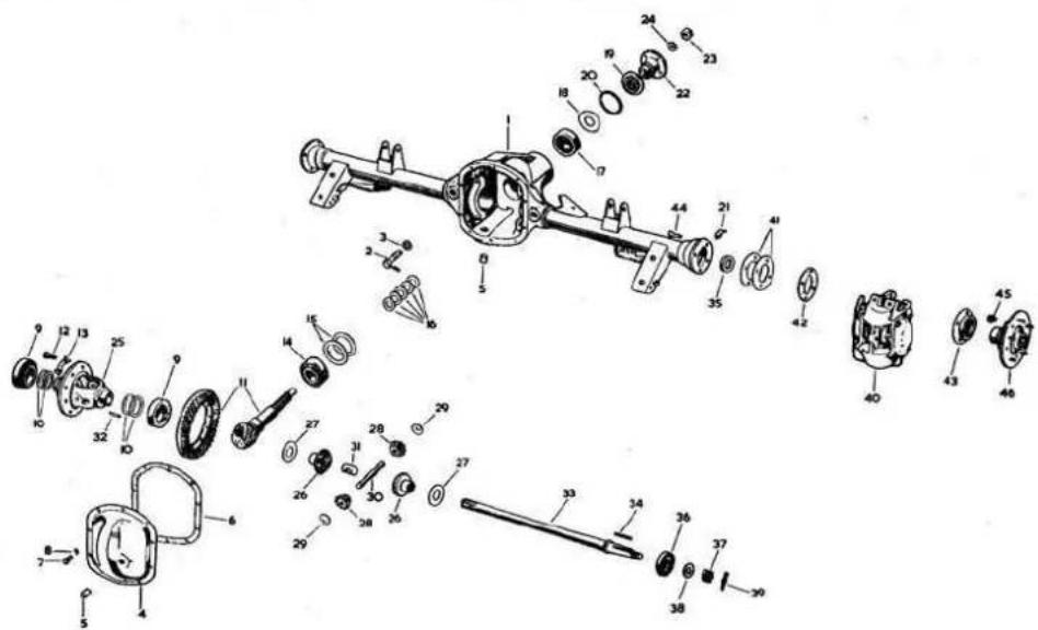
FIG.8.1. EXPLODED VIEW OF THE REAR AXLE (DISC BRAKES)
1 Carrier and tube assembly
2 Setscrew
3 Shakeproof washer
4 Rear cover
5 Drain and filler plug
6 Gasket
7 Setscrew
8 Lockwasher
9 Roller bearing
10 Shim
11 Drive gear and pinion
12 Setscrew
13 Lock strap
14 Roller bearing
15 Shim (inner)
16 Shim (outer)
17 Roller bearing
18 Oil slinger
19 Oil seal
20 Gasket
21 Grease nipple
22 Universal joint flange
23 Nut
24 Washer
25 Differential case
26 Side gear
27 Thrust washer
28 Differential pinion mate
gear
29 Thrust washer
30 Pinion mate gear shaft
31 Spacer
32 Pinion mate shaft lock
pin
33 Axle shaft
34 Key
35 Oil seal
36 Taper roller bearing
37 Slotted nut
38 Washer
39 Split pin
40 Rear brake assembly
41 Shim
42 Gasket
43 Retainer
44 Bolt
45 Self-locking bolt
46 Rear hub

FIG.8.2. EXPLODED VIEW OF THE THORNTON 'POWR-LOK'
1 Differential casing - flange half
2 Dished clutch friction plate
3 Clutch friction disc
4 Clutch friction plate
5 Side gear ring
6 Bevel side gear
7 Bevel pinion mate gear assembly
8 Differential case - button half
9 Differential case - screw
10 Pinion mate cross shaft.
11 Axle shaft spacer roll pin
12 Axle shaft spacer
Because of this, the engine of a car fitted with a Thornton "Powr-Lok" differential must never be run with the car in gear and with one wheel jacked up off the ground otherwise, owing to the action of the differential, the car may drive itself off the jack or stand. If it is desired to run the transmission with the car stationary, both wheels must be jacked up clear of the ground.
2 Rear axle - removal and replacement
1 Chock the front wheels, jack up the car under the rear axle and place substantial blocks at a strong point under the chassis forward of the road spring front mounting.
2 Remove the rear road wheel cover assembly and remove the wheels.
3 Remove the axle drain plug and drain the oil.
4 Release the handbrake. Remove the split pin and plain washer of the clevis pin attaching the handbrake primary cable to the compensator assembly on the rear axle. Remove the clevis pin and detach the cable.
5 Undo the union of the rigid brake hydraulic pipe attaching it to the flexible pipe at the bracket at the right hand side of the body. Allow the fluid to syphon out into a clean container and then tie a piece of rag around the nut and the end of the pipe to prevent ingress of dirt.
6 Hold the nut attached to the flexible pipe at the bracket. Slacken the locknut and remove it, holding the pipe all the time to prevent it turning. Withdraw the pipe from the bracket and tie a piece of rag around the end to prevent the ingress of dirt.
7 Remove the nuts and bolts securing the rear axle pinion flange to the flange of the propeller shaft. Push the shaft forward on its sliding joint away from the pinion flange. Tie the shaft up out of the way at any convenient position on the underbody of the car.
8 Remove the two nuts, the inner and outer washers and the rubber buffers from the damper attachment bracket on the rear axle. Compress the hydraulic damper clear of the axle.
9 Release the torque arm by removing the self locking nuts from the bolts securing the arms to the axle, take off the plain washers and drift out the bolts. To prevent damaging the thread of the bolt, if they prove to be tight it is advisable to have the nut in position to protect the end of the bolt when drifting it out, partially unscrewing the nut as the bolt moves out and then finally finish knocking out the bolt with a punch on its centre. 10 Remove the nuts securing the panhard rod to the axle and withdraw the rubber buffers and washers.
11 A decision must now be made concerning the manner in which you propose to remove the axle. You can either disconnect the exhaust tail pipe(s) at the rear bracket and undo the clamps attaching the pipe(s) to the silencers and remove the tail pipe assembly so that the axle can be dropped straight down after final disconnection. Or you can disconnect the tail pipe(s) at the rear bracket, remove the nuts and bolts attaching the silencers to their brackets on the body and then allow the exhaust assembly to drop down as may be allowed by the flexible section at the front of the pipes but support the pipes so that too much strain is not put on the flexible joints. Use of the latter method means working the axle towards the rear of the car and over the top of the exhaust tail pipes.
12 Lower the axle as far as possible on the jack.
13 Remove the nuts securing the road springs eyebolts and drift out the bolts using the same precautions as advised in paragraph 9 to avoid damage to the thread.
14 The rear axle is now completely disconnected from the car and may either be lowered to the floor or worked out to the rear of the car as applicable.
15 Replacing the rear axle is the reverse of the above procedure but it will be necessary to bleed the brake system as described in Chapter 9 and to check the setting of the panhard rod according to the instructions given in Chapter 11. Not forgetting to replenish the axle with one of the recommended lubricants.
3 Rear axle - dismantling for replacement
Reconditioned axles supplied on an exchange basis are complete less hubs and brake assemblies so these items must be removed before the item is returned.
1 Take out the split pins and remove the clevis pins attaching the handbrake cables to the brake assembly.
2 Remove the two setscrews attaching the handbrake compensator bracket to the rear axle and remove the compensator with the right and left hand brake cables attached.
3 Clean all dirt from the hydraulic pipe unions to the right and left hand brake assembly. Undo the unions and cover the end of the pipes with rag to prevent the ingress of dirt and also plug the connections at the brake cylinders.
4 Remove the nut and bolt securing the 3-way adaptor to the rear axle and remove the adaptor with the two rigid pipes and the flexible pipe attached. Remove the brake pipe clips from the axle.
5 Remove the brake assemblies as described in Chapter 9.
6 Withdraw the split pin and remove the slotted nut securing each hub to the axle shaft.
7 Remove each hub using a suitable extractor, Fig.8.3, (see list of tools under Specifications). It is known that the hub may prove to be extremely difficult to remove and if you cannot shift it with the tools available to you we suggest that you seek expert help.
8 Detach the brake caliper mounting plate from the end of the axle tube by removing the four nuts and bolts.
9 Lift out the key on the axle shaft and store in a safe place.
10 Replacement of items on the new axle is the reverse of the above.

natural_image
Technical line drawing of a mechanical assembly with a conical component and shaft (no text or symbols)Fig.8.3. Withdrawing the rear hub
4 Axle shaft, bearing and oil seal - removal and replacement
1 Apply the handbrake, chock the front wheels, jack up the rear of the car and take the weight on firmly based axle stands.
2 Remove the rear road wheel cover assembly and remove the wheel.
3 Remove the clevis pin securing the handbrake cable to the brake operating lever.
4 Clean all dirt from the area of the brake hydraulic pipe unions. Disconnect the hydraulic pipes and blank off all unions to prevent the ingress of dirt.
5 Remove the handbrake and foot brake caliper assemblies (disc brakes) or the brake drum, brake shoes and cylinder assembly for those cars with drum brakes, as described in Chapter 9.
6 Remove the split pin and the slotted nut securing the rear hub.
7 Withdraw the hub from the axle shaft using a suitable extractor. (But see Section 3 para.7).
8 For those cars fitted with drum brakes, remove the four nuts and bolts securing the back plate to the end of the axle tube and withdraw the back plate. Note the bearing retainer plate, two gaskets and the oil seal at the front of the backplate and the shims fitted between the back plate and the flange of the axle tube. Do not lose or transpose these shims if the other end of the axle is being worked on, as they control the end float of the axle shaft.
9 For disc brake models, remove the four nuts and bolts securing the brake caliper mounting plate to the end of the axle tube, remove the plate and the oil seal retainer and preserve any shims which may be fitted between the mounting bracket and the axle tube.
10 Remove the key from the axle shaft and put it in a safe place. 11 Withdraw the axle shaft with its taper roller bearing from the end of the axle tube using tool number SL.13 (see special tools under Specification) as illustrated in Fig.8.4. An alternative method of removing the axle shaft is to fit the retaining nut, grip the nut with a mole wrench and pull outwards. If the axle proves stubborn, it can usually be started to move by tapping on the wrench but make sure you do not load the bearing unduly.
12 If a replacement hub bearing is required, withdraw the inner race from the axle shaft using tool number SL.14 with SL.14-1. Alternatively, the bearing may be removed from the shaft by placing the bearing on the top of the jaws of a vice, fit the axle shaft nut to protect the thread and then drive the shaft through the race using a soft faced hammer.
13 Examine the oil seal which is pressed inside the axle tube, if it appears to be satisfactory and no trouble has been experienced with oil leaks, leave it in position as once the seal has been removed it must be replaced with a new item. The seal can be removed by using a piece of metal bar shaped in the form of a hook. Pull on the seal and draw it from the axle tube.
14 Refitting is the reverse of the above procedure, but in addition, the following operations must be carried out.
15 Wash the bearing in clean paraffin to remove all grease. Clean
all grease from the bearing retainer, the shims and the face of the axle tube.
16 Assemble the new oil seal, if applicable, and make sure it is bedded down properly.
17 Assemble the bearing to the axle shaft keeping it square on the shaft, push it on to the shaft as far as possible by hand and then, with a piece of tube of suitable diameter against the inner cage, tap it home gently until it is bearing hard against the shoulder on the shaft.
18 Enter the shaft in the axle tube taking care not to damage the oil seal. Taking the weight of the shaft, push it home and rotate in either direction to engage the splines in the differential.
19 Examine the retainer gasket and if there is any doubt as to its condition, fit a new one. We advise that a new item should be fitted as a matter of course.
20 Fit the bolts to the retainer and then place the gasket in position over them followed by the shims. You will find it easier to assemble the retainer in this manner rather than try to line up the thin and flimsy shims with the bolts. Assemble the retainer to the axle tube and tighten down.
21 The end float of the axle shaft must now be checked and this should be 0.006" to 0.008" (0.15 to 0.20 mm) for those cars equipped with drum brakes and 0.003" to 0.005" (0.08 to 0.13 mm) for disc brake models. It will be appreciated that this amount of movement is hardly perceptible by hand and so the only satisfactory method of checking the movement is to use a Dial Test Indicator either clamped to the axle tube as illustrated in Fig.8.5 or attached to it by a magnetic base. Set the indicator to give a reading on the end of the shaft and then move the shaft inwards and outwards and record the range of movement.
22 Add or subtract adjusting shims, which are available in thicknesses of 0.003", 0.005", 0.010" and 0.030" (0.08, 0.13, 0.25 and 0.76 mm), until the correct end float is obtained. Adding shims increases and subtracting decreases, the float, the aim should be to install approximately an equal thickness of shims at each axle shaft in order to maintain the spacer in a central position.
23 When adjustment of the end float is complete, grease the hub bearings via the grease nipple with the recommended lubricant until the grease exudes from the bleed hole.
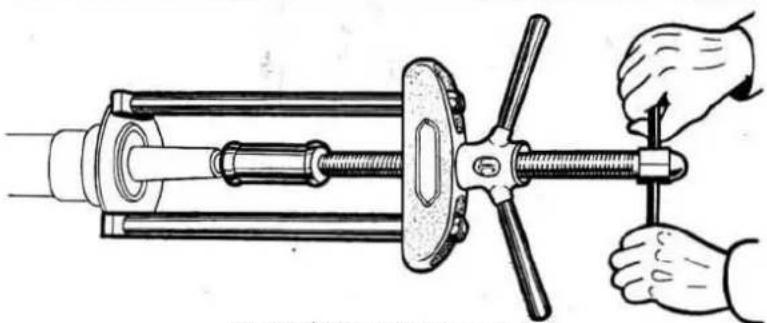
natural_image
Illustration of a mechanical clamp or tool being adjusted with hands, no text or symbols presentFig.8.4. Withdrawing the axle shaft

natural_image
Illustration of a hand using a mechanical tool to adjust or install a component (no text or symbols visible)Fig.8.5. Checking end float of the axle shaft
5 Pinion oil seal - removal and replacement
1 Apply the handbrake, chock the front wheels, jack up the rear of the car and support on firmly based axle stands.
2 Mark the relative positions of the pinion and propeller shaft flanges for reassembly in their original position.
3 Remove the four nuts and bolts securing the flanges, push the propeller shaft forward on its sliding spline to disengage the flanges. Tie the propeller shaft up to the underbody out of the way.
4 Make sure that the handbrake is really firmly applied.
5 Remove the split pin locking the nut securing the pinion flange. Remove the nut and plain washer.
6 Place a container under the pinion end of the rear axle to catch any oil which may escape when the pinion flange and oil seal underneath it are removed.
7 Using a universal puller and thrust block, draw the flange off the pinion.
8 The old oil seal may now be prised out using a screwdriver or a thin piece of metal bent into a hook.
9 Fitting the new oil seal and final reassembly is the reverse of the above procedure but the following additional points should be noted.
10 Place the oil seal with the dust excluder flangeuppermost (not forgetting the oil seal gasket used with the metal cased type seal used on later models) in position. Fit the installation collar, Tool number SL.4, fit the pinion nut and washer and then tighten down on the nut to drive the assembly home as illustrated in Fig.8.6. Remove the nut and washer and the installation collar.
11 Now fit the pinion flange making sure it enters the splines correctly, assemble the plain washer and screw on the nut to a torque of 120 to 130 lbs ft (16.6 to 18 kg f m).
5 It is now necessary to cancel out the differential preload and for this a stretching fixture, Tool No: SL.1, is available. Adjust the fixture to suit the model being worked on and then fit it to the casing as shown in Fig.8.7, open the fixture by means of the turnbuckle until it is hand tight and then use a spanner to take it up a further half turn only, do not exceed this amount otherwise the axle casing will be damaged. The differential assembly may now be prised out using a lever on each side of the differential case opening but use packing between the levers and the gear carrier to prevent damage to the carrier. If a stretching fixture is not available, you will find it possible, although a little more difficult, to prise out the assembly using the levers only but take care not to tilt the assembly and do wedge it more tightly than it is held by the preload.
7 Pinion - removal
1 Take out the split pin locking the pinion nut, remove the nut and the plain washer.
2 Withdraw the propeller shaft companion flange using a suitable puller.
3 Remove the differential assembly as described in Section 6.
4 Press the pinion out of the outer bearing and remove from the gear carrier housing, collect all shims (and the distance washer) and keep them intact as a set. The pinion must not be driven out as this will damage the outer bearing.
5 The pinion oil seal may now be removed together with the oil slinger and the outer bearing cone.
6 If the outer bearing is to be replaced it may be driven out and this also applies to the inner bearing but watch for the pinion adjustment shims fitted between that bearing and the housing abutment face. However, if the inner bearing is to be removed to

natural_image
Illustration of hands using a wrench to adjust a mechanical component (no text or symbols present)Fig.8.6. Fitting the pinion oil seal
6 Differential assembly (conventional and Thornton "Powr-Lok") - removal
1 Before stripping an axle fitted with a Thornton "Powr-Lok" differential carry out a check for wear in the assembly. With one axle shaft and the pinion locked, the other axle shaft should not turn radially more than 34 (19 mm) measured on a 6" (152 mm) radius.
2 Remove the rear axle from the car and remove the axle shafts as described in Sections 2 and 4.
3 Take out the ten setscrews, with their spring washers, securing the gear carrier cover and remove the cover and its gasket.
4 Take out the bolts securing the differential caps and remove the two caps after marking them, if necessary, for reassembly to their original positions.
allow adjustment of the pinion there is no alternative to the use of the correct tool for its removal and installation (Fig.8.8 and 8.9) see list of tools under Specifications).
8 Differential assembly, conventional type - dismantling
1 Refer to Fig.8.10.
2 Tap down the tabs of the locking straps to the crown wheel setscrews and remove the screws and the locking straps.
3 Tap the crown wheel off the differential case using a hide faced hammer.
4 Drive out the pinion mate shaft locking pin. This pin is secured by peening to the case and can only be driven out in one direction as illustrated in Fig.8.11.
5 Remove the axle shaft spacer.
6. Turn the side gears by hand to bring the pinions opposite to
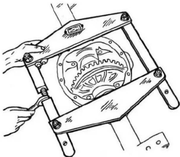
natural_image
Technical line drawing of a mechanical device with gears and mounting brackets (no text or symbols)Fig.8.7. Stretching the gear carrier
the openings in the differential case and then remove the differential gears. Be careful not to lose the thrust washers fitted behind the gears.
7 If the setting of the crown wheel is to be adjusted it will be necessary to take out the differential bearings using Tool No: SL.14 and SL.14-1 (see Fig.8.12) in order to get at the shims which are located between the bearing and their mating face on the differential case.

natural_image
Illustration of a mechanical press or measuring device with hands operating it (no text or symbols visible)Fig.8.8. Withdrawing the pinion inner bearing

natural_image
Illustration of hands using a tool to adjust or install a mechanical component (no text or symbols visible)Fig.8.9. Removing the pinion inner bearing cup
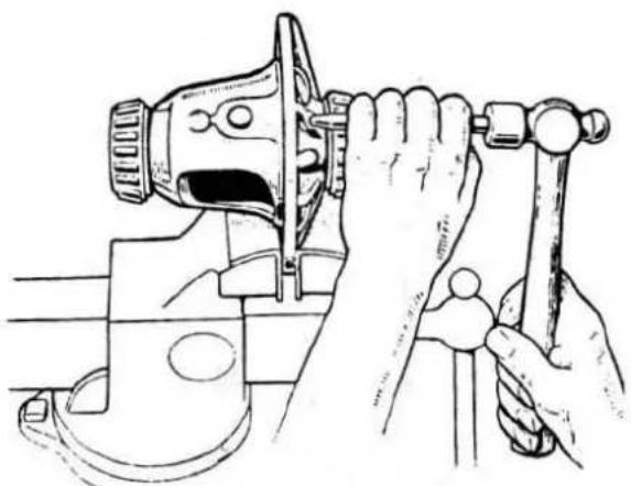
natural_image
Illustration of a hand using a chisel to adjust or install a mechanical clamp (no text or symbols present)Fig.8.11. Driving out the pinion mate shaft locking pin

FIG.8.10. SECTIONED VIEW OF THE CONVENTIONAL TYPE DIFFERENTIAL
1 Drive pinion oil seal
2 Drive pinion oil seal gasket
3 Drive pinion oil slinger
4 Gear carrier
5 Hypoid drive pinion) matched 12 Axle shaft spacer
6 Hypoid drive gear ) assembly 13 Pinion mate shaft

natural_image
Illustration of a mechanical press or lift device with hands operating it (no text or symbols visible)Fig.8.12. Removing a differential bearing
14 Differential bevel pinion mate
15 Pinion mate shaft lock pin
16 Drive pinion bearing (inner)
17 Drive pinion bearing shim (inner)
18 Drive pinion bearing spacer
19 Drive pinion bearing shim (outer)
20 Drive pinion bearing (outer)
21 Universal joint flange
9 Differential assembly, Thornton "Powr-Lok" - dismantling
1 Before dismantling commences, check for mating marks on the two halves of the casing (Fig.8.13). Make your own marks with a centre punch or a scriber if none are visible.
2 Refer to Fig.8.2.
3 Remove the eight bolts securing the two halves of the differential casing.
4 Split the casing and remove the clutch discs (3) and the plates (2) from one side.
5 Remove the differential side gear ring (5).
6 Remove the pinion side gear (6) and the pinion mate cross shafts (7) complete with the pinion mate gears.
7 Separate the cross shafts (10) by extracting the shaft spacers (12) from the spacer roll pin (11).
8 Remove the remaining side gear and the side gear ring.
9 Take out the remaining clutch discs and plates.
10 Differential unit, conventional type - reassembly, adjustment and refitting
1 Assemble the side gears complete with thrust washers.
2 Assemble the differential pinions through the openings in the differential case and mesh them with the side gears. Hold the pinion thrust washers on the spherical thrust faces of the pinions and at the same time turn the differential gear assembly by hand into its operating position.
3 After lining up the pinions and thrust washers, install the pinion mate shaft together with the axle shaft spacer.
4 Align the cross hole in the shaft with the hole in the differ-
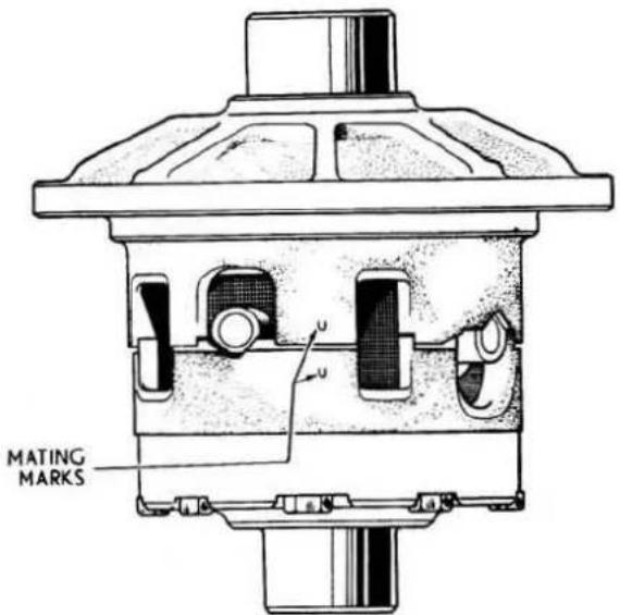
Fig.8.13. Mating marks on the differential case
ential case and fit the pinion mate shaft lock pin. Peen some of the metal of the differential case over the end of the lock pin to prevent it working loose.
5 Clean the mating surfaces of the crown wheel and differential case, carefully examine the faces for burrs and remove as necessary.
6 Line up the crown wheel attachment holes with those in the flange of the case and, keeping it square, gently tap the crown wheel home on the case using a hide faced hammer.
7 Assemble the crown wheel attachment bolts, use new locking straps, and tighten down to a torque of 50 to 60 lbs ft (6.9 to 8.3 kg f m).
8 Now make sure that the differential bearings, the bearing cones and cups and the seatings in the housing are perfectly clean.
9 Fit the differential bearings, without the shims, on the differential case.
10 Place the differential assembly, with the bearing cups in their housing, in the gear carrier. The pinion must not be in position at this stage.
11 Mount a Dial Test Indicator on the gear carrier as shown in Fig.8.14 in such a position as to take a reading on the back face of the crown wheel. Lever the differential assembly to one side of the carrier and set the indicator to zero at this position.
12 Move the assembly in the opposite direction and note the reading on the indicator, this represents the total clearance between the bearings as now assembled and the abutment faces of the gear carrier housing. Add 0.005" (0.13 mm) to the reading to give the desired degree of preload, the total amount (i.e. 0.005" plus recorded clearance) will be the thickness of shims to be used for installations of the differential bearings. The pack of shims will have to be divided to give the gear position with correct backlash as detailed in paragraph 37.
13 Remove the differential assembly from the gear carrier. 14 If you have removed the pinion outer bearing cup, reassemble it using Tool No: SL.550-4 with handle 550.
15 Refit the pinion bearing inner cup, if removed, complete with the original pack of adjusting shims.
16 Press the inner bearing into position on the pinion using a length of tube contacting the inner cage only.
17 The pinion must now be correctly adjusted and extreme care must be taken to ensure accuracy.
Note: The crown wheel and pinion are a matched assembly, they are lapped together at production and must be kept together as a set. The matched assembly serial number is stamped on the
ground end of the pinion and on the crown wheel.
18 Refer to Fig.8.15 which shows typical markings found on the ground end of a pinion. The figures at the top are the matched assembly number; the letter on the left is for production purposes only; the letter and figure on the right refer to the tolerance on offset or pinion drop dimension "A" in Fig.8.16 and this is also stamped on the cover facing of the gear carrier housing. Finally, the figure at the bottom gives the cone setting distance of the pinion from the centre line of the crown wheel and may be marked as Zero (O) or Plus (+) or Minus (-) followed by a figure; the figure represents thousandths of an inch to be added or subtracted from the Zero Cone Setting "B" shown at Fig.8.16.
19 Having assembled the pinion bearing cups with the original inner bearing adjusting shims, place the pinion, with the inner bearing assembled, in the gear carrier.
20 Turn the carrier over and support the pinion with a suitable block of wood.
21 Install the pinion bearing spacer (if fitted).
22 Pit the outer bearing shims on the shank of the pinion so that they seat on the shoulder of the pinion shank or on the spacer as may be applicable for the particular model.
23 Fit the outer bearing, the pinion flange for the propeller shaft and its washer and nut. Leave the oil slinger and the oil seal out at this stage. Tighten down on the nut.
24 The pinion cone setting distance must now be checked using the gauge, Tool No:SL.3, applied as shown in Fig.8.17.
25 Adjust the bracket carrying the indicator to suit the assembly and then set the indicator to zero with the setting block.
26 Place the indicator assembly on the fixed spindle of the gauge body.
27 Fit the fixed spindle of the gauge body into the centre hole in the face of the pinion, slide the moveable spindle into position locating in the centre hole with the gauge body underneath the gear carrier, lock the spindle with the screw.
28 Now check the pinion setting by taking a reading on the differential bore with the bracket assembly seated on the end face of the pinion. The correct reading will be the minimum obtained ie when the indicator spindle is at the bottom of the bore. Slight movement of the assembly will enable the correct reading to be easily ascertained, the reading will be the deviation of the pinion setting from the zero cone setting and note must be taken of the direction as well as the magnitude of any such deviation.
29 If the pinion setting is incorrect (see paragraph 18 and Fig.8.16) you will have to dismantle the pinion assembly to add or remove shims as required from under the bearing cup. Adjusting shims are available in thicknesses of 0.003", 0.005" and 0.010".
30 When the correct pinion setting is obtained, check the pinion bearing preload which should afford a slight drag or resistance to turning and there should be no end play on the pinion. The correct preload is 8 to 12 lbs f in (0.09 to 0.14 kg f m), less than this amount will result in excessive deflection of the pinion under load whilst too much preload will lead to failure of the bearings.
31 To adjust the preload, add or remove shims from between the outer bearing cone and the pinion shank or the spacer, as applicable. Do not touch the shims behind the inner bearing as these control the position of the pinion.
32 The position of the crown wheel must now be adjusted. 33 Place the differential assembly with bearing cups, less shims, in the housing but first make sure the bearing faces, cups and housing are perfectly clean.
34 Mount a Dial Test Indicator on the housing with the indicator button on the back face of the crown wheel as illustrated in Fig.8.14.
35 Lever the differential assembly away from the pinion until the opposite bearing cup is seated against the housing.
36 Now set the indicator to zero whilst bearing on the crown wheel and then move the assembly towards the pinion until the crown wheel is fully meshed with the pinion. The indicator reading at that position denotes the thickness of shims, less the
backlash allowance marked on the crown wheel ie B/L .005, B/L .007 etc, which must be fitted between the differential case and the bearing cone on the crown wheel side of the differential.
37 Install the thickness of shims, determined in the above operation, on the crown wheel side of the differential taking them from the pack determined in the operations at paragraph 12.
38 As an example of differential and crown wheel adjustment, assume that the indicator reading obtained at paragraph 12 is 0.070", add to this 0.005" for the recommended preload which makes the required pack of shims to be 0.075" in thickness. Also assume that the clearance, determined at paragraph 36, between the crown wheel and pinion is 0.040" and that the backlash etched on the crown wheel is 0.005"; subtracting 0.005" from 0.040" gives a figure of 0.035" which is the thickness of shims required to be fitted between the differential case and the bearing cone on the crown wheel side of the differential. Now subtract the 0.035" thickness of shims inserted on the crown wheel side from 0.075" (the total required) and the 0.040" difference is the thickness of shims to be fitted on the opposite side of the case.
39 The differential assembly can now be fitted into position. If you are using the stretching fixture as shown in Fig.8.7, fit it into position to stretch the gear carrier taking care not to exceed the specified half turn on the gear carrier.
40 Lower the differential assembly into position and lightly tap the bearings home using a hide faced hammer and at the same time ensuring that the gear teeth are led into mesh with those of the pinion.
41 It is possible to install the differential by slightly tilting the bearing cups and then tapping them into position with a hide faced hammer. We cannot really recommend this method as it increases the possibility or damage to the gear teeth and extreme care is necessary to avoid damage to the differential bearings.
42 Now fit the differential bearing caps but do ensure that the position of the numerals marked on the gear carrier housing face and the caps correspond as indicated in Fig.8.18.
43 Tighten the bearing cap bolts to a torque of 60 to 65 lbs f ft (8.3 to 9.0 kg f m).
44 The run out on the back face of the crown wheel must now be checked and this is done with a Dial Test Indicator mounted in the same manner as that employed for the differential bearing adjustment (paragraph 12 and Fig.8.14). Set the indicator button against the back face of the crown wheel and turn the
pinion by hand and at the same time watch the indicator to see that there is no movement in excess of 0.005" (0.13 mm), if there is, remove and strip the assembly and rectify by cleaning the surfaces locating the crown wheel and make absolutely sure there are no burrs on these surfaces.
45 Now transfer the indicator to give a reading on the teeth of the crown wheel as nearly in line with the direction of tooth travel as possible as illustrated in Fig.8.19. Move the crown wheel by hand to check the backlash which should be in accordance with that etched on the wheel. If the backlash is incorrect, trip the assembly to transfer the necessary shims from one side of the case to the other in order to obtain the required setting. Transfer shims from the crown wheel side of the differential and install on the opposite side to increase backlash and vice versa.
46 When satisfied with all settings, mark a number of the crown wheel teeth very sparingly with a marking compound, engineer's blue is suitable, and move the painted teeth into mesh with the pinion until a good impression of tooth contact is obtained. Refer to Fig.8.20 and take remedial action as may be necessary.
47 All the necessary adjustments have now been completed and final assembly can commence.
48 Remove the pinion nut, washer and the propeller shaft flange.
49 Install the oil slinger, the gasket as used with the metal cased type seal on later models and the oil seal with the dust excluder flange uppermost using Tool No: SL.4. Fit the installation collar of the tool (Fig.8.6) and then tighten down the pinion nut and washer to drive the assembly home. Remove the pinion nut and washer and the collar of the tool.
50 Fit the propeller shaft flange followed by the washer and pinion nut. Tighten the nut to a torque of 120 to 130 lbs f ft. (16.6 to 18.0 kg f m) and lock it with a new split pin.
51 Fit the rear cover gasket (we advise use of a new item) followed by the rear cover. Secure with the ten set bolts and spring washers but do not forget to replace the ratio/differential type indicator tag on one of the bolts.
52 Refit the axle shaft and hub bearings etc as described in Section 4.
53 Refit the drain plug.
54 Grease the hub bearings through the grease nipple on the axle case with a recommended lubricant.
55 Check for oil leaks after filling the axle with the appropriate quantity of lubricant and rectify as necessary.
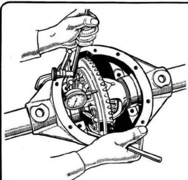
natural_image
Technical illustration of hands operating a mechanical assembly with gears and a dial (no text or symbols)Fig.8.14. Adjusting the differential bearings

natural_image
Technical line drawing of a mechanical gear or impeller with no visible text or symbolsFig.8.15. Markings on pinion

FIG.8.16. PINION SETTING DISTANCES
A Pinion drop
B Zero cone setting
C Mounting distance
D Centre line to bearing housing
3 HA Axle
1.375" (34.92 mm)
2.250" (31.75 mm)
3.937" (100.00 mm)
5.120" (130.05 mm)
to to
5.130" (130.30 mm)
4 HA Axle
1.5" (38.1 mm)
2.625" (66.67 mm)
4.312" (108.52 mm)
5.495" (139.57 mm)
to to
5.505" (139.83 mm)

natural_image
Technical illustration of a mechanical assembly with two pressure gauges (no text or symbols present)Fig.8.17. Checking the pinion cone setting
| TOOTH CONTACT(CROWN WHEELS) | CONDITION | REMEDY | |
| A | HEEL(outer en) | IDEAL TOOTHCONTACTEvenly spread overprofile, nearer toesthan heel. | |
| B | HEEL(outer en) | HIGH TOOTHCONTACTHeavy on the top ofthe drive gear toothprofile. | Move the DRIVEPINION DEEPERINTO MESH.i.e.,REDUCE the pinioncone setting. |
| C | HEEL(outer en) | LOW TOOTHCONTACTHeavy in the root ofthe drive gear toothprofile. | Move the DRIVEPINION OUT OFMESH.i.e., INCREASE the pinioncone setting. |
| D | HEEL(outer en | TOE CONTACTHard on the smallend of the drive gartooth. | Move the DRIVEGEAR OUT OFMESH.i.e., INCREASE backlash. |
| E | HEEL(outer en | HEEL CONTACTHard on the largeend of the drive gartooth | Move the DRIVEGEAR INTO MESHi.e., DECREASEbacklash but maintainminimum backlash asgiven in "Data" |
FIG.8.20. CONTACT MARKINGS ON CROWN WHEEL
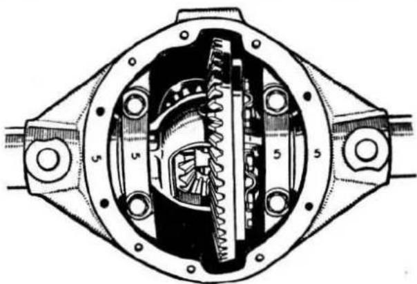
natural_image
Cross-sectional diagram of a mechanical assembly with internal gears and housing (no text or labels)Fig.8.18. Markings on differential bearing caps
11 Differential unit Thornton "Powr-Lok" type - reassembly, adjustment and refitting
1 Refit the clutch plates and discs alternatively into the flange half of the casing (Fig.8.21).
2 Fit the side gear rings so that the serrations on the gear mesh with those in the two clutch discs.
3 Place one of the side gears into the recess of the side gear ring so that the splines are both in line.
4 Fit the cross shafts both at the same time.
5 Use a new spacer roll pin, attach one axle shaft spacer to it and enter them through the hole in the cross shafts. Now press the other spacer on to the roll pin.
6 Refit the pinion mate cross shafts complete with their gears and ensure that the ramps on the shafts coincide with the mating ramps in the differential case.
7 Assemble the remaining side gear and side gear ring so that the splines are in alignment.
8 Fit the remaining clutch plates and discs to the side gear ring.
9 Check the alignment marks on the two halves of the differential case and offer up the bottom half to the flange half and position the tongues of the clutch friction plates so that they align with the grooves in the differential case.
10 Assemble the eight securing bolts but do not tighten down at this stage.
11 Check the alignment of the splines in the side gear rings and side gears by inserting the axle shafts and whilst they are in position, tighten the eight bolts to a torque of 35 to 45 lbs f ft (4.8 to 6.2 kg f m). If the bolts are tightening without the axle shafts in position it will be difficult, if not impossible, to enter them later.
12 The bearing preload and crown wheel and pinion adjustments for this type of differential are exactly the same as set out in Section 10 for the conventional type of differential.
13 Fit the rear cover gasket (we advise use of a new item) followed by the rear cover. Secure with the ten set bolts and spring washers but do not forget to replace the ratio/differential type indicator tab on one of the bolts.
14 Refit the axle shaft and hub bearings etc; as described in Section 4.
15 Refit the drain plug.
16 Grease the hub bearings through the grease nipple on the axle case with a recommended lubricant.

natural_image
Technical line drawing of a mechanical gear assembly with pressure gauge (no text or symbols)Fig.8.19. Checking backlash between the gears
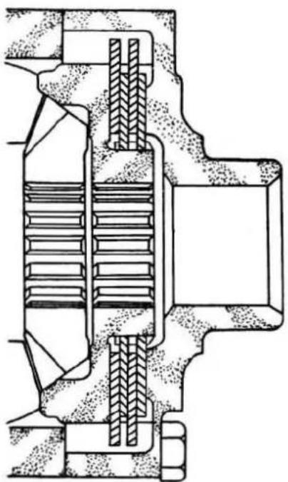
natural_image
Cross-sectional technical drawing of a mechanical assembly (no text or labels)Fig.8.21. Sectioned view showing friction discs and plates
Chapter 9 Braking system
Contents
| General description | 1 | Disc brakes - renewing the brake piston seals | ... | ... | 11 |
| Bleeding the hydraulic system | 2 | Handbrake - adjustment | ... | ... | 12 |
| Front brake shoes and wheel cylinder (drum brakes) - removal and refitting | 3 | Handbrake friction pads - removal and replacement | ... | ... | 13 |
| Handbrake friction pad carriers - removal and refitting | ... | ... | 14 | ||
| Rear brake shoes and wheel cylinder (drum brakes) - removal and refitting | 4 | Handbrake friction pad carriers - dismantling and re-assembly | ... | ... | 15 |
| Front drum brake wheel cylinder - dismantling, overhaul and reassembly | 5 | Brake pedal assembly - removal and refitting | ... | ... | 16 |
| Master cylinder - removal and refitting | ... | ... | 17 | ||
| Rear drum brake wheel cylinder - dismantling, overhaul and reassembly | 6 | Master cylinder - dismantling and reassembly | ... | ... | 18 |
| Brake servo unit - description | ... | ... | 19 | ||
| Disc brake friction pads - removal and refitting | 7 | Brake servo unit - removal and refitting | ... | ... | 20 |
| Front disc brake caliper - removal and refitting | 8 | Vacuum reservoir and check valve - description | ... | ... | 21 |
| Rear disc brake caliper - removal and refitting | 9 | Vacuum reservoir and check valve - removal and refitting | ... | ... | 22 |
| Front and rear discs - removal and refitting | 10 | Fault diagnosis | ... | ... | 23 |
Specifications
| Make | ||||||||
| Early cars | ... | ... | ... | ... | ... | ... | ... | Lockheed 'Brakemaster' Dunlop |
| Later cars | ... | ... | ... | ... | ... | ... | ... | |
| Type | ||||||||
| Early cars | ... | ... | ... | ... | ... | ... | ... | Drum type |
| Brake drum diameter | ... | ... | ... | ... | ... | ... | 11.1/8 in. (28.25 cm) | |
| Brake linings | ||||||||
| Length | ... | ... | ... | ... | ... | ... | ... | 8 12 in. (21.6 cm) |
| Width | ... | ... | ... | ... | ... | ... | ... | 2 14 in. (57.1 mm) |
| Thickness | ... | ... | ... | ... | ... | ... | ... | 14 in. (6.3 mm) |
| Material | ... | ... | ... | ... | ... | ... | ... | Ferodo MS3 |
| Identification | ... | ... | ... | ... | ... | ... | 2 blue and 2 yellow paint stripes on edge of lining (must be fitted to all four brakes, this material replaces Ferodo DM52 originally used) | |
| Later cars | ... | ... | ... | ... | ... | ... | ... | Disc type |
| Disc diameter | ||||||||
| Front | ... | ... | ... | ... | ... | ... | ... | 11 in. (27.9 cm) |
1 General description
The braking system comprises a master cylinder operated by the brake pedal, a vacuum servo unit connected to the inlet manifold and self adjusting front and rear brake assemblies.
The drum type system illustrated in Figs. 9.1 and 9.2, consists of a leading and trailing shoe which are of the internally expanding type whereby the shoes are moved outwards into contact with the rotating brake drum. One wheel cylinder per drum is provided but that of the front assembly is a differential area wheel cylinder so arranged that it applies greater thrust to the trailing shoe than to the leading shoe and so overcomes the inherent inefficiency of the trailing shoe, improves braking performance and ensures reasonably even wear on both shoes.
The disc type brake, illustrated in Figs. 9.3 and 9.4 comprises a disc mounted on the wheel hub and a braking unit (caliper) rigidly fixed to the front suspension member or to the rear axle as the case may be. The braking units are of fixed caliper design, each half of the caliper containing a piston which operates in a bore, both being interconnected so that under hydraulic pressure their pistons move towards each other and by this action bear on the rotating disc between two friction pads. The method of self adjustment is illustrated in Fig. 9.5 and a layout of the whole system is shown at Fig. 9.6.
Both drum and disc type systems are fitted with an independent mechanical handbrake unit operating on the rear wheels. The handbrake operates the brake shoes in the drum type system but for disc brakes it is entirely separate from the main brake assembly and has its own calipers and friction pads. The handbrakes of later cars fitted with disc brakes are self adjusting to compensate for friction pad wear.
The vacuum servo unit provides a degree of assistance when applying the footbrake and is installed in the hydraulic system between the master cylinder and the wheel cylinders. It consists of a servo piston, a hydraulic slave cylinder and an air control valve. Power for its operation is supplied by matching atmospheric pressure against partial vacuum from the inlet manifold.
2 Bleeding the hydraulic system
Whenever the brake system has been overhauled to the extent of disconnecting a hydraulic union, or the level of hydraulic fluid in the reservoir becomes too low, air will have entered the system and bleeding (expelling the air) will be necessary. During the following operations, the level of fluid in the reservoir should not be allowed to fall below half full, otherwise air will be drawn into the system again. The recommended brake fluid is Castrol Girling Universal Brake and Clutch Fluid. This conforms to SAE 70 R3 and where this is not available, only fluid guaranteed to conform to that specification should be used.
1 Obtain a clean and dry glass jar, a length of plastic tubing of suitable diameter to fit tightly over the bleed screw, and a supply of hydraulic fluid.
| Lockheed 5 12 in. up to chassis numbers:— | |
| RH drive | LH drive |
| 909060 | 942676 |
| 971731 | 987405 |
| Lockheed 6.7/8 in. all other models. | |
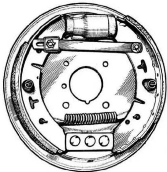
natural_image
Technical line drawing of a mechanical clutch assembly (no text or symbols)Fig.9.1. Drum brake front left hand (right hand similar but opposite way round)

natural_image
Technical line drawing of a mechanical clutch assembly (no text or symbols)Fig.9.2. Drum brake rear left hand (right hand similar but opposite way round)

natural_image
Technical line drawing of a mechanical assembly with no visible text or symbolsFig.9.3. Sectioned view of the front disc brake

FIG.9.4. EXPLODED VIEW OF TYPICAL REAR DISC BRAKE CALIPER ASSEMBLY
1 Brake caliper body
2 Friction pad
3 Support plate
4 Retaining plate
5 Retaining bolt
6 Nut
7 Shakeproof washer
8 Piston assembly
9 Cylinder block
10 Cylinder bolt
11 Shakeproof washer
12 Bleed screw and ball
13 Bridge pipe
14 Piston and backing
plate
14a Rubber dust excluder
15 Retractor bush
16 Piston seal
17 Piston seal plate
18 Screw
19 Shakeproof washer
20 Handbrake pad carriers
21 Inner pad carrier and
friction pad
22 Outer pad carrier and
friction pad
23 Operating lever
24 Adjuster bolt
25 Self-locking nut
26 Pivot seat
27 Clevis pin
28 Split pin
29 Washer
30 Handbrake friction pad securing bolt
31 Nut
32 Shakeproof washer
33 Pivot bolts
34 Retraction plate
35 Tab washer
36 Caliper mounting plate
37 Caliper centring shim
38 Brake disc

RETRACTOR BUSH DRAWN
ALONG PIN BY PISTON AS
PAD WEARS
SPRING WASHER UNDER TENSION
BUSH RETAINS ITS NEW POSITION ON PIN AND SPRING RETURNS TO NORMAL POSITION, THUS RESTORING CORRECT CLEARANCE BETWEEN PAD AND DISC
Fig.9.5. Self adjusting mechanism - disc brakes
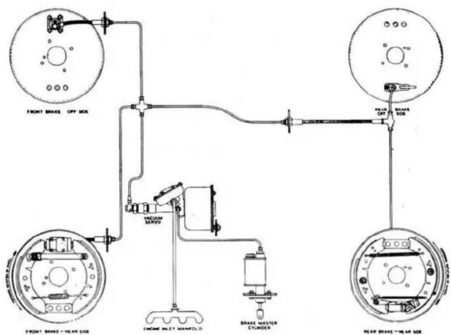
Fig.9.6. Layout of drum brake system (disc system similar except for connection at wheels)
2 Fill the master cylinder reservoir and the bottom inch of the jar with hydraulic fluid. Take extreme care that no fluid is allowed to come into contact with the paintwork as it acts as a solvent and will damage the finish.
3 Place the car over a pit or alternatively jack up each wheel to be worked on, in turn, commencing with the front nearside wheel. Ensure that the wheels are firmly chocked and that the raised wheel is adequately supported, preferably on an axle stand. Release the handbrake.
4 For those cars fitted with drum brakes, observe the position of the bleeder screws in the front brake assemblies; if they are not on the centre line it will be necessary to remove the road wheel and brake drum. Now remove the circlip securing the adjuster bar at one end and prise the bar off the anchor pin to allow the pull-off spring to close the pistons. Now clamp the brake shoes in same manner, wiring is recommended, to prevent the wheel cylinder pistons moving outwards when the brake pedal is depressed during the bleeding operation.
5 Remove the rubber dust cap (if fitted) from the bleed screw of the wheel being worked on, clean the bleed screw, and slide one end of the plastic tube over the screw and insert the other end of the tube in the jar of fluid. The location of the bleed screw on the disc brake caliper is shown in Fig. 9.7.
6 Use a suitable open ended spanner and unscrew the bleed screw about half a turn.
7 Have an assistant to depress the brake pedal slowly, allowing it to return and repeat the pumping action with a slight pause between each depression.
8 Watch the flow of fluid in the jar and when air bubbles cease to emerge with the next down stroke of the pedal hold the pedal at the bottom of its stroke and tighten the bleed screw when the pedal is in that position.
9 If it was found necessary to remove the front brake drums etc., as detailed in paragraph 4, remove the clamps from the shoes and reconnect the adjuster bars to the anchor pins and secure with the circlip. Refit the brake drum and the road wheel and now pump the brake pedal a few times in order to take up the adjustment.
10 Repeat the foregoing operations (where applicable) for all four wheels.
11 An illustration of the set up for bleeding the brakes (drum type brake illustrated) is given.
12 If after the above operation, the brake pedal still feels spongy, this is an indication that there is still air in the system or that the master cylinder is faulty and should be overhauled as detailed later in this Chapter.
13 Check and top up the reservoir with fresh hydraulic fluid. Never re-use once used old brake fluid.

natural_image
Technical illustration of a brake assembly with a brake caliper and wheel (no text or labels)Fig.9.7. Location of bleed screw - disc brakes
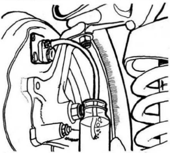
natural_image
Technical line drawing of a mechanical assembly with hoses and components (no text or labels)Fig.9.8. Bleeding the brakes
3 Front brake shoes and wheel cylinder (drum brakes) - removal and refitting
1 Chock the rear wheels, apply the handbrake, jack up the front of the car and support on firmly based axle stands. Remove the road wheel.
2 Remove the two screws securing the brake drum to the hub and remove the drum.
3 Refer to Fig. 9.9. Remove the circlip and plain washer at one end of the adjuster bar. Take out the split pin and remove the slotted nut at the other end of the bar. Lift off the plate and the top friction pad. Now remove the adjuster bar, the ratchet spring, the rear friction pad, the enclosing plate and the washer behind it. Be careful when taking off the ratchet spring to avoid straining it.
4 Now look at Fig. 9.1. Disengage the toe of the leading shoe from the wheel cylinder piston and pull the heel of the shoe out of its housing. As the load on the pull off spring is now released, the trailing shoe will come away.
5 Detach the hydraulic flexible hose from the frame connector (see Fig. 9.10) and now unscrew the hose from the banjo fitting on the wheel cylinder (on early models the hose screws directly into the wheel cylinder).
6 Remove the banjo bolt and take off the banjo noting the position of the two gaskets.
7 Knock back the tabs of the locking plates to the four bolts securing the wheel cylinder to the backplate. Remove the bolts and lift out the wheel cylinder noting which way round it is fitted.
8 Thoroughly clean all dust from the shoes, the backplate and the drum using a stiff wire brush. Do not use compressed air as this will raise dust which must not be inhaled as it is of an asbestos nature. As the dust can cause brake judder and squeal it is important to clean away all traces.
9 Check that each piston is free in its cylinder, the rubber dust covers are not perished or damaged and that there are no hydraulic fluid leaks.
10 Refitting is generally the reverse of the above procedure but particular attention must be paid to the following points.
11 Offer the wheel cylinder to the hole in the backplate so that the smaller rubber boot is pointing in the direction of forward rotation of the wheel. Secure it with the four bolts using new locking plates, tighten down on the bolts and lock with the tabs.
12 Place the large gasket under the head of the banjo bolt followed by the banjo and the smaller gasket, and assemble to the inboard connection on the wheel cylinder.
13 Screw the hose into the banjo, use a new gasket and connect the other end of the hose to the frame connector. Make sure, by holding the union with a spanner, that the hose does not twist
whilst you are tightening the locknut.
14 The brake shoes can now be assembled. Look at the shoes and you will see that the linings are shorter in length than the platforms on which they are rivetted. The end with the greater length of platform exposed is known as the "toe" and the other end is known as the "heel" of the brake shoe. When installed on the backplate, the tow of the leading shoe is to be against the smaller rubber boot of the wheel cylinder whilst the headl of the shoe engages the slot in the fixed housing at the bottom of the backplate. The correct condition is plainly shown in Fig. 9.1.
15 Place in position on the brake shoe the bolt, and its coil spring, securing the adjuster plate.
16 Hook the pull-off spring into the correct holes so that it is on the underside of the shoes.
17 Offer up the shoes to the backplate with the spring inside and engage the tips of one shoe with the respective slots in the wheel cylinder and the fixed housing. Now engage the tip of the other shoe in one of the slots and lift the other tip into position against the load of the spring.
18 Assemble the ratchet spring to the toothed end of the adjuster bar.
19 Assemble the inner plate pad followed by the friction pad to the adjuster plate bolt. It will be noted that the holes through the friction pads and the plates are off centre, they must be fitted so that the hole is nearer to the closed end of the ratchet spring.
20 Assemble the adjuster bar with teeth to the bottom and so that the ratchet spring encloses the inner friction pad.
21 Place the outer friction pad and pad plate in position and then fit the slotted nut hand tight.
22 Gently ease the ratchet spring away from the teeth on the adjuster bar and then adjust the position of the bar so that the anchor pin in the trailing shoe can enter the hole in the bar, the pin must abut the inner edge of the hole.
23 Fit the washer and circlip to the anchor pin.
24 Tighten the slotted nut hard down and now slacken back two flats and lock with the split pin.
25 Check the operation of the adjuster by pulling on the heel of the trailing shoe so that the anchor pin moves to the outer edge of the hole. When released from this position the shoe must return smartly to the fully off position.
26 Refit the brake drum and the road wheel.
27 Bleed the system in the manner described in Section 2.
28 Pump the brake pedal a few times to take up all adjustment in the brake.

Fig.9.10. Hold 'A' when unscrewing or tightening 'B' or 'C'
4 Rear brake shoes and wheel cylinder (drum brakes) - removal and refitting
1 Securely chock the front wheels. Jack up the rear of the car and remove the road wheel. Place a firmly based axle stand in position.
2 Release the handbrake. Remove the split pin and the clevis pin securing the handbrake cable to the lever at the wheel cylinder, pull the cable away from the lever and place it out of the way.
3 Remove the four screws securing the brake drum to the hub and pull off the drum.
4 Pull on the tip of the adjustment lever to disengage it from the ratchet wheel, allow the lever to rotate to relieve tension on the spring and then unhook the spring from the lever and the brake shoe.
5 Remove the circlip from the lever axis pin and take off the washer underneath it and then take off the lever.
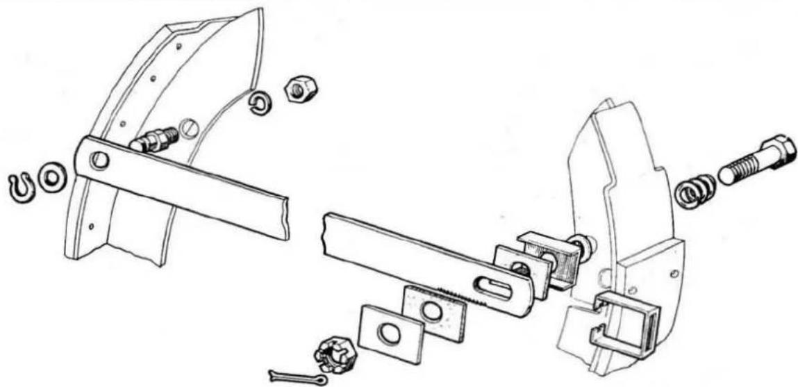
natural_image
Technical line drawing of mechanical components and fasteners (no text or symbols)Fig.9.9. Adjuster bar arrangement (right hand front illustrated)
6 Take out the two steady springs passing through the back-plate by depressing them and twisting.
7 Pull on the toe of the leading shoe to disengage it from the wheel cylinder. Take off the ratchet wheel and the cam assembly from the shoe.
8 Pull the heel of the shoe out of its slot in the fixed mounting. Tension on the spring will now be released and the other shoe will fall away.
9 Disconnect the hydraulic pipe from the wheel cylinder and remove the rubber boot from the handbrake lever and the wheel cylinder.
10 Remove the wheel cylinder outer piston (Fig. 9.12), and now slide the cylinder casting forward and at the same time pivot it about its forward end and withdraw the rear end from the slot in the backplate. Rearward movement of the cylinder will now bring its forward end clear of the backplate.
11 Thoroughly clean all dust from the shoes, the backplate and the drum using a stiff wire brush. Do not use compressed air.
12 Clean the backplate and the cylinder bearing surfaces and make sure that the cylinder moves freely on the backplate.
13 Check that each piston is free in its cylinder, the rubber covers are not perished or damaged and that there are no hydraulic fluid leaks.
14 Refitting the brake assembly is generally the reverse of the above procedure.
15 Place the lever through the slot in the backplate and, with the piston pointing in the forward rotation of the wheel, engage the forward end of the cylinder in the slot and slide it well forward. Engage the rear end in the slot and slide the cylinder back to hold it in position.
16 Fit the rubber boot to the lever and the wheel cylinder body. 17 Replace the outer piston.
18 Examine the brake shoes and it will be seen that the linings are shorter in length than the platforms to which they are rivetted. The end at which the greater portion of platform is exposed is known as the "toe" and the opposite end is known as the "heel", of the shoe.
19 When installed on the backplate, the toe of the leading shoe is to be adjacent to the wheel cylinder piston, whilst the toe of the trailing shoe engages a slot in the fixed housing. This condition is clearly shown in Fig. 9.2.
20 Hook the larger pull-off spring into the appropriate holes in the shoes so that it will lie on the upper surface when assembled.
21 Offer up the shoes to the backplate with the pull-off soring on the outside. Engage one shoe in its slots and then engage one end of the other shoe in a slot and then pull its other end into position.
22 Pull back the toe of the leading shoe slightly to allow assembly of the ratchet wheel and cam in the slots in the shoe. The ratchet wheel is to be on the outside so that it will engage the spring pawl and also the commencement of the cam form is to be adjacent to the wheel cylinder piston.
23 Pass the stems of the steady springs through the holes in the shoes and engage with the backplate by depressing and twisting them.
24 Place the adjustment lever on the pin in the trailing shoe so that it points outwards, assemble the washer and circlip to secure it in position.
25 Hook the adjustment lever spring into the appropriate hole in the leading shoe and into the hole in the adjustment lever and now rotate the lever into position so that it correctly engages the teeth on the ratchet wheel.
26 Pull on the heel of the trailing shoe and check that the spring pawl prevents the ratchet wheel from rotating. Allow the lever pawl to click into position in a fresh tooth and ensure that when the brake shoe is released the ratchet wheel is rotated. After this check, pull on the toe of the leading shoe to back-off the adjustment and bring the ratchet wheel back to its original position.
27 Refit the brake drum. If difficulty is experienced in getting it over the brake shoes, suspect that adjustment, as per paragraph 26, has not been backed-off sufficiently.
28 Refit the hydraulic fluid pipe to the wheel cylinder. Note that, if the bleed screw has been removed and not refitted at this
stage, the pipe assembles in the connection nearest to the lever.
29 Connect the handbrake cable to the lever and use a new split pin to secure the clevis pin.
30 Refit the roadwheel.
31 Bleed the system as described in Section 2.
32 Pump the brake pedal a few times to take up all adjustment.
5 Front drum brake wheel cylinder - dismantling, overhaul and reassembly
1 Thoroughly clean the exterior of the cylinder to remove all trace of road dirt. Maintain absolute cleanliness when stripping the cylinder and to this end it is advisable to cover the top of the bench on which you are working with clean cloth or paper. Under no circumstances allow oil or grease to come into contact with any of the rubber components.
2 Refer to Fig. 9.11 which gives an exploded view of the cylinder.
3 Disengage the larger rubber boot from the piston end (2) and from the groove in the cylinder body.
3 Take out the piston end followed by the spring and the piston pin (4).
4 Disengage the rubber boot from the smaller piston (10) and from its groove in the cylinder body.
5 Using your fingers, push the piston from the smaller end through the bore to extract the larger piston (6), the cup (7), the cup filler (8) and the taper spring followed by the small piston.
6 Remove the taper seal (11) from the small piston by easing it out of its groove.
7 Clean all items in fresh brake fluid.
8 Examine the cylinder bore and the pistons for scores or abrasions as these may cause leaks. If in doubt as to their condition it is advisable to obtain a new cylinder assembly.
9 Any rubber component showing signs of wear, perishing or swelling should be renewed but it is as well to obtain a repair kit and replace these items as a matter of course.
10 Commence reassembly by fitting the larger end of the taper spring into the cup filler and enter them into the body with the spring leading.
11 Smear the rubber cup with hydraulic fluid and push it into the body with the lip leading. Be very careful not to turn back the lip or to buckle it.
12 Now insert the piston with its flat face leading and then pass the stem of the piston pin through it and the cup and cup filler. 13 Locate the spring on the piston pin followed by the piston end.
14 Stretch the large rubber boot onto the piston end and then work it into its groove in the body.
15 Smear the tapered rubber seal with brake fluid and then work it into its groove in the small piston, note that the seal is assembled larger end first, that is to say with the small end at the slotted end of the piston.
16 Fit the small piston to the body with its slotted end outwards taking care to ease the seal evenly past the edge of the bore.
17 Stretch the small rubber boot onto the piston and make sure that it seats properly in its groove in the body.
6 Rear drum brake wheel cylinder - dismantling, overhaul and reassembly
1 Thoroughly clean the exterior of the cylinder to remove all trace of road dirt. Maintain absolute cleanliness when stripping the cylinder and to this end it is advisable to cover the top of the bench on which you are working with clean cloth or paper. Under no circumstances allow oil or grease to come into contact with any of the rubber components.
2 Refer to Fig. 9.12 which gives an exploded view of the cylinder.
3 Lift off the rubber boot.
4 Withdraw the outer piston (7). Tap out the lever axis pin and remove the lever (1).

FIG.9.11. EXPLODED VIEW OF THE FRONT WHEEL CYLINDER
1 Rubber boot
2 Piston end
3 Spring
4 Piston pin
5 Body
6 Piston
7 Rubber cup
8 Cup filler
9 Taper spring
10 Piston
11 Rubber seal
12 Rubber boot
5 Try to shake out the inner piston (5). If this will not shift it, apply a low air pressure (foot pump) to the hydraulic pipe connection but be careful to catch the piston as it is expelled because if it falls onto a hard floor it will be damaged beyond repair.
6 Ease the rubber seal out of its groove in the outer piston (7) and the inner piston (5).
7 Clean all parts in fresh hydraulic fluid.
8 Examine the bore in the body and the pistons for wear, scores or abrasions as may cause leaks. If you are in any doubt about their condition it is advisable to renew the assembly.
9 Examine the rubber components for signs of wear, perishing or swelling and renew as necessary. We feel that it is as well to obtain a repair kit and replace these items as a matter of course. 10 Commence reassembly by easing the rubber seal (6) into the groove in the outer piston.
11 Fit the rubber seal (4) into its groove in the inner piston making sure that the larger end is facing away from the slotted end of the piston.
12 Enter the inner piston in the body with the end fitted with the seal leading and so that the widest part of the slot is adjacent to the slot in the body. Take care not to damage the seal when easing it past the edge of the bore.
13 Place the lever in position and fit the pin.
14 Insert the outer piston turning the seal onto its side so that the edge which tends to protrude enters the bore last.
15 Place the rubber dust cover in position.
7 Disc brake friction pads - removal and refitting
1 The minimum permissible thickness of friction pads including backing plate is 14 inch (7 mm) after which the pads complete with backing plates should be renewed.
2 Jack up the car, remove the road wheel and support the car on a firmly based axle stand.
3 The friction pad assembly is illustrated in Fig. 9.13.
4 Remove the nut, washer and bolt securing the keep plate and remove the plate.
5 Due to the self adjusting feature of the brakes the pad will be within approximately 0.005 inch of the disc; it is possible that the disc will have worn slightly throwing up a ridge on the periphery which will be accentuated by road dirt and rust and which will, because of the small clearance, possibly obstruct removal of the pad, so make sure that any ridge as may be

FIG.9.12. EXPLODED VIEW OF REAR DRUM BRAKE WHEEL CYLINDER
1 Handbrake operating lever
2 Rubber boot
3 Body
4 Rubber seal
5 Inner piston
6 Rubber seal
7 Outer piston
8 Lever axis pin
present is cleaned off.
6 Engage a hooked implement in the hole in the lug of the pad securing plate and withdraw the pad assembly.
7 Repeat the foregoing for the other pad at that particular wheel.
8 Thoroughly clean the backing plate and the surrounding area of the pad.
9 If new pads are being fitted always use those manufactured to the recommended specifications given at the beginning of this Chapter.
10 In order to fit new pads, which will be of increased thickness to those removed, it will first be necessary to reset the pistons to their outermost position. Before doing this, partially empty the brake supply tank to accommodate the fluid displaced by the pistons.
11 A special tool is available for resetting the pistons but this work can be done using a stout screwdriver to lever on the end of the piston. The main point to watch is keeping the piston square in the bore, if the piston becomes tilted and is levered in that condition, it, or the cylinder bore, will be damaged.
12 Having moved the piston out of the way, insert the friction pad, replace the keep plate and secure with the nut and bolt.

natural_image
Technical line drawing of a mechanical device with a bracket and housing (no text or symbols)Fig.9.13. Removing a friction pad
8 Front disc brake caliper - removal and refitting
1 Jack up the car and remove the road wheel. Support the car on a firmly based axle stand.
2 Disconnect the flexible hydraulic pipe at the caliper mounting bracket and plug the unions to prevent the ingress of dirt.
3 Break the locking wire to the two mounting bolts. Remove the bolts and carefully withdraw the caliper assembly to note the position and number of shims fitted between the assembly and the mounting bracket.
4 Reassembly is the reverse of the above procedure but fit the original shims and secure with the two bolts.
5 Check the gap between each side of the caliper and the disc both at the bottom and at the top. The difference should not exceed 0.010 inch (0.25 mm), remove or add shims as necessary to centralise the caliper body (see Fig. 9.14).
6 Lockwire the two mounting bolts using soft iron locking wire or alternatively annealed copper wire (to anneal the wire, heat to red heat and allow to cool or quench in water).
7 If you removed the bridge pipe, connecting the two cylinder assemblies, remember that it must be fitted with the hairpin bend in the inboard cylinder block.
8 Refit the flexible hydraulic pipe making sure that you do not twist it whilst tightening down.
9 Bleed the brake system as described in Section 2 and check for leaks.
10 Refit the road wheel.

natural_image
Technical line drawing of a mechanical assembly with no visible text or symbolsFig.9.14. Location of caliper adjustment shims
9 Rear disc brake caliper - removal and refitting
1 Jack up the car and remove the road wheel. Support the car on a firmly based axle stand.
2 Withdraw the split pin and take out the clevis pin attaching the handbrake cable to the operating lever.
3 Disconnect the main hydraulic fluid pipe at the caliper and plug the unions to prevent the ingress of dirt.
4 Break the locking wire to the two mounting bolts, remove the bolts and carefully lift off the caliper assembly, complete with the handbrake calipers, noting the number and position of shims between the caliper assembly and the mounting bracket.
5 Refitting is the reverse of the above. The caliper assembly must be centralised as described in Section 8 for the front caliper assembly.
6 Reconnect the handbrake to the operating lever using a new split pin to secure the clevis pin.
7 Bleed the system as described in Section 2 and check for leaks.
8 Refit the road wheel.
10 Front and rear discs - removal and refitting
1 Jack up the car to remove the appropriate road wheel. Support the car on a firmly based axle stand.
2 Refer to Sections 8 and 9 and remove the brake caliper assembly.
3 Refer to Chapter 8 or to Chapter 11 and follow the instructions for removing the rear or front hubs as the case may be.
4 Remove the five nuts and bolts with spring washers securing the disc to the hub and remove the disc.
5 To reassemble, first secure the disc to the hub with the five nuts and bolts.
6 Refit the hub to the car and now check the end float of the wheel hub bearings and adjust as necessary in the manner described in Chapters 8 or 11, as applicable, so that the end float does not exceed 0.005 inch (0.13 mm) otherwise the brakes may tend to drag and not function properly.
7 Check the disc for true rotation by clamping a Dial Test Indicator in a convenient position so that the button of the indicator bears on the disc. Rotate the disc and check it for truth, the "run-out" should not exceed 0.006 inch (0.15 mm): If this amount is exceeded, check the components for damage especially the mating surfaces of the disc and the hub. If there is no visible cause for the trouble, suspect that the disc is distorted and verify by checking against another item.
8 Refit the caliper assembly and check for centralisation as set out in Section 8 or 9.
9 Bleed the brake system and check for leaks.
10 Refit the road wheel.
11 Disc brakes - renewing the brake piston seals
Leakage past the brake piston seals will be denoted visually by an accumulation of oil in the area of the brake caliper and by a fall in level of fluid in the reservoir. In bad cases a spongy pedal action may be noticed. You are advised also to fit a new dust seal when renewing the piston seal.
1 Remove the friction pads as described in Section 7.
2 Disconnect and blank off the main hydraulic pipe. Remove and blank off the bridge pipe between the calipers.
3 Remove the four bolts securing the cylinder blocks to the calipers and remove them.
4 Thoroughly clean all dirt from the exterior of the cylinder blocks before you start to dismantle them.
5 Take off the dust seal from its groove around the face of the cylinder block.
6 Connect the cylinder block to a low pressure air source to eject the piston assembly.
7 For older models (Fig. 9.15 and Fig. 9.4), remove the screws securing the plate to the piston. Lift off the plate and the piston seal and withdraw the retractor bush from within the piston bore. Support the backing plate and press out the piston. Discard the dust seal.
8 On later type cars carefully push out and remove the piston seal and dust seal using a blunt screwdriver.
9 Check that the piston and cylinder bore are clean and show no sign of damage.
10 For older models, engage the collar of a new dust seal with the lip on the backing plate but be careful not to stretch the seal too much. Locate the backing plate on the piston spigot and with the piston suitably supported, press the backing plate fully home. Insert the retractor bush into the bore of the piston. Lightly smear the new piston seal with brake fluid and fit it to the piston face. Attach the plate to the piston with the two screws and then peen some of the metal of the plate into the screw slots to lock them.
11 Smear the piston and seals of later models with brake fluid and then work the seal onto the piston using the fingers only.

Fig.9.15. Front brake caliper assembly (earlier type cylinder assembly illustrated)
Locate the retractor pin in the retractor bush in the piston and then insert the washer, spring and spring housing, in that order, in the bore of the cylinder.
12 For both types, press the piston assembly into the cylinder bore and during this operation ensure that the piston is square to the bore and that the piston seal does not become twisted or trapped as it enters.
13 Engage the outer rim of the dust seal in the groove around the cylinder block face and make sure that the two support plates are in position.
14 Refit the cylinder blocks to the calipers and secure with the four bolts.
15 Refit the friction pads and secure in position with the keep plate and the nut and bolt.
16 Refit the bridge pipe between the calipers and make sure that the "hair pin" bend portion is connected to the inboard cylinder block, that is the block furthest from the road wheel. The bridge may have an identification sleeve marked "Inner Top".
17 Reconnect the main hydraulic pipe.
18 Bleed the brake system as described in Section 2 and check for leaks.
19 Refit the road wheel.
12 Handbrake - adjustment
1 The automatic adjustment feature of the rear drum brakes will normally keep the handbrake in correct adjustment and no attention should be necessary.
2 If an excessive amount of handbrake lever travel is obtained, the cable can be adjusted, on those cars fitted with a yoke type compensator, by means of the hexagonal nut at the front end of the handbrake cable. Fully release the handbrake and turn the nut clockwise until all slack is taken out of the cable but be sure that the cable is not under tension. Jack up each rear wheel in turn and rotate the wheel with the handbrake off to be sure that the brake is not binding.
3 For those cars fitted with a scissors type compensator, first release the handbrake. Remove the clevis pin securing the fork end to the operating link and now slacken the locknut and turn the fork end in the required direction so that when the clevis pin is refitted there is no slack in any of the three cables, ensuring, of course that they are not under tension. Jack up each rear wheel in turn, make sure that the handbrake is fully released, and rotate the wheel to check that the brake is not binding.
4 Cars equipped with disc brakes have a handbrake system entirely independent of the foot brake. The position of the friction pads in relation to the disc had to be hand adjusted in early models, but this type was superseded by self adjusting calipers; both types are illustrated in Figs. 9.16 and 9.17 respectively. Provision on both types is made for adjustment of the main cable in cases where excessive brake lever travel is experienced.
5 To adjust the calipers on the early type, jack up each rear wheel in turn and remove the wheel. A slotted adjustment bolt will be seen at the top of the caliper and clockwise rotation of this bolt will bring the friction pads closer to the disc. (photo)
6 Refit the road wheel and, with the handbrake fully released, check that the brake is not binding.
7 Adjustment of the main handbrake cable is provided at the fork end connecting to the compensator lever (Fig. 9.19). Make sure that the hand brake is fully released, remove the split pin and the clevis pin securing the fork end of the cable to the compensator lever, undo the locknut and adjust the fork end so that, when it is refitted to the compensator lever, there is no slack in any of the cables but they must not be under tension. Jack up each rear wheel in turn and check that the brake is not binding. Tighten up the locknut at the fork end and fit a new split pin in the clevis pin.
13 Handbrake friction pads - removal and replacement
1 Securely chock the front wheels, release the handbrake and

natural_image
Technical line drawing of a brake assembly with a circular component and bracket (no text or labels)Fig.9.16. Handbrake caliper (early type). Position of adjuster bolt arrowed

natural_image
Dark, low-resolution image showing indistinct curved shapes and a central vertical line (no text or symbols)12.5. Adjusting the handbrake caliper
select neutral gear.
2 Jack up the rear of the car and remove the road wheels. Place a firmly based axle stand in position to support the car.
3 Slacken off the handbrake adjuster bolt (first remove the split pin locking the bolt on the self adjusting type) until its end is flush with the nut on the inner handbrake pad carrier.
4 Slacken the nut in the side face of the pad carrier. (photo)
5 Pull out the friction pad using, if necessary, a hooked tool in the hole in the securing plate. (photo)
6 Fit the new friction pads into the carriers with the short face pointing upwards and ensure that the pad securing plate locates correctly over the head of the retaining bolt which protrudes through the inside face of the pad carrier. Tighten down on the nut to secure the friction pads.
7 Reset the forked shaped retraction plates by slackening, after knocking back the locking tabs, the two pad carrier pivot bolts and retightening. Lock the bolt heads by knocking up the second pair of tabs on the locking plate.
8 Adjust the position of the friction pads in the manner described in Section 12 for the non self adjusting type.
9 For the self adjusting type, screw up on the adjuster screw until there is a distance of 7/16 inch (11.1 mm) between the friction pads (this will give 1/32 inch clearance of each pad from the disc). Replace the split pin to lock the adjuster bolt. Rotate the disc to make sure the brake is not binding.
10 Refit the road wheels.
14 Handbrake friction pad carriers - removal and refitting
1 Firmly chock the front wheels and release the handbrake.
2 Jack up the rear of the car and remove the road wheels. Support the car on firmly based axle stands.

FIG.9.17. SELF ADJUSTING HANDBRAKE ASSEMBLY
A Operating lever
B Friction pad carrier
C Pawl
D Ratchet nut
E Adjuster bolt
F Friction pads


FIG.9.18. THE HANDBRAKE ACTUATING MECHANISM (LATER TYPE)
1 Handbrake lever assembly
2 Cross shaft assembly
3 Shaft housing
4 Rubber seal
5 Handbrake lever to cable
6 Clevis pin
7 Primary cable
8 Rear fork end
9 Clevis pin
10 Universal jaw
11 Clevis pin
12 Compensator lever
assembly
13 Rear axle bracket
14 Felt seal
15 Fulcrum pin assembly
16 Balance lever assembly
17 Bush bearing
18 Spindle assembly
19 Washer
20 Return spring
21 Nut
22 R.H. cable assembly
23 L.H. cable assembly
24 Clevis pin
25 Interrupter switch
26 Switch bracket
27 Switch operating bracket
3 Remove the split pin and withdraw the clevis pin attaching the handbrake cable to the brake operating lever.
4 Knock back the tabs of the locking plate and unscrew the two pivot bolts. (photo) It will be seen that these bolts are screwed under the head and some difficulty, due to rust etc., can be anticipated in getting them out after the thread is clear. You may have to resort to holding the head of the bolt with a mole wrench and then work the bolt backwards and forwards and at the same time pulling in an upward direction.
5 Lift off the friction pad carrier assembly.
6 Refitting is the reverse of the above procedures but it must be noted that the retraction plates are "handed" on late model cars and it is essential that these plates are fitted in the correct position.
7 To check for correct hand, lay the plates on a flat surface with the prongs and locating extensions pointing upwards. It will be seen that one of the plates has a square cut face uppermost. This plate must always be fitted to the left hand caliper.
8 When fitting these plates, place the prongs in the holes in the pad carriers. Position the lower locating extension between the upper and lower bridge clamps and secure the clamps to the caliper with the two pivot bolts. Check that the retraction plate location extension is free to move between the bridge clamps when secured and that the handbrake mechanism is operating correctly.
15 Handbrake friction ped carriers - dismantling and reassembly
1 Remove the friction pad carriers from the car as described in Section 14.
2 For the non self adjusting type, separate the friction pad carriers by unscrewing the adjuster bolt (photo), but take care to control the run of the self-locking nut in the forked end of the operating lever.
3 Detach the pivot seat from the forked end of the operating lever by taking out the split pin and withdrawing the clevis pin. Do not attempt to remove the spring or the squared nut unless these are damaged.
4 Remove the friction pads in the manner described in Section 13.
5 The self adjusting type is dismantled by first removing the cover securing bolt and withdrawing the pivot clevis pin.
6 Remove the dust cover and take out the split pin locking the adjuster bolt. Unscrew the adjuster bolt from the ratchet nut and withdraw the nut and the bolt.
7 Detach the pawl return spring and withdraw the pawl over the locating dowel.
8 Disengage the operating lever return spring and remove the operating lever and the lower cover plate.
9 Remove the friction pads in the manner described in Section 13.
10 Reassembly is the reverse of the above procedures.
natural_image
Close-up of a metallic tool interacting with a dark surface, possibly a mechanical or electrical component (no visible text or symbols)13.4. Friction pad securing nut

natural_image
Close-up of two hands in a dark, textured surface (no visible text or symbols)13.5. Removing the friction pad

natural_image
Close-up of a dark, textured surface with a small bright object near the center (no visible text or symbols)14.4. Handbrake caliper pivot bolt

natural_image
Black-and-white photo of a dark, abstract shape resembling a stylized human face or organic form, with no visible text or symbols.15.2. Separating the friction pad carriers

natural_image
Technical line drawing of a mechanical assembly with no visible text or symbolsFig.9.19. Adjustment of main handbrake cable
16 Brake pedal assembly - removal and refitting
The brake pedal is removed complete with its common mounting block with the clutch pedal in the manner described in Chapter 5.
17 Master cylinder - removal and refitting
1 Remove the split pin and take out the clevis pin securing the push rod to the brake pedal. To do this, push the front seat back to its full extent in order to give better access.
2 Have a clean container ready, disconnect the two hydraulic pipe unions and collect the fluid draining from the reservoir. Blank off the pipe and the master cylinder unions to prevent the ingress of dirt.
3 Remove the nuts and the spring washers from the mounting flange and lift off the cylinder.
4 Refitting is the reverse of the above procedures.
18 Master cylinder - dismantling and reassembly
Depending on the age of your car, one of three types of master cylinder will be fitted. The first, fitted to early cars, is identical with the clutch master cylinder described in Chapter 5 with the exception of differences, for identification purposes, in the hydraulic union nut as illustrated in that Chapter. This type of cylinder was superseded by a Dunlop unit and this was later replaced by a Girling unit. Both latter types have a separate hydraulic fluid reservoir. The method of operation of the Dunlop and Girling units is very similar but there are differences in the dismantling and reassembly procedures. These master cylinders are illustrated in Figs. 9.20 and 9.21 respectively.
1 Paragraphs 2 - 14 inclusive deal with the dismantling and reassembly of the Dunlop unit. Maintain absolute cleanliness throughout the whole of this operation.
2 Ease the dust excluder clear of the head of the master cylinder.
3 Using a pair of suitable pliers, remove the circlip to release the push rod complete with the dished washer.
4 Withdraw the piston complete with the return spring and the spring support and the valve assembly.
5 Remove both seals from the piston and remove the seal from the end of the valve.
6 Examine the bore of the cylinder for scores or abrasions as may cause leakage and if either of these are present, the unit should be replaced.
7 We strongly recommend that you replace all seals as a matter of course irrespective of their visual condition.
8 Lubricate the valve seal with the hydraulic fluid and assemble it to the end of the valve making sure that the lip registers in the groove.
9 Lubricate the piston seals with hydraulic fluid and fit them in their grooves around the piston.
10 Insert the piston into the spring support and assemble the return spring and the valve. Lubricate the piston with Girling Rubber Grease.
11 Smear the cylinder bore with hydraulic fluid and slide the piston/valve assembly into the bore taking care not to damage or twist the seals.
12 Enter the push rod against the head of the piston and depress the piston sufficiently to allow the dished washer to seat on the shoulder at the head of the cylinder.
13 Fit the circlip and check that it is fully engaged with the groove.
14 Fill the dust excluder with Girling Rubber Grease and refit it round the head of the cylinder.
15 The following paragraphs deal with the dismantling and reassembly of the Girling master cylinder.
16 Release the crimping and take off the metal end cap.
17 Using a suitable pair of pliers, take out the circlip from the groove in the top of the cylinder bore.
18 Withdraw the push rod complete with the dished washer and dust seal.
19 The return spring will now push the piston and the non-return valve out of the bore.
20 Lift the prong of the spring seat out of the piston recess and remove the plunger and spring retainer.
21 Remove the non-return valve seal and the piston seal.
22 Examine the bore for scores or abrasions as may cause leakage, if either of these are present, the unit should be replaced.
23 We strongly recommend that you replace all seals as a matter of course irrespective of their visual condition.
24 Lubricate the piston and the non-return valve seals with hydraulic fluid and assemble them in their respective positions. 25 Lubricate the bore of the cylinder with hydraulic fluid and carry on to reassemble the unit in the reverse order to the above taking great care not to damage or twist the seals when inserting them into the bore.

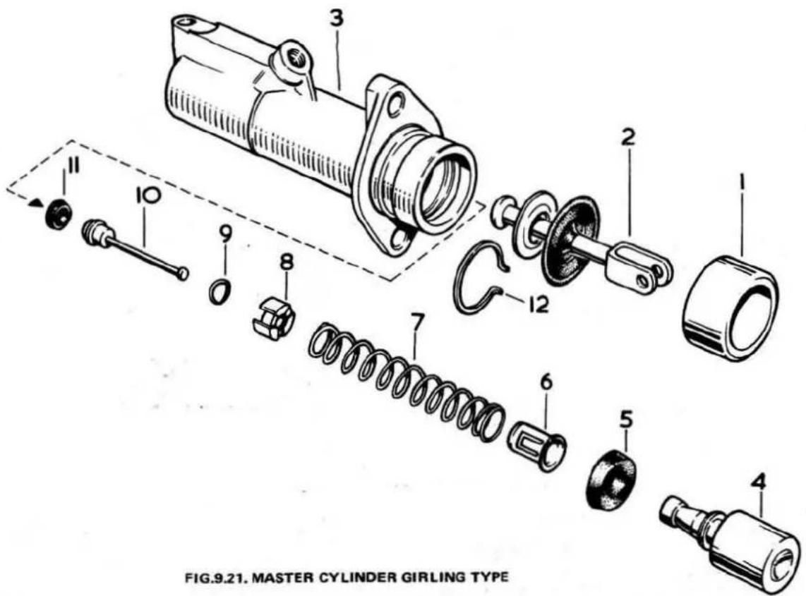
1 End cap
2 Push rod assembly
3 Body
4 Piston
5 Piston seal
6 Spring seat
7 Return spring
8 Plunger
9 Waved washer
10 Valve piston
11 Valve seal
12 Circlip
19 Brake servo unit - description
A vacuum servo unit is fitted into the brake hydraulic circuit in series with the master cylinder, to provide power assistance to the driver when the brake pedal is depressed. Early 2.4 and 3.4 litre cars equipped with drum type brakes are fitted with a 5 12 inch unit but a 6.7/8 inch type is provided on all other models in conjunction with a brake pedal of different ratio. The unit operates by vacuum obtained from the inlet manifold and consists basically of a servo piston, a hydraulic slave cylinder, an air control valve and a vacuum reservoir.
When the servo unit is in the released position, the servo piston is held off by means of a spring and the degree of vacuum existing in the vacuum reservoir is also present on each side of the booster piston. When the brake pedal is depressed, the hydraulic pressure from the brake master cylinder causes the air control valve in the servo to admit atmospheric pressure and this acts upon the outer face of the servo piston to drive it inward. A rod attached to the centre of the piston operates the slave cylinder and thus boosts the hydraulic pressure at the brakes without any increase of foot pressure at the brake pedal.
Under normal operating conditions the vacuum servo unit is very reliable and does not require overhaul except possibly after very high mileage. In the event of a fault arising in the unit, we feel that it is far better to obtain a service exchange unit rather than try to repair the original.
20 Brake servo unit - removal and refitting
1 Remove the windscreen washer bottle to improve access from
above.
2 Disconnect the clip securing the air intake pipe to the air cleaner.
3 Jack up the car and remove the offside road wheel. Support the car on a firmly based axle stand.
4 Disconnect the primary hydraulic pipe at the brake union and drain the hydraulic system into a clean container. Blank off the union and the pipe after draining to prevent the ingress of dirt.
5 Undo the banjo bolt and detach the vacuum reservoir hose from the large slave cylinder connection.
6 Disconnect the unions securing the rigid hydraulic pipes at the top and at the end of the slave cylinder. Pull the pipes out of contact with the slave cylinder and blank them off.
7 Undo the two nuts and bolts securing the servo unit clamp and support block to the right hand wing valance inside the engine compartment.
8 Working from inside the right hand front wheel arch, take out the eight bolts securing the servo unit and the supporting cowl.
9 Lift out the servo unit and the supporting cowl.
10 Separate the servo unit and the supporting cowl by undoing the three securing nuts.
11 Refitting is the reverse of the above procedure but make sure that the rubber grommets with their spacers inside, are fitted to the three mounting studs of the servo unit and the slave cylinder support block.
12 The brake servo air cleaner should be serviced before refitting by washing it in methylated spirits and after thorough drying, relubricate the wire mesh with brake fluid.
13 Finally, top up the hydraulic system and bleed as described in Section 2.

FIG.9.23. THE 6.7/8 INCH SERVO UNIT
A Diaphragm assembly
B Vacuum valve
C Air valve
D Air valve piston
E Servo piston pushrod
H Slave cylinder piston
J Rubber cup
K Spring guide
L Vacuum passage between chambers P and Q
M Adaptor
N Chamber, above diaphragm
assembly
P Chamber, below diaphragm assembly
Q Chamber, inner (vaccum) side of servo piston
R Chamber, outer side of
servo piston; vacuum when brakes are off, atmospheric pressure when brakes are being applied
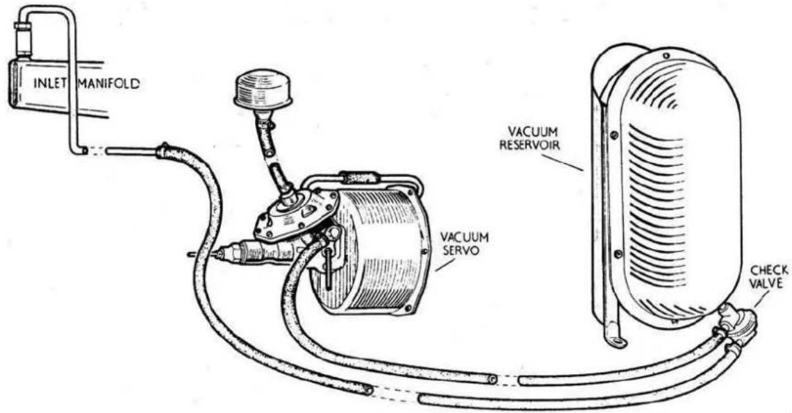
Fig.9.22. Layout of the servo mechanism
21 Vacuum reservoir and check valve description
The vacuum reservoir and check valve, which is inserted in the vacuum line between the inlet manifold and the servo unit, is located, together with a stone guard, in the front section of the right hand front road wheel arch. It provides a reserve of vacuum for assistance in braking if the engine stalls. The check valve is fitted in the bottom of the front face of the reservoir and its lower connection goes to the inlet manifold whilst the upper connection goes to the vacuum port of the servo unit.
Incorporated in the inlet port of the check valve is a rubber spring loaded valve which is drawn away from its seat when there is a depression in the inlet manifold thus exhausting the reservoir. When the depression in the reservoir equals that of the inlet manifold, the valve spring returns the valve to its seat and thus maintains vacuum in the reservoir.
22 Vacuum reservoir and check valve - removal and refitting
1 Jack up the front of the car and remove the right hand front
road wheel. Support the car on a firmly based axle stand.
2 Scrape all road dirt away from the reservoir.
3 Remove the three nuts and bolts and detach the reservoir and the stone guard from the wheel arch.
4 Undo one hose clip, remove the hose and clearly identify it.
5 Undo the other hose clip, remove the hose and identify this one.
6 Undo the four nuts and bolts securing the stone guard to the reservoir and remove it.
7 If necessary, unscrew the check valve from the bottom of the reservoir.
8 Refitting is the reverse of the removal procedure but make sure that the rubber hoses are fitted to the correct unions on the check valve, ie the hose from the servo unit connects to the check valve connector nearest to the screwed connection, this connector has two grooves in its body. The inlet manifold pipe goes to the bottom check valve union which has two annular ribs in its body.
23 Fault diagno is
| Symptom | Reason/s | Remedy |
| Brake travel excessive | Fluid level too low | Top up master cylinder reservoir and check for leaks |
| Wheel cylinder or caliper leaking | Dismantle wheel cylinder or caliper, clean, fit new rubbers and bleed brakes. | |
| Master cylinder leaking | Dismantle master cylinder, clean, fit new rubbers and bleed brakes. | |
| Brake flexible hose leaking | Examine and fit new hose. Bleed brakes. | |
| Brake line fractured | Replace with new pipe. Bleed brakes. | |
| Brake system unions loose | Check, tighten unions as necessary. Bleed brakes. | |
| Normal wear of linings | Fit replacement shoes or friction pads. | |
| Brake pedal feels springy | New linings not yet bedded in | Use brakes gently until springy feeling ceases. |
| Brake drums or discs badly worn, weak or cracked | Fit new brake drums or discs. | |
| Master cylinder securing nuts loose | Tighten nuts and make sure that spring washers are fitted. | |
| Brake pedal feels spongy and soggy | Wheel cylinder or caliper leaking | Dismantle wheel cylinder or caliper, clean, fit new rubbers and bleed brakes. |
| Master cylinder leaking | Dismantle master cylinder, clean, fit new rubbers and bleed brakes. | |
| Brake pipe line or flexible hose leaking | Fit new pipe line or hose. Bleed brakes. | |
| Unions in brake system loose | Examine for leaks and tighten. Bleed brakes. | |
| Brakes uneven and pulling to one side | Linings, drums or discs contaminated with oil or grease | Ascertain and rectify source. Clean drums and discs and fit new linings if necessary. |
| Tyre pressures incorrect | Check and rectify. | |
| Brake backplate or disc loose | Check and tighten as necessary. | |
| Brake shoes or pads fitted incorrectly | Remove and fit correct way round. | |
| Different types of lining fitted at each wheel | Fit linings of correct specification all round. | |
| Anchorages for front or rear suspension loose | Check and tighten as necessary. Ensure rubbers are not perished. | |
| Brake drums or discs badly worn craked or distorted | Fit new brake drums or discs. | |
| Brakes tend to bind, drag or lock-on | Incorrect adjustment of brake shoes or pads | Check and rectify shoe/pad adjustment mechanism |
| Handbrake cable over-tightened | Adjust correctly. | |
| Master cylinder by-pass port choked | Dismantle and clean master cylinder. Bleed brakes. | |
| Wheel cylinder piston seized | Dismantle and rectify wheel cylinder. Bleed brakes. | |
| Blockage of port through which air enters servo valve assembly | Remove and clean servo unit. Bleed brakes. | |
| Drum brake shoe pull-off springs weak, broken or loose | Examine springs and replace as necessary. | |
| Brakes fail to release | Handbrake over-adjusted | Check and adjust correctly |
| Master cylinder by-pass port choked | Dismantle master cylinder, clean and bleed brakes. | |
| Excessive friction between wheel cylinder seals and cylinder body | Dismantle wheel cylinder and rectify. Bleed brakes. |
Chapter 10 Electrical system and instruments
Contents
| General description | ... | ... | ... | ... | ... | ... | 1 |
| Battery - removal and replacement | ... | ... | ... | ... | ... | ... | 2 |
| Battery - maintenance and inspection | ... | ... | ... | ... | ... | ... | 3 |
| Battery - electrolyte replenishment | ... | ... | ... | ... | ... | ... | 4 |
| Battery charging | ... | ... | ... | ... | ... | ... | 5 |
| Dynamo - removal and refitting | ... | ... | ... | ... | ... | ... | 6 |
| Dynamo - dismantling | ... | ... | ... | ... | ... | ... | 7 |
| Dynamo - examination | ... | ... | ... | ... | ... | ... | 8 |
| Dynamo - reassembly | ... | ... | ... | ... | ... | ... | 9 |
| Dynamo - testing in position | ... | ... | ... | ... | ... | ... | 10 |
| Starter motor - description | ... | ... | ... | ... | ... | ... | 11 |
| Starter motor - removal and refitting | ... | ... | ... | ... | ... | ... | 12 |
| Starter motor - testing in position | ... | ... | ... | ... | ... | ... | 13 |
| Starter motor - dismantling and reassembly | ... | ... | ... | ... | ... | ... | 14 |
| Starter motor - examination test and rectification | ... | ... | ... | ... | ... | ... | 15 |
| Voltage and current regulator - general | ... | ... | ... | ... | ... | ... | 16 |
| Voltage regulator RB.106/1 and 106/2 - cleaning, checking and adjustment | ... | ... | ... | ... | ... | ... | 17 |
| Voltage and current regulator RB.310 - cleaning, checking and adjustment | ... | ... | ... | ... | ... | ... | 18 |
| Voltage and current regulator RB.340 - cleaning, checking and adjustment | ... | ... | ... | ... | ... | ... | 19 |
| Fuses - general | ... | ... | ... | ... | ... | ... | 20 |
| Flasher unit - general | ... | ... | ... | ... | ... | ... | 21 |
| Flasher unit - fault tracing and rectification | ... | ... | ... | ... | ... | ... | 22 |
| Windscreen wiper mechanism - fault diagnosis and rectification ... ... ... ... ... ... ... ... ... ... | 23 |
| Windscreen wiper mechanism - removal and refitting of wiper motor and cable ... ... ... ... ... ... ... ... | 24 |
| Windscreen wiper mechanism - removal and refitting of wheel boxes ... ... ... ... ... ... ... ... ... | 25 |
| Lighting equipment - removal, adjustment and refitting of components ... ... ... ... ... ... ... ... | 26 |
| Windscreen washer (electrical) - testing in position ... ... | 27 |
| Windscreen washer (electrical) - dismantling, testing and reassembling ... ... ... ... ... ... ... ... | 28 |
| Heater fan motor and fan switch - testing, removal and refitting ... ... ... ... ... ... ... ... ... | 29 |
| Horns and horn relay - fault tracing and rectification ... | 30 |
| Electric clock - removal and adjustment ... ... ... ... ... ... | 31 |
| Miscellaneous interior equipment and indicator lights - replacement of bulbs ... ... ... ... ... ... ... ... | 32 |
| Revolution counter AC generator - testing ... ... ... ... ... | 33 |
| The instrument panel - removal and refitting ... ... ... ... ... ... | 34 |
| The instrument panel components - removal and refitting ... | 35 |
| Speedometer and speedometer drive cable - removal and refitting ... ... ... ... ... ... ... ... ... | 36 |
| The revolution counter - removal and refitting ... ... ... ... ... ... ... | 37 |
| The bi-metal resistance instrumentation - fault finding ... | 38 |
| Wiring diagrams - colour coding ... ... ... ... ... ... | 39 |
Specifications
12 volt positive earth type
| Battery | |||||||
| Type | |||||||
| Mk 1 models and 2.4 litre Mk 2 | GT9A or GTZ9A for all models plus GTW9A for Mk 1 models and GTW9A/3 for 2.4 litre Mk 2 | ||||||
| Voltage | ... | ... | ... | ... | ... | ... | 12 |
| Number of plates per cell | 9 | ||||||
| Capacity (20 hour rate) | 58 ampere hour | ||||||
| Mk 2, 3.4 litre, 3.8 litre and 340 | |||||||
| Type | ... | ... | ... | ... | ... | ... | BV.11A |
| Voltage | ... | ... | ... | ... | ... | ... | 12 |
| Number of plates per cell | 11 | ||||||
| Capacity (20 hour rate) | 67 ampere hour | ||||||
| 240, also 2.4 litre Mk 2 (see above) | |||||||
| Type | ... | ... | ... | ... | ... | ... | $.9 |
| Voltage | ... | ... | ... | ... | ... | ... | 12 |
| Number of plates per cell | |||||||
| Capacity (20 hour rate) | 60 ampere hour | ||||||
Starter motor
| 2.4 litre all models and 240 | ... | ... | ... | ... | ... | Lucas M.418.G. |
| Lock torque ... | ... | ... | ... | ... | ... | 17 lb.f.ft. with 440–460 amps at 7.4–7 volts |
| Torque at 1000 rpm | ... | ... | ... | ... | ... | 8 lb.f.ft. with 250–270 amps at 9.4–9 volts |
| Light running current | ... | ... | ... | ... | ... | 45 amps at 7400–8500 rpm |
| 3.4 litre all models, 3.8 litre and 340 | ... | ... | ... | ... | ... | Lucas M.45.G |
| Lock torque ... | ... | ... | ... | ... | ... | 22 lb.f.ft. with 430–450 amps at 7.8–7.4 volts |
| Torque at 1000 rpm | ... | ... | ... | ... | ... | 8.3 lb.f.ft. with 200–220 amps at 10.2–9.8 volts |
| Light running current | ... | ... | ... | ... | ... | 45 amps at 5800–6800 rpm |
Dynamo
| 2.4 litre Mk 1 | ... | ... | ... | ... | ... | ... | ... | C.45 PV.5 |
| 3.4 litre Mk 1 | ... | ... | ... | ... | ... | ... | ... | C.45 PVS.5 |
| Performance data of the above:- | ||||||||
| Cutting in speed | ... | ... | ... | ... | ... | ... | ... | 1100-1250 rpm at 13.0 generator volts |
| Max: output | ... | ... | ... | ... | ... | ... | ... | 22 amp. at 1700-1900 rpm at 13.5 generator volts and a resistance load of 0.61 ohms |
| Field resistance | ... | ... | ... | ... | ... | ... | ... | 6.0 ohms |
| 2.4 litre Mk 2 and 240 | ... | ... | ... | ... | ... | ... | ... | C.45 PV.6, C.40L and C.42 (special order only) |
| Performance data:- | ||||||||
| Cutting in speed | ... | ... | ... | ... | ... | ... | ... | 1300 (max) rpm at 13 generator volts |
| Max: output | ... | ... | ... | ... | ... | ... | ... | 25 amps at 2050 rpm for type C.45 PV.625 amps at 2400 rpm for type C.40L30 amps at 2200 rpm for type C.42all at 13.5 generator volts and a resistance load of 0.54 ohms |
| Field resistance | ... | ... | ... | ... | ... | ... | ... | 6.0 ohms |
| 3.4 and 3.8 litre Mk 2 and 340 | ... | ... | ... | ... | ... | ... | ... | C.45 PVS6, C.42 and C.48 (special order only - high output) |
| Performance data:- | ... | ... | ... | ... | ... | ... | ... | Data for C.45 PV.6 given above also applies to the C.45 PVS6 generator.Data for C.42 generator given above. |
| Type C.48 | ||||||||
| Cutting in speed | ... | ... | ... | ... | ... | ... | ... | 850 (max) rpm at 13 generator volts |
| Max: output | 35 amps at 1650 (max) rpm at 13.5 generator volts and a resistance load of 0.385 ohms | |||||||
| Field resistance | ... | ... | ... | ... | ... | ... | ... | 6.0 ohms |
Windscreen wiper motor
| Type | ... | ... | ... | ... | ... | ... | ... | Lucas DR.3 two speed |
| Wiping speed: | ||||||||
| Normal | ... | ... | ... | ... | ... | ... | ... | 45–50 cycles per minute |
| High | ... | ... | ... | ... | ... | ... | ... | 60–70 cycles per minute |
| Light running current: | ||||||||
| Normal speed | ... | ... | ... | ... | ... | ... | ... | 2.7–3.4 amps |
| High speed | ... | ... | ... | ... | ... | ... | ... | 2.6 (or less) amps |
| Stall current | ... | ... | ... | ... | ... | ... | ... | 10–11 amps |
| Control switch | ... | ... | ... | ... | ... | ... | ... | 79.SA |
| Pressure of blades against windscreen:- | ||||||||
| Arms with leaf type springs | ... | ... | ... | ... | ... | 4.5–7.5 ounces | ||
| Arms with coil type springs | ... | ... | ... | ... | ... | 5.5–7.5 ounces | ||
| Maximum permissible force to move cable rack in protective tubing with motor, arms and blades disconnected | ... | ... | 6.0 lbs | |||||
Replacement bulbs (all 12 volt)
| LampHeadlight | ... | ... | ... | ... | ... | ... | ... | ... | WattsSealed beam units for UK (240 and drive export60/36 | Lucas No:404 | RemarksLarge globe |
| Side light | ) | ||||||||||
| Map light | ) | ||||||||||
| Pillar interior light | ) | ... | ... | ... | ... | ... | ... | ... | 6 | 989 | No.222 can be used |
| Number plate | ) | ||||||||||
| Luggage boot light | ) |
| Front and rear | ) | ||||||||
| Flashing indicators | ) | ... | ... | ... | ... | ... | ... | 21 | 382 |
| Reversing light | ) | ||||||||
| Rear/brake light | ... | ... | ... | ... | ... | ... | ... | 21/6 | 380 |
| Fog lights | ... | ... | ... | ... | ... | ... | ... | 48 | 323 |
| Rear interior light | ... | ... | ... | ... | ... | ... | ... | 6 | 254 |
| Instrument illumination | ) | ||||||||
| Headlamp warning light | ) | ||||||||
| Ignition warning light | ) | ... | ... | ... | ... | ... | ... | 2.2 | 987 |
| Fuel warning light | ) | ||||||||
| Handbrake/brake fluid warning light | ) | ||||||||
| Switch indicator strip | ) | ||||||||
| Flashing indicator warning light | ) | ||||||||
| Overdrive indicator light | ) | ... | ... | ... | ... | ... | ... | 1.6 | 281 sub-miniature |
| Auto-trans: indicator light | ) |
1 General description
All models have 12 volt electrical systems in which the positive battery terminal is earthed.
The major components of the system are a 12 volt battery located at the top right hand side of the engine bulkhead, a dynamo mounted on the engine at the front left hand side, a starter motor at the rear right hand side of the engine and a current and voltage regulator on the left hand valance in the engine compartment.
The battery supplies a steady amount of current for the ignition, lighting and other electrical circuits, and provides a reserve of electricity when the current consumed by the electrical equipment exceeds that being produced by the dynamo.
The battery is charged by one of the various types of dynamo enumerated under Specifications at the beginning of this Chapter. The main external difference in the various types of dynamo is that whereas the connections to the earlier types were secured by nuts, the later types use Lucar connectors.
Although full instructions for the periodic overhaul and minor servicing of the various electrical components are given in this Chapter it must be appreciated that rectification of major faults will require specialised knowledge and equipment and so, where such faults arise, the defective item should be removed and replaced with a serviceable item which can be obtained on an exchange basis.
Wiring diagrams covering the various models are given at Figs 10.50, 10.51, 10.52 and 10.53.
2 Battery - removal and replacement
1 Mark the position of the bonnet hinges relative to the bonnet. With the help of an assistant to support the bonnet, remove the four bolts securing it to the hinges and then lift the bonnet forward off the car and store it where it will not be damaged.
2 Remove the battery cover by springing back the two clips.
3 Remove the securing screw attaching each terminal to its lug on the battery or, if applicable, undo each terminal clamping nut and bolt.
4 Remove the two bolts (one each side of the battery) which hold the battery retaining band and remove the band and the rubber packing.
5 Lift out the battery from the tray.
6 However, it is possible to remove the battery without taking off the bonnet provided you are strong enough to lift the heavy battery clear of the car. Proceed as outlined in paragraphs 2-4 above, use a stubby screwdriver to undo the terminal screws. Now tilt the battery forward but do not tilt so far as may cause spillage of the electrolyte; put your left hand underneath the lip on the top of the battery and your right hand under the battery.
Lift the battery upwards and outwards, you will find that this is made awkward by restriction of access due to the bonnet. Make sure that you do not drop the battery as soon as it is clear of the tray as damage to the clutch and brake master cylinders and pipes will result.
7 Replacement is the reverse of the removal procedure in each case but before refitting the terminals clean them and then coat them with vaseline to prevent corrosion; DO NOT use an ordinary grease.
3 Battery - maintenance and inspection
Note: Never use a naked light when examining a battery as an explosive mixture of oxygen and hydrogen is given off when it is on charge or when standing idle.
1 Normal weekly battery maintenance consists of checking the level of the electrolyte in the cells to ensure that the separators are covered by about 14 " of electrolyte. If the level has fallen, top up with distilled water only. Do not overfill the battery. If the battery is overfilled or any electrolyte is spilled, clean it away immediately as the electrolyte is extremely corrosive.
2 Keep the terminals clean and covered with petroleum jelly.
3 Clean the top of the battery regularly. Maintaining it in a clean and dry condition will help to prevent corrosion and will also ensure that the battery does not become partially discharged by leakage through dampness and dirt.
4 Inspect the battery securing nuts, the clamp plate, the tray and leads for corrosion which will show up as white fluffy deposits brittle to the touch. If corrosion is found, clean it off with ammonia and then paint over the clean metal with an anti-rust, anti-acid paint.
5 Inspect the battery case for cracks. If a crack is found, clean and plug it with one of the propriety compounds now on the market. If leakage through the crack has been excessive it will be necessary to refill the cell concerned with fresh electrolyte. Cracks are commonly caused at the top of the battery case by pouring in distilled water in the middle of winter AFTER instead of BEFORE a run. This gives the water no chabce To mix with the electrolyte and so it freezes and splits the battery case.
6 If very frequent topping up is necessary and it has been established that the case is not cracked, the fault is due to overcharging of the battery and indicates a need to check and reset the voltage regulator. (Refer to Sections 17, 18 or 19 as applicable).
7 If the battery persists in a low state of charge, first consider the conditions under which the battery is used. If it is subjected to long periods of discharge without suitable opportunities for recharging, a low state of charge must be expected. If, on the other hand, the battery remains in a low state of charge when the car is in regular use with reasonably long running periods each day then it may be that the dynamo or the voltage regulator are at fault. A heavy discharge tester can be used to determine whether or not the fault lies in the battery. Your local
garage can easily carry out the test for you but the battery will have to be removed for the test because the car bonnet will prevent access for the tester to the battery terminals. The contact prongs of the tester are pressed against the exposed positive and negative terminals of each cell. A good cell will maintain a reading of 1.2-1.5 volts for at least six seconds. If, however, the reading falls off rapidly that particular cell is probably faulty and will especially if other cells are also at fault, account for the low state of charge of the battery.
8 The specific gravity of the electrolyte in each cell should be checked periodically using a hydrometer but to avoid misleading readings do not take hydrometer readings immediately after Topping up with distilled water. The readings given by each cell should be approximately the same and if one cell differs appreciably from the others, an internal fault in that cell is indicated.
9 The appearance of the electrolyte drawn into the hydrometer will give an indication of the state of the plates. If the electrolyte is very dirty or contains small particles in suspension, it is possible that the plates are in poor condition.
10 The specific gravity of the electrolyte varies with its temperature and so, for convenience in comparing specific gravities, this is always corrected to 60° F. The method of correction is as follows:-
For every 5°F below 60°F deduct 0.002 from the hydrometer reading to obtain the correct specific gravity at 60°F.
For every 5^ F above 60^ F add 0.002 to the hydrometer reading.
11 The specific gravity of electrolyte corrected to 60^ F is given in the following table:-
| State of charge | U.K. and climates ordinarily below 90^ F( 32.2^ C) .Specific gravity corrected to 60^ F | Climates frequently over 90^ F ( 32.2^ C )Specific gravity corrected to 60^ F |
| Fully charged | 1.270 – 1.290 | 1.210 – 1.230 |
| About half charged | 1.190 – 1.210 | 1.120 – 1.150 |
| Completely discharged | 1.110 – 1.130 | 1.050 – 1.070 |
4 Battery - electrolyte replenishment
1 If the battery is in a fully charged state and one of the cells maintains a specific gravity reading lower than the others and a check of each cell has been made with a discharge tester with satisfactory results, then it is likely that at some time electrolyte has been lost from the cell.
2 Top up the cell with a solution of 1 part sulphuric acid to 2.5 parts water. If the cell is already fully topped up, draw some electrolyte out of it with a pipette.
3 When mixing sulphuric acid and water NEVER ADD WATER TO THE ACID. Always pour the acid slowly onto the water in a glass container. IF WATER IS ADDED TO THE SULPHURIC ACID IT WILL EXPLODE.
4 Recharge the battery after topping up with the electrolyte and recheck hydrometer readings.
5 Battery charging
1 In winter time when a heavy demand is placed on the battery it is a good idea to have the battery charged occasionally from an external source at a rate of 5 amps. Alternatively, a trickle charger, charging at the rate of 1.5 amps can be safely used overnight. Special rapid boost charges which are claimed to restore the power of the battery in 1 to 2 hours are most dangerous unless they are thermostatically controlled as they can cause damage to the battery plates through overheating.
6 Dynamo - removal and refitting
1 For cars fitted with power steering, first disconnect the pipes to the pump at the rear of the dynamo and then drain the hydraulic system as described in Chapter 11. Proceed as follows to remove the dynamo and pump as one system.
2 Disconnect the cables from the Lucar connectors, or by undoing he securing nuts as appropriate, at the rear of the dynamo, noting that the terminals are of different sizes.
3 Remove the nut and bolt securing the adjusting link to the dynamo.
4 Remove the two nuts and bolts, one at the front and one at the rear, which secure the dynamo to the mounting bracket.
5 Tilt the dynamo to assist in removing the fan belt from the pulley and then lift the dynamo out of the car.
6 Refitting is the reverse of the removal procedure. Before final tightening of the securing bolts, position the dynamo so that it is possible to depress the belt about 12 " (12 mm) at a point midway between the fan and dynamo pulleys.
7 On cars fitted with power steering, refer to Chapter 11 for procedures for refitment of the hydraulic pipes, refilling and bleeding the hydraulic system.
7 Dynamo - dismantling
1 The main difference between both types of dynamo is that the porous bronze bearing ring bush of the early type is replaced by a ball race. In addition the yoke of the later type is provided with 'windows' to enable examination of the brush gear without dismantling the dynamo. The 'windows' are covered with a steel band secured by a nut and bolt.
2 Remove the nut securing the driving pulley. Take off the pulley and collect the Woodruff key from the shaft.
3 Unscrew and remove the two through bolts.
4 Take off the commutator end bracket from the yoke.
5 Remove the driving end bracket complete with the armature.
6 Lift the brush springs to one side and draw the brushes out of the brush holders, note their position for refitment if they are not being renewed. Undo the screws and lock washers holding the brush leads to the commutator end bracket and remove the brushes.
7 The bearings need not be removed, or the armature shaft separated from the driving end bracket unless the bearings or the armature are to be renewed. If the items are to be separated, support the driving end bracket and press out the shaft by means of a hand press.
8 Dynamo - examination
1 Fit the brushes to their respective holders and check them for freedom of movement. If movement is sluggish, remove them and ease the sides by lightly polishing with a smooth file.
2 Measure the length of the brushes, the minimum permissible length is 11/16" and brushes not meeting this must be renewed and bedded to the commutator.
3 Fit the commutator end bracket over the commutator, fit the brushes in their holders and, using a spring balance, test the brush spring tension. The tension of a new spring and new brush is 28 ozs and the minimum permissible tension for correct operation is 20 ozs. Renew any brush spring when the tension falls below that value. It should be noted that it is possible to examine the brushes and to check the spring tension without dismantling the later type of dynamo as this work can be done through the 'window' (see Fig10.3).
4 Clean the commutator with a petrol moistened cloth. A commutator in good condition will be smooth and free from pits or burned spots. Minor blemishes can be removed by polishing the commutator with fine glass paper whilst rotating the armature. It may be possible to rectify a badly worn commutator by mounting the armature in a lathe and taking a light cut with a very sharp tool at a high speed. But do not remove
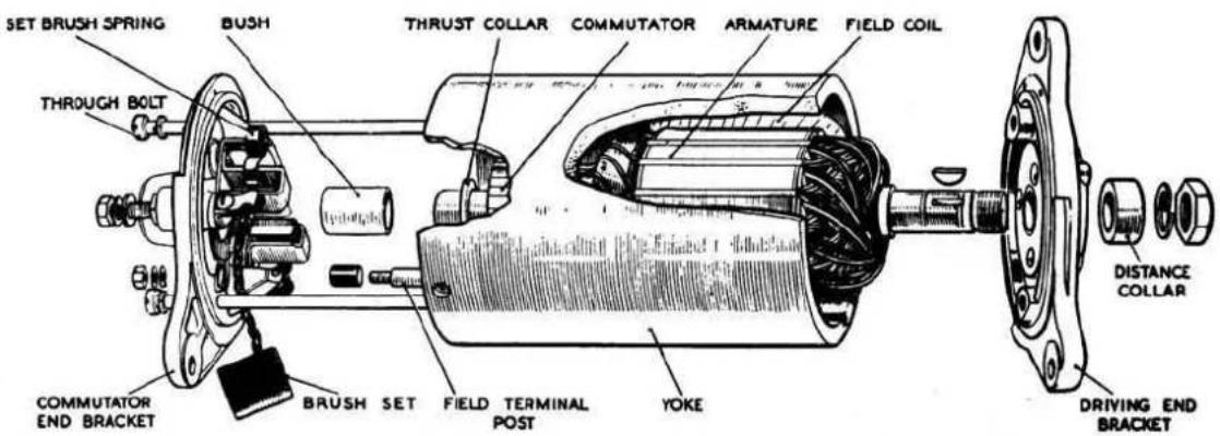
Fig.10.1. The dynamo (early type)

Fig.10.2. Dynamo (later type) commutator end bracket removed
more metal than absolutely necessary.
After working in the lathe, polish the commutator with fine glass paper. Now undercut the insulators between the segments to a depth of 1/32" as illustrated in Figs10.4. A hacksaw blade ground to the thickness of the insulator is a handy tool for undercutting but make sure that the insulator is cut away squarely and cleanly as shown in Fig.10.5.
5 Burnt commutator segments are indicative of an open circuited armature winding. If you have no armature testing facilities the only way it can be checked is by substitution.
6 The old armature is removed from the driving end bracket in the manner described in Section 7.
7 It is essential, when fitting the new armature, that the inner journal of the ball race is supported by a piece of mild steel tube of suitable diameter.
8 The resistance of the field coils can be checked without removing them from the yoke by using an ohmmeter connected between the field terminal and the yoke. The field resistance is 6.0 ohms. If a meter is not available, the field coils can be checked by connecting a 12 volt battery between the field terminal and the yoke with an ammeter in series.
9 The ammeter reading should be about 2 amperes, if a zero reading or 'infinity' on the ohmmeter is recorded, an open circuit in the field winding is indicated. If the current reading is above 2 amps or the meter reading is lower than 6 ohms it means that the insulation of one of the coils has broken down.
10 Replacement of the field coils involves the use of equipment not normally available to most home mechanics so our recommendation is that in the event of field coil failure, you obtain a replacement exchange dynamo.
11 Check the condition of the bearings. They must be changed when wear has reached the point of allowing visible side movement of the armature shaft. A bush bearing is fitted to the commutator end bracket and a ball bearing at the drive end bracket of the earlier type of dynamo, whilst later types have a
ball race at each end.
12 To change a bearing bush, first obtain a replacement and then allow it to soak for 24 hours immersed in thin engine oil so that the pores of the brush are filled with lubricant.
13 Remove the old bearing bush from the commutator end bracket using an extractor or by screwing an 11/16" tap into the bush for a few turns and then using the tap as an extractor but make sure that the tap is screwed in squarely to avoid damage to the bracket and that side loads are not applied when pulling out the bush.
14 Examine the felt ring in the bearing housing and if it is in good condition it can be re-used.
15 Replace the felt ring and then press the new bearing bush into the housing using a shouldered and highly polished mandrel of the same diameter as the armature shaft. Press in the bush until the end is flush with the inner face of the bracket.
16 To replace the ball race at the driving end, refer to Fig.10.7 and drill out the rivets which secure the retaining plate to the end bracket and then remove the plate.
17 Press the bearing out of the end bracket and collect the corrugated washer, the felt washer and the oil retaining washer. 18 Pack the new bearing with high melting point grease.
19 Refit the oil retaining washer, the felt washer and the corrugated washer to the bearing housing in that order and then locate the bearing in the housing and press it home.
20 Assemble the bearing retaining plate and insert new rivets from the inside of the end bracket and then open them out with a punch to secure the plate.
21 The ball race fitted at the commutator end of the armature shaft as illustrated in Fig.10.2 is secured to the shaft by a thrust screw. The bearing can be removed with an extractor after the thrust screw has been removed. When fitting a new bearing, first pack it with high melting point grease and then press it home against the shoulder on the shaft and finally secure it with the thrust screw.

natural_image
Technical line drawing of a sewing machine needle stitching fabric (no text or symbols)Fig.10.3. Checking the tension of the brush spring

natural_image
Illustration of hands using a commutator insulator to cut the shaft (no text or symbols present)9 Dynamo - reassembly
1 Fit the drive end bracket to the armature shaft and during this operation the inner journal of the race in the bracket must be supported. A piece of tube 4" in length and 1/8" thick and 11/16" internal diameter will be found suitable for this. The drive end bracket itself must not be used as a support.
2 Place the yoke over the armature to mate with the drive end bracket.
3 Assemble the brushes to the same brush holders from which they were removed (unless new brushes are being fitted) and secure their leads to the terminals with the screw and shakeproof washer. Lift up the brush springs and place them to one side so that they are not bearing on the brushes.
4 Make sure the brushes are clear of the commutator end of the holders and then fit the commutator end bracket to the armature shaft until the brush holders are partly over the commutator. Release the brush springs and then slide the commutator end bracket home against the yoke so that the projection on the bracket locates in the yoke.
5 After making sure that the mounting holes in the commutator end and the driving end brackets are correctly aligned,

Fig.10.5. Correctly and incorrectly cut insulators
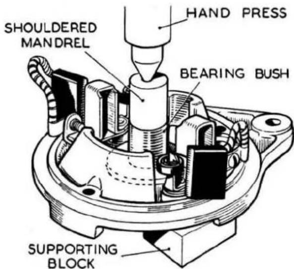
Fig.10.6. Fitting a bearing bush
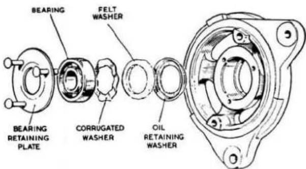
Fig.10.7. The drive end bracket bearing assembly
refit the two through bolts and tighten down.
6 Lubricate the commutator end bearing (bush type) by injecting a few drops of medium engine oil into the hole marked "oil" at the end of the bearing housing (Fig.10.8).
10 Dynamo - testing in position
1 If it is noted, from ammeter readings during normal running, that there is no charge or low or intermittent charge, proceed as follows to determine the cause of the fault.
2 Check the fan belt and adjust as necessary.
3 If the dynamo or control box connections have been upset, check that they are connected correctly. The large and the small dynamo terminals should be connected to control box terminais "D" and "F" respectively.
4 Next switch off all lights and accessories (do not forget the

Fig.10.8. Lubricating the bush bearing
rear window heater if this is fitted and is connected to operate when the ignition is switched "ON"), disconnect the cables from the dynamo terminals and connect the two terminals with a short length of wire.
5 Start the engine and allow it to run at normal idling speed. Now attach the negative lead of a 0.20 volt moving coil voltmeter to one dynamo terminal and the positive lead to a good earth on the yoke.
6 Gradually increase engine speed and note the reading of the voltmeter which should rise rapidly and without fluctuation. Do not allow the reading to reach 20 volts and do not race the engine in an attempt to increase the voltage. A generator speed of about 1000 rpm is all that is required.
7 If the voltage does not rise rapidly and without fluctuation, an internal fault is indicated and the dynamo will have to be removed for detailed examination and test as indicated in Section 8 but before doing this, if a radio suppressor is fitted between the output terminal of the dynamo and earth, disconnect it and re-test the dynamo. If readings are now satisfactory, the capacitor is the cause of the fault.
11 Starter motor - description
The starter motor uses a series wound, four pole and four brush system which has an extended shaft carrying the starter drive. It is of similar construction to the dynamo except that heavier gauge copper wire is used in the windings of the armature and field coils.
12 Starter motor - removal and refitting
1 Disconnect the battery.
2 Place the car over a pit or raise the front to give access to the terminal connection. Make sure that the car is well supported before doing any work underneath it.
3 Disconnect the cable from the terminal at the end of the motor.
4 Working from inside the car, move both seats to the rear as far as they will go and then remove the seat cushions. Slacken the gear lever knob locknut and remove the gear lever knob.
5 Unscrew the chrome knob securing panel assembly between the two seats, lift the rear of the panel upwards and rearwards to remove it.
6 Undo the two thumb screws and remove the trim panel from the right hand side of the gearbox cover.
7 Detach the right hand heater hose from the distributor box and you will see a circular plate in the floor, remove the plate to gain access to the nut of the top bolt securing the starter motor. Remove the nut but leave the bolt in position.
8 Working from underneath the car, remove the nut from the bottom bolt.
9 Support the starter motor and withdraw both bolts (they are connected by a curved metal rod). Now withdraw the starter motor.
10 Refitting is the reverse of the removal procedure.
13 Starter motor - testing in position
1 Switch on the lights and the ignition, ensure that the gear selector lever on automatic transmission models is in "N" or "p"

2 Operate the starter control, if the lights go dim but the motor is not heard to operate, it shows that current is flowing through the motor windings but that, for some reason, the armature is not rotating. It may be that the pinion has not disengaged from the starter ring on the flywheel in which case the motor will have to be removed from the car for examination.
3 If, when the starter is operated, the lamps retain their full brilliance and the motor does not operate, check the circuit for continuity starting with the battery connections (especially the earth connection), then look carefully at the engine earth connection followed by the connectios to the motor and the starter switch. If it is established that voltage is getting to the motor when the switch is operated, an internal fault in the motor is indicated.
4 Sluggish or a slow action of the motor is usually caused by a loose connection resulting in high resistance in the circuit, check as described in paragraph 3.
5 If the motor is heard to operate but it does not turn the engine, a fault in the drive is indicated which will involve removal of the motor for rectification.
14 Starter motor - dismantling and reassembly
1 Before completely dismantling the motor to check for a fault, first make sure that the brushes are not the cause of the trouble. This can be done by slackening the nut and bolt securing the "window" cover band, slide the band clear of the 'windows' and the brushes can now be lifted out for examination. It is also possible to check the weight of the brush spring (correct tension 30-40 ozs) using a spring balance through the window.
2 Leave the brushes out of their holders if they are satisfactory and further dismantling is necessary.
3 Remove the nuts from the terminal post at the commutator end bracket.
4 Unscrew the two through bolts, and making sure that the brushes do not foul the yoke, remove the commutator end bracket from the yoke.
5 Relate the brushes, if they are serviceable, to their respective holders and then undo the lead securing screws and remove the brushes.
6 Withdraw the driving end bracket, complete with the armature and drive, from the yoke.
7 Now refer to Fig.10.11 for dismantling of the drive.
8 Take out the split pin from the shaft nut (B), hold the squared end of the shaft with a spanner and then unscrew the nut.
9 Take off the main spring (C) followed by the remainder of the components.
10 Reassembly of the starter motor and drive is a reversal of the above procedure.
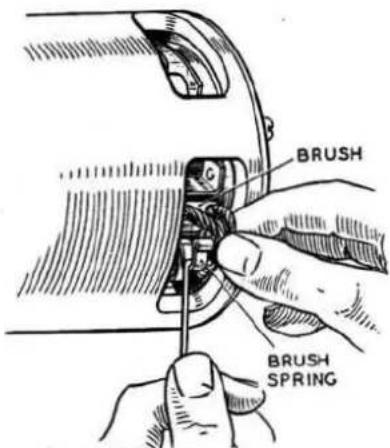
Fig.10.10. Checking the brush gear
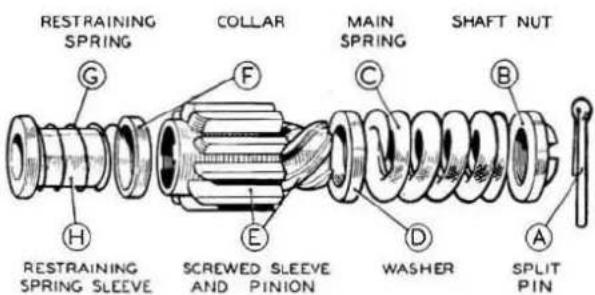
Fig.10.11. The starter drive
15 Starter motor - examination, test and rectification
1 Except for the following points, follow the instructions given for the dynamo in Section 8:-
a) The minimum permissible length of the brushes is 5/16".
b) The acceptable tension of the brush springs is 30-40 ozs.
c) The insulators between the commutator segments MUST NOT BE UNDERCUT.
d) No attempt should be made to machine the armature core or to true a distorted armature shaft.
e) If either the screwed sleeve or the pinion of the drive are worn or damaged, they must be replaced as a pair, not separately.
16 Voltage and current regulator - general
Early Mk.1, 2.4 litre cars are fitted with an RB 106/1 or RB 106/2 unit having a voltage regulator and cut-out. The RB 310 voltage and current regulator is fitted to later 2.4 litre and all 3.4 litre Mk 1 cars and early Mk 2 models. All later models use the RB 340 control box. RB 310 and RB 340 control boxes readily identifiable by their covers which, in the case of the former is an aluminium pressing and a moulded black plastic for the latter.
Only a good quality MOVING COIL VOLTMETER (0-20 volts) must be used when carrying out any of the continuity checks enumerated in the following Sections.
17 Voltage regulator RB 106/1 and 106/2 - cleaning, checking and adjustment
1 If it is found necessary to clean the regulator contacts, this can be done with a fine carborundum stone or fine emery cloth. The cut-out contacts should be cleaned with fine glass paper. All traces of metal dust or foreign matter must be removed after cleaning by use of a clean cloth and methylated spirits.
2 To check continuity between the battery and the control box first disconnect the cable from the control box terminal 'A' and connect the cable to the negative terminal of the voltmeter. Connect the positive terminal of the voltmeter to a good earth on the chassis and a reading of 12 volts (battery voltage) should be obtained. If there is no reading, a fault in the wiring is indicated and this should be checked for defects or loose connections. Reconnect the cable to terminal "A" of the control box on completion of the check.
3 The regulator is carefully set during manufacture and normally no adjustment is necessary in service but if the battery does not keep in a charged condition or if the dynamo output does not fall when the battery is fully charged, the setting must be checked and adjusted. However, first make sure that the trouble is not due to causes such as a slipping fan belt or a defective battery.
4 Disconnect the cables at terminals "A" and "A1" at the control box and connect these cables together. Now connect the
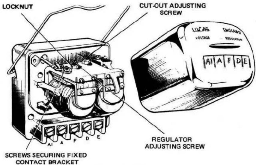
Fig.10.12. The RB.106/1 control box

Fig.10.13. The RB.106/2 control box
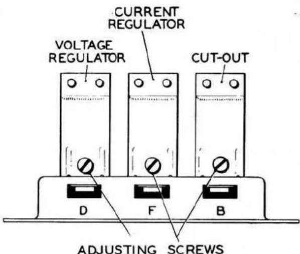
Fig.10.14. The RB.310 control box showing location of adjusting screws

FIG.10.15. CIRCUIT DIAGRAM OF RB.340 CONTROL BOX

FIG.10.16. THE UNDERSIDE OF THE RB.340 CONTROL BOX
1 Field
2 Cut-out relay
3 Current regulator
4 Swamp resistor
5 Field resistor
6 Voltage regulator
7 Armature
8 Generator
1 Battery main-terminal
2 Swamp resistor
3 Ballast resistors
4 Field resistors
voltmeter to terminals "D" and "E" of the control box.
5 In order to obtain accurate readings, the air temperature in the vicinity of the control box should be known as indicated in the table given below. Any adjustment found necessary should be completed within 30 seconds because heating of the shunt coil by the energising current may cause false settings to be made.
6 Start the engine and run up to 2100 rpm when the open circuit voltage reading should be within the following limits:-
| Regulator Temperature | Voltage Setting |
| 50^ ( 10^ ) | 16.1 – 16.7 |
| 68^ ( 20^ ) | 16.0 – 16.6 |
| 86^ ( 30^ ) | 15.9 – 16.5 |
| 104^ ( 40^ ) | 15.8 – 16.4 |
7 If the voltmeter reading is outside the limits quoted above, slacken the locknut of the voltage adjusting screw and turn the screw clockwise to raise the setting and anti-clockwise to lower it until the correct setting is obtained.
8 Retighten the locknut.
9 If, despite the fact that the regulator is correctly set and the contacts are clean, the battery is still not being charged in may be that the cut-out requires adjustment.
10 Connect the voltmeter between terminals "D" and "E" of the control box. Start the engine and slowly increase its speed until the cut-out contacts are seen to close; note the voltage recorded at this point. The cut-out contacts should have closed at between 12.7 and 13.3 volts and if this is not achieved, slacken the locknut securing the cut-out adjusting screw and turn the screw clockwise to increase the voltage and anti-clockwise to reduce it. Turn the screw only a fraction of a turn at a time and then tigh on the locknut. Recheck, after each adjustment, on the voltage at which the cut-out contacts close. These checks, as with adjustment of the regulator, must be done as quickly as possible to avoid errors due to rises in temperature.
18 Voltage and current regulator RB 310 - cleaning, checking and adjustment
1 Clean the regulator and cut-out contacts in the manner described in Section 17.
2 Check continuity between the battery and the control box in the manner described in Section 17 except that in this case the negative terminal of the voltmeter is connected to control box terminal "B".
3 To adjust the voltage regulator, disconnect the cable from control box terminal "B" and connect the voltmeter to control box terminal "D" and a good earthing point. Now carry on as set out in paragraphs 5 and 6 of Section 17, the open circuit voltage for this model regulator should lie within the following limits:-
| Regulator Temperature | Voltage Setting |
| 50^ ( 10^ ) | 15.1 – 15.7 |
| 68^ ( 20^ ) | 14.9 – 15.5 |
| 86^ ( 30^ ) | 14.7 – 15.3 |
| 104^ ( 40^ ) | 14.5 – 15.1 |
4 If the reading is outside the above limits, refer to Fig.10.14 and rotate the adjusting screw, which is adjacent to the "D" terminal, clockwise to increase and anti-clockwise to decrease the setting.
5 To adjust the current regulator it is necessary that the dynamo develops its full rated output and so the voltage regulator must be made inoperative, this is done by short circuiting the regulator contacts with a crocodile clip placed between the insulated fixed contact bracket and the voltage regulator frame.
6 Now disconnect the cable from terminal "B" and connect a first grade 0-14 amp moving coil ammeter between this cable and terminal "B".
7 Start the engine and run it at about 2700 rpm; the ammeter reading should be 24-26 amps. If this reading is not obtained, adjust on the centre adjusting screw depicted in Fig.10.14, screw clockwise to increase and anti-clockwise to decrease the setting.
8 Carry out a final check by stopping the engine, restarting and
again running at 2700 rpm to make any further adjustment as may be necessary.
9 Remove the ammeter and restore the original connections.
10 The cut-out is adjusted in exactly the same manner as described in paragraph 10 of Section 17. It must be noted that the cut-out adjustment screw is that shown on the extreme right in Fig.10.14 adjacent to terminal "B".
19 Voltage and current regulator RB 340 - cleaning, checking and adjustment
1 The regulator and the cut-out relay contacts are cleaned in the same manner as the other types of regulator.
2 First check what pattern dynamo is fitted as the test methods are not the same for all types. You will find the type and serial number of the dynamo stamped on the upper part of the yoke.
3 Open circuit settings for the various types of dynamo normally used in conjunction with the RB 340 regulator are given below.
| Regulator Temperature | Voltage | |
| C.40-C42 dynamo | C.48 dynamo | |
| 10^ ( 50^ ) | 14.9-15.5 | 15.0-15.6 |
| 20^ ( 68^ ) | 14.7-15.3 | 14.8-15.4 |
| 30^ ( 86^ ) | 14.5-15.1 | 14.6-15.2 |
| 40^ ( 104^ ) | 14.3-14.9 | 14.4-15.0 |
4 To check the open circuit voltage (do the work as quickly as possible to avoid errors due to heating of the coil) first take off the cable from terminal "B" at the control box.
5 Connect a voltmeter between terminal "D" of the box and a good earth. It may be more convenient to take off the ignition warning light feed from terminal "WL" and to use the blade of that terminal which is electrically common with terminal "D" (see Fig.10.17).
6 Start the engine and run it at 1800 rpm for C.40L and C.48 dynamos and at 2700 rpm for C.42. Check the voltmeter which should be steady and lie between the limits quoted in paragraph
- An instead reading may be due to dirty contacts which should be checked and cleaned. If the reading is steady but outside limits, the regulator, all other factors being satisfactory, will have to be adjusted.
7 Remove the cover of the control box if you have not already done so and, with the engine running at the speeds quoted in paragraph 6, turn the voltage adjustments cam (Fig.10.18) until the correct setting is obtained. Clockwise rotation of the screw will increase and anti-clockwise rotation will decrease the voltage. A special tool, which engages in the serrations of the adjustment cams, is used for turning the cams and this you may be able to borrow from your local garage.
8 Check your settings by stopping the engine, re-start it and carry out a check at the speed required for your dynamo. If readings are now satisfactory, remake the original connections and refit the cover.
9 The "on load" setting for the regulator is equal to the maximum rated output of the dynamo which for the C.42 is 30 amps, for the C.48 35 amps and for the C.40L 25 amps. So, to check the "on load" setting, the dynamo must be made to develop its maximum rated output and this is done by shorting out the voltage regulator, Fig.10.19 shows a bulldog clip being used for this purpose.
10 Now withdraw the cable from terminal "B" and connect the cable to the load side of a first grade 0-40a moving coil ammeter and then connect the other side of the ammeter to one of the control box terminal blades "B". Make sure that terminal "B" carries only this one connection, all other load connections must be made to the battery side of the ammeter.
11 Switch on all lights, this will ensure that the generator does indeed develop its full output.
12 Start the engine and run it at 2700 rpm for the C.42 dynamo and at 1800 rpm for the C.40L and C.48 dynamos. Watch the
ammeter needle which should be steady and should indicate a current equal to the maximum rated output of the dynamo quoted in paragraph 9. Fluctuations of the needle in excess of ±1 amp indicates dirty contacts which should be rectified.
13 If readings are too high or too low, adjust on the cam until the correct settings are obtained. Clockwise rotation of the cam will increase and anti-clockwise rotation will decrease the setting. 14 When the reading is satisfactory, switch off the engine and remake the original connections.
15 The electrical settings of the cut-out relay are:-
Cut-in voltage
12.6 - 13.4
Drop-off voltage
9.3 - 11.2
16 To check the above settings, connect a voltmeter between the control box terminal "D" and a good earthing point but, as in the case when adjusting the open circuit settings, terminal "WL" (Fig.10.20) may be used if desired (see paragraph 5).
17 Start the engine, switch on the headlamps and slowly increase engine speed at the same time watching the voltmeter. The voltage should rise steadily and then drop slightly at the moment the contacts close. The cut-in voltage is that which is recorded immediately before the drop back and should be within the limits given in paragraph 15. If the cut-in voltage is outside the limits quoted, adjustment is necessary.
18 Reduce the speed of the engine (dynamo) to below cut-in value, take off the cover of the control box and turn the cut-out relay adjustment cam a small amount in a clockwise direction to increase the setting and in an anti-clockwise to reduce it. Carry on adjusting and checking as instructed in paragraph 17 until the correct setting is obtained.
19 Remake the connections and replace the cover.
20 To check drop-off settings, disconnect the cable from terminal "B" at the box and connect a voltmeter between terminal "B" and earth.
20 Start the engine and run up to about 1800 rpm, slowly decelerate and observe the point at which the voltmeter suddenly records a zero reading which indicates the opening of the contacts. An adjustment must be made if the reading is
outside the limits given in paragraph 15.
21 Stop the engine and remove the cover of the control box. Now very carefully bend the fixed contact bracket, reducing the gap will increase the drop-off voltage and increasing the gap will lower it.
22 Repeat the test and readjust until the correct setting is obtained. The resulting blade deflection should be in the region of 0.010 - 0.035" (0.25 - 0.80 mm).
23 Remake the original connections and replace the cover of the box.
24 The air gap settings are accurately adjusted during manufacture and should require no further attention during the life of the control box. However, if the original settings have been disturbed they must be reset as follows.
25 To set the core gaps of the voltage and current regulators, refer to Fig.10.21 and, using a suitable tool, turn the adjustment cam (A) fully anti-clockwise and now slacken the adjustable contact locking nut and screw back the adjustment contact.
26 Taking care not to turn up or damage the copper shim, insert a 0.052 - 0.056" (1.3 - 1.4 mm) feeler gauge between the armature and the copper separation on the core face. The gauge should be inserted as far back as the two rivet heads on the underside of the armature.
27 Hold the feeler gauge in position and press down squarely on the armature, now screw in the adjustable contact until it just touches the armature contact. Retighten the locking nut and then take out the gauge.
28 Carry out the electrical setting procedure as previously described.
29 To adjust the contact "follow through" and armature-to-bobbin core gap of the cut-out relay, refer to Fig.10.22.
30 Press the armature down squarely against the copper separation on the core face.
31 Adjust the fixed contact bracket to give a "follow through" (or blade deflection) of the moving contact of 0.010 - 0.035" (0.25 - 0.89 mm). Release the armature.
32 Adjust the armature back stop to give a core gap of 0.035 - 0.045" (0.89 - 1.14 mm).
33 Now check the cut-in and drop-off voltage settings as described in paragraphs 15-23.

Fig.10.17. RB.340 control box. Checking open circuit setting

FIG.10.18, RB.340 CONTROL BOX ADJUSTING THE CAMS
1 Bulldog clip
2 V.R. contacts
3 Voltage regulator
4 Current regulator
5 Cut-out relay
6 Setting tool
7 Adjustment cams

Fig.10.19. RB.340 control box. Checking the 'on-load' setting
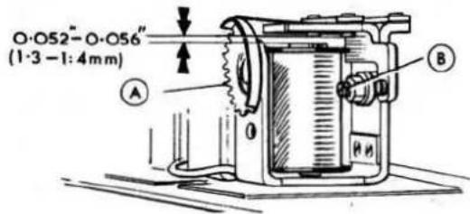
FIG.10.21. RB.340 CONTROL BOX. VOLTAGE REGULATOR GAP SETTING
A Tum cam fully anti-clockwise B Slacken contact screw

Fig.10.23. SF.6 Fuse unit
20 Fuses - general
Two live glass cartridge type fuses of 35 and 50 amp capacity, and two spare fuses are carried in a Model SF6 fuse unit as illustrated in Fig 10.23.
The 35 amp fuse (B-A2) is in circuit with the interior lights, cigar lighter and headlamp flasher.
The 50 amp fuse (A3-A4) protects the circuits of the heater fan, direction indicators, braking lights, petrol gauge, overdrive solenoid, reversing light, windscreen wipers, overdrive or automatic transmission warning light, oil pressure gauge, water temperature, windscreen washer and the horns.
If either of the fuses blow due to a short circuit or similar trouble, trace and rectify the cause before fitting a new fuse. Do NOT fit a fuse of a higher capacity than that intended for the circuit it protects.

Fig.10.20. RB.340 control box. Checking the cut-in voltage

FIG.10.22, RB.340 CONTROL BOX CUT-OUT AIR GAP SETTING
1 Hinge spring
2 Armature
3 Bi-metal backing spring
4 Armature to bobbin core gap
5 Armature back stop
6 Fixed contact bracket
7 'B-B' terminal plate
8 Moving contact blade

natural_image
Diagram of an electrical control panel with multiple switches and a cable, no visible text or symbolsFig.10.24. Location of flasher unit
21 Flasher unit - general
The flasher unit is housed in a small cylindrical container and is mounted, as shown in Fig.10.24, underneath the wooden screen rail capping below the windscreen. The capping is removed by undoing the nut hidden away underneath at each end and then lifting off the assembly (see Chapter 12).
Inside the flasher unit is a switch which is operated automatically by the alternate heating and cooling of a wire. There is also a small relay to flash the switch warning light and failure of this light to flash will indicate a fault in the system.
22 Flasher unit - fault tracing and rectification
1 Check the bulbs for broken filaments.
2 Refer to the wiring diagram at Fig.10.25 and check all circuit connections.
3 Remove the screen rail capping by undoing the nut which will be found underneath at each end and then lift off the capping.
4 Switch on the ignition and check with a voltmeter that terminal "B" on the flash unit is at 12 volts with respect to earth.
5 Connect terminals "B" and "L" of the flasher unit together and now operate the direction-indicator switch, if the unit operates it is defective and must be replaced.
6 If the foregoing tests prove satisfactory, it must be the switch which is at fault and this is best tested by substitution.

Fig.10.25. Flasher unit wiring diagram
23 Windscreen wiper mechanism - fault diagnosis and rectification
The windscreen wiper is a two speed, thermostatically protected, self parking, cable rack unit is controlled by a switch giving Park, Normal and High Speed operation. If the motor is overloaded, the resultant overheating of the windings will cause a thermostat to trip and isolate the motor from the supply. Adjustment to the self parking mechanism can be made by turning the knurled nut near the cable rack outlet (Fig.10.26). Turn only one or two serrations at a time and check. Poor operation of the wiper mechanism can be either electrical or mechanical in origin. Unless the cause of the fault is apparent proceed as follows to determine the cause of the failure.
1 Refer to Fig.10.27. Check the voltage between the supply terminal of the motor (green cable connection) and earth using a first grade moving coil voltmeter. The voltage, with the wiper working normally, should be 11.5 volts and if the supply is found to be low, check the battery, the switch (by substitution), the cabling and the connections.
2 If the voltage is correct, disconnect the cable rack at the wiper gearbox and measure the light running current with a first grade moving coil ammeter connected in the supply cable. The light running current must not exceed 3.4 amps at Normal speed and if this exceeded, fit a new motor.
3 If the electrical tests prove satisfactory check the cable rack and tubing. The maximum permissible force to move the cable rack in the tube is 16 lbs with the wiper arms, blades and motor disconnected. You can take this measurement by hooking a spring balance in the hole in the cross-head and withdrawing the rack with the balance.
4 Binding of the rack can be due to kinked or flattened tubing or, if just replaced, due to faulty installation. Badly kinked or flattened tubing must be replaced and any bends of less than 9" radius reformed.
5 Check the wheel boxes for misalignment or looseness and rectify as necessary.

Fig.10.26. Type DR3 windscreen wiper motor (cover plate removed)
24 Windscreen wiper mechanism - removal and refitting of wiper motor and cable
1 Disconnect the battery.
2 Withdraw the wiper arms from the spindles by pressing down on the catch and pulling outwards.
3 Unscrew the large nut connecting the cable guide to the wiper motor.
4 Remove the setscrew securing the earth wire to the motor.
5 Note the position of the cable connections and then disconnect the cables at the motor.
6 Turn the road wheels to full left lock to give better access to the three nuts in the right wing valance which secure the motor to the body. Remove the nuts.
7 The wiper motor and cable can now be removed as an assembly by drawing the cable through the guide tube.
8 Refitting is the reverse of the removal procedure.
25 Windscreen wiper mechanism - removal and refitting of wheelbox
1 An exploded view of a wheel box is given in Fig.10.28. The wheelboxes (one per wiper) are located behind the right and left hand facia panels.
2 Disconnect the battery.
3 Unscrew the two nuts and then lift the screen rail capping off the brackets. Take care not to scratch the windscreen.
4 To remove the right hand panel, remove the dash casing from beneath the steering column by withdrawing the four screws and the two bezels of the flexible odometer and clock setting drives.
5 Detach the angle tie plate from the bottom hidden face of the facia board by removing the two nuts.
6 Take out the ignition key and the cigar lighter. Undo the two thumbscrews and fold the instrument panel downwards.
7 On cars with automatic transmission, remove the short control rod from the ball pin on the lever at the right hand side of the steering column.
8 Separate the upper and lower switch covers from the steering column.
9 Identify the snap connectors of the trafficator warning light harness, separate them and withdraw the harness.
10 Detach the steering column assembly from the body bracket by removing the two nuts and allow the rim of the steering wheel to lie on the driver's seat cushion.
11 Detach the side facia panel by removing the securing screws and nuts.
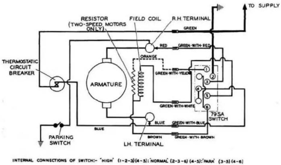
Fig.10.27. Wiring connections - switch to wiper motor

natural_image
Exploded view diagram of a mechanical assembly showing exploded view of components like gears, shafts, and bolts (no text or labels)Fig.10.28. A wheelbox
12 Detach the speedometer drive, all warning lights and leads from the instruments and detach the flexible control cable from the carburettor mixture lever quadrant by slackening the trunnion screw.
13 The right hand side facia panel can now be lifted out.
14 To remove the left hand facia panel, remove the four screws holding the dash casing beneath the glove box.
15 Remove the two screws and serrated washers securing the glove box panel to the instrument panel.
16 Remove the detachable side panel of the glovebox adjacent to the light switch. The panel is retained in position by adhesive.
17 Remove the two nuts and washers at the rear of the glovebox which secure the steady bracket to the body.
18 Remove the two nuts securing the wooden strip along the front of the tray.
19 Disconnect the two cables from the glovebox illumination light at their snap connectors.
20 Withdraw the left hand facia panel.
21 Withdraw both wiper arms from the spindles.
22 From outside the car, remove the large nuts securing the wheelboxes to the scuttle and take off the chrome distance pieces and the rubber seals.
23 Remove the backplates from the wheelboxes by undoing the two screws.
24 Pull away the cable from the worm wheels and slide off the
conduit tubing.
25 Withdraw the wheelboxes and conduits.
26 Refitting is the reverse of the above procedure but make sure that the flared end of the first wheelbox registers with the outer narrow slot in the cover plate.
26 Lighting equipment - removal, adjustment and refitting of components
1 To guard against accidental blowing of a fuse, it is always a wise precaution to disconnect the battery before breaking any connections which may leave you with bare cable ends.
2 Refitting of components is the reverse of the removal sequences given below.
3 To remove non-sealed beam headlamps,(Fig.10.29) take out the rim securing screw which will be found at the bottom of the rim and then pull out on the rim at the bottom to release it from the lipped catch at the top.
4 Press the light unit inwards against the three spring loaded adjustment screws and turn it anti-clockwise to disengage the unit from the keyhole slots.
5 Press in on the bayonet adaptor at the rear of the unit and turn anti-clockwise to remove the bulb. Note that a notch in the flange of the bulb is arranged to locate with a ridge in the bulb
holder. The light unit can now be removed.
6 Disconnect the bulb holder from the adaptor.
7 The sealed beam headlamps(Fig.10.30) are removed by first taking off the rim as described above and then removing the three cross headed screws to take off the headlamp retaining rim.
8 Withdraw the headlamp and unplug the adaptor at the rear of the unit.
9 Sealed beam headlamps are interchangeable with the non-sealed beam type provided they are fitted in pairs.
10 The headlamps should be set so that when the car is carrying its normal load, the driving beams are parallel with each other and with the road. However, although the headlamps can be set approximately at home, this is a job which, to get the best results, should be left to a garage having the necessary equipment for accurate alignment.
11 Vertical trimming of both types of headlamps is effected by adjustment of the top spring loaded screw whilst the two side screws are used for horizontal trimming. None of these screws should be touched when the headlamp is removed or alignment will be upset.
12 To remove the sidelamp (Fig 10.31), take out the screw in the top of the lamp nacelle, turn the rim clockwise and then pull forward to withdraw the lamp and bulb holder, you may find it necessary to ease the cable through the grommet under the wing in order to get enough movement on the unit to clear the nacelle. Press inwards on the bulb and turn anti-clockwise to remove it. Press the cables out of the connectors at the rear of the unit and remove it from the car.
13 The front flasher unit assembly (Fig.10.32) is held to the front wing by three screws and to get at these the rim of the unit
must first be removed by taking out the screw at the bottom and then lifting off the rim and glass. The bulb can now be taken out. Now remove the holding screws and remove the unit from the car. Slide back the body rubber and disconnect the cables.
14 To remove the Stop/Tail/Flasher lamp, Figs.10.33 and 10.34, first take out the screw at the bottom of the lamp glass, lift the glass outwards and upwards from the bottom to release it. The bulbs can now be taken out.
15 A screw will be seen just above the reflector unit, remove it and then take out the screws securing the hardboard trim in the luggage compartment and remove the trim. Remove the plinth securing nut and the plinth and rubber seating gasket can now be removed, Disconnect the cables.
16 The light unit of the fog lamp (Figs.10.35 and 10.36) is removed by taking out the screw at the bottom of the lamp, now disengage the rim at the top and withdraw the light unit from the back shell. Ease back the earth contact and withdraw the bulb.
17 When replacing the bulb, align the groove in the bulb plate with its register in the reflector.
18 When refitting the later type fog lamp unit, be careful to ensure that the contact blade coupled to the red/yellow cable registers with the centre contact on the bulb.
19 The beam of the fog lamp is adjusted by slackening the nut of the attachment bolt, which on the later type is accessible from beneath the car, and then moving the lamp to the desired position. But, as with the headlamps, to get the full benefit from the lights it is best to have the lamps correctly aligned at a garage with the necessary equipment for the work.

Fig.10.29. Headlamp removal (non-sealed beam)

natural_image
Technical line drawing of mechanical components with no visible text or symbolsFig.10.30. Removal of sealed beam units

natural_image
Line drawing of a curved mechanical or biological structure with two protruding components (no text or symbols)Fig.10.31. Removing a sidelamp

natural_image
Technical line drawings of mechanical components including a screw, a bulb, and a curved housing (no text or symbols)Fig.10.32. The front flasher unit

Fig.10.33. Rear/Stop/Flasher lamp unit (early models)

natural_image
Line drawing of two electronic devices with labeled parts, one emitting a light bulb (no text or symbols present)Fig.10.34. Rear/Stop/Flasher lamp unit (later models)

Fig.10.35. Fog lamp (early type)

natural_image
Technical line drawing of two open circular mechanical components with internal components and a light bulb at the base (no text or symbols)Fig.10.36. Fog lamp (later type)

Fig.10.37. Type 5SJ windscreen washer unit
27 Windscreen washer (electrical) - testing in position
Early cars were fitted with a windscreen washer operating by vacuum but later models are equipped with an electrically operated Lucas 5SJ unit as illustrated in Fig.10.37. In the event of faults arising in this equipment proceed as follows.
1 Check the polarity as indicated on the moulding housing and then connect a direct current voltmeter to the motor terminals.
2 Switch on the ignition and then operate the washer switch at the same time observing the voltmeter. If a low or zero voltage is indicated, check the fuse, the switch and external connections and rectify as necessary.
3 If the voltmeter gives a reverse reading, transpose the connections to the motor.
4 If supply voltage is indicated at the terminals but the unit fails to operate, an open circuit winding or a fault in the brush gear can be suspected and the motor should be dismantled and tested as outlined in Section 28.
5 If the motor can be heard to operate but does not move freely, connect a suitable DC ammeter in series with the motor and operate the switch. If the current reading exceeds 2 amps, remove the motor and check that the pump impeller shaft rotates freely. If the shaft is difficult to turn, the water pump unit will have to be replaced. If the shaft turns freely, the fault is in the motor which will have to be dismantled for inspection.
28 Windscreen washer (electrical) - dismantling, testing and reassembling
1 Disconnect the external tube and the electrical connections and remove the cover from the bottle.
2 Remove the self tapping screw securing the motor to the cover and lift off the motor unit but be careful not to lose the coupling which connects the armature coupling to the pump spindle coupling. In some models it will be found that this coupling is a piece of split tube and cases have been experienced where this slips, and although the motor operates, the pump spindle is not turned. If this occurs, squeeze the tube with a pair of pliers to tighten it on the pump and armature spindles.
3 Remove the armature coupling from the armature shaft by holding the shaft with a pair of pointed pliers and, using a second pair of pliers, draw off the armature coupling.
4 Remove the screws from the bearing plate and take off the plate and the rubber gasket.
5 Take out the two screws holding the terminals and the terminal nuts and brushes can now be removed and the armature withdrawn, but take care not to lose the bearing washer which is loosely fitted to the armature shaft.
6 It is advised that you do not disturb the pole assembly unless this is absolutely necessary. If it has to be removed, take careful note of its position in relation to the motor housing. The narrower pole piece is adjacent to the terminal locations. Also take note of the position of the pole clamping member which, when fitted correctly, locates on both poles, if it is not fitted correctly pressure will be applied to one pole piece only.
7 If the motor has been overheated or if any part of the housing is damaged, there is no alternative to replacement.
8 Examine the armature, if it is damaged or if the windings are loose or badly discoloured, fit a new armature.
9 Clean the commutator with a non-fluffy cloth moistened in petrol and if it is badly discoloured, polish it with very fine glass paper.
10 Check the resistance of the armature winding using an ohmmeter. The resistance should be 2.8 - 3.1 ohms.
11 Examine the brushes, if they are less than 1/16" (1.59 mm) in length they should be replaced.
12 Reassembly of the unit is the reverse of the dismantling procedure but watch the following points:-
a) Fill the bearing recess in the motor with Rocal Molypad molybdenised grease and be sure to remove any excess from the face of the bearing boss.
b) See that the pole piece assemblies are secure and that they are firmly located on the circular spigot and are the right way round.
c) Make sure that the brushes bear firmly against the commutator.
d) Before replacing the motor on the cover, be sure that the armature coupling is pushed fully home and that the intermediate coupling is in place.
29 Heater fan motor and fan switch - testing, removal and refitting
1 In the event of malfunctioning of the heater fan motor, first check that current is reaching the motor by connecting a voltmeter to the input terminal and to earth. Switch on the ignition and the heater fan switch and observe the reading on the voltmeter. If there is no reading check through the connections and test the switch by substitution.
2 If current is reaching the motor and all connections are clean and in good order, the motor will have to be replaced with a new item.
3 The heater unit must be removed in order to take off the motor and full instructions for this work will be found in Chapter 12.
4 Having removed the heater unit, unscrew the nut holding the fan on the motor spindle and withdraw the fan.
5 Remove the three setscrews and plain washers holding the fan
motor to the case assembly and then take off the rubber washers which will be found under the plain washers.
6 Lift off the motor and collect the three rubber washers which were over the setscrews and between the motor flange and the case assembly. Remove the earth wire fitted under one of the securing setscrews and then take off the felt washer from the motor spindle.
7 Refitment of the motor is the reverse of the removal sequence.
8 If the fault lies in the switch, first disconnect the battery.
9 Remove the two thumb screws which secure the instrument panel and fold the panel downwards after removing the digar lighter and the ignition key.
10 Note the location of the cable connections to the three Lucar tags at the back of the switch and then pull off the cables.
11 Unscrew the chrome bezel which holds the switch to the instrument panel taking care, of course, not to scratch the panel.
12 Remove the switch from the rear of the panel.
13 Refitting the fan switch is the reverse of the above removal procedure.
30 Horns and horn relay - fault tracing and rectification
Mk 1 and early Mk 2 cars are fitted with one high and one low note model HF 1748 horns, later Mk 2 cars have model WT 618 U and the latest are equipped with model 9H. The horns are mounted at the front end of the car on either side of the engine compartment immediately below the radiator. The model 9H horn circuit operates through a Lucas 6RA relay which is mounted on the left hand wing valance adjacent to the fuse block. Model HF 1748 and WT 618 U horns can be adjusted whilst installed on the car but model 9H horns will have to be removed for adjustment.
1 In the event of a horn failing to sound or its performance becoming unsatisfactory, make sure that the fault is not due to external causes before making any adjustments. The most common faults likely to be experienced are :-
a) Battery condition
b) Loose or broken connections in the horn circuit. This can be checked by using a voltmeter or test lamp.
c) Loose fixing bolts on horn mounting bracket.
d) Faulty relay. First check that current is available at the terminal carrying the brown/blue cable and atthe terminal to which the green cable is connected.
e) Make sure that the fuses have not blown.
f) We have has experience of the horn slip ring on the inner steering column (see Chapter 11) being worn through due to a broken spring contact. This was an extreme case but is quoted as an illustration of thenecessity for thorough checking before suspecting faults in the horn itself.
2 A Model HF 1748 horn in correct adjustment will pass 3.5 to 4 amps. Adjustment must be effected with the ignition switched "ON" and the horn push (ring) depressed and using a 0-10 amp moving coil ammeter. Turn the horn adjustment screw (Fig.10.38) clockwise to increase the current and anti-clockwise to decrease it. Adjustment does not alter the note of the horn but takes up wear in the moving parts which, if not corrected, will result in loss of power and roughness in tone.
3 To adjust the Model WT 618 U horn (Fig.10.39) first remove the domed cover by taking out the centre screw. Connect a 0-20 amp first grade ammeter in series with the horn and then slacken the locknut to the contact. Now switch on the ignition and operate the horn push (ring) and adjust the contact to give 13.5 to 15.5 amps at 12 volts. Retighten the locknut and refit the dome.
4 The Model 9H horn must be removed from the car for adjustment. A small serrated adjustment screw, "A" in Fig.10.40, is provided to take up wear only, alteration of its position will not affect the pitch of the note. The screw "B", the centre slotted core must on no account be disturbed.
5 Connect a 0-25 moving coil ammeter in series with the horn supply feed and protect the ammeter from overload by connecting an ON-OFF switch in parallel with its terminals, keep the
switch "ON" whilst taking readings.
6 Turn the adjustment screw "A" anti-clockwise until the horn just fails to sound and then slowly turn it clockwise until the horn operates within the limits of 6.5 - 7.0 amperes.
7 Model 9H horns can be fitted as replacements for the other types provided that the cable connections are changed for Lucar tags. When fitting replacement horns, make sure that the lock-washers are correctly positioned one each side of the mounting bracket and ensure that the 5/16" centre fixing bolt is secure but not overtight; overtightening of this bolt will damage the horn. If you use a centre fixing bolt or other than the correct type, the bolt must nonot be screwed into the horn to a depth greater than 11/16" (17.5 mm).
8 If the horn relay is not heard to operate when the horn push or ring is operated with the ignition switched "ON" it can be suspected of being faulty but first make sure that the fuses have not blown.
9 Check with a test lamp that current is present, with the ignition switched "ON", at the terminal carrying the green cable. Check also that the terminal carrying the brown/purple cable is live.
10 Remove the purple/black cable and earth the terminal to a clean part of the frame. The relay coil should now operate and the contacts should be heard to close. Reconnect the cable.
11 Failure of the above tests means that the relay is faulty and must be replaced.
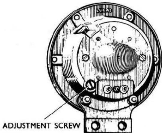
Fig.10.38. Model HF.1748 horn

Fig.10.39. Model WT.618.U horn (domed cover removed)

Fig.10.40. Model 9H horn
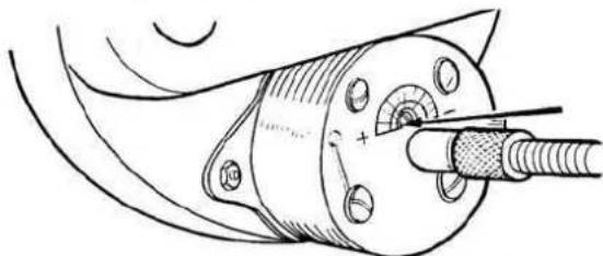
natural_image
Technical line drawing of a mechanical component with threaded end and internal features (no text or symbols)Fig.10.41. Clock adjusting screw
31 Electric clock - removal and adjustment
1 Both the speedometer and the revolution counter must first be removed and instructions for this are given in Sections 36 and 37.
2 Detach the clock from the hidden face of the revolution counter by taking off the two nuts. Take the flexible setting drive off the clock by undoing the knurled sleeve.
3 If the clock needs adjustment refer to Fig.10.41 and turn the small screw towards the minus sign if the clock is gaining and towards the plus sign if losing. The action of setting the hands automatically starts the clock.
32 Miscellaneous interior equipment and indicator lights replacement of bulbs
1 The brake fluid and handbrake warning light bulb is replaced by unscrewing the bezel of the lamp taking care to control the run of the spring loaded bulb. Take out the bulb and feed the replacement into the spring loaded bulb holder, make sure that the red transparent window is retained in the bezel by a small circlip, position the designation plate on the bulb holder and then screw on the bezel. The bulb holder itself can be removed after taking out the bulb and removing the side facia panel.
2 To replace the carburettor mixture control warning light (if fitted), take out the four screws followed by the two bezels of the odometer and clock setting drives and remove the dash casing beneath the steering column. Pull off the bulb holder from the rear of the light unit above the lever quadrant. Replace the bulb and the other components in the reverse sequence to the foregoing. The lamp unit itself can be removed after removal of the bulb by unscrewing the body of the unit and withdrawing the red transparent window from the front face of the facia board.
3 To adjust the carburettor mixture control warning light switch, remove the dash casing from underneath the steering column as described above. Set the mixture control lever 14 " (6.350 mm) from the bottom limit of its travel, adjust on the nuts on the threaded shank of the switch until the light goes out
when the ignition is switched "ON". Tighten the nuts and actuate the lever a few times to make any final adjustment as may be necessary. Refit items in the reverse order to that in which they were removed.
4 The overdrive and intermediate speed hold switches are removed by first taking off the dash casing beneath the steering column in the manner described in paragraph 2. Disconnect the battery. Remove the switches from the hidden face of the instrument facia by rotating the screwed ring anti-clockwise. Collect the escutcheon plate. Refit the switches in the reverse order.
5 The flashing indicator control is removed by first disconnecting the battery as a precautionary measure. Remove the screws and take off the upper and lower switch covers from around the steering column. Take off the dash casing from underneath the steering column as described in paragraph 2. Disconnect the seven cable harness at the snap connectors on the left hand side of the steering column after making sure that you are conversant with the location of cables for refitment. Take out the two horizontally positioned screws at the right hand side of the control lever and then lift off the lever. Refitting is the reverse of the foregoing.
6 To replace the flashing indicator warning light bulbs, remove the screws securing the upper cover around the steering column. Withdraw one, or both, bulb holders from the sockets in the upper cover and remove the bulb from the holder by pressing inwards and rotating 90° in either direction. The bulb is replaced by inserting the cap into the bulb holder and then rotating it 90° until the notches inside the bulb holder are located. Replace all items in the reverse order to the foregoing.
7 The map light bulb which is located in the centre forward part of the screen capping, is removed by pressing inwards and then rotating in either direction until the bayonet cap becomes free and is replaced in the reverse manner. If the map lamp unit is to be removed it will be necessary to take off the screen capping by undoing the two hidden nuts at each end (see Chapter 12) and then lifting it off the brackets, watch that you do not mark the windscreen. The lamp unit is attached to the capping by two screws, identify the leads to the unit and then take out the two screws and remove it. The lamp unit is refitted in the reverse order to that in which it was removed.
33 Revolution counter AC generator, if fitted - testing
1 In the event of malfunctioning of the revolution counter, first check the leads and connections from the generator, which is located at the rear of the right hand camshaft, to the hidden face of the instrument in the car.
2 If the leads and connections appear to be satisfactory, detach the leads from the terminals at the generator and then connect an AC voltmeter across the terminals.
3 Start the engine and observe the voltmeter, as a rough guide the output of the generator is about one volt per 100 rpm. If the output is satisfactory, it is the instrument which is at fault and this will have to be removed and replaced as described in Section 37.
4 If there is no output from the generator or if the output is low or fluctuating, the generator will have to be replaced. Instructions for the removal and refitment of the AC generator are given in Chapter 1.
34 The instrument panel - removal and refitting
1 Disconnect the battery.
2 Paragraphs 3-15 (inclusive) cover the work for Mk 1 models.
3 For Mk 1 cars, first remove the dash casing by removing the scuttle vent lever knob and then taking out all the screws from the casing which can now be drawn downwards.
4 Refer to Fig.10.42 and take off the facia panel by removing the thumb screws (A) and the cigar lighter (B). Now depress the plunger in the side of the light switch (C) and withdraw the lever
and repeat this for the wiper switch knob (D). Take out the ashtray (E) and working from underneath, remove the two screws (H). The panel can now be removed by sliding it over the remaining switches.
5 Partially drain the radiator and then unscrew the water temperature gauge bulb from the inlet manifold water jacket by holding the flats on the bulb and unscrewing the union nut.
6 Remove the grommet at the rear of the engine compartment through which the oil gauge pipe and the water temperature capillary tube pass.
7 Release the capillary tube from its clips taking care not to bend the tube.
8 Now refer to Fig.10.43 which shows the instrument panel with the centre facia removed.
9 Remove the two screws which secure the clock adjuster cable on the cowl adjacent to the left hand heater door.
10 Mark the position of the three instrument panel securing bolts and then remove them.
11 Ease the panel forward taking care not to strain the water temperature gauge capillary tube, and then unscrew the flexible cable unions to the revolution counter and the speedometer.
12 Working from above, unscrew the pipe connection to the oil pressure gauge.
13 Identify the electric leads to the various services and disconnect them.
14 Ease the panel forward into the car at the same time having an assistant to watch that the capillary tube does not foul any projection and is not kinked whilst being withdrawn through the bulkhead.
15 Having removed the panel it is advisable to immediately remove the water temperature/oil pressure gauge to prevent damage to the capillary tube. The gauge is removed by undoing the two securing screws and withdrawing the gauge forward out of the panel.
16 The following paragraphs cover the removal of the instrument panel from the Mk 2 and later model cars.
17 Remove the ignition key and the cigar lighter.
18 Undo the thumb screws at the top of the panel and then hinge the panel downwards (Fig.10.44).
19 Examine the electrical connections closely and, after identification, disconnect them from the various services.
20 Remove the electrical harness and clips from the panel posts by withdrawing one screw from each and now remove the harness clip and screw from each hinge inside the panel aperture.
21 Working from beneath the panel and above the "newspaper" tray, take out the two bolts from the extended portion of each hinge.
22 The panel can now be lifted out.
23 Refitting is the reverse of the above removal sequences but extreme care must be taken when installing the panel on Mk 1 models to ensure that the capillary tube is not damaged in any way; to this end we suggest that the water temperature/oil pressure gauge is refitted to the panel after the panel has been installed. In each case be sure, by reference to the wiring diagram, that electric leads are refitted in accordance with the colour coding.
35 The instrument panel components - removal and refitting
The following work can be done without removing the instrument panel from the car but first disconnect the battery and then, for Mk 1 cars, remove the centre facia and the panel securing bolts in the manner described in paragraphs 3 - 11 of Section 34 so that the panel can be eased forward. For Mk 2 and later models, remove the ignition key and take out the cigar lighter and then remove the two thumb screws at the top of the instrument panel and hinge the panel downwards.
Refitment of each item is generally the reverse of the order in which it was removed but be certain, by reference to the appropriate wiring diagram, that leads are replaced correctly according to their colour coding.
1 The ignition switch on Mk 1 cars is removed by undoing the locking ring securing it to the panel and then pushing the switch

Fig.10.42. Removal of the centre facia panel (Mk.1 models)

Fig.10.43. Instrument panel Mk.1 models (centre facia panel removed)

natural_image
Technical line drawing of an electrical enclosure with visible wiring and components (no text or labels)Fig.10.44. Instrument panel, later type, hinged down
out to the rear of the panel. The leads can now be identified and then disconnected.
2 The ignition switch of Mk 2 models is removed by first identifying and then removing the leads. Now unscrew the chrome ring and take out the switch by inserting a piece of wire through the hole in its body.
3 Faults in the cigar lighter will most probably be due to failure of the element and to change this, hold the unit in the palm of the hand, knob first, and pull the sleeve down against the pressure of the spring. Unscrew the lighter element and fit the replacement. The lighter unit is removed from the panel by detaching the leads and taking off the nut and "U" piece from the centre terminal post after which the unit can be withdrawn from the front face of the panel. When refitting, make sure that the terminal post is firm and tight and that the insulating washer in the "U" piece is also tight and is in good condition. A poorly fitting washer or a washer in poor condition can cause a direct short.
4 To remove the starter push switch from Mk 1 models, take off the nut at the front of the panel, push the switch out through the back of the panel and take off the leads. For Mk 2 and later model cars, first remove the leads from the switch, remove the nut from the hidden face and withdraw the switch from the front of the panel.
5 The head, side and fog light switch is removed by first depressing the small plunger at the right hand side of the switch operating lever and then pulling the lever off the spindle, this work has already been done in the case of Mk 1 cars when the centre facia panel was removed. Now, for Mk 1 cars, remove the nut at the front of the panel and push the switch to the rear, disconnect the leads and remove the switch. For Mk 2 cars, disconnect the leads, remove the nuts from the posts holding the switch and withdraw the switch from the front of the panel. The designation plate is attached to the centre facia panel on Mk 1 cars but for Mk 2 models it is attached to the instrument panel by a nut. When refitting the control lever in each case make sure that it is pressed far enough on to the spindle for the plunger to engage the drilling in the side of the lever, a smear of vaseline on the spindle may help.
6 The tumbler type switches of Mk 2 cars are removed by first detaching the leads and then, holding the switch lever in the horizontal position, unscrew the chrome ring at the front of the panel and withdraw the switch. The switches on Mk 1 cars are removed by undoing the nut or locking ring securing the switch to the panel and then push the switch out to the rear of the panel and detach the leads.
7 The ammeter and fuel gauges fitted to Mk 1 cars are removed by undoing the two securing screws and then pulling the gauge forward into the car so that the leads can be detached. These gauges fitted to Mk 2 cars are attached to the panel by means of knurled finger nuts passing through a "U" piece. Detach the leads from the back of the gauges, undo the finger nuts and press the gauge out from the back of the panel. When refitting the gauges to Mk 2 models, make sure that the "U" piece does not foul any terminal or bulb holder.
8 To remove the oil pressure and water temperature gauges from Mk 2 cars, in which they are separate items, proceed in the manner described in paragraph 7 for the ammeter and fuel gauge. The oil pressure and water temperature indication is given by a combined gauge in Mk 1 cars and to remove it first partially drain the radiator and then remove the temperature gauge bulb from the inlet manifold water jacket by holding the flats on the bulb and unscrewing the union nut. Now remove the grommet on the bulkhead at the rear of the engine compartment through which the water temperature capillary tube and the oil gauge pipe pass. Remove the capillary tube from the various securing clips taking care not to bend it. Unscrew the union nut holding the oil pressure pipe to the rear of the gauge. Remove the two screws securing the gauge to the panel and now withdraw the gauge from the front of the panel taking care not to bend the capillary tube and at the same time have an assistant to watch that the tube does not become caught up and to help guide it through the bulkhead.
9 The voltage regulator for the fuel and water temperature gauges, fitted to Mk 2 and later model cars only, is situated at the top right hand side of the panel and is removed by detaching the leads and by taking off the one securing nut. Make certain that a good earth is made between the regula tor and the panel when you are refitting it.
10 The instrument illumination bulbs are housed in holders at the back of each instrument. Pull off the holder and then remove the bulb by turning it anti-clockwise.
11 Removal of the speedometer and the revolution counter from the instrument panel of Mk 1 cars is covered in Sections 36 and 37.
36 Speedometer and speedometer drive cable - removal and refitting
1 Disconnect the battery. 2 The following paragraphs 3-9 (inclusive) cover the removal of the instrument from Mk 1 cars.
3 Remove the dash casing, the centre facia panel and the instrument panel, to the extent of being able to pull it forward for access, in the manner described in Section 34 paragraphs 3 11 inclusive.
4 Unscrew the pipe connection from the rear of the oil pressure gauge.
5 Unscrew the union nut attaching the flexible drive to the rear of the instrument.
6 Withdraw the two warning light bulb holders from the rear of the instrument.
7 Remove the three screws securing the speedometer to the panel and remove the instrument from the front of the panel.
8 Unscrew the speedometer cable drive connection at the gearbox or overdrive, as applicable, and detach the cable from the retaining clips.
9 Remove the grommet from the bulkhead at the rear of the engine compartment through which the cable passes and then withdraw the cable.
10 The following paragraphs refer to removal of the speedometer from Mk 2 and later model cars.
11 Remove the dash casing from beneath the side facia panel by taking out the four screws and the two bezels from the odometer and clock setting drives.
12 Working from underneath, remove the knurled sleeve securing the flexible drive to the instrument.
13 Detach the electrical leads from the back of the speedometer after identifying their location for correct refitment.
14 Remove the two knurled securing nuts and then withdraw the instrument from the front of the facia board.
15 Remove the flexible drive cable in the manner described in paragraphs 8 and 9 above.
16 The inner flex of the drive cable can be removed, after removing the instrument, with the outer casing in situ. However, if the inner flex is broken, it will be necessary to disconnect the outer casing at the gearbox and to then withdraw the inner flex from both ends.
17 Refitting of the speedometer is the reverse of the removal operations in both cases but as the correct performance of the instrument depends to a very great extent on the serviceability of the drive cable and its connections, particular attention should be paid to the following points:—
a) The run of the flexible drive must be smooth with a minimum bend radius of 6" and with no bend within 2" of any securing point. Change the position of clips to meet that requirement if it is necessary.
b) Clip the drive at suitable points, do not allow it to flap freely. c) Avoid crushing the outer casing by overtightening on a clip. d) The outer flex connections should be finger tight only.
e) The flexible drive should be lubricated periodically (10,000 miles servicing).
f) The inner flex must protrude 3/8" beyond the outer case as shown in Fig.10.45.
Note Speedometer needle waver, a common fault, can be caused
by lack of lubrication of the inner cable, kinked cable, crushed outer case, connections overtightened, severe bends in the cable, insufficient engagement of the inner cable (Fig.10.45) etc.

Fig.10.45. Engagement of inner flex of speedometer drive cable
37 The revolution counter - removal and refitting
1 Disconnect the battery.
2 The following paragraphs 3-8 (inclusive) cover the removal of the instrument from Mk 1 cars.
3 Remove the dash casing, the centre facia panel and the instrument panel, to the extent of being able to pull it forward for access, in the manner described in Section 34 paragraphs 3-11 inclusive.
4 Unscrew the pipe connection from the rear of the oil pressure gauge.
5 Unscrew the flexible cable (if fitted) from the rear of the instrument.
6 Disconnect the cables from the electric clock and, if applicable, from the instrument.
7 Remove the three screws securing the revolution counter to the panel and withdraw it from the front of the panel.
8 Disconnect the flexible drive (if fitted) by undoing the union at the camshaft drive, remove the grommet from the engine bulkhead and withdraw the drive.
9 The following paragraphs refer to the removal of the revolution counter from Mk 2 and later cars.
10 To improve access, remove the speedometer as described in the previous Section.
11 Remove the illumination lamps from the back face of the instrument and from the clock.
12 Detach the two centre leads and the earth lead.
13 Take off the two knurled nuts and then withdraw the instrument from the front of the facia.
14 Remove the clock as described in Section 31.
15 Refitting in both cases is the reverse of the removal procedure but the attention of owners, of those cars fitted with a flexible drive to the counter, is drawn to paragraph 17 of Section 36.
38 The bi-metal resistance instrumentation - fault finding
The engine temperature, engine oil pressure and petrol tank contents gauges fitted to later model cars are operated by transmitters mounted on the engine or in the fuel tank. The gauge units operate on the thermal principle having a heater winding wound on a bi-metal strip. The transmitter units of the engine temperature and petrol tank contents gauge are of the resistance type whilst the oil pressure transmitter is of the thermal pressure principle also with a heater winding wound on a bi-metal strip but having a contact at one end with a second contact mounted on a diaphragm sensitive to the pressure of the oil. Wiring diagrams for these systems are given in Figs.10.46, 10.47, 10.48 and 10.49.
The possible cause of faults, as indicated by gauge readings, is given in the following charts.
39 Wiring diagrams - colour coding
Wiring diagrams for the various models are given in Figs.10.50, 10.51, 10.52 and 10.53. The cable colour code used in these diagrams is given below.
Note: When a cable is shown as having two colour code letters, the first letter denotes the main colour and the second denotes the tracer colour.
| B | Black | P | Purple | Y | Yellow |
| U | Blue | G | Green | D | Dark |
| N | Brown | S | Slate | L | Light |
| R | Red | W | White | M | Medium |
| K | Pink |

Fig.10.46. Wiring diagram of the fuel tank contents and water temperature gauges with the voltage regulator
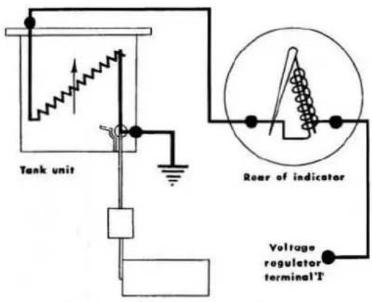
Fig.10.47. The fuel tank contents gauge circuit
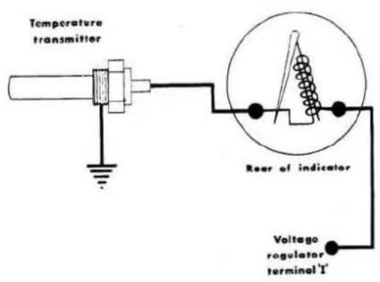

Fig.10.48. The water temperature gauge circuit

Fig.10.49. The engine oil pressure gauge circuit


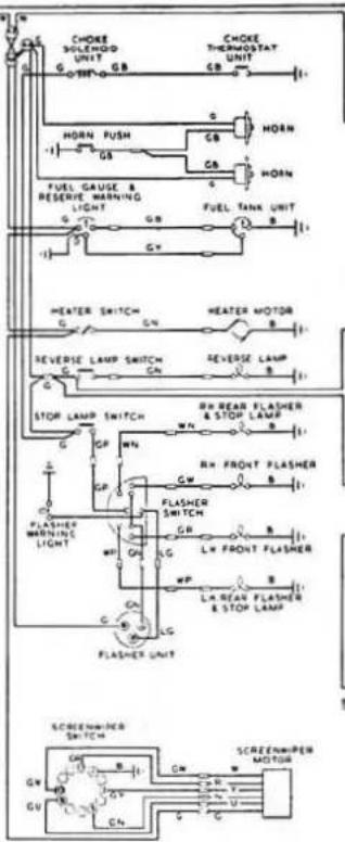

CABLE COLOUR CODE
| B | BLACK | P | PURPLE | Y | YELLOW |
| U | BLUE | G | GREEN | D | DARK |
| N | BROWN | S | SLATE | L | LIGHT |
| R | RED | W | WHITE | M | MEDIUM |
When a cable has two colour code letters, the first denotes the main colour and the second denotes the tracer colour.
Fig.10.50. Wiring diagram for 2.4 and 3.4 litre Mk.1 models
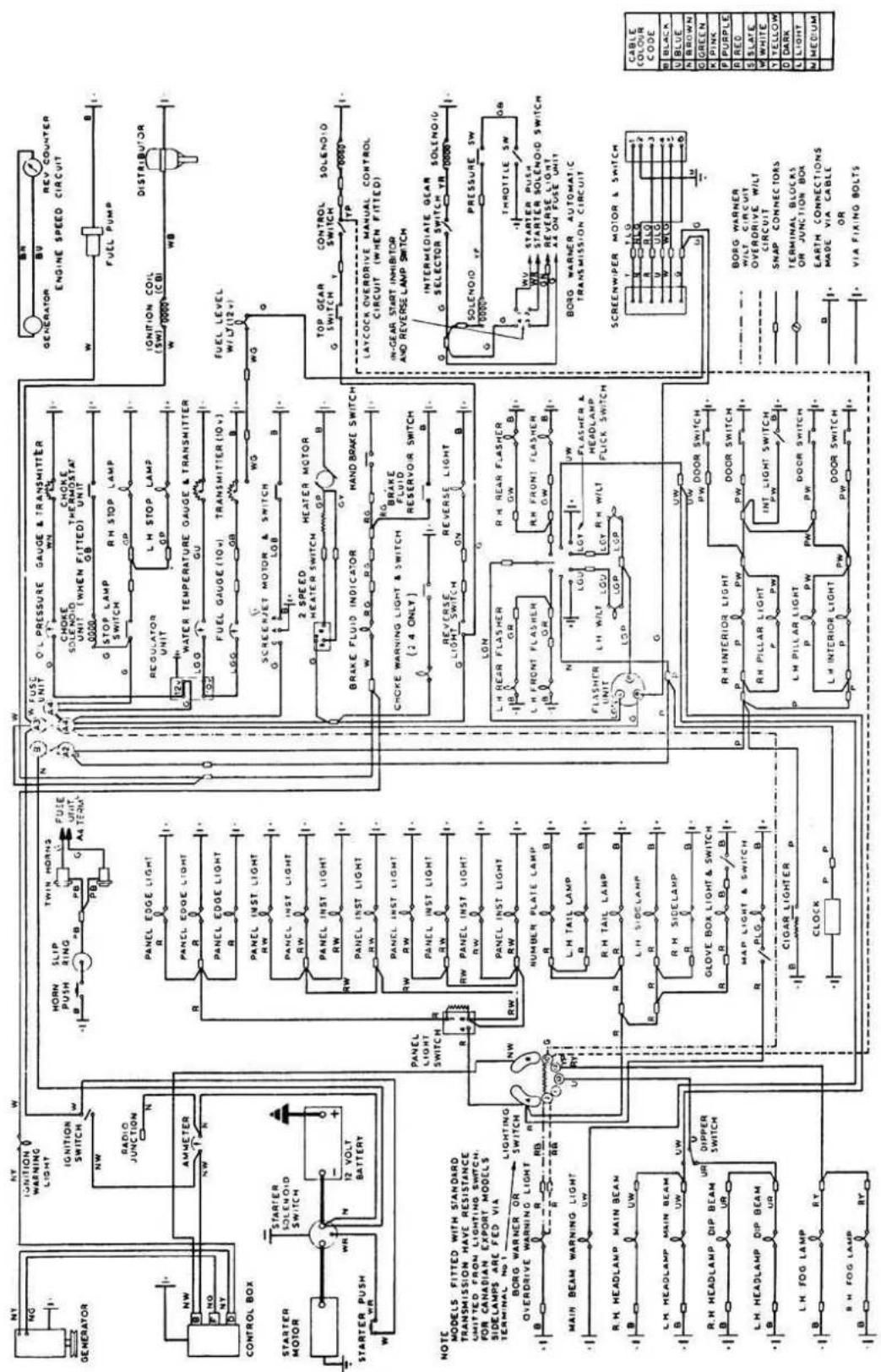
Fig.10.51. Wiring diagram for the 2.4, 3.4 and 3.8 litre Mk.2 right hand drive models

Fig.10.52. Wiring diagram for the 2.4, 3.4 and 3.8 litre Mk.2 left hand drive models

Fig.10.53. Wiring diagram for the 240 and 340 models

Fig.10.54. Layout of the wiring harness
FIG. 10.55. ANALYSIS OF ENGINE OIL PRESSURE GAUGE FAULTS
NOTE: THE INSTRUMENT PANEL GAUGE MUST NEVER BE CHECKED BY SHORT CIRCUITING THE TRANSMITTER UNIT TO EARTH
| Symptom | Unit Possibly at Fault | Action |
| Instrument panel gauge showing a “zero” reading | Wiring | Check for continuity between the gauge and the transmitter unit and that the latter is earthed. |
| Instrument panel gauge | Check for continuity between the gauge terminals with leads disconnected. If satisfactory replace the transmitter unit. | |
| Instrument panel gauge showing a reading with ignition switched but engine not running | Transmitter unit on oil filter head | Check by substituting another transmitter unit. |
| Instrument panel gauge showing a high reading and overheating | Transmitter unit on oil filter head | Check by substituting another transmitter unit. |
| Instrument panel gauge showing a below “zero” reading with ignition switched off | Instrument panel gauge | Check by substituting another instrument panel gauge. |
FIG. 10.56. ANALYSIS OF ENGINE TEMPERATURE AND PETROL TANK CONTENTS GAUGES FAULTS
NOTE: THE INSTRUMENT PANEL GAUGES MUST NEVER BE CHECKED BY SHORT CIRCUITING THE TRANSMITTER UNITS TO EARTH
| Symptom | Unit Possibly at Fault | Action |
| Instrument panel gauge showing a "zero" reading | Voltage regulator | Check output voltage at terminal 1 (eye) is 10 volts. |
| Instrument panel gauge | Check for continuity between the gauge terminals with the leads disconnected. | |
| Transmitter unit in petrol tank or engine unit | Check for continuity between the terminal and the case with lead disconnected. | |
| Wiring | Check for continuity between the gauge, the transmitter unit and the voltage regulator. Also that the transmitter unit and voltage regulator are earthed. | |
| Instrument panel gauge showing a high low reading when ignition is switched on | Voltage regulator | Check output voltage at terminal 1 (eye) is 10 volts. |
| Instrument panel gauge | Check by substituting another instrument panel gauge. | |
| Transmitter unit in petrol tank or engine unit | Check by substituting another transmitter unit in petrol tank or engine unit. | |
| Wiring | Check for leak to earth. | |
| Instrument panel gauge showing a high reading and overheating | Voltage regulator | Check output voltage at terminal 1 (eye) is 10 volts |
| Wiring | Check for short circuits on wiring to each transmitter unit. | |
| Instrument panel gauge showing an intermittent reading | Voltage regulator | Check by substituting another voltage regulator. |
| Instrument panel gauge | Check by substituting another instrument panel gauge. | |
| Transmitter unit in petrol tank or engine unit | Check by substituting another transmitter unit in petrol tank or engine unit. | |
| Wiring | Check terminals for security, earthing and wiring continuity. |

flowchart
graph TD
    A["FEED"] --> B["LINE FUSE"]
    B --> C["N"]
    C --> D["B"]
    D --> E["LGP"]
    E --> F["B"]
    F --> G["HAZARD PILOT LAMP"]
    G --> H["HAZARD SWITCH"]
    H --> I["IGNITION SWITCH"]
    I --> J["G"]
    J --> K["N"]
    K --> L["BLACK IDENT"]
    L --> M["A4"]
    L --> N["A3"]
    M --> O["W"]
    N --> P["W"]
    O --> Q["GR"]
    P --> R["GR"]
    Q --> S["GR"]
    R --> T["L.H. REAR FLASHER LAMP"]
    T --> U["GR"]
    U --> V["L.H. FRONT FLASHER LAMP"]
    V --> W["GR"]
    W --> X["L.GN"]
    X --> Y["P"]
    Y --> Z["LPG"]
    Z --> AA["CAR PILOT LAMP"]
    AA --> AB["DIRECTION INDICATOR SWITCH"]
    AB --> AC["GR"]
    AC --> AD["L.H. REAR FLASHER LAMP"]
    AD --> AE["R.H. FRONT FLASHER LAMP"]
    AE --> AF["G"]
    AF --> AG["R.H. FRONT FLASHER LAMP"]
Fig. 10.57. Wiring diagram for traffic hazard warning system
Chapter 11 Suspension, and steering
Contents
| General description | ... | ... | ... | ... | ... | 1 |
| Front suspension assembly - removal and refitting | ... | ... | ... | ... | ... | 2 |
| Hydraulic damper (front)- removal and refitting | ... | ... | ... | ... | ... | 3 |
| Coil springs - removal and refitting | ... | ... | ... | ... | ... | 4 |
| Front wheel hub - removal, dismantling and refitting | ... | ... | ... | ... | ... | 5 |
| Stub axle carrier and lower wishbone ball joint - removal, adjustment and refitting | ... | ... | ... | ... | ... | 6 |
| Lower wishbone - removal, replacement of bushes and refitting | ... | ... | ... | ... | ... | 7 |
| Upper wishbone and upper wishbone ball joint - removal, replacement of bushes and refitting | ... | ... | ... | ... | ... | 8 |
| Anti-roll bar - removal, refitting and replacement of rubber bushes | ... | ... | ... | ... | ... | 9 |
| Accidental damage to front suspension components.. | ... | ... | ... | ... | ... | 10 |
| Rear road springs - general | ... | ... | ... | ... | ... | 11 |
| Rear road spring - removal and refitment | ... | ... | ... | ... | ... | 12 |
| Centre mounting rubbers - replacement | ... | ... | ... | ... | ... | 13 |
| Front mounting rubbers | ... | ... | ... | ... | ... | 14 |
| Spring eye bush - removal and refitting | ... | ... | ... | ... | ... | 15 |
| Torque arm - removal and refitting | ... | ... | ... | ... | ... | 16 |
| Hydraulic dampers (rear) - removal and refitting | ... | ... | ... | ... | ... | 17 |
| Panhard rod - removal, refitting and adjustment | ... | ... | ... | ... | ... | 18 |
| Steering wheel - removal and refitting | ... | ... | ... | ... | ... | 19 |
| Steering box (standard) - removal | ... | ... | ... | ... | ... | 20 |
| Steering box (standard) - dismantling | ... | ... | ... | ... | ... | 21 |
| Steering box (standard) - examination | ... | ... | ... | ... | ... | 22 |
| Steering box (standard) - reassembly | ... | ... | ... | ... | ... | 23 |
| Steering box (standard) - adjustment of wormshaft endfloat | ... | ... | ... | ... | ... | 24 |
| Steering box (standard) - adjustment of rocker shaft end- float ... | ... | ... | ... | ... | ... | 25 |
| Steering box (standard) - refitting | ... | ... | ... | ... | ... | 26 |
| Steering column - removal | ... | ... | ... | ... | ... | 27 |
| Steering column - dismantling | ... | ... | ... | ... | ... | 28 |
| Steering column - reassembling | ... | ... | ... | ... | ... | 29 |
| Steering column - refitting | ... | ... | ... | ... | ... | 30 |
| Lower steering column - removal, dismantling and refitting | ... | ... | ... | ... | ... | 31 |
| Steering idler assembly - removal | ... | ... | ... | ... | ... | 32 |
| Steering idler assembly - dismantling and reassembly | ... | ... | ... | ... | ... | 33 |
| Steering idler assembly - refitting | ... | ... | ... | ... | ... | 34 |
Independent - coil spring
Telescopic hydraulic
Castor angle:
| Mk 1 models ... | ... | ... | ... | ... | ... | ... | 12^0 - 1^0 negative |
| All other models | ... | ... | ... | ... | ... | ... | 0^0 - 12^0 |
Camber angle:
| Mk 1 models ... | ... | ... | ... | ... | ... | ... | 12^0 - 1^0 positive |
| All other models | ... | ... | ... | ... | ... | ... | 12^0 ± 12^0 positive |
Swivel inclination:
| Mk 1 models ... | ... | ... | ... | ... | ... | ... | 6 34^0 |
| All other models | ... | ... | ... | ... | ... | ... | 3 12^0 |
Coil springs:
| Number of coils (approx) | ... | ... | ... | ... | ... | 6 12 |
| Diameter of bar - 2.4 litre and 240 | ... | ... | ... | 0.630 in. (16 mm) | ||
| - All other models | ... | ... | ... | 0.635 in. (16.13 mm) | ||
Rear suspension
| Mk 1 models and 2.4 litre Mk 2 | ... | ... | ... | ... | Parallel to 1/16 in. toe-in |
| All other models | ... | ... | ... | ... | Parallel to 1/8 in. toe-in |
Steering (power assisted)
| Earlier type steering unit | |||||||||
| Make ... | ... | ... | ... | ... | ... | ... | ... | ... | Burman |
| Type ... | ... | ... | ... | ... | ... | ... | ... | ... | Hydraulically assisted worm and recirculating ball |
| Hobourn-Eaton |
| Eccentric motor |
| Rear of generator |
| 800-850 lb per sq in (56.24-59.76 kg/cm2) |
| Adwest Engineering Co. Ltd. | |
| Marles Varamatic-Hour glass roller with hydraulic servo cylinder | |
| 21.6 : 1 | |
| 13 : 1 | |
| 2 14 | Turning circle 33ft 6 ins (10.21 m) |
1 General description
The front suspension assemblies fitted to all models are of similar construction and differ only in respect of the coil springs.
A sectioned view of the front suspension assembly as fitted to cars equipped with drum type brakes is given and except for the hub fittings this is identical with the exploded view of the whole suspension assembly with disc brakes.
Attached to a fabricated pressed steel crossmember are the wishbones, the stub axle carriers, the coil springs and the hydraulic dampers. The coil springs, which are housed in turrets at each end of the suspension crossmember and which are retained at their lower ends by seat pans bolted to the lower wishbone, are controlled by telescopic hydraulic dampers, one being mounted in the centre of each spring. The top of the damper is attached to the crossmember turret and the bottom is bolted to a mounting bracket which is attached to the coil spring seat pan.
The forged steel upper wishbones (earlier models were pressed steel) are mounted at the fulcrum shaft end on rubber/steel bonded bushes whilst the outer ends are bolted to the upper wishbone ball joint which, in turn, is attached to the stub axle carrier.
The inner end of the lower wishbones is also mounted on rubber/steel bonded bushes and the outer end is attached to the lower ball joint at the stub axle carrier.
Two tapered roller bearings carry the wheel hub. The inner races of the bearings fit on a shaft located in a tapered hole in the stub axle carrier.
Fitted between the two lower wishbones is an anti-roll bar which is attached to the chassis by rubber insulated brackets.
The whole front suspension assembly is attached to the chassis at four points; two rubber mountings at the rear and two at the front.
A general arrangement of the rear suspension is shown. It consists of semi-elliptic cantilever springs having rubber inserts between the ends of the spring leaves. An eye is formed at the rear of the spring into which fits a rubber/steel bonded bush bolting to a bracket on the rear axle tube. Fitted at the front end of the spring is a circular rubber pad which bears on an inclined plate attached to the chassis side member whilst the centre of the spring, also fitted with rubber pads top and bottom, is clamped between plates in the box section at the rear of the chassis side member.
Torque arms with large rubber/steel bonded bushes at both ends are fitted between brackets on the top of the rear axle and to a body crossmember at the back of the rear seat panel. Lateral location of the suspension is controlled by means of a rubber mounted panhard rod which fits between brackets on the rear axle and the right hand chassis member. Damping of the suspension is controlled by two telescopic hydraulic dampers located between brackets on the rear axle and the front of the luggage compartment floor. The dampers incorporate bump and rebound stops which limit the movement of the rear suspension.
The standard steering unit is of the recirculating ball type in which motion is transmitted from the inner column worm to the rocker shaft by means of a nut running on a continual train of steel balls.
The worm is supported at each end by a ball race which can be adjusted by means of shims under the end plates at the top and bottom of the steering box. The rocker shaft is supported in a bush pressed into the steering box and end float of the shaft is controlled by an adjusting screw mounted on the top plate of the box. The drop arm, which is taper splined to the rocker shaft, is connected to an idler by an adjustable track rod and extensions of the track rod ends are attached to the inner ball joints of the two steering tie rods. The outer ball joints of the tie rods are connected to the steering arms bolted to the stub axle carriers.
A layout of the standard steering is given. A description of the power assisted steering system as fitted to 3.4 and 3.8 litre and 340 models, as an optional extra, is given in Section 42. The layout of the steering components is however, similar.
2 Front suspension assembly - removal and refitting
Two methods can be employed. The first entails supporting the body on stands and drawing out the assembly, less road wheels, on a jack. The second method can be used with the car on a lift, or on the floor, and in this method the car is lifted by means of tackle attached to a cross-bar placed under the chassis side members. This means removal of the radiator. We feel that the extra work involved does not justify using the second method so we have confined ourselves to describing only the first method.
1 Place a jack under the front suspension cross member and raise the car to remove the road wheels.
2 Place substantial blocks not less than 16" (40 cm) in height on the chassis adjacent to the front jacking sockets. We suggest that you do not place the blocks directly under the sockets, the logical place, because these may have deteriorated due to age and rust and may not be capable of supporting the weight of the car.
3 Lower the car so that its weight is taken on the blocks but leave the jack in position under the crossmember.
4 Hold the hexagon of the flexible brake hose pipe with a spanner and undo the union nut of the rigid pipe, allow the fluid to drain into a container and then blank off the end of the rigid pipe.
5 Still holding the hexagon of the flexible pipe, remove the locknut and withdraw the flexible pipe from the bracket. Blank off the end of the pipe.
6 Repeat the foregoing for the other brake hose pipe.
7 Remove the nut securing the anti-roll bar at each lower wishbone. Remove the two set bolts securing the brackets holding the anti-roll bar to the underframe members and remove the bar.
8 Remove the clamping bolt securing the steering column universal joint to the steering box shaft.
9 Remove the two bolts at each side securing the suspension rear mountings to the chassis side members.
10 Remove the four nuts and bolts securing the front mountings to the brackets at the front ends of the chassis side members.
11 Lower the jack until the front suspension assembly is clear and can be drawn forward, it will be necessary during this operation to ease the steering column universal joint off the splines of the steering box shaft.
12 Refitting is the reverse of the above but before starting the work, carefully examine the mounting rubbers for deterioration especially the front mounting rubbers (a "clonking" sound whilst the car is being driven indicates that the front mounting rubbers, or a rubber, have failed and that the centre bolt is being brought into contact with the chassis frame). Look carefully also at the rubbers of the anti-roll bar mounting bracket as these are prone to failure after high mileage.
13 When offering the assembly up to the car, make sure that the wheel discs (brake hubs) are in the dead ahead position and that the steering wheel spokes are in the three and nine o'clock positions with the horn ring at the bottom.
14 Finally bleed the brake system as described Chapter 9.
3 Hydraulic damper (front) - removal and refitting
1 Jack up the car to remove the road wheel and then support the car on a firmly based axle stand.
2 You will find it easier to remove the damper if the wishbone levers are kept approximately horizontal either by placing a support under the lower wishbone and partly lowering the car to compress the spring or by placing a packing piece made out of hard wood (see Fig 11.6) between the upper wishbone levers and the crossmember turret as shown in Fig.11.7.
3 Undo the locknut and the nut at the top mounting of the damper to withdraw the outer washer, the rubber buffer and the inner washer noting the difference between the two washers. Look for the distance piece fitted to the top mounting hole and if it is loose make sure that it is not lost.
4 Knock back the tabs to the four set bolts securing the damper mounting bracket to the coil spring seat. Remove the bolts and withdraw the damper.
5 Refitting is the reverse procedure but make sure that the distance piece (Fig.11.8) is in position.
4 Coil springs - removal and refitting
Warning: These are extremely heavy springs of about 14" free length. We strongly recommend that you do not attempt to remove them unless you are fully competent to do so and have
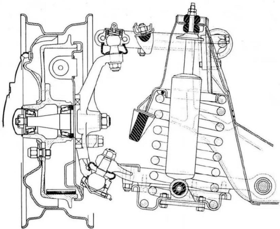
natural_image
Technical line drawing of a mechanical assembly with no visible text or symbolsFig.11.1. Sectioned view of front suspension assembly (drum brakes)
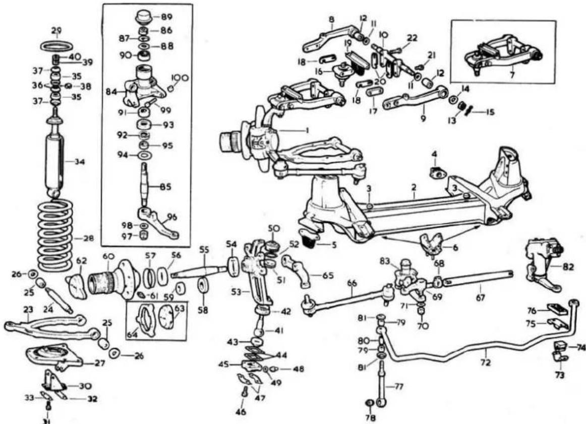
FIG.11.2. FRONT SUSPENSION ASSEMBLY
1 L.H. front suspension assembly
2 Front suspension cross-member
3 Rubber plug
4 Rubber mounting
5 Bump stop
6 Rubber mounting
7 Upper wishbone
8 Upper wishbone lever
9 Upper wishbone lever
10 Fulcrum shaft
11 Distance washer
12 Rubber bush
13 Slotted nut
14 Special washer
15 Split pin
16 Ball joint
17 Distance piece
18 Shim
19 Rebound stop
20 Shim (camber angle)
21 Bolt (short)
22 Bolt (long)
23 Lower wishbone lever
24 Fulcrum shaft
25 Bush
26 Special washer
27 L.H. seat assembly
28 Front suspension coil
29 Packing ring
30 Bracket
31 Setscrew
32 Tab washer
33 Tab wesher
34 Front shock absorber
35 Rubber buffer
36 Inner washer
37 Outer washer
38 Spacing collar
39 Nut
40 Locknut
41 Ball pin
42 Spigot
43 Railko socket
44 Shim
45 Cap
46 Bolt
47 Tab washer
48 Grease nipple
49 Washer
50 Rubber gaiter
51 Plastic insert
52 Ring
53 Stub axle carrier
54 Water deflector
55 Stub axle shaft
56 Oil seal
57 Water deflector
58 Inner bearing
59 Outer bearing
60 L.H. front hub
61 Grease nipple
62 L.H. hub cap
63 L.H. hub cap
64 Tool for removing/fitting hub caps
65 L.H. tie rod lever
66 L.H. outer tie rod
67 Tie rod tube
68 Clamp
69 End assembly
70 Nut
71 Special washer
72 Anti-roll bar (heavy duty)
73 Bracket
74 Rubber bush
75 Keeper plate
76 Packing block
77 Link
78 Rubber bush
79 Rubber pad
80 Distance tube
81 Retaining washer
82 Steering box
83 Steering idler
84 Bracket
85 Idler spindle
86 Nut
87 Tab washer
88 'D' washer
89 End cap
90 Bearing
91 Bearing
92 Felt seal
93 Retainer
94 Abutment washer
95 Abutment ring
96 Idler lever
97 Nut
98 Washer
99 Setscrew
100 Nut

natural_image
Technical line drawing of a mechanical assembly with no visible text or symbolsFig.11.3. Rear suspension arrangement

natural_image
Technical line drawing of a vehicle suspension system with chassis, frame, and suspension components (no text or labels)Fig.11.4. Steering layout

natural_image
Technical line drawing of automotive suspension system components including brake and wheel assembly (no text or labels)Fig.11.5. Removing the front suspension assembly

Fig.11.6. Packing piece to support wish-bone levers
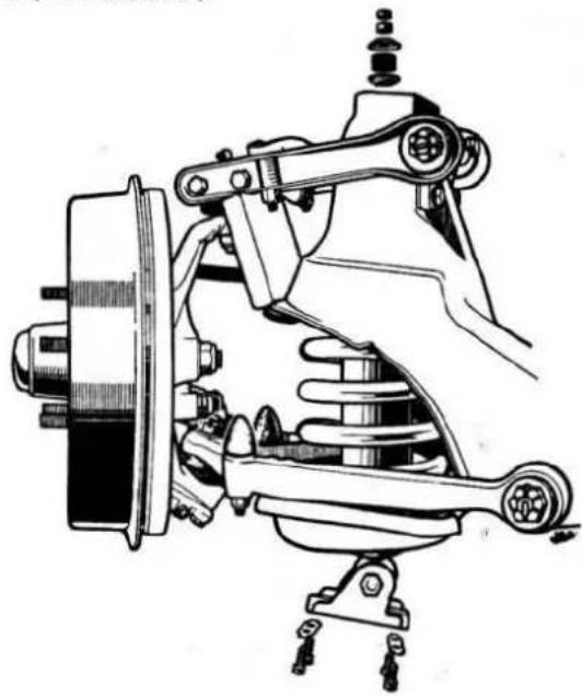
natural_image
Technical line drawing of a mechanical assembly with springs and levers (no text or symbols)Fig.11.7. Removal of damper. Packing piece in position

Fig.11.8. Location of distance piece on damper
all the necessary equipment. Any attempt to remove, or replace, these springs using unsuitable equipment could result in a serious accident.
Springs are marked with coloured paint to denote those of the same static load (this will probably be gone with age) it is essential, that springs fitted to a car are of the same colour coding. Packing pieces may be fitted above the coil springs of some cars to accommodate variations in the length so when ordering new springs, enquire also about packing pieces and their thickness for your particular model.
1 Remove the hydraulic damper as described in Section 3.
2 Detach the anti-roll bar link arm from the bracket at the rear edge of the spring pan.
3 Insert a suitable, and serviceable, coil spring compressor through the centre of the spring and compress the spring to relieve the load on the seat pan screws (Fig.11.9).
4 Remove the six setscrews with their spring washers securing the seat pan to the lower wishbone.
5 Unscrew the compressor until the load on the spring is relieved completely. The coil spring and the seat pan now can be removed.
6 Refitting is the reverse procedure but alignment of the seat pan holes with their counterparts in the lower wishbone will be made easier if pilot studs 8" (20 cm) in length with one end threaded 3/8" UNF are fitted as shown in Fig.11.10. Take note of the necessity for fitting similar coded springs and, possibly, packing pieces.

natural_image
Technical line drawing of a mechanical assembly with springs and housing (no text or symbols)Fig.11.9. Compressing the coil spring
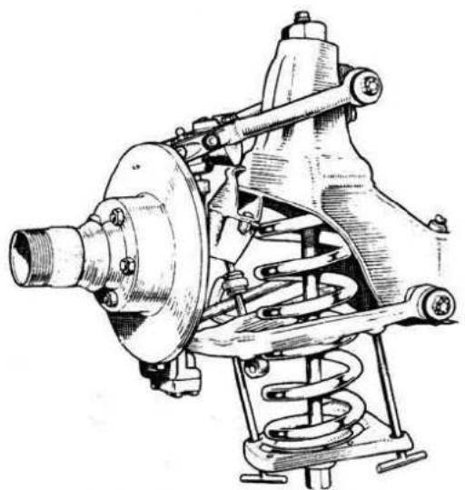
natural_image
Technical line drawing of a mechanical assembly with springs and housing (no text or symbols)Fig.11.10. Aligning the seat pan holes
5 Front wheel hub - removal, dismantling and refitting
1 Jack up the car to remove the front road wheel. Support the car on firmly based axle stand.
2 Refer to Chapter 9 and remove the brake caliper from the front stub axle carrier.
3 Take out the split pin locking the hub nut. On cars with disc brakes it will first be necessary to prise off the end cap in order to get at the split pin and the retaining nut. The split pin is accessible through a hole in the hub of cars with wire wheels.
4 Remove the slotted nut, and the plain washer behind it, from the end of the stub axle shaft.
5 Withdraw the hub from the stub axle shaft by hand.
6 To dismantle the hub, first extract the grease seal and then withdraw the taper roller bearings. If new bearings are to be fitted the old ones can be drifted out using the grooves provided in the abutment shoulders in the hub.
7 Refitting is the reverse of the removal procedure.
8. First repack the bearing with high melting point grease, do not pack the hub with grease but apply a coating to the inside of the hub between the outer races of the bearings and apply a light coating of grease to the stub axle shaft. Do not fill the end cap with grease. Later cars are fitted with a front hub grease nipple so the foregoing can be done after assembly if desired but care should be taken not to overlubricate the hubs as this may cause the seal to "blow". Stop pumping in grease when it starts to come out of the bleed hole in the end of the dust cap.
9 The end float of the wheel bearings must be checked after assembly and before the split pin is fitted to the hub securing nut.
10 The correct end float of the bearing is 0.003" to 0.005" (0.07 to 0.13 mm). On cars fitted with disc brakes it is most important that it does not exceed 0.005" otherwise the brakes may tend to drag and not function properly.
11 The end float can be checked with a Dial Test Indicator mounted with its plunger against the hub. Tighten the nut until lateral movement of the hub is within limits and then lock the nut with a new split pin.
12 An alternative method of adjusting the end float is to tighten down on the nut until slight restriction to rotation of the hub is felt. Now slacken the nut between one and two flats (depending on alignment of the split pin hole with a slot in the nut) and check that the hub is now free. It is advisable to fit the wheel and make sure that it spins freely. If satisfactory, remove the wheel and fit a new split pin.
13 When refitting the brake caliper do not overlook the necessity for checking its clearance with the disc (see Chapter 9).
14 Bleed the brake system when reassembly is completed.

natural_image
Technical line drawing of a mechanical assembly with exploded view (no text or labels)Fig.11.11. Exploded view of the front wheel hub
6 Stub axle carrier and lower wishbone ball joint - removal, adjustment and refitting
1 Take the weight of the car under the lower wishbone lever and remove the road wheel. As a safety measure, place a stout block at any convenient point on the chassis to support the car in the event of the jack slipping.
2 Remove the front wheel hub as described in Section 5.
3 Refer to Fig.11.12.
4 Undo and remove the self locking nuts and plain washer which secures the upper ball joint to the stub axle carrier.
5 Remove the nut securing the lower ball joint to the wishbone.
6 The stub axle carrier is now held in position by the grip on the taper of the ball joints. To release them, strike the stub axle carrier several sharp blows with a hammer adjacent to the upper ball joint and follow this by striking the lower wishbone as close as possible to the ball joint. If the ball joints are not released by that action you will have to resort to drifting out the joints.
7 The stub axle carrier will come away complete with the lower ball joint. To separate them, first release the wire clip holding the rubber gaiter in place and then remove the gaiter and the plastic insert below it.
8 Knock back the tabs of the locking plates and take out the four bolts securing the ball pin cap to the stub axle carrier, note the shims under the cap. Lift off the cap complete with the Railko socket inside it, the ball pin and the spigot.
9 Reassembly of the ball joint to the stub axle carrier is the reverse of the removal procedure but the ball joint, if a new item is being fitted, must be shimmed to give clearance of 0.004" to 0.006" (0.10 to 0.15 mm). It is not permissible. to remove the shims to take up wear in the ball pin and socket. If wear is present in these items they should be replaced.
10 Shims for adjusting the ball joint are available in 0.002" (0.05 mm) and 0.004" (0.10 mm) thicknesses. To adjust the clearance, assemble the ball pin to the stub axle carrier together with shims so that when the ball cap is fully tightened, the ball pin is tight in its socket. Now fit additional shims to a value of between 0.004" to 0.006" (0.10 to 0.15 mm) and this should allow the shank of the pin to be moved by hand without any perceptible play.
11 Use new locking plates to secure the ball pin cap bolts and knock up the tabs to lock the bolts.
12 Refit the stub axle carrier in the reverse order to that in which it was removed not forgetting to check the end float of the wheel hub and the clearance of the brake calipers.
13 Using a grease gun, pump grease into both ball joints.
14 Finally bleed the brake system and refit the road wheel.
7 Lower wishbone - removal, replacement of bushes and refitting
1 Remove the coil spring in the manner described in Section 4

FIG.11.12. THE STUB AXLE CARRIER & LOWER WISHBONE BALL JOINT
1 Self locking nut 8 Railko socket
2 Washer 9 Shims
3 Rubber gaiter 10 Cap
4 Securing ring 11 Washer
5 Plastic insert 12 Grease nipple
6 Spigot 13 Tab washer
7 Ball pin 14 Securing bolts
but your attention is first drawn to the warning at the beginning of that Section.
2 Remove the nut and washer securing the ball joint to the wishbone and tap the wishbone smartly with a hammer to break the grip of the taper at the ball joint. Now try to lift the wishbone off the lower ball joint. If you cannot get enough movement on the stub axle carrier to allow the wishbone to swivel clear, completely remove the stub axle carrier.
3 Take out the split pin and remove the slotted nut from one end of the fulcrum shaft. Take off, and retain, the special washer which will be found under the nut.
4 Replace the nut and screw about halfway onto the shaft, now drive the shaft out from that end unscrewing the nut as necessary to allow the shaft to move. Finally, use a punch to drift the shaft right out but be careful not to damage the thread. Remove the wishbone.
5 The old bushes can be drifted out, or preferably pressed out, from the wishbone eyes but when doing this, support the wishbone on the eye from which the bush is being removed.
6 Lubricate the new bush with soapy water (a 12:1 solution is adequate) and press it into the eye until it projects from each side an equal amount.
7 Refitting is the reverse of the above but for the time being leave the slotted fulcrum nut finger tight.
8 After refitting the roadwheel, lower the car until full weight is taken on the wheel. Move the car to position the front wheels to give access to the fulcrum nut, fully tighten it and fit and open a new split pin. Tightening of the fulcrum nut when the car is not in the normal riding position will result in undue torsional loading of the rubber bushes and will probably lead to premature failure.
8 Upper wishbone and upper wishbone ball joint - removal, replacement of bushes and refitting
1 Take the weight of the car under the lower wishbone lever and remove the roadwheel. As a safety measure, place a stout block at any convenient point under the chassis to support the car in the event of the jack slipping.
2 Tie up the stub axle carrier to the subframe because, when the ball joint is disconnected, it will rotate outwards and damage to the flexible hose may result.
3 Refer to Fig.11.13. Remove the nuts from the two bolts securing the ball joint to the upper wishbone lever and remove the bolts, taking extreme care to collect the shims and distance piece from each side of the ball joint. The shims from each side must be kept together and replaced in their original positions because they control the castor angle.
4 If the upper ball joint only is to be removed, undo the nut securing it to the stub axle carrier and strike the carrier several sharp blows with a hammer to break the grip of the ball joint taper. Lift out the ball joint. If wear is present in the joint a new assembly will have to be fitted.
5 The upper wishbone ball joint can be left in position if it is the wishbone which has to be removed.
6 Remove the four set bolts securing the wishbone fulcrum shaft to the suspension cross member turret. The wishbone assembly can now be removed but take careful note of the relative positions of the shims between the turret and the fulcrum shaft brackets as these control the camber angle and must be replaced in the position from which they were removed (Fig.11.14).
7 Remove the nuts, bolts and the distance pieces securing the rebound stop brackets to the wishbone levers.
8 Take out the split pins and remove the slotted nuts which secure the levers to the fulcrum shaft. Work the levers off the shaft.
9 Drift out, or preferably press out, the bush from the eye of the wishbone lever.
10 Lubricate the new bush with soapy water (a 12:1 solution is adequate) and press it into the eye of the lever until it projects from each side an equal amount.
11 Reassemble the wishbone levers in the reverse manner to
their dismantling but leave the slotted nuts securing the levers to the fulcrum shaft finger tight at this stage.
12 Refit the upper wishbone assembly and the upper wishbone ball joint, if applicable, in the reverse manner to the dismantling procedure but do ensure that the shims are refitted correctly otherwise, as already mentioned, the castor and camber angles will be upset.
13 After refitting the roadwheel, move the car to turn the wheels to a convenient position to give access to the slotted nuts of the upper wishbone fulcrum shaft. Tighten the nuts and fit, and open, a new split pin. Tightening of the fulcrum nuts when the car is not in the normal riding position will place undue torsional loading on the rubber bushes and may lead to their premature failure.

natural_image
Technical line drawing of a mechanical assembly with springs and bolts (no text or symbols)Fig.11.13. Removing the upper wishbone lever ball joint

natural_image
Technical line drawing of a mechanical assembly with bolts and brackets (no text or symbols)Fig.11.14. Location of shims controlling the camber angle
9 Anti-roll bar - removal, refitting and replacement of rubber bushes (Fig.11.15)
1 Place the car over a pit or raise it, making sure that it is adequately supported, to give access to the anti-roll bar.
2 Remove the self locking nut and drift out of the bolt attaching the link arms to the right and left hand coil spring seat.
3 Remove the two bolts securing each support bracket to the chassis side member and remove the anti-roll bar.
4 The only faults likely to arise with the anti-roll bar components are deterioration of the rubbers and, as experience has shown, wear on the centre hole of the lower rubber pad retaining washer allowing it to work down over the shoulder on the link arm. In extreme cases the shoulder on the link arm may also be worn.
5 You will find it possible to replace individual rubbers without removing the whole assembly.
6 To replace the bracket rubbers (item 4 in Fig.11.15). Raise the front of the car and support it firmly. Remove the two bolts securing each bracket, remove the brackets and pull down on the
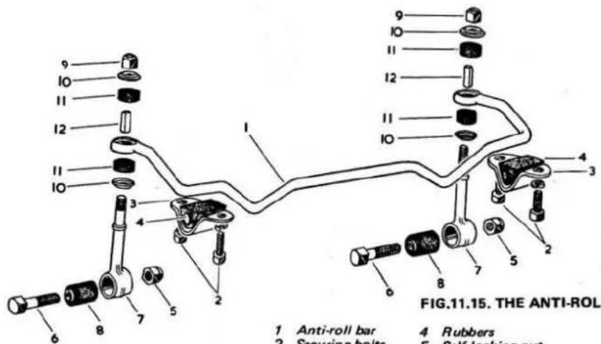
FIG.11.15. THE ANTI-ROLL BAR ASSEMBLY
1 Anti-roll bar
2 Securing bolts
3 Support brackets
4 Rubbers
5 Self locking nut
6 Bolt
7 Link arm 10 Cup washers
8 Rubber bush 11 Rubbers
9 Nut 12 Spacer
bar and remove the rubbers by springing them over the bar. Fit the new rubbers and replace the brackets with the bolts finger tight. Lower the car to take the full weight on the wheels and then tighten up on the bracket bolts.
7 To replace the upper and lower cup washers and rubbers (items 10 and 11 in Fig.11.15) first remove the self locking nut at the top of each link arm and then push upwards on the bar to clear the link arm. If you cannot get sufficient movement of the bar to clear the link arm, slacken the bolts to the brackets on the chassis side members. The cup washers and rubbers can be lifted off when the bar is clear of the link arm new items can be fitted but do not overlook replacement of the spacer and the necessity for the full weight of the car to be taken on the wheels before tightening the bracket bolts.
8 To replace the link arm bush, first take off the self locking nut at the top of the link arm then remove the self locking nut

from the bolt attaching the link arm to the coil spring seat. Drift out the bolt and remove the link arm. Drift, or preferably press, out the bush from the link arm eye, lubricate the new bush with a soap and water solution and press it into position in the eye so that it projects an equal amount on each side. Refit the link arm in the reverse order to the above.
9 Refitment of the whole assembly is the reverse of the removal procedure but the support bracket bolts on the chassis side members must not be fully tightened until the full weight of the car is taken on the wheels.
10 Accidental damage to front suspension components
The dimensioned drawings at Figs.11.16, 17,18 and 19 are provided to enable you to assess the dimensional serviceability of front suspension components following accidental damage to your car. Be sure to check, in addition for fractures and deterioration.

Fig.11.16. Lower wishbone

Fig.11.17. Stub axle carrier

Fig.11.18. Upper wishbone lever (pressed steel type)


Fig.11.19. Upper wishbone lever (forged type)
11 Rear road springs - general
An exploded view of the rear suspension assembly is given at Fig.11.20 to which reference should be made when carrying out work described in the following Sections.
Should a spring have weakened considerable or failed and a new one has to be fitted, they must be renewed in pairs as the remaining spring will have taken a "set" and unless the springs have the same performance and characteristics, road holding and ride can be affected adversely.

FIG.11.20. EXPLODED VIEW OF THE REAR SUSPENSION
1 Rear road spring
2 Front mounting pad
3 Front mounting plate
4 Centre clamping plate
5 Torque arm
6 Panhard rod
7 -Adjusting piece
8 -Locknut
9 -Rubber buffer
10 -Distance tube
11 -Outer washer
12 -Inner washer
13 Hydraulic damper
14 -Rubber buffer
15 -Inner washer
16 -Outer washer
17 —Securing nut
18 -Locknut
12 Rear road spring - removal and refitment
1 Jack up the car under the rear axle and place a stand under the chassis member just forward of the front mounting point of the spring. Place a wooden block between the stand and the body to distribute the load and then lower the car onto the stand.
2 Remove the road wheel to improve access to the spring.
3 Place a jack under the eye of the spring and raise it to relieve pressure on the centre mounting clamp plate.
4 Remove the four nuts and bolts securing the centre mounting clamp plate and remove the plate.
5 Unscrew the nut from the spring eye bolt and drift out the bolt taking care not to damage the thread.
6 Lower the jack and the spring can now be withdrawn from the front mounting plate.
7 Refitting the spring to the car is the reverse of the above but do not tighten the spring eye bolt until the weight of the car is taken on the wheel otherwise undue torsional loading of the rubber bush will result and may lead to premature failure.
13 Centre mounting rubber and replacement
1 The centre mounting rubbers are bonded to plates which are
attached to the top and bottom of the spring by the centre bolt. (Fig.11.21).
2 Remove the rear spring as described in Section 12.
3 Place the spring in a vice and hold it as close to the centre mounting rubbers as possible.
4 Undo the nut from the centre bolt, drift out the bolt from the spring leaves and collect the spacing washer from the recess in the main leaf. The two mounting rubbers can now be detached.
5 Place the new rubbers in position on the spring with the spacing washer between the main leaf and the lower mounting.
6 Refit the centre bolt with its plain washer and tighten down securely on the nut.
7 Remove the spring from the vice and refit to the car in the manner described in Section 12.
14 Front mounting rubbers - removal and refitting
1 Remove the rear spring as described in Section 12.
2 Unscrew the self locking nut securing the rubber mounting to the main leaf and remove the rubber mounting.
3 Refitting is the reverse of the above.
4 Replace the rear road spring as described in Section 12.

natural_image
Cross-sectional diagram of a mechanical assembly with layered components (no text or symbols)Fig.11.21. Section through spring centre bolt
15 Spring eye bush - removal and refitting
1 Remove the rear road spring as described in Section 12.
2 Drift, or preferably press, out the rubber steel bonded bush from the eye of the spring.
3 Lubricate the new bush with a soapy water solution and press it into position in the eye so that it projects an equal amount each side of the spring.
4 Refit the spring to the car as described in Section 12.
16 Torque arm - removal and refitting
1 Place the car over a pit or raise the rear of the car to give access to the torque arm. Make sure that the car is adequately supported before doing any work underneath it.
2 Remove the self locking nuts of the bolts securing the torque arm to the bracket on the rear axle and on the body.
3 Drift out the bolts making sure that you do not damage the thread and remove the torque arm.
4 Refitting is the reverse of the above.
17 Hydraulic dempers (rear) - removal and refitting
1 Remove the floor of the luggage compartment. The nuts securing the top of the dampers will be soon at the right and left hand side of the compartment.
2 Remove the two nuts and the rubber buffer and washers from the top of the damper.
3 Place the car over a pit or raise the rear of the car to give access to the dampers. Make sure that the car is adequately supported before doing any work underneath it.
4 Remove the two nuts and the inner and outer washers and the rubber buffer from the damper attachment bracket on the rear axle.
5 Compress the damper until it can be removed from the mounting and collect the remaining washers and rubber buffers.
6 There is no provision for adjustment or "topping up" of the damper so if it is faulty a new item must be fitted.
7 Before fitting a new damper, hold the damper in its normal vertical position with the shroud uppermost and make several short strokes (not more than halfway) until there is no lost motion and then extend the damper to its full extent once or twice. This will bleed any air from the pressure chamber that may have accumulated due to the damper having been stored in a horizontal position.
8 After completing the operation at paragraph 7, refit to the car in the reverse order to the removal sequence.
18 Panhard rod - removal, refitting and adjustment
1 Place the car over a pit or raise the rear of the car to give access to the panhard rod. Make sure that the car is adequately supported before doing any work underneath it.
2 Remove the nut at each end of the rod and take off the rubber buffer and washers.
3 Loosen the locknut and screw it along to the end of the thread.
4 Screw the adjusting piece into the panhard rod tube, by means of a spanner on the flats, until the rod can be disconnected from the mounting brackets.
5 When refitting the rod, first screw the adjusting piece into the rod tube and then fit one rubber buffer with a distance piece and inner and outer washers at each end of the rod.
6 Offer the rod to the mounting brackets and screw out the adjusting piece until the rod is retained in the brackets.
7 The car must now be lowered so that its full weight is on the wheels.
8 Fit the inner washer, the rubber buffer and the outer washer to the bracket at the rear axle and fit the nut but do not tighten fully as yet.
9 Fit the inner washer, the rubber buffer and the outer washer at the body bracket end of the rod. Hold the adjusting piece with a spanner on the flats and fit and tighten down on the securing nut.
10 Now refer to Fig.11.22 for adjustment of the panhard rod. 11 Both rear tyres must be of the same type and of the same pressure.
12 Place a straightedge across one rear tyre and measure the distance from the straightedge to the flange of the chassis side member between the two bolts on the member as shown at "A" in Fig.11.22. Repeat for the other side of the car.
13 Dimensions "A" must be the same in each case. If they are not, adjust the length of the rod until they equalise.
14 Now fully tighten the securing nut at the rear axle bracket and recheck the adjustment. If dimensions are still equal screw up the locking nut to lock the adjusting piece to the panhard rod tube.
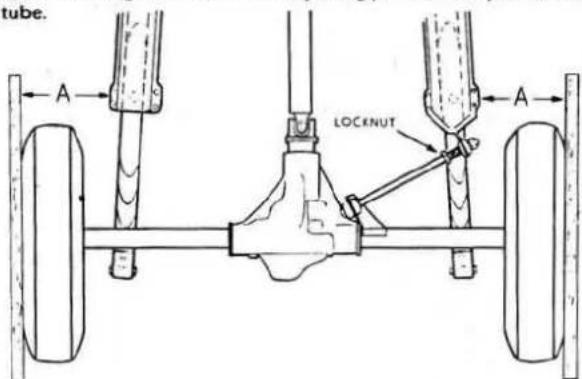
Fig.11.22. Adjustment of the panhard rod
19 Steering wheel - removal and refitting
1 Disconnect the battery.
2 Paragraphs 3 - 13 (inclusive) refer to Mk 1 cars.
3 Remove the four grub screws from the steering wheel hub.
4 Withdraw the horn push assembly and remove the eyelet from the horn wire contact.
5 Bend back the tab washer locking the steering wheel securing nut. Hold the steering wheel to stop it turning and remove the nut securing it to the inner column.
6 Pull upwards on the steering wheel to remove it from the splines on the inner column shaft. Before removal, note its position in relation to the road wheels.
7 Remove the two cup washers and the telescopic dust cover which are located on the inner shaft under the steering wheel.
8 Remove the two halves of the split cone from the inner shaft.
9 To refit the steering wheel, first place the two halves of the split cone in position making sure that the narrowest part of the cone is towards the top of the column.
10 Fit the lower cup washer followed by the telescopic dust cover and the upper cup washer. Whilst holding those items in position, slide the steering wheel onto the splines in the same position as before removal. The wheel should slide onto the splines quite easily, do not force it if it does not immediately enter the splines.
11 Fit the plain washer and a new tab washer over the inner column thread and fit the nut. Tighten down on the nut at the same time holding the steering wheel from turning. Turn over the tab to lock the nut.
12 Refit the eyelet to the horn wire contact and refit the horn push assembly.
13 Reconnect the battery and test the horn for correct operation.
14 The following paragraphs refer to Mk 2 and later cars.
15 Unscrew the four setscrews securing the horn ring cover to the steering wheel and remove the horn ring assembly.
16 On later cars, the horn ring cover attaches to the horn ring by spring loaded studs and on this type the cover is removed by an upward pull. The horn ring is attached to three studs on the steering wheel by nuts. Remove the nuts and lift off the horn ring but be careful not to lose the small washers under the nuts and the springs and washers over the studs under the horn ring.
17 Remove the eyelet from the horn wire.
18 Undo the locknut and the nut securing the steering wheel to the inner column and remove them.
19 Take note of the position of the steering wheel in relation to the road wheels and remove it from the inner column by a sharp upward pull.
20 Collect the two halves of the split cone from the inner column.
21 When refitting the steering wheel, first place the two halves of the split cone in position so that the narrowest part of the cone is towards the top of the column.
22 Whilst holding the split cone in position, slide the steering wheel onto the splines of the inner column in the same position as before removal. The wheel should slide onto the splines quite easily, do not force it if it does not immediately enter the splines.
23 Fit the plain washer to the inner column followed by the securing nut. Tighten down on the nut at the same time holding the wheel from turning. Fit the locknut.
24 Refit the eyelet to the horn wire and refit the horn ring and its cover.
25 Reconnect the battery and test the horn for correct operation.
20 Steering box (standard) - removal
1 Remove the nut and take out the pinch bolt which locks the lower steering column to the upper column.
2 Remove the screws securing the two halves of the switch covers at the centre of the steering wheel and separate them to clear the indicator and the transmission selector lever (if applicable) (photo 27.5).
3 On those cars with automatic transmission, remove the four drive screws and washers securing the piece of dash casing just above the steering column to gain access to the gear selector adjustment rod. Lift out the ball joint on the crank lever.
4 Carefully pull up on the steering wheel to move the inner column just a sufficient amount for the splines to clear the universal joint (photo 27.10).
5 If the car is not already over a pit, raise the front to gain access to the steering unit. Make sure that the car is well supported before doing any work underneath it.
6 If desired, the lower steering column may now be removed from the steering box. Turn the wheels to bring the pinch bolt into a favourable position, unscrew the nut and remove the pinch bolt and then pull the lower steering column off the
splines of the steering box.
7 Take off the self locking nut and the plain washer securing the track rod end to the drop arm.
8 Strike the drop arm smartly several times with a hammer, at the same time levering up on the track rod, to release the taper holding the track end to the drop arm (photo).
9 Knock back the tabs locking the four steering unit bolts which attach it to the front suspension. Remove the bolts and lift off the steering unit.

natural_image
Close-up of a mechanical component with textured surfaces and no visible text or symbols20.7. Track rod end released
21 Steering box (standard) - dismantling
1 First thoroughly clean the exterior of the steering box. 2 Refer to the exploded view of the steering box at Fig.11.23. 3 Remove the drain plug and drain the oil from the box. Do not confuse the drain plug with the rocker shaft adjustment screw (photo).
4 Remove the four set bolts and the spring washers securing the rocker shaft cover plate and remove the plate (photo). Take care not to lose the spring from the rocker shaft adjustment screw.
5 Remove the roller from the top of the main nut.
6 Take off the nut securing the drop arm to the rocker shaft.
7 Refer to Fig. 11.24 and take careful note of the position of the alignment marks so that the arm is fitted in the correct position on reassembly.
8 Using a suitable extractor, remove the drop arm from the spline on the rocker shaft (photo). Under no circumstances must the drop arm be hammered off as this will cause damage, through indentation to the balls.
9 Withdraw the rocker shaft from the top of the box (photo). 10 Take out the "C" ring from the bottom of the box.
11 Remove the four set bolts and the washers securing the upper end plate to the steering box. Remove the plate and note the gasket and the shims underneath it (photo).
12 Push the worm shaft outwards and withdraw the outer race of the upper bearing (photo). The ten balls of the race will come out at the same time; take care not to lose them.
13 Unscrew the worm from the worm nut and take it out of the unit (photo).
14 Take out the four set bolts attaching the end plate to the bottom of the box noting the shims, gasket and distance piece underneath it. Withdraw the outer race of the lower bearing and collect the ten balls being careful not to lose them.
15 Knock back the tabs locking the two setscrews securing the transfer tube to the main nut, remove the screws and take off the tube with the thirty one balls if these have not already run out.
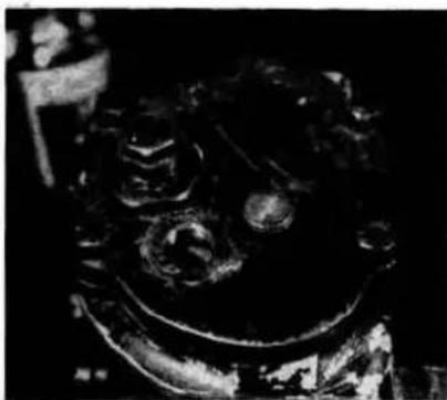
natural_image
Close-up of a mechanical component with no visible text or symbols21.3. Filler/level plug
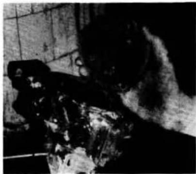
natural_image
Black-and-white photo of a person in motion, possibly a robot or robotic arm, with no visible text or symbols.21.4. Removing the cover plate

natural_image
Black-and-white photo of mechanical components or tools, possibly a tool set or assembly (no visible text or symbols)21.8. Removing the drop arm

natural_image
Black-and-white photo of a person operating a mechanical device (no visible text or symbols)21.9. Removing the rocker shaft

natural_image
Close-up of hands holding a dark, textured object with no visible text or symbols21.11. The end plate and shims
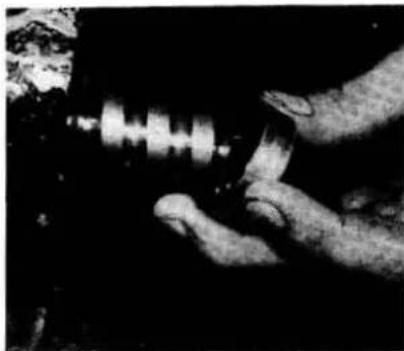
natural_image
Close-up of hands performing a dental procedure on teeth (no visible text or symbols)21.12. Withdrawing the upper bearing
natural_image
Cross-sectional view of a mechanical component with internal cavities and mounting holes (no visible text or symbols)21.13a. The worm and nut

Fig.11.24. Alignment marks on rocker shaft and drop arm

natural_image
Close-up of a mechanical component with no visible text or symbols21.13b. Removing the nut

FIG.11.23. THE STANDARD STEERING BOX
1 Steering box
2 Trunnion bush
3 Inner column worm
4 Main nut
5 Roller
6 Steel balls
7 Ball race
8 Distance piece
9 End plate (bottom)
10 Gasket
11 End plate (top)
12 Oil seal retainer plate
13 Oil seal
14 Gaskets
15 Shims
16 Setscrew
17 Spring washer
18 Rocker shaft
19 'O' ring
20 Washer
21 Drop arm
22 Nut
23 Spring washer
24 Cover plate
25 Gasket
26 Setscrews
27 Spring washer
28 Rocker shaft adjustment
screw
29 Locking nut
30 Spring
31 Spring tension bolt
32 Oil filler plug
33 Washer
34 Bolt (long)
35 Bolt (short)
36 Tab washer
22 Steering box (standard) - examination
23 Steering box (standard) - reassembly

natural_image
Close-up of a dark, irregularly shaped mechanical component with mounting holes and central bore (no visible text or symbols)
22.1a. Damage to top cover
23.5. Assembly of worm and nut


natural_image
Close-up of a mechanical component with internal cavities and mounting holes (no visible text or symbols)
natural_image
Close-up of a dark, elongated object with a reflective surface, possibly a mechanical component or tool (no visible text or symbols)
22.1b. Wear on rocker shaft
23.10. Final assembly of components
natural_image
Close-up of a mechanical component with internal cavities and mounting holes (no visible text or symbols)in the bottom race remain in position (photo). Feed the shaft until the nut is halfway along it.
6 Coat the top race and the balls with light grease and assemble to the top of the box together with the shims as removed with a gasket at each side of them.
7 Slide the "O" ring oil seal over the end of the shaft and press it into position. It is a good tip to cover the splines of the shaft with adhesive tape to prevent damage to the seals by the splines.
8 Offer the end plate to the box and secure it in position with the four bolts.
9 Assemble the rocker shaft and engage the slotted extension with the main nut.
10 Fit the roller to the top of the main nut to give the assembly shown (photo).
11 Fit the cover plate gasket, fit the cover plate and secure with the four bolts.
12 Fit the drop arm to the rocker shaft making sure that the splines mate correctly and that the scribed line on the rocker shaft matches the correct line on the drop arm (see Fig.11.24).
24 Steering box (standard) - adjustment of wormshaft end float
1 The wormshaft bearings should be adjusted to a preload of 0.002" to 0.003" (0.05 to 0.08 mm) by adding or subtracting shims as necessary at each end of the box. The shims are 0.005" (0.13 mm) in thickness and the gaskets are 0.003" (0.08 mm) thick.
2 Remove the bolt (31 in Fig.11.23) and the spring underneath it and unscrew the rocker shaft adjustment screw (28 in Fig.11.23) until it is fully clear of the rocker shaft.
3 Eliminate all feel of play in the worm shaft by removing shims or gaskets, if more than two at each end are fitted, as may be necessary, always maintain one gasket at each side of the pack of shims.
4 Now check that the worm shaft turns freely by fitting the lower steering column and rotating the shaft. If there is any tightness fit another gasket, make sure there is no undue end float of the wormshaft and try once again for freedom in rotation.
25 Steering box (standard) - adjustment rocker shaft end float
1 This work can be done when the steering box is in position on the car but access to the locking nut and to the spring tension
bolt is rather restricted.
2 If the work is being done with the box in position on the car, make sure that the wheels are in the straight ahead position. If you have the box on the bench, halve the number of turns the wormshaft makes from lock to lock to obtain the centre position of the nut.
3 Unscrew the spring tension bolt (item 31 in Fig.11.23) and take out the spring.
4 Slacken the locknut (item 29 in Fig.11.23) and screw down on the adjuster screw by hand until it contacts the rocker shaft.
5 Hold the adjuster screw from turning and screw down on the locknut.
6 Now test for freedom of movement of the wormshaft, if there is any tightness at the centre of travel the rocker shaft enc float will have to be readjusted.
7 Refit the spring followed by the retaining bolt.
26 Steering box (standard) - refitment
Refitting the steering box to the car is the reverse of the removal procedure but when reassembling the upper steering column to the lower column make sure that the position of the steering wheel in relation to the road wheels is the same as before removal. Before tightening the top socket pinch bolt of the lower steering column, fully depress the upper half of the universal joint and then raise it by 14 " (6 mm) and tighten in that position.
27 Steering column - removal
1 Disconnect the battery.
2 Unscrew the bezels which hold the speedometer trip and the clock cables to the dash casing.
3 Remove the four screws and washers securing the dash casing.
4 Disconnect the wires to the flashing indicator and the head-lamp flasher, at the snap connectors. Detach the horn wire from the connector lower down the steering column and, if overdrive is fitted, disconnect the wires from the overdrive switch snap connector at the top part of the column.
5 Remove the screws and washers which secure the two halves of the switch covers below the steering wheel and place them clear of the flashing indicator lever and the transmission selector lever if the car is an automatic model (photo).
6 If the car is fitted with automatic transmission, unscrew the ratchet on the adjustment rod and lift out the ball from the joint
on the crank lever.
7 Now open the bonnet and move the car to bring the wheels to a favourable position for removal of the lower steering column pinch bolt and nut. Remove the nut and the pinch bolt securing the lower steering column to the upper column.
8 On later cars, a jubilee clip secures the upper steering column to a flange where the column passes through the body. Undo the jubilee clip. (photo).
9 Support the steering column and remove the two set bolts which attach it to the bracket on the dash.
10 Lift upwards on the steering column to disconnect it from the splines of the lower column (photo). It may be helpful at this point to have an assistant lightly tap the lower column with a hammer to help in separating it but this is not usually necessary.
11 Lift out the steering column and collect the rubber cup from the bottom end of the column.
28 Steering column - dismantling
1 Steering columns of early and later model cars differ slightly but the procedure for dismantling is very similar.
2 Refer to Fig.11.25 which gives an exploded view of a typical steering column assembly.
3 Remove the steering wheel in the manner described in Section 19.
4 Withdraw the inner column from the outer column.
5 Take out the two screws with their serrated and plain wasbers which hold the flashing indicator striker in position.
6 Take off the circlip from the end of the horn wire contact nipple and remove the washer, spring and rubber.
7 Remove the split collet (item 23 in Fig.11.25).
8 Unscrew and remove the centre button which retains the inner column shaft. Remove the shaft.
9 Carefully prise up the horn pick-up ring serrations and slide the ring off the rubber rotor (items 37 and 38 in Fig.11.25).
10 Separate the two halves of the rotor at the same time disengaging the horn wire from the top half of the rotor.
11 Withdraw the horn wire.
12 Remove the two screws which secure the flashing indicator switch to the outer column.
13 If overdrive is fitted, remove the two nuts and bolts securing the overdrive switch to the outer column.
14 For those cars with automatic transmission, undo the circlip and slide it with the washer along the upper control rod.
15 Slacken the nut securing the upper control rod to the lower rod.
16 Remove the two nuts, bolts and the spacers which secure the
quadrant selector to the outer column bracket.
17 Remove the bolt, the plain and serrated washers securing the quadrant selector pointer to the bracket.
18 Pinch together one of the ends of the starter/reverse inhibitor switch control rod and withdraw the washer and the control rod.
19 Take out the upper and lower automatic transmission control rods from their bushes. On left hand drive cars, slide the lower cranked control rod off the outer column with its support bracket, after slackening the jubilee clip, and then separate the lower control rod from the supprt bracket.
20 Remove the bolt which holds the starter/reverse inhibitor switch.
21 Take out the nuts and bolt holding the earth contact.
22 Remove the nut and the bolt securing the two rubber contact holders, the fibre insulation strip and the contact.
23 Remove the felt bearings in the top and the bottom of the outer column by removing the spring clips and the washers. Some models may have nylon bushes instead of felt bearings, the bushes have studs which locate in holes in the outer column and are removed by pressing down on the studs, at the same time pulling outwards on the bush.
29 Steering column - reassembling
1 Figures in brackets refer to the items depicted in Fig.11.25.
2 Replace the two retaining washers (17) the felt washers (15 and 16) and the spring clips (18) in the top and bottom of the outer column.
3 Refit the two rubber contact holders (40) in the bracket at the lower end of the column.
4 Pass the bolt (42) through the contact (41), which should face towards the top of the column, through the fibre insulating strip (45) and secure with the nut.
5 Replace the earth contact (32) and secure it with its nut and bolt.
6 The following paragraphs refer to cars fitted with automatic transmission.
7 Slide the lower control rod through the lower bush. On left hand drive cars thread the rod through the hole in the steering column bottom support bracket.
8 Refit the support bracket and the jubilee clip and pass the lower control rod through the supporting bush on the side of the outer column.
9 Refit the selector quadrant securing it to the bracket by the two nuts and bolts, fit the spacers between the selector quadrant and the bracket.
10 Pass the upper control rod through the top bush on the outer column and now slide the plain washer and the circlip over the

natural_image
Close-up of mechanical components with no visible text or symbols27.5. Separate the switch covers
natural_image
Black-and-white photo of a person standing near a large structure with visible smoke or dust (no text or symbols)27.7. Jubilee clip securing steering column

natural_image
Dark, low-resolution image with indistinct shapes and no visible text or symbols27.10. Separating the upper and lower steering columns

FIG.11.25. TYPICAL STEERING COLUMN ASSEMBLY
| 1 | Lower column sub-assembly | 12 Universal joint end yoke | 24 Locknut | 37 Bottom half of rubber rotor |
| 13 Universal joint journal assembly | 25 Rubber seal | 38 Top half of rubber rotor | ||
| 2 | Rubber coupling | 26 Stone guard | 39 Eyelet | |
| 3 | Bolt | 14 Outer tube | 27 Split cone | 40 Contact holder |
| 4 | Locking nut | 15 Felt bearing | 28 Steering wheel | 41 Contact |
| 5 | Rubber bush | 16 Felt bearing | 29 Nut | 42 Bolt |
| 6 | Bolt | 17 Retaining washer | 30 Washer | 43 Nut |
| 7 | Nut | 18 Spring clip | 31 Locking nut | 44 Rubber sleeve |
| 8 | Spring washer | 19 Inner column | 32 Earth contact | 45 Fibre insulating strip |
| 9 | Universal joint end yoke | 20 Shaft | 33 Slip ring | 46 Striker peg |
| 10 | Universal joint journal assembly | 21 Stop button | 34 Cable | 47 Upper switch cover |
| 11 | Flange yoke | 22 Spring clip | 35 Contact | 48 Lower switch cover |
| 23 Split collet | 36 Spring |
rod.
11 Refer to Fig.11.26 and align the flat on the end of the upper control rod with the hole for the securing screw in the end of the lower control rod.
12 Join the upper and the lower control rods, fit the plain washer and secure the upper rod with the circlip.
13 Check that the upper and lower control rods are aligned and then tighten down on the bolt.
14 Assemble the quadrant selector pointer to its bracket and tighten down finger tight on its nut and bolt.
15 Refit the starter/reverse inhibitor switch finger tight to its bracket on the outer column.
16 Fit the rubber grommet to the crank lever on the lower control rod, pass the starter/reverse inhibitor wire through the grommet, fit the washer and open the ends of the control rod.
17 The following paragraphs again refer to all cars.
18 Refit thflashing indicator switch to the outer column.
19 If overdrive is fitted, refit the overdrive switch to the bracket on the outer column and secure with the two nuts, bolts and serrated washers.
20 Thread the horn wire (39) through the inner column by passing it through the upper rotor (38) and fit the upper half of the rotor with the groove towards the bottom of the column.
21 Fit the lower half of the rotor (37) and whilst holding them in position, slide on the horn pick-up ring with its serrations towards the bottom of the column. Knock or press down the serrations into the groove until the pick-up ring is secure.
22 Pass the inner shaft (20) over the horn wire into the inner column (19) so that the slot in the shaft splines aligns with the hole in the inner column. Screw in the centre button (21) until the inner shaft binds on the button and then slacken off until the inner shaft moves freely.
23 The indicator striker ring (46) should now be fitted with the
peg pointing towards the bottom of the column. Turn the inner column until the striker retaining bolts are in the vertical position and now set the striker peg so that it is just below the horizontal axis. Fit the two screws with the serrated and plain washers to secure the ring in position.
24 Slide the split collet (23) onto the inner shaft with the serrations towards the bottom of the column.
25 Carefully slide the inner column into the outer column, making sure that the peg of the indicator striker ring does not foul the contacts on the indicator lever.
26 Slide the rubber grommet, with the flange towards the top of the column, over the horn wire and the spring with the larger coils first, and the washer. Fit the circlip over the nipple.

natural_image
Technical line drawing of a mechanical assembly with a bolt and clamping tool (no text or symbols)Fig.11.26. Alignment of flat on upper control rod (automatic transmission)
30 Steering column - refitting
1 Ensure that the front wheels are in the same position as before removal of the column.
2 Fit the rubber cup (25) over the end of the steering column.
3 Ensure that the striker peg (46) is between the two cancelling arms on the flashing indicator lever.
4 Pass the steering column through the hole in the floor of the body and engage it with the splines on the lower steering column universal joint, restrain the inner column from being pushed up whilst engaging the splines.
5 On left hand drive cars fitted with automatic transmission, secure the bottom support bracket on the column to the body by means of the four bolts.
6 Offer the top mounting bracket to the studs on the body and secure with the two nuts and washers.
7 Refit the jubilee clip to the flange on the body at the bottom of the column and tighten up.
8 Refit the pinch bolt to secure the inner column to the lower column, fit the nut and tighten down.
9 On right hand automatic drive cars refit the ratchet adjustment onto the ball joint on the crank lever. Now, for right and left hand drive, move the hand control to the "D" position on the quadrant, match up the upper switch cover and move the pointer along the elongated slot in the outer column bracket until the pointer coincides with the "D" on the switch cover.
10 To ensure correct operation of the reverse light and starter cut-out inhibitor switch on automatic drive models, slacken the starter/reverse light inhibitor switch securing bolt. Move the gear selector lever to the "D" position. Move the starter/reverse light inhibitor switch until the hole in the lever is in line with the hole in the switch base plate. Maintain the holes in alignment by passing a piece of wire through them (Fig.11.27). Tighten the nut securing the switch to the upper column. Remove the wire. 11 Refit the upper and lower switch covers and secure with their screws.
12 Reconnect the wires to the overdrive switch, the flashing indicator/headlamp flashing switch and the horn.
13 Refit the dash casing and secure with the four screws.
14 Secure the speedometer trip and the clock remote control cables to the casing with their bezels.
15 Screw the steering wheel position locknut (24) onto the inner column.
16 Refit the steering wheel as described in Section 19.
17 Check for correct cancelling of the flashing indicators and adjust as necessary by slackening the two securing screws and then rotating the striker ring as necessary.

natural_image
Illustration of a hand operating a PNOLR electric motor with wires and clamps (no text or symbols)Fig.11.27. Setting the starter/reverse light inhibitor switch
31 Lower steering column - removal, dismantling and refitting
1 To remove and refit the lower steering column, follow the instructions given in Section 20 paragraphs 1 - 4 and those given in Section 26.
2 To dismantle the column, remove the four locknuts and then unscrew the four Allen screws which attach the jaw and the lower column to the rubber coupling.
3 There is a later type lower steering column to that illustrated in Fig.11.25 but it is used on standard steering only. It has a different flange yoke assembly, end yoke and journal assembly. The journal assembly takes two replaceable nylon rollers and to remove these, take off their securing circlips and slide off the rollers. There is no difference on the removal and refitting of this later type column.
32 Steering idler assembly - removal
1 Place the car over a pit or raise it at the front to give access to the idler assembly. If the car is raised make sure that it is well supported before doing any work underneath it.
2 Remove the self locking nut and the washer securing the track rod end to the idler lever.
3 Place a support against one side of the lever and then strike the other side several sharp blows with a hammer to break the hold of the taper joint of the track rod end.
4 Remove the four bolts and spring washers which attach the steering idler bracket to the front suspension crossmember and lift off the steering idler assembly.
33 Steering idler assembly - dismantling and reassembly
1 An exploded view of the steering idler assembly as fitted to early cars is given in Fig.11.28. Later cars are fitted with a steering idler having tapered roller bearings of a very similar type to that used with power assisted steering and this type is described in Section 61 to which reference should be made for the dismantling and reassembly procedure. The new type idler can be used in place of the previous type with plain bush, as illustrated, when total replacement is necessary.
2 Take off the self locking nut and the washer which attach the idler lever to the fulcrum pin.
3 Using a suitable extractor, withdraw the idler lever from the fulcrum pin.
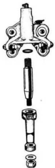
natural_image
Exploded view diagram of a mechanical assembly showing exploded and assembled parts (no text or labels)Fig.11.28. Exploded view of the steering idler assembly (early type)

Fig.11.29. Setting dimension for the steering idler fulcrum pin
4 Unscrew the fulcrum pin from the housing to remove it and then take out the "O" ring which will be found at the bottom of the housing.
5 To reassemble, first fit a new "O" ring in the groove at the bottom of the pin housing.
6 Now screw the fulcrum pin into the housing until the top of the taper is 3/16" (4.5 mm) from the bottom face of the idler housing as illustrated in Fig.11.29.
7 Offer the idler lever to the taper of the fulcrum pin and lightly tap it into position to grip on the taper but make sure that it is kept square.
8 Fit the washer and the self locking nut and tighten down, but make certain whilst tightening, that the fulcrum pin does not turn.
34 Steering idler assembly - refitting
Refitting is the reverse of the removal procedure but be sure that the idler lever and the drop arm are in the straight ahead position before fitting the track rod end to the lever. Using a grease gun, lubricate the assembly with the recommended grease.

Fig.11.30, Steering arm · Mk 1 cars

Fig.11.31. Steering idler lever · Mk 1 cars

Fig.11.32. Steering drop arm - Mk 1 cars
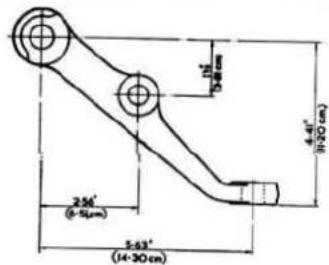

Fig.11.33. Steering arm - later type

Fig.11.34. Steering idler lever - later type

Fig.11.35. Steering drop arm - later type
35 Tie rod lever, left hand and right hand - removal and refitting
1 Raise the car to remove the appropriate front wheel. Support the car on a firmly based axle stand.
2 Take off the self locking nut and the plain washer securing the tie rod to the tie rod lever.
3 Support one side of the lever and then strike the other side several smart blows with a hammer to separate the tie rod ball pin from the taper of the lever.
4 Unscrew the self locking nut securing the stub axle shaft and the tie rod lever to the stub axle carrier.
5 Break the locking wire to the bolt attaching the end of the lever to the stub axle carrier and remove the bolt and the lever.
6 Refitting is the reverse of the removal procedure. Use soft iron locking wire to secure the wired bolt.
36 Tie-rod - removal and refitting
1 Place the car over a pit or raise the front of the car for access to the tie rod. Make sure that the car is well supported before working underneath it.
2 Take off the self locking nuts and the plain washers which secure the tie rod on the tie rod lever and the track rod end.
3 Support one side of the tie rod lever and then strike the other side several sharp blows with a hammer to break the taper joint. Repeat at the track rod end and remove the tie rod.
4 The tie rod ball joints cannot be dismantled so if they are worn a new assembly must be fitted.
5 Refitting is the reverse of the above procedure.
37 Track rod - removal
1 Remove the self locking nuts and the plain washers from the inner ball joint of each tie rod.
2 Support one side of the track rod end and strike the other side several smart blows with a hammer to separate the ball joint.
3 Remove the self locking nuts and the plain washers securing the track rod ends to the drop arm and the idler lever and separate the track rod ends in the manner already described.
4 Remove the track rod.
38 Track rod - dismantling and reassembling
1 Slacken the clamp at each end of the centre tube and unscrew the track rod ends noting that one has a left hand and the other a right hand thread. Note the number of turns required to separate each end so that they can be reassembled in approximately the same position.
2 If there is wear in the rubber/steel bonded bush at the track rod end, the assembly will have to be replaced.
3 Reassemble by screwing in the track rod ends to the tube the same number of turns as when removed (the final setting of the track rod length must be carried out after refitting to the car and as this requires special wheel alignment equipment it is a job which will have to be left to your Jaguar agent or any well equipped garage). For the time being, tighten down on the clamp bolts. The car will be driveable with care, with the track rod roughly adjusted in this manner but some wander in the steering must be anticipated and some scuffing and uneven wear of the tyres if driven for long distances.
39 Track rod - refitting
1 Refitting is the reverse of the removal procedure but it is essential that the steering drop arm and the idler lever are turned to the straight ahead position before fitting the track rod. Also the pins should be tapped into the drop arm and idler lever to prevent them turning when tightening the nuts. If those precautions are not observed, undue torsional loading of the rubber bushes will result and will give a tendency to steering wander and premature failure of the bushes.
40 Lock stop adjustment (standard steering)
1 Fig.11.29 shows the position of the lock stop bolts. The bolts which are screwed into the idler bracket and retained by locknuts, are set at the factory to allow 38° travel of the drop arm and the idler lever each side of the straight ahead position.
2 Adjustment is not normally necessary but if the setting of the bolts is upset for any reason, adjust their position as follows.
3 Slacken the locknuts and screw in the bolts as far as possible.
4 Turn the steering until it is at the end of its travel on that particular lock. Now screw out the bolt until the head contacts the idler lever and then centre the steering. Unscrew the bolt a further two turns and tighten down on the locknut.
5 Repeat the operations at paragraph 4 for the other lock.
41 Accidental damage to standard steering components
The dimensioned drawings at Figs. 11.30, 31 and 32 in respect of Mk 1 cars and at Figs. 11.33, 34 and 35 in respect of later models of cars fitted with standard steering, are provided to enable you to access the dimensional serviceability of steering components following damage to your car. Check also for fractures and deterioration. It must be noted that for Mk 1 models, the 5 7/8" (14.92 mm) dimension of the steering idler and the drop arm is reduced to 5½" (13.97 mm) with effect from the following chassis numbers:-
| RH Drive | LH Drive | |
| 2.4 litre | 914564 | 943496 |
| 3.4 litre | 976917 | 991866 |
42 Power assisted steering - general description
Power assisted steering is supplied as an optional extra for 3.4, 3.8 litre and 340 models only. Early cars were fitted with the Burman recirculating ball worm and nut type of steering box but this was replaced by the Adwest steering box which operates on the "hour glass" cam and roller principle. Apart from this, both systems have a similar layout and use the same type of pump.
The layout of the power assisted steering system (Burman box depicted) is given in Fig.11.36, it consists of an oil reservoir, an eccentric rotor type pump which is driven off the rear of the dynamo shaft a hydraulically assisted steering box. These items are connected by flexible hoses as follows:-
a) Reservoir to inlet side of the pump.
b) Outlet side of the pump to the inlet pipe connection attached to the steering box.
c) Outlet at the top of the steering box to the reservoir.
The pump supplies a continuous flow of oil through the system whilst the engine is running and the steering is in the straight ahead position. As soon as the steering column is rotated a valve is opened to allow oil to enter the appropriate pressure chamber.
A section view of the Burman type steering box is given in Fig.11.37. Hydraulic assistance is applied to a piston which forms part of the nut (G), the piston works within a cast iron cylinder and hydraulic pressure is admitted to one side or the other of it depending on which steering lock is applied. Admission of oil to the appropriate pressure chamber is controlled by a selector valve (M) which is mounted within the hollow rear end of the wormshaft (P) and to which the lower steering column is attached in the same manner as for standard steering. Rotary movement of the valve relative to the wormshaft opens and closes ports in the wormshaft and this directs oil to the side of the piston for the steering lock required.
A sectional view of the Adwest steering box is given in Fig.11.38. A hydraulic control valve, which is connected to the lower steering column in the same manner as the standard steering box, is embodied in the input shaft of the "hour glass" cam. The hydraulic assistance is supplied by a servo piston from which a rack projects, the teeth of which mesh with a sector of a spur gear which is machined on projection from the sector shaft. The track of the "hour glass" cam is machined with a varying helix so that the pitch is non-constant. A roller carried in the sector shaft meshes with this track and this is responsible for provision of the variable steering ratio.
Operation of the control valve is shown in Figs.11.39 and 11.40. This is a rotary type valve made up in two parts. The valve rotor, which is also the input shaft to the steering gear, has six grooves machined in it and these lie between six grooves in the valve sleeve when no load is applied to the steering wheel, the rotor being centred in the sleeve by the torsion bar. When the steering wheel is turned, effort is transmitted to the rotor which, in turn, transmits the effort to the hour glass cam by means of the torsion bar. The torsion bar is designed to twist under this effort thus allowing the rotor to rotate within the sleeve. The relative movement of the grooves in the rotor to the grooves in the sleeve causes a build up of hydraulic pressure on one side or the other of the servo piston, to assist turning the steering.

natural_image
Technical line drawing of a mechanical assembly with hoses and components (no text or labels)Fig.11.36. Layout of power assisted steering system

FIG.11.37. SECTIONED VIEW OF THE BURMAN POWER ASSISTED STEERING BOX
A Rocker shaft plunger springs
B Rocker shaft plunger
C Rocker shaft cover plate
D Thrust pad
E Bleed plug
F Rocker shaft
G Main nut
H Sealing sleeve
I Piston rings
J Roller race
K Interlock ball
L Twin lip oil seal
M Selector valve
N Bottom end plate
O Re-circulating balls
P Worm shaft or inner
column
Q Valve spring and plunger
R Top end plate
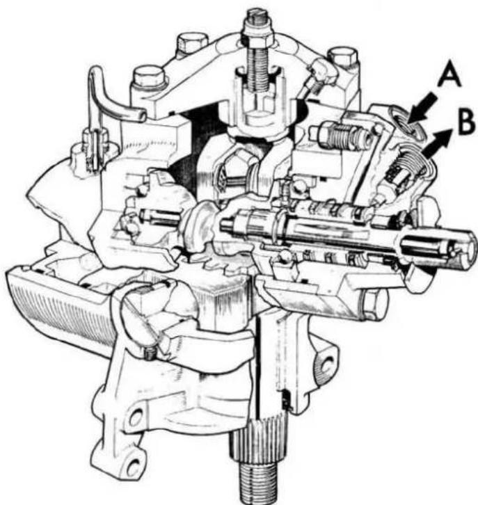
Fig.11.38. Sectioned view of the Adwest power assisted steering box. 'A' high pressure and 'B' low pressure connections
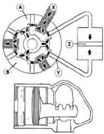

FIG.11.39. OPERATING DIAGRAM OF THE ROTOR VALVE (STRAIGHT AHEAD)
A Rotor
B Sleeve
X Pump pressure
Y Reservoir
pressure
Z Equilibrium
FIG.11.40. OPERATING DIAGRAM OF THE ROTOR VALVE (STEERING TURNED)
A Rotor
B Sleeve
X Pump pressure
Y Reservoir pressure
Z Pressure displace-
ment

43 Steering box, power assisted steering - removal
1 Place the car over a pit or on a ramp. If neither of those facilities are available, raise the front of the car to give access to the steering box but make sure that the car is well supported before doing any work underneath it.
2 Disconnect the high and low pressure unions from the box and hold a container beneath them to catch the oil which will escape. Blank off the pipes and the unions at the box to prevent the ingress of dirt.
3 Now refer to Section 20 and carry on in the manner described for removal of the standard type box.
44 Steering box, Burman, power assisted - dismantling
Always make sure that there is good reason for dismantling this steering box. Parts may not be available easily - it may be more efficient to purchase another steering box complete. Always check part availability.
1 An exploded view of the Burman type steering box is given at Fig.11.41 to which reference should be made during the following operations.
2 Remove the tab washer and nut securing the drop arm (34). Withdraw the drop arm from the rocker shaft.
3 Hold the steering box in a padded vice by the mounting boss. Place a container beneath the box to catch the oil which will escape as dismantling proceeds.
4 Remove the feed pipe assembly from the lower end cover and the rocker shaft cover.
5 Remove the rocker shaft cover to the steering box. Remove the set screw and recover the "O" ring.
6 Push up on the rocker shaft and remove the cover.
7 Take out the plunger (40) and the coil spring (41) and collect the thrust pad (39) from the counterbore in the cover.
8 Allow the oil to drain from the box into the container.
9 Remove the bottom cover (11) and take off the cover and the outer ball race.
10 Take off the top cover.
11 Lift up on the rocker shaft to disengage the ball on the nut assembly from the socket in the rocker arm and then withdraw the worm and nut assembly.
12 Lift out the rocker shaft.
13 Remove the end cover (29).
14 Take out the wormshaft and the main nut. Unscrew the nut from the wormshaft and collect the forty-four recirculating balls. Note that twenty-two of the balls are black in colour, these are smaller than the others by 0.007" (0.017 mm). It is essential that they are assembled alternatively with the larger one on reassembly of the box.
15 Take off the spring circlip and the sealing sleeve from the lower end of the worm.
16 Remove the circlip and the washer (28) and (27) from the upper end cover roller race assembly, and collect the twenty-four loose rollers.
17 Tap the cover against a block of wood to remove the race (25) followed by the packing piece, the "O" ring and the seal. If the race cannot be dislodged by tapping against the wooden block, immerse the end cover in boiling water for a few minutes and try again.
18 Remove the piston rings from the main nut assembly by lifting out one end and then working them round with the fingers. Do not stretch them too far as they are very brittle and are easily broken.
19 Remove the internal circlip, washer and sealing sleeve from the nut.
45 Steering box, Burman, power assisted - reassembly
Owing to the high working pressure of this unit (800-850 psi) we always replace all "O" rings and seals with new items on reassembly of the steering box.
1 Press the lower inner ball race into the bottom end of the box.
2 Fit the lower sealing sleeve inside the inner ball race and check for freedom of rotation.
3 Fit the lower sealing sleeve and the spring circlip onto the lower end of the valve assembly.
4 Fit the sealing sleeve over the tube pressed onto the worm and check for freedom of rotation.
5 Fit the top cover sealing sleeve onto the worm and check for freedom of rotation.
6 Assemble the sealing sleeve, the retaining washer and the circlip in the main nut.
7 Fit the piston rings to their grooves in the main nut.
8 Assemble the forty-four balls in the main nut making sure that the black and the bright balls are assembled alternatively. Now screw the worm and valve assembly into the nut taking care that none of the balls are dislodged from the nut. It will assist in keeping the balls in place if they, and the nut, are coated with light grease.
9 Press the oil seal into the recess in the end cover with the spring showing towards the inside of the box.
10 Fit the "O" ring and the sealing sleeve to the top end cover and then push in the roller race. Coat the race with light grease and then insert the twenty-four rollers. Secure with the washer and circlip.
11 Turn the piston rings so that the slots are opposed at 180^ and then compress them with a small ring clamp of a size which will fit into the recess in the end of the box. Carefully insert the
1 Steering box
2 Stud
3 Stud
4 O'ring
5 Dowel
6 Stud
7 'O'ring
8 Inner adjustable ball
race
9 Outer adjustable ball
race
10 Balls
11 Bottom end plate
12 Shim
13 Main nut
14 Piston ring
15 Balls (small)
16 Balls (large)
17 Sleeve
18 Washer
19 Circlip
20 Sleeve
21 Sleeve
22 Inner column assembly
23 Packing piece
24 'O'ring
25 Roller race
26 Rollers
27 Washer
28 Circlip
29 Top end plate
30 Seal
31 'O'ring
32 Rocker shaft
33 'O'ring
34 Drop arm
35 Nut
36 Washer
37 'O' ring
38 Cover plate
39 Thrust pad
40 Plunge
41 Spring
42 Bolt
43 Washer
44 'O' ring
45 Feed pipe
46 Connection for feed
pipe
47 Copper washer
48 Banjo bolt
49 Copper washer
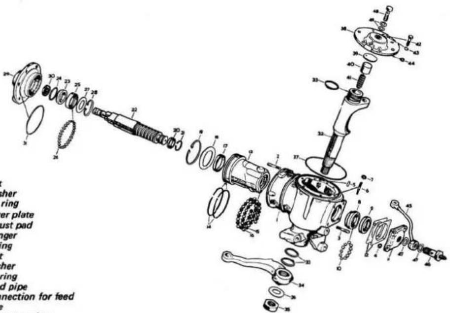
FIG.11.41. THE BURMAN POWER ASSISTED STEERING BOX
main nut into the box to assemble together with the rocker shaft. It will be necessary to turn the rocker shaft onto the far lock and to lift the rocker arm so that the ball on the nut will fit into the socket on the rocker arm.
12 Now coat the lower ball race with light grease and fit the eleven balls. Fit the outer ball race followed by the end plate with shims between the plate and the box so that the worm assembly just rotates freely without end float with the end plate tightened down. Now remove a 0.0025" (0.063 mm) shim to obtain the correct axial preload on the worm assembly.
13 Cover the serrations or: the valve with tape to prevent damage to the "O" ring when sliding it onto the spigot. Fit the "O" ring and the end cover with the oil outlet facing downwards for right hand drive, and facing upwards for left hand drive, cars. Remove the protective tape and tighten down evenly on the cover.
14 The end float of the rocker shaft must be checked, and adjusted as may be necessary, when refitting the top cover. The design of the box provides for a certain amount of end movement of the rocker shaft when on full lock and, as the shaft rises and falls slightly in travelling from lock to lock, adjustment for end float should be carried out at the highest point of the rocker arm travel.
15 Assemble the original thrust pad (39) and plunger (40), less spring, into the top cover and fit the top cover to the box but do not fit the "O" rings at this stage. Fit the cover securing bolts and tighten down evenly.
16 Rotate the input shaft by hand to check for tightness as the rocker passes over the highest point on each lock. If no tightness is felt, take off the top cover and replace the thrust pad by one 0.005" thicker (pads are available ranging in thickness from 0.155" to 0.185" in steps of 0.005"). Carry on checking and fitting thicker pads until restriction to movement is felt and then remove the padand fit one 0.005" thinner.
17 Assemble the "O" rings to the top cover face and to the top of the rocker shaft checking fit on the latter within the top cover bush. Insert the spring and the plunger in the rocker shaft, fit the thrust pad followed by the top cover. Fit the bolts to the cover and tighten down evenly or the top bush may be damaged.
18 Fit the drop arm making sure that the splines mate correctly and that the lines on the arm and on the rocker shaft coincide. 19 Fit the pipe between the bottom cover and the rocker shaft cover and use new copper washers on each side of the banjo connections.
46 Steering box, Adwest, power assisted - dismantling
Always make sure that there is good reason for dismantling this steering box. Parts may not be available easily it may be more efficient to purchase another steering box complete. Always check the part availability.
1 An exploded view of the Adwest steering box is given in Fig.11.42 to which reference should be made during the following operations.
2 Remove the nut (34) which secures the drop arm (33) to the sector shaft (24).
3 Mark the location of the drop arm in relation to the shaft for reassembly purposes and then, withdraw the drop arm from the splines of the shaft.
4 Remove the plug you fitted to the inlet orifice when disconnecting the pipe, invert the box and allow the oil to drain out.
5 Set the input shaft to the straight ahead position. Slacken the screw (22) and remove the rack adjusting plug with the seal (21) and the thrust pad (23).
6 Remove the top cover (25), and the sector shaft and worm follower assembly (24) from the box by tapping on the bottom of the shaft with a hide faced hammer (Fig.11.43).
7 Separate the top cover from the sector shaft assembly by undoing the locknut and then screwing off the cover.
8 Remove the circlip and take the seals and washers (items 29,30,31 and 32) out of the box.
9 Remove the alignment washer (11) and tap the valve housing (7) with a hide faced hammer to remove it. Collect the shims (12) which are located between the housing and the bearing outer race.
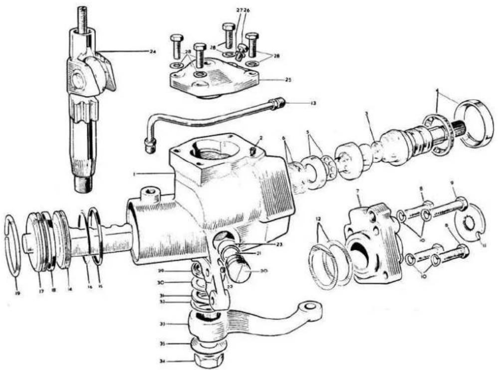
FIG.11.42. THE ADWEST POWER ASSISTED STEERING BOX
| 1 | Steering box | 11 Centralising washer | 21 Seal | 29 Seal |
| 2 | Screw | 12 Shims | 22 Screw | 30 Washer |
| 3 | Valve and worm | 13 Feed pipe assembly | 23 Thrust pad | 31 Seal |
| 4 | Ball bearing | 14 Piston and rack | 24 Sector shaft | 32 Circlip |
| 5 | Ball bearing | 15 Teflon sealing rings | 24 Sector shaft and worm | 33 Drop arm |
| 6 | Shims | 16 'O' rings | follower | 34 Nut |
| 7 | Valve housing | 17 Cylinder cover | 25 Top cover | 35 Tab washer |
| 8 | Bolt | 18 Seal | 26 Bleed screw | |
| 9 | Bolt | 19 Clip | 27 Washer | |
| 10 | Washer | 20 Plug | 28 Screw and lock washer |
10 Remove the valve and worm assembly (3) complete with the bearing (4) (Fig.11.44). If the bearing is to be replaced, withdraw the outer race. It is essential that none of the shims behind the outer race are mislaid.
11 DO NOT remove the trim screw shown in Fig.11.45 from the worm and valve assembly.
12 Remove the cylinder cover retaining clip (19) by forcing one end out of its groove using a short 3/16" (4.5 mm) steel punch. The clip can be eased clear with a screwdriver (Fig.11.46).
13 Remove the cylinder cover (17) complete with its seal by pulling on the centre boss.
14 Screw a long 12 inch UNC bolt into the tapped hole in the centre of the piston and rack (14) and withdraw the assembly through the open end of the cylinder (Fig.11.47).
47 Steering box, Adwest, power assisted - examination
1 Sector shaft assembly: Check for preload on the thrust bearing which should be free to rotate but should be slightly stiff with no side play. Examine the three sector teeth for signs of excessive wear. Look at the bearing areas on the top and bottom
of the shaft and make sure that wear is not excessive. Examine the seal area at the bottom of the shaft for wear, damage or grooving. Any fault found in the sector shaft assembly will entail replacement of the complete assembly.
2 Cover assembly: Examine the sector shaft bush for wear which, if excessive, will mean replacement of the cover. Discard the cover sealing ring.
3 Housing assembly: Examine the sector shaft bush for wear and the cylinder bore for damage, wear or scoring, any of these faults will entail replacement of the housing. Discard the sector shaft seal. Check the condition of the pipe seats in the housing and cover assemblies. If the seats are damaged in any way they can be replaced by tapping a suitable thread in the internal bore of the seat and then fitting a screw with an attached nut and plain washer; tighten the nut down against the housing case and withdraw the seat. Fit the new seal by inserting in the housing and tapping it home square with a soft punch.
4 Valve and worm assembly: Check the three teflon rings on the sleeve for damage, they should be a loose fit in their grooves and should be free from cuts, scratches and other blemishes. Examine the valve and worm ball bearing tracks for wear or
damage. Check that there is no relative movement at the trim pin between the valve sleeve and the worm. Check for wear in the torsion bar assembly pins by ensuring there is no free movement between the input shaft and the worm. Look for damage or wear at the needle bearing area towards the outer end of the shaft and look also, for wear in the area of the seal. Any faults other than in the teflon rings will entail replacement of the valve and worm assembly.
5 Piston and rack: Discard the teflon piston ring and the rubber "O" ring beneath it. Examine the rack teeth for signs of wear and the back face of the rack for wear caused by the rack adjuster pad.
6 Valve housing: Examine the bore for signs of wear or damage particularly in the area where the teflon rings have been rubbing. Look for damage in the needle roller bearing. Discard the seal.

natural_image
Technical line drawing of a mechanical pump assembly with hands operating it (no text or symbols present)Fig.11.43. Removing the sector shaft worm follower assembly and the top cover
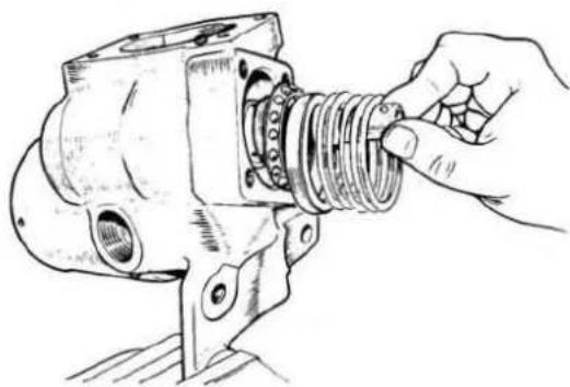
natural_image
Hand operating a mechanical component with a threaded shaft (no text or symbols visible)Fig.11.44. Removing the valve and worm assembly
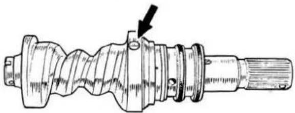
natural_image
Technical line drawing of a mechanical shaft assembly with no visible text or symbolsFig.11.45. Location of the trim screw
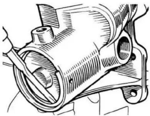
natural_image
Technical line drawing of a mechanical assembly with no visible text or symbolsFig.11.46. Removing the cylinder cover retaining clip
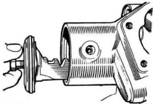
natural_image
Technical line drawing of a mechanical assembly with no visible text or symbolsFig.11.47. Using a bolt to withdraw the piston and rack assembly
48 Steering box, Adwest, power assisted - replacement of internal seals
1 If your examination of the teflon rings on the valve or worm shows that they have to be replaced, cut the old rings through with a sharp knife and remove from the groove.
2 Two special tools are used for fitting the rings, a Valve Seal Expander (Tool No. J 32) and a Valve Seal Compressor (Tool No. J 33), (Figs.11.48 and 11.44) you may be able to borrow these to do the job but if you are unable to do so, we suggest that you have the rings fitted in a workshop holding the necessary equipment as, without them, some difficulty may be experienced in expanding the rings to fit them without damage.
3 To fit a ring into a particular groove, slide the ring onto the expander and work it up to the large end. Now slide the expander over the sleeve and position the end cover over the groove to which the ring is to be fitted.
4 Push the ring over the end of the expander and into the groove.
5 It must be noted that the expander will not fit over the sleeve when rings are already fitted in the grooves so it may happen that you will have to discard serviceable rings in order to replace faulty ones.
6 Having expanded a ring and fitted it to the groove, it is now necessary to compress it into the groove and this is done by working the sleeve into the seal compressor or starting at the end of the tool having the shallow taper and finishing at the other end with the steep taper.
7 Check, when the compressor is withdrawn, that the ring is fitting snugly in the groove, is not damaged and is free to rotate.
49 Steering box, Adwest, power assisted - reassembling

natural_image
Technical line drawing of a mechanical component with threaded ends and textured fill (no text or symbols)Fig.11.48. Fitting a teflon ring using the valve seal expander

natural_image
Technical line drawing of a mechanical component with threaded end and flanged base (no text or symbols)Fig.11.49. The valve seal compressor
the box irrespective of their visual condition.
2 It is important that the worm is centred in the gear housing to ensure the correct relationship between the ratio curve, the preload peak and the central position of the steering gear. Look at the worm and you will see a figure etched on it and another figure will be found stamped on the valve housing (Fig.11.50) these figures indicate the amount, in thousandths of an inch, that the worm is short and that the box is deep over design limits. Add the two datum errors together to give the thickness of shims which must be placed in the bottom of the recess in the race housing. Shims are available in thicknesses of 0.002", 0.003" and 0.010".
3 Assemble the required pack of shims into the recess in the race housing.
4 Press the outer race of the small bearing into the recess on top of the shims.
5 Fit the ball bearing assembly and the large cage over the top of the worm.
6 Remove the large square sectioned "O" ring from the spigot of the valve housing assembly.
7 Fit the valve housing over the valve rotor taking care not to cause damage to the seal by the splines of the rotor.
8 Now check the input shaft for end float. Add shims between the valve housing and the gear housing to provide a 0.0015" (0.04 mm) gap, this should be measured whilst applying reasonable hand pressure to the valve housing (Fig.11.51).
9 Assemble the four bolts and washers to the valve housing and tighten down evenly.
10 Fit a new piston ring, and "O" ring beneath it, in the groove of the piston.
11 Screw a long 12 " UNC bolt into the tapped hole in the centre of the piston and press the piston into its bore with the teeth in the rack facing the sector shaft centre line. Take off the end plate and enter the piston until its end is 1.675" (42.5 mm) from the mouth of the cylinder (Fig.11.52). Refit the end plate. Align the piston in the bore so that the back face of the rack is hard up against the gear casing adjacent to the rack adjuster plug bore.
12 Assemble the top cover to the sector shaft assembly by screwing it on as far as it will go. Ensure that the square section "O" ring is fully home in its recess.
13 Protect the splined end of the sector shaft and assemble the shaft to the housing with the roller positioned towards the middle of the worm.
14 Work the sector to engage the teeth of the rack and move the input shaft to and fro to engage the worm and then push the sector shaft fully home.
15 Fit the four screws and washers and tighten down evenly to
secure the top cover at the same time making sure that the spigot is hard up against its recess in the casing aperture.
16 Assemble the thrust pad, the seal and the rack adjusting plug. In order to make sure that the pad remains in position it is advisable to fit these items with the box on its side with the adjuster plug uppermost. Fit the plug loosely and fit the locking screw finger tight.
17 Fit the seal to the cylinder cover, press the cover into the bore and then secure it with the retaining clip.
18 It is now necessary to adjust the sector shaft and the rack.
19 To adjust the sector shaft first make sure that the rack adjusting plug is slack, turn the input shaft from lock to lock using a torque wrench or just by "feel" noting the position at which the arm of the wrench turns through centre. Now note the torque felt one full turn from centre in either position.
20 Using a screwdriver, turn the adjusting bolt in a clockwise direction a little at a time at the same time turning the input shaft through the centre position until an increase of 4 lbf in over the torque previously noted is obtained at the centre position.
21 Lock the bolt with the locknut and recheck the adjustment by turning from lock to lock and if the adjustment is correct there will be an increase in torque of 4 lb f in over that of a turn from centre in either direction. It is important to avoid excessive preloading of the sector shaft assembly into the worm as this will result in possible poor return - efficiency.
22 The rack is adjusted in a very similar manner to adjustment of the sector shaft. First centre the gear as described in paragraph 19 and note the torque reading over the centre of the gear.
23 Now screw in the rack adjusting plug firmly to ensure proper seating and then slacken off by about a quarter of a turn.
24 Screw in the plug gradually and at the same time turn the input shaft through centre until an increase of 4 lb f in over the original reading is obtained.
25 Rotate the shaft from lock to lock and check that this adjustment has not produced an increase of torque in excess of 4 lb f in at any other point. If it has, reduce the torque at centre until that maximum limit is reached.
26 Finally lock the rack adjusting plug by means of the small socket screw.
27 Complete the assembly of the steering box by replacing the feed pipe and then fit the drop arm to the sector shaft with the location mark made at dismantling correctly aligned.
28 Fit the washer and the nut to secure the drop arm and tighten the nut to a torque of 130 lb f ft.

natural_image
Technical line drawing of a mechanical component with no visible text or symbolsFig.11.50. Location of depth marking on valve housing
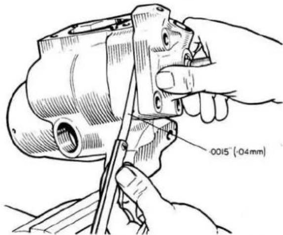
Fig.11.51. Checking the gap between the valve and gear housings

Fig.11.52. Assembly of the rack and piston
50 Steering box, power assisted - refitting
1 The steering box is refitted to the car in the manner described in Section 26 covering the standard box.
2 Ensure that the hydraulic connections are prefectly clean and then refit the high and low pressure hoses to the box.
3 Fill the reservoir to the full mark with the recommended grade of automatic transmission fluid and then bleed the system as described in Section 51.
51 Power assisted steering - bleeding the system
1 The system will only require bleeding when any hydraulic union has been disconnected or where, due to a leak, an excessive quantity of oil has been lost.
2 Make sure that the reservoir is full of oil.
3 Start the engine and allow it to idle, recheck the level of oil in the reservoir and top up as necessary.
4 Check all unions for leaks.
5 On early model cars not provided with a bleed screw in the top cover of the box, increase the engine speed to about 1000 rpm and turn the wheels in each direction five or six times.
6 On those cars fitted with a bleed screw (item 26 in Fig.11.42) slacken the screw whilst the engine is running and retighten securely when all air has been expelled. Turn the steering, with engine running, from lock to lock a few times and check for lumpiness
7 Finally, for both models, recheck for leaks and top up the reservoir.
52 Power steering pump - general
There are two types of oil pump which supply hydraulic pressure in the power assisted steering system. Early cars were fitted with a pump of the eccentric rotor type but this was superseded by a Hobourn-Eaton unit of the roller type on later cars. Both pumps incorporate a combined flow and relief valve and both are attached to the rear of the dynamo and are driven by a rubber coupling from the dynamo shaft. An exploded view of the early and later model pumps is given in Figs.11.53 and 11.54 respectively.

FIG.11.54. THE HOBOURN-EATON POWER STEERING PUMP
1 End plate
2 Oil seal
3 Orifice tube
4 Pump body
5 Flow control spring
6 Flow control valve
7 Valve seal
8 Valve cap
9 Sealing ring
10 Cam locking peg
11 Cam
12 Sealing ring
13 Roller carrier
14 Rollers
15 Drive shaft
15a Drive pin
16 Snap ring
17 Drive shaft bush
18 Thrust washer
19 Pump cover
20 Plug seal
21 Plug
22 Gasket
23 Adaptor
24 Fibre washer
25 Adaptor screw
26 Cover screw
27 Spring washer
28 Drive shaft bush
29 Dowel pin (2-off)
30 Spring washer
31 End plate screw

FIG.11.53. EXPLODED VIEW OF THE POWER STEERING PUMP (EARLY TYPE)
1 Oil pump body
assembly
2 Dowel
3 Sealing ring
4 Inlet pipe adaptor
53 Power steering pump - removal
1 Disconnect the hoses at the pump unions and secure the hose ends in a raised position to prevent the oil syphoning out or alternatively drain the oil into a container.
2 Blank off the hose union and plug the orifices of the pump to prevent the ingress of dirt.
3 Remove the nuts and lock washers securing the pump to the dynamo and remove the pump. If the flexible coupling comes away with the pump, withdraw it from the slot in the pump shaft.
54 Power steering pump, early type - dismantling
1 Thoroughly clean the exterior of the pump and take care that dirt does not enter the inlet or outlet orifices.
2 Refer to Fig.11.53.
3 Remove the two setscrews (5) holding the inlet adaptor (4) and take off the sealing ring (3).
4 Remove the five screws holding the cover assembly (13) to the body (1) and separate the cover from the body.
5 Take out the large and small sealing rings (6 and 7) from the grooves in the body housing.
6 Remove the thrust button (12) from the bearing hole in the cover.
7 Withdraw the drive shaft and the rotor assembly (9 and 8) and take care not to reverse the inner rotor in the outer rotor.
8 Remove the circlip (11) from the drive shaft.
9 Use a punch to drive out the bearing oil seal (19).
10 Remove the valve cap adaptor (17) and the seal (16) from the
14 Flow control valve
assembly
15 Return spring
16 '0' ring
17 Adaptor
18 Bolt and lock washer
19 Oil seal
20 Flow control valve
21 Spring
22 Relief valve
23 Circlip
24 Coupling assembly
25 Driving dog
pump cover. Take out the flow control valve spring (15) and the flow control valve assembly (20).
11 Remove the circlip (23) from the flow control valve and take out the relief valve (22) and the spring (21).
55 Power steering pump, Hobourn-Eaton type - dismantling
1 Thoroughly clean the exterior of the pump and make sure that dirt does not enter the inlet or outlet orifices. Maintain absolute cleanliness when dismantling the pump.
2 Refer to Fig.11.54.
3 Remove the adaptor screw (25) followed by the fibre washer (24) the adaptor (23) and the gasket (22).
4 Remove the six screws securing the cover (19) to the pump body (4).
5 Turn the pump so that the cover is uppermost and then lift off the cover.
6 Take out the sealing rings (9 and 12) from the grooves in the pump body.
7 Remove the thrust washer (18) from the bearing hole in the cover.
8 Take the snap ring (16) off the drive shaft (15) and withdraw the six rollers (14) and the roller carrier (13).
9 Remove the drive pin (15a) and withdraw the drive shaft from the body.
10 Remove the cam (11) from the cam locking peg (10).
11 Drift out the oil seal (2) but take care not to damage the drive shaft bush.
12 Unscrew the valve cap (8) and take out the valve seal (7), flow control valve (6) and the flow control valve spring (5).
56 Power steering pump, early type - examination and re-assembly
1 It is advisable to replace all seals and gaskets on reassembly of the pump.
2 Wash all parts and dry them on a clean non-fluffy rag.
3 Check the cover and body for signs of wear and replace if scored or worn.
4 Lubricate the seal (2) with transmission fluid and assemble it to the body with the lip pointing towards the rotor. It is advisable to use a press for this task with a 1.7/32" (30.95 mm) piece of bar as a piloting tool. Press the seal in to its fullest extent but do not squash it.
5 Assemble the shaft through the oil seal end of the body and gently rotate it whilst passing it through the seal.
6 Examine the drive and the driven rotors and if they are worn or scored replace them (the rotors are supplied in matched sets).
7 Place the rotors over the shaft in the pump body and check the clearance between them at all points. The rotors should be replaced if the clearance exceeds 0.006" (0.15 mm).
8 Place a straight edge across the pump body and, using feeler gauges, check the end clearance of the rotors in the pump body.
The end clearance should not exceed 0.0025" (0.06 mm), replace the pump body if this dimension is exceeded.
9 Now check the clearance between the driven rotor and the bushing in the pump body. Replace the body if the clearance exceeds 0.008" (0.20 mm).
10 Fit the drive pin in the slot of the shaft and drive rotor.
11 Carefully check that the relief valve is not sticking in the flow control valve, use a fine oil stone to remove any burrs as may be causing trouble.
12 Insert the relief valve spring, followed by the relief valve, in the flow control valve and fit the circlip to hold them in place.
13 Assemble the flow control valve and the spring in the pump cover. Fit the valve cap adaptor with a new seal and screw down securely.
14 Fit new "O" ring seals to the grooves in the body of the pump. Fit the pump body and the cover together and secure with the five screws tightened down evenly. Check that the shaft is not binding.
15 Fit a new seal at the inlet pipe adaptor and refit the adaptor.
57 Power steering pump, Hobourn-Eaton type - examination and reassembly
1 It is advisable to replace all seals and gaskets on reassembly of the pump.
2 Wash all parts and dry them on a non-fluffy cloth.
3 Check the pump body and the cover for wear and replace if the faces or bushes are scored or worn.
4 Fit a new oil seal in the same manner as described in paragraph 4 of Section 56.
5 Refit the cam locking peg. Examine the cam for wear and if it appears satisfactory refit it with the slot over the locking peg and make sure that it is seated correctly.
6 Make sure there are no sharp edges on the drive shaft as may damage the seal and then insert the shaft from the seal side of the body.
7 Fit the drive pin to the shaft, examine the roller carrier and if there are no signs of wear fit it into position as shown in Fig.11.55. Be sure that the correct face of the carrier slots are driving the rollers. Fit the snap ring to hold the carrier in position.
8 Examine the rollers, replace them if they are scored, damaged or if there is any degree of ovality. Fit them to the carrier if they appear satisfactory.
9 Place a straight edge across cam surface and, using feeler gauges, check the end float of the carrier and rollers in the pump body. The end float should not exceed 0.002" (0.051 mm) and if this dimension is exceeded the rollers and carrier must be replaced.
10 Make up a rig for checking the tension of the valve spring. A piece of bar, over which the spring will pass, held in a vice will be satisfactory to support the spring and all that is needed is weights to pass over the bar onto the spring. The tension of the spring should be between 8 - 9 lb (3,63 - 4.08 kg) when compressed to a length of 0.02" (20.8 mm).
11 Fit the spring to the body followed by the valve with the ball bearing end entering last. Check that the valve is not sticking.
12 Refit the cap with a new sealing ring and tighten to a torque of 30 - 35 lb f ft (4.15 - 4.84 kg f m).
13 Fit new sealing rings to the pump body joint face.
14 Fit the thrust washer to the cover and refit the pump cover to the body. Secure the cover and the body with the six screws and tighten down evenly to a torque of 18 lb f ft (2.49 kg f m). Check the drive shaft for freedom in rotation.
15 Fit a new rubber gasket to the adaptor on the cover and refit the adaptor bolt.
16 If the plug in the top of the cover has been removed, make sure that an air tight seal is obtained when it is replaced.

natural_image
Technical line drawing of a mechanical component with central hub and multiple bolt holes (no text or symbols)Fig.11.55. Assembly of the roller carrier
58 Power steering pump - refitting
1 Place the flexible coupling assembly in the slot in the dynamo shaft and align the slot in the pump driving shaft with the driving tongue on the flexible coupling.
2 Place the pump on its mounting studs and after a final check that the coupling drive is correctly aligned, push the pump home and secure with the nuts and spring washers.
3 Reconnect the inlet and outlet hose to the pump.
4 Bleed the system as described in Section 51.
59 Power steering oil reservoir · dismantling, examination and reassembling
1 Remove the pump inlet hose from beneath the reservoir and allow the oil to drain into a container.
2 The procedures which follow can be carried out with the reservoir installed in the car but if it is desired to remove the reservoir this can be done by first removing the other hydraulic pipe. Now undo the two pipe adaptors which hold the reservoir on the mounting bracket noting that the feed and return adaptors have different sized threads. Collect the "O" rings located between the adaptors and the bracket. Lift off the reservoir and collect the "O" rings between it and the bracket.
3 Thoroughly clean the exterior of the reservoir.
4 Remove the screw securing the cover and take off the "O" ring beneath it. Lift off the cover with its gasket.
5 Take out the filter (Purolator MFH.117) (HE.1307).
6 Clean out any residue which may have collected in the bottom of the reservoir.
7 Reassembly is the reverse of the above procedure. It is advisable to fit new gaskets and "O" rings at reassembly. The filter should be changed every 25,000 miles.
8 When replacing the cover, make sure that it is replaced flush with the reservoir body.
9 Finally refill the reservoir with automatic transmission fluid of the recommended type.
60 Power steering idler assembly - removal
The power steering idler assembly is removed from the car in the same manner as the idler assembly for standard steering as described in Section 32 except that, owing to the different configuration of the lock stop bolts for power steering (see Fig.11.57), one lock stop bolt acts as a securing bolt and must be removed.
61 Power steering idler assembly - dismantling and reassembly
The following procedures also cover the later type idler assembly fitted to cars equipped with standard steering.
1 An exploded view of the steering idler assembly is given in Fig.11.56.
2 Take off the self locking nut and plain washer which secure the lever to the shaft. Apply a suitable extractor to the lever and withdraw it from the shaft. However, there is no need to remove the lever unless it is required.
3 Prise out the dust cap from the top of the idler bracket.
4 Knock back the tab locking the nut at the top of the shaft and unscrew it from the idler shaft. Take out the tab washer and the "D" washer underneath it.
5 The shaft can now be withdrawn. Collect the abutment washer and its ring (located between the lever and the body of the assembly), the felt seal and its retaining ring.
6 Remove the upper and lower taper roller bearings.
7 Thoroughly cleanout the races and the idler housing.
8 Repack the housing and the bearing with the recommended greases.
9 Refit components to the housing in the reverse order in which they were removed. It is advisable to fit a new felt seal.
10 Tighten the nut at the top of the shaft to a torque of 5 lb f ft or, alternatively, tighten the nut until movement of the shaft feels restricted and then slacken the nut one flat. Lock the nut with a new tab washer and refit the dust cap.
62 Power steering idler assembly - refitting
The power steering idler assembly is refitted to the car in the same manner as that for standard steering as described in Section 34 except that, as the position of the lock stop has been upset, it will be necessary to adjust the lock stop, as described in Section 63.
63 Power steering - lock stop adjustment
The position of the lock stops fitted to models with power steering is shown in Fig.11.57. The lockstops are adjusted in the manner described in Section 40 except that the bolts are screwed out four turns from their contact position on full lock and not two turns as for standard steering.
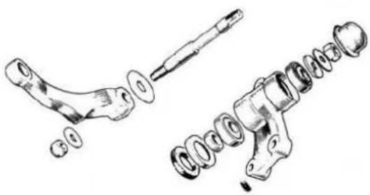
natural_image
Exploded view diagram of a mechanical assembly showing internal components and parts (no text or labels)Fig.11.56. Steering idler, power assisted steering
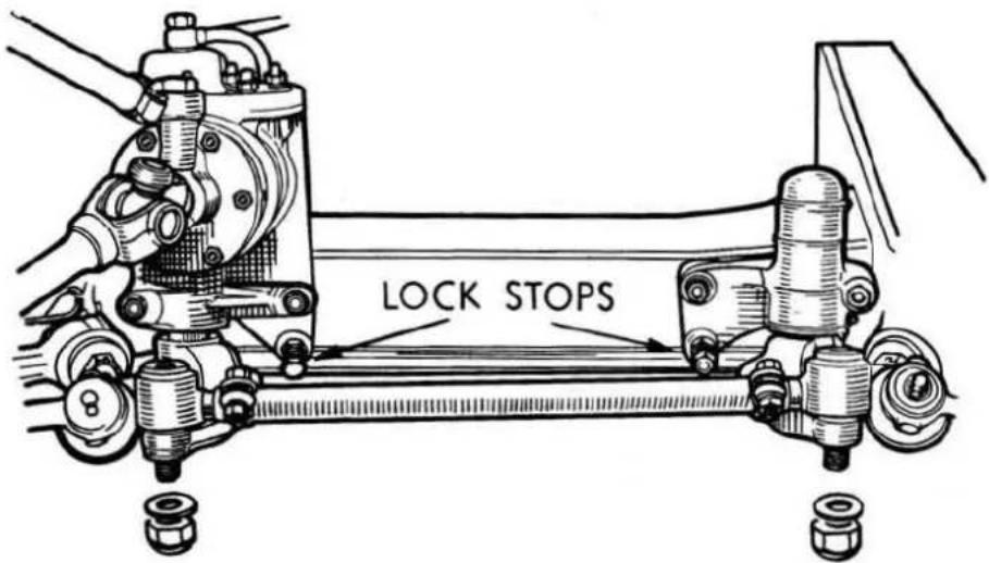
Fig.11.57. Location of lock stop bolts, power assisted steering
64 Power steering - adjustment and check of gear when installed in car
a) Sector shaft adjustment, Adwest steering box: Lost motion in the steering box will probably be due to wear between the hour glass cam and roller. To check, centralise the steering by positioning the cut-away on the centralising washer (item 11 in Fig.11.42) over the hole in the steering box and then insert a piece of 14'' (6.4 mm) rod to make sure that the position is correct. Disconnect the tie rod from the drop arm (see Section 20) and rock the drop arm to both sides of the centre line to feel for excessive backlash which, if present, may be rectified by slackening the locknut on the top of the box and then screwing down on the adjuster screw until only slight backlash is felt. Retighten the locknut and refit the tie rod and road test the car. If lost motion is still present, the box will have to be removed and overhauled.
b) Steering pulling to one side: First check tyre pressures and change tyres from one side to the other and if the pull changes direction the fault lies in the tyres. If the pull remains, check the steering linkage for wear and, if this is satisfactory, have the alignment of the front wheels checked. If there is still no improvement the fault must lie in the trimming of the valve in the steering box. To check, insert a 2,000 lb/sq in pressure gauge in the pressure line, start the engine and allow it to idle. Now turn the steering to the left and then to the right and check that the pressures recorded on moving to each side are equal. If the pressure rise is not balanced, the steering box will have to be removed from the car for replacement of the worm and valve assembly.
c) Checking the hydraulic system: Install a pressure gauge, which is fitted with a tap so that pressure to the steering box can be shut off, in the pressure line between the pump and the steering box. Check the fluid in the reservoir for correct level and freedom from froth. Make sure that the tap is open to the box and then start the engine and run at idle speed, now turn the steering to full lock and increase the effort until the pressure shown on the gauge ceases to increase. The pressure recorded should be between 950 and 1000 lb/sq in (65 to 70 kg/sq cm) and it should not increase with engine speed. If the pressure is below that figure but rises to it with increased engine speed then the trouble is probably due to, either a faulty control valve in the pump, or to internal leakage in the steering box. To find out where the fault lies, close the tap for a maximum of five seconds with the steering still at full lock, if the pressure rises to the correct figure the fault is in the steering box which will have to be removed and overhauled, if the pressure is still low the fault is in the pump.
65 Accidental damage to power steering components
The dimensional drawings at Figs.11.58 and 11.59 are provided to enable you to assess the dimensional serviceability of power steering components following accidental damage to your car. Always check for fractures and deterioration as well.
66 Front wheel alignment
The correct alignment for the front wheels is :-
Mk.1 models and 2.4 litre Mk.2 - parallel to 1/16" (1.59
All other models - parallel to 1/8" (3.2)
mm) toe-in
parallel to 1/8" (3.2
mm) toe-in
The alignment must be checked when the car is full of petrol, oil and water and is standing on a level surface with all tyre pressures correct. In addition, for those cars fitted with power steering, the steering must be centralised (see Section 64 paragraph (a)).
The adjustment is effected by loosening the clamps at each end of the track rod and then rotating the tube until the adjustment is correct.
Accurate alignment of the front wheels is essential otherwise the steering will be vague with wear on the tyres will be heavy and uneven. Accurate alignment requires the use of special equipment so this is a task which is best left to your Jaguar agent or another fully equipped garage.


natural_image
Simple line drawing of a mechanical linkage or lever (no text or symbols)Fig.11.58. Drop arm, power assisted steering
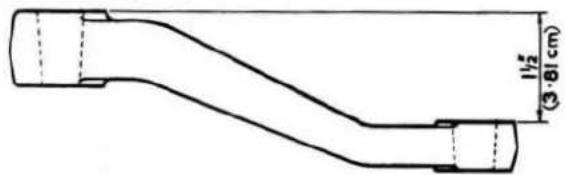

Fig.11.59. Power assisted steering idler lever
67 Fault diagnosis
| Symptom | Reason/s | Remedy |
| (Standard Steering) | ||
| STEERING FEELS VAGUE, CAR WANDERS AND FLOATS AT SPEED | ||
| General wear or damage | Tyre pressures unevenShock absorbers wornSteering gear ball joints badly wornSuspension geometry incorrectSteering mechanism free play excessiveFront suspension and rear suspension pick-up points out of alignment or badly wornFront suspension lacking grease | Check pressures and adjust as necessary.Test, and replace if worn.Fit new ball joints.Check and rectify.Adjust or overhaul steering mechanism.Normally caused by poor repair work after a serious accident. Extensive rebuilding necessary.Check condition and grease or replace worn parts and re-grease. |
| STIFF AND HEAVY STEERING | ||
| Lack of maintenance or accident damage | Tyre pressures too lowNo oil in steering boxNo grease in steering ball jointsFront wheel toe-in incorrectSuspension geometry incorrectSteering gear incorrectly adjusted too tightlySteering column badly misaligned | Check pressures and inflate tyres.Top up steering box.Replace.Check and reset toe-in.Check and rectify.Check and re-adjust steering gear.Determine cause and rectify (usually due to bad repair after severe accident damage and difficult to correct). |
| WHEEL WOBBLE AND VIBRATION | ||
| General wear or damage | Wheel nuts looseFront wheels and tyres out of balanceSteering ball joints badly wornHub bearings badly wornSteering gear free play excessive | Check and tighten as necessary.Balance wheels and tyres and add weights as necessary.Replace steering gear ball joints.Remove and fit new hub bearings.Adjust and overhaul steering gear. |
| (Power Steering) | ||
| IMPORTANT: Check that the fluid reservoir is filled to the correct level before investigating any steering fault. | ||
| Steering pulling to one side | Imbalanced front tyres. Damaged tyres. Incorrect tyre pressuresSteering gear out of trim | Balance front wheels. Replace tyres. Correct pressuresReplace worm and shaft if out of trim. |
| Steering feels different to 'left' and 'right', but does not actually pull | Incorrectly centred worm and valve. The worm and valve assembly will be on the wrong part of the ratio curve when driving straight ahead | Centralise. It may be necessary to re-align the steering wheel after operation. |
| Heavy steering when driving | Low tyre pressures. Tightness or stiffness in the steering column and/or steering and suspension jointsSteering gear adjusted too tightly | Inflate. Grease or replace.Re-adjust steering box as necessary. |
| Heavy steering when parking | Loose pump belt (accompanied by squealing).Insufficient pressure from pump due to restricted hoses or defective control valve.Insufficient pressure due to leaks in steering gear | Check belt and replace if necessary.Remove restriction or check control valve.Check for correct blow-off pressure. Confirm internal leaks by carrying out leak tests. If proved, remove gear and replace seals. |
| Steering effort too light | Worn torsion bar pins or torsion bar broken | Remove steering box; remove worm and valve assembly; check that valve rotor has no free play relative to valve sleeve. Replace worm and valve assembly as necessary. |
| Imbalance of steering effort varying irregularly | Worn or loose trim screwRotor sticking in valve sleeve | Replace worm and valve assembly.Remove steering box; remove worm and valve assembly. Hold worm in hand and rotate rotor to and fro feeling for sticking.Replace worm and valve assembly if necessary. |
Chapter 12 Bodywork and underframe
Contents
| General description | ... | ... | ... | ... | ... | ... | 1 |
| Maintenance - body and underframe | ... | ... | ... | ... | ... | ... | 2 |
| Maintenance - upholstery and carpets | ... | ... | ... | ... | 3 | ||
| Body repairs - minor | ... | ... | ... | ... | ... | ... | 4 |
| Body repairs - major | ... | ... | ... | ... | ... | ... | 5 |
| Wood trim panels - renovation | ... | ... | ... | ... | ... | ... | 6 |
| Maintenance - locks and hinges | ... | ... | ... | ... | 7 | ||
| Door rattles - tracing and rectification | ... | ... | ... | ... | 8 | ||
| Front doors and hinges - removal and refitting | ... | ... | ... | ... | 9 | ||
| Rear doors and hinges - removal and refitting | ... | ... | ... | ... | 10 | ||
| Front and rear door trim casings - removal and refitting | ... | ... | ... | ... | 11 | ||
| Front and rear door window frames and glass - removal and refitting | ... | ... | ... | ... | ... | ... | 12 |
| Front no draught ventilator - removal and refitting | ... | ... | ... | ... | ... | ... | 13 |
| Rear no draught ventilator - removal and refitting | ... | ... | ... | ... | ... | ... | 14 |
| Front and rear window winding mechanism - removal and refitting | ... | ... | ... | ... | ... | ... | 15 |
| Door locks Mk 1 cars - removal and refitting | ... | ... | ... | ... | 16 | ||
| Door locks Mk 2 and later cars - removal and refitting | ... | ... | ... | ... | 17 | ||
| Windscreen - removal and refitting | ... | ... | ... | ... | ... | ... | 18 |
| Rear window glass - removal and refitting | ... | ... | ... | 19 |
| Facia panels - removal and refitting | ... | ... | ... | 20 |
| Radiator grille - removal and refitting | ... | ... | ... | 21 |
| Bonnet lock - removal, refitting and adjustment | ... | ... | ... | 22 |
| Bonnet - removal and refitting | ... | ... | ... | 23 |
| Luggage compartment lid and hinges - removal and refitting | ... | ... | ... | 24 |
| Front bumper and over-riders - removal and refitting | ... | ... | ... | 25 |
| Rear bumper and over-riders - removal and refitting | ... | ... | ... | 26 |
| Petrol filler lid - removal and refitting | ... | ... | ... | 27 |
| Heater unit - removal and refitting | ... | ... | ... | 28 |
| Heater water control tap - removal and refitting | ... | ... | ... | 29 |
| Exhaust system - general | ... | ... | ... | 30 |
| Exhaust system - removal and refitting | ... | ... | ... | 31 |
| Wheels and tyres - general | ... | ... | ... | 32 |
| Tyre inflation pressures | ... | ... | ... | 33 |
| Wheel alignment and tyre wear | ... | ... | ... | 34 |
| Tyre replacement and wheel interchanging | ... | ... | ... | 35 |
| Wire spoke wheels - removal and refitting | ... | ... | ... | 36 |
| Wire spoke wheels - repair and adjustment | ... | ... | ... | 37 |
1 General description
The Jaguar range of cars covered by this manual are compact four/five seater saloons of unitary construction. That is to say, the body is made up of panels as illustrated in Fig.12.1 which are welded together to make up the well styled and attractive shape with which we are all familiar. The body is mounted on an underframe the parts of which are shown at Fig.12.2. All the items of the body and underframe shown in Figs.12.1 and 12.2 are catalogued as spares and so can be obtained for the repair in whole, or in part, of damaged components depending, of course, on the degree of damage to the vehicle as to whether or not
repair is a worthwhile proposition.
Modifications to styling since introduction of the Mk 1 model in 1955 have been of a comparatively minor nature only and are confined mainly to the introduction of cut-away rear wheel covers, new wrap round rear window, slimmer window pillars and a larger windscreen. The main interior difference has been the introduction of a red signed instrument panel from which, in later cars, the speedometer and revolution counter has been removed to a position directly in front of the driver.
The interior features two bucket seats at the front which are adjustable for height and reach and which are upholstered in leather. The rear seat squab and backrest, also upholstered in leather, are provided with a centre armrest.

natural_image
Exploded view diagram of a car showing internal components and structural details (no text or labels)Fig.12.1. The body panels

natural_image
Exploded view of mechanical components including cutouts, brackets, and parts (no text or symbols)Fig.12.2. The underframe components
2 Maintenance - body and underframe
1 The condition of the bodywork is of considerable importance as it is on the visual condition of this that the re-sale value of the car will mainly depend. It is much more difficult, and costly, to repair neglected bodywork than it is to renew mechanical assemblies. Attention to the hidden portions of the body such as the wheel arches and the underframe is as important, if not more so, than periodic cleaning and polishing of the paintwork.
2 At frequent intervals, especially during the winter months, remove the rear wheel covers, raise the car and thoroughly hose. Down underneath to remove all mud and road dirt from the wheel arches and projections on the underframe. Pay particular attention to the front part of the front wheel arches, the valance beneath the radiator, inside as well as the outside of the four jacking points, and do make sure that the rubber plugs are fitted at these points, the space between the petrol tank and the body and the wheel covers themselves. These, amongst others, are all places where mud will collect and cause corrosion especially if impregnated with salt.
3 The insides of the doors are fairly well protected but nevertheless take off the door panels at least once a year, to make sure that the drain holes are clear and that there is no corrosion.
4 Once a year, preferably in the summer, is advisable to have the underside of the body steam cleaned. This will remove all traces of dirt and oil so that the underside can be examined for rust, damaged pipes or electrical wiring.
5 The wheel arches should be given particular attention to ensure that the undersaling has not been damaged by stones thrown up from the wheels. If damage is found, clean down to the bare metal using a wire brush and then paint on a rust inhibitor or, if preferred, red lead and finally recover the area with underseal.
3 Maintenance - upholstery and carpets
1 Remove the carpets and thoroughly vacuum clean the interior of the car at frequent intervals at the same time checking that dampness, to the extent of causing corrosion of the floor, is not present.
2 Use the vacuum cleaner on the seats and backrests to remove grit from the partitions as may cause chafing and breakage of the stitching.
3 Vacuum clean the carpets and if they are dirty they can be cleaned with one of the many proprietary cleaners which are now on the market.
4 It is suggested that you use saddle soap on the leather upholstery. This will not only clean the leather but will also "feed" it and help to keep it supple.
4 Body repair - minor
1 The rectification of major body damage should be left to a body repair specialist having the necessary equipment and "know-how" to restore the car to the condition it deserves. However, there is no reason why you cannot successfully beat out, repair and respray minor damage yourself.
2 The most common defect arising in the bodywork is chipping of the paint by stones thrown up from other cars. These blemishes can be repaired by first treating the chip with a rust inhibitor and then applying "touch-up" paint of the matching colour of your car. Allow the paint to dry. You will probably find that it has shrunk and left a depression in which case apply more paint, but not too much, and again allow to dry. Carry on applying paint until it stands slightly proud of the chip and now leave it for a couple of days to harden off. Now obtain a handy sized block of wood for rubbing down, cover the block evenly with cloth (flannel is ideal) and impregnate the cloth with metal polish. Rub down on the paint using a motion to conform to the particular shape of the panel, do not worry about damaging the
surrounding area of old paint finish as this will be much harder than the new surface which you have applied and which will quickly rub down to give a perfect match.
3 Larger areas of damage will need a different approach to the above.
4 Dents can be knocked out from underneath but never use a metal hammer as this will bruise and distort the metal. Use a mallet or hide faced hammer when knocking out a dent and at the same time support the metal with a sandbag or wooden block; beat out the dent as best you can but under no circumstances beat it out to the extent of standing proud of the surrounding metal because in this case the raised portion of metal will have to be cut out in order to get a flat finish.
5 Having beaten out the dent, clean down to the bare metal and, then, if there is no rust present, apply a filler such as Holts "Cataloy" and smooth it over the area as evenly as possible. Do not mix the filler too thinly or it will tend to run on the other hand a stiff mix will be difficult to apply and will harden off as you are working.
6 Allow time for the filler to harden (usually about 30 minutes) and then follow the instructions for rubbing down the type of filler you used. Fillers of the Holts "Catalogy", Isopon etc can first be roughly filed to shape and then carry on with glass paper followed by a medium and fine grade wet and dry paper to feather the patch in to the surrounding area.
7 When doing any rubbing down, use a block of wood padded with cloth to support the rubbing down paper. If you use your hand or fingers they will follow any irregularities and you will never finish up with a flat surface.
8 Protect surfaces as necessary from paint using masking tape, newspaper held on by tape etc. or even use grease for small areas but do not allow any oil or grease to come into contact with the area you are going to paint. Now spray on an undercoat, allow it to harden and look for blemishes in your filling work, it is surprising how defects will now show up. Use more filler and rub down again as necessary.
9 When satisfied with the undercoat, rub down with a fine grade wet and dry paper and then, when the surface is clean and dry, apply the finishing coats of the matching colour of your car. The number of coats applied is a matter of choice but do not try to finish the job in one application, several very light coats are better than a couple of heavy applications which in any event will most likely result in "runs". Rub down between each coat and then when the final coat has had time to harden, polish the whole area with a fine cutting paste.
10 The final treatment for the repair of holes or cuts is the same as the foregoing but first a base has to be provided to hold the filler. This can be done by welding (and this may be the only answer if a large hole, the result of body rot due to rust, is to be repaired) or by using fibre glass as a patching agent.
11 Assuming you are going to use fibre glass to repair a hole resulting from rust, first cut away all other corroded metal and then clean down to the bare metal for a distance of about 1½" all round the hole and apply a rust inhibitor.
12 Knock down the edge of the hole so that it is below the surface. Apply the fibre glass patch in accordance with the instructions for the type being used and then, when it is dry and hard, treat as for a dent as already described in this Section.
13 Beat out a cut but leave the edges below the surface. Clean down to the bare metal and then carry on to patch and fill as described previously.
5 Body repairs - major
Repairs to rectify extensive damage affecting the main members of the underframe must be carried out so that when the repair is completed the main mounting points for the engine, front and rear suspension etc., are in correct relation to each other. Checking of those features requires a jig and specialised knowledge of the car and its construction. We strongly recommend that, in the event of major damage to your car, you ensure that your repairer, if not a Jaguar agent, has the align-
ment of the underframe checked in both the vertical and horizontal plane by a Jaguar specialist.
6 Wood trim panels - renovation
The wooden screen rail capping and the door trim strips are prone to damage by the varnish lifting due to heat of the sun. We have found that a good method of renovation is to remove them as described later in this Chapter and then scrape off all the old varnish and rub down to the bare wood with a fine garnet paper. Now apply a walnut polyurethane wood filler and when this is dry, rub it down to a fine finish. Finally apply two coats of either a gloss or matt finish, depending on your choice, polyurethane varnish, rubbing down after each coat. You will find that this will give a durable surface which will last for a considerable time.
7 Maintenance - locks and hinges
Once every 6,000 miles (10,000 km) the door, bonnet and boot hinges should be oiled with a few drops of engine oil from an oil can. The door striker plates should be given a smear of grease to reduce wear and ensure free movement.
8 Door rattles - tracing and rectification
1 The most common cause of door rattles is a misaligned, loose or worn striker plate.
2 To remove the striker plate, take out the three securing screws and lift the plate away from the door pillar.
3 Fit the new striker plate and assemble the three screws loosely to the adjustable tapping plate in the pillar.
4 Positioning is a matter of trial and error until the door can be closed easily without rattling and when no lifting or dropping of the door is apparent, when opening or closing.
5 Other causes of door rattles may be:-
a) Loose door handles, window winder handles or door hinges.
b) Loose worn or misaligned door lock components.
c) Loose or worn remote control mechanism.
d) A combination of the above.
9 Front doors and hinges - removal and refitting
1 Obtain the services of an assistant to take the weight of the door when the securing bolts are removed.
2 Take out the split pin and the clevis pin on the door check strap bracket.
3 Mark the positions of the hinges on the door for ease of alignment on refinement.
4 Slacken the six bolts securing the hinges to the door and then have your assistant to take the weight of the door.
5 Remove the six bolts and then lift off the door.
6 Take off the scuttle side casing by removing the three screws.
7 Take out the two screws and remove the aperture cover plate.
8 Remove the door courtesy light switch from the bottom hinge recess and disconnect the cable at the rear of the switch.
9 Remove the hinges (Fig.12.3) by taking out the cross headed screws and the bolts inside the hinge recess.
10 Refitting is the reverse of the removal procedure but adjust the hinges to your marks or until the door fits correctly and then check adjustment of the striker plate as described in Section 8.
10 Rear doors and hinges - removal and refitting
1 Obtain the services of an assistant to take the weight of the door when the securing bolts are removed.
2 Remove the split pin and the clevis pin on the door check
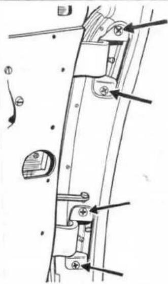
natural_image
Technical diagram of a mechanical assembly with mounting holes and adjustment knobs (no text or labels)Fig.12.3. The screws securing the front door hinges
strap bracket.
3 Refer to Section 11 and take off the door trim casing.
4 Mark the position of the hinges on the door.
5 Slacken the three bolts securing the bottom hinge and the four cross headed screws securing the top hinge and then have your assistant to take the weight of the door.
6 Remove the bolts and screws from the hinges and lift off the door.
7 Take out the two cross headed screws on the rear door side of each hinge (Fig.12.4) and the cross headed screw to each hinge from the front door side of the door pillar (Fig.12.5) and then take off the hinge.
8 Refitting is the reverse of the above removal sequence but adjust the hinges to your marks or until the door fits correctly and then check the position of the striker plate as described in Section 8.

Fig.12.4. The screws securing the rear door hinges

natural_image
Diagram of a mechanical device attached to a textured surface, with arrows indicating force or movement (no text or symbols present)Fig.12.5. Showing the two screws at the front of the centre pillar which secure the rear door hinges
11 Front and rear door trim casings - removal and refitting
1 Take out the four screws which attach the wood capping to the waist rail (Fig.12.6). Lift off the capping and now prise up the tacks securing the felt to the waist rail.
2 Take out the three screws shown in Fig.12.7 which hold the waist rail to the door frame and remove the waist rail.
3 The door casing covering is attached to the door frame at the bottom of the window aperture by adhesive so pull it away carefully. Four screws holding the millboard casing to the door frame will now be uncovered (Fig.12.8) and these must be removed.
4 Refer to Fig.12.9. Press in the spring loaded cap on both the door and window handles. A small retaining pin will now be uncovered and this should be pressed out to remove the handles.
5 The door casing is now held to the door by clips, twenty-one in the case of the front door and eighteen for the rear. Prise the casing off the door by inserting a thin bladed screwdriver and working round evenly.
6 Refitment of the trim casings is the reverse of the above. Take care that your screwdriver does not slip when refitting the waist rail capping and damage it.
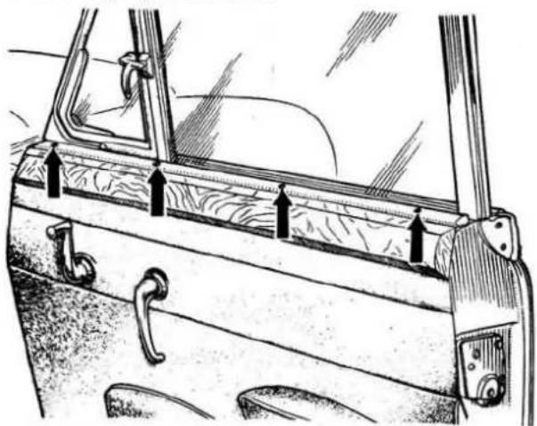
natural_image
Technical line drawing of a mechanical component with mounting holes and internal channels (no text or symbols)Fig.12.6. Showing the screws holding the wood capping to the waist rail

natural_image
Technical line drawing of a mechanical assembly with wooden components and curved fittings (no text or symbols)Fig.12.7. Showing the three screws securing the waist rail to the door frame

natural_image
Technical line drawing of a vehicle door panel with no visible text or symbolsFig.12.8. Showing the screws securing the top of the door trim casing

natural_image
Illustration of a hand using a tool to cut or mark a mechanical component, with no visible text or symbols.Fig.12.9. Showing the retaining pin for the door lock and window handles
12 Front and rear door window frames and glass - removal and replacement
1 Refer to Section 11 and remove the trim casing.
2 Pull off the plastic sheet which is stuck to the door frame.
3 Remove the round headed screws which secure the window frame just below the top of the door panel (Fig.12.10). Note the number of packing pieces under each screw as these must be put back in the same place.
4 Take out the two bolts which secure the two legs of the window frame to the door and collect the wooden packing pieces.
5 The weatherstrip is held to the door frame by four clips, prise it off.
6 Withdraw the window frame from the door frame and slide the glass out of the retaining channel.
7 To refit, first place the four clips in position and then clip on the weatherstrip.
8 Place a layer of sealing compound on that section of the door frame on which the no draught ventilator window in the window frame seats.
9 Fit the door glass into position in the slide channel of the winding mechanism and then slide the glass into position between the door frame.
10 Assemble the window frame to the door frame but on the rear door first wind up the window glass to about one third of its maximum height before inserting the window frame.
11 Loosely fit all screws and bolts making sure that all packing pieces are replaced correctly.
12 At this stage the window frame should clear the front screen pillar by 1/16" (1.5 mm), move it if necessary to obtain this clearance and then tighten the four round headed screws and the two bolts which hold the window frame to the door.
13 Refit the round headed screw which holds the metal tab on the door frame end to the window frame.
14 Remove any excess sealing compound from the bottom of the no draught ventilator and then refit the door trim casing and the wooden capping strips as described in Section 11.

natural_image
Technical line drawing of a car door frame with internal compartments and mounting points (no text or symbols)Fig.12.10. Location of the window frame securing screws and bolts
13 Front no draught ventilator - removal and refitting
1 The following paragraphs refer to Mk 1 cars.
2 Insert a thin bladed screwdriver between the metal window frame and the window surround capping to prise it off the five spring clips.
3 Take out the screws securing the waist rail capping to the door and lift the capping upward and off.
4 Pull down the door covering which is attached by adhesive to the door frame at the bottom of the window aperture. The ventilator adjustment and securing mechanism (Fig.12.11) can now be seen through a small aperture in the door.
5 Remove the two nuts, washers, spring and quadrant at the bottom of the ventilator post and then remove the split pin and the segment on the post.
6 Unscrew the ventilator securing pin on the top mounting and the ventilator can now be removed.
7 The following paragraphs refer to Mk 2 and later models.
8 Refer to Section 11 and remove the door trim casing.
9 The ventilator adjustment and securing mechanism is now accessible through an aperture in the door frame and is basically similar to that fitted on Mk 1 cars.
10 Remove the locknut and washer which hold the spring against the quadrant on the ventilator post and then remove the pin and the segment from the post.
11 Take out the two screws which fix the front hinge to the window frame.
12 Turn the catch to allow the ventilator to open and it can now be withdrawn.
13 Refitting in each case is the reverse of the removal sequence but tighten the adjustment nut on the ventilator post until there is a positive feel between the segment and the quadrant when the ventilator is moved to any of its three positions.

natural_image
Technical line drawing of a mechanical component with a curved bracket and threaded fastener (no text or symbols)Fig.12.11. Adjustment and securing mechanism front no draught ventilator Mk 1 cars
14 Rear no draught ventilator - removal and refitting
1 Mk 1 model cars were not provided with a rear no-draught ventilator.
2 Take off the nut, screw and fibre washer which secure the ventilator bracket to the catch arm.
3 Open the ventilator.
4 Refer to Fig.12.12 and take out the five screws which secure the ventilator hinge to the window frame.
5 Refitting is the reverse of the above.

natural_image
Diagram of a curved glass panel with directional arrows indicating movement or force (no text or symbols present)Fig.12.12. Location of screws securing the rear no draught ventilator
15 Front and rear window winding mechanism - removal and refitting
1 First remove the door trim casing and the window frame and glass as described in Sections 11 and 12 respectively.
2 Refer to Fig.12.13.
3 Take off the felt placed over the window regulator spindle and then take out the four screws which hold the window regulator to the door frame followed by the four screws which hold the regulator spring to the frame.
4 Withdraw the mechanism from the door frame as shown in Fig.12.14.
5 Refitting is the reverse of the above procedure.
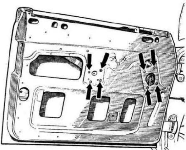
natural_image
Technical line drawing of a car interior panel with mounting holes and structural elements (no text or symbols)Fig.12.13. Location of the screws securing the window winding mechanism

natural_image
Illustration of a hand inserting or adjusting a component into a device casing (no text or symbols visible)Fig.12.14. Removing the window winding mechanism
16 Door locks Mk 1 cars - removal and refitting
1 The door lock mechanism as fitted to Mk 1 cars is shown at Fig.12.15.
2 To remove the lock, first take off the door trim casing in the manner described in Section 11.
3 Disconnect the connecting link, which is retained by a spring, from the dowel at the rear of the lock between the door frame.
4 Take out the four cross headed screws which secure the lock to the end of the door frame.
5 Remove the three screws which secure the remote control to the door frame and now withdraw the mechanism.
6 Unscrew the nut and screw inside the door which retain the outside push button handle.
7 When refitting the lock, first of all secure it loosely to the door and it should be noted that on rear door locks a shorter screw is fitted in the front elongated hole (J) of the remote control unit.
8 Tighten the four screws holding the lock unit first and then align the remote control unit by sliding it as far as possible towards the lock unit and in this position the operating lever (K) will be in contact with the lock case as shown in the drawing. Tighten down on the three securing screws.
9 The plunger housings on the outside door handles are stamped "N.S" (near side) and "O.S" (off side) and the appropriate handle, with its two seating washers, should be held in position on the door panel and the clearance between the plunger (L) and the lock contactor (M) checked through the aperture in the inner door panel.
10 The clearance should be 1/32" (0.8 mm) but before making any adjustment, turn the plunger operating lever (N) to the unlocked position and depress the push button.
11 With the push button depressed, release the locknut (O) and screw the plunger bolt (L) in or out as required and retighten the locknut before releasing the push button.
12 Before fitting the handle to the door attach the extendable connecting link (F) (a rigid link is used on the rear doors) to the plunger operating lever (N) and retain it by its circlip. The link must be fitted so that the bent part at the top is inclined towards the outside handle.
13 Now manoeuvre the connecting link through the handle aperture and allow it to hang downwards inside the door so that the handle with its seating washers can be finally fixed to the door.
14 The plunger operating lever (N) should now be turned to the locked position so that the location holes in the operating lever and the plunger housing are in line and to hold it in this position, insert a short length of 1/8" (3.2 mm) rod through the aperture in the inner door panel and through the locating holes. As the
window channel in the front doors may partially obscure the plunger housing, slacken off the nut which holds the bottom of the rearmost window channel to the bracket in the door and now push the window channel out of the way.
1.5 Check that the remote control cam is set in the locked position and for the front doors, is retained by the peg (H).
16 One of the holes in the bottom of the connecting link (F) can now be aligned with the dowel (G), press it into position where it will be retained by the spring (E).
17 Close the door and check the lock for correct operation and make sure that its position in relation to the striker plate has not been upset.
units need be removed if required.
4 Take off the outside handle base plate assembly by removing the two nuts (I) (two screws were used on the rear doors of early models).
5 The outside push button handle is removed by taking off the two nuts (J) but we suggest you leave it in position unless it is required to fit a new handle.
6 When refitting remote controls they must be in the locked position. You will find that a new remote control is supplied pinned in the locked position as illustrated at (L).
7 Loosely fit the remote control and the lock to the door and hold in position by their screws (G) and (H). On later model cars
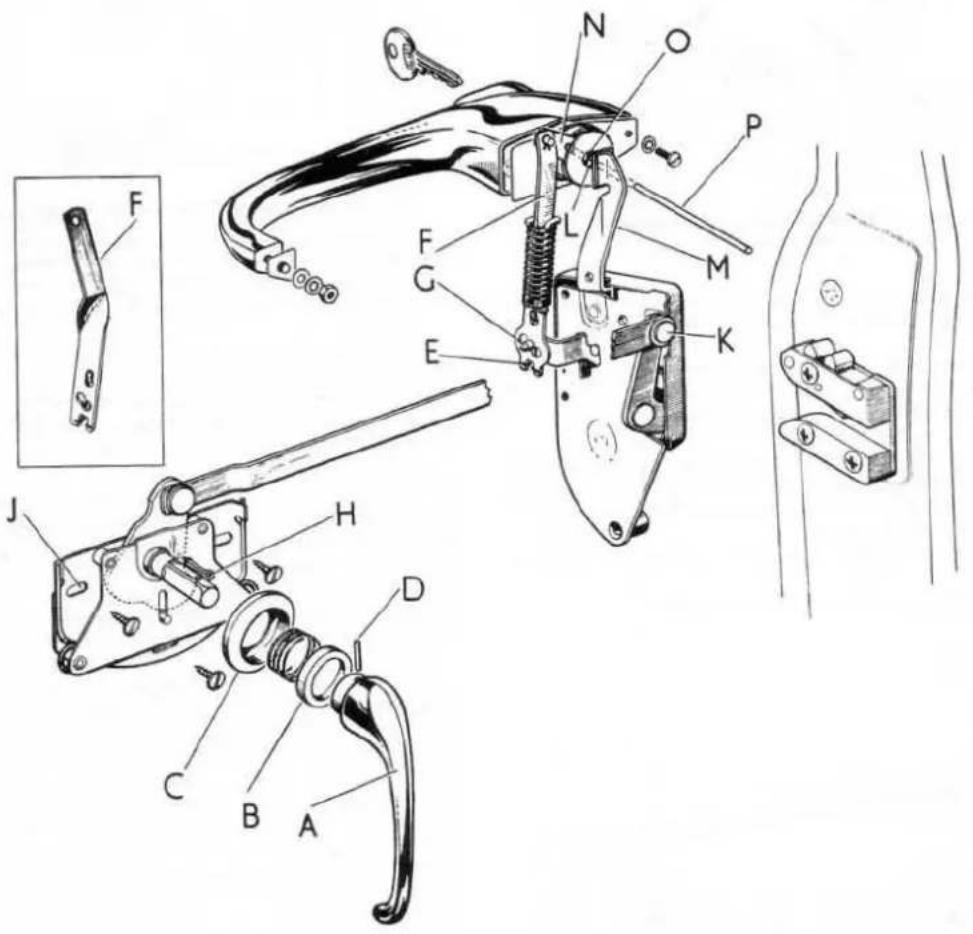
Fig.12.15. The Mk 1 door lock mechanism
17 Door locks Mk 2 and later cars - removal and refitting
which have the remote control as a separate unit, the connecting link has to be attached to the dowel on the operating lever (M) with a waved and plain washer between the lever and the connecting link. The assembly is retained by a spring clip.
- Now tighten the screws (G) holding the lock unit and then align the remote control unit by sliding it, on its elongated holes, towards the lock unit. In this position the operating lever (M) will be in contact with the lock case and the three securing screws must now be tightened.
9 If the outside push button handle was removed it should now be refitted. Make sure that the packing washer (N) is fitted to the front fixing stud and now locate the handle on the door, fit
the shakeproof washers followed by the nuts (J) and tighten down.
10 The base plate assemblies are stamped LH or RH. Place the appropriate assembly in position inside the door panel and check the clearance between the push button plunger (O) and the lock contactor (P). The clearance should be 1/32" and, if adjustment is necessary, slacken the locknut (Q) and screw the plunger bolt (O) in or out as required. Retighten the locknut when the adjustment is correct.
11 Now attach the connecting link (E) (Ea for rear doors) to the dowel on the plunger operating lever (R) and then fit the circlip. The links must be fitted in the positions shown in Fig.12.16 but the extendable link used on early models is fitted in the reverse direction and the middle of the three holes are used as shown at the inset at the bottom right hand of the Figure. The old pattern link should be replaced by the latest type if practicable.
12 Secure the base plate in position by tightening down on the two bolts (I).
13 Check that the remote control cam is set in the locked position and is retained by the split pin (L) as illustrated. On the
rear doors the operating lever (R) is pegged in the locked position, before fitting the link (Ea), by inserting a short length of 1/8" diameter rod (S) through the base plate as shown.
14 The links (E and Ea) are provided with three holes at the bottom end and it will be found that one of these holes will align with the dowel (F) on the intermediate lever. Press the link on to the dowel and it will be automatically retained by the spring clip.
15 Take out the split pin (L) and the piece rod (S) and now check the door locking operation.
16 Depress the push button and make sure that the plunger (O) clears the lock contactor (P). Now set the remote control in the unlocked position when the plunger (O) should pass squarely behind the lock contactor (P) and come into contact with it when the push button is operated.
17 Grease the accessible moving parts of the lock and remote control mechanism and then introduce a few drops of thin oil into the oil hole (T) and into the private lock key slots.
18 Finally refit the door trim casing.

Fig.12.16. Latest type door lock mechanism
18 Windscreen - removal and refitting
Replacement of a windscreen is one of those jobs which you would be well advised to leave to a professional. However, if you decide to do the job yourself, the procedure is as follows.
1 Release the catch and pull the wiper arms off the posts.
2 Prise the chrome finisher off the rubber seal round the windscreen but for Mk 2 and later models, first prise off the two chrome finisher pieces which secure the ends of the encircling finisher.
3 For later models, extract one end of the rubber insert which is under the chrome finisher, and withdraw it completely.
4 Now for both models, run a thin bladed, but blunt, tool around the windscreen to break the seal between the rubber and the windscreen aperture flange.
5 The windscreen is now removed from Mk 1 models by inserting a piece of flat metal between the top of the windscreen aperture flange and the sealing rubber. With a block of wood on the glass for use as a fulcrum and using the piece of metal as a lever, force the windscreen inwards. Repeat this all along the top of the windscreen until it can be withdrawn into the car.
6 The windscreen on Mk 2 and later cars however, is removed by striking the glass with the flat of the hand from inside the car, start in one corner and work towards the bottom and then carry on all round the windscreen until it can be withdrawn from outside the car.
7 Remove the rubber seal from the windscreen flange.
8 Clean all old sealing compound from the windscreen flange.
9 If the windscreen has been broken by some outside agency, carefully clean away all trace of glass from the rubber if it is being used again, but if the screen was of the toughened glass type the rubber should be replaced as small particles of glass may impregnate the rubber and cause breakage of the new windscreen.
10 If the glass broke due to some unknown cause, examine the windscreen aperture flange for irregularity in the metal which, if present should be filed down as this too could be the cause of a new screen breaking.
11 Examine the rubber, if it is being re-used, for cuts and signs of perishing. If the condition of the rubber is at all doubtful it is advisable to replace it because if a perfect seal is not obtained when the screen is refitted it can only result in rain getting past
the rubber especially when driving at high speed in wet weather. 12 Now for Mk 1 cars, attach the rubber to the windscreen with the flat side of the rubber towards the rear and with the join preferably at the bottom. Thread some strong cord (blind cord is ideal) around the rubber groove into which the flange of the windscreen aperture fits and leave the tow loose ends of the cord at the top of the windscreen.
13 Next, working from inside the car, offer up the screen to the aperture with the top edge foremost and keeping the screen as low down at the back of the instrument panel as possible. Have an assistant to exert steady hand pressure at each side of the screen whilst, from outside of the car, you pull on the cord to lip the edge of the rubber over the flange as illustrated in Fig.12.17. 14 For Mk 2 and later model cars, first fit the rubber to the windscreen aperture with the flat side of the rubber to the rear and the joint at the bottom.
15 Two special tools are used when fitting the windscreen and these are illustrated at Fig.12.18. Tool "A" is used to lift the rubber over the glass and tool "B" is used when refitting the rubber sealing strip. You will find that these tools will make the job much easier and every effort should be made to borrow them if you decide to replace the screen yourself.
16 Working from outside the car and with the help of an assistant, offer up the glass to the rubber and, working from the bottom of the glass, use tool "A" to lip the rubber over the glass as shown in Fig.12.19.
17 Having got the glass seated in the rubber, use tool "B" to insert the rubber sealing strip (Fig.12.20) with the rounded wide edge of the strip to the outside.
18 It is most important for all models that the glass is fitted equally. DO NOT fit one end and then try to fit the other.
19 It is now necessary to force sealing compound into the joints and the procedure for this is the same for all models. Use a pressure gun, as illustrated in Fig.12.21, filled with a sealing compound and fitted with a copper nozzle so that the glass will not be scratched. Apply the nozzle of the gun between the metal body flange and the rubber and fill it all round with sealer and now repeat the operation to seal between the glass and the rubber. Excess sealing compound can be removed with a rag dampened with white spirit, do not be too lavish with the white spirit as it is advisable to prevent it running into the sealer.
20 Coat the inside of the chrome strip with a liberal layer of Bostik 1251 and allow it to become tacky. Fit the chrome strips,

natural_image
Line drawing of a person adjusting a car's side mirror, showing the driver inside (no text or symbols)Fig.12.17. Fitting the windscreen to Mk 1 cars

natural_image
Line drawing of a welding torch labeled A and B, showing external components without any text or symbols.Fig.12.18. Special tools used for fitting the windscreen to Mk 2 and later type cars

natural_image
Illustration of a hand using a tool to cut or mark a piece of material, no text or symbols presentFig.12.19. Lipping the windscreen rubber using tool A

natural_image
Illustration of a hand holding a tool near a coiled cable or wire (no text or symbols visible)Fig.12.20. Using tool 'B' to insert the windscreen sealing rubber

natural_image
Illustration of hands using a tool to lift or lift a car wheel (no text or symbols present)Fig.12.21. Sealing the windscreen
note that they are "handed", and with a hook (Use tool "A" if available) lip the rubber over the strip and continue all the way round. The centre chrome clips can now be fitted, treat them with Bostik 1251 and after ensuring that the more acute bend on each centre clip is facing away from the glass, place them in position lifting the rubber as before.
21 Refit the windscreen wiper arms and blades.
19 Rear window glass - removal and refitting
1 This also is one of those jobs best left to a professional but it is not an impossible task for an amateur and if you decide to do it yourself, proceed as follows.
2 If a heated rear window is fitted, disconnect the battery and then, from inside the luggage compartment, disconnect the two leads which will be found at the top of the compartment just below the window.
3 Prise off the chrome finishing strip from the outside of the rubber.
4 Insert a tool between the rubber and the rear screen aperture and run it completely round the rubber moulding to break the seal.
5 Working from inside the car, exert sudden pressure on the glass to remove it.
6 Remove all trace of old sealer from the flange.
7 If the rear glass was broken, make sure that all particles of glass are removed and that the rubber is thoroughly cleaned. If breakage of the glass cannot be accounted for, examine the window aperture flange for irregularities in the metal and if any are found they should be filed away otherwise the new glass may break at an early date.
8 Examine the rubber for cuts or signs of perishing. We advise replacement of the rubber if its condition is at all doubtful.
9 Place the rubber around the glass without any sealer at this stage.
10 Thread some strong cord (blind cord is ideal) twice around the aperture groove and leave the two loose ends at the inside top of the window.
11 Have an assistant inside the car. Offer up the glass, with rubber attached, to the window aperture. Insert one end of the glass and lip the rubber over the aperture flange from inside the car.
12 Travel round the glass exerting sudden pressure from inside the car, whilst your assistant inside the car lips the rubber over the metal aperture by pulling on the cord but taking care not to pull directly against the rubber as this may tear it.
13 Now refer to paragraph 19 of Section 18 and apply a sealing compound and treat and replace the chrome strip in the same manner as described for the windscreen.
14 Finally, if a heated rear window is in use, remake the connections or, if a heated rear window is being fitted for the first time, refer to the appropriate wiring diagram in Chapter 10
for the necessary wiring and connections.
20 Facia panels - removal and refitting
Information on the method of removing and refitting the centre facia panel of Mk 1 cars and the right and left hand panels of all models will be found in Chapter 10 under the Sections dealing with the removal and refitment of the instrument panel and the windscreen wiper mechanism wheel boxes respectively.
21 Radiator grille - removal and refitting
1 Open the bonnet and remove the two setscrews securing the bonnet catch striker plate (Fig.12.22). Take off the plate.
2 Remove the setscrew with its plain and serrated washers and cup which hold the top of the grille to the body.
3 Unscrew the four nuts (five in the case of Mk 1 cars and six in the case of early 2.4 litre models) and remove the small angle brackets which secure the grille to the body. Lift off the grille (Fig.12.23).
4 The centre chrome strip of later models can now be removed by taking off the two bolts which hold it at the bottom of the
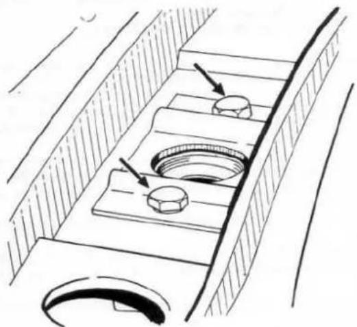
natural_image
Technical line drawing of a mechanical component with two circular features and directional arrows indicating assembly or movement (no text or symbols)Fig.12.22. Location of the setscrews securing the bonnet catch striker plate

natural_image
Technical line drawing of a mechanical component with internal channels and fasteners (no text or symbols)Fig.12.23. Showing the mounting points for the radiator grille
grille and the two screws holding it at the top.
5 Reassembly of the radiator grille and its refitment to the car is the reverse of the above sequence.
22 Bonnet lock - removal, refitting and adjustment
1 Open the bonnet and, using a thin spanner, slacken the locknut at the top of the peg.
2 Using the screwdriver slot in the peg, unscrew it and remove it complete with the locknut, two washers and the spring (Fig.12.24).
3 Now remove the radiator grille in the manner described in Section 21.
4 Slacken the nut securing the bonnet release cable and then withdraw the cable from the release lever.
5 Remove the striker plate, the catch plate, the base plate, spacers and spring.
6 Moving inside the car, take off the dash casing under the steering wheel by removing the three screws and, if applicable the bezels to the speedometer trip and the clock remote controls.
7 Unscrew the locknut holding the bonnet lock abutment to the reinforced panel and the release cable can now be withdrawn.
8 Refitting is the reverse of the above procedure but it will be necessary to adjust the bonnet lock peg before the locknut is tightened. The peg is correctly adjusted when there is approximately 1/16 inch (1.5 mm) movement between the catch plate and the peg, this is checked by closing the bonnet and then pressing down at the front, against the spring pressure, and observing the amount of movement. If the peg is screwed in too far you will find it difficult, if not impossible, to close the bonnet and considerable effort will be required to operate the catch.

natural_image
Line drawing of a hand using a tool to adjust or install a mechanical component (no text or symbols present)Fig.12.24. Removing the bonnet lock peg
23 Bonnet - removal and refitting
1 Open the bonnet and mark the position of the hinges for ease of location on refitment.
2 Slacken the two setscrews to each hinge and then obtain the help of an assistant to support the bonnet.
3 Remove the setscrews from each hinge and then lift the bonnet clear of the car and store it where it will not be damaged.
4 Refit the bonnet in the reverse order to the above, align the hinges with your marks and tighten down on the setscrews.
5 Close the bonnet and check that it is fitting correctly, if adjustment is required, slacken the hinge setscrews and move the bonnet until it is properly aligned in the body and is locking correctly. Tighten the setscrews.
24 Luggage compartment lid and hinges - removal and refitting
1 Disconnect the battery and then, from inside the luggage compartment lid, disconnect the electrical connections to the reverse/number plate light and then remove the setscrew securing the earth wire to the lid.
2 Withdraw the harness from the clips on the lid and then remove the two metal straps which hold the reverse lamp cable to the right hand hinge.
3 Mark the position of the hinges on the lid for ease of location when refitting.
4 Slacken the four setscrews holding each hinge to the lid and then have an assistant to support the lid whilst you remove the bolts with their plain and serrated washers. Lift off the lid.
5 Mark the position of the hinges on the body and then remove them by taking out the securing setscrews with their plain and serrated washers.
6 Refitting is the reverse of the removal sequence but check the lid for correct engagement with the lock. If adjustment is required, slacken the four setscrews securing the lock striker to the lid (Fig.12.25) and then move the striker in the elongated holes until the lock operates correctly and does not rattle.
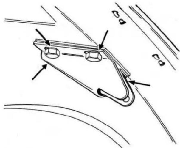
Fig.12.25. Showing means of adjustment for the boot lid striker
25 Front bumper and over-riders - removal and refitting
1 The attachment points for the front bumper are shown in Fig.12.26.
2 Take off the nuts, plain and spring washers to the chrome bolts at each side angle bracket.
3 Take off the nuts securing the bumper to the inner brackets, on Mk.1 cars these nuts also secure the over-riders.
4 Now slacken the nut securing one of the angle brackets to the outer bracket and turn the angle bracket through 90°. The bumper can now be withdrawn.
5 The over-riders on later models are held to the bumper by a nut and plain and serrated washers and when these are removed the over-rider and the beading can be lifted off.
6 Refitting is the reverse of the above removal sequence.
26 Rear bumper and over-riders - removal and refitting
1 The attachment points for the rear bumper are shown in Fig.12.27.
2 Remove the setscrews with the plain and serrated washers which hold the bumper to the two side mounting brackets.
3 Remove the two large setscrews which secure the bumper to the two mounting rubbers (inner position) and then lift off the bumper.
4 The mounting rubbers can be removed by taking off the two nuts holding each to the wings and reinforcement panels.
5 Remove the over-riders by taking off the securing nut, the over-rider and the beading can now be removed from the bumper.
6 Refitting is the reverse of the above removal sequence.
27 Petrol filler lid - removal and refitting
1 The petrol filler lid assembly is shown in Fig.12.28.
2 Remove the return spring. This is quite a strong spring and removal will be made easier by opening the lid to its full extent and then looping a length of strong cord through the eye of the spring. Pull on the cord lifting upwards and at the same time partially close the door and the spring should lift off the anchorage.
3 Remove the two setscrews securing the lid and hinge to the inside wall of the filler cap compartment.
4 Remove the setscrews and washers securing the hinge to the lid.
5 Refitting is the reverse of the above using a similar technique

natural_image
Technical line drawing of a car's front suspension system showing wheel, tire, and brake components (no text or labels)Fig.12.26. The attachment points for the front bumper

natural_image
Technical illustration of a car's front and side views showing engine, dashboard, and steering wheel components (no text or symbols)Fig.12.27. The attachment points for the rear bumper
for refitting the spring on its anchorage as was used for its removal.
- Finally close the lid and align it to fit in its recess in the body panel: this is done by moving it as necessary in the elongated holes in the hinge.

natural_image
Technical line drawing of a mechanical component with internal parts and arrows indicating assembly (no text or symbols)Fig.12.28. Attachment points for the petrol filler lid and hinge
28 Heater unit (Fig.12.29) - removal and refitting
1 Drain the coolant from the radiator and cylinder block in the manner described in Chapter 2.
2 Disconnect the battery.
3 Remove the two screws which hold the side panels each side of the heater control panel.
4 Disengage the water tap control wire at the rear of the panel by slackening the screw securing the outer casing and then slackening the screw securing the inner wire to the lever.
5 Unclip the heater air distribution wire from the spring clip on the lever.
6 Now move outside the car and first remove the bonnet as described in Section 23. Although the heater unit can be removed without taking off the bonnet we advise its removal as you will find you have more room and light in which to work.
7 Unscrew the wing nut in the centre of the paper element air cleaner (if applicable) and remove the complete air cleaner.
8 Disconnect the two wires to the fan motor at their snap
connectors and fold them out of the way.
9 Slacken the jubilee clips and pull off the water hose at the heater control tap and at the pipe leading the heater matrix.
10 Now unscrew the two bolts and the three nuts on the studs which secure the heater body to the scuttle.
11 Withdraw the heater body and control wires and pull out the demister hoses from the sealing rubbers.
12 Details of the method of removing the fan motor from the heater unit are given in Chapter 10.
13 Refitting the heater unit is the reverse of the above operations but before fitting the demister hoses, smear some sealing compound around the holes of the diameter sealing rubber shown in Fig.12.30.
14 When refitting the control cables, place the lever "A" in Fig.12.31 into the fully open (HOT) position, that is, as far as possible towards the heater. Similarly place the control lever in the car to the fully HOT position and then feed the control wire through the lever bracket couplings and tighten the screw which secures the wire to the lever and now tighten the screw holding the outer casing to the anchorage (shown as "A" and "B" respectively in Fig.12.32.
15 Press the flap operating lever, "B" in Fig.12.31, located on the side of the heater box, into the fully shut "screen" position and similarly place the distribution control lever in the car into the screen position. Feed the control wire through the lever bracket coupling and then tighten the screw securing the wire to the lever and the screw holding the outer casing on the bracket. 16 Refill the system with coolant and check for leaks at the pipe unions.
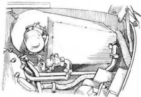
natural_image
Illustration of a cartoon character inside a vehicle or industrial space, with no visible text or symbols.Fig.12.29. The heater unit and water control tap
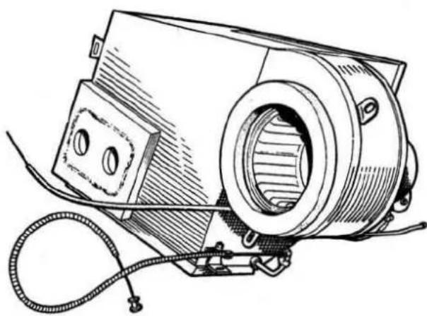
natural_image
Technical line drawing of a mechanical device with no visible text or symbolsFig.12.30. The demister duct

natural_image
Technical line drawing of an electric motor with labeled components A and B (no text or symbols beyond labels)Fig.12.31. Setting the heater flap control
29 Heater water control tap - removal and refitting
1 Drain the coolant from the system in the manner described in Chapter 2.
2 Refer to Fig.12.29 which shows the location of the tap.
3 Slacken the jubilee clip securing the water pipe to the tap and then pull the pipe off the tap.
4 Slacken the bolt securing the outer cover of the control wire to the bracket on the tap and then slacken the locknut and setscrew which secure the control wire to the valve lever on the control tap.
5 Withdraw the remote control wire from the tap.
6 Slacken the locknut and the setscrew which secure the heater control flap wire to the valve lever and then withdraw the wire.
7 Remove the setscrews holding the tap to the heater body and remove the tap and the rubber sealing washer.
8 Refitting is the reverse of the above sequence but replace the rubber hose to the tap and the rubber sealing washer if their condition is at all doubtful.
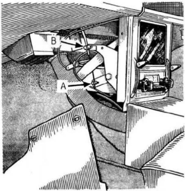
Fig.12.32. Setting the heater operating lever
30 Exhaust system - general
The exhaust system fitted to 2.4 litre Mks 1 and 2 models, illustrated at Fig.12.33, consists of a branched down pipe and a single silencer and tail pipe. There are slight differences in the system fitted to the two models. These are that on the Mk 2 car the mounting bracket is integral with the silencer and the tail pipe is of slightly different shape.
All other models are provided with what is in effect two separate exhaust systems as can be seen from the illustration at Fig.12.34. Except for the 3,4 litre Mk 1 and the down pipes of the 240 model, all later cars have identical components in the system.
31 Exhaust system - removal and refitting
1 The following paragraphs refer to 2.4 litre Mks 1 and 2 cars.
2 Remove the nut and bolt securing the tail pipe to the bracket under the rear bumper on the left hand side for Mk 2 models and on the right hand side of the car in respect of the Mk 1 range.
3 Slacken the clip securing the tail pipe to the silencer and remove the tail pipe.
4 Slacken the clip securing the silencer to the down pipe.
5 Remove the nuts and bolts securing the silencer to the rubber mounting brackets and remove the silencer. Whilst doing this, try not to put too much strain on the flexible portion of the down pipe.
6 Remove the four nuts and washers securing each branch of the downpipe to the exhaust manifold.
7 Take off the nut and bolt which secures the downpipe to the bracket on the bellhousing and the downpipe can now be removed. Discard the copper seals fitted between the downpipe and the exhaust manifold flanges.
8 Follow the same sequence as the above to remove the twin exhaust system from the other models except, of course, two clips have to be removed when disconnecting the downpipes and the tail pipes from the silencer assembly.
9 Considerable difficulty may be experienced, on all models, in separating the tail pipes and the downpipes from the silencer, there is no easy way of doing this and each case will have to be treated on its merits. All we can suggest is that you bend each section of the silencer pipe extension up slightly and then break the joint by tapping all round or even inserting a thin screwdriver
in the join.
10 Refitting is the reverse of the removal sequence but always use new copper sealing rings between the downpipe and the exhaust manifold.
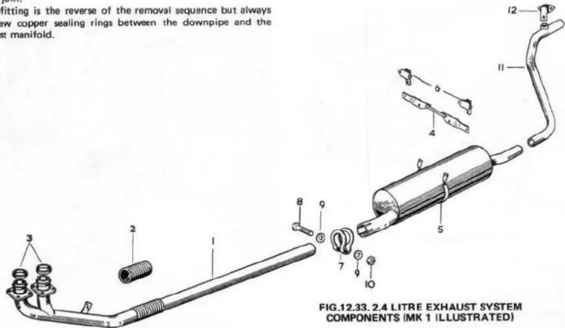
1 Exhaust downpipe 7 Clip
2 Flexible pipe 8 Bolt
3 Sealing ring 9 Washer
4 Adaptor mounting plate 10 Nut
5 Exhaust silencer 11 Tail pipe
6 Rubber mounting 12 Rubber mounting
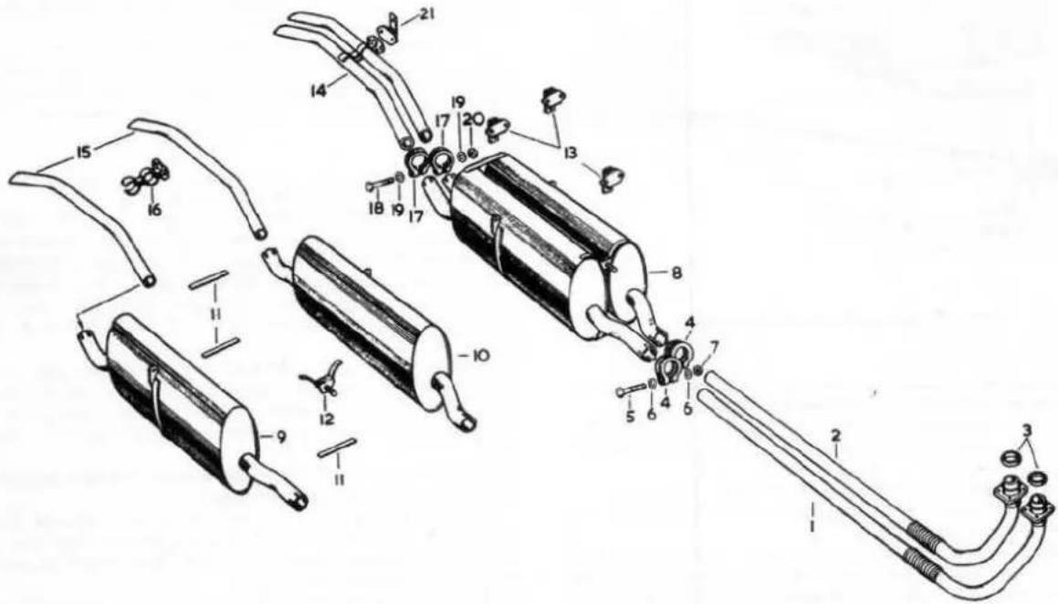
FIG.12.34. EXHAUST SYSTEM COMPONENTS 3.4, 3.8 LITRE AND 240, 340 MODELS
1 Front downpipe
2 Rear downpipe
3 Copper sealing ring
4 Clip
5 Bolt
6 Plain washer
7 Nut
8 Twin silencer assembly
9 Inner silencer
10 Outer silencer
11 Strap
12 Strap assembly
13 Rubber mounting
14 Exhaust tail pipe
assembly
15 Tail pipe
16 Mounting bracket
17 Clip
18 Bolt
19 Plain washer
20 Nut
21 Rubber mounting
32 Wheels and tyres - general
All cars are fitted with pressed steel disc wheels as standard. Wire spoke wheels were available as optional equipment on most models. The wire spoke wheels fitted to early Mk 1 models had either 60 or 72 spokes per wheel and these should only be fitted to individual cars in complete sets.
Tyres, size 6.00/6.40 x 15, supplied with the later model cars were Dunlop Gold Seal C.41 (tubeless) for use with disc wheels and Dunlop RS5 (tubed) for use with disc or spoked wheels. Dunlop SP 41 (radial) are offered for optional fitment.
33 Tyre inflation pressures
It is important to maintain the tyre pressures at the correct figures as given below as incorrect pressure will affect the steering, riding comfort and tyre wear.
The pressure should be checked when the tyre is cold and not when it has attained its normal running temperature when an increase in pressure due to increased tyre temperature is to be expected and is allowed for in the quoted pressure when cold. Always ensure that the caps are fitted to the valves as they not only prevent the ingress of dirt but also act as a secondary seal to the valve core.
34 Wheel alignment and tyre wear
It is most important that correct alignment of the front wheels (see Chapter 11) is maintained as misalignment causes a tyre tread to be scrubbed off laterally because the natural direction of the wheel will differ from that of the car.
Misalignment of the front wheels is indicated by an upstanding sharp "fin" thrown up on the edge of each pattern rib. "Fins" on the inside edges of the ribs, that is the edges nearest the car, indicate excessive "toe-in" whilst those on the outside edges show that the wheels are "toeing-out".
Road camber affects the direction of the car as it imposes a side thrust and the car drifts towards the nearside and this is instinctively, although perhaps not knowingly, corrected by steering towards the centre of the road. This action results in a crabwise motion of the car as shown in exaggerated form in Fig.12.35 which also illustrates why nearside tyres are very sensitive to too much "toe-in" and offside tyres to "toe-out".
35 Tyre replacement and wheel interchanging
It is common practice to interchange wheels at regular intervals with the object of getting even wear on the tyres. However, changing wheels with part worn tyres from the rear to the front positions can cause very adverse changes in steering characteristics. It is our experience that this can result in "wander" and vagueness in "feel" of the steering as is usually associated with misalignment of the front wheels. We recommend, therefore, as do Jaguar Cars Ltd, that wheels with part worn tyres are not transferred from the rear to the front positions. When the time comes to change the rear tyres, and these will invariably wear quicker than the front, fit these wheels with the new tyres on the front and transfer those from the front, which should still have a useful tyre life left, to the rear. If the tyre on the spare wheel is new this can, of course, be brought into use in the front position and one of the rear wheels with a new tyre then held as the spare.
36 Wire spoke wheels - removal and refitting
The removal and refitting of the Dunlop - 72 wire spoke wheels requires a slightly different technique to that employed with disc wheels attached with the conventional five nuts to

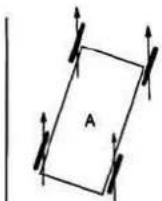


A. WHEELS PARALLEL IN MOTION: TYRE WEAR EQUAL
B. WHEELS TOED-OUT IN MOTION; RIGHT FRONT TYRE WEARS FASTER
C. WHEELS TOED-IN IN MOTION; LEFT FRONT TYRE WEARS FASTER
Fig.12.35. Showing how road camber and front wheel misalignment affect tyre wear
studs. The spoked wheels are mounted on splined hubs and are held in position by knock-on hub caps as illustrated in Fig.12.36. The hub caps are marked, as shown in the drawing, to indicate the side of the car to which they fit and the direction in which they have to be turned for undoing. But, in case the markings have been obliterated, it must be remembered that the nearside caps, that is the left hand side of the car looking forward, have a right hand thread and undo by turning in an anti-clockwise direction. The caps fitted to the offside of the car, right hand side looking forward, have a left hand thread and undo by turning in a clockwise direction.
1 To remove the wheels, place the car on level ground and prepare for jacking in the normal manner.
2 If the rear wheel is to be changed, open the appropriate rear door and undo the two screw headed quick release fasteners holding the nave plate. Lower the nave plate to disengage the lip with the body and then pull forward to disengage the peg at the rear.
3 Before lifting the car, slacken, but do not remove the hub cap by striking it in the appropriate direction with a copper or hide faced mallet.
4 Raise the car and unscrew the hub cap and then pull the wheel outwards off the splines.
5 To refit the wheel, mount it on the splined hub but try not to damage the "lead-in" to the splines as this will make fitting, and subsequent removal, difficult.
6 Fit the hub cap and tighten as much as possible by rotating it in the required direction (anti-clockwise for right hand side and clockwise for left hand side).
7 Lower the car and then finally tighten the hub fully, using the copper or hide faced mallet.
8 Refit the nave plate to the rear wheel arch (if applicable).
TYRE PRESSURE CHART
On all the models it is advisable to increase the REAR tyre pressure by 4 lbs. per sq. in. (.28 kg/cm ^2 ) when undertaking a long journey with a full load of passengers and luggage.
2.4 LITRE AND 240 MODELS
DUNLOP GOLD SEAL C.41 (TUBELESS) TYRES
| Front | Rear | |
| For conditions where maximum performance with sustained speeds is being used, or for touring conditions where the car is fully laden: | 33 lb/in ^2 (2,3 kg/cm ^2 ) | 33 lb/in ^2 (2,3 kg/cm ^2 ) |
| For normal motoring with maximum speed up to 90 m.p.h.(145 k.p.h.) | 28 lb/in ^2 (2,0 kg/cm ^2 ) | 28 lb/in ^2 (2,0 kg/cm ^2 ) |
| For two-up normal motoring to give maximum comfort it is permissible and may be found desirable to reduce the rear tyre pressures by 3 lb/in (0,2 kg/cm). |
2.4, 3.4 AND 3.8 LITRE MARK 2, 240 AND 340
DUNLOP RS5 TYRES
| Front | Rear | |
| For conditions where maximum performance with sustained speeds is being used, or for touring conditions where the car is fully laden: | 33 lb/in ^2 (2,3 kg/cm ^2 ) | 33 lb/in ^2 (2,3 kg/cm ^2 ) |
| For normal motoring with maximum speed up to 110 m.p.h.(176 k.p.h.) | 28 lb/in ^2 (2,0 kg/cm ^2 ) | 28 lb/in ^2 (2,0 kg/cm ^2 ) |
| For two-up normal motoring to give maximum comfort it is permissible and may be found desirable to reduce the rear tyre pressures by 3 lb/in ^2 (0,2 kg/cm ^2 ). |
DUNLOP SP 41 TYRES (OPTIONAL)
| For conditions where maximum performance with sustained speeds is being used, or for touring conditions where the car is fully laden: | 36 lb/in ^2 (2.5 kg/cm ^2 ) | 36 lb/in ^2 (2.5 kg/cm ^2 ) |
| For normal motoring with maximum speed up to 100 m.p.h.(160 k.p.h.) | 30 lb/in ^2 (2.1 kg/cm ^2 ) | 30 lb/in ^2 2.1 kg/cm ^2 ) |
For two-up normal motoring to give maximum comfort it is permissible and may be found desirable to reduce the rear tyre pressures by 3 lb/in ^2 (0,2 kg/cm ^2 ).
37 Wire spoke wheels - repair and adjustment
Wire spoke wheels should be examined at regular intervals for damage to looseness of spokes. Either fault should be rectified without delay as it is likely that the wheel will be out of truth in a lateral or radial direction or a combination of both.
Spokes, 24 long and 48 short per wheel, with their securing nipples are available as spares and although their fitment presents no very great problem you may find difficulty in trueing the wheel as a free running trueing stand, and a certain amount of expertise are called for. However, if you wish to repair the wheel yourself, and have no access to a trueing stand and provided there is no play in the bearings of the front wheel hub on your car you may consider using the hub as a trueing stand, but it will make for awkward working.
The following paragraphs assume that the wheel is being completely rebuilt.
1 Place the wheel centre and the rim on a flat surface with the valve hole upwards in the 6 o'clock position.
2 Refer to Fig.12.37.
3 Starting at the valve hole fit one A, B, C and D spoke to produce the pattern shown in the drawing.
4 Once you have established the correct pattern, remove the A and B spokes.
5 Fit the nipple to the D spoke and screw it up finger tight. Leave the C spoke loose and without a nipple fitted.
6 Assemble all the D spokes and screw up the nipples finger tight.
7 Now insert all the C spokes through the hub shell but do not fit the nipples.
8 Attach all the B spokes and fit their nipples finger tight.
9 Repeat with all the A spokes.
10 Attach the nipples finger tight to all the C spokes.
11 Tighten the two C spokes and the two D spokes on each side of the valve hole until the ends of the spokes are just below the slot in the head of the nipple.
12 Repeat with the two C and two D spokes diametrically opposite the valve hole.
13 Work round the wheel and tighten all the C and D spokes as above.
14 Repeat with all the A and B spokes until the end of these spokes are also just below the slot in the nipple heads.
15 Work round the wheel and tighten the nipples on diametrically opposed spokes until some resistance is felt on all spokes.
16 Now mount the wheel on a trueing stand.
17 Spin the wheel and, with a piece of chalk, mark any high spots near the wall of the rim flange. Tighten the A and B spokes and slacken the C and D spokes in the region of the marks.
Note: No spoke should be tightened to the extent that it is impossible to tighten it further (maximum normal torque is 60 lb f in (0.7 kg f m). If a spoke is as tight as it will go, all the other spokes must be slackened.
18 Carry on until all lateral errors are corrected.
19 Radial errors must now be corrected and this is done by spinning the wheel and marking the high spots on the horizontal tyre seat.
20 Tighten all the spokes in the region of the marks, or, if those spokes are on the limit of tightness, slacken all the others.
21 Now refer to Fig.12.38 and check the "dish" of the wheel. This is the lateral dimension from the inner face of the flanges of the wheel centre to the inner edge of the wheel rim and should be 3.7/16" ± 1/16" (8.73 mm ± 1.58 mm).
22 If the "dish" is in excess of the above dimension, tighten all A and B spokes and slacken all C and D by a similar amount. Conversely, if the dimension is less than that quoted, slacken all A and B and tighten all C and D spokes by a similar amount.
23 If correction for "dish" has been made, it will be necessary to repeat the lateral and radial trueing until the wheel is not more than 0.060" (1.5 mm) out of truth in either direction.
24 If the trueing operation has been completed properly, all the spokes should be uniformly tensioned and to a reasonably high degree. A correctly tensioned spoke should emit a high pitched note when lightly tapped with a hammer. If a nipple spanner of the torque recording type is used, the reading, as stated above, should be in the region of 60 lb f in (0.0 kg f m) for a properly tightened spoke.
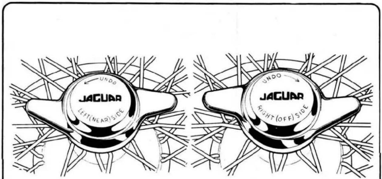
Fig.12.36. Hub caps left and right side
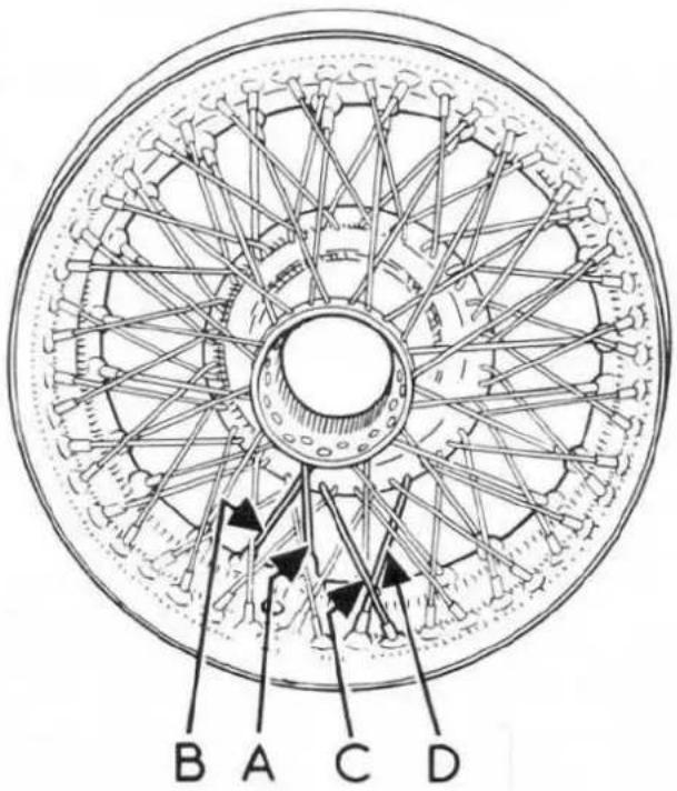
Fig.12.37. Showing the arrangement of spokes

Fig.12.38. Measurement of 'dish' and location of spokes
As this book has been written in the United Kingdom, it uses the appropriate English component names, phrases, and spelling. Some of these differ from those used in America. Normally, these cause no difficulty, but to make sure, a glossary is printed below. In ordering spare parts remember the parts list will probably use these words:
Glossary
Miscellaneous points
An 'Oil seal' is fitted to components lubricated by grease!
A 'Damper' is a 'Shock absorber': it damps out bouncing, and absorbs shocks of bump impact. Both names are correct, and both are used haphazardly.
Note that British drum brakes are different from the Bendix type that is common in America, so different descriptive names result. The shoe end furthest from the hydraulic wheel cylinder is on a pivot; interconnection between the shoes as on Bendix brakes is most uncommon. Therefore the phrase 'Primary' or 'Secondary' shoe does not apply. A shoe is said to be Leading or Trailing. A 'Leading' shoe is one on which a point on the drum, as it rotates forward, reaches the shoe at the end worked by the hydraulic cylinder before the anchor end. The opposite is a trailing shoe, and this one has no self servo from the wrapping effect of the rotating drum.
Index
A
Air cleaners - 50
Anti-freeze mixture - 70
B
Battery
charging - 194
electrolyte replenishment - 194
maintenance and inspection - 193
removal and replacement - 193
Big end - examination and renovation - 43
Bodywork and underframe
bonnet - removal and refitting - 268
body repair - 259
locks and hinges - 250
windscreen - removal and refitting - 266
Braking system
bleeding - 174
drum brakes - removal and refitting - 177
drum brakes shoes and wheel cylinders - 177
disc brakes - 180
master cylinder - 186
servo unit - 187
vacuum reservoir - 189
Bumper bar - removal and refitting - 269
C
Camshaft
examination and renovation - 45
Carburettors
description - 79
adjustment and synchronisation - 79
dismantling and reassembly - 80
examination and repair - 86
float chamber flooding - 88
float needle sticking - 88
jet centering - 89
needle replacement - 90
piston sticking - 86
solex type - 79
SU type - 83
Clutch and activating mechanism
bleeding - 104
dismantling - 107
examination - 107
fork and release bearing - 112
fault diagnosis and remedy - 115
general description - 104
judder - 116
master cylinder - 113
pedal removal and replacement - 116
squeal - 115
slip - 116
spin - 116
Coil - 96
Condenser - 97
Connecting rods - 45
Contact breaker points · 96
Cooling system
draining - 64
flushing and filling - 65
general description - 64
Crankshaft
removal - 40
examination and renovation - 43
replacement - 54
D
Decarbonisation - 48
Differential assembly
dismantling and examination - 165
pinion oil seal - 164
reassembly - 166
(Check Powr-Lok instructions for variations on above)
Disc brakes - 180
Distributor - dismantling - 98
inspection and repair - 99
removal and refitting - 97
Distributor drive
removal - 40
refitting - 57
Doors - removal and refitting - 260
Drum brakes - 177
Dynamo - dismantling and inspection - 194
removal and refitting - 194
reassembly - 196
testing in position - 196
E
Electrical system
Electric clock - 208
fuses - 202
generator - see dynamo - 194
lighting equipment - 204
wiring diagram - 214
Engine
dismantling - 29
examination and renovation - 43
fault diagnosis - 63
final assembly - 61
general description - 20
initial start up after repair - 62
removal with gearbox - 28
removal without gearbox - 28
removing ancillary components - 29
replacement - 61
specifications - 15
F
Fan belt
adjustment - 68
removal and refitting - 68
Facia panel - 267
Fault finding - braking system -
Fault finding - clutch - 115
Fault finding - engine -
Fault finding - ignition - 102
Fault finding - overdrive - 142
Fault finding - flasher circuit - 203
Flywheel
removal - 29
refitting - 56
starter ring - 44
Fuel gauge - 211
Fuel pump
general description - 75
removal and refitting - 77
Fuel system and carburation
general description - 74
specifications - 73
fuel tank - 78
gauge unit - 79
Fuses - 202
G
Gearbox
dismantling - 120
examination and renovation - 127
general description - 120
reassembly - 131
removal and replacement - 120
H
Handbrake adjustment - 183
Headlamps - 204
Heater - removal and refitting - 270
Horn - fault tracing - 207
Hydraulic system - bleeding
brake - 174
clutch - 104
I
Ignition system
coil - 96
fault diagnosis - 101
general description - 96
ignition timing - 99
spark plugs and leads - 100
L
Lights
headlamp adjustment - 204
sealed beam unit - 204
panel and warnings - 204
side, tail and flasher bulbs - 204
Lubrication chart - 8
Lubricants, recommended - 7
M
Main bearings
examination and renovation - 43
removal - 43
Maintenance, see routine maintenance - 9
0
Oil filter - removal and replacement - 41
Oil pump - examination and renovation - 50
removal - 43
replacement - 56
Overdrive
dismantling, overhaul, reassembly - 133
fault finding - 142
general description - 132
operating valve - 139
pump non-return valve - 140
removal and replacement - 140
P
Piston
examination and renovation - 45
reassembly -55
removal - 32
replacement - 55
Piston rings
examination and renovation - 45
removal - 39
replacement - 55
Points, contact breaker - 96
Propeller shaft
general description - 151
removal, inspection, replacement - 154
sliding joint - 156
universal joints - 156
R
Radiator - 65
front grille - 268
Rear axle
axle shaft - 162
differential assembly - 164
general description - 160
pinion oil seal - 164
Powr-Lok - 164
recommended lubricants - 7
s
Spark plugs and leads - 100
Starter motor
brushes - 198
dismantling and reassembly - 198
description - 197
removal and refitting - 197
testing in position - 198
Steering
front wheel alignment - 255
power assisted steering - general - 244
steering box (standard) - removal and refitting - 235
steering box - examination - 237
wheel-234
Sump - replacement - 56
Suspension
general description - 223
specifications
T
Tappets
examination and renovation - 48
Thermostat - 66
Timing chain assembly - 56
Timing chain tensioner - 56
Tyre pressures - 273
U
Universal joints
dismantling - 156
general - 156
reassembly - 157
v
Valves
clearance and adjustments - 59
examination and renovation - 47
guides removal - 32
W
Water pump - 68
Wheels and tyres - 273
Windscreen, removal and refitting - 266
mechanism fault diagnosis and rectification - 203
washer (electrical) - 206
wiper-203
Printed by
J. H. HAYNES & Co. Ltd
Sparkford Yeovil Somerset
ENGLAND
Haynes Owners Workshop Manuals are written with the home mechanic in mind who does not have the luxury of a well equipped workshop nor factory service tools. Each manual covers a specific make and model. A second hand example is purchased and is used as the basis for the manual. Before overhaul begins the author undertakes considerable research into the model range and modification history talking with the manufacturers, dealers, repair specialists and owners.
Each manual presents the dismantling, overhaul and reassembly in a logical sequence describing the component parts in the minutest detail, also included are comprehensive specifications and extensive fault finding charts together with details of routine maintenance.
What the press say...
"These are really worthwhile manuals which can save you a lot of money." Autocar
"Haynes manuals are outstanding for giving the learner mechanic an easy to follow guide to doing most any type of repair or maintenance work on his or her car." Road & Track
". . . written for the intelligent owner who wants to understand the construction and working of his car, and who is not afraid to pick up a spanner and dismantle it." Safer Motoring
"These authentic manuals are actually written from practical experience . . ." Car Mechanics
"Excellent value for money, beginners and experts should find it equally useful, overall a mine of information." Motor
"It is thus opportune that a simply splendid Owners Workshop Manual has just come out. Every imaginable job is illustrated . . ." Autosport
"For the home mechanic Haynes DIY workshop manuals show clearly step-by-step servicing operations in pictures". Sunday Mirror
" . . plus some very useful photographically illustrated step-by-step assembly and re-assembly procedures." Motor
"Another book well worth buying." Hot Car
"All instructions given on a step-by-step basis with a minimum of cross-references and vast number of illustrations roughly one per step. Great use of photographs but well taken and clearly printed." Motor
" . . . written particularly for the do-it-yourself chap with the object and aim of saving money." Cars and Car Conversions
" . . . covers absolutely everything you could wish to know." Popular Motoring
"Every conceivable aspect is covered down to the minutest accessory . . . excellent value for money, and is an invaluable asset." Safer Motoring



- Owners Workshop Manual
- Jaguar Mk 1 and 2 240 and 340 Owners Workshop Manual
- Acknowledgements
- About this manual
- Introduction to the
- Jaguar Mks1 and 2, 240 and 340
- Recommended lubricants
- Ordering spare parts
- Routine maintenance
- Daily before use
- Weekly
- Monthly
- Every 2500/3000 miles (4000/5000 km)
- Every 5000/6000 miles (8000/10000 Km)
- Every 10,000/12,000 miles (16,000/20,000 Km)
- Every 21,000 miles (35,000 km)
- Every 24,000 miles (40,000 km)
- Chapter 1 Engine
- General description
- Major operations with engine in place
- Major operations with the engine removed
- Methods of engine removal
- Engine removal with gearbox - lifting upwards
- Engine removal less gearbox
- Engine removal with gearbox (from underside)
- Separating the engine from the gearbox (manual)
- Separating the engine from the transmission unit (automatic)
- Removal and replacement of gearbox and clutch assembly - with engine installed
- Dismantling the engine - general
- Removing the ancillary engine components
- Oil supply pipes to camshaft - Water pump, crankshaft damper and pulley
- Cylinder head removal - engine on bench
- Cylinder head removal - engine in car
- Camshaft removal
- Valve removal
- thrower
- housing
- choke
- Valve and tappet guide - removal
- Sump, piston, connecting rod and big end bearing - removal
- Gudgeon pin - removal
- Piston ring - removal
- Oil pump assembly - removal
- Distributor drive - removal
- Crankshaft - removal
- Lubrication system · description
- Oil filter - removal and replacement
- FIG.1.15. OIL FILTER – UPWARD POINTING TYPE
- filter.
- Engine - examination and renovation - general
- Crankshaft - examination and renovation
- Crankshaft pulley and damper - examination and renovation
- Big end and main bearings - examination and renovation
- Flywheel - examination and renovation
- Cylinder block - examination and renovation
- Pistons and piston rings - general
- Pistons, piston ring and gudgeon pin - examination and renovation
- Connecting rods - examination and renovation
- Camshaft and camshaft bearings - examination and renovation
- Valves and seats - examination and renovation
- Inlet valve oil seals - general
- Valve springs - examination and test
- Tappets and valve adjusting pads - examination and renovation
- Cylinder head and bore - decarbonisation, examination and renovation
- Air cleaners - maintenance
- Oil bath type:-
- Paper element type:-
- Engine reassembly - general
- Crankshaft - replacement
- Piston and connecting rod - reassembly
- Piston ring - replacement
- Piston · replacement
- Connecting rod to crankshaft - reassembly
- Crankshaft gear and sprocket - reassembly
- Distributor and oil pump drive gear - reassembly
- Oil pump and pipes - reassembly
- Timing gear - assembly
- Timing gear - reassembly to engine
- Timing chain tensioner - reassembly
- Timing cover · refitting
- Oil sump - refitting
- Flywheel and clutch - refitting
- Oil filter - refitting
- Crankshaft damper and pulley - refitting
- Distributor - refitting
- Cylinder head - reassembly
- Valve clearance adjustment
- Important
- Cylinder head - refitting
- Valve timing
- Inlet manifold - refitting
- Cylinder head oil feed pipe - refitting
- Water pump - refitting
- Engine breather assembly - refitting
- Gearbox - refitting
- Final assembly
- Engine replacement
- Engine - initial start up after overhaul and major repair
- Chapter 2 Cooling system
- Cooling system - draining
- Cooling system - flushing
- Cooling system - filling
- Radiator - removal and refitting
- Radiator - inspection and cleaning
- Thermostat - removal, testing and replacement
- Fan - removal and refitting
- Fan belt - removal and replacement
- Fan Belt - adjustment
- Water pump - removal and refitting
- Water pump - dismantling and overhaul
- Temperature gauge and thermal transmitter - general
- Water temperature gauge Mk 1 models - testing, removing and refitting
- Water temperature gauge thermal transmitter Mk 2, 240 and 340 models - testing, removing and refitting
- Anti-freeze - mixture
- Chapter 3 Fuel system and carburation
- Fuel pump - general description
- Fuel pump - removal and replacement
- Fuel pump - dismantling
- Fuel pump - examination
- Fuel pump - reassembly
- Fuel pump - fault finding
- Petrol tank - removal and refitting
- Petrol gauge, tank unit - removal and refitting
- Carburettor Solex B.32 PB - 5 - description
- Carburetters Solex - removal and replacement
- Carburettor (Solex) - dismantling and reassembly
- Carburettor (Solex) - cleaning and inspection
- Carburettors (Solex) - adjustment and synchronisation
- Carburettor (Solex) - sudden break in performance
- Carburettors (Solex) - poor slow running
- Carburettors (Solex) - heavy fuel consumption
- Carburettors (Solex) - failure to respond to throttle opening
- WITH FLOAT CHAMBER COVERS REMOVED
- Carburettors (Solex) - flat spot (engine hot)
- Carburettors (Solex) - difficult starting when engine cold
- Carburettors (Solex) - deterioration of performance
- Carburettors SU type HD 6 and HS 6 - general description
- Carburettor (SU) - removal and replacement
- Carburettor HD 6 - dismantling and reassembly
- Carburettor HS 6 - dismantling and reassembly
- Carburettor SU - examination and repair
- Carburettor SU - piston sticking
- Carburettor SU - float needle sticking
- Carburettor SU - float chamber flooding
- Carburettor SU - water or dirt in the carburettor
- Carburettor HD 6 - jet centring
- Carburettor HS 6 - jet centring
- Carburettor SU - needle replacement
- Carburettors SU - adjustment and tuning - general
- Carburettors SU HD 6 - adjustment and tuning
- Carburettors SU HS 6 - adjustment and tuning
- The auxiliary starting carburettor - description
- The auxiliary starting carburettor - adjustment
- The thermostatic switch - removal and refitting
- Fault diagnosis
- Chapter 4 Ignition system
- Contact breaker points - removal and replacement
- Contact breaker points - adjustment
- Condenser - removal, testing and replacement
- Distributor - lubrication
- Distributor - removal and replacement
- Distributor - dismantling
- Distributor - inspection and repair
- Distributor - reassembly
- Ignition - timing
- Spark plugs and leads
- Ignition system - fault finding
- Fault diagnosis - engine fails to start
- Fault diagnosis - engine misfires
- Chapter 5 Clutch and actuating mechanism
- Clutch system - bleeding
- Clutch pedal - removal and replacement
- Clutch pedal - free travel
- Clutch - removal
- Clutch - dismantling
- Clutch - examination
- Clutch - reassembly
- Clutch - refitting
- Clutch fork and release bearing - removal, examination and refitting
- Clutch master cylinder - general description
- Clutch master cylinder - removal
- Clutch master cylinder - dismantling
- FIG.5.23. EXPLODED VIEW OF THE CLUTCH MASTER CYLINDER
- Clutch master cylinder - examination
- Clutch master cylinder - reassembly
- Clutch master cylinder - refitting
- Clutch slave cylinder - general description
- Clutch slave cylinder - removal
- Clutch slave cylinder - dismantling
- Clutch slave cylinder - examination
- Clutch slave cylinder - reassembly
- Clutch slave cylinder - refitting
- Clutch slave cylinder hydrostatic type - operating rod adjustment
- Removing and refitting a flexible hose
- Fault diagnosis and remedy
- Clutch squeal
- Clutch slip
- Clutch spin
- Clutch judder
- Chapter 6 Gearbox, overdrive and automatic transmission
- Gearbox - removal and replacement
- Gearbox - dismantling
- FIG.6.5. THE GEARS, JC GEARBOX
- Gearbox - examination
- Gearbox - reassembly of type GB and GBM
- Gearbox - reassembly of type JC and JCN
- Overdrive unit - general description
- Overdrive unit - removal from the gearbox
- Overdrive unit "A" Type - dismantling
- FIG.6.28. THE FRONT CASING ASSEMBLY 'A' TYPE UNIT
- FIG.6.29. THE REAR CASING ASSEMBLY 'A' TYPE UNIT
- Overdrive unit - "A" Compact Type - dismantling
- Overdrive unit - examination
- The operating valve - removal and refitting
- The operating valve - adjustment
- The hydraulic system - faulty operation
- Pump valve - removal and refitting
- Pump - removal and refitting
- Accumulator piston and spring - removal and refitting
- Overdrive unit, "A" Type - reassembly
- Overdrive unit, "A" Type Compact - reassembly
- Overdrive unit - refitting to the gearbox
- The overdrive control system
- Overdrive - fault finding
- Overdrive does not engage
- Overdrive does not release
- Clutch slip in overdrive
- Freewheel condition on over-run
- Automatic transmission - general description
- Automatic transmission - fluid level
- Automatic gearbox - removal and refitting
- Torque converter - removal and refitting
- Starter inhibitor/reverse light switch - check and adjustment
- Downshift cable - adjustment
- Selector linkage - adjustment
- Front brake band · adjustment
- Rear brake band - adjustment
- Automatic transmission - fault diagnosis
- Converter diagnosis
- Stall speed test
- Fault diagnosis through road test
- Remedial actions
- above.
- Chapter 7 Propeller shaft and universal joints
- Propeller shaft - removal and replacement
- Divided propeller shaft alignment
- Centre bearing - general description
- Centre bearing - dismantling
- Centre bearing - overhaul
- Centre bearing - refitting
- Sliding joint - dismantling, overhaul and reassembly
- Universal joints - general
- Universal joints - dismantling
- Universal joint - reassembly
- Chapter 8 Rear axle
- Contents
- Specifications
- Special tools
- Note
- Rear axle - removal and replacement
- Rear axle - dismantling for replacement
- Axle shaft, bearing and oil seal - removal and replacement
- Pinion oil seal - removal and replacement
- Pinion - removal
- Differential assembly, conventional type - dismantling
- Differential assembly, Thornton "Powr-Lok" - dismantling
- Differential unit, conventional type - reassembly, adjustment and refitting
- Chapter 9 Braking system
- Bleeding the hydraulic system
- Front drum brake wheel cylinder - dismantling, overhaul and reassembly
- Rear drum brake wheel cylinder - dismantling, overhaul and reassembly
- Disc brake friction pads - removal and refitting
- Front disc brake caliper - removal and refitting
- Rear disc brake caliper - removal and refitting
- Front and rear discs - removal and refitting
- Disc brakes - renewing the brake piston seals
- Handbrake - adjustment
- Handbrake friction pads - removal and replacement
- Handbrake friction pad carriers - removal and refitting
- Handbrake friction ped carriers - dismantling and reassembly
- Brake pedal assembly - removal and refitting
- Master cylinder - removal and refitting
- Master cylinder - dismantling and reassembly
- Brake servo unit - description
- Brake servo unit - removal and refitting
- Vacuum reservoir and check valve description
- Vacuum reservoir and check valve - removal and refitting
- Chapter 10 Electrical system and instruments
- Battery - removal and replacement
- Battery - maintenance and inspection
- Battery - electrolyte replenishment
- Battery charging
- Dynamo - removal and refitting
- Dynamo - dismantling
- Dynamo - examination
- Dynamo - reassembly
- Dynamo - testing in position
- Starter motor - description
- Starter motor - removal and refitting
- Starter motor - testing in position
- Starter motor - dismantling and reassembly
- Starter motor - examination, test and rectification
- Voltage and current regulator - general
- Voltage regulator RB 106/1 and 106/2 - cleaning, checking and adjustment
- Voltage and current regulator RB 310 - cleaning, checking and adjustment
- Voltage and current regulator RB 340 - cleaning, checking and adjustment
- Fuses - general
- Flasher unit - general
- Flasher unit - fault tracing and rectification
- Windscreen wiper mechanism - fault diagnosis and rectification
- Windscreen wiper mechanism - removal and refitting of wiper motor and cable
- Windscreen wiper mechanism - removal and refitting of wheelbox
- Windscreen washer (electrical) - testing in position
- Windscreen washer (electrical) - dismantling, testing and reassembling
- Heater fan motor and fan switch - testing, removal and refitting
- Horns and horn relay - fault tracing and rectification
- Electric clock - removal and adjustment
- Miscellaneous interior equipment and indicator lights replacement of bulbs
- Revolution counter AC generator, if fitted - testing
- The instrument panel - removal and refitting
- The instrument panel components - removal and refitting
- Speedometer and speedometer drive cable - removal and refitting
- The revolution counter - removal and refitting
- The bi-metal resistance instrumentation - fault finding
- Wiring diagrams - colour coding
- Chapter 11 Suspension, and steering
- Independent - coil spring
- Telescopic hydraulic
- Front suspension assembly - removal and refitting
- Hydraulic damper (front) - removal and refitting
- Coil springs - removal and refitting
- FIG.11.2. FRONT SUSPENSION ASSEMBLY
- Front wheel hub - removal, dismantling and refitting
- Upper wishbone and upper wishbone ball joint - removal, replacement of bushes and refitting
- Anti-roll bar - removal, refitting and replacement of rubber bushes (Fig.11.15)
- Accidental damage to front suspension components
- Rear road springs - general
- Rear road spring - removal and refitment
- Centre mounting rubber and replacement
- Front mounting rubbers - removal and refitting
- Spring eye bush - removal and refitting
- Torque arm - removal and refitting
- Hydraulic dempers (rear) - removal and refitting
- Panhard rod - removal, refitting and adjustment
- Steering wheel - removal and refitting
- Steering box (standard) - removal
- Steering box (standard) - dismantling
- FIG.11.23. THE STANDARD STEERING BOX
- Steering box (standard) - examination
- Steering box (standard) - reassembly
- Steering box (standard) - adjustment of wormshaft end float
- Steering box (standard) - adjustment rocker shaft end float
- Steering box (standard) - refitment
- Steering column - removal
- Steering column - dismantling
- Steering column - reassembling
- Steering column - refitting
- Lower steering column - removal, dismantling and refitting
- Steering idler assembly - removal
- Steering idler assembly - dismantling and reassembly
- Steering idler assembly - refitting
- Tie rod lever, left hand and right hand - removal and refitting
- Tie-rod - removal and refitting
- Track rod - removal
- Track rod - dismantling and reassembling
- Track rod - refitting
- Lock stop adjustment (standard steering)
- Accidental damage to standard steering components
- Power assisted steering - general description
- FIG.11.39. OPERATING DIAGRAM OF THE ROTOR VALVE (STRAIGHT AHEAD)
- FIG.11.40. OPERATING DIAGRAM OF THE ROTOR VALVE (STEERING TURNED)
- Steering box, power assisted steering - removal
- Steering box, Burman, power assisted - dismantling
- Steering box, Burman, power assisted - reassembly
- Steering box, Adwest, power assisted - dismantling
- Steering box, Adwest, power assisted - examination
- Steering box, power assisted - refitting
- Power assisted steering - bleeding the system
- Power steering pump - general
- Power steering pump - removal
- Power steering pump, early type - dismantling
- Power steering pump, Hobourn-Eaton type - dismantling
- Power steering pump - refitting
- Power steering idler assembly - removal
- Power steering idler assembly - dismantling and reassembly
- Power steering idler assembly - refitting
- Power steering - lock stop adjustment
- Accidental damage to power steering components
- Front wheel alignment
- Chapter 12 Bodywork and underframe
- Maintenance - body and underframe
- Maintenance - upholstery and carpets
- Body repair - minor
- Body repairs - major
- Wood trim panels - renovation
- Maintenance - locks and hinges
- Door rattles - tracing and rectification
- Front doors and hinges - removal and refitting
- Rear doors and hinges - removal and refitting
- Front and rear door trim casings - removal and refitting
- Rear no draught ventilator - removal and refitting
- Door locks Mk 1 cars - removal and refitting
- Door locks Mk 2 and later cars - removal and refitting
- Windscreen - removal and refitting
- Rear window glass - removal and refitting
- Facia panels - removal and refitting
- Radiator grille - removal and refitting
- Bonnet lock - removal, refitting and adjustment
- Bonnet - removal and refitting
- Luggage compartment lid and hinges - removal and refitting
- Front bumper and over-riders - removal and refitting
- Rear bumper and over-riders - removal and refitting
- Petrol filler lid - removal and refitting
- Heater unit (Fig.12.29) - removal and refitting
- Heater water control tap - removal and refitting
- Exhaust system - general
- Exhaust system - removal and refitting
- Wheels and tyres - general
- Tyre inflation pressures
- Wheel alignment and tyre wear
- Tyre replacement and wheel interchanging
- Wire spoke wheels - removal and refitting
- TYRE PRESSURE CHART
- LITRE AND 240 MODELS
- 2.4, 3.4 AND 3.8 LITRE MARK 2, 240 AND 340
- Wire spoke wheels - repair and adjustment
- Miscellaneous points
- Index
- A
- B
- C
- D
- E
- F
- G
- H
- I
- L
- M
- 0
- P
- R
- s
- T
- U
- v
- W
- What the press say...
Brand : JAGUAR
Model : MK1 (1969)
Category : Automobile