
SLV-D910R - DVD Player / VCR SONY - Free user manual and instructions
Find the device manual for free SLV-D910R SONY in PDF.


| Product Type | DVD Player / VCR Combo |
| Brand | Sony |
| Model | SLV-D910R |
| Power Requirements | 220-240 V AC, 50 Hz |
| Power Consumption | 25 W |
| Laser Type | Semiconductor laser |
| Signal Format System | PAL / (NTSC playback only) / MESECAM |
| Channel Coverage | PAL B/G, D/K: VHF E2-E12, R1-R12; UHF E21-E69, R21-R69; CATV S01-S05, S1-S41 |
| RF Output Signal | UHF channels 21 to 69 |
| Tape Speed (recording/playback) | SP: 23.39 mm/s (PAL); EP: 11.12 mm/s (NTSC playback); LP: 11.70 mm/s (MESECAM) |
| Maximum Recording/Playback Time | 10 hrs in LP mode with E300 tape |
| Rewind Time | Approx. 1 min. with E180 tape |
| Inputs/Outputs | LINE-1 (EURO AV 21-pin), LINE-2 IN (video/audio phono), LINE-3 (21-pin), OUT (video/audio phono), DIGITAL OUT (optical and coaxial), S VIDEO OUT |
| Timer | 6 programs, 24-hour cycle, quartz locked clock |
| Playable Discs | DVD, VCD, CD, DATA-CD |
| Remote Commander | Included (RMT-V503A), can control TV |
| Operating Temperature | 5°C to 40°C |
| Storage Temperature | -20°C to 60°C |
| Supplied Accessories | Remote commander, R6 batteries (2), aerial cable, audio cord, video cord, PERITEL cable |
Frequently Asked Questions - SLV-D910R SONY
User questions about SLV-D910R SONY
0 question about this device. Answer the ones you know or ask your own.
Ask a new question about this device
Download the instructions for your DVD Player / VCR in PDF format for free! Find your manual SLV-D910R - SONY and take your electronic device back in hand. On this page are published all the documents necessary for the use of your device. SLV-D910R by SONY.
USER MANUAL SLV-D910R SONY
natural_image
Front view line drawing of a CD-ROM front panel with buttons and ports (no text or symbols)TS-10 MECHANISM
Refer to the SERVICE MANUAL of VHS MECHANICAL ADJUSTMENT MANUAL VII for MECHANICAL ADJUSTMENTS. (9-921-790-11)
SPECIFICATIONS
System
Laser
Semiconductor laser
Signal format system
PAL/(NTSC)
SLV-D910B/D950B:
SECAM
SLV-D910B/D910N/D910R/D950B:
MESECAM
Channel coverage
SLV-D910B/D910E/D950B/D950E:
PAL (B/G):
VHF E2 to E12
VHF Italian channel A to H
UHF E21 to E69
CATV S01 to S05, S1 to S20
HYPER S21 to S41
SLV-D950GI:
PAL (I):
VHF IA to IJ, SA10 to SA13
UHF B21 to B69
CATV S01 to S05, S1 to S20
HYPER S21 to S41
SLV-D910B/D950B:
SECAM (L):
VHF F2 to F10
UHF F21 to F69
CATV B to Q
HYPER S21 to S41
SLV-D910N/D910R:
PAL (B/G, D/K):
VHF E2 to E12, R1–R12
UHF E21 to E69, R21–R69
CATV S01 to S05, S1 to S41
SLV-D910AZ:
B/G: VHF E2 to E12/UHF E21 to E69/
CATV S01 to S05, S1 to S41
B/B: VHF R1 to R12/UHF R21 to R69
RF output signal
SLV-D910E/D910N/D910R/D950E/D950GI:
UHF channels 21 to 69
SLV-D910AZ:
UHF channels 21 to 69 (B/G)
UHF channels 28 to 69 (B/B)
Aerial out
75-ohm asymmetrical aerial socket
Tape speed
SP: PAL 23.39 mm/s
(recording/playback)
NTSC 33.35 mm/s
( playback only)
SLV-D910B/D950B:
SECAM 23.39 mm/s
(recording/playback)
MESECAM 23.39 mm/s
( playback only)
SLV-D910N/D910R
MESECAM 23.39 mm/s
(recording/playback)
— Continued on next page —
DVD PLAYER/
VHS PIL
Hi-Fi
SHOWVIEW®
VIDEOplus®


(recording/playback)
NTSC 16.67 mm/s
( playback only)
SLV-D910B/D950B:
SECAM 11.70 mm/s
(recording/playback)
MESECAM 11.70 mm/s
( playback only)
SLV-D910N/D910R:
MESECAM 11.70 mm/s
(recording/playback)
EP: NTSC 11.12 mm/s
( playback only)
Maximum recording/playback time
10 hrs. in LP mode (with E300 tape)
Rewind time
Approx. 1 min. (with E180 tape)
Inputs and outputs
SLV-D910B/D910E/D910N/D910R/D950B/
D950E/D950GI:
LINE-1 (EURO AV)
21-pin
Video input: pin 20
Audio input: pins 2 and 6
Video output: pin 19
Audio output: pins 1 and 3
LINE-2 IN ⇌ / ⇌ L/R
VIDEO IN, phono jack (1)
Input signal: 1 Vp-p, 75 ohms, unbalanced, sync
negative
AUDIO IN, phono jacks (2)
Input level: 327 mVrms
Input impedance: more than 47 kilohms
LINE-3
21-pin
Video input: pin 20
Audio input: pins 2 and 6
OUT
VIDEO OUT, phono jack (1)
Output signal: 1 Vp-p, 75 ohms, unbalanced,
sync negative
AUDIO OUT, phono jacks (2)
Standard output: 327 mVrms
Load impedance: 47 kilohms
Output impedance: less than 10 kilohms
SLV-D910AZ:
LINE IN1/LINE-2 IN
VIDEO IN, phono jack (1)
Input signal: 1 Vp-p, 75 ohms, unbalanced, sync
negative
AUDIO IN, phono jacks (2)
Input level: 327 mVrms
Input impedance: more than 47 kilohms
LINE OUT
VIDEO OUT, phono jack (1)
Output signal: 1 Vp-p, 75 ohms, unbalanced,
sync negative
AUDIO OUT, phono jacks (2)
Standard output: 327 mVrms
Load impedance: 47 kilohms
Output impedance: less than 10 kilohms
DIGITAL OUT (OPTICAL)
Optical output jack/-18 dBm
DIGITAL OUT (COAXIAL)
Phono jack/0.5 Vp-p/75 ohms
S VIDEO OUT
4-pin mini DIN/Y: 1.0 Vp-p, C: 0.3 Vp-p (PAL),
0.286 Vp-p (NTSC)/75 ohms
SLV-D910AZ:
COMPONENT VIDEO OUT (Y, Cb, Cr)
phono jack
Y: 1.0 Vp-p/Cb, Cr: 0.7 Vp-p, 75 ohms
Timer section
Clock
Quartz locked
Timer indication
24-hour cycle
Timer setting
6 programs (max.)
SLV-D910AZ:
Power back-up
Back-up duration: up to 1 hour at a time
General
Power requirements
220 - 240 V AC, 50 Hz
Power consumption
25 W
Operating temperature
5^ to 40^
Storage temperature
-20°C to 60°C
Dimensions including projecting parts and
controls (w/h/d)
SLV-D910AZ/D950:
Supplied accessories
Remote commander (1)
R6 (size AA) batteries (2)
Aerial cable (1)
Audio cord (pinplug · 2 ↔ pinplug · 2) (1)
Video cord (pinplug · 1 ↔ pinplug · 1) (1)
Design and specifications are subject to
change without notice.
SAFETY CHECK-OUT
After correcting the original service problem, perform the following safety checks before releasing the set to the customer:
- Check the area of your repair for unsoldered or poorly-soldered connections. Check the entire board surface for solder splashes and bridges.
- Check the interboard wiring to ensure that no wires are "pinched" or contact high-wattage resistors.
- Look for unauthorized replacement parts, particularly transistors, that were installed during a previous repair. Point them out to the customer and recommend their replacement.
WARNING!!
WHEN SERVICING, DO NOT APPROACH THE LASER EXIT WITH THE EYE TOO CLOSELY. IN CASE IT IS NECESSARY TO CONFIRM LASER BEAM EMISSION, BE SURE TO OBSERVE FROM A DISTANCE OF MORE THAN 25 cm FROM THE SURFACE OF THE OBJECTIVE LENS ON THE OPTICAL PICK-UP BLOCK.
- Look for parts which, though functioning, show obvious signs of deterioration. Point them out to the customer and recommend their replacement.
- Check the B+ voltage to see it is at the values specified.
CAUTION:
The use of optical instrument with this product will increase eye hazard.
CAUTION
Use of controls or adjustments or performance of procedures other than those specified herein may result in hazardous radiation exposure.
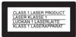
This appliance is classified as
a CLASS 1 LASER product.
The CLASS 1 LASER
PRODUCT MARKING is
located on the rear exterior.
Unleaded solder
Boards requiring use of unleaded solder are printed with the lead-free mark (LF) indicating the solder contains no lead.
(Caution: Some printed circuit boards may not come printed with the lead free mark due to their particular size.)

: LEAD FREE MARK
Unleaded solder has the following characteristics.
- Unleaded solder melts at a temperature about 40^ higher than ordinary solder.
Ordinary soldering irons can be used but the iron tip has to be applied to the solder joint for a slightly longer time.
Soldering irons using a temperature regulator should be set to about 350^ C.
Caution: The printed pattern (copper foil) may peel away if the heated tip is applied for too long, so be careful!
- Strong viscosity
Unleaded solder is more viscous (sticky, less prone to flow) than ordinary solder so use caution not to let solder bridges occur such as on IC pins, etc.
• Usable with ordinary solder
It is best to use only unleaded solder but unleaded solder may also be added to ordinary solder.
SAFETY-RELATED COMPONENT WARNING!!
COMPONENTS IDENTIFIED BY MARK △ OR DOTTED LINE WITH MARK △ ON THE SCHEMATIC DIAGRAMS AND IN THE PARTS LIST ARE CRITICAL TO SAFE OPERATION. REPLACE THESE COMPONENTS WITH SONY PARTS WHOSE PART NUMBERS APPEAR AS SHOWN IN THIS MANUAL OR IN SUPPLEMENTS PUBLISHED BY SONY.
TABLE OF CONTENTS
Precautions
1 Safety Precautions 5
2 Servicing Precautions 7
3 ESD Precautions 8
4 Handling the Optical Pick-up 9
5 Pick-up Disassembly and Reassembly 10
1. General
Getting Started.... 1-1
Basic Operations.... 1-6
Advanced Hookups 1-13
DVD Settings and Adjustments 1-14
DVD Additional Operations 1-17
VCR Additional Operations 1-22
Additional Information 1-26
2. Disassembly and Reassembly
2-1 Cabinet and PCB 2-1
2-1-1 Cabinet Top Removal 2-1
2-1-2 Bottom Cover Removal 2-1
2-1-3 Ass'y Front Panel Removal 2-1
2-1-4 Function PCB Removal 2-1
2-1-5 Chassis Removal 2-2
2-1-6 VCR Main PCB Removal 2-2
2-2 Circuit Board Locations 2-3
2-3 VCR Deck Parts Locations 2-4
2-3-1 Top View 2-4
2-3-2 Bottom View 2-6
2-4 VCR DECK 2-7
2-4-1 Holder FL Cassette Ass'y Removal 2-7
2-4-2 Lever FL Door Removal 2-7
2-4-3 Slider FL Drive, Gear FL Cam Removal 2-8
2-4-4 Lever FL Arm Ass'y Removal 2-8
2-4-5 Gear Worm Wheel Removal 2-9
2-4-6 Cable Flat Removal 2-9
2-4-7 Motor Loading Ass'y Removal 2-10
2-4-8 Bracket Gear, Gear Joint 2, 1 Removal 2-10
2-4-9 Gear Loading Drive, Slider Cam, Lever Load S, T Ass'y Removal 2-11
2-4-10Gear Loading Drive, Slider Cam, Lever Load S, T Ass'y Assembly 2-11
2-4-11 Lever Pinch Drive, Lever Tension Drive Removal 2-12
2-4-12 Lever Tension Ass'y, Band Brake Ass'y Removal 2-12
2-4-13 Lever Brake S, T Ass'y Removal 2-13
2-4-14Gear Idle Ass'y Removal 2-13
2-4-15Disk S, T Reel Removal 2-14
2-4-16Holder Clutch Ass'y Removal 2-14
2-4-17 Lever Up Down Ass'y, Gear Center Ass'y Removal ..... 2-15
2-4-18Guide Cassette Door Removal 2-15
2-4-19 Lever Unit Pinch Ass'y, Plate Joint, Spring Pinch Drive Removal 2-16
2-4-20 Lever #9 Guide Ass'y Removal 2-16
2-4-21FE Head Removal 2-17
2-4-22ACE Head Removal 2-17
2-4-23Slider S, T Ass'y Removal 2-18
2-4-24Plate Ground Deck, Cylinder Ass'y Removal 2-18
2-4-25Belt Pulley Removal 2-19
2-4-26Motor Capstan Ass'y Removal 2-19
2-4-27Post #8 Guide Ass'y Removal 2-20
2-4-28Level Head Cleaner Ass'y Removal (Optional) 2-20
2-4-29How to Eject the Cassette Tape 2-20
2-5 The Table of Cleaning, Lubrication and Replacement Time about Principal Parts 2-21
2-6 DVD Deck 2-22
2-6-1 Tray Disc Removal 2-22
2-6-2 Ass'y P/U Deck Removal 2-23
2-6-3 Housing Ass'y Removal 2-24
2-6-4 Sub Chassis Removal 2-25
2-6-5 Ass'y Brkt Deck Removal 2-26
3. Block Diagram 3-1
4. PCB Diagrams
4-1 VCR Main 4-3
4-2 DVD Main 4-7
4-3 S.M.P.S. 4-11
4-4 Function 4-13
4-5 Dial-Timer (SLV-D950B/D950E/D950GI/D910AZ Only)…… 4-13
5. Schematic Diagrams
◆ Block Identification of Main PCB 5-3
5-1 S.M.P.S. 5-5
5-2 Power Drive 5-7
5-3 OSD/VPS/PDS 5-9
5-4 A2/NICAM 5-11
5-5 Audio/Video 5-13
5-6 Hi-Fi 5-15
5-7 Input-Output 5-17
5-8 TM 5-19
5-9 Syscon 5-21
5-10 Logic/Function 5-23
5-11 SECAM (SLV-D950B/D910B/D910R Only) 5-25
5-12 DVD Main-Micom/AV Decoder 5-27
5-13 DVD Servo 5-29
5-14 DVD Audio/Video 5-31
6. Alignment and Adjustments
6-1 VCR Adjustment 6-1
6-1-1 Reference 6-1
6-1-2 Head Switching Point Adjustment 6-3
6-1-3 NVRAM Option Setting 6-3
6-2 DVD Adjustment 6-4
6-2-1 Location of Test Point 6-4
6-2-2 Skew Adjustment 6-5
6-3 VCR Mechanical Adjustment 6-7
6-3-1 Tape Transport System and Adjustment Locations 6-7
6-3-2 Tape Transport System Adjustment 6-8
6-3-3 Reel Torque 6-13
7. Troubleshooting 7-1
8. Repair Parts List
8-1 Exploded Views 8-2
8-1-1 Cabinet Assembly 8-2
8-1-2 VCR Mechanical Parts (Top Side) 8-4
8-1-3 VCR Mechanical Parts (Bottom Side) 8-5
8-1-4 DVD Mechanical Parts 8-6
8-2 Electrical Parts List 8-7
1 SAFETY PRECAUTIONS
1) Before returning an instrument to the customer, always make a safety check of the entire instrument, including, but not limited to, the following items:
(1) Be sure that no built-in protective devices are defective or have been defeated during servicing.
(1) Protective shields are provided to protect both the technician and the customer. Correctly replace all missing protective shields, including any removed for servicing convenience.
(2) When reinstalling the chassis and/or other assembly in the cabinet, be sure to put back in place all protective devices, including, but not limited to, nonmetallic control knobs, insulating fish papers, adjustment and compartment covers/shields, and isolation resistor/capacitor networks. Do not operate this instrument or permit it to be operated without all protective devices correctly installed and functioning.
(2) Be sure that there are no cabinet openings through which adults or children might be able to insert their fingers and contact a hazardous voltage. Such openings include, but are not limited to, excessively wide cabinet ventilation slots, and an improperly fitted and/or incorrectly secured cabinet back cover.
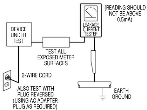
(3) Leakage Current Hot Check-With the instrument completely reassembled, plug the AC line cord directly into a 120V AC outlet. (Do not use an isolation transformer during this test.) Use a leakage current tester or a metering system that complies with American National Standards institute (ANSI) C101.1 Leakage Current for Appliances and Underwriters Laboratories (UL) 1270 (40.7). With the instrument's AC switch first in the ON position and then in the OFF position, measure from a known earth ground (metal water pipe, conduit, etc.) to all exposed metal parts of the instrument (antennas, handle brackets, metal cabinets, screwheads, metallic overlays, control shafts, etc.), especially any exposed metal parts that offer an electrical return path to the chassis.
Any current measured must not exceed 0.5mA. Reverse the instrument power cord plug in the outlet and repeat the test. See Fig. 1.
Any measurements not within the limits specified herein indicate a potential shock hazard that must be eliminated before returning the instrument to the customer.
flowchart
graph TD
    A["DEVICE UNDER TEST"] --> B["TEST ALL EXPOSED METER SURFACES"]
    B --> C["LEAKAGE CURRENT TESTER"]
    C --> D["2-WIRE CORD"]
    D --> E["ALSO TEST WITH PLUG REVERSED (USING AC ADAPTER PLUG AS REQUIRED)"]
    C --> F["(READING SHOULD NOT BE ABOVE 0.5mA)"]
    G["EARTH GROUND"] --> H["Ground"]
Fig. 1 AC Leakage Test
(4) Insulation Resistance Test Cold Check-(1) Unplug the power supply cord and connect a jumper wire between the two prongs of the plug. (2) Turn on the power switch of the instrument. (3) Measure the resistance with an ohmmeter between the jumpered AC plug and all exposed metallic cabinet parts on the instrument, such as screwheads, antenna, control shafts, handle brackets, etc. When an exposed metallic part has a return path to the chassis, the reading should be between 1 and 5.2 megohm. When there is no return path to the chassis, the reading must be infinite. If the reading is not within the limits specified, there is the possibility of a shock hazard, and the instrument must be repaired and rechecked before it is returned to the customer. See Fig. 2.
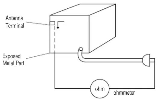
Fig. 2 Insulation Resistance Test
2) Read and comply with all caution and safety related notes on or inside the cabinet, or on the chassis.
3) Design Alteration Warning-Do not alter or add to the mechanical or electrical design of this instrument. Design alterations and additions, including but not limited to, circuit modifications and the addition of items such as auxiliary audio output connections, might alter the safety characteristics of this instrument and create a hazard to the user. Any design alterations or additions will make you, the servicer, responsible for personal injury or property damage resulting therefrom.
4) Observe original lead dress. Take extra care to assure correct lead dress in the following areas:
(1) near sharp edges, (2) near thermally hot parts (be sure that leads and components do not touch thermally hot parts), (3) the AC supply, (4) high voltage, and (5) antenna wiring. Always inspect in all areas for pinched, out-of-place, or frayed wiring, Do not change spacing between a component and the printed-circuit board. Check the AC power cord for damage.
5) Components, parts, and/or wiring that appear to have overheated or that are otherwise damaged should be replaced with components, parts and/or wiring that meet original specifications.
Additionally, determine the cause of overheating and/or damage and, if necessary, take corrective action to remove any potential safety hazard.
6) Product Safety Notice-Some electrical and mechanical parts have special safety-related characteristics which are often not evident from visual inspection, nor can the protection they give necessarily be obtained by replacing them with components rated for higher voltage, wattage, etc. Parts that have special safety characteristics are identified by shading, an ( ) or a ( ) on schematics and parts lists. Use of a substitute replacement that does not have the same safety characteristics as the recommended replacement part might create shock, fire and/or other hazards. Product safety is under review continuously and new instructions are issued whenever appropriate.
CAUTION: Before servicing units covered by this service manual and its supplements, read and follow the Safety Precautions section of this manual.
Note: If unforeseen circumstances create conflict between the following servicing precautions and any of the safety precautions, always follow the safety precautions. Remember: Safety First.
2-1 General Servicing Precautions
(1) a. Always unplug the instrument's AC power cord from the AC power source before (1) re-moving or reinstalling any component, circuit board, module or any other instrument assembly, (2) disconnecting any instrument electrical plug or other electrical connection, (3) connecting a test substitute in parallel with an electrolytic capacitor in the instrument.
b. Do not defeat any plug/socket B+ voltage interlocks with which instruments covered by this service manual might be equipped.
c. Do not apply AC power to this instrument and/or any of its electrical assemblies unless all solid-state device heat sinks are correctly installed.
d. Always connect a test instrument's ground lead to the instrument chassis ground before connecting the test instrument positive lead. Always remove the test instrument ground lead last.
Note: Refer to the Safety Precautions section ground lead last.
(2) The service precautions are indicated or printed on the cabinet, chassis or components. When servicing, follow the printed or indicated service precautions and service materials.
(3) The components used in the unit have a specified flame resistance and dielectric strength.
When replacing components, use components which have the same ratings. Components identified by shading, by (A) or by (A) in the circuit diagram are important for safety or for the characteristics of the unit. Always replace them with the exact replacement components.
(4) An insulation tube or tape is sometimes used and some components are raised above the printed wiring board for safety. The internal wiring is sometimes clamped to prevent contact with heating components. Install such elements as they were.
(5) After servicing, always check that the removed screws, components, and wiring have been installed correctly and that the portion around the serviced part has not been damaged and so on. Further, check the insulation between the blades of the attachment plug and accessible conductive parts.
2-2 Insulation Checking Procedure
Disconnect the attachment plug from the AC outlet and turn the power ON. Connect the insulation resistance meter (500V) to the blades of the attachment plug. The insulation resistance between each blade of the attachment plug and accessible conductive parts (see note) should be more than 1 Megohm.
Note: Accessible conductive parts include metal panels, input terminals, earphone jacks, etc.
Electrostatically Sensitive Devices (ESD)
Some semiconductor (solid state) devices can be damaged easily by static electricity.
Such components commonly are called Electrostatically Sensitive Devices (ESD). Examples of typical ESD devices are integrated circuits and some field-effect transistors and semiconductor chip components. The following techniques should be used to help reduce the incidence of component damage caused by static electricity.
(1) Immediately before handling any semiconductor component or semiconductor-equipped assembly, drain off any electrostatic charge on your body by touching a known earth ground. Alternatively, obtain and wear a commercially available discharging wrist strap device, which should be removed for potential shock reasons prior to applying power to the unit under test.
(2) After removing an electrical assembly equipped with ESD devices, place the assembly on a conductive surface such as aluminum foil, to prevent electrostatic charge buildup or exposure of the assembly.
(3) Use only a grounded-tip soldering iron to solder or unsolder ESD devices.
(4) Use only an anti-static solder removal devices. Some solder removal devices not classified as “anti-static” can generate electrical charges sufficient to damage ESD devices.
(5) Do not use freon-propelled chemicals. These can generate electrical charges sufficient to damage ESD devices.
(6) Do not remove a replacement ESD device from its protective package until immediately before your are ready to install it. (Most replacement ESD devices are packaged with leads electrically shorted together by conductive foam, aluminum foil or comparable conductive materials).
(7) Immediately before removing the protective materials from the leads of a replacement ESD device, touch the protective material to the chassis or circuit assembly into which the device will be installed.
CAUTION: Be sure no power is applied to the chassis or circuit, and observe all other safety precautions.
(8) Minimize bodily motions when handling unpackaged replacement ESD devices. (Otherwise harmless motion such as the brushing together of your clothes fabric or the lifting of your foot from a carpeted floor can generate static electricity sufficient to damage an ESD device).
The laser diode in the optical pick up may suffer electrostatic breakdown because of potential static electricity from clothing and your body.
The following method is recommended.
(1) Place a conductive sheet on the work bench (The black sheet used for wrapping repair parts.)
(2) Place the set on the conductive sheet so that the chassis is grounded to the sheet.
(3) Place your hands on the conductive sheet(This gives them the same ground as the sheet.)
(4) Remove the optical pick up block
(5) Perform work on top of the conductive sheet. Be careful not to let your clothes or any other static sources to touch the unit.
◆ Be sure to put on a wrist strap grounded to the sheet.
- Be sure to lay a conductive sheet made of copper etc. Which is grounded to the table.
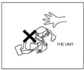
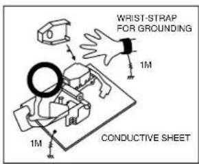
Fig.3
(6) Short the short terminal on the PCB, which is inside the Pick-Up ASS'Y, before replacing the Pick-Up. (The short terminal is shorted when the Pick-Up Ass'y is being lifted or moved.)
(7) After replacing the Pick-up, open the short terminal on the PCB.
5-1 Disassembly
1) Remove the power cord.
2) Disassemble the Deck-Assy.
3) Make solder land 2 points short on Pick-up. (See Fig. 4)
4) Disassembly the Pick-up.
Note: If the assembly and disassembly are not done in correct sequence, the Pick-up may be damaged.
5-2 Assembly
1) Replace the Pick-up.
2) Remove the soldering 2 points on Pick-up.
3) Reassemble the Deck-Assy.
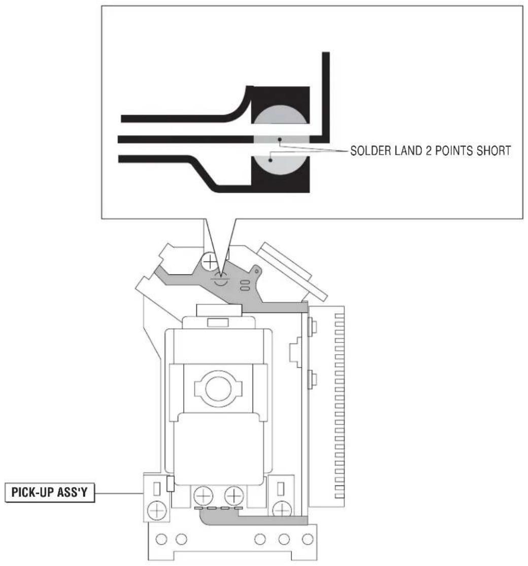
Fig. 4
1. GENERAL
This section is extracted from SLV-D910B/D950B instruction manual. (3-084-916-E2)
Getting Started
Step 1 : Unpacking
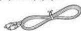
Check that you have received the following items with the DVD-VCR:
• R emote commander • PERITEL cable
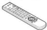
• R 6 ( size AA) batteries • Audio cord

(pinplug ×2 ↔ pinplug ×2)
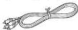
• A erial cable • Video cord
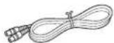
(pinplug ×1 ↔ pinplug ×1)
Check your model name
The instructions in this manual are for the 2 models: SLV-D950B and SLV-D910B. Check your model name by looking at the rear panel of your DVD VCR. SLV-D950B is the model used for illustration purposes. Any difference in operation is clearly indicated in the text, for example, "SLV-D950B only".
8 | Unpacking
Controlling other TVs with the remote commander
The remote commander is preprogrammed to control non-Sony TVs. If your TV is listed in the following table, set the appropriate manufacturer's code number.
1 Set TV / DVD-VIDEO at the top of the remote commander to TV.
2 Hold down 1/1, and enter your TV's code number using the number buttons. Then release 1/1.
Now you can use the I/ ^b , VOL +/-, PROG +/-, MUTING +, TV/VIDEO, 0-9 and -/- + buttons to control your TV. You can also use the buttons marked with a dot (*) to control a Sony TV. To control the DVD-VCR, reset TV/ DVD-VIDEO to DVD-VIDEO.
- for Sony TV only
Code numbers of controllable TVs
If more than one code number is listed, try entering them one at a time until you find the one that works with your TV.
| Manufacturer | Code number |
| Sunny | 01, 02 |
| Akai | 68 |
| Ferguson | 52 |
| Grundig | 10.11 |
| Hitachi | 24 |
| JVC | 33 |
| Loewe | 45 |
| Mivar | 09.70 |
| NEC | 66 |
| Nokia | 15, 16, 69 |
| Manufacturer | Code number |
| Parasomic | 17, 49 |
| Philips | 06, 07, 08 |
| Saba | 12, 13 |
| Samsung | 22, 23 |
| Sanyo | 25 |
| Sharp | 29 |
| Telefunken | 36 |
| Thomson | 43 |
| Toshitsu | 38 |
Notes
- If you enter a new code number, the code number previously entered will be erased.
- If the TV uses a different remote control system from the one programmed to work with the DVD-VCR, you cannot control your TV with the remote commander.
- When you replace the batteries of the remote commander, the code number may change. Set the appropriate code number every time you replace the batteries.
Step 2 : Setting up the remote commander
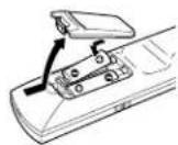
Inserting the batteries
Insert two size AA (R6) batteries by matching the + and - on the batteries to the diagram inside the battery compartment.
Insert the negative (-) end first, then push in and down until the positive (+) end clicks into position.
Using the remote commander
You can use this remote commander to operate this DVD-VCR and a Sony TV. Buttons on the remote commander marked with a dot (*) can be used to operate your Sony TV.
If the TV does not have the symbol near the remote sensor, this remote commander will not operate the TV.
Getting Started
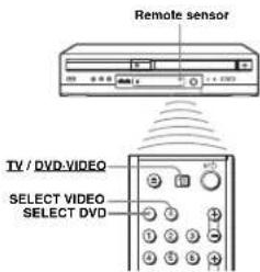
| To operate | Set TV / DVD-VIDEO to |
| the DVD player DVD-VIDEO _ then press SELECT DVD and point at the remote sensor at the DVD-VCR | |
| the VCR DVD-VIDEO _ then press SELECT VIDEO and point at the remote sensor at the DVD-VCR | |
| your TV TV _ and point at the remote sensor at your TV | |
Notes
- With normal use, the batteries should last about three to six months.
- If you do not use the remote commander for an extended period of time, remove the batteries to avoid possible damage from battery leakage.
• D e not use a new battery with an old one.
• Do not use different types of barteries. - Do not leave the remote commander in an extremely hot or humid place.
- Do not drop any foreign object into the remote casing, particularly when replacing the batteries.
- Do not expose the remote sensor to direct light from the sun or lighting apparatus. Doing so may cause a malfunction.
continued
Setting up the remote commander
9
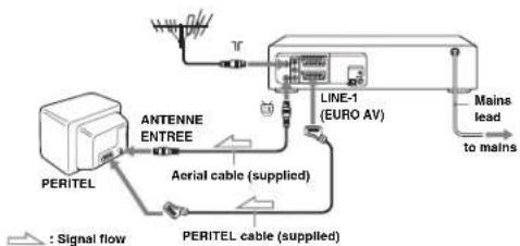
Step 3 : Connecting the DVD-VCR
Note that "Advanced Hookups" (page 59) explains additional hookup methods that will optimize the picture and sound for a true "hometheatre" experience.
flowchart
graph TD
    A["PERITEL"] --> B["ANTENNE ENTREE"]
    B --> C["Aerial cable (supplied)"]
    C --> D["PERITEL cable (supplied)"]
    D --> E["LINE-1 (EURO AV)"]
    E --> F["Mains lead to mains"]
    G["Wireless Signal"] --> H["T"]
    H --> I["Antenna"]
Getting Started
| 1 | Disconnect the aerial cable from your TV and connect it to on the rear panel of the DVD-VCR. |
| 2 | Connect the DVD-VCR and the aerial input of your TV using the supplied aerial cable. |
| 3 | Connect LINE-1 (EURO AV) on the DVD-VCR and the PBRITEL connector on the TV with the supplied PERITEL cable.This connection improves picture and |
4 Connect the mains lead to the mains.
continued
Connecting the DVD-VCR
Additional connection
To a satellite or digital tuner with Line Through
Using the Line Through function, you can watch programmes from a satellite or digital tuner connected to this DVD-VCR on the TV even when the DVD-VCR is turned off. When you turn on the satellite or digital tuner, this DVD-VCR automatically sends the signal from the satellite or digital tuner to the TV without turning itself on.
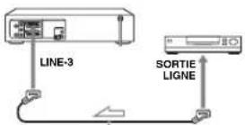
PERITEL cable (not supplied)

1 Connect the satellite or digital tuner to the LINE-3 connector as shown above.
2 Turn off the DVD VCR.
To watch a programme, turn on the satellite or digital tuner and the TV.
Notes
- This function may not work with some types of satellite or digital tuners.
- When the DVD-VCR is turned off, set the TV to the video channel
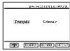
Press ♦/♦ to select your country, then press ENTER.
The DVD-VCR starts searching for all of the receivable channels and presets them (in the appropriate order for your local area).
If you want to change the order of the channels or disable unwanted programme positions, see "Changing/disabling programme positions" on
After the search is complete, the current time appears for any stations that transmit a time signal. If the time does not appear, set the clock manually. See "Setting the clock" on page 16.
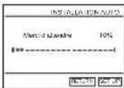
To cancel the Auto Set Up function
Press SET UP.
Tip
- If you want to change the language for the on-screen display from the one preset in the Auto Set Up function, see page 15.
Notes
- Whenever you operate the Auto Set Up function, some of the settings (ShowView, tumor, etc.) will be reset. If this happens, you have to set them again.
- Auto preset starts automatically only when you plug in the mains lead for the first time after you purchase the DVD-VCR.
- If you want to use the Auto Set Up function again, select "Installation" in the "OPTION" menu, then press ♦/♦ to select "Installation Auto", then repeat step 3.
- Auto preset can be performed by pressing ■ on the unit continuously for 5 seconds or more during power off with no tape inserted.
Step 4 : Setting up the DVD-VCR with the Auto Set Up function
Before using the DVD-VCR for the first time, set up the DVD-VCR using the Auto Set Up function. With this function, you can set TV channels, guide channels for the ShowView system *, and DVD-VCR clock automatically.
• SLY-D950B only
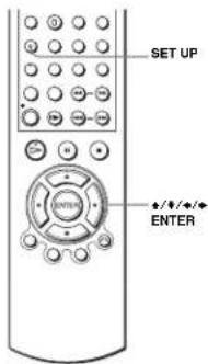
1
Turn on your TV and set it to the video channel.
2
Connect the mains lead to the mains.
The DVD-VCR automatically turns on and the "SELECTION DU PAYS" menu appears.
continued
Setting up the DVD-VCR with the Auto Set Up function
13
Step 5 : Selecting a language
If you prefer an on-screen language other than French, use the on-screen display to select another language.
Before you start...
• T ur n on the DVD-VCR and your TV.
- T is control the DVD-VCR, set TV DVD-VIDEO to DVD-VIDEO on the remote (page 9).
- S et your TV to the video channel so that the signal from the player appears on the TV screen.
- If the DVD player is in play mode, you cannot display the setup menu. Stop the DVD playback.
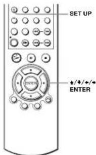
1

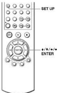
Press SET UP, then press ♦/♦ to select (OPTION) and press ENTER.
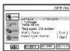

2

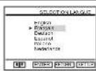
Press ♦/♦ to select "Langue", then press ENTER. The "SELECTION LANGUE" menu appears.
3

Press ♦/♦ to select the desired language, then press ENTER.
4

Press SET UP to exit the menu.
Selecting a language
15
Step 6 : Setting the clock
You must set the time and date on the DVD-VCR to use the timer features properly.
The Auto Clock Set function works only if a station in your area is broadcasting a time signal.
Before you start...
• Turn on the DVD-VCR and your TV.
• T o control the DVD-VCR, set TV
DVD-VIDEO to DVD-VIDEO on the
remote (page 9)
- Set your TV to the video channel so that the signal from the player appears on the TV screen.
- If the DVD player is in play mode, you cannot display the setup menu. Stop the DVD playback.
1

Press SET UP, then press ♦/♦ to select (OPTION) and press ENTER.

2

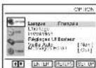
Press ♦/♦ to select "L'horloge", then press ENTER.
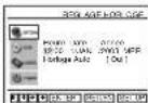
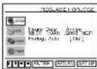
The "REGLAGE HORI.OGE" menu appears.
3

Press ♦/♦ to set the hour.
16
Setting the clock
Step 7 : Presetting channels
If some channels could not be preset using the Auto Set Up function, you can preset them manually.
Before you start...
• Turn on the DVD-VCR and your TV.
• T o control the DVD-VCR, set TV DVD-VIDEO to DVD-VIDEO on the remote (page 9).
- Set your TV to the video channel so that the signal from the player appears on the TV screen.
- If the DVD player is in play mode, you cannot display the setup menu. Stop the DVD playback.
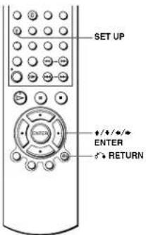
1

Press SET UP, then press ♦/♦ to select (OPTION) and press ENTER.

2

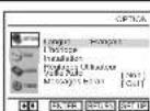
Press ♦/♦ to select "Installation", then press ENTER.
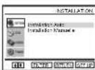
The "INSTALLATION" menu appears.
18
Presetting channels
4

Press to select the minutes and set the minutes by pressing / .
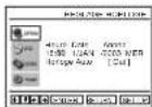
5

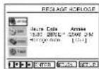
Set the day, month, and year in sequence by pressing ♦ to select the item to be set, and press ♦/♦ to select the digits, then press ♦. The day of the week is set automatically.
6

Press ♦/♦ to select "Oui" for the setting of the Auto Clock Set function.
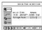
The DVD-VCR automatically sets the clock according to the time signal broadcast between the channels PR 1 to PR 5.
If you do not need the Auto Clock Set function, select "Non".
7

The Ground Truth image displays a single, solid horizontal line. According to Rule 2 (UNDERSCORE & LINE RULES), this is a stylistic or background line, not a placeholder underscore. Therefore, the OCR result must ignore it. The provided OCR content is "____", which consists of four underscores. This is an incorrect interpretation of the line as a placeholder, violating the rule that stylistic lines must be ignored. The OCR has hallucinated text (underscores) where none should exist. Hence, the result is inconsistent with the Ground Truth.
8

Press SET UP to exit the menu.
Tips
- If you set "Horloge Auto" to "Oui", the Auto Clock Set function is activated whenever the DVD VCR is turned off. The time is adjusted automatically by making reference to the time signal from the station.
- To change the digits while setting, press to return to the item to be changed, and select the digits by pressing / .
Note
• The clock display appears when VIDEO mode is selected with no tape inserted or when the DVD-VCR is turned off.
Setting the clock
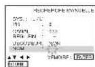
17
3

Press ♦/♦ to select "Installation Manuelle", then press ENTER.
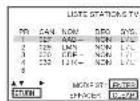
4

Press ♠/♦ to select the row which you want to preset, then press ♦.
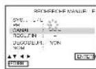
5

Press ♦/♦ to select "SYS." if necessary.
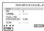
6

Press ♦/♦ to set "L/L." or "B/G" if necessary. • T o receive broadcast in France, select "L/L".
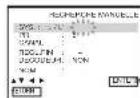
7

Press ♦/♦ to select "CANAL", then press ♦/♦ repeatedly until the channel you want is displayed.
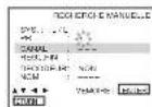
8

Press ♦/♦ to select "NOM", then press ➔.
continued
Presetting channels
19
4
6
7
8
9

Enter the station name.
1 Press ♦/♦ to select a character. Each time you press ♦, the character
changes as shown below. A → B → ... → Z → 0 → 1 → ... → 9 → A
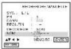
2 Press → to set the next character.
The next space flashes.
To correct a character, press ◆/◆ until the character you want to correct flashes, then reset it.
You can set up to 4 characters for the station name.
10

Press ENTER to confirm the station name.
11

Press o RETURN, then press SET UP to exit the menu.

If the picture is not clear
If the picture is not clear, you may use the Manual Fine Tuning (REGL.FIN)
function. After step 7, press ♦/♦ to select "REGL.FIN". Press ♦/♦ to get a clear picture. Then press ENTER.
Tips
- To set the programme position for the decoder, see "Setting the Canal Plus decoder" on
page 27.
- The DVD-VCR must receive channel information for station names to appear automatically.
Note
- When adjusting REGL.FIN, the menu may become difficult to read due to interference from the picture being received.
20
Presetting channels
3

Press ♦/♦ to select "Installation Manuelle", then press ENTER.
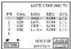
4

Press / to select the row containing the programme position you want to change. To display other pages for programme positions 6 to 80, press / repeatedly.
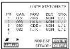
5

Press ENTER, then press ♦/♦ to move to the desired programme position.
6

Press ENTER to confirm the setting.
To change the programme position of another station, repeat steps 4 through 6.
7

Press ⬆ RETURN, then press SET UP to exit the menu.
22
Presetting channels
Changing/disabling programme positions
After setting the channels, you can change the programme positions as you like. If any programme positions are unused or contain unwanted channels, you can disable them.
You can also change the station names. If the station names are not displayed, you can enter them manually.
Changing programme
positions
Before you start...
• Turn on the DVD-VCR and your TV
• T o control the DVD-VCR, set TV DVD-VIDEO to DVD-VIDEO on the remote (page 9).
- S et your TV to the video channel so that the signal from the player appears on the TV screen.
• If the DVD player is in play mode, you cannot display the setup menu. Stop the DVD playback.
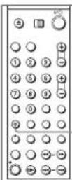
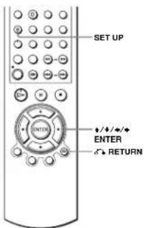
-SET UP

RETURN
Getting Started
1

Press SET UP, then press ♦/♦ to select (OPTION) and press ENTER.
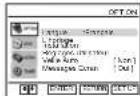

2

Press ♦/♦ to select "Installation", then press ENTER.
The "INSTALLATION" menu appears.
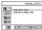
continued
Presetting channels
21
Disabling unwanted programme positions
After presetting channels, you can disable unused programme positions. The disabled positions will be skipped later when you press the PROG +/- buttons.
Before you start...
• T ur n on the DVD-VCR and your TV.
• T o control the DVD-VCR. set TV DVD-VIDEO to DVD-VIDEO on the remote (page 9).
- S et your TV to the video channel so that the signal from the player appears on the TV screen.
- If the DVD player is in play mode, you cannot display the setup menu. Stop the DVD playback.
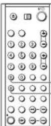
CLEAR
SET UP
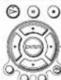
+/+/+/+ ENTER RETURN
Getting Started
1

Press SET UP, then press ↑/↓ to select (OPTION) and press ENTER.

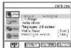

2

Press ♦/♦ to select "Installation", then press ENTER.
The "INSTALLATION" menu appears.
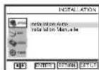
continued
Presetting channels
23
3

Press ♦/♦ to select "Installation Manuelle", then press ENTER.
| UNIT KONING TO | ||||
| PIN | CAN | NOM | DEC | SYS |
| 1 | OZ | PAB | NON | L2E |
| 2 | PN | PAN | MIN | L11 |
| 3 | GS | GDS - | NON | L11 |
| 4 | GD | L18 | MIN | L11 |
| 5 | ||||
4

Press ♦/♦ to select the row which you want to disable. To display other pages for programme positions 6 to 80, press ♦/♦ repeatedly.
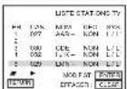
| LISTE STATIONS TV | ||||
| FR | CAN | NO4 | DEC | SVC |
| 1 | 027 | AAD - | NON | L L' |
| 2 | 029 | LON | NON | L L' |
| 3 | 031 | L30 - | MIN | L L' |
| 4 | 032 | LJK - | NON | L L' |
| 5 | ||||
5

Press CLEAR. The selected row will be cleared as shown on the right.
| PR | CAN | NOM | DEC | CVS |
| 1 | U2F | PAB | NOM | L1 L' |
| 2 | 690 | CDC- | NON | L1 L' |
| 4 | 682 | IJK- | NON | L1 L' |
| 5 |
6
Repeat steps 4 and 5 for any other programme positions you want to disable.
7

Press ⬆ RETURN, then press SET UP to exit the menu.

Note
- B: e sure to select the programme position you want to disable correctly. If you disable a programme position by mistake, you need to reset that channel manually.
24
Presetting channels
4

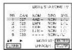
Press ♦/♦ to select the row which you want to change or enter the station name, then press ♦. To display other pages for programme positions 6 to 80, press ♦/♦ repeatedly.
| RECHNOIS MANUELLE | |
| SVC | 1.11 |
| PIL | 5 |
| LONG | 100 |
| FOM PIN | — |
| DECOOLIF | NON |
| NOM | — |
5

Press ↑/↓ to select "NOM", then press ♦.
| SYS. L'L | |
| PH. | h |
| CASA : 100 | |
| FECLIN | - |
| DECOOCH : NO | |
| MRO | |
6

Enter the station name.
| RECHNO 10 MANUELLE | |
| NYA | 1.11 |
| PR | 5 |
| CANAL | 003 |
| PEULHN | |
| ECCOCULF | NON |
| NOSI | -0 |
1 Press / to select a character. Each time you press . the character changes as shown below. A → B → ... → Z → 0 → 1 → ... → 9 → A
2 Press to set the next character.
The next space flashes.
To correct a character, press ♦/♦ until the character you want to correct flashes, then reset it.
You can set up to 4 characters for the station name.
7

Press ENTER to confirm the new name.
8

Press ⬇ RETURN, then press SET UP to exit the menu.
26
Presetting channels
Changing the station names
You can change or enter the station names (up to 4 characters). The DVD-VCR must receive channel information for station names to appear automatically.
Before you start...
• Turn on the DVD-VCR and your TV.
• T o control the DVD-VCR, set TV DVD-VIDEO to DVD-VIDEO on the remote (page 9).
- S et your TV to the video channel so that the signal from the player appears on the TV screen.
- If the DVD player is in play mode, you cannot display the setup menu. Stop the DVD playback.
Getting Started
1

Press SET UP, then press ♦/♦ to select (OPTION) and press ENTER.

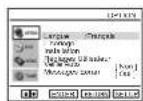

2

Press ♦/♦ to select "Installation", then press ENTER. The "INSTALLATION" menu appears.
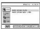
3

Press ♦/♦ to select "Installation Manuelle", then press ENTER.
continued
Preselling channels
25
Setting the Canal Plus decoder
You can watch or record Canal Plus programmes if you connect a decoder (not supplied) to the DVD VCR.
Connecting a decoder
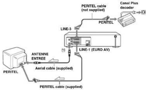
flowchart
graph TD
    A["PERITEL"] --> B["ANTENNE ENTREE"]
    B --> C["Aerial cable (supplied)"]
    C --> D["PERITEL cable (supplied)"]
    D --> E["PERITEL cable (not supplied)"]
    E --> F["Canal Plus decoder"]
    F --> G["LINE-1 (EURO AV)"]
    G --> H["LINE-3"]
    H --> I["PERITEL"]

: Signal flow
Getting Started
continued
Setting the Canal Plus decoder
27
Setting Canal Plus channels
To watch or record Canal Plus programmes, set your DVD-VCR to receive the channels using the on-screen display.
In order to set the channels correctly, be sure to follow all of the steps below.
Before you start...
• T u r n on the DVD-VCR and your TV.
• T o control the DVD-VCR, set TV DVD-VIDEO to DVD-VIDEO on the remote (page 9).
- Set your TV to the video channel so that the signal from the player appears on the TV screen.
- If the DVD player is in play mode, you cannot display the setup menu. Stop the DVD playback.
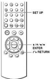
1

Press SET UP, then press ♦/♦ to select (OPTION) and press ENTER.
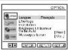

2

Press ↑/↓ to select "Installation", then press ENTER.
The "INSATLLATION" menu appears.
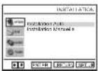
3

Press ♦/♦ to select "Installation Manuelle", then press ENTER.
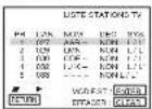
28
Selling the Canal Plus decoder
Notes
- To be a perimpose subtitles while watching Canal Plus programmes, make both decoder-VCR and VCR-TV connections using 21-pin PERITEL cables that are compatible with the RGB signals. You cannot record subtitles on the VCR.
- When you watch Canal Plus programmes through the RFL input of the TV, press TV/VIDEO so that the VCR indicator appears in the display window.
4

Press ♦/♦ to select the row which you want to set for the decoder, then press ♦.
To display positions 6 to 80, press ♦/♦ repeatedly.
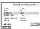
5

Press ♦/♦ to select "SYS" if necessary.
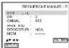
6

Press / to set "L/L" or "B/G" if necessary.
• T o receive broadcast in France, select "L/L".
- T o receive broadcast using the PAL system (for example, in Germany or Switzerland), select "B/G".
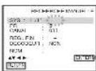
7

Press ♦/♦ to select "DECODEUR"
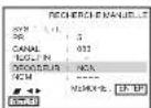
8

Press ➔ to set "DECODEUR" to "OUT", then press ENTER.
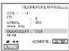
9

Press ⬇ RETURN, then press SET UP to exit the menu.
RETURN

continued
Selling the Canal Plus decoder
29
Basic Operations
Playing discs DVD VCD CD DATA-CD
Depending on the disc, some operations may be different or restricted. Refer to the operating instructions supplied with your disc.
Before you start...
- T ur n on the DVD-VCR and your TV
- S et your TV to the video channel so that the signal from the player appears on the TV screen.
- S c t /DVD-VIDEO to DVD-VIDEO, then press SELECT DVD to control the DVD player (page 9).
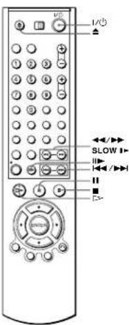
1
Press ▲ to open the disc tray and place a disc on the disc tray.
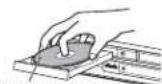
with the playback side facing down
Basic Operations
30
Setting the Canal Plus decoder
continued
Playing disc
31
2

Press =>.
The disc tray closes and the DVD player starts playback.
The display window shows the playback time. ^9 Depending on the disc, a menu may appear on the TV screen. For DVDs, see page 73. For VIDEO CDs, see page 93.
“- ----” appears when no disc is loaded.
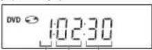
Hour Minute Second
Additional tasks
| To Press | |
| Stop play ■ | |
| Pause play + □ | |
| Resume play after pause □ or □= | |
| Advance by frame in pause mode □▶ | |
| Go to the next chapter, track, or scene in continuous play mode | ▶▶ on the remote |
| Go back to the previous chapter, track, or scene in continuous play mode | ◀◀ on the remote |
| Stop play and remove the disc ▲ |
* If you pause the DVD player for more than 5 minutes, the DVD player will automatically stop.
To Resume playback for the current disc (Resume Play)
The DVD player remembers the point where you stopped the disc even if the DVD player enters standby mode by pressing I/☐.
1 While playing a disc, press ■ to stop playback.
2 Press =>
The DVD player starts playback from the point where you stopped the disc in step 1.
Tip
• To begin playback from the tap of the disc, press ■ twice then press E=>.
32
Playing discs
To locate a point quickly by playing a disc in fast forward or fast reverse in continuous play mode (DVD, VIDEO CD and CD only)
Press ◀ or ▶▶
For DVD or VIDEO CD, each time you press the button, the playback speed changes as follows.
- 2 → FF1/FR1 → FF2/FR2 → FF3/FR3 → FF4/FR4 (DVD only) → FF5/FR5 (DVD only)
Release the button at the desired speed.
For CD, the searching speed does not change (FF2/FR2 play).
When you find the point you want, press
To watch slow motion in continuous play mode (DVD and VIDEO CD only)
Press Ⅱ, then press ▶▶ SLOW ▶. With each press, the playback speed changes cyclically as follows.
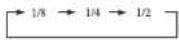
To resume normal playback, press
Tip
• To make a ke a video timer reservation during DVD playback, we recommend performing the operations under "Quick Timer Recording" (page 96).

Notes
- You can change the screen type using the "REGLAGE DE L'ECLAN" menu. (See "Screen Setup" on page 65.)
• D o not perform VIDEO playback while playing back a disc
- If you play a DVD or VIDEO CD that has scratches, the player may stop playback at the point of the scratch or skip to the next track.
- You can not change the MP3 or the Multi Session CD playback speed.
• V IDPO CD fast forward/reverse cannot be paused.
- During CD fast forward/reverse play, no sound is output.
Notes on playing DTS* sound tracks on a CD
- When playing DTS-encoded CDs, excessive noise will be heard from the analog stereo jacks. To avoid possible damage to the audio system, the consumer should take proper precautions when the analog stereo jacks of the DVD player are connected to an amplification system. To enjoy DTS Digital Surround™ playback, an external 5.1-channel decoder system must be connected to the digital jack of the DVD player.
- Set the sound to "STEREO" using the AUDIO button when you play DTS sound tracks on a CD (page 82).
- Do not play DTS sound tracks without first connecting the DVD player to an audio component having a built-in DTS decoder. The DVD player outputs the DTS signal via the DIGITAL AUDIO OUT (COAXIAL, or OPTICAL) jack even if "DTS" is set to "Non" in "Options Audio" mean (page 63), and may affect your ears or cause your speakers to be damaged.
continued
Playing discs
33
Notes on playing DVDs with a DTS sound track
- DTS audio signals are output only through the DIGITAL AUDIO OUT (COAXIAL or OPTICAL) jack.
- When you play a DVD with DTS sound tracks, set "DTS" to "Oui" in "Options Audio" menu (page 63).
- If you connect the player to audio equipment without a DTS decoder, do not set "DTS" to "Out" in "Options Audio" menu (page 63). A loud noise may come out from the speakers, affecting your ears or causing the speakers to be damaged.
* "DTS" and "DTS Digital Out" are trademarks of Digital Theater Systems, Inc.
Guide to the on-screen display DVD VCD CD DATA-CD
You can check disc information during playback.
The displayed contents differ according to the type of disc being played.
Press DISPLAY. The following information appears: type of disc, current title/track, chapter, counter position, voice language, subtitle language and surrnumal setting. Refer to "DVD Audio/Subtitle Language" on page 126 for the abbreviation of the language.
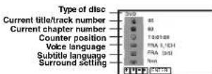
You can playback the desired title/track, chapter or counter position using this menu.
To playback the desired title/track or chapter
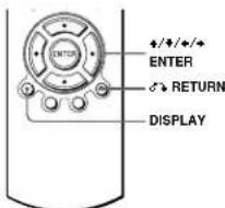
1 Press ♦/♦ to select the desired item.
2 Press +/→ to change the item.
3 Press ENTER to start playback.
4 Press DISPLAY or ⬆ RETURN to turn off the menu.
The title/track or chapter icon will appear on the DVD playback screen followed by the current title/track or chapter number and the counter position.

34
Playing discs
continued
Guide to the on-screen display
35
To playback from the desired title/track counter position
1 Press ♦/♦ to select the counter position icon
2 Enter the desired elapsed playing time of the current title/track using the number buttons.
3 Press ENTER to start playback
4 Press DISPLAY or a RETURN to turn off the menu.
Tip
- Y ou can change the counter position information (playing time or remaining time) using ♦/♦ (DVD and CD only).
DVD
Indication Counter Information
| T | • : • : • • | Elapsed playing time of the current title |
| T | • : • : • • | Remaining time of the current title |
| C | • : • : • • | Elapsed playing time of the current chapter |
| C- | • : • : • • | Remaining time of the current chapter |
CD
Indication Counter information
| T | • : • : • | Elapsed playing time of the current track |
| T- | • : • : • | Remaining time of the current track |
| D | • : • : • | Elapsed playing time of the disc |
| D | • : • : • | Remaining time of the disc |
Notes
• The display may not change as operated depending on the disc.
- T he display window continue indicating the playing time even when the counter position information on the on-screen display is being changed.
Playing a tape VHS
Before you start...
• Turn on the DVD-VCR and your TV.
- S et your TV to the video channel so that the signal from the player appears on the TV screen.
- S e_L /DVD-VIDEO to DVD-VIDEO, then press SELECT VIDEO to control the VCR (page 9).
Basic Operations
1
Insert a tape.
The VCR starts playing automatically if you insert a tape with its safety tab removed.
2
Press [=>
The display window shows the playback time.
When the tape reaches the end, it will rewind automatically.
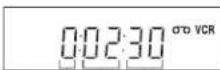
Hour Minute Second
continued
Playing a tape
37
36
Guide to the on-screen display
Additional tasks
| To Press | |
| Stop play | ■ |
| Pause play * | ■ |
| Resume play after pause | ■ or □- |
| Fast-forward the tape | ▶ during stop |
| Rewind the tape | ◀ during stop |
| Fject the tape | △ |
* If you pause the VCR for more than 5 minutes, the VCR will automatically resume play.
To play a recently watched scene
You can immediately rewind and playback the scene you want to watch again.
To skip playback
You can skip a scene that you do not want to watch (such as a commercial) and restart playback.
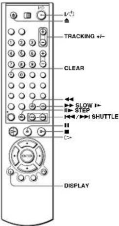
During playback, press ▶ STEP. The VCR skips the tape 30 seconds on the counter each time the button is pressed (up to four times) and playback is resumed.
To turn off the power while rewinding (Rewind Shut Off)
Press I/While the tape is rewinding. The power will turn off, but the tape will keep rewinding until it reaches the end.
To play / search at various speeds
| Playback options | Operation |
| View the picture during fast-forward or rewind | During fast-forward, hold down ➤. During rewind, hold down ←◀. |
| Play at high speed | During playback, briefly press ➤ or ←◀. The tape continues to play at 5 times normal speed.During playback, hold down ➤ or ←◀. The tape continues to play at 5 times normal speed. When you release the button, normal playback resumes. |
| Play in slow motion | During pause, press ➤ SLOW ➤. |
| Play frame by frame | During pause, press ➤ STTP. |
| Play at various speeds(Shuttle play) | During playback, press ➤ or ➤. You can change the playback speed as follows.REVIEW←→←→2←→-1←→SLOW←→ STILL←→SLOW←→ PLAY←→2←→CUE←→ |
^61 “REW” flashes in the display window.
^62 “FF” flashes in the display window.
To resume normal playback
Press ▷.
To set the colour system
If the playback picture has no colour, or streaks appear during palyback, set the "Syst. Couleur" option in the "REGLAGES UTILISATEUR" meant to conform to the system that the tape was recorded in (see page 110) (Normally set the option to "Auto").
To use the time counter
Press CLEAR at the point on the tape that you want to find later. The counter in the display window resets to "1:00:00".
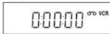
To display the counter on the TV screen, press DISPLAY during normal playback.
Tip
- A d j out the picture using the TRACKING +/- buttons if:
— Streaks appear while playing in slow motion.
- Bands appear at the top or bottom while pausing.
The picture shakes during pause.
Notes
- T apes recorded in the I.P mode on other VCRs can be played back on this VCR but the
picture quality cannot be guaranteed.
• The col in the results to (2013) whenever a tape is remiserted.
• I have to stop calling when it comes to a portion with no recording. - Depending on your TV, the following may occur while playing an NTSC-recorded tape:
- The picture becomes black and white.
— The picture snakes
- No picture appears on the TV screen.
- Black streaks appear horizontally on the TV screen.
- The colour density increases or decreases.
- When 10 hours have passed, the counter in the display window returns to "0:00:00" and the
count starts over again.
• T he sound is muted during playback at various speeds.
• The picture may show noise when playing at high speed in reverse. - While playing a tape, you can display the setup menu, but the remote commander's function switches to DVD automatically. Press SET UP to exit the menu.
• 5.1 op disc playback while playing back a video.
• T he picture returns to normal playback from slow motion in reverse in 30 seconds.
Basic Operations
38
Playing a tape
Playing a tape
39
Recording TV programmes VHS
Before you start...
• T ur n on the DVD-VCR and your TV.
- S witch the input selector on your TV so that the signal from the player appears on the TV screen.
- S +⊥ /DVD-VIDEO to DVD-VIDEO, then press SELECT VIDEO to control the VCR (page 9).
• T o record from a decoder, turn it on.
• Make sure the tape is longer than the total recording time.
![PROG +/- SP/LP TV/VIDEO INPUT SELECT ● REC ■ [+] DISPLAY](/content/2026/05/1017698/images/29b662c099cf5e32ec873b2ba67ad1da94698ed09e1e9799e4205626414d0234.jpg)
1
Insert a tape with its safety tab in place.
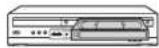
40
Recording TV programmes
In order to get an accurate remaining time indication, he sure "Sélect Cassette" in the "REGLAGE DE LA FONCTION VIDEO" menu is set according to the tape type you use (see page 105).
Maximum Recording Time
| Tape Length SP LP | ||
| E-180 3 hrs 6 hrs | ||
| E-240 4 hrs 5 hrs | ||
| E-260 4 hrs 20 mins | 8 hrs 40 mins | |
| E-300 5 hrs | 10 hrs | |
To watch another TV programme while recording
1 Press TV/VIDEO to display "TV" in the display window.
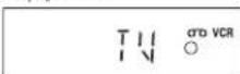
2 Select another channel on the TV.
To watch a DVD while recording
1 Press SELECT DVD to control the DVD player.
2 Press ▲ and place the disc on the disc tray.
3 Press D>
The disc tray closes and the DVD player starts playback. The TV screen will automatically change to the DVD playback screen.
To save a recording
To prevent accidental erasure, break off the safety tab as illustrated. To record on the tape again, cover the tab hole with adhesive tape.
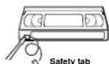
Tips
- To select a programme position, you can use the number buttons on the remote commander. For two-digit numbers, for example, press 2 and 3 to select "PR 23".
- If you connect additional equipment to a LINE connector or jack, you can select the input
signal using the INPUT SELECT or PROG 47 buttons. • T be DISPLAY information appears on the TV screen indicating information about the tape, but the information will not be recorded on the tape. - If you do not want to watch TV while recording, you can turn off the TV. When using a decoder, make sure to leave it on.
2
• PROCY TRACKING


- To record a normal channel, press PROG +/- until the programme position number you want appears in the display window.
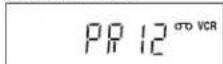
- To record from a decoder or other source connected to one or more of the LINE inputs, press INPUT SELECT until the connected line appears in the display window.
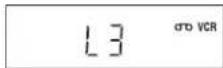
3

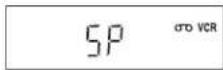
Press SP/LP to select the tape speed, SP or LP. LP (Long Play) provides recording time twice as long as SP. However, SP (Standard Play) produces better picture and audio quality.
4

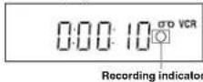
Press ● REC to start recording. The recording indicator lights up red in the display window.
To stop recording
Press ■.
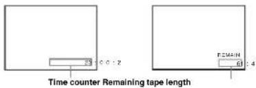
To check the remaining time
Press DISPLAY twice. With the display on, press DISPLAY again to check the remaining time.
continued
Recording TV programmes
41
Notes
- If a tape has portions recorded in both PAL (SECAM, MESECAM) and NTSC systems, the time counter reading will not be correct. This discrepancy is due to the difference between the counting cycles of the two video systems.
- You cannot watch a Canal Plus programme while recording another Canal Plus programme.
- When you insert a non-standard commercially available tape, the remaining time may not be correct.
• T he remaining time is intended for rough measurement only. - About 30 seconds after the tape begins playback, the tape remaining time will be displayed.
• T a u c a biorl record a DVD to a VR K tape. - To watch a TV programme during video recording, Stop else playback.
Notes
42
Recording TV programmes
Recording TV programmes
43
Recording TV programmes using the ShowView® system (SLV-D950B only) VHS
The ShowView system is the feature that simplifies programming the VCR to make timer recordings. Just enter the ShowView number listed in the TV programme guide. The date, times, and programme position of that programme are set automatically. You can preset a total of six programmes, including settings made with other timer methods.
Before you start...
- C check that the DVD-VCR clock is set to the correct time.
• T u r n on the DVD-VCR and your TV. - Set your TV to the video channel so that the signal from the player appears on the TV screen.
- S e L 3DVD-VIDEO to DVD-VIDEO, then press SELECT VIDEO to control the VCR (page 9).
- When using a decoder, turn it on.
- Insert a tape with its safety tab in place. Make sure the tape is longer than the total recording time.
1

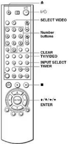
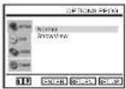
Press TIMER.
The "OPTIONS PROG." menu appears.
44
Recording TV programmes using the ShowView® system (SLV-D950B only)
5

If you want to change the date, tape speed and the VPS/PDC setting:
1 Press ✦/♦ to select the item you want to change.
2 Press ♦/♦ in reset it.
- To record the same programme every the same day every week, see "Daily/weekly recording" on page 46.
- To use the VPS/PDC function, set "V/P" to "Oui". For details about the VPS/PDC function, see "Timer recording with VPS/PDC signals" on page 46.
6

Press ENTER to confirm the setting.
7

Press ENTER to confirm all settings.
8

Press I/ ^① to turn off the DVD-VCR.
The indicator appears in the display window and the VCR stands by for recording.
To record from a decoder or other source, leave the connected equipment switched on.
To stop recording
To stop the DVD-VCR while recording, press SELECT VIDEO and then press ■
Daily/weekly recording
In step 5 above, press ↓ to select the recording pattern. Each time you press ↓, the indication changes as shown below. Press ↓ to change the indication in reverse order today → JOUR (Monday to Sunday) → S-SA (every Saturday) ..... → S-DI (every Sunday) → 1 month later → (dates count down) → today
Timer recording with VPS/PDC signals
Some broadcast systems transmit VPS or PDC signals with their TV programmes. These signals ensure that your timer recordings are made regardless of broadcast delays, early starts, or broadcast interruptions.
To use the VPS/PDC function, set "V/P" to "Oui" in step 5 above. You can also use the VPS/PDC function for a source connected to one or more of the LINE inputs.
46
Recording TV programmes using the ShowView® system (SLV-D950B only)
2

Press ♦/♦ to select "ShowView", then press ENTER.
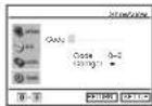
The "ShowView" menu appears.
3

Press the number buttons to enter the ShowView number. If you make a mistake, press CLEAR and re-enter the correct number.
You can also press ✦ to delete the last entered number.
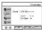

Press ENTER.
10
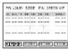
The date, start and stop times, programme position, tape speed and VPS (Video Programme System)/PDC (Programme Delivery Control) setting appear on the TV screen.
- If “” appears in the “PR” (programme) column (this may happen for local broadcasts), you have to set the appropriate programme position manually. Press ♦/♦ to select the desired programme position. - To record from a decoder or other source connected to one or more of the LINH inputs, press INPUT SELECT to display the connected line in the “PR” position.
You will only have to do this operation once for the referred channel. The VCR will then store your selling.
If the information is incorrect, press CLEAR to cancel the setting.
Basic Operations
continued
Recording TV programmes using the ShowView® system (SLV-D950B only)
45
To watch another TV programme after setting the timer
1
Press TV/VIDEO to display "TV" in the display window.
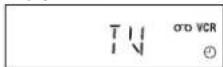
2 If your TV is connected to the VCR using A/V connections, set the TV to the TV's aerial input: if not, skip this step.
3 Select another channel on the TV.
Tips
• To set the channel, you can also use the ♦/♦ or number buttons.
- If the indicator appears, this means that the VCR is currently recording this programme.
- You can also do the following tasks while the VCR is recording:
- Reset the counter(page 39).
- Display tape information on the TV screen (page 41).
To use the Auto Tape Speed function
In step 5 above, press ♦ to select "Auto". When you are recording a programme in the SP mode and the remaining tape length becomes shorter than the recording time, the recording tape speed is automatically changed to the LP mode. Note that some noise will appear on the picture when the tape speed is changed. To operate this function correctly, the "Select, Cassette" setting in the "REGLAGE DE LA FONCTION VIDEO" menu must be accurate (see page 105).
Tips
- To set the line input video source, you can also use the INPUT SELECT button.
- You can set the extended time for the ShowView setting by 10, 20, 30, 40, 50, or 60 minutes. Set "Elendre ShowView" in the "REGLACES UTILISATEUR" menu to the desired extended time on page 110.
- To check, change, or cancel the programme setting, see "Checking/changing/cancelling timer settings" on page 56.
Notes
- If the VPS/PDC signal is too weak or the broadcasting station failed to transmit VPS/PDC signals, the VCR will start recording at the set time without using the VPS/PDC function.
- The Ⓑ indicator flashes in the display window when you press I/○ with no tape inserted.
Basic Operations
Recording TV programmes using the ShowView® system (SLV-D950B only)
47
Recording TV programmes using the timer
VHS
You can preset up to six programmes at a time.
Before you start..
• C. heck that the DVD-VCR clock is set to the correct time.
• T ur n on the DVD-VCR and your TV.
- S witch the input selector on your TV so that the signal from the player appears on the TV screen.
- S e⊥ /DVD-VIDEO to DVD-VIDEO, then press SELECT VIDEO to control the VCR (page 9).
- When using a decoder, turn it on.
- Insert a tape with its safety tab in place. Make sure the tape is longer than the total recording time.
- If the DVD player is in play mode, you cannot display the setup menu. Stop the DVD playback.
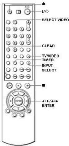
48
Recording TV programmes using the timer
5

Press ENTER to confirm all settings.
6

Press I/O to turn off the DVD-VCR.
The indicator appears in the display window and the VCR stands by for recording.
Torccord from a decoder or other source, leave the connected equipment switched on.
To stop recording
To stop the DVD-VCR while recording, press SELECT VIDEO and then press ■.
Dally/weekly recording
In step 3 above, press ♦ to select the recording pattern. Each time you press ♦, the indication changes as shown below. Press ♦ to change the indication in reverse order.
today → JOUR (Monday to Sunday) → S-SA (every Saturday) ..... → S-DI (every Sunday) → 1 month later → (dates count down) → today
To use the Auto Tape Speed function
In step 3 above, press to select "Auto". When you are recording a programme in the SP mode and the remaining tape length becomes shorter than the recording time the recording tape speed is automatically changed to the LP mode. Note that some noise will appear on the picture when the tape speed is changed. To operate this function correctly, the "Select Cassette" setting in the "REGLAGE DE LA FONCTION VIDEO" mean must be accurate (see page 105).
Tips
- To set the line input video source, you can also use the INPUT SELECT button. - To check, change, or cancel the programme setting, see "Checking/changing/cancelling timer settings" on page 56.
Notes
- When setting the timer with VPS/PDC signals, enter the start times exactly as indicated in the TV programmatic guide. Otherwise, the VPS/PDC function will not work.
- If the VPS/PDC signal is too weak or the broadcasting station failed to transmit VPS/PDC signals, the VCR will start recording at the set time without using the VPS/PDC function.
- The indicator flashes in the display window when you press 1/1 with no tape inserted.
1

Press TIMER.
• S L V - D 950B
The "OPTIONS PROG." menu appears.
• S I. V - D 910B
The timer programming menu appears. Step 2 is skipped.
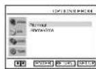
2

SLV-D950B only Press ♦/♦ to select "Normal", then press ENTER. The timer programming menu appears.
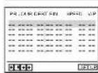
3

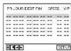
Set the date, start and stop times, programme position, tape speed and VPS/PDC function: 1 Press ♦ to select each item in turn. 2 Press ♦/♦ to set each item. To correct a setting, press ♦ to return to that setting and reset.
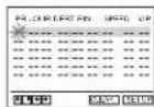
- To record the same programme every day or the same day every week, see "Daily/weekly recording" on page 50. - To use the VPS/PDC function, set "V/P" to "Oui." For details about the VPS/PDC function, see "Timer recording with VPS/PDC signals" on page 46. - To record from a december or other source connected to one or more of the LINE inputs, press INPUT SELECT to display the connected line in the "PR" position.

4

Press ENTER to confirm the setting. To enter another setting, press ♦/♦ to select the next row and repeat step 3. Press CLEAR to cancel the setting.

continued
Recording TV programmes using the timer
49
To watch another TV programme after setting the timer
1 Press TV/VIDEO to display "TV" in the display window.
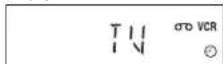
2 If your TV is connected to the VCR using A/V connections, set the TV to the TV's aerial input; if not, skip this step. 3 Select another channel on the TV.
Tips
- To set the channel, you can also use the +/♦ or number buttons. - If the ○ indicator appears, this means that the VCR is currently recording this programme. - You can also do the following tasks while the VCR is recording: - Reset the counter (page 39). - D is play tape information on the TV screen (page 41).
50
Recording TV programmes using the timer
Recording TV programmes using the timer
51
Recording TV programmes using DIAL TIMER (SLV-D950B only) VHS
The Dial Timer function allows you to make timer recordings of programmes without turning on your TV. Set the recording timer to record up to six programmes that will be broadcast within a month using DIAL TIMER. The recording start time and recording stop time can be set at one minute intervals.
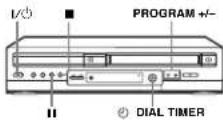
Before you start...
• Turn on the DVD-VCR.
- When using a decoder, turn it on.
- Insert a tape with its safety tab in place. Make sure the tape is longer than the total recording time.
- Stop the DVD-VCR.
1
© DISL-TIFF
Press © DIAL. TIMER.
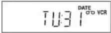
DATE indicator appears and the current date flashes in the display window. If the date and time are not set, DAY indicator will appear. To set the date and time, see "To set the clock" on page 55.
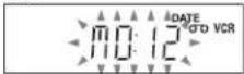
2
DIGLTimer Turn DIGL TIMER to set the recording date.

52
Recording TV programmes using DIAL TIMER (SLV-D950B only)
7
© DIAL THER
Press © DIAL TIMER.

The current programme position number flashes in the display window.
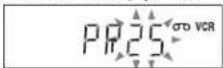
8
CIAL TIMER
Turn DIAL TIMER to set the programme position number.

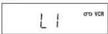
To record from a source connected to the LINE-1 connector, LINE-2 IN jacks or LINE-3 connector, turn ⏻ DIAL TIMER or press INPUT SELECT to display "L1", "L2" or "L3".

9
© CIAL TIMER
Press © DIAL. TIMER.

The current tape speed flashes in the display window.
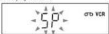
1
© 214 TAFE
Turn ∅IAL TIMER to set the tape speed.


1
Φ14 THER
Press DIAL TIMER to complete the setting.

"OK" appears in the display window for about five seconds. The timer indicator appears in the display window and the VCR stands by for recording. When using a decoder, leave it on.
To return to the previous step
To return to the previous step, press the PROGRAM + and - buttons on the unit at the same time during any of the Dial Timer settings.
54
Recording TV programmes using DIAL TIMER (SLV-D950B only)
3
© LOW TIMER
Press DIAL TIMER to set the start time.

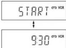
"START" and the next quarter hour increment appear alternately in the display window.
4
© DWL TIMER
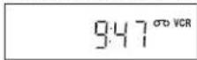
Turn @DIAL TIMER to set the recording start time.

You can set the recording start time in 15 minute intervals or adjust the time in one minute intervals by pressing the PROGRAM +/- buttons on the unit.
5
© DAI TIME
Press DIAL TIMER to set the stop time.

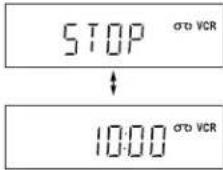
"STOP" and the next quarter hour increment appear alternately in the display window.
6
DWL TIMER
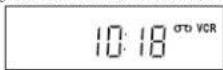
Turn DIAL TIMER to set the recording stop time.

You can set the recording stop time in 15 minute intervals or adjust the time in one minute intervals by pressing the PROGRAM +/- buttons on the unit.
continued
Recording TV programmes using DIAL TIMER (SLV-D950B only
Basic Operations
PROGRAM


53
To set the clock
1 Hold down ⒹDIAL TIMER so that DAY indicator appears in the display window. However, if the clock has already been set, the current setting appears.
2 Turn DIAL TIMER to set the day.
3 Press ⏻ DIAL TIMER.
MONTH indicator appears in the display window
4 Turn and press ⒹDIAL. TIMER to set the month and then the year.
After you set the year, "CLOCK" appears in the display window.
5 Turn and press ⒹDIAL. TIMER to set the hour and minute.
6 When you have finished setting the time, press ⒹDIAL TIMER to start the clock.
Tips
- T o cancel a Dial Timer setting, press any button other than DIAL TIMER or PROGRAM +/- on the unit or any button on the remote while you are making the setting
- To check, change, or cancel the programme setting, see "Checking/changing/cancelling timer settings" on page 56.
Notes
- If six programmes have already been set using the ShowView system or the manual timer setting, "TILL" appears in the display window for about five seconds.
- If you set the clock using the Auto Clock Set feature, the clock will adjust itself to the incoming time signal regardless of adjustments made with DIAL. TIMER. Be sure you have set Auto Clock Set correctly.
- If you are setting the clock for the first time or "0: " appears in the display window, you cannot set the clock to February 29 using DIAL TIMER. Please use the Auto Clock Set feature to set the VCR to this day.
- The indicator flashes in the display window when you complete the setting in step 11 on page 34 with no tape inserted.
- When the setting time is incorrect, "Error" appears in the display window in step 11. Set the tumor again from step 1.
About the Demonstration Mode
The Dial Timer function has a Demonstration Mode that allows the user, such as a salesperson, to enter more than six examples of timer settings when demonstrating the use of DIAL.TIMER. It cancels the FULL notice which appears if six programmes have already been set. Do not use the Demonstration Mode for making timer recordings. Doing so may cause the settings to be inaccurate.
To activate the Demonstration Mode
Press II on the unit while turning (DIAL, TIMER, "DEMO" appears in the display window for a few seconds.
To cancel the Demonstration Mode
Turn the power off and unplug the mains lead. Although the Demonstration Mode is cancelled, the timer settings entered while using the Demonstration Mode will remain. Be sure to manually cancel the timer settings before you use DIAL TIMER or any other timer method after reconnecting the mains lead (page 56).
Recording TV programmes using DIAL TIMER (SLV-D950B only
Basic Operations
Checking/changing/cancelling timer settings VHS
Before you start..
- C hock that the DVD-VCR clock is set to the correct time.
• T ur n on the DVD-VCR and your TV. - S witch the input selector on your TV so that the signal from the player appears on the TV screen.
- S c t /DVD-VIDEO to DVD-VIDEO. then press SELECT VIDEO to control the VCR (page 9).
- When using a decoder, turn it on.
- Insert a tape with its safety tab in place. Make sure the tape is longer than the total recording time.
- If the DVD player is in play mode, you cannot display the setup menu. Stop the DVD playback.
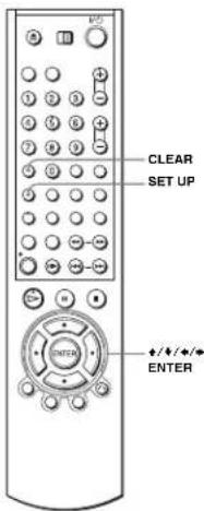
56
Checking/changing/cancelling timer settings
When the timer settings overlap
The programme that starts first has priority and the second programme starts recording only after the first programme has finished. If the programmes start at the same time, the programme listed first in the menu has priority.
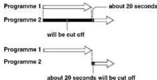
flowchart
graph LR
    A["Programme 1"] --> B["Programme 2"]
    B --> C["will be cut off"]
    D["Programme 1"] --> E["Programme 2"]
    E --> F["will be cut off"]
    style A fill:#f9f,stroke:#333
    style D fill:#f9f,stroke:#333
    style B fill:#ccf,stroke:#333
    style E fill:#ccf,stroke:#333
    note1["about 20 seconds"]
    note2["will be cut off"]
    note3["about 20 seconds will be cut off"]
58
Checking/changing/cancelling timer settings
1

Press SET UP, then press ♦/♦ to select (TIMER) and press ENTER.
• S L V - D 950B The "OPTIONS PROG." menu appears.

• S L V - D 910B The timer programming menu appears. Step 2 is skipped.
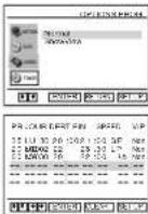
2

SLV-D950B only Press ♦/♦ to select "Normal", then press ENTER. • If you want to change a setting, go on to the next step. • If you do not need to change the settings, press SET UP to exit the menu.

3

Press ♦/♦ to select setting you want to change or cancel. • To change the setting, press ♦/♦ to flash the item you want to change, and press ♦/♦ to change it. • To cancel the setting, press CLEAR.
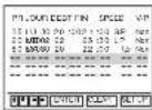
4

Press ENTER to confirm the setting. If any settings remain, turn off the VCR to return to recording standby.
continued
Checking/changing/cancelling timer settings
57
Advanced Hookups
A/V Receiver hookup DVD VCD CD DATA-CD VHS
A Use this hookup if your A/V receiver has a Dolby • Surround (Pro Logic) decoder and 3 to 6 speakers
You can enjoy the Dolby Surround effects only when playing Dolby Surround audio or multi-channel audio (Dolby Digital) discs.
- Manufactured under license from Dolby Laboratories. "Dolby," "Pro Logic," and the double D symbol are trademarks of Dolby Laboratories.
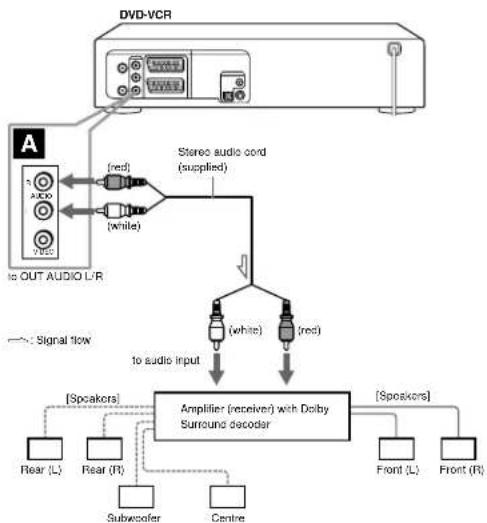
flowchart
graph TD
    A["DVCD-VCR"] --> B["Audio"]
    B --> C["To OUT AUDIO L/R"]
    C --> D["Red/White ports"]
    D --> E["Stereo audio cord (supplied)"]
    E --> F["Amplifier (receiver) with Dolby Surround decoder"]
    F --> G["Speaker 1: Rear (L)"]
    F --> H["Speaker 2: Rear (R)"]
    F --> I["Speaker 3: Subwoofer"]
    F --> J["Speaker 4: Centre"]
    F --> K["Speaker 5: Front (L)"]
    F --> L["Speaker 6: Front (R)"]
    style A fill:#f9f,stroke:#333
    style B fill:#ccf,stroke:#333
    style C fill:#cfc,stroke:#333
    style D fill:#fcc,stroke:#333
    style E fill:#cff,stroke:#333
    style F fill:#ffc,stroke:#333
    style G fill:#cfc,stroke:#333
    style H fill:#cfc,stroke:#333
    style I fill:#cfc,stroke:#333
    style J fill:#cfc,stroke:#333
    style K fill:#cfc,stroke:#333
    style L fill:#cfc,stroke:#333
Advanced Hookups
continued
A/V Receiver hookup
59
B Use this hookup if your A/V receiver has a Dolby Digital, MPEG audio or DTS • decoder, a digital Input jack and 6 speakers
This connection will allow you to use the Dolby Digital, MPEG audio or DTS decoder function of your AV amplifier (receiver). You are not able to enjoy the surround sound effects of this player. You must make connections using B-1

• "DTS" and "DTS Digital Out" are trademarks of Digital Theater Systems, Inc.
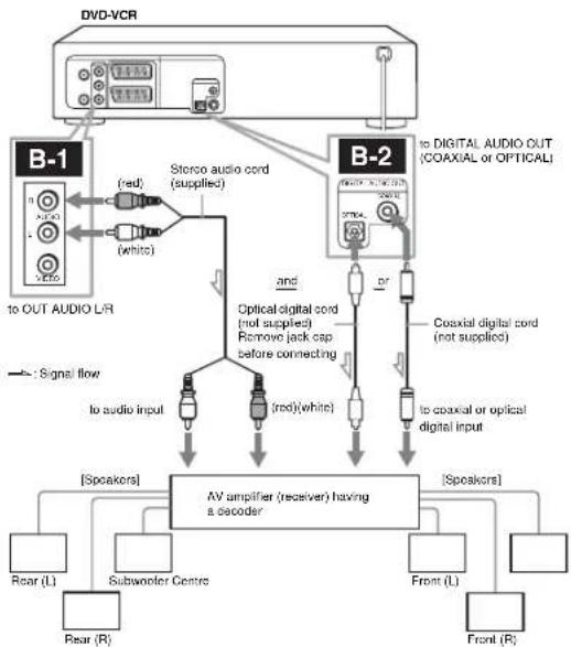
flowchart
graph TD
    A["DVD-VCR"] --> B["B-1"]
    A --> C["B-2"]
    B --> D["Storco audio cord (supplied)"]
    C --> E["Optical digital cord (not supplied)"]
    C --> F["Coaxial digital cord (not supplied)"]
    D --> G["AV amplifier (receiver) having a decoder"]
    E --> G
    F --> G
    G --> H["Rear (L)"]
    G --> I["Subwoofer Centre"]
    G --> J["Front (L)"]
    G --> K["Front (R)"]
    B --> L["to OUT AUDIO L/R"]
    C --> M["to digital AUDIO OUT (COAXIAL or OPTICAL)"]
    D --> N["Signal flow"]
    E --> O["to audio input"]
    F --> P["red(white)"]
    G --> Q["red(white)"]
    H --> R["Rear (R)"]
    I --> S["Rear (R)"]
    J --> T["Rear (R)"]
    K --> U["Rear (R)"]
Note
After you have completed the connection, he sure to set "Dolby Digital" to "Dolby Digital" and "DTS" to "Oel" in "OPTIONS AUDIO" menu (page 62). If your AV amplifier (receiver) has an MPEG audio decoder function, set "MPEG" to "MPEG" in "OPTIONS AUDIO" menu (page 62). Otherwise, no sound or a loud noise will come from the speakers.

A/V Receiver hookup
DVD Settings and Adjustments
Audio Setup DVD
"Options Audio" allows you to set the sound according to the playback and connection conditions.
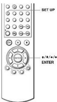


Press SET UP when the DVD player is in stop mode, then press ♦/♦ to select 📄 (DVD) and press ENTER.


Press ↑/↓ to select "Options Audio", then press ENTER.
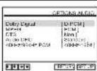


Press ♦/♦ to select the setup item from the displayed list: "Dolby Digital", "MPEG", "DTS", "Audio DRC", or "48kHz/96kHz PCM".

Audio Setup
S-Video hookup DVD VCD DATA-CD
Make audio connections using the OUT AUDIO L/R jacks or DIGITAL. AUDIO OUT (OPTICAL or COAXIAL) jacks when you use S-VIDEO hookup.
Use this hookup if your TV has an S VIDEO input jack
- C connect an S VIDEO cord (not supplied). You will enjoy high quality images.
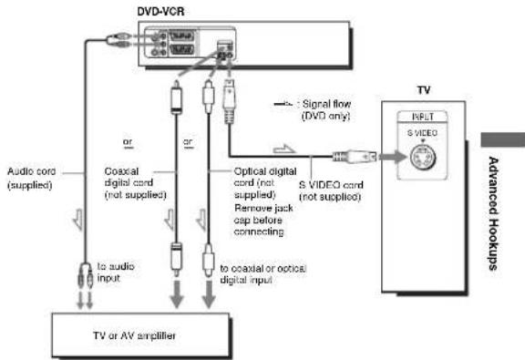
flowchart
graph TD
    A["TV or AV amplifier"] --> B["TV"]
    B --> C["Advanced Hookups"]
    C --> D["Signal flow (DVD only)"]
    D --> E["Optical digital cord (not supplied)"]
    D --> F["S VIDEO cord (not supplied)"]
    E --> G["Remove jack cap before connecting"]
    F --> H["to coastal or optical digital input"]
    G --> I["to audio input"]
    H --> J["to audio cord (supplied)"]
    I --> K["Coaxial digital cord (not supplied)"]
    J --> L["Audio cord (supplied)"]
    K --> M["DV-DVR"]
Notes
- Set "DVD S-Video Out" to "Out" in the "REGLAGE DE LTECLAN" menu (page 65) to view pictures from the S-VIDEO jack.
- The connection using S VIDEO OUT jack is only for the DVD player.
S-Video hookup
61


Press ♦/♦ to select an item.


Press SET UP to exit the menu.
Menu choices
• D olby Digital
Selects the type of Dolby Digital signal
The default setting is indicated in bold print.
| D-PCM | Select this when the player is connected to an audio component lacking a built-in Dolby Digital decoder. |
| Dolby Digital | Select this when the player is connected to an audio component with a built-in Dolby Digital decoder. |
• M P E G
Selects the type of MPEG audio signal.
The default setting is indicated in bold print
| PCM | Select this when the player is connected to an audio component lacking a built-in MPEG decoder. If you play MPEG audio sound tracks, the player outputs stereo signals via the DIGITAL AUDIO OUT (OPTICAL or COAXIAL) jack. |
| MPEG | Select this when the player is connected to an audio component with a built-in MPEG decoder. |
• DTS
Selects whether or not to output DTS signals.
The default setting is indicated in hold print.
| Non | Select this when the player is connected to an audio component lacking a built-in DTS decoder. |
| Oui | Select this when the player is connected to an audio component with a built-in DTS decoder. |
DVD Settings and Adjustments
continued
Audio Setup
63
• Audio DRC (Dynamic Range Control)
Makes the sound clear when the volume is turned down when playing a DVD that conforms to "Audio DRC". This affects the output from the following jacks: - OUT AUDIO L/R jacks
- D IGITAI. AUDIO OUT (OPTICAL or COAXIAL) jack only when "Dolby Digital" is set to "D-PCM".
The default setting is indicated in bold print.
| Standard Normally select this position. |
| TV Makes the low sounds clear even if you turn the volume down. |
4 8kHz/96kHz PCM
Selects the sampling frequency of the audio signal. The default setting is indicated in bold print.
| 48kHz/16bit The audio signals of DVD VIDEOS are always converted to 48 kHz/16 bit. | |
| 96kHz/24bit | All types of signals including 96 kHz/24 bit are output in their original format. However, if the signal is encrypted for copyright protection purposes, the signal is only output as 48 kHz/16 bit. |
Notes
- If you select the surround setting while playing a DVD, the player does not output the following signals from the DIGITAL AUDIO OUT (OPTICAL, or COAXIAL) jack. D u l by Digital signals (when you set "Dolby Digital" to "D PCM" in "OPTIONS AUDIO" menu)
M PEG audio signals
- If you connect a component that does not conform to the selected audio signal, a loud noise (or no sound) will come out from the speakers, affecting your ears or causing the speakers to be damaged.
- Even if you set "48kHz/96kHz PCM" to "96kHz/24bit", the sampling frequency is converted to 48 kHz/16 bit when a "SURROUND" mode (page 83) is selected.
- The analog audio signals from AUDIO OUT L/R jacks are not affected by "48kHz/96kHz PCM" setting and keep their original sampling frequency level.
Screen Setup DVD
"Réglage de L'écran" allows you to set the screen according to the playback and connection conditions.
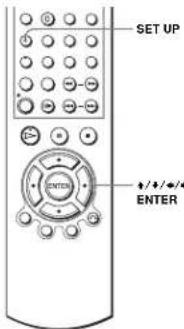
1


SET UP Press SET UP when the DVD player is in stop mode, then press ♦/♦ to select (DVD) and press ENTER.

2
3
Press ♦/♦ to select the setup item from the displayed list: "Type TV", "DVD LINE1 RVB Out" or "DVD S-Video Out".
continued
Screen Setup
65
64
Audio Setup
4

Press ♦/♦ to select an item.
5

Press SET UP to exit the menu.
Menu choices
• Type TV
Selects the aspect ratio of the connected TV (4:3 standard or wide). The default setting is indicated in bold print.
| 4:3 Letter Box Select this when you connect a 4:3 screen TV. Displays a wide picture with beads on the upper and lower portions of the screen. | |
| 4:3 Pan Scan | Select this when you connect a 4:3 screen TV. Automatically displays the wide picture on the entire screen and cuts off the portions that do not fit. |
| 16:9 | Select this when you connect a wide-screen TV or a TV with a wide made function. |

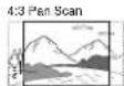
• D VD LINEI RVB Out
Selects the method of outputting video signals from the LINE-1 (EURO AV) jack on the rear panel of the player.
The default setting is indicated in bold print.
| Non | Select this to not output RGB signals. |
| Oul | Select this to output RGB signals. |
• D VD S-Video Out
Selects whether or not to output S video signals from the S-VIDEO OUT jack on the rear panel of the player.
The default setting is indicated in bold print.
| Oui | Select this when the player is connected to a TV with 5 VIDEO input jack. |
| Non | Select this when the player is connected to a TV lacking 5 VIDEO input jack. |
Notes
- Playback settings stored in the disc take priority over the "REGLAGE DU DVD" menu settings and not all the functions described may work.
- Depending on the DVD. "4:3 Letter Box" may be selected automatically instead of "4:3 Pan Scan" or vice versa.
• The connection using S VIDEO OUT jack is only for the DVD player. - When you select "Oui" in the "DVD LINE1 RVB Our" setting, "DVD S-Viden Our" is set to "Non" automatically.
- While you select "Out" in the "DVD S Video Out" setting, "DVD LINE1 RVB Out" is set to "Non" automatically.
66
Screen Setup
Screen Setup
67
Setting the display or sound track language DVD
You can set various languages for the disc's menu, sound track or subtitle.
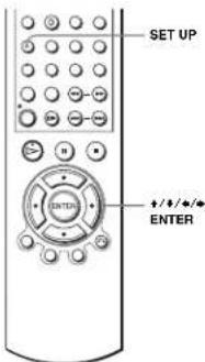
1
Press SET UP when the DVD player is in stop mode, then press ♦/♦ to select (DVD) and press ENTER.
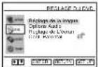
2

Press ♦/♦ to select "Réglage de la langue", then press ENTER.
The "REGLAGE DE LA LANGUE" menu appears.
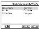
3

Press ♦/♦ to select the language setup item from the displayed list, "Menu DVD", "Audio", or "Sous-Title". Then press ENTER.
68
Setting the display or sound track language
Parental Control (limiting playback by children)
DVD
Playback of some DVDs can be limited according to a predetermined level such as the age of the users. The parental control function allows you to set a playback limitation level.
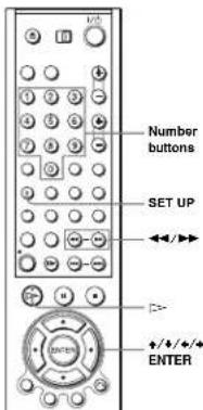
1

Press SET UP when the DVD player is in stop mode, then press ♦/♦ to select 📄 (DVD) and press ENTER.
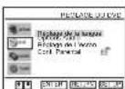

2

Press ♦/♦ to select "Cont. Parental", then press ENTER.
70
Parental Control (limiting playback by children)
4

Press ♦/♦ to select the desired language, then press ENTER.
• L A NGUE DE MENU DVD You can select the desired language for the disc's menu.
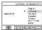
• L. A. NGUE DE LA BANDE SON Switches the language of the sound track. When you select "Originale", the language given priority in the disc is selected.
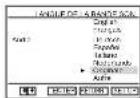
• L. A NGUE DES SOUS-TITRES Switches the language of the subtitle recorded on the DVD.
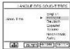
5

Press SET UP to exit the menu.
Tip
- I if you select "Autre" in step 4, an additional language menu appears. Press ♦/♦/♦/♦ to select the desired language, then press ENTER.
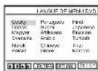
Notes
- When you select a language that is not recorded on the DVD in step 4, one of the recorded languages will be automatically selected.
- Playback settings stored in the disc take priority over the REGLAGE DU DVD settings and not all the functions described may make.
- If you change the LANGUE DE MENU DVD setting after playing the disc, press ▲ to open and close the disc may to activate the new setting, then play the disc again.
Setting the display or sound track language
69
3

Press ➔ to select "Oui".
- If you have not entered a password The display for registering a new password appears. Enter a 4-digit password using the number buttons.
The display for confirming the password appears. Re-enter the password.
- When you have already registered a password The display for entering the password appears. Enter a 4-digit password using the number buttons.
Press ♠/♦ to select the level you want, then press ENTER.
The options are as follows. Level 8 (Adultie) Level 7 Level 6 Level 5 Level 4 Level 3 Level 2 Level 1 (Tout Public) The lower the value, the stricter the limitation
6

Press SET UP to exit the menu.
continued
Parental Control (limiting playback by children)
To change the password
1 Select "Modif. Code Secret" in step 4 on page 71.
2 Enter a new 4-digit password using the number buttons. The display for confirming the password appears.
3 Re-enter the new password.
To turn off the Parental Control function
Set "Utiliser le Code" to "Non" in step 3 on page 71.
To play a disc for which Parental Control is set
1 Insert the disc, then press ▷.
The display for entering your password appears.
2 Enter your 4-digit password using the number buttons. The player starts playback.
If you forget your password
1 Remove the disc and turn off the DVD-VCR.
2 Turn on the DVD-VCR again with no disc in the unit.
3 Hold down ◀◀ and ▶▶ on the front panel simultaneously for 5 seconds. "Reset OK" appears on the screen.
4 Turn off the DVD-VCR.
The password is cleared.
5 To create a new password, follow step 3 on page 71
Notes
- While you play DVDs which do not have the Parental Control function, playback cannot be limited on this player.
- All the ratings higher than the level you select will be blocked.
- Write your password down and keep it in a safe place in case you forget it.
72 | Parental Control (limiting playback by children)
3
Press ENTER.

To turn off the DVD's menu
Press ■
Note
• D e p e nding on the DVD, you may not be able to use the TOP MENU button.
74 | Using the DVD's menu
DVD Additional Operations
Using the DVD's menu DVD
A DVD is divided into long sections of a picture or a music feature called "titles". When you play a DVD which contains several titles, you can select the title you want using the TOP MENU button.
When you play DVDs that allow you to select items such as the language for the subtitles and the language for the sound, select these items using the MENU button.
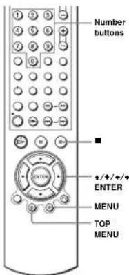
1

Press TOP MENU or MENU.
C
TOP MENU
O
C
MENU
(No text)


Press ♦/♦/♦/♦ to select the item you want to play or change. You can also use the number buttons to select the item.
2
continued
Using the DVD's menu
73
Zooming into a scene DVD VCD DATA-CD
You can zoom into a scene during playback or still mode.
To zoom into a JPEG image, see "Playing JPEG image files" on page 89.
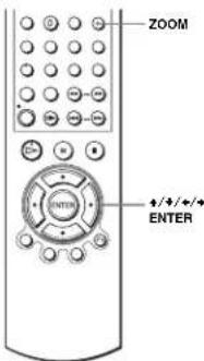
1

Press ZOOM
“是”
appears.
2

Press ♦/♦/♦/♦ to move “■” to the position where you want to zoom in.
3

Press ENTER repeatedly to change the magnification. Each time you press the button, the magnification changes as shown below. 2 → 4 → 2 → normal magnification
Notes
- Y ou cannot use a magnification when you play VIDEO CDs. - T he zona function may not work depending on the DVD.
Zooming into a scene
75
Changing the angles DVD
If various angles (multi-angles) for a scene are recorded on the DVD, "appears in the display when you press ANGLE during playback. This means that you can change the viewing angle.
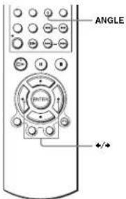
1

Press ANGLE during playback. The angle number appears on the display. The number after the slash indicates the total number of angles.
2

Press ♦/♦ repeatedly to select the angle number. The scene changes to the selected angle.
Note
• D is p. ending on the DVD, you may not be able to change the angles even if multi-angles are recorded on the DVD.
76
Changing the angles
Various play mode functions (Programme play, Shuffle play, Repeat play) DVD VCD CD DATA-CD
You can set the following play modes:
• P r ogramme play (page 78)
- S h u f f le play (page 80)
• R e p eat play (page 81)
Note
• The play mode is cancelled when:
- y ou open the disc tray
the player enters standby mode by pressing I/O.
Creating your own programme (Programme play)
You can play the contents of a disc in the order you want by arranging the order of the tracks on the disc to create your own programme. You can programme up to 20 tracks.
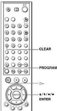
1

Press PROGRAM when the DVD player is in stop mode.
78
Various play mode functions (Programme play, Shuffle play, Repeat play)
Displaying the subtitle DVD
If subtitles are recorded on the disc, you can change the subtitles or turn them on and off whenever you want while playing a DVD.
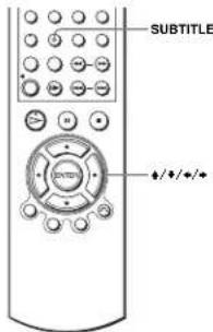
1

Press SUBTITLE during playback.
2

Press ♦/♦ repeatedly to select the language.
Depending on the DVD, the choice of language varies.
Refer to "DVD Audio/Subtitle Language" on page 126 for the abbreviation of the language.
3

Press ♦/♦ repeatedly to select "Oui".
To turn off the subtitles
Select "Non" in step 3.
Note
- Depending on the DVD, you may not be able to change the subtitles even if multilingual subtitles are recorded on the DVD. You also may not be able to turn them off.
Displaying the subtille
77
2

Press ◀/◆ to select "PROGRAMMATION", then press ENTER.
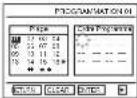
3

Press ♠/♦/♦/♦ to select the track number you want to programme, then press ENTER.
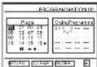
4
To programme other tracks, repeat step 3.
The programmed track numbers are displayed in the selected order.
5

Press => to start programme play.
Programme play starts.
When the programme ends, you can restart the same programme again by pressing [> .
To stop programme play
Press CLEAR during programme play.
To change or cancel a programme
1 Follow steps 1 and 2 of "Creating your own programme (Programme play)".
2 Press CLEAR
The last programmed number is cancelled.
3 Follow step 3 for new programming.
DVD Additional Operations
continued
Various play mode functions (Programme play, Shuffle play, Repeat play)
79
Playing in random order (Shuffle play)
You can shuffle the playback order of tracks. Subsequent "shuffling" may produce a different playing order.
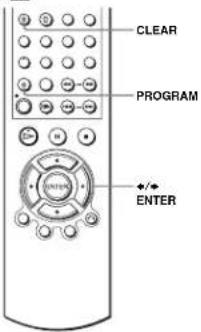
1

Press PROGRAM when the DVD player is in stop mode.
2

Press ♦/♦ to select "ALEATOIRE", then press ENTER.
To return to normal play
Press CLEAR during shuffle play.
80
Various play mode functions (Programme play, Shuffle play, Repeat play)
Changing the sound DVD VCD CD
When playing a DVD recorded in multiple audio formats (PCM, Dolby Digital, MPEG or DTS), you can change the audio format. If the DVD is recorded with multilingual tracks, you can also change the language.
With CDs, DATA CDs, or VIDEO CDs, you can select the sound from the right or left channel and listen to the sound of the selected channel through both the right and left speakers. For example, when playing a disc containing a song with the vocals on the right channel and the instruments on the left channel, you can hear the instruments from both speakers by selecting the left channel.
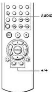
1

Press AUDIO during playback.
2

Press ♦/♦ repeatedly to select the desired language/audio setting.
- When playing a DVD
Depending on the DVD, the choice of language varies. Refer to "DVD Audio/Subtitle Language" on page 126 for the abbreviation of the language.
- When playing a VIDEO CD or CD The default setting is indicated in bold print
| Stereo | The standard stereo sound |
| Ganche | The sound of the left channel (monaural) |
| Droite | The sound of the right channel (monaural) |
82
Changing the sound
Playing repeatedly (Repeat play) DVD VCD CD DATA-CD
You can play all of the titles or tracks on a disc or a single title, chapter, or track repeatedly.
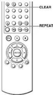
1

Press REPEAT during playback.
2

Press REPEAT to select the item to be repeated.
When playing a DVD
• C chapter: repeats the current chapter.
• Title: repeats the current title on a disc.
When playing a VIDEO CD or CD
- T rack: repeats the current track.
• D isc; repeats all of the tracks.
When playing a DATA CD (MP3 audio)
• T rack: repeats the current track.
To return to normal play
Select "Non" in step 2 or press CLEAR during repeat play.
Tip
- When playing a DATA CD, press REPEAT again to cancel repeat play.
Various play mode functions (Programme play, Shuffle play, Repeal play)
81
Virtual surround setting DVD
When you connect a stereo TV or 2 front speakers, SURROUND lets you enjoy surround sound effects by using sound imaging to create virtual rear speakers from the sound of the front speakers without using actual rear speakers.
This function is designed to work with the OUT AUDIO I/R jacks.
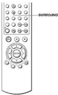
1

Press SURROUND during playback.
2

Press SURROUND repeatedly to select "Oui".
To cancel the setting
Select "Non" in step 2.
DVD Additional Operations
continued
Virtual surround setting
83
Notes
• S. surround effects cannot be obtained for DTS or linear PCM
- When the playing signal does not contain a signal for the rear speakers, the surround effects will be difficult to hear.
- When you activate the surround effect, turn off the surround setting of the connected TV or amplifier (receiver).
- Make sure that your listening position is between and at an equal distance from your sneakers, and that the sneakers are located in similar surroundings.
- If you use the DIGITAL AUDIO OUT (OPTICAL or COAXIAL) jack and set "Dolby Digital" to "Dolby Digital" or "DTS" to "Oui" in "OPTIONS AUDIO" menu, sound will come from your speakers but it will not have the surround effect.
- Certain audio features of this product manufactured under a license from Desper Products, Inc. Spatializer®, VBXTM and the circle-in-square device are trademarks owned by Desper Products, Inc.
Playing an MP3 audio track DATA-CD
You can play back DATA CDs (CD-ROMs/CD-Rs/CD-RWs) recorded in MP3 (MPEG1 Audio Layer 3) format.
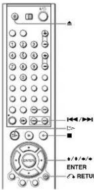
1

Press ▲ and place a DATA CD on the disc tray, then press ▲ to close the tray.
When you load a DATA CD which contains MP3 audio tracks and JPEG image files, "Sélectionnez le type de media" meau appears. If you load a DATA CD which contains only MP3 audio files, the MP3 display appears. Then you can skip step 2.
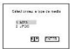
2

Press ♦/♦ to select "MP3", then press ENTER.
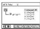
continued
Playing an MP3 audio track
85
84
Virtual surround setting
3

Press ♦/♦ then press ENTER, or press ◀◀◀ /▶▶ to select the desired track.

The selected track starts playing.
When a track or album is being played, its title is shaded. The playing track number appears on the display window.

To change the album, press 📌 RETURN.
RETURN
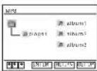
4

Press ↑/↓ to select an album, then press ENTER.
The list of tracks contained in the album appears.
To select a track, repeat step 2.
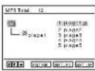
To go to the next or previous page
Press ♦ or ♦.
To return to the previous display
Press 📞 RETURN.
To turn off the display
Press ■, then press ⬆ RETURN repeatedly.
Notes
- Only the letters in the alphaher and numbers can be used for album or track names. Anything else is displayed as an asterisk.
- U p t o 8 alphanumeric characters can be displayed for album or track names. - 1 D3 taps cannot be displayed.
About MP3 audio tracks
You can play MP3 audio tracks on CD-ROMs, CD-Rs, or CD-RWs. However, the discs must be recorded according to ISO9660 level 1, level 2, or Joliet format for the player to recognize the tracks.
You can also play discs recorded in Multi Session.
See the instructions of the CD-R/RW device or recording software (not supplied) for details on the recording format.
86
Playing an MP3 audio track
To play a Multi Session CD
This player can play Multi Session CDs when an MP3 audio track is located in the first session. Any subsequent MP3 audio tracks, recorded in the later sessions, can also be played back. When audio tracks and images in music CD format or video CD format are recorded in the first session, only the first session will be played back.
Notes
- If you put the extension "MP3" to data not in MP3 format, the player cannot recognize the data properly and will generate a loud noise which could damage your speaker system.
- This player supports MP3 audio tracks recorded with a bit rate of 128 kbps and a sampling frequency of 44.1 kHz. Attempting to play MP3 audio tracks recorded with different specifications may result in loud noise, sound skipping or speaker damage.
- D. n. p. r. rolling on the disc, playback may take some time to start
(2) 1. 1. 2. 3. 4. 5. 6. 7. 8. 9. 10. 11. 12. 13. 14. 15. 16. 17. 18. 19. 20. 21. 22. 23. 24. 25. 26. 27. 28. 29. 30. 31. 32. 33. 34. 35. 36. 37. 38. 39. 40. 41. 42. 43. 44. 45. 46. 47. 48. 49. 50. 51. 52. 53. 54. 55. 56. 57. 58. 59. 60. 61. 62. 63. 64. 65. 66. 67. 68. 69. 70. 71. 72. 73. 74. 75. 76. 77. 78. 79. 80. 81. 82. 83. 84. 85. 86. 87. 88. 89. 90.
The Playback order of MP3 audio tracks
The playback order of albums and tracks recorded on a DATA CD is as follows.
• S 1 r uclure of disc contents
Tree 1 Tree 2 Tree 3 Tree 4 Tree 5
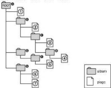
flowchart
graph TD
    A["Receipt"] --> B["1"]
    B --> C["2"]
    C --> D["3"]
    D --> E["4"]
    E --> F["5"]
    F --> G["6"]
    G --> H["7"]
    H --> I["8"]
    I --> J["9"]
    J --> K["10"]
    K --> L["11"]
    L --> M["12"]
    M --> N["13"]
    N --> O["14"]
    O --> P["15"]
    P --> Q["16"]
    Q --> R["17"]
    R --> S["18"]
    S --> T["19"]
    T --> U["20"]
    U --> V["21"]
    V --> W["22"]
    W --> X["23"]
    X --> Y["24"]
    Y --> Z["25"]
    Z --> AA["26"]
    AA --> AB["27"]
    AB --> AC["28"]
    AC --> AD["29"]
    AD --> AE["30"]
When you insert a DATA CD and press I=>, the numbered tracks are played sequentially, from ① through ②. Any sub-albums/tracks contained within a currently selected album take priority over the next album in the same tree. (Example: ③ contains ④ so ⑤ is played before ⑥.)
When you press a RETURN and the list of MP3 albums appears (page 86), the albums are arranged in the following order: A → B → C → D → F → G
Albums that do not contain tracks (such as album E) do not appear in the list.
continued
Playing an MP3 audio track
37
Tips
- If you add numbers (01, 02, 03, etc.) to the front of the track file names, the tracks will be played in that order.
- A disc with many trees takes longer to start playback. Some discs with many trees cannot be played back.
Notes
- D e p e nding on the software you use to create the DATA CD, the playback order may differ from the illustration above.
- The playbook order above may not be applicable if there are more than a total of 200 albums and tracks in the DATA CD.
- The player can recognize up to 100 albums (the player will count just albums, including albums that do not contain MP3 audio tracks). The player will not play any albums beyond the first 100 albums. Of the first 100 albums, the player will play no more than a combined total of 200 albums and tracks.
Playing JPEG image files DATA-CD
You can play JPEG image files on DATA CDs (CD-ROMs/CD-Rs/CD-RWs).
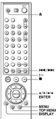
1

Press ▲ and place a DATA CD on the disc tray, then press ▲ to close the tray.
When you load a DATA CD which contains MP3 audio tracks and JPEG image files, "Sélectionnez le type de media" menu appears.
If you load a DATA CD which contains only JPEG image files, the "Album" display appears. Then you can skip step 2.
2

Press ♦/♦ to select "JPEG", then press ENTER.
The "Album" display will appears. If you do not press ENTER after selecting a media type, the selected media will be automatically played.
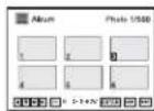
88
Playing an MP3 audio track
3

Press ◄◀/▶▶ to select the next/previous album page, then press ♦/♦/♦/♦ to select an image in the "Album" display.

To display the selected image
1 Press ENTER.
The selected image number appears in the display window.
2 To display the next/previous image, press

To play the Slide show
1 Press =>.
You can also play the Slide show using the menu on the selected image.
For details, see "To enjoy the Slide show" on page 91.
2 Press ◆/◆ to select the desired playing speed on the "Intervalle" menu, then press ENTER.
Slide show starts from the selected image.
2 Press ◆/◆ to select the desired playing speed on the "Intervalle" menu, then press ENTER.
Slide show starts from the selected image.
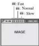
To rotate an Image
1 Press ♦/♦/♦/♦ to select an image in the "Album" display, then press ENTER.
2 Press ♦/♦ to select “☐”, then press ENTER. Each time you press ENTER, the image turns clockwise by 90°.
To zoom in an image
1 Press +/+/*/ to select an image in the "Album" display, then press ENTER.
2 Press ♦/♦ to select "■", then press ENTER.
"■" a appears.
3 Press ♦/♦/♦/♦ to move “■” to the position where you want to zoom in.
4 Press ENTER repeatedly to change the magnification. Each time you press ENTER, the magnification changes as shown below.
2. → normal magnification
continued
Playing JPEG image files
89
To enjoy the Slide show
1 Press ♦/♦/♦/♦ to select an image in the "Album" display, then press ENTER.
2 Press ✦/✗ to select “✗”, then press ENTER. The “Intervalle” menu appears.
3 Press ♦/♦ to select the desired playing speed, then press ENTER.
Slide show starts.
To turn on/off the menu in the single image display
Press DISPLAY in the single image display.
To return to the "Album" display
Press DISPLAY to turn on the menu and press ◆/→ to select “■”, then press ENTER. You can also use MENU button to return to the “Album” display. Press I◀◀ repeatedly to return to the first “Album” page.
• S | i d e show can play in only one direction.
- You can not rotate or zoom in the image during Slide show.
- If you select "■" in the rotated image display, the images in the "Album" display will also be rotated. Correct the rotation in the single image display.
About JPEG Image files
You can play JPEG image files on CD-ROMs, CD-Rs, or CD-RWs. However, the discs must be recorded according to ISO9660 level 1, level 2, or Joliet format for the player to recognize the files.
You can also play discs recorded in Multi Session.
See the instructions of the CD-R/RW device or recording software (not supplied) for details on the recording format.
To play a Multi Session CD
This player can play Multi Session CDs when an JPEG image file is located in the first session. Any subsequent JPEG image files, recorded in the later sessions, can also be played back. When audio tracks and images in music CD format or video CD format are recorded in the first session, only the first session will be played back.
90
Playing JPEG image files
continued
Playing JPEG image files
91
Tip
- If you add numbers (01, 02, 03, etc.) to the front of the file names, the files will be played in that order.
Notes
- The system can play the extension "JPG" or "JPEG".
- Some CD-Rs or CD-RWs cannot be played on this system depending on file format.
- If you add the extension "JPG" or "JPEG" to data not in JPG format, the display will be
blank. - D e p erding on the disc or the size of image files, playback may take some time to start.
Playing VIDEO CDs with "MENU OUI/NON" functions VCD
The PBC (Playback control) function allows you to search and perform other operations interactively. PBC playback follows a selection menu displayed on your TV screen. The "MENU OUT" function is the PBC function.
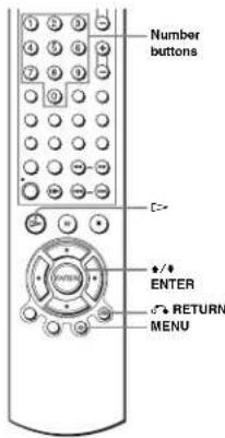
1
Start playing a VIDEO CD with "MENU OUT". The menu for your selection appears.
2
Press ♦/♦ to select the item number you want. You can also use the number buttons to select the item number and track.
continued
Playing VIDEO CDs with "MENU OUI/NON" functions
3

Press ENTER.
4
Follow the instructions in the menu for interactive operations.
Refer to the instructions supplied with the disc, as the operating procedure may differ depending on the VIDEO CD.
To return to the menu
Press ⬆ RETURN.
To play using "MENU NON"
Press MENU to select "MENU NON".
When "MENU NON" is selected, the DVD player starts continuous play. You cannot
play still pictures such as a menu.
To return to "MENU OUI", press MENU to select "MENU OUI".
Tip
e p e nding on the VIDEO CD, "Press ENTER" in step 3 may appear as "Press SELECT" in the instructions supplied with the disc. In this case, press E=>.
VCR Additional Operations
Playing a tape with SQPB function VHS
The SQPB (Super VHS Quasi Playback) function is only for playing a Super VHS format tape.
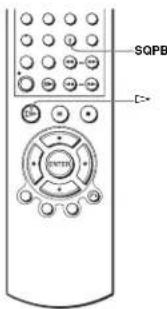
1
Insert a Super VHS format tape.
2

Press [=>
3
ANGLE

Press SQPB to start SQPB.
Notes
- Y on cannot use the SOPB function for recording.
- T he playback display will be distorted if you use the SQPB function with a normal VHS format tape.
- When you eject the tape, the VCR automatically returns to normal mode.
- Playback of tapes recorded in EP (Extended Play) mode on an NTSC system is not guaranteed.
Quick Timer Recording VHS
After you have started recording, you can have the VCR stop recording automatically after a specified duration.
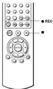
1

While recording, press ● REC.
2

Press ● REC repeatedly to set the duration time. In SP mode
Each press advances the time in increments of 30 minutes.

In 1.2 mode
Each press advances the time as shown below.
→ 0:30 4:00 → 8:00 9:00 → Normal recording
The tape counter decreases minute by minute to 0:00, then the VCR stops recording.
96
Quick Timer Recording
Recording stereo and bilingual programmes VHS
In the ZWEITON (German stereo) system
This VCR automatically receives and records stereo and bilingual programmes based on the ZWEITON system. When a stereo or bilingual programme is received, the STEREO indicator appears in the display window.
To select bilingual sound while recording
Press AUDIO to select the sound you want.
To listen to On-screen display Display window
| Main | PRINCIPALE | STEREO |
| Sub SECONDAIRE STEREO | ||
| Main and sub | PRINCIP/SEC. STEREO | |
| Standard sound * | MONO | STORTO |
• Usually the main channel heard from both the left and right in bilingual programmes
To select stereo programme while recording
To listen to On-screen display Display window
| Stereo | STERFO | STERFO |
| Left channel | CANAL G | STERFO |
| Right channel | CANAL D | STERFO |
| Standard sound • | CANAL G + CANAL D | STERFO |
- Usually the mixed sound of left and right channels in stereo programmes
In the NICAM system
This VCR receives and records stereo and bilingual programmes based on the NICAM system (NICAM appears on the TV screen). When a stereo or bilingual programme is received, the STEREO indicator appears in the display window.
To record a NICAM programme, "NICAM" in the "REGLAGES UTILISATEUR" menu should be set to "Oui" (initial setting). To check the menu setting, see page 110 for details.
98
Recording stereo and bilingual programmes
To extend the duration
Press ● REC repeatedly to set a new duration time.
To cancel the duration
Press ● REC repeatedly until the ○ indicator disappears and the VCR returns to normal recording mode.
To stop while recording
Press ■.
Note
- You cannot display the current tape time in the display window when setting the recording duration time.
Quick Timer Recording
97
To select the sound while recording
Press AUDIO to select the sound you want.
Stereo programmes
| To listen to On-screen display Display window | ||
| Stereo | NICAM, STEREO | STEREO |
| Left channel | NICAM, CANAL G | STEREO |
| Right channel NICAM, CANAL D | STEREO | |
| Left and right channels + | NICAM, CANAL G +CANAL D | STEREO |
- Usually the mixed sound of left and right channels
Bilingual programmes
| Tolisten to On-screen display Display window | ||
| Main | NICAM, PRINCIPALIE | STEREO |
| Sub NICAM, SECONDAIRE | STEREO | |
| Main and sub | NICAM, PRINCIPI/SEC | STEREO |
| Standard sound + | NICAM, MONO | STEREO |
• Usually the main sound (monatral)
Selecting the sound during HI-fl playback
Press AUDIO to select the sound you want.
To listen to On-screen display Display window
| Stereo | STEREO | STEREO |
| Left channel | CANAL G | STEREO |
| Right channel CANAL D | STEREO | |
| Mix sound + | MIX | STEREO |
| Mono sound | MONO | No indicator |
- The mixed sound of left and right channels, and the normal mono audio track
continued
Recording stereo and bilingual programmes
99
How sound is recorded on a video tape
The VCR records sound onto two separate tracks. Hi-fi audio is recorded onto the main track along with the picture. Monaural sound is recorded onto the normal audio track along the edge of the tape.
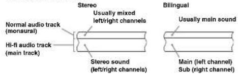
Notes
- To listen to playback sounds in stereo, you must use the PERITEL or AUDIO OUT connections.
- When you play a tape recorded in monaural, the sound is heard in monaural regardless of the AUDIO setting.
Searching using index function VHS
The VCR automatically marks the tape with an index signal at the point where each recording begins. Use these signals as references to find a specific recording.
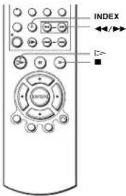
To find a specific recording by scanning (Index scan)
1 Insert an indexed tape into the tape compartment.
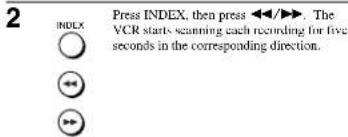
3 Press <> to start playback when you find the desired point.
VCR Additional Operations
100
Recording stereo and bilingual programmes
continued
Searching using index function
101
To search a specific recording (Index search)
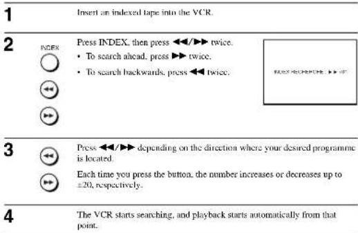
To stop searching
Press ■
Note
N o index signal will be added when recording starts from recording pause. However, an index signal will be marked if you change the programme position during recording pause.
Adjusting the picture (tracking) VHS
Adjusting the tracking
Although the VCR automatically adjusts the tracking when playing a tape, distortion may occur if the recording is in poor condition. In this case, manually adjust the tracking.
During playback, press TRACKING +/- to display the tracking meter. The distortion should disappear as you press one of the two buttons. To resume automatic tracking adjustments, eject the tape and re-insert it.
Adjusting the picture
sharpness (Smart trilogic)
You can automatically adjust the sharpness of the picture.
Tracking meter
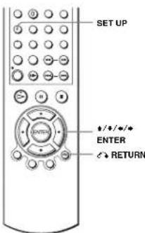
1 SET UP During playback, press SET UP, then press
↑/↓ to select (OPTION) and press ENTER.

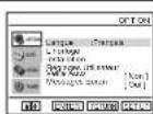
VCR Additional Operations
102
Searching using index function
continued
Adjusting the picture (tracking)
103
2

Press ♦/♦ to select "Réglages Utilisateur", then press ENTER.
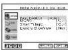
3

Press ♦/♦ to select "Smart Trilogic", then press ♦.
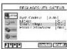
4

Press ♦/♦ to set "SMART TRILOGIC" to "OUT" or "NON".
- OUT: Picture sharpness is automatically adjusted.
• NON: Adjust the picture sharpness manually.
To soften the picture, press ♦
To sharpen the picture, press ♦.
5

Press 📞 RETURN to return to the original screen.
104
Adjusting the picture (tracking)
3

Press ♦/♦ to change the setting.
SET UP
Press SET UP to exit the menu.
Menu choices
The default settings are indicated in bold print.
OPTION
| Menu option Set this option to | |
| Ville Auto | • "Non" to deactivate the Auto Power Off function. • "1Heures"/21Heures"/31Heures" to turn the DVD-VCR off automatically if no signal is received and you do not press any of the buttons during this time. |
| Messages Ecran | • "Oul" to display the menu on the TV screen. • "Non" to disappear the menu from the TV seconds. |
VIDEO SETUP
| Menu option Set this option to | |
| Select. Cassette | • "E180" to use an E-180 or shorter type tape. • "T 2 4 0 " to use an E-240 type tape. • "E 2 6 0 " to use an E-290 type tape. • "T 3 0 0 " to use an E-300 type tape. |
| Répétion Torale • "Oui" to play back a tape repeatedly. The VCR rewinds a tape to fix: beginning and restarts playback automatically. • "Non" to turn off Auto repeat. | |
106
Changing menu options
Changing menu options VHS
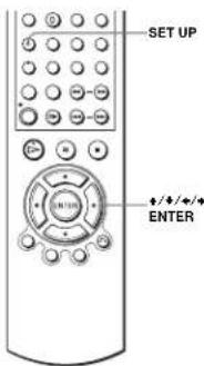
1

Press SET UP when the DVD player is in stop
mode, then press ♦/♦ to select
(OPTION) or VIDEO and press
UNIT
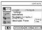

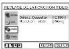
How to connect to record on this VCR
Connect the line outputs of the other VCR to the input connector of this VCR. Refer to the examples A through C and choose the connection that best suits your VCR.
Example A
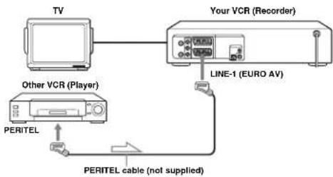
flowchart
graph TD
    A["TV"] --> B["Your VCR (Recorder)"]
    B --> C["LINE-1 (EURO AV)"]
    C --> D["PERITEL"]
    D --> E["Other VCR (Player)"]
    E --> F["PERITEL cable (not supplied)"]

: Signal flow
Example B
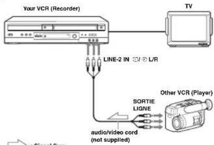
flowchart
graph TD
    A["Your VCR (Recorder)"] --> B["TV"]
    B --> C["Other VCR (Player)"]
    C --> D["sortie Ligne"]
    D --> E["audio/video cord (not supplied)"]
    E --> F["LINE-2 IN ☐/ ⊗ L/R"]
    F --> A

: Signal flow
continued
Editing
107
Example C
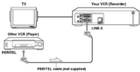
flowchart
graph TD
    TV["TV"] --> Record["Your VCR (Recorder)"]
    Record --> LINE3["LINE-3"]
    LINE3 --> PerITEL["PERITEL"]
    PerITEL --> OtherVCP["Other VCR (Player)"]
    OtherVCP --> TV
    PerITEL -->|PERITEL cable (not supplied)| Line3

: Signal flow
How to connect to a stereo system
Connect the LINE-2 IN →/→ L/R jacks on this DVD-VCR to the audio output jacks on the stereo system, using an audio cable (not supplied).
Notes
• M-ake sure you connect the plugs to jacks of the same colour.
- If the other VCR is a monaural type, leave the red plugs unconnected.
- If you connect this VCR to both the LINE IN and LINE OUT jacks of the other VCR, select
the input correctly to prevent a burning noise.
- When you connect another VCR to the LINE-3 or LINE-2 connector, press INPUT SELECT to display "L3" or "L2" in the display window.
108
Ediling
Additional Information
General setup information
Changing setup options
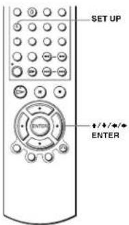
1
SET UP

Press SET UP when the DVD player is in stop mode, then press ♦/♦ to select (OPTION) and press ENTER.
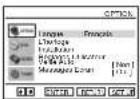
2

Press ♦/♦ to select "Réglages Utilisateur", then press ENTER. The "REGLAGES UTILISATEUR" menu appears.
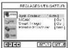
3

110
General setup information
Operation (when recording on this VCR)
Before you start editing
- Turn on your TV and set it to the video channel.
- Press INPUT SELECT to display the connected line in the display window.
- Press SP/LP to select the tape speed, SP or LP.
- Press SELECT VIDEO to control the VCR.
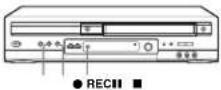
1
Insert a source tape with its safety tab removed into the other (playback) VCR. Search for the point to start playback and set it to playback pause.
2

Insert a tape with its safety tab in place into this (recording) VCR. Search for the point to start recording and press Ⅲ to set it to playback pause.
3

Press ● REC on this VCR to set it to recording pause.
4

To start editing, press the Ⅲ (pause) buttons on both VCRs at the same time.
To stop editing
Press the ■ (stop) buttons on both VCRs.
Tip
- To cut out unwanted scenes while editing, press III on this VCR when an unwanted scene begins. When it ends, press III again to resume recording.
Editing
109
4

Press ◆/◆ to change the setting.
5

Press SET UP to exit the menu.
Menu choices
Initial settings are indicated in bold print.
| Menu option Set this option to | |
| Syst Couleur | • "Auto" to select the colour system automatically. • "P A 1." to use the tape recorded in the PAL colour system. • "S E C A M " to use the tape recorded in the SBCAM system. • "MFSICAM" to use the tape recorded in the MFSICAM colour system. • "B / W" to use the tape recorded in black and white. When using the tape recorded NTSC colour signals. • "NTPB" to play back an NTSC recorded tape on PAL TV. • "N T 4 43" to play back an NTSC-recorded tape on Mte |
| NICAM | • "Oul" to record NICAM broadcasts on the hi-fi audio track. • "N on" to record standard sound on the hi-fi audio track. For details, see page 98. |
| Smart Trilogic | • "Oul" to automatically adjust the sharpness of the picture. • "N on" to manually adjust the sharpness of the picture. |
| Elenize ShowView | • "Non" to deactivate the ShowView Extend function. • 1020W3W..60 (minutes) to extend the time of the ShowView setting by the selected amount of time. |
Troubleshooting
If you have any questions or problems not covered below, please consult your nearest Sony service facility.
General Troubleshooting
| Symptom Remedy | ||
| Power | The I/ (on/standby) switch does not function. | • C on next the mains lead to the mains securely. |
| The power is turned on but the DVD-VCR does not operate. | • M moisture condensation has occurred. Turn the power off, unplag the mains lead and leave the DVD VCR to dry for over three hours. | |
| Clock | The clock has stopped and "-" appears in the display windows. | • T h e clock stops if the DVD-VCR is disconnected from the mains. Reset the clock (and linear). |
| Others | The remote commander does not function. | • M also sure you are pointing the remote commander at the remote sensor on the DVD-VCR. R e p lace all the batteries in the remote commander will new ones if they are weak. • M also sure the TV DVD-VIDEO switch is set correctly. • S elect correctly VIDEO or DVD with the SELF DIVE VIDEO button. |
| The tracking tracker does not appear on the screen. | • T he recording condition of the tape is very poor and tracking cannot be adjusted. | |
| You cannot control other TVs. | • Set your TV's code number. The code number may change when you replace the batteries of the remote commander. |
DVD Troubleshooting
| Symptom Remedy | ||
| Picture | There is no picture/picture noise appears. | R e connect the connecting cord securely.T he connecting cords are damaged.C h c k t h e c o n c t i o n to your TV (page 11) and switch the input selector on your TV so that the signal from the player appears on the TV screen.T h e disc is dirty or flawed.I f the picture output from your player goes through your VCR to get to your TV or if you are connected to a combination TV/VIDEO player, the copy-protection signal applied to some DVD programmes could affect picture quality. If you still experience problems even when you connect your player directly to your TV, please try contacting your player to your TV's S VIDEO input (page 61). |
| Symptom Remedy | ||
| Picture | Even though you set the aspect ratio in "Type TV" of the "REGLAGE DE L'ECLAN" menu the picture does not fill the screens. | • The aspect ratio of the disc is fixed on your DVD. |
| Sound | There is no picture from your VCR connected to the LINE IN jacks. | • The DVD player must be in standby mode to view pictures from your VCR. |
| There is no sound. • Re-connect the connecting card securely.• The co-necting card is damaged.• The p1 ayer is connected to the wrong input jack on the amplifier (receiver) (page 59).• The a m plifier (receiver) input is not correctly set.• The player is in pause mode or in Slow motion Play mode.• The player is in fast forward or fast reverse mode.• If the audio signal does not come through the DIGITAL AUDIO OUT (OPTICAL or COAXIAL) jack, check the audio settings (page 62). | ||
| Soutad is assay. • When playing a CD with DTS sound tracks, noise will come from the OUT AUDIO LR jacks (page 33) or DIGITAL OUT (OPTICAL or COAXIAL) jack. | ||
| The sound volume is low. | • The sound volume is low on some DVDs. The sound volume may improve if you set "Audio DRC" to "TV" (page 61). | |
| Operation | The disc does not play. • The disc is turned over.• I insert the disc with the playback side facing down on the disc tray.• The disc is skewed.• The p1 ayer canns play certain discs (page 6).• The region code on the DVD does not match the player.• Mo i stare has condensed inside the player.• The p1 ayer cannot play CD-Rs, CD-RWs, DVD-Rs or DVD RWs that are not finished (page 7).• M ate sure the TV DVD/VIDEO switch is set correctly.• Select correctly VIDEO or DVD with SELHCT DVD/VIDEO button. | |
| The MP3 audio track cannot be played (page 85). | • The DATA CD is not recorded in the MP3 format that conforms to ISO9600 Level I/Level 2 or Joielet.• The MP3 a audio track does not have the extension "MP3".• The data is not formatted in MP3 even though it has the extension "MP3".• The data is not MPEG1 Audio Layer 3 data.• The player cannot play audio tracks in MP3PRO format. | |
| The JPEG image file cannot be played. | • The DATA CD is not recorded in JPEG conform to ISO9600 Level I/Level 2 or Joielet.• The JPEG image file does not have the extension "JPEG" or "JPEG".• The data is not formatted in JPEG even though it has the extension "JPEG" or "JPEG".• Long ta or width of the image is more than 4720 dots. |
112
Troubleshooting
continued
Troubleshooting
113
| Symptom Remedy | ||
| Operation | The title of the MP3 audio album or track is not correctly displayed. | • The player can only display numbers and alphabet. Other characters are displayed as asterisks. |
| The disc does not start playing from the beginning. | • P r ogramme play, shuffle play, or repeat play, has been selected (pages 78, 80, 81);• R e s u m e play has taken effect (page 32). | |
| The player starts playing the disc automatically. | • T h e disc features an auto playbook function. | |
| Playback stops automatically. | • While playing discs with an auto pause signal, the player stops playback at the auto pause signal. | |
| You cannot perform some functions such as stop, search, slow-motion play, repeat play, shuffle play, or programme play. | • D spending on the disc; you may not be able to do some operations. See the operating manual that comes with the disc. | |
| The language for the sound track cannot be changed. | • T r y u s i ng the DVD's menu instead of the direct selection button on the remote (page 72).• M u l r i lingual tracks are not recorded on the DVD being played.• T h e D VD prohibits the changing of the language for the sound track. | |
| The subtitle language cannot be changed or turned off. | • T r y u s i ng the DVD's menu instead of the direct selection button on the remote (page 73).• M u l t i lingual subtitles are not recorded on the DVD being played.• T h e D VD prohibits the changing of the subtitles. | |
| The angles cannot be changed. | • Try using the DVD's menu instead of the direct selection button on the remote (page 73).• M u l t i -angles are not recorded on the DVD being played.• T h e D VD prohibits changing of the angles. | |
| The player does not operate properly. | • When static electricity, etc., causes the player to operate abnormally, mapping the player. |
VCR Troubleshooting
| Symptom Remedy | ||
| Playback | The playback picture does not appear on the TV screen. | • M: take sure the TV is set to the channel for the VCR. If you are using a monitor, set it to video input. • If the VCR is connected to the TV with the PERITEL cable, make sure the VCR indicator is lit in the display window. Use the TV/VIDEO button on the remote commander to light up the VCR indicator. |
| The picture is not clear | • Adjust the tracking with the TRACKING +/- buttons. • The v i deo heads are dirty (see the last page of Troubleshooting). Clean the video heads using a Sony video head cleaning cassette. If a Sony cleaning cassette is not available in your area, have the heads cleaned at your nearest Sony service facility (as standard service charge will be required). Do not use a commercially available liquid type cleaning cassette either than Sony's, as it may damage the video heads. • The video heads may have to be replaced. Consult your local Sony service facility for more information. | |
| The picture has no colour | • The "Syst. Coulcam" option in the "RECLAGES UTILISATEUR" menu is set to the wrong position. Set the option to confera to the system that the tape was recorded in. | |
| The picture rolls vertically during picture search. | • A d j ut the vertical hold control on the TV or monitor. | |
| The picture has no sound. • The tape is defective. • If you made A/V connections, check the audio cord connection. | ||
| The sound from a tape recorded with the VCR is not in stereo or the STEREO indicator in the display window is Hashung. | • A d j ut the tracking. • The v i deo heads are dirty. Clean the video heads using a Sony video head cleaning cassette as explained above. | |
| Recording | No TV programme appears on the TV screen. | • M: take sure the TV is set to the video channel. If you are using a monitor, set it to video input. • Select the correct source with the INPUT SELECT button. Select a programme position when recording TV programmes; select a line input when recording from other equipment. |
| TV reception is poor. | • Make sure the aerial cable is connected socially. • A d j ut the TV aerial. • Makes sure "SYS. (I.I. or BIG)" in the "RECHIC MANUELLE" menu is set to the same system in your local area. | |
| The tape starts playing as soon as it is inserted. | • The safety tab has been removed. To record on this tape, cover the tab hole. | |
| The tape is ejected when you press ● REC. | • The safety tab has been removed. To record on this tape, cover the tab hole. | |
| Nothing happens when you press ● REC. | • M: take sure the tape is not at its end. | |
114
Troubleshooting
continued
Troubleshooting
115
| Symptom Remedy | ||
| Timer recording | The timer does not operate. • Check that the clock is set.• M . also sure a tape has been inserted.• C . check t h at the safety tab has not been removed.• M . also sure the tape is not at its end.• M . also sure a programme has been set for timer recording.• M . make sure your timer settings are past the current time.• C . check that the decoder is turned on.• C . check t h at the satellite timer is turned on.• T . o clock stops if the DVD-VCR is disconnected from the mains for more than one minute. Reset the clock and timer.• T u r n the power off and unplug the mains lead. | |
| The VPS/PDC function does not operate properly. | • C . check that the clock and the date are set correctly.• C . check t h at the VPS/PDC (time you set is the correct one (there might be a mistake in the TV programme guide). If the broadcaster you wanted to record did not send the good VPS/PDC information, the VCR will not start recording.• I f t h e reception is poor, the VPS/PDC signal might be altered and the VCR might not start recording. | |
| Canal Plus | You cannot watch Canal Plus programmes when the VCR is in standby mode. | • C . check t h at "DEC" is set to "OUI" for this channel in the "LISTE STATIONS TV" menu.• M . also sure the Canal Plus PERITEL cable is plugged securely. |
| A Canal Plus programme is always recorded scrambled. | • M . also sure the Canal Plus PERITEL cable is plugged securely.• C . check t h at "DEC" is set to "OUI" for this channel in the "LISTE STATIONS TV" menu. | |
| Others | A tape cannot be inserted. • Check that a tape is not already in the tape compartment. | |
| The selected input line connector number does not appear in the display window. | • P . c . ss INPUT SELECT to display the connected line. | |
| The VCR mechanism needs to be cleaned. | • C lean the cabinet, panel and controls with a dry, soil cloth, or a soft cloth slightly moistened with a mild detergent solution. Do not use any type of solvent, such as alcohol or benzine. | |

Symptoms caused by contaminated video heads
• Rough picture
- Unclear picture
• No picture (or


initial contamination
116
Troubleshooting
Title (page 35)
The longest section of a picture or music feature on a DVD, movie, etc., in video software, or the entire album in audio software.
Track (page 35)
Sections of a picture or a music feature on a CD or VIDEO CD (the length of a sung).
118
Glossary
Glossary
Chapter (page 35)
Sections of a picture or a music feature that are smaller than titles. A title is composed of several chapters. Depending on the disc, no chapters may be recorded.
Dolby Digital (pages 60 and 63)
Digital audio compression technology developed by Dolby Laboratories. This technology conforms to 5.1-channel surround sound. The rear channel is stereo and there is a discrete subwoofer channel in this format. Dolby Digital provides the same 5.1 discrete channels of high quality digital audio found in Dolby Digital cinema audio systems. Good channel separation is realized because all of the channel data are recorded discretely and little deterioration is realized because all channel data processing is digital.
Dolby Surround (Pro Logic) (page 59)
Audio signal processing technology that Dolby Laboratories developed for surround sound. When the input signal contains a surround component, the Pro Logic process outputs the front, centre and rear signals. The rear channel is monaural.
DTS (page 63)
Digital audio compression technology that Digital Theater Systems, Inc. developed. This technology conforms to 5.1-channel surround sound. The rear channel is stereo and there is a discrete subwoofer channel in this format. DTS provides the same 5.1 discrete channels of high quality digital audio.
Good channel separation is realized because all of the channel data is recorded discretely and little deterioration is realized because all channel data processing is digital.
DVD (page 6)
A disc that contains up to 8 hours of moving pictures even though its diameter is the same as a CD.
The data capacity of a single-layer and single-sided DVD is 4.7 GB (Giga Byte), which is 7 times that of a CD. The data capacity of a double-layer and single-sided DVD is 8.5 GB, a single-layer and double-sided DVD is 9.4 GB, and double-layer and double-sided DVD is 17 GB. The picture data uses the MPEG 2 format, one of the worldwide standards of digital compression technology. The picture data is compressed to about 1/40 (average) of its original size. The DVD also uses a variable rate coding technology that changes the data to be allocated according to the status of the picture. Audio information is recorded in a multi-channel format, such as Dolby Digital, allowing you to enjoy a more real audio presence.
Furthermore, various advanced functions such as the multi-angle, multilingual, and Parental Control functions are provided with the DVD.
DVD-RW (page 6)
A DVD-RW is a recordable and rewritable disc that is the same size as a DVD VIDEO. The DVD-RW has two different modes: VR mode and Video mode. DVD-RWs created in Video mode have the same format as a DVD VIDEO, while discs created in VR (Video Recording) mode allow the contents to be programmed or edited.
DVD+RW (page 6)
A DVD+RW (plus RW) is a recordable and rewritable disc. DVD+RWs use a recording format that is comparable to the DVD VIDEO format.
continued
Glossary
117
Index to parts and controls
Refer to the pages indicated in parentheses ( ) for details.
Front panel
SLV-D950B
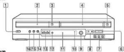
SLV-D910B
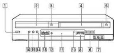
[1]I/ (on/standby) switch (10) (38)
|2|Disc tray (31)
③合 (open/close) button (31) (32)
④ Tape compartment (37)
5△ (eject) button (38)
6 SELECT DVD/VIDEO (9)
7 LINE-2 IN ⊖l→L/R jacks ^61 (107)
8|PROGRAM +/- buttons ^2 (11)
9 DIAL TIMER* (52)
10 Remote sensor (9)
11 Display window (32) (37)
12 ● REC (record) button (4.1)
13 ◀◀ (rewind)/▶▶ (fast-forward) buttons (33) (38)
14■ (stop) button (32) (38)
15 (pause) button (32) (38)
16 C> (play) button (32) (37)
* Covered
^*2 PROGRAM + button has a tactile dot. Use the tactile dot as a reference when operating the DVD-VCR.
^1 SLV-D950B only
continued
Index to parts and controls
121
Display window
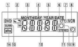
1 DVD indicator (32)
2 Disc indicator (32)
3 MONTH indicator • (52)
4 DAY indicator • (52)
5 YEAR indicator • (52)
6 DATE indicator • (52)
7 Tape indicator (37)
8 VCR indicator (37)
9 Timer indicator (46)
10 Recording indicator (41)
|11|STEREO indicator (98)
12 Playing time/clock/current status
indicator (32)
13 SURR (surround) indicator (83)
|14|DTS indicator (63)
• SLV D950B only
Rear panel
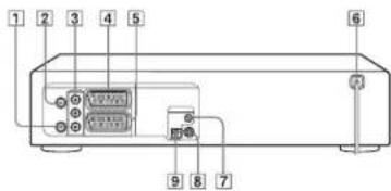
DVD player and VCR
[1] (out to tv) connector (II)
2 (from antenna) connector (11)
3 OUT VIDEO/AUDIO L/R jacks (11) (59)
[4]LINE-3 connector (12)
⑤LINE-1 (EURO AV) connector (11)
DVD player only
|6|Mains lead (11)
⑦ DIGITAL AUDIO OUT jack (COAXIAL) (60)
8S-VIDEO OUT jack (61)
|9|DIGITAL AUDIO OUT jack (OPTICAL) (60)
122
Index to parts and controls
Remote commander for DVD
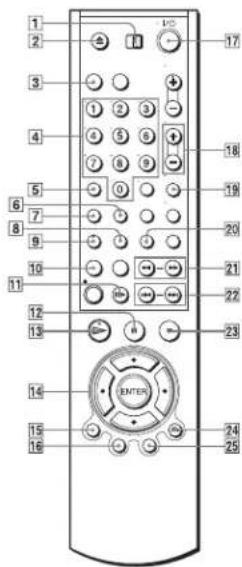
① TV / DVD•VIDEO switch (9)
2 ▲ (open/close) button (31) (32)
3 SELECT DVD button (9)
4 Number buttons * {10} (71)
5 CLEAR button (79)
6 SURROUND button (83)
7SET UP button (14)
8|SUBTITLE button (77)
9 AUDIO button • (82)
10 REPEAT/PROGRAM button (78) (81)
11▶ STEP button (32)
|12| (pause) button (32)
13 ▷ (play) button · (32)
14 ♠/♣/♦/→ buttons
ENTER button (14)
15 DISPLAY button (35) (41)
|16|TOP MENU button (73)
17 I/O (on/standby) switch (10)
18 VOL (volume) = 1 - buttons (10)
19 ZOOM button (75)
20 ANGLE button (76)
21 ◀◀/▶▶ SCAN/SLOW▶ buttons (32)
22 ◀◀/▶▶1 PREV/NEXT buttons (32)
23 ■ (stop) button (32)
24 RETURN button (20)
25 MENU button (73)
- Number 5. AUDIO and [=> buttons have a tactile dot. Use the tactile dot as a reference when operating the DVD-VCR.
Remote commander for VCR
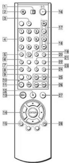
continued
Index to parts and controls
123
① TV / DVD·VIDEO switch (9)
2 ▲ (eject) button (38)
3 SELECT VIDEO button (9)
4 Number buttons * (10)
5 CLEAR button (24)
6SET UP button (14)
7 TIMER button (49)
8 AUDIO button · (98)
9 INDEX button (101)
10 II STEP button (38)
11● RLC (record) button (41)
12 II (pause) button (38)
13 ▷(play) button · (37)
14+/↓/↔buttons
ENTER button (14)
15 DISPLAY button (41)
161/ (on/standby) switch (10) (38)
17 PROG (programme)/TRACKING +/- buttons • (39) (41)
18 VOL (volume) +/- buttons (10)
19-/-- (ten's digit) button (10)
20 MUTING button (10)
21 SP (Standard Play)/L.P (Long Play) button (41)
22TV/VIDEO button (42)
23 SQPB button (95)
24 INPUT SELECT button (41)
25 ← (rewind)/▶ (fast-forward) buttons
SLOW ▶ button (38)
26 |◀◀/▶▶| SHUTTLE buttons (38)
27 ■ (stop) button (38)
28 RETURN button (20)
Number 5, AUDIO, E= and PROG
TRACKING + buttons have a tactile dot. Use the tactile dot as a reference when operating the DVD-VCR
124
Index to parts and controls
Index to parts and controls
125
DVD Audio/Subtitle Language
| Abbreviation Language | |
| ARA Arabic | |
| CHI Chinese | |
| CRO Croatian | |
| CZK Czech | |
| DAN Danish | |
| DEU German | |
| ENG English | |
| ESP Spanish | |
| ITN finish | |
| FRA French | |
| GRE Greek | |
| HUN Hungarian | |
| IDN | 1 n |
| IND Hindi | |
| ISL Icelandic | |
| ITA Italian | |
| IWR Hebrew | |
| JPN Japanese | |
| KOR Korean | |
| MAL Malay | |
| NL D Dutch | |
| NOR Norwegian | |
| POL | Polish |
| POR Portuguese | |
| RUS | Russian |
| SVE Swedish | |
| THA Thai | |
| TUR Turquish | |
| VIE Vietnamese | |
| ZAF Afrikaans | |
donesian
Index
Numerics
16966
4:3 Letter Box 60
4:3 Pan Scnn 66
A
Adjusting
picture 103
tracking 103
Aerial makeup
Angle 70
Audio Back A/O Ave Gisels Box 17
Auto Clock Set 12
C
Canal Plus 27
Changing the programme
position 21
Changing the station name 25
Clock setting 16
Colour system
Commercial Strip 78
Commercial Bank 50 Connecting
Connecting
the 19+13-VC.K and your TV.11
171
to video equipment TO
Counter 39
□
DATA CD 6 85 89
Demonstration Mode 55
Dial Timer 52
Disabling the programme
positions 23
ISOLHY DIGITAL. 59,82
DTS 60.82
DVD 6
E
Editine 107
H
Handling discs?
11i-fi audio track 100
I
Index scan 101
J
JPEG 6.89
L
Language selecting 15
LP mode 41
B
Manual fine tuning 20
Monatral 99
Moulongins
during playback 99
during rounding 98
MP3 6.85
N
NICAM broadcasts 98
Normal audio track 100
F
Parental Control 70
PBC (Playback control) 93
PDC iProgramme Delivery
Control 46
Picture adjustment 103
Playback 31 47
at various events 22-28
from the following: 71
IBEC (many files 80
M17 studio track V5
MI 3 (bio) (Iber 6)
programme play is
repeat play 81
selecting the sound 98,99
shuttle play 80
skip 38
slow motion 33, 38
VIDEOCD<2>
Presetting channels 18
Programme play 78
R
Recording 40
quick timer recording 96
savine 42
using DIAL TIMER 52
using the ShowView
vocum 14
while watching another
esentary: 42, 47, 51
Pereys play 51
The following table
Kochler 30
10
Safety tab 42
Searching
at various speeds 33.38
ShowView
recording 44
Shuffle play 8
Slide show 91
Smart trilogic 193
SP mode41
STEREO 82.08
Subsista 72
T
Timer setting
daily/weekly recording 46.
501
quick timer recording 96
using DIAL TIMER 52
using the ShowView
system 4
Tracking adjustment, see
Adjusting
U
Useable discs 6
y
VIDEO CD 6
VPS (Volco Prestaurine
System) 16
7
Zoom 25:00
ZWEITON broadcasts 98
2. DISASSEMBLY AND REASSEMBLY
2-1 CABINET AND PCB
2-1-1 Cabinet Top Removal 2-1-3 Ass'y Front Panel Removal
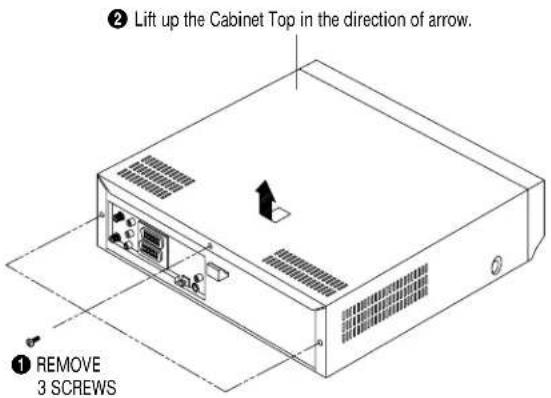
Fig. 2-1 Cabinet Top Removal
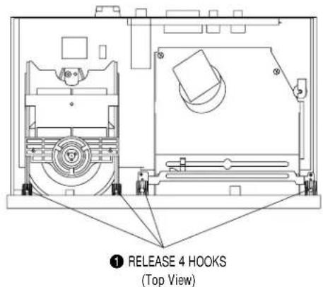
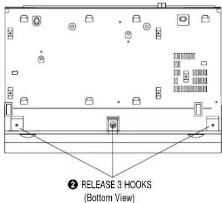
Fig. 2-3 Ass'y Front Panel Removal
2-1-2 Bottom Cover Removal
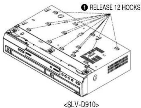
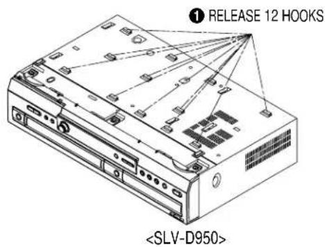
Fig. 2-2 Bottom Cover Removal
2-1-4 Function PCB Removal
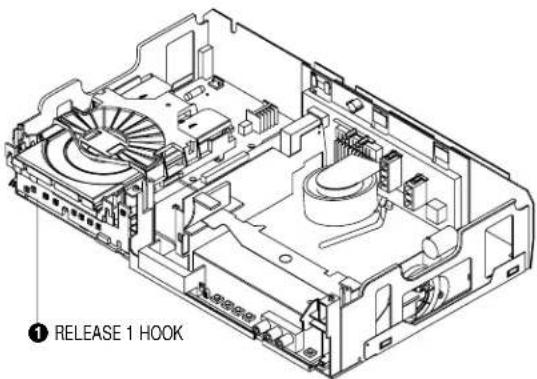
Fig. 2-4 Function PCB Removal
2-1-5 Chassis Removal
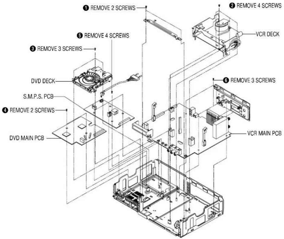
Fig. 2-5 Chassis Removal
2-1-6 VCR Main PCB Removal
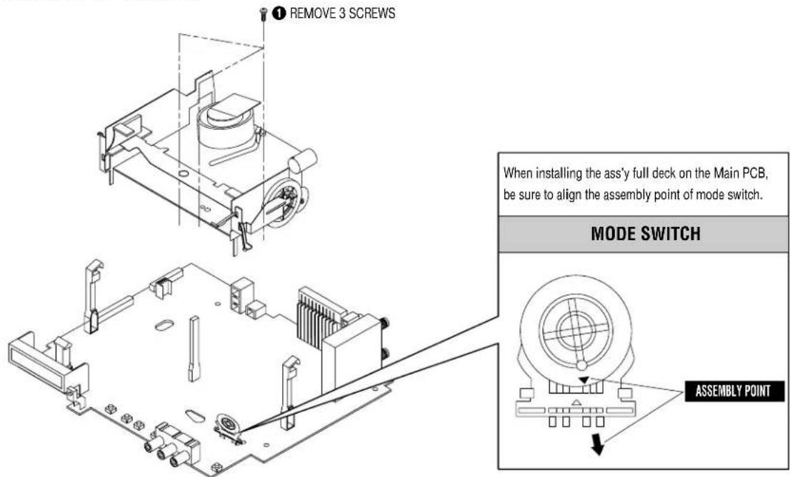
Fig. 2-6 VCR Main PCB Removal
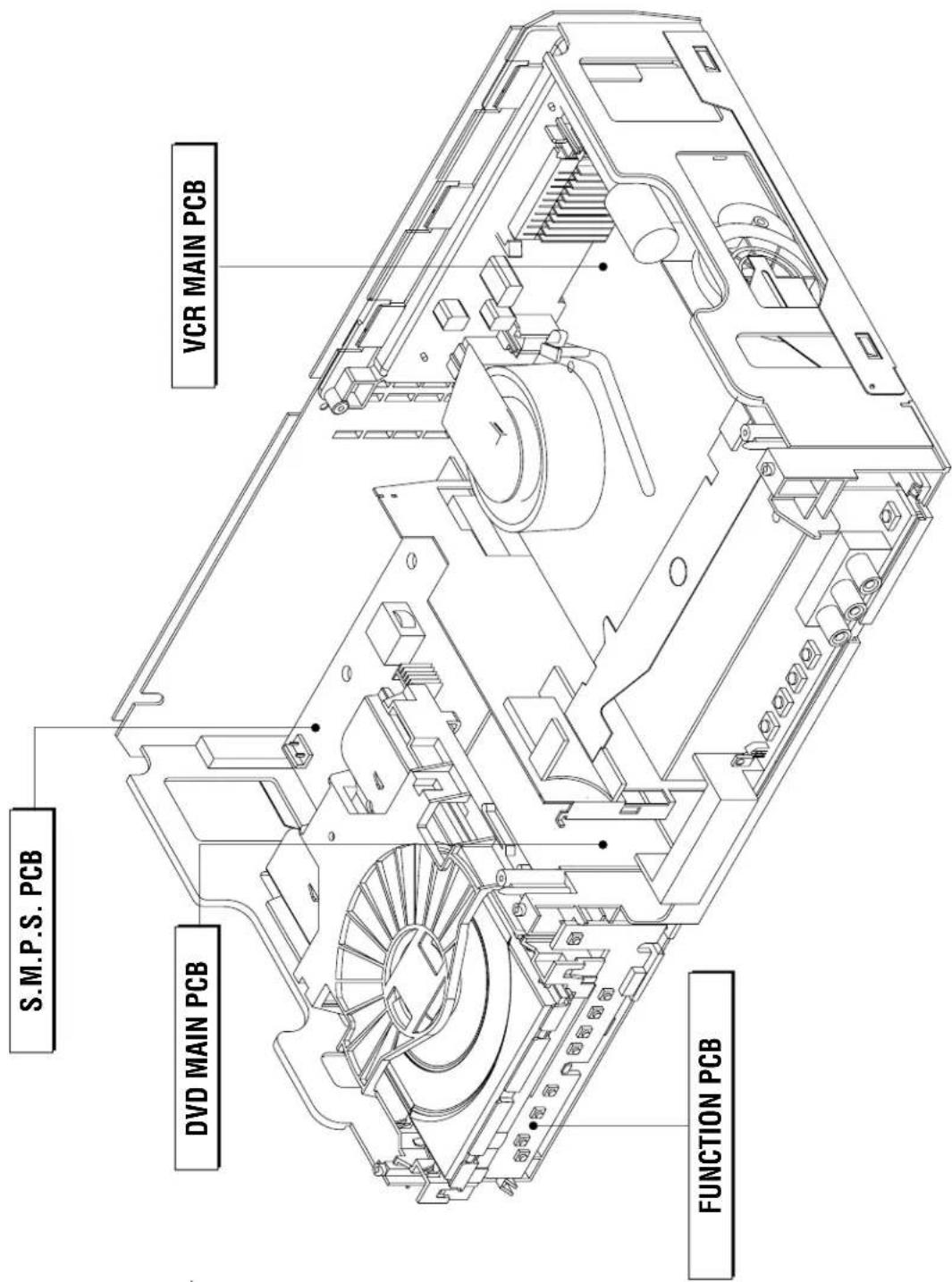
Fig. 2-7 Circuit Board Locations
2-3-1 Top View
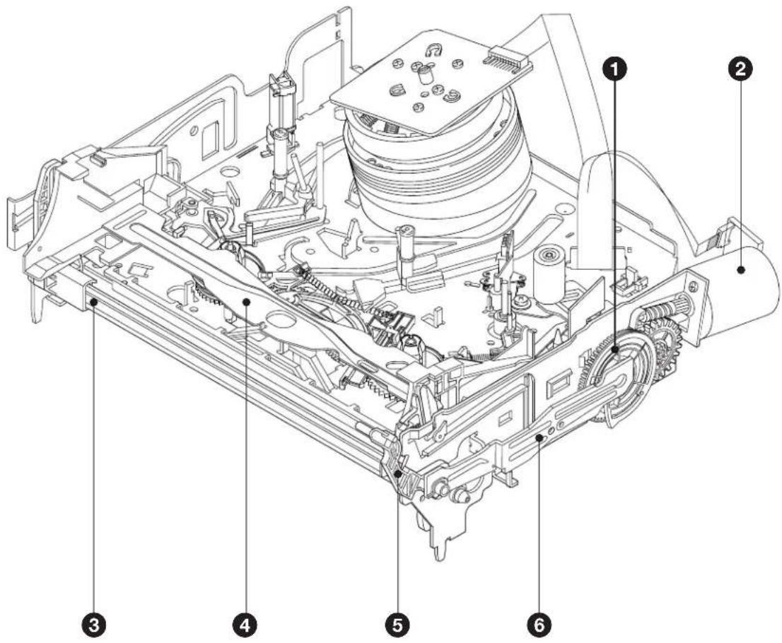
Fig. 2-8 Top parts Location-1
① GEAR FL CAM
②MOTOR LOADING ASS'Y
③ LEVER FL ARM ASS'Y
④HOLDER FL CASSETTE ASS'Y
⑤ LEVER FL DOOR
6 SLIDER DRIVE
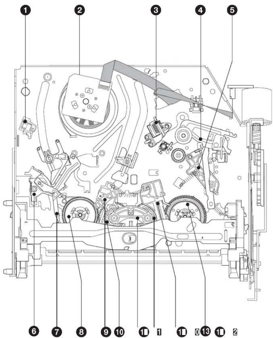
Fig. 2-9 Top Parts Location-2
① FE HEAD
② CYLINDER ASS'Y
③ACE HEAD ASS'Y
④ LEVER UNIT PINCH ASS'Y
⑤ LEVER #9 GUIDE ASS'Y
6 LEVER TENSION ASS'Y
⑦ BAND BRAKE ASS'Y
⑧ DISK S REEL
9 LEVER S BRAKE ASS'Y
10 GEAR IDLE
11 LEVER IDLE
12 LEVER T BRAKE ASS'Y
13 DISK T REEL
2-3-2 Bottom View
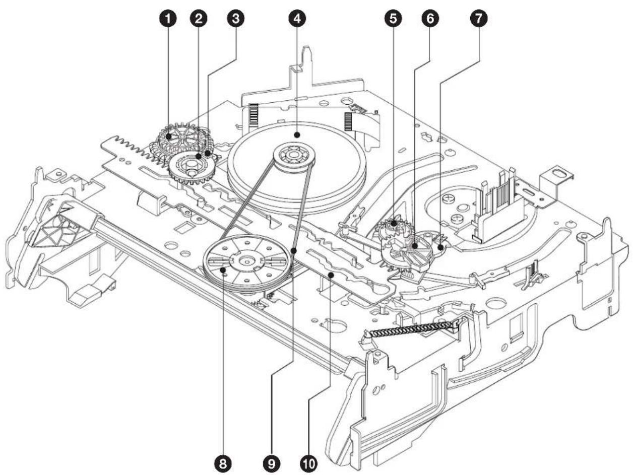
Fig. 2-10 Bottom Parts Location
① GEAR JOINT 1
② GEAR JOINT 2
③BRAKET GEAR
④ MOTOR CAPSTAN ASS'Y
⑤ LEVER T LOAD ASS'Y
⑥ GEAR LOADING DRIVE
7 LEVER S LOAD ASS'Y
8 HOLDER CLUTCH ASS'Y
⑨ BELT PULLEY
10 SLIDER CAM
2-4-1 Holder FL Cassette Ass'y Removal
1) Pull the Holder FL Cassette Ass'y ① to the eject position.
2) Pull the Holder FL Cassette Ass'y ① as grasping the Holder FL Cassette Ass'y ① and Lever FL Cassette-R ② in the same time to release hooking from Main Base until the Boss [A] of Holder FL Cassette Ass'y ① is taken out from the Rail [B].
3) Lift the Holder FL Cassette Ass'y ①, in this time, you have to grasp the Lever FL Cassette-R ② Continuously until the Holder FL Cassette Ass'y ① is taken out completely.
Note: Be sure to insert Lever FL Cassette-R ② in the direction of "A" to prevent separation and breakage of the Lever FL Cassette-R ② at disassembling and reassembling.
![①HOLDER FL CASSETTEE ASS'Y "A" BOSS [A] ②LEVER FL CASSETTEE -R RAIL [B]](/content/2026/05/1017698/images/9ede554ec29448e8178212182d9d3e383a64e8f71099f7c61c15cb31d6ecba6e.jpg)
Fig. 2-11 Holder FL Cassette Ass'y Removal
2-4-2 Lever FL Door Removal
1) Release the Hook ② and Remove the Lever FL Door ① in the direction of arrow "A".
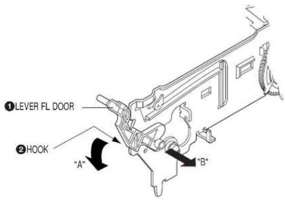
Fig. 2-12 Lever FL Door Removal
2-4-3 Slider FL Drive, Gear FL Cam Removal
1) Pull the Slider FL Drive ① to the front direction.
2) Remove the Slider FL Drive 1 in the direction of arrow. (Refer to Fig. 2-13)
3) Remove the Gear FL cam ②.
Note: When reinstalling be sure to reassemble Slider FL drive 1 after you insert the Boss of Lever FL ARM-R in Groove of Slider FL drive 1.
Assembly: Align the Gear FL Cam ① with the Gear worm wheel Post as shown drawing. (Refer to Timing point)
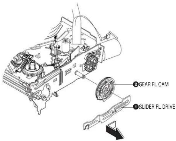
Fig. 2-13 Slider FL Drive Removal
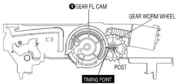
Fig. 2-14 Gear FL Cam, Gear Worm
2-4-4 Lever FL Arm Ass'y Removal
1) Push the hole "A" in the direction of arrow "B" use the pin.(about Dia. 2.5)
2) Pull out the Lever FL Arm Ass'y ① from the Boss of Main Base.
3) Remove the Lever FL Arm Ass'y ① in the direction of arrow "C".
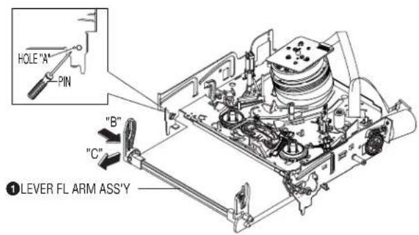
Fig. 2-15 Lever FL Arm Ass'y Removal
2-4-5 Gear Worm Wheel Removal
1) Remove the Gear Worm wheel ①.
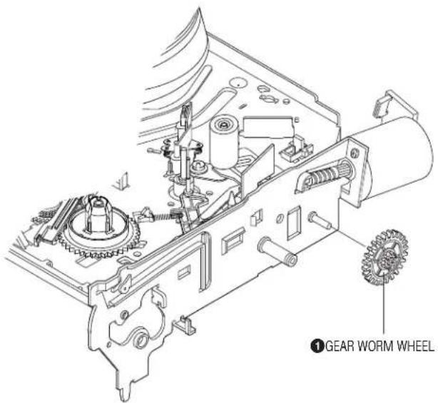
Fig. 2-16 Gear Worm Wheel Removal
2-4-6 Cable Flat Removal
1) Remove the Drum connecting part of Cable Flat ① from Connector Waffer ②.
2) Remove the Loading Motor connecting part of Cable Flat ① from Connector Waffer ③.
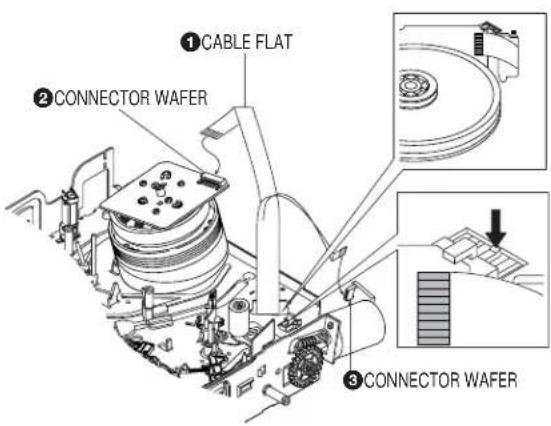
Fig. 2-17 Cable Flat Removal
2-4-7 Motor Loading Ass'y Removal
1) Remove the screw ①.
2) Remove the Motor Loading Ass'y ②.
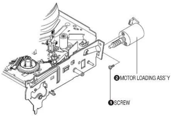
Fig.2-18 Motor Loading Ass'y Removal
2-4-8 Bracket Gear, Gear Joint 2, 1 Removal
1) Remove the SCREW ①.
2) Remove the Bracket Gear ②.
3) Remove the Gear Joint 2 ③.
4) Remove the Gear Joint 1 ④.
Assembly:
1) Be sure to align dot mark of Gear Joint 1 ① with dot mark of Gear Joint 2 ② as shown Fig 2-20.
(Refer to Timing point1)
2) Confirm the Timing Point 2 of the Gear Joint 2 ② and Slider Cam ③.
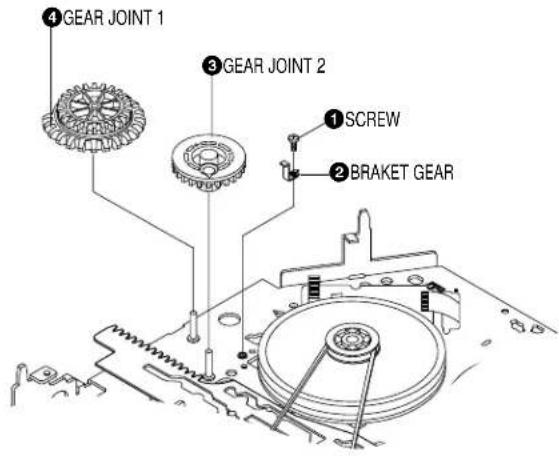
Fig. 2-19 Bracket Gear, Gear Joint 1,2 Removal
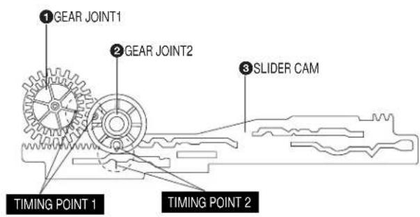
Fig. 2-20 Gear Joint 1,2 Assembly
2-4-9 Gear Loading Drive, Slider Cam, Lever Load S, T Ass'y Removal
1) Remove the Belt Pulley. (Refer to Fig. 2-38)
2) Remove the Gear Loading Drive ① after releasing Hook [A] in the direction arrow as shown in detail drawing.
3) Remove the Slider Cam ②
4) Remove the Lever Load ③, Link Load ⑤ & Lever Load ④, Link Load ⑥.
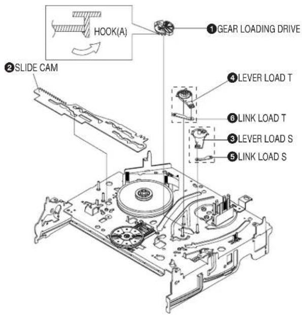
Fig. 2-21 Gear Loading Drive, Slider Cam, Lever T, S Load Ass'y Removal
2-4-10 Gear Loading Drive, Slider Cam, Lever Load S, T Ass'y Assembly
1) When reinstalling, be sure to align dot of Lever Load T Ass'y ① with dot of Lever Load S Ass'y ② as shown in drawing, (Refer to Timing Point 1).
2) Insert the Pin A,B,C,D into the Slider Cam ③ hole,
3) Be sure to align dot of Lever Load T ① and dot of Gear Loading Drive ④, (Refer to Timing Point 2).
4) Aline dot of Gear Loading drive ④ with mark of Slider Cam ③ as shown in drawing (Refer to Timing Point 3).
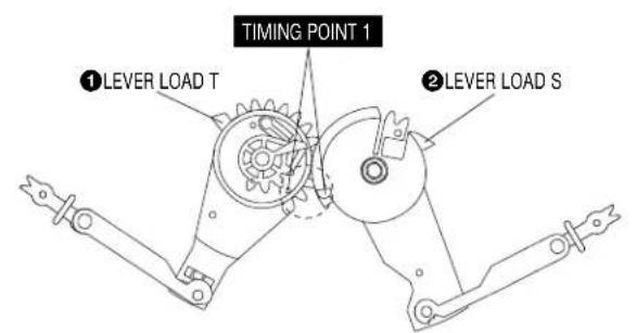
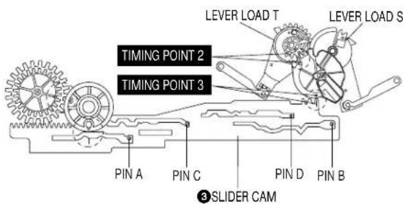
Fig. 2-22 Gear Loading Drive, Slider Cam, Lever Load S, T Ass'y Assembly
2-4-11 Lever Pinch Drive, Lever Tension Drive Removal
1) Remove the Lever Pinch Drive ①, Lever Tension Drive ②.
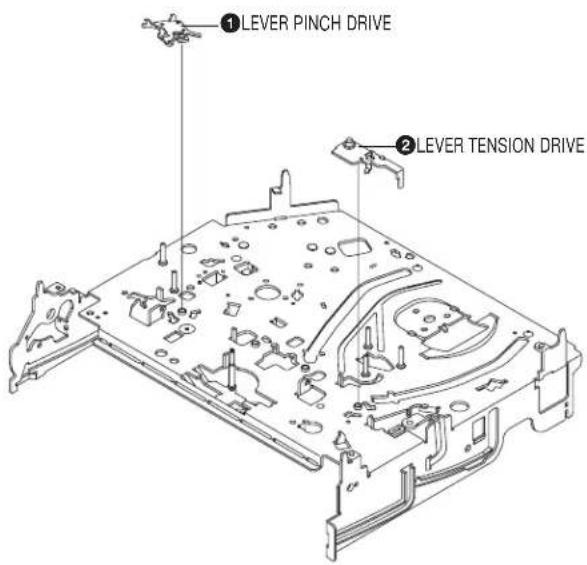
Fig. 2-23 Lever Pinch Drive, Lever Tension Drive Removal
2-4-12 Lever Tension Ass'y, Band Brake Ass'y Removal
1) Remove the Lever Brake S Ass'y (Refer to Fig 2-25).
2) Remove the Spring Tension Lever 1
3) Rotate stopper of Main Base in the direction of arrow "A".
4) Lift the Lever Tension Ass'y ② & Band brake Ass'y ③.
Note:
1) When replacing the Lever Tension Ass'y ②, be sure to apply Grease on the post,
2) Take care not to touch stain on the felt side, and not to be folder and broken Band brake Ass'y
3) After Lever Tension Ass'y seated, Rotate stopper of Main Base to the Mark[B].
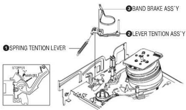
Fig. 2-24 Lever Tension Ass'y, Band Brake Ass'y Removal
2-4-13 Lever Brake S, T Ass'y Removal
1) Release the Hook [A] and the Hook [B], [C] in the direction of arrow as shown in Fig 2-25.
2) Lift the Lever S, T Brake Ass'y ①, ② with spring brake ③.
Assembly:
1) Assembly the Lever S Brake Ass'y ① on the Main Base.
2) Assembly the Lever T Brake Ass'y ② with spring brake ③.
Note: Take extreme care not to be folded and transformed Spring Brake at removing or reinstalling.
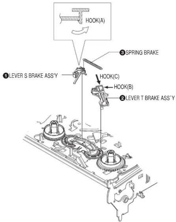
Fig. 2-25 Lever Brake S, T Ass'y Removal
2-4-14 Gear Idle Ass'y Removal
1) Push the Lever Idle ① in the direction of arrow "A", "B". 2) Lift the Lever Idle ①.
Assembly:
1) Apply oil in two Bosses of Lever Idle ①.
2) Assemble the Gear Idle ② with the Lever Idle ①.
Note: When replacing the Gear Idle ②, be sure to add oil in the boss of Lever Idle ①.
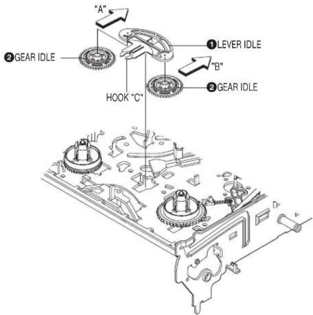
Fig. 2-26 Gear Idle Ass'y Removal
2-4-15 Disk S, T Reel Removal
1) Lift the Disk S, T Reel ①, ②.
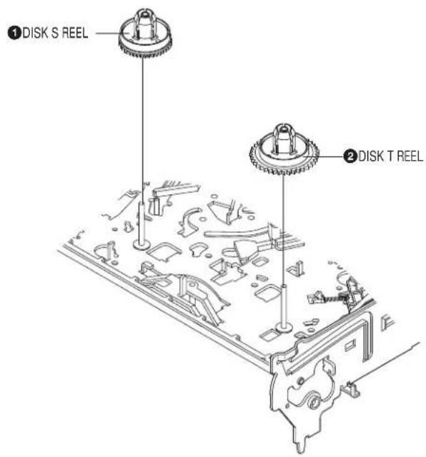
Fig. 2-27 Disk S, T Reel Removal
2-4-16 Holder Clutch Ass'y Removal
1) Remove the Washer Slit ①.
2) Lift the Holder Clutch Ass'y ②.
Note: When you reinstall Holder Clutch Ass'y
1) Check the condition of spring as shown in detail A.
2) Don't push Holder Clutch Ass'y down with excessive force Just insert Holder Clutch Ass'y into post center with dead force and Rotate it smoothly.
Be sure to confirm that spring is in the slit of Gear Center Ass'y as shown in detail B.
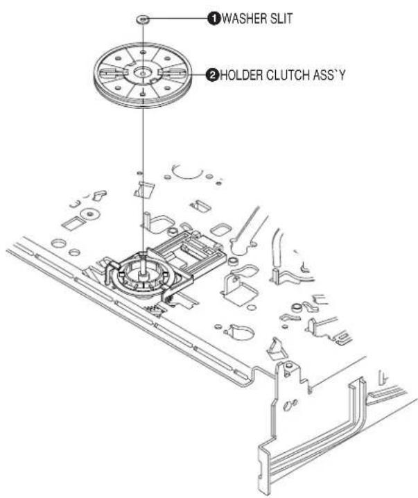
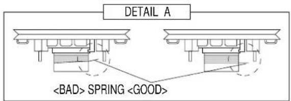
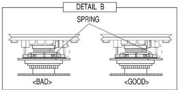
Fig. 2-28 Holder Clutch Ass'y Removal
2-4-17 Lever Up Down Ass'y, Gear Center Ass'y Removal
1) Remove the 2 hooks in the direction of arrow as shown Fig. 2-29 and lift the Lever Up Down Ass'y ①.
2) Lift the Gear Center Ass'y ②.
Assembly:
1) Insert the Lever Up Down Ass'y ① in the rectangular holes on Main Base as shown in Fig 2-30.
2) Lift the Lever Up Down Ass'y ① about 35°. (Refer to Fig 2-30)
3) Insert Ring of the Gear Center Ass'y ② in the Guide of the Lever Up Down Ass'y ①.
4) Insert the Gear Center Ass'y ② in the post on Main Base.
5) Push down the Lever Up Down Ass'y ① for locking of the Hook.
Note:
1) Take care not to separate and sentence does not mark sense.
2) Be sure to confirm that Ring of the Gear Center Ass'y ② is in the Guide of the Lever Up Down Ass'y ① after finishing assembly of Lever Up Down Ass'y ① and Gear Center Ass'y ②.
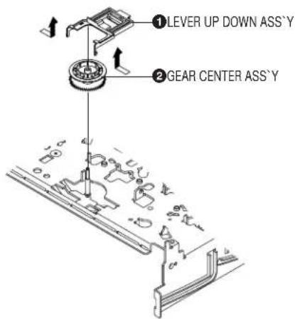
Fig. 2-29 Lever Up Down Ass'y Removal
2-4-18 Guide Cassette Door Removal
1) Lift the Hook [A].
2) Rotate the Guide Cassette Door ① in the direction of arrow.
Note: After reinstalling the Guide Cassette Door ① sure the Hook [A].
![① GUIDE CASSETTE DOOR HOOK [A]](/content/2026/05/1017698/images/fdf013a4d828eca948278e9e50e4940c8f9d84a5e9b08fd2cceee8295c5ea818.jpg)
Fig. 2-31 Guide Cassette Door Removal
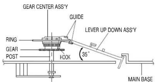
Fig. 2-30 Lever Up Down Ass'y Removal
2-4-19 Lever Unit Pinch Ass'y, Plate Joint, Spring Pinch Drive Removal
I) Lift the Unit Pinch Ass'y ①.
2) Remove the Plate Joint ② from Lever Pinch Drive.
3) Remove the Spring Pinch Drive ③.
Note:
1) Take extreme care not to touch the grease on the Roller Pinch.
2) When reinstalling, be sure to apply grease on the post pinch roller.
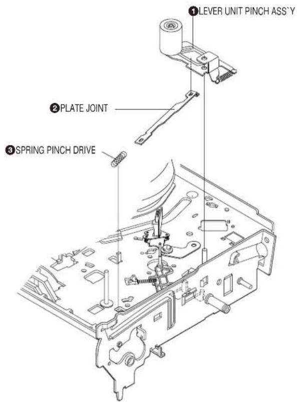
Fig. 2-32 Lever Unit Pinch Ass'y, Plate Joint, Spring Pinch Drive Removal
2-4-20 Lever #9 Guide Ass'y Removal
1) Remove the Spring #9 Guide ①.
2) Lift the Spring #9 Guide Ass'y ② in the direction of arrow "A".
Note:
1) Take extreme care not to get grease on the tape Guide Post.
2) After reinstalling, check the bottom side of the Post #9 Guide to the top side of Main Base.
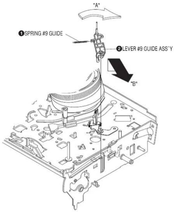
Fig. 2-33 Lever #9 Guide Ass'y Removal
2-4-21 FE Head Removal
1) Remove the screw ①.
2) Lift the FE Head ②.
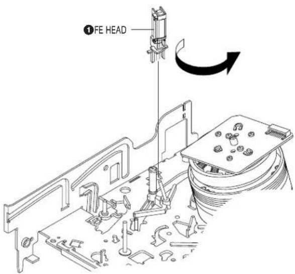
Fig. 2-34 FE Head Removal
2-4-22 ACE Head Removal
1) Pull out the FPC from connector of ACE Head Ass'y ②.
2) Remove the screw 1.
3) Lift the ACE Head Ass'y ②.
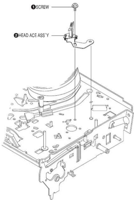
Fig. 2-35 ACE Head Removal
2-4-23 Slider S, T Ass'y Removal
1) Move the Slider S, T Ass'y ①, ② to slot, and then lift it to remove. (Refer to arrow)
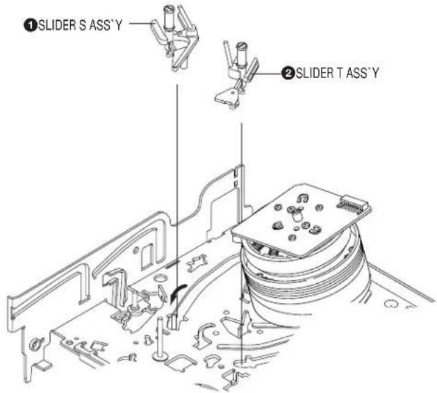
Fig. 2-36 Slider S, T Ass'y Removal
2-4-24 Plate Ground Deck, Cylinder Ass'y Removal
1) Remove the 3 Screws ①.
2) Lift the Plate Ground Deck ②.
3) Lift the Cylinder Ass'y ③.
Assembly:
1) Match the 3 holes in the bottom of Cylinder Ass'y ③ to the 3 holes of Main Base as attending not to drop or knock the Cylinder Ass'y ③.
2) Tighten the 1 Screw ①.
3) Match the Plate Ground Deck ② to the Hole of Base Main.
4) Tighten the other 2 Screws ①.
Note:
1) Take care not to touch the Cylinder Ass'y ③ and the tape guide post at reinstalling.
2) When reinstalling, Don't push down too much on Screw Driver.
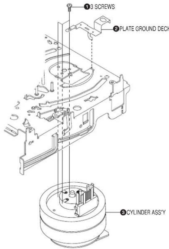
Fig. 2-37 Plate Ground Deck, Cylinder Ass'y Removal
2-4-25 Belt Pulley Removal
1) Remove the Belt Pulley ①.
Note: Take extreme care not to get grease on Belt Pulley 1 at assembling or reassembling.
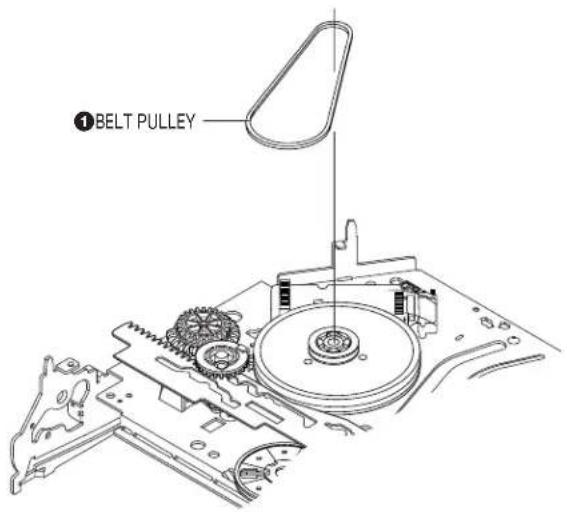
Fig. 2-38 Belt Pulley Removal
2-4-26 Motor Capstan Ass'y Removal
1) Remove the Damper Capstan ① in the direction of arrow.
2) Remove the 3 Screws ②
3) Remove the Motor Capstan Ass'y ③.
Assembly:
1) Match the 3 holes of Motor Capstan Ass'y ③ to the 3 holes of Main Base. Be careful not to drop or knock the Motor Capstan Ass'y ③.
2) Tighten the 3 Screws ② in the direction of arrow as shown detail drawing.
3) Assemble the Damper Capstan ①.
Note: After tightening screws, check if there is gap between the head of screws and the top side of Main Base. There should have no gap between the head of screws and the top side of Main Base.
After reinstalling, adjusting the tape transport system again.
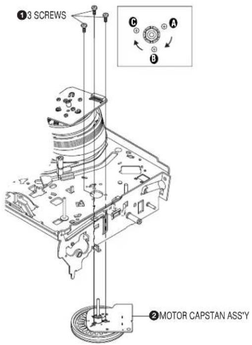
Fig. 2-39 Motor Capstan Ass'y Removal
2-4-27 Post #8 Guide Ass'y Removal
1) Rotate the Post #8 Guide Ass'y ① in the direction of arrow to lift up.
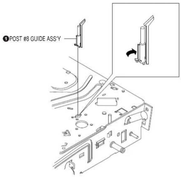
Fig. 2-40 Post #8 Guide Ass'y Removal
2-4-28 Level Head Cleaner Ass'y Removal (Optional)
1) Release the Hook ①.
2) Lift the Lever Head Cleaner Ass'y ②.
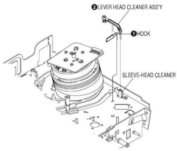
Fig. 2-41 Lever Head Cleaner Ass'y Removal
2-4-29 How to Eject the Cassette Tape (If the unit does not operate on condition that is inserted into housing Ass'y)
1) Turn the Gear worm ① clockwise with screw driver.(Refer to arrow) (Other method: Remove the Screw of Motor Load Ass'y, Separate the Motor Load Ass'y)
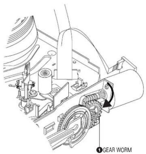
Fig. 2-42
2) When Slider S,T are approached in the position of unloading, rotate holder Clutch counterclockwise after inserting screw driver in the hole of frame's bottom in order to wind the unwinded tape. (Refer to Fig.2-43)
(If you rotate Gear Worm ① continuously when tape is in state of unwinding, you may cause a tape contamination by grease and tape damage. Be sure to wind the unwinded tape in the state of set horizontally.)
3) Rotate Gear Worm ① clockwise using screw driver again up to the state of eject mode and then pick out the tape.(Refer to Fig.2-42)
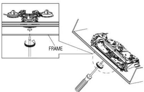
Fig. 2-43
2-5 THE TABLE OF CLEANING, LUBRICATION AND REPLACEMENT TIME ABOUT PRINCIPAL PARTS
1) The replacement time of parts is not life of parts.
2) The table 2-1 is that the VCR Set is in normal condition (normal temperature, normal humidity).
The checking period may be changed owing to the condition of use, runtime and environmental conditions.
3) Life of the Cylinder Ass'y is depend on the condition of use.
4) See exploded view for location of each parts.
| * Parts Name | Checking Period | Remark | ||||||||||
| 500 1000 1500 | 2000 25 | 00 3000 | 3500 40 | 00 4500 | 5000 | |||||||
| TAPEPATH SYSTEM | POST TENSION Δ | Δ | Δ | Δ | Δ | Δ | Δ | Δ | Δ | Δ | - To clean the parts, use patch and alcohol (solvent).- After cleaning, use the video tape after alcohol is gone away completely. - We recommend to use oil [EP-50] or solvent. - One or two drops of oil should be applied after cleaning with alcohol. | |
| SLANT POST S, T Δ | Δ | Δ | Δ | Δ | Δ | Δ | Δ | Δ | Δ | |||
| #8 GUIDE SHAFT Δ | Δ | Δ | Δ | Δ | Δ | Δ | Δ | Δ | Δ | |||
| CAPSTAN SHAFT Δ | Δ | Δ | Δ | Δ | Δ | Δ | Δ | Δ | Δ | |||
| #9 GUIDE POST Δ | Δ | Δ | Δ | Δ | Δ | Δ | Δ | Δ | Δ | |||
| #3 GUIDE POST Δ | Δ | Δ | Δ | Δ | Δ | Δ | Δ | Δ | Δ | |||
| GUIDE ROLLER S, T Δ | Δ | Δ | O | O | O | O | O | O | O | |||
| CYLINDER ASS'Y Δ O | O | O | O | O | O | O | O | O | ||||
| FE HEAD | Δ | Δ | Δ | O | O | O | O | O | O | O | ||
| ACE HEAD | Δ O | O | O | O | O | O | O | O | O | |||
| PINCH ROLLER Δ O | O | O | O | O | O | O | O | O | ||||
| POST REEL S, T | ◆ | ◆ | ◆ | ◆ | ◆ | - Periodic time of applying oil (Apply oil after cleaning) - The excessive applying oil may be the cause of malfunction. | ||||||
| SLEEVE TENSION | ◆ | ◆ | ◆ | ◆ | ◆ | |||||||
| POST CENTER | ◆ | ◆ | ◆ | ◆ | ◆ | |||||||
| LEVER IDLE BOSS (2Point) | ◆ | ◆ | ◆ | ◆ | ◆ | |||||||
| DRIVING SYSTEM | CAPSTAN MOTOR PULLEY | Δ | Δ | Δ | Δ | Δ | O | O | O | O | O | |
| BELT PULLEY | O | O | O | O | O | O | O | |||||
| HOLDER CLUTCH ASS'Y | Δ O | O | O | O | O | O | O | O | O | |||
| GEAR CENTER ASS'Y | O | O | O | O | O | O | O | O | O | |||
| GEAR IDLE (2Point) | O | O | O | O | O | O | O | O | O | |||
| LOADING MOTOR | O | O | O | O | O | O | O | O | O | |||
| BRAKE SYSTEM | BAND BRAKE ASS'Y | O | O | O | O | O | O | O | O | O | ||
| BRAKE T ASS'Y | O | O | O | O | O | O | O | O | O | |||
2-6-2 Ass'y P/U Deck Removal
1) Disconnect DCN2 ①, DCN3 ②. 2) Lift down the Assy P/U Deck ③ while simultaneously pushing 2 Hooks ④, ⑤ in the direction of arrow "A", "B".  Fig. 2-45 Assy P/U Deck Removal2-6-2 Assy P/U Deck Removal
1) Disconnect DCN2 ①, DCN3 ②. 2) Lift down the Assy P/U Deck ③ while simultaneously pushing 2 Hooks ④, ⑤ in the direction of arrow "A", "B".  Fig. 2-45 Assy P/U Deck Removal2-6-3 Housing Ass'y Removal
1) Remove Belt ①. 2) Push the Hook ② in the direction arrow "A" and lift up Pulley Gear ③. 3) Push the Slider Housing ⑤ in the direction arrow "B" and lift up the Gear Tray ④. 4) Lift up the Slider Housing 5. 5) Remove 2 Screws ⑥ and lift down the Motor Load Assy ⑦. 6) Remove Clamper Ass'y 8.  Fig. 2-46 Housing Ass'y Removal2-6-4 Sub Chassis Removal
1) Remove the Soldering of Motor Feed (+, - wire) ①. 2) Remove the 4 Screws ②. 3) Lift up the Ass'y Brkt Deck ③.  Fig. 2-47 Sub Chassis Removal2-6-5 Ass'y Brkt Deck Removal
1) Push the Hook ① in the direction arrow "A" and lift up Gear Feed B ②. 2) Remove 3 Screws ③ and 3 Holder Cam Skew ④. 3) Remove Shaft Pick-Up ⑤ and Pick-Up Assy ⑥ 4) Remove Gear Feed A ⑦. 5) Remove 2 Screws 8. 6) Remove Motor Feed Ass'y ⑨. 7) Remove 3 Screws 10. 8) Remove Motor Spindle ⑪.  Fig. 2-48 Ass'y Brkt Deck Removal3. BLOCK DIAGRAM
flowchart
graph TD
    A["DECK ASS'Y (DP-9)"] --> B["Pick-up & JV Amp"]
    B --> C["Disk Motor"]
    B --> D["Feed Motor"]
    C --> E["SIC3 (FAN8728) Motor Driver"]
    D --> E
    E --> F["RIC1 (SSL1463) RF Amp & OPD"]
    F --> G["SIC1 (SSL1465X) DVD & CD Processor & Digital"]
    G --> H["SIC2 4M E20-RAM"]
    F --> I["ZIC1 (VADDISSE) A/V Decoder"]
    I --> J["ZIC2 64MB 5DRAM"]
    I --> K["ZIC3 (MBM28LV800BA) IMB Flash Memory"]
    I --> L["ZIC7 (NCI02) EPROM"]
    L --> M["ZIC6 (TC74VHCT125) Level Shiftar"]
    M --> N["IC601 (uPD7B4928GF) VCR Main Micom"]
    N --> O["IC701 (PT6961) LED Drive"]
    O --> P["(DT701)"]
    Q["A/V Common"] --> R["SCART JACK"]
    R --> S["VIDEO"]
    R --> T["AUDIO L"]
    R --> U["AUDIO R"]
    R --> V["Audio L/R"]
    W["Super"] --> X["IC802, IC803 (BU4053) Output Signal Switch"]
    X --> Y["IC501 (LA72645) Hi-Fi Audio Processor"]
    Y --> Z["IC301 (LA71750EM) Video Signal Processor"]
    Z --> AA["IC605 EEPROM"]
    AA --> AB["Front A/V Jack"]
    AC["Optical Control"] --> AD["Microcontroller"]
4. PCB DIAGRAMS
4-1 VCR Main 4-3 4-2 DVD Main 4-7 4-3 S.M.P.S. 4-11 4-4 Function 4-13 4-5 Dial-Timer (SLV-D950B/D950E/D950GI/D910AZ Only) 4-134-1 VCR MAIN
COMPONENT SIDE
 CONDUCTOR SIDE natural_image
Black-and-white technical schematic of a printed circuit board (PCB) with no visible text, numbers, or symbols.4-2 DVD MAIN
COMPONENT SIDE
 CONDUCTOR SIDE  4-3 S.M.P.S. COMPONENT SIDE CONDUCTOR SIDE  4-4 FUNCTION
COMPONENT SIDE  CONDUCTOR SIDE 4-5 DIAL-TIMER (SLV-D950B/D950E/D950GI/D910AZ Only)
COMPONENT SIDE  CONDUCTOR SIDE  MEMO5. SCHEMATIC DIAGRAMS
◆ Block Identification of Main PCB 5-3VCR Main PCB
5-1 S.M.P.S. 5-5 5-2 Power Drive 5-7 5-3 OSD/VPS/PDS 5-9 5-4 A2/NICAM 5-11 5-5 Audio/Video 5-13 5-6 Hi-Fi 5-15 5-7 Input-Output- 5-17 5-8 TM 5-19 5-9 Syscon 5-21 5-10 Logic/Function 5-23 5-11 SECAM (SLV-D950B/D910B/D910R Only) 5-25DVD Main PCB
5-12 DVD Main-Micom/AV Decoder 5-27 5-13 DVD Servo 5-29 5-14 DVD Audio/Video 5-31Note
For schematic Diagram \- Resistors are in ohms, 1/8W unless otherwise noted. Special note Most semiconductor devices are electrostatically sensitive and therefore require the special handling techniques described under the "electrostatically sensitive (ES) devices" section of this service manual. Important safety notices : Components identified with the mark A to have the special characteristics for safety. When replacing any of these components. Use only the same type. ◆ BLOCK IDENTIFICATION OF MAIN PCB  5-1 S.M.P.S. 5-2 POWER DRIVE
  5-4 A2/NICAM
5-5 AUDIO/VIDEO
 5-6 Hi-Fi 5-7 INPUT-OUTPUT
 5-9 SYSCON
 5-10 LOGIC/FUNCTION 5-11 SECAM (SLV-D950B/D910B/D910R Only)
 5-12 DVD MAIN-MICOM/AV DECODER 5-13 DVD SERVO
5-14 DVD AUDIO/VIDEO
 5-32E5-316. ALIGNMENT AND ADJUSTMENTS
6-1 VCR ADJUSTMENT
6-1-1 Reference
1) X-Point (Tracking center) adjustment, "Head switching adjustment" and "NVRAM option setting" can be adjusted with remote control. 2) When replacing the Main PCB Micom (IC601) and NVRAM (IC605; EEPROM) be sure to adjust the "Head switching adjustment" and "NVRAM option setting". 3) When replacing the cylinder ass'y, be sure to adjust the "X-Point" and "Head switching adjustment". 4) How to adjustment. - Intermittently short-circuit the Test Point on Main PCB with pincers to the adjustment mode. - If the corresponding adjustment button is pressed, the adjustment is performed automatically. - If the adjustment is completed, be sure to turn the power off.6-1-1(a) Location of adjustment button of remote control
6-1-2 Head Switching Point Adjustment
1) Playback the alignment tape. 2) Intermittently short-circuit the two Test Points on VCR Main PCB while setting the adjustment mode. (See Fig. 6-2) 3) Press the "1, 0" buttons; remote control adjustment operates automatically. (See Fig. 6-1)6-1-3 NVRAM Option Setting
1) NVRAM Option is adjusted in the factory. 2) In case Main PCB Micom (IC601) and NVRAM (IC605; EEPROM) are replaced, be sure to set the corresponding option number of the required model. (If the option is not set, the unit will operate.) 1) Intermittently short-circuit the two Test Points on VCR Main PCB. (See Fig. 6-2) 2) Press the "1, 4" buttons on the remote control. The option setting is appears. (See Fig. 6-3) 3) Select the option number (See table 6-1) of corresponding model with “◀, ▶, ♠, ▼” buttons on the remote control. 4) After selecting the option number is completed, press the "ENTER" button of remote control. (If "ENTER" button is pressed, the selected number is changescolor.; See Fig. 6-4) 5) Press the "RETURN" button of remote control again to store the option number. 6) Turn the Power off.  Fig. 6-3 Fig. 6-4 | MODEL OPTION NUMBERS | |
| SLV-D950E 2, 4, 5, 6, | 7, 8, 9, 10, 11, 12, 13, 15, 32, 34, 35, 38, 40, 42, 45, 47, 60, 61, 63, 64, 69, 70, 72 |
| SLV-D910E 4, 5, 6, 7, | 8, 9, 10, 11, 12, 13, 15, 32, 34, 35, 38, 40, 42, 45, 47, 60, 61, 63, 69, 70, 72 |
| SLV-D950B | 2, 4, 5, 6, 7, 8, 9, 10, 11, 12, 13, 15, 20, 21, 26, 32, 33, 34, 35, 36, 38, 40, 45, 47, 60, 61, 63, 64, 69, 70, 72 |
| SLV-D910B 4, 5, 6, 7, | 8, 9, 10, 11, 12, 13, 15, 20, 21, 26, 32, 33, 34, 35, 36, 38, 40, 45, 47, 60, 61, 63, 69, 70, 72 |
| SLV-D950GI 3, 4, 5, 6, | 8, 9, 10, 11, 12, 13, 15, 25, 26, 32, 33, 34, 35, 38, 40, 41, 45, 47, 60, 61, 63, 64, 69, 70 |
| SLV-D910N 4, 5, 6, 7, | 8, 9, 10, 11, 12, 13, 15, 20, 32, 36, 38, 42, 45, 47, 60, 61, 63, 69, 70, 72 |
| SLV-D910R 6, 7, 8, 9, | 10, 11, 12, 13, 15, 20, 32, 36, 37, 39, 42, 45, 47, 60, 61, 63, 69, 70 |
| SLV-D910AZ 6, 7, 8, 9, | 10, 12, 15, 25, 26, 27, 32, 33, 35, 36, 39, 42, 45, 47, 53, 60, 61, 63, 64, 70 |
6-2-2 Skew Adjustment
6-2-2(a) Adjustment Spec. and Test Point| Test Disc Adjustment Spec. Test Point Adjustment Location | |||
| TDV-533 “SKEW” Ass'y Deck - Top SideChapter 14 Flat Waveform (DVD Main PCB - Bottom Side) (See Fig. 6-6)(P/N: J-6090-135-A) (See Fig. 6-5) | |||
6-2-2(b) SKEW Adjustment Method
Needed to minimize the variations in Skew of the Pickup unit and to provide optimum match with the recorded signal on the Disc. 1) Connect an Oscilloscope to the "SKEW" Test Point (See Fig. 6-5). 2) Connect Power, Open the Tray and Play the TDV-533 Disc, Chapter 14. ◆ Set the Oscilloscope Range as follows : (Voltage ; 50mV/Div., Frequency ; 10m Sec.) 3) Adjust the Screws "A" and "B" (See Fig. 6-6) using a Hex screwdriver until you obtain a Flat Waveform and the picture is stable. Then, go to Chapter 1 and make sure the Waveform is Flat here as well. If not, you have to go back to Chapter 14 and adjust again. If you cannot obtain a Flat waveform, then the unit is defective. Note: The Deck must be in a horizontal position. Use both "A" and "B" screws to adjust. natural_image
Oscilloscope waveform display showing a zigzag signal against a grid background (no readable text or symbols)natural_image
Green sine wave signal plotted on a grid background (no text or labels)natural_image
A green line fluctuating slightly above a dashed grid background (no text or symbols)6-3-1 Tape Transport System and Adjustment Locations
The tape transport system has been adjusted precisely in the factory. Alignment is not necessary except for the following : 1) Noise observed on the screen. 2) Tape damage. 3) Parts replacement in the tape transport system. Lower flange height of tape guide is used as the reference for the transport adjustment. To maintain the height of the tape guide and prevent damage, do not apply excessive force onto the main base.  Fig. 6-8 Location of Tape Transport Adjustment  Fig. 6-9 Tape Travel Diagram6-3-2 Tape Transport System Adjustment
When parts are replaced, perform the required adjustments by referring to procedures for the tape transport system. If there are any changes to the tape path, first run a T-120 tape and make sure excessive tape wrinkle does not occur at the tape guides. ◆ If tape wrinkle is observed at the guide roller S, T, turn the guide roller S, T until wrinkle disappears. ◆ If the tape wrinkle is still observed at the tape guide, perform the tilt adjustment of the ACE head.(1) ACE Head Assembly Adjustment
a. ACE HEAD HEIGHT ADJUSTMENT
1) Run the alignment tape (Color bar) in the playback mode. 2) Observe surface of the audio head using a dental mirror. 3) Turn screw (C) clockwise or counterclockwise until the gap of lower tape edge and the lower edge of the control head is about 0.25mm. (Refer to Fig. 6-10 and 6-11)  Fig. 6-10 Location of ACE Head Adjustment Screw  Fig. 6-11 ACE Head Height Adjustmentb. ACE HEAD TILT ADJUSTMENT
1) Playback a blank tape and observe the position of the tape at the lower flange of tape guide. 2) Confirm that there is no curl or wrinkle at the lower flange of tape guide as shown in Fig. 6-12 (B). 3) If a curl or wrinkle of the tape occurs, slightly turn the screw (A) tilt adjust on the ACE head ass'y. 4) Reconfirm the ACE head height.  Fig. 6-12 Tape Guide Checkc. AUDIO AZIMUTH ADJUSTMENT
1) Load alignment tape (Mono scope) and playback the 6KHz signal. 2) Connect channel-1 scope probe to audio output. 3) Adjust screw (B) to achieve maximum audio level. (See Fig. 6-10)d. ACE HEAD POSITION (X-POINT) ADJUSTMENT
1) Playback the alignment tape (Color bar) 2) Intermittently short-circuit the two Test Points on VCR Main PCB. (See Fig. 6-2) 3) Press the "0, 5" remote control buttons, then adjustment is operates automatically. (See Fig. 6-1) 4) Connect the CH-1 probe to "Envelope" the CH-2 probe to "H'D switching pulse" and then trigger to CH-1. 5) Insert the (-) driver into the X-Point adjustment hole and adjust it so that envelope waveform is maximum. Test point: W568 (Audio Output) W569 (Envelope) W570 (H'D S/W -Trigger) W571 (Control Pulse) flowchart
graph TD
    A["CONTROL PULSE"] --> B["HEAD SWITCHING"]
    B --> C["ENVELOPE"]
    C --> D["AUDIO OUTPUT"]
    E["10"] --> F["12"]
    G["13"] --> H["14"]
    I["15"] --> J["16"]
    K["17"] --> L["18"]
    M["19"] --> N["20"]
    O["21"] --> P["22"]
    Q["23"] --> R["24"]
(2) Linearity adjustment (Guide roller S, T adjustment)
1) Playback the Mono Scope alignment tape (SP mode). 2) Observe the video envelope signal on an oscilloscope (triggered by the video switching pulse). 3) Make sure the video envelope waveform (at its minimum) meets the specification shown in Fig. 6-14. If it does not, adjust as follows:Note:
a=Maximum output of the video RF envelope. b=Minimum output of the video RF envelope at the entrance side. c=Minimum output of the video RF envelope at the center point. d=Maximum output of the video RF envelope at the exit side. 4) If the section A in Fig. 6-15 does not meet the specification, adjust the guide roller S up or down. 5) If the section B in Fig. 6-15 does not meet the specification, adjust the guide roller T up or down.  Fig. 6-14 Envelope Waveform Adjustment  Fig. 6-15 Adjustment Points 6) Play back the Mono Scope alignment tape (SP mode). 7) Connect an oscilloscope CH-1 to the "Envelope" and CH-2 to the "H'D SW Pulse" for triggering. 8) Turn the guide roller heads with a flat head (☐) driver to obtain a flat video RF envelope as shown in Fig. 6-16. flowchart
graph TD
    A["IDEAL ENVELOPE"] --> B["S HEIGHT TOO HIGH"]
    A --> C["S HEIGHT TOO LOW"]
    A --> D["T HEIGHT TOO HIGH"]
    A --> E["T HEIGHT TOO LOW"]
    B --> F["GUIDE ROLLER S"]
    C --> F
    D --> F
    E --> F
    F --> G["GUIDE ROLLER T"]
(3) Check Transitional Operation from RPS to Play
Check transition from RPS mode to play mode: Using a pre-recorded SP tape, make sure the entry side of envelope comes to an appropriate steady state within 3 seconds (as shown in Fig. 6-17). If the envelope waveform does not reach specified peak-to peak amplitude within 3 seconds, adjust as follows : 1) Make sure there is no gap between the supply roller lower flange and the tape. If there is a gap, adjust the supply guide roller again. 2) Change operation mode from the RPS to the play mode (again) and make sure the entry side of envelope rises within 3 second.  Fig. 6-17 Video Envelope Rising when Operation mode Changes from RPS to Play Mode(4) Envelope Check
1) Make recordings on T-120 (E-120) and T-160 (E-180) tape. Make sure the playback output envelope meets the specification as shown in Fig. 6-18. 2) Play back a self recorded tape (recording made on the unit using with T-120 (E-120). The video envelope should meet the specification as shown in Fig. 6-18. In SP mode, (A) should equal (B). If the head gap is wide, upper cylinder should be checked.  Fig. 6-18 Envelope Input and Output Level(5) Tape Wrinkle Check
1) Run the T-160 (E-180) tape in the playback, FPS, RPS and Pause modes and observe tape wrinkle at each guide. 2) If excessive tape wrinkle is observed, perform the following adjustments in Playback mode: ♦ Tape wrinkle at the guide roller S, T section : Linearity adjustment. ♦ Tape wrinkle at tape guide flange : ACE head assembly coarse adjustment.6-3-3 Reel Torque
1) The rotation of the capstan motor causes the holder clutch ass'y to rotate through the belt pulley. 2) The spring wrap PLAY/REV of holder clutch ass'y drives the disk reel S, T through gear idler by rotation of gear center ass'y. 3) Brake is operated by slider cam at FF/REW mode. 4) Transportation of accurate driving force is done by gears. (Gear Center Ass'y) Note: If the spec. does not meet the followings specifications, replace the holder clutch ass'y and then recheck.| MODE TORQUE g/cm GAUGE | ||
| PB 42 ± | 11 Cassette Torquemeter | |
| RPS 145 | ± 30 Cassette Torquemeter | |
7. TROUBLESHOOTING
flowchart
graph TD
    A["No Power\n(Standby LED OFF)"] --> B{Fuse F1SD01 is OK?}
    B -->|Yes| C{AL5.8V D1SS13.}
    C -->|No| D["Check Trans PT1SD1."]
    C -->|Yes| E{AL5V IC601-14, 92, 69, 70, 41.}
    E -->|No| F["Check D620, D692, L605."]
    E -->|Yes| G{AL5.8V L702.}
    G -->|No| H["Check D601C."]
    G -->|Yes| I{AL5V IC701-9, 25}
    I -->|No| J["Check D601C."]
    I -->|Yes| K{Data IN, OUT, CLK IC701-2, 3, 4.}
    K -->|No| L["Check IC701, DT701."]

    M["Play Mode Inoperative\n(VCR Section)"] --> N{EE-VIDEO}
    N -->|No| O["See (Video Missing in EE Mode)"]
    N -->|Yes| P{Insert the cassette tape recorded by another VCR and press PLAY Button}
    P -->|Yes| Q{Play Indicator in the display}
    Q -->|No| R{Press PLAY key in remote control}
    R -->|No| S["Check IC601-58"]
    R -->|Yes| T["Check Timer"]
    Q -->|Yes| U{Mechanism operation}
    U -->|No| V["See (Mechanism doesn't operate in play mode)"]
    U -->|Yes| W{PB-VIDEO}
    W -->|No| X["See (Video missing in play mode)"]
    W -->|Yes| Y["See (PB VIDEO) audio missing in play mode"]
flowchart
graph TD
    A["RECORD MODE DOESN'T OPERATE"] --> B{PLAY OPERATION}
    B -->|NO| C["SEE (PLAY MODE DOESN'T OPERATE)"]
    B -->|YES| D["LOAD VCR WITH A BLANK TAPE AND PRESS RECORD BUTTON"]
    D --> E{REC MODE}
    E -->|EJECT NO| F{SAFETY TAB}
    F -->|YES| G["CHANGE SW602 (REC SW)"]
    F -->|YES| H{REC-VIDEO}
    H -->|NO| I["SEE (VIDEO MISSING IN RECORD MODE)"]
    H -->|YES| J["SEE (AUDIO MISSING IN RECORD MODE)"]
    K["FAST FORWARD DOESN'T OPERATE"] --> L["LOAD TAPE AND PRESS F.FWD BUTTON"]
    L --> M{F.FWD INDICATOR IN THE DISPLAY}
    M -->|NO NO| N{PRESS FF KEY IN REMOTE CONTROL}
    N -->|YES| O["CHECK TIMER"]
    N -->|YES| P["CHECK IC601-58"]
    N -->|YES| Q["MECHANISM STATE IC601-76, 77, 78"]
    Q --> R{F.FWD}
    R -->|STOP| S["SEE (MECHANISM DOES NOT OPERATE IN PLAY MODE)"]
    R -->|STOP| T["SEE (CAPSTAN DOES NOT ROTATE)"]
    R -->|STOP| U["CHECK MECHANISM"]
    R --> V{CAPSTAN MOTOR ROTATION}
    V -->|STOP| W["SEE (CAPSTAN DOES NOT ROTATE)"]
    V -->|STOP| X["CHECK MECHANISM"]
flowchart
graph TD
    A["REWIND DOESN'T OPERATE"] --> B["LOAD A TAPE"]
    B --> C{F.FWD OPERATION}
    C -->|NO| D["SEE (FAST FORWARD DOESN'T WORK)"]
    C -->|YES| E["PRESS REWIND BUTTON"]
    E --> F{REW INDICATOR IN THE DISPLAY}
    F -->|NO| G{PRESS REW KEY IN REMOTE CONTROL}
    G -->|NO| H["CHECK IC601-58"]
    G -->|YES| I["CHECK TIMER"]
    I --> J{MECHANISM STATE IC601-76, 77, 78}
    J -->|STOP| K["SEE (MECHANISM DOES NOT OPERATE IN PLAY MODE)"]
    J -->|REW| L{DOES CAPSTAN MOTOR ROTATE?}
    L -->|NO| M["CHECK IC601-25 (CM F/R)"]
    L -->|YES| N["CHECK MECHANISM"]

    O["FWD SEARCH DOESN'T OPERATE"] --> P{PLAY OPERATION}
    P -->|NO| Q["SEE (PLAY DOESN'T OPERATE)"]
    P -->|YES| R["PRESS F.FWD FOR FORWARD SEARCH"]
    R --> S{IS CAPSTAN SPEED CHANGED?}
    S -->|NO| T["CHANGE DECK"]
    S -->|YES| U{NOISE BAR LOCKING}
    U -->|NO| V["(CONTROL PULSE) IC601-89"]
    V --> W{SEARCH OPERATION}
    W -->|NO| X["CHANGE IC601"]
    W -->|YES| Y["END"]
    W -->|YES| Z["ADJUST A/CE HEAD"]
    W -->|YES| AA["CHECK CAPSTAN MOTOR"]
flowchart
graph TD
    A["REV. SEARCH DOESN'T OPERATE"] --> B{PLAY OPERATION}
    B -->|SEE (PLAY DOESN'T OPERATE)| C["PRESS REWIND BUTTON FOR REV. SEARCH"]
    C --> D{IS CAPSTAN SPEED CHANGED?}
    D -->|NO| E["CHANGE DECK"]
    D -->|YES| F{(SEARCH MODE) YES}
    E --> G{SEARCH OPERATION}
    G -->|NO| H["CHANGE IC601"]
    G -->|YES| I["END"]
    H --> J["FWD SEARCH"]
    J -->|YES| K{CAP F/R IC601-25}
    K -->|HIGH| L["CHECK IC601"]
    K -->|LOW| M["CHECK CAP F/R LINE"]
    L --> N{NOISE BAR LOCKING}
    N -->|NO| O{CONTROL PULSE IC601-89}
    O -->|NO| P["ADJUST A/CE HEAD"]
    O -->|YES| Q["CHECK CAPSTAN MOTOR"]
    N --> R["CHECK IC601 H'D AMP/ENV COMP."]
    S["CASSETTE LOADING MECHANISM DOES NOT OPERATE"] --> T["TURN THE VCR POWER ON AND INSERT A TAPE"]
    T --> U{TAPE DETECTED}
    U -->|NO NO| V{CST IN MODE IC601-74:HIGH(5V) IC601-75:LCW(0V)}
    V -->|YES| W{CN604-8 (12.5V)}
    W -->|NO| X["CHECK DM B+LINE"]
    W -->|YES| Y{IC601-38 (5V) IC601-39 (0V)}
    Y -->|NO| Z["CHECK CASSETT LOADING MECHANISM"]
    Y -->|YES| AA{IC601-39 (5V) IC601-38 (0V)}
    AA -->|YES| AB["CHANGE CAPSTAN MOTOR"]
    AA -->|NO| AC["CHANGE IC601"]
flowchart
graph TD
    A["VIDEO MISSING IN RECORD MODE"] --> B{VIDEO EE MODE OPERATION}
    B -->|NO| C["SEE (VIDEO MISSING IN EE MODE)"]
    B -->|YES| D["PLACE THE VCR RECORD MODE"]
    D --> E{VIDEO SIGNAL IC301-48, 50, 52}
    E -->|NO| F["VIDEO SIGNAL CHECK IC301-48, 50, 54 LINE"]
    E -->|YES| G{VIDEO SIGNAL IC301-59}
    G -->|NO| H["CHECK C340"]
    G -->|YES| I{FM VIDEO IC301-78}
    I -->|NO| J["CHANGE Q307, C3Q4"]
    I -->|YES| K{FM VIDEO IC301-88 (LP) IC301-94 (SP)}
    K -->|NO| L["CHECK CN301 CONNECTION"]
    K -->|YES| M["CHECK VIDEO HEAD"]
flowchart
graph TD
    A["VIDEO MISSING IN EE MODE"] --> B["PLACE VCR IN STOP MODE"]
    B --> C{TUNER MODE OPERATION}
    C -->|NO| D["APPLY VIDEO SIGNAL TO FRONT VIDEO INPUT JACK AND SET TO LINE MODE BY INPUT SEL BUTTON."]
    C -->|YES| E{VIDEO SIGNAL IC301-48}
    E -->|NO| F{VIDEO SIGNAL TM401-24}
    F -->|NO| G["CHECK TM401 ANTENNA IN"]
    F -->|YES| H["CHECK IC301-48 TO TM401-24 LINE"]
    E -->|YES| I{VIDEO SIGNAL IC301-50}
    I -->|NO| J["CHECK JC801 VIDEO SIGNAL"]
    I -->|YES| K{VIDEO SIGNAL IC301-61}
    K -->|NO| L{IIC CLK, DATA IC301-68, 69}
    L -->|NO| M["CHECK IIC CLK, DATA LINE"]
    L -->|YES| N["CHECK IC301"]
    K -->|YES| O{VIDEO SIGNAL JC801}
    O -->|NO| P["CHECK IC301-61 TO JC801-19 LINE"]
    O -->|YES| Q["CHECK TO TV CONNECTION."]
flowchart
graph TD
    A["COLOR MISSING IN RECORD MODE"] --> B{(VIDEO IN) RECORD MODE}
    B -->|NO| C["SEE PAGE 7-6 (VIDEO MISSING IN RECORD MODE)}<br>    B -->|YES| D{COLOR SIGNAL IC301-58}<br>    D -->|YES| E{CHECK XT301}<br>    D -->|NO| F[CHANGE IC301"]
    E -->|NO| G["CHANGE XT301"]
    E -->|YES| H["CHANGE IC301"]
    F --> I{COLOR-KILLER IC301-33(2V)}
    I -->|YES| J["CHECK THE REC LINE"]
    I -->|NO| K["CHANGE IC301"]
flowchart
graph TD
    A["VIDEO MISSING IN PLAY MODE"] --> B{VIDEO EE MODE OPERATION}
    B -->|NO| C["SEE PAGE 7-6 (VIDEO MISSING IN EE MODE)"]
    B -->|YES| D["PLACE THE VCR PLAY MODE"]
    D -->|YES| E{VIDEO FM IC301-21}
    E -->|NO| F{H'D SW IC301-70}
    F -->|NO| G["CHECK IC601-24"]
    F -->|YES| H["CHECK CN501 CONNECTION"]
    E -->|YES| I{VIDEO SIGNAL IC301-78}
    I -->|NO| J["CHECK Q301, C395"]
    I -->|YES| K{VIDEO SIGNAL IC301-65}
    K -->|NO| L["CHANGE IC301 CHECK IC6P01, Q6P01, R6P10"]
    K -->|YES| M{VIDEO SIGNAL IC6P01-19}
    M -->|YES YES YES| N{VIDEO SIGNAL IC301-61}
    N -->|YES YES YES| O["CHECK C380"]
    N -->|YES YES YES| P["CHECK VIDEO OUT LINE"]
flowchart
graph TD
    A["OSD PICTURE MISSING"] --> B{CHECK IC301-65}
    B -->|NO| C["SEE PAGE 7-7 (VIDEO MISSING IN PLAY MODE)"]
    B -->|YES| D{CHECK IC6P01-19}
    D -->|NO| E["CHECK IC6P01-9, 10, 11"]
    D -->|NO| F["CHANGE IC6P01"]
flowchart
graph TD
    A["COLOR MISSING IN PLAY MODE"] --> B{FM-ENV IC301-25}
    B -->|NO| C["SEE PAGE 7-7 (VIDEO MISSING IN PLAY MODE)"]
    B -->|YES| D{COLOR SIGNAL IC301-58}
    D -->|NO| E{COLOR-KILLER IC301-33(2V)}
    D -->|YES| F["CHECK IC301-61"]
    E -->|NO| G["CHECK IC601-29"]
    E -->|YES| H{COLOR-ROTARY IC301-70}
    H -->|NO| G
    H -->|YES| I["CHECK IC301-27, 34 XT301"]
    I --> J["CHANGE IC301"]
    J --> K["End"]
flowchart
graph TD
    A["AUDIO MISSING IN PB MODE"] --> B["CHECK (AUDIO MISSING IN EE MODE)"]
    B --> C["PLACE IN PB MODE"]
    C --> D{AUDIO SELECT}
    D -->|MONO| E{IC301-5 AUDIO SIGNAL}
    E -->|YES| F["CHECK C3A16"]
    E -->|NO| G{IC301-6 DC : 2.3V}
    G -->|YES| H["CHECK ACE HEAD R3A07, R3A08, R3A06, C3A15 AND CHANGE IC301"]
    G -->|NO| I["CHECK C3A17 AND CHANGE IC301"]
    D -->|HI-FI| J{IC501-78, 80}
    J -->|NO| K["CHECK IC501-40, 39, 38 (H'D SW, EC, CLK, IC DATA) AND CHANGE CYLINDER OR IC501"]
    J -->|YES| L["CHANGE IC501"]
flowchart
graph TD
    A["BLUE MISSING IN STOP MODE"] --> B["PACE VCR IN STOP MODE"]
    B --> C{SELECT LINE MODE WITHOUT INPUT SIGNAL}
    C -->|YES| D{IC6P01-8 "H" (SYNC JUDGE)}
    C -->|NO| E{VIDEO SIGNAL IC6P01-19}
    E -->|YES| F["CHECK OSD VIDEO IN LINE"]
    E -->|NO| G["CHECK IC6P01"]
    D -->|YES| H{IC601-72 "H"}
    D -->|NO| I["CHECK IC6P01-8 TO IC601-72"]
    H -->|YES| J{IC6P01-9, 10, 11 (STB, CLK, DATA)}
    H -->|NO| K["CHECK IC601-6, 7, 8"]
    J -->|YES| L["CHANGE IC601"]
    J -->|NO| M["CHECK IC601"]
flowchart
graph TD
    A["MONO"] --> B["CHECK (AUDIO MISSING IN PB MODE)"]
    B -->|YES| C{IC301-15 AUDIO SIGNAL}
    B -->|NO| D["CHECK PB MODE"]
    C -->|YES| E{IC301-11 AUDIO SIGNAL}
    C -->|NO| F{IC501-4 AUDIO SIGNAL}
    F -->|YES| G["CHANGE IC501"]
    F -->|NO| H["CHECK C523, R512, R511"]
    E -->|YES| I{IC301-100 AUDIO SIGNAL}
    E -->|NO| J["CHECK IC301-14, C3A02, IC301-12 AND CHANGE IC301"]
    I -->|YES| K{IC301-5 MIX SIGNAL (AUDIO+70KHz)}
    I -->|NO| L["CHECK R3A04"]
    K -->|YES| M{CN3A01-4 OSCILLATION}
    K -->|NO| N["CHECK Q3A03, Q3A02"]
    L -->|YES| O["CHECK ACE HEAD"]
    L -->|NO| P["CHECK IC301-68, 69 CLOCK, DATA"]
flowchart
graph TD
    A["AUDIO MISSING IN REC MODE"] --> B["CHECK (AUDIO MISSING IN EE MODE)"]
    B --> C{MISSING AUDIO}
    C -->|MONO| D["MONO"]
    C -->|HIFI| E{IC501-7, 69 AUDIO SIGNAL}
    E -->|NO| F["CHECK R815, R816, L809, L810, JC801"]
    E -->|YES| G{IC501-26 AUDIO FM}
    G -->|NO| H{CHECK IC501 5V AND 9V LINE}
    H -->|NO| I["CHECK IC501-38, 39 (CLK, DATA)"]
    H -->|YES| J["CHANGE IC501"]
    G -->|YES| K["CHECK CYLINDER"]
flowchart
graph TD
    A["CAPSTAN DOES NOT ROTATE"] --> B{CN604-2 24V}
    B -->|NO| C["CHECK B+ IN THE POWER BLOCK"]
    B -->|YES| D{CN604-3 PC 5V}
    D -->|NO| E["CHECK 5.8V AT PC5.8V LINE IN THE POWER BLOCK"]
    D -->|YES| F["PLACE THE VCR IN PLAY MODE"]
    F --> G{CN604-9}
    G -->|NO NO| H{IC601-10 CAP M CTL}
    G -->|YES| I{CN604-5}
    H -->|YES| J["CHANGE IC601"]
    H -->|YES| K["CHECK R609, R685, C623"]
    H -->|NO| L{CN601-3 OUTPUT (PWM)}
    L -->|NO| M["CHECK IC601"]
    L -->|YES| N["CHECK CAPSTAN MOTOR"]
    L -->|YES| O["CHECK R660, C691"]
flowchart
graph TD
    A["AUDIO MISSING IN EE MODE"] --> B["PLACE VCR IN STOP MODE"]
    B --> C{INPUT SELECT MODE}
    C -->|LINE| D{IC501-7, 69 AUDIO SIGNAL INPUT}
    D -->|NO| E["CHECK R517, R518, R509, R510"]
    C -->|TUNER| F{IC501-51, 53 AUDIO SIGNAL INPUT}
    F -->|NO| G["CHECK TUNER BLOCK AND IC4N01"]
    F -->|YES| H{IC501-38, 39 CLK DATA}
    H -->|NO| I["CHECK IC601"]
    H -->|YES| J{IC501-78, 80 AUDIO SIGNAL}
    J -->|NO| K["CHECK IC501"]
    J -->|YES| L["CHECK C524, C525, R546, R547"]
flowchart
graph TD
    A["DRUM DOES NOT ROTATE"] --> B{CN604-8 12V}
    B -->|NO| C["CHECK AL12V IN THE POWER BLOCK"]
    B -->|YES| D["PLACE THE VCR IN PLAY MODE"]
    D --> E{CYL-SPEED}
    E -->|FASTER| F["CHECK D-PG, D-FG IC601-97"]
    E -->|SLOWER| G{IC601-18, 19 (8MHZ)}
    G -->|NO| H["CHANGE XT601, C626, C627"]
    G -->|YES| I["CHECK CYLINDER MOTOR"]
flowchart
graph TD
    A["No pick-up home positing"] --> B{SIC1-26(SLD) output is normal? (1.7V ~ 1.8V)}
    B -->|Yes| C["SLED+, SLED-SIC3-32, 33 output are normal?"]
    B -->|No| D["Check SIC1"]
    C -->|Yes| E["Check the Sled Motor and connection"]
    C -->|No| F["Check SIC3"]
flowchart
graph TD
    A["No focus incoming"] --> B{FE in SIC1-8 is within specified range?}
    B -->|No| C["Check RIC1 and A, B, C, D input."]
    B -->|Yes| D{SIC3-27, 28 output are normal?}
    D -->|No| E["Check SIC3."]
    D -->|Yes| F["Check open state from SIC3 to pick-up."]
    C --> G["(FE Waveform)"]
    E --> G
    F --> G
flowchart
graph TD
    A["No Search Operation"] --> B{MIRR, SIC1-37 output is normal?}
    B -->|No| C{RFAGCO, RIC1-73 output level is normal?}
    C -->|No| D["Check pick-up."]
    C -->|Yes| E["Check RIC1 peripheral circuit."]
    B -->|Yes| F["(MIRR Waveform)"]
    F --> G{Actual velocity occurs at SIC1-152 terminal?}
    G -->|No| H["Check SIC1 peripheral circuit."]
    G -->|Yes| I{Actual velocity occurs at SIC3-32, 33 terminal?}
    I -->|No| J["Check SIC3 peripheral circuit."]
    I -->|Yes| K{occurs in search range?}
    K -->|No| L{Focus On?}
    L -->|No| M["A"]
    L -->|Yes| N["See "Fine Seek Check""]
flowchart
graph TD
    A["NO DVD LD ON"] --> B{RIC1-22 is 5V?}
    B -->|No| C["Check RIC1"]
    B -->|Yes| D["Divide RQ2 emitter terminal voltage and 5V real voltage difference into 10chm."]
    D -->|Yes| E{Current exceeds 0.1A?}
    E -->|No| F["Open check in related circuit."]
    E -->|Yes| G["LD out pick-up replace."]
flowchart
graph TD
    A["Abnormal rotation of disc motor"] --> B{Input of RF EQO signal is normal? (SIC1-152)}
    B -->|No| C{RIC1-71 output is normal?}
    C -->|Yes| D["Check path to RIC1 and SIC1."]
    C -->|No| E["Check RIC1 peripheral circuit and A, B, C, D."]
    B -->|Yes| F{SPD output is normal? (SIC1-28)}
    F -->|No| G["After resoldering SIC1."]
    F -->|Yes| H["(SPD Waveform)"]
    G --> I{SIC3-7(FG) output is normal?}
    I -->|No| J["Check SIC3 soldering and power. (FG Waveform)"]
    I -->|Yes| K{SIC3-44 signal MON is "H" ?}
    K -->|No| L["Check SIC1."]
    K -->|Yes| M["Check or replace disc motor."]
flowchart
graph TD
    A["FINE SEEK Check"] --> B{FINE SEEK MIRR signal (RIC1-67) is missing?}
    B -->|Yes| C["Check RIC1 Peripheral circuit."]
    B -->|No| D{TZCO signal (SIC1-159) is occurs?}
    D -->|No| E["Check SIC1 Peripheral circuit."]
    D -->|Yes| F{Track incoming is delayed?}
    F -->|No| G["Time out due to many jump counts."]
    F -->|Yes| H{TE is within 2V and 3V?}
    H -->|No| I{SIC1-14(TRD) output is normal?}
    I -->|No| J["Check RIC1-36 terminal."]
    I -->|Yes| K{SIC3-30, 29(T+, T-) terminal outputs are normal?}
    K -->|No| L["Check SIC3 peripheral circuit."]
    K -->|Yes| M["Check MECHA."]
    H -->|Yes| N["Pick-up transfer smooth."]
    N -->|No| O["Check SIC1 peripheral circuit."]
    N -->|Yes| P["Check CN1 and pick-up."]
flowchart
graph TD
    A["CD/VCD/DVD L/R output error (Mixed Audio output)"] --> B{Normal DATA 0 is input in AIC2-2?}
    B -->|No| C["Check ZIC1-184 output."]
    B -->|Yes| D{CHECK AIC2-7, 8pin output is normal?}
    D -->|No| E["Check ZIC1-179 (CD/VCD : 16.9344MHz, DVD : 18.432MHz)"]
    D -->|Yes| F{AIC4-1, 7 output is normal?}
    F -->|No| G["Check AIC4 peripheral circuit."]
    F -->|Yes| H["Check PCB peripheral Pattern shot."]
flowchart
graph TD
    A["No Tray open/close"] --> B{ZIC1-24, 25 is Open; "L"? Close; "H"?}
    B -->|No| C["Check ZIC1 peripheral circuit."]
    B -->|Yes| D{Check SIC3-34, 35 output at OPEN/CLOSE}
    D -->|No| E["Check SIC3 peripheral circuit and CN3 connector."]
    D -->|Yes| F["Check signal line state from SIC3-34, 35 to tray motor."]
    F --> G["(OPEN Waveform)"]
flowchart
graph TD
    A["Y/Pr/Pb output error"] --> B{Did the screen select with the component}
    B -->|No| C["Change a scan set"]
    B -->|Yes| D{VIC1-21, 23, 25pin output is normal?}
    D -->|No| E["Check the circuit ZIC1 and VIC1"]
    D -->|Yes| F{JACK1 output level is normal?}
    F -->|No| G["Check the connection between VIC1 and JACK1"]
    F -->|Yes| H["Check the connection component cable"]
flowchart
graph TD
    A["S-Video output error"] --> B{Did the screen select with the s-video}
    B -->|No| C["Change a screen set"]
    B -->|Yes| D{VIC1-28, 31 output is normal?}
    D -->|No| E["Check the circuit of ZIC1, VIC1"]
    D -->|Yes| F{S-JACK output is normal?}
    E --> F
    F -->|No| G["Check the connection between VIC1 and S-JACK"]
    F -->|Yes| H["Check the connection of s-video cable"]
flowchart
graph TD
    A["CVBS output error"] --> B{Pin of VDDP in ZIC1 has normal level?}
    B -->|No| C["Check the connection between pin 8, 9, 10 in CN4 and pin 1 in ZIC1."]
    B -->|Yes| D{27MHz clock input is normal at pin 161 in ZIC1?}
    D -->|No| E["Check ZY1."]
    D -->|Yes| F{Analog output is normal at pin 170 in ZIC1?}
    F -->|No| G["Check the soldering of ZIC1."]
    F -->|Yes| H{Analog signals are inputted normally VIC1-2?}
    H -->|No| I["Check the connection between pin 170 in ZIC1 and VIC1."]
    H -->|Yes| J{Power is normal at VIC1-1, 24, 34?}
    J -->|No| K["Check the connection between pin 30 in CN4 and VCR MAIN."]
    J -->|Yes| L{Pin 5 in VIC1 is in high state?}
    L -->|No| M["Check the connection between VIC1-1 and PDS52."]
    L -->|Yes| N{Peak to peak voltage level of VIC1-33?}
    N -->|No| O["Check the soldering of VIC1."]
    N -->|Yes| P{Video signal of about 1V appears at output jack?}
    P -->|No| Q["Check the connection between VIC1 and output jack."]
    P -->|Yes| R["Check the RCA cable."]
8. REPAIR PARTS LIST
8-1 Exploded Views 8-2 8-1-1 Cabinet Assembly 8-2 8-1-2 VCR Mechanical Parts (Top Side) 8-4 8-1-3 VCR Mechanical Parts (Bottom Side) 8-5 8-1-4 DVD Mechanical Parts 8-6 8-2 Electrical Parts List 8-7NOTE:
- -XX, -X mean standardized parts, so they may have some differences from the original one. - Items marked “\*” are not stocked since they are seldom required for routine service. Some delay should be anticipated when ordering these items. • The mechanical parts with no reference number in the exploded views are not supplied. The components identified by mark △ or dotted line with mark △ are critical for safety. Replace only with part number specified.8-1-1 Cabinet Assembly
 Ref. No. Part No. Description Remarks 4 9-885-037-38 ASSY DVD DECK 5 3-084-083-01 ASSY DECK 101 9-885-043-09 CASE (COMBO PAL), UPPER 153 3-075-256-01 SCREW TAP 3X12 Ref. No. Part No. Description Remarks 155 3-078-566-01 SCREW TAP M3 L10 BLK 157 3-075-262-01 SCREW BH 4X12 △200 1-823-023-11 POWER CORD KKP419C (EXCEPT D950GI) △200 1-823-025-11 POWER CORD Y352 (D950GI)| Models | 1 UT01 | |
| SLV-D910 | 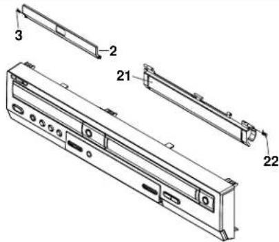 | 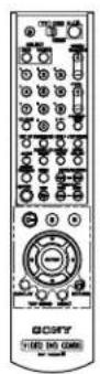 |
| SLV-D950 | 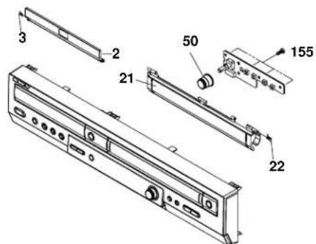 | 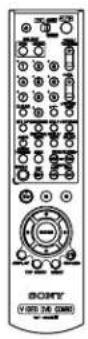 |
8-2 ELECTRICAL PARTS LIST
NOTE:
- Due to standardization, replacements in the parts list may be different from the parts specified in the diagrams or the components used on the set. - -XX, and -X mean standardized parts, so they may have some difference from the original one. • RESISTORS All resistors are in ohms. METAL: metal-film resistor METAL OXIDE: Metal Oxide-film resistor F: nonflammable \- Not all of the parts are listed. - Items marked “\*” are not stocked since they are seldom required for routine service. Some delay should be anticipated when ordering these items. - SEMICONDUCTORS In each case, u: , for example: uA...: A... , uPA... , PA... , uPB... , PB... , uPC... , PC... , uPD..., ∝PD. • CAPACITORS: uF: ∝F • COILS uH: H When indicating parts by reference number, please include the board name. The components identified by mark △ or dotted line with mark △ are critical for safety. Replace only with part number specified. Ref. No. Part No. Description Remarks DVD MAIN BOARD \*\*\*\*\*\*\*\*\*\*\*\*\* 9-885-043-18 PWB MAIN ASSY (EXCEPT D910R/D910AZ) 9-885-043-19 PWB MAIN ASSY (D910R) 9-885-043-20 PWB MAIN ASSY (D910AZ) < DIODE > DD1 1-805-013-11 DIODE DAP202K < IC > AIC2 1-805-024-11 IC (DA CONVERTER) AIC4 1-805-028-11 IC (OP AMP 4560) PIC1 1-805-030-11 IC 1563 (V REGULATOR) PIC2 9-885-037-02 IC (POSI. FIXED) RIC1 9-885-037-19 IC S5L1463A01 (ASIC) SIC1 9-885-037-18 IC S5L1455X01 (ASIC) SIC2 9-885-036-98 IC 41LV16256 (DRAM) SIC3 9-885-036-97 IC FAN8728 (MOTOR DRIVER) VIC1 9-885-037-03 IC LA73054 (VIDEO) ZIC1 9-885-043-28 IC ZR36742 (DECODER) ZIC2 9-885-036-99 IC IS42S16400A-7T (DRAM) ZIC3 9-885-050-82 IC (FLASH MEMORY) (EURO W) (D950B/D950GI/D950E/D910E/D910B) ZIC3 9-885-050-83 IC (FLASH MEMORY) (EURO E) (D910N/D910R) ZIC3 9-885-050-85 IC (FLASH MEMORY) (AZ) (D910AZ) ZIC7 1-805-027-11 IC 24C021 (EEPROM) ZIC8 1-805-022-11 IC 74VHCT125A (CMOS LOGIC)S. M. P. S. VCR MAIN
Ref. No. Part No. Description Remarks D1SS17 1-804-412-11 DIODE FIT4 D1SS19 1-804-412-11 DIODE FIT4 ZD1P02 1-804-418-11 DIODE MTZJ12B ZD1P03 1-804-417-11 DIODE MTZJ9.1B ZD1SS1 9-885-036-94 DIODE MTZJ20B ZD1SS2 1-805-265-11 DIODE MTZJ4.3B < FET > SCS11A 9-885-036-95 FET SILICONNote :
The components identified by mark △ or dotted line with mark △ are critical for safety. Replace only with part number specified. Ref. No. Part No. Description Remarks < FUSE > ▲FZ01 1-576-729-11 FUSE-RADIAL LEAD1A △FZ02 1-576-729-11 FUSE-RADIAL LEAD1A △FZ03 1-576-729-11 FUSE-RADIAL LEAD1A ▲FZ04 1-576-729-11 FUSE-RADIAL LEAD1A < IC > DIC1 1-805-039-11 IC M74HCU04 IC301 1-804-702-11 IC (VIDEO) IC501 1-804-703-11 IC (HIFI) IC604 1-804-704-11 IC (RESET) (EXCEPT D910AZ) IC604 1-804-773-11 IC (RESET) (D910AZ) IC605 1-804-432-11 IC 524C80D81 IC608 1-804-705-11 IC (POWER DETECT) (D910N/D910R/D910AZ) IC701 9-885-043-27 IC (LED DRIVER) IC802 9-885-036-96 IC BU4053BCFV (CMOS LOGIC) IC803 9-885-036-96 IC BU4053BCFV (CMOS LOGIC) (EXCEPT D910AZ) IC3S01 1-804-701-11 IC (SECAM) (D950B/D910B/D910R) IC4N01 1-805-156-11 IC MSP3417D (PQFP) (AUDIO) IC6P01 1-804-453-11 IC (PDC/OSD) (EXCEPT D910R/D910AZ) IC6P01 1-804-454-11 IC (OSD) (D910R/D910AZ) ICA811 1-805-028-11 IC 4560 (OP AMP) (EXCEPT D950B/D910B) PIC3 1-805-031-11 IC 3RD13 (V REGULATOR)VCR MAIN
Ref. No. Part No. Description RemarksNote :
The components identified by mark △ or dotted line with mark △ are critical for safety. Replace only with part number specified.- SPECIFICATIONS
- System
- Inputs and outputs
- Timer section
- General
- Supplied accessories
- SAFETY CHECK-OUT
- WARNING!!
- CAUTION:
- CAUTION
- Unleaded solder
- : LEAD FREE MARK
- SAFETY-RELATED COMPONENT WARNING!!
- TABLE OF CONTENTS
- Precautions
- General
- Disassembly and Reassembly
- Block Diagram 3-1
- PCB Diagrams
- Schematic Diagrams
- Alignment and Adjustments
- Troubleshooting 7-1
- Repair Parts List
- SAFETY PRECAUTIONS
- 2-1 General Servicing Precautions
- 2-2 Insulation Checking Procedure
- Electrostatically Sensitive Devices (ESD)
- 5-1 Disassembly
- 5-2 Assembly
- Step 1 : Unpacking
- Check your model name
- Controlling other TVs with the remote commander
- Code numbers of controllable TVs
- Notes
- Step 2 : Setting up the remote commander
- Inserting the batteries
- Using the remote commander
- Step 3 : Connecting the DVD-VCR
- Additional connection
- To a satellite or digital tuner with Line Through
- To cancel the Auto Set Up function
- Tip
- Step 4 : Setting up the DVD-VCR with the Auto Set Up function
- Step 5 : Selecting a language
- Before you start...
- Step 6 : Setting the clock
- Step 7 : Presetting channels
- RETURN
- If the picture is not clear
- Tips
- Note
- Changing/disabling programme positions
- Changing programme
- positions
- Disabling unwanted programme positions
- Changing the station names
- Setting the Canal Plus decoder
- Setting Canal Plus channels
- Basic Operations
- Playing discs DVD VCD CD DATA-CD
- To Resume playback for the current disc (Resume Play)
- Guide to the on-screen display DVD VCD CD DATA-CD
- To playback the desired title/track or chapter
- Playing a tape VHS
- 1
- 2
- To play a recently watched scene
- To skip playback
- To turn off the power while rewinding (Rewind Shut Off)
- To resume normal playback
- To set the colour system
- To use the time counter
- Recording TV programmes VHS
- To watch another TV programme while recording
- To watch a DVD while recording
- To save a recording
- To stop recording
- To check the remaining time
- Recording TV programmes using the ShowView® system (SLV-D950B only) VHS
- Daily/weekly recording
- Timer recording with VPS/PDC signals
- To watch another TV programme after setting the timer
- To use the Auto Tape Speed function
- Recording TV programmes using the timer
- VHS
- Before you start..
- 5
- 6
- Dally/weekly recording
- 3
- 4
- Recording TV programmes using DIAL TIMER (SLV-D950B only) VHS
- To return to the previous step
- To set the clock
- About the Demonstration Mode
- To activate the Demonstration Mode
- To cancel the Demonstration Mode
- Checking/changing/cancelling timer settings VHS
- When the timer settings overlap
- Advanced Hookups
- A/V Receiver hookup DVD VCD CD DATA-CD VHS
- DVD Settings and Adjustments
- Audio Setup DVD
- S-Video hookup DVD VCD DATA-CD
- Menu choices
- Screen Setup DVD
- Setting the display or sound track language DVD
- Parental Control (limiting playback by children)
- DVD
- To change the password
- To turn off the Parental Control function
- To play a disc for which Parental Control is set
- If you forget your password
- To turn off the DVD's menu
- DVD Additional Operations
- Using the DVD's menu DVD
- Zooming into a scene DVD VCD DATA-CD
- Changing the angles DVD
- Various play mode functions (Programme play, Shuffle play, Repeat play) DVD VCD CD DATA-CD
- Creating your own programme (Programme play)
- Displaying the subtitle DVD
- Playing in random order (Shuffle play)
- To return to normal play
- Changing the sound DVD VCD CD
- Playing repeatedly (Repeat play) DVD VCD CD DATA-CD
- When playing a DVD
- When playing a VIDEO CD or CD
- When playing a DATA CD (MP3 audio)
- Virtual surround setting DVD
- To cancel the setting
- Playing an MP3 audio track DATA-CD
- To play a Multi Session CD
- The Playback order of MP3 audio tracks
- Playing JPEG image files DATA-CD
- To display the selected image
- To play the Slide show
- To rotate an Image
- To zoom in an image
- To enjoy the Slide show
- To turn on/off the menu in the single image display
- To return to the "Album" display
- About JPEG Image files
- Playing VIDEO CDs with "MENU OUI/NON" functions VCD
- To return to the menu
- To play using "MENU NON"
- VCR Additional Operations
- Playing a tape with SQPB function VHS
- Quick Timer Recording VHS
- Recording stereo and bilingual programmes VHS
- In the ZWEITON (German stereo) system
- To select bilingual sound while recording
- To select stereo programme while recording
- In the NICAM system
- To extend the duration
- To cancel the duration
- To stop while recording
- To select the sound while recording
- Selecting the sound during HI-fl playback
- How sound is recorded on a video tape
- Searching using index function VHS
- To find a specific recording by scanning (Index scan)
- To search a specific recording (Index search)
- To stop searching
- Adjusting the picture (tracking) VHS
- Adjusting the tracking
- Adjusting the picture
- sharpness (Smart trilogic)
- How to connect to record on this VCR
- How to connect to a stereo system
- Additional Information
- General setup information
- Operation (when recording on this VCR)
- Before you start editing
- To stop editing
- Troubleshooting
- Title (page 35)
- Track (page 35)
- Glossary
- Chapter (page 35)
- Dolby Digital (pages 60 and 63)
- Dolby Surround (Pro Logic) (page 59)
- DTS (page 63)
- DVD (page 6)
- DVD-RW (page 6)
- DVD+RW (page 6)
- Index to parts and controls
- DVD player and VCR
- DVD player only
- Index
- Numerics
- A
- C
- □
- E
- H
- I
- J
- L
- B
- N
- F
- R
- 10
- T
- U
- y
- 7
- 2-1 CABINET AND PCB
- 2-1-1 Cabinet Top Removal 2-1-3 Ass'y Front Panel Removal
- 2-1-2 Bottom Cover Removal
- 2-1-4 Function PCB Removal
- 2-3-1 Top View
- 2-4-1 Holder FL Cassette Ass'y Removal
- 2-4-2 Lever FL Door Removal
- 2-4-3 Slider FL Drive, Gear FL Cam Removal
- 2-4-4 Lever FL Arm Ass'y Removal
- 2-4-5 Gear Worm Wheel Removal
- 2-4-6 Cable Flat Removal
- 2-4-7 Motor Loading Ass'y Removal
- 2-4-8 Bracket Gear, Gear Joint 2, 1 Removal
- Assembly:
- 2-4-9 Gear Loading Drive, Slider Cam, Lever Load S, T Ass'y Removal
- 2-4-10 Gear Loading Drive, Slider Cam, Lever Load S, T Ass'y Assembly
- 2-4-11 Lever Pinch Drive, Lever Tension Drive Removal
- 2-4-12 Lever Tension Ass'y, Band Brake Ass'y Removal
- Note:
- 2-4-13 Lever Brake S, T Ass'y Removal
- 2-4-14 Gear Idle Ass'y Removal
- 2-4-15 Disk S, T Reel Removal
- 2-4-16 Holder Clutch Ass'y Removal
- 2-4-17 Lever Up Down Ass'y, Gear Center Ass'y Removal
- 2-4-18 Guide Cassette Door Removal
- 2-4-19 Lever Unit Pinch Ass'y, Plate Joint, Spring Pinch Drive Removal
- 2-4-20 Lever #9 Guide Ass'y Removal
- 2-4-21 FE Head Removal
- 2-4-22 ACE Head Removal
- 2-4-23 Slider S, T Ass'y Removal
- 2-4-24 Plate Ground Deck, Cylinder Ass'y Removal
- 2-4-25 Belt Pulley Removal
- 2-4-26 Motor Capstan Ass'y Removal
- 2-4-27 Post #8 Guide Ass'y Removal
- 2-4-28 Level Head Cleaner Ass'y Removal (Optional)
- 2-4-29 How to Eject the Cassette Tape (If the unit does not operate on condition that is inserted into housing Ass'y)
- 2-5 THE TABLE OF CLEANING, LUBRICATION AND REPLACEMENT TIME ABOUT PRINCIPAL PARTS
- 2-6-2 Ass'y P/U Deck Removal
- 2-6-2 Assy P/U Deck Removal
- 2-6-3 Housing Ass'y Removal
- 2-6-4 Sub Chassis Removal
- 2-6-5 Ass'y Brkt Deck Removal
- BLOCK DIAGRAM
- 4-1 VCR MAIN
- COMPONENT SIDE
- 4-2 DVD MAIN
- 4-4 FUNCTION
- 4-5 DIAL-TIMER (SLV-D950B/D950E/D950GI/D910AZ Only)
- VCR Main PCB
- DVD Main PCB
- 5-2 POWER DRIVE
- 5-4 A2/NICAM
- 5-5 AUDIO/VIDEO
- 5-7 INPUT-OUTPUT
- 5-9 SYSCON
- 5-11 SECAM (SLV-D950B/D910B/D910R Only)
- 5-13 DVD SERVO
- 5-14 DVD AUDIO/VIDEO
- 6-1 VCR ADJUSTMENT
- 6-1-1 Reference
- 6-1-1(a) Location of adjustment button of remote control
- 6-1-2 Head Switching Point Adjustment
- 6-1-3 NVRAM Option Setting
- 6-2-2 Skew Adjustment
- 6-2-2(b) SKEW Adjustment Method
- 6-3-1 Tape Transport System and Adjustment Locations
- 6-3-2 Tape Transport System Adjustment
- ACE Head Assembly Adjustment
- a. ACE HEAD HEIGHT ADJUSTMENT
- b. ACE HEAD TILT ADJUSTMENT
- c. AUDIO AZIMUTH ADJUSTMENT
- d. ACE HEAD POSITION (X-POINT) ADJUSTMENT
- Linearity adjustment (Guide roller S, T adjustment)
- Check Transitional Operation from RPS to Play
- Envelope Check
- Tape Wrinkle Check
- 6-3-3 Reel Torque
- TROUBLESHOOTING
- 8-1-1 Cabinet Assembly
- 8-2 ELECTRICAL PARTS LIST
- M. P. S. VCR MAIN
- Note :
- VCR MAIN
Brand : SONY
Model : SLV-D910R
Category : DVD Player / VCR