URCC115-SS81A - Ice Maker U-Line - Free user manual and instructions
Find the device manual for free URCC115-SS81A U-Line in PDF.


| Product Type | Undercounter Ice Maker |
| Brand | U-Line |
| Model | URCC115-SS81A |
| Ice Production | Up to 28 lbs (12.7 kg) per day |
| Storage Capacity | 12 lbs (5.4 kg) |
| Ice Shape | Clear, crescent cubes |
| Width | 14 7/8 inches (37.8 cm) |
| Depth | 16 1/2 inches (41.9 cm) |
| Height | 33 7/8 inches (86.0 cm) |
| Net Weight | 75 lbs (34 kg) |
| Power Supply | 115 V, 60 Hz, 2 A |
| Energy Consumption | 320 kWh/year (estimated) |
| Installation | Undercounter, built-in |
| Controls | Electronic touch panel with LED indicators |
| Cleaning Cycle | Automatic self-cleaning function |
| Venting | Front grille ventilation |
| Leveling | 4 adjustable leveling legs |
| Water Connection | Direct water line connection (not included) |
| Filter | Optional water filter (compatible with U-Line filter) |
| Certifications | ETL listed, Energy Star qualified |
| Warranty | 3 years limited parts and labor |
| Manufacturer | U-Line Corporation, Milwaukee, WI |
Frequently Asked Questions - URCC115-SS81A U-Line
User questions about URCC115-SS81A U-Line
0 question about this device. Answer the ones you know or ask your own.
Ask a new question about this device
Download the instructions for your Ice Maker in PDF format for free! Find your manual URCC115-SS81A - U-Line and take your electronic device back in hand. On this page are published all the documents necessary for the use of your device. URCC115-SS81A by U-Line.
USER MANUAL URCC115-SS81A U-Line
USER GUIDE & SERVICE MANUAL
natural_image
Modern kitchen interior with white walls, black brick wall, and wooden flooring (no visible text or symbols)Model: URCC115-SS81A
Click on any section below to jump directly there
Table of Contents
| Intro | Product Liability |
| R600a Specifications | |
| Safety | System Diagnosis Guide |
| Safety and Warning | Compressor Specifications |
| Disposal And Recycling | Control Operation - Service |
| Thermistor | |
| Installation | Warranty |
| Environmental Requirements | |
| Electrical | |
| Cutout & Product Dimensions | |
| Side by Side Installation | |
| Water Hookup | |
| Drain | |
| General Installation | |
| Grille Installation | |
| Door Swing | |
| Door Adjust |
Maintenance
Cleaning
Cleaning Condenser
Extended Non-Use
Operating Instructions
First Use
Control Operation
Ice
Service
Troubleshooting
Wire Diagram
WELCOME TO U-LINE
Congratulations on your U-Line commercial purchase. Your product comes from a company with over five decades of premium modular ice making, refrigeration, and wine preservation experience. U-Line continues to be the American leader in refrigeration, delivering versatility and flexibility for multiple applications, including: residential, commercial, outdoor and marine use. U-Line's commercial collection includes reach-in refrigerators and freezers, dispensers, ice machines, undercounter refrigeration and wine, back bar refrigeration, blast chillers and shock freezers, base refrigerators and freezers, and pizza and food prep tables.
U-Line has captivated those who have an appreciation for the finer things combined with exceptional functionality, style, inspired innovations, and attention to even the smallest details. We are known and respected for our unwavering dedication to product design, quality, and selection. Headquartered in Milwaukee, Wisconsin, U-Line has shipped product to five continents for over two decades and is proud to have the opportunity to ship to you.
U-LINE — RIGHT PRODUCT. RIGHT PLACE. RIGHT TEMPERATURE.®
PRODUCT INFORMATION
Looking for additional information on your product? User Guides, Spec Sheets, CAD Drawings, and Product Warranty information are available digitally on u-line.com
PROPERTY DAMAGE / INJURY CONCERNS
In the unlikely event property damage or personal injury is suspected related to a U-Line product, please take the following steps:
- U-Line Customer Care must be contacted immediately at +1.414.354.0300.
- Service or repairs performed on the unit without prior written approval from U-Line is not permitted. If the unit has been altered or repaired in the field without prior written approval from U-Line, claims will not be eligible.
GENERAL INQUIRIES
U-Line Corporation
8900 N. 55th Street
Milwaukee, Wisconsin 53223 USA
Monday - Friday 8:00 am to 4:30 pm CST
T: +1.414.354.0300
Email: sales@u-line.com
u-line.com




CONNECT WITH US
SERVICE & PARTS ASSISTANCE
Monday - Friday 8:00 am to 4:30 pm CST
T: +1.414.354.0300
Service Email: onlineservice@u-line.com
Parts Email: onlineparts@u-line.com
Safety and Warning
NOTICE
Please read all instructions before installing, operating, or servicing the appliance.
Use this appliance for its intended purpose only and follow these general precautions with those listed throughout this guide:
SAFETY ALERT DEFINITIONS
Throughout this guide are safety items labeled with a Danger, Warning, or Caution based on the risk type:

DANGER
Danger means that failure to follow this safety statement will result in severe personal injury or death.

WARNING
Warning means that failure to follow this safety statement could result in serious personal injury or death.

CAUTION
Caution means that failure to follow this safety statement may result in minor or moderate personal injury, property, or equipment damage.

DANGER
This unit contains R600a (Isobutane) which is a flammable hydrocarbon. It is safe for regular use. Do not use sharp objects to expedite defrosting. Do not service without consulting the "R600a specifications" section included in the User Guide. Do not damage the refrigerant circuit.

WARNING
Service must be done by factory authorized service personnel. Any parts shall be replaced with like components. Failure to comply could increase the risk of possible ignition due to incorrect parts or improper service.
CALIFORNIA PROPOSITION 65
This product contains chemicals known to the state of California to cause cancer and birth defects or other reproductive harm.
www.P65warnings.CA.gov

CAUTION
This equipment is to be installed with adequate backflow protection to comply with applicable federal, state and local codes.
Disposal and Recycling

DANGER
RISK OF CHILD ENTRAPMENT. Before you throw away your old refrigerator or freezer, take off the doors and leave shelves in place so children may not easily climb inside.
If the unit is being removed from service for disposal, check and obey all federal, state, and local regulations regarding the disposal and recycling of refrigeration appliances, and follow these steps completely:
- Remove all consumable contents from the unit.
- Unplug the electrical cord from its socket.
- Remove the door(s)/drawer(s).
Environmental Requirements
This model is intended for indoor/interior applications only and is not to be used in installations that are open/exposed to natural elements.
This unit is designed to operate between 50°F (10°C) and 100°F (38°C). Higher ambient temperatures may reduce the unit's ability to reach low temperatures and/or reduce ice production on applicable models.
For best performance, keep the unit out of direct sunlight and away from heat generating equipment.
In climates where high humidity and dew points are present, condensation may appear on outside surfaces. This is considered normal. The condensation will evaporate when the humidity drops.

CAUTION
Damages caused by ambient temperatures of 40^ F ( 4^ C) or below are not covered by the warranty.
Electrical
WARNING
SHOCK HAZARD — Electrical Grounding Required. Never attempt to repair or perform maintenance on the unit until the electricity has been disconnected.
Never remove the round grounding prong from the plug and never use a two-prong grounding adapter.
Altering, cutting or removing power cord, removing power plug, or direct wiring can cause serious injury, fire, loss of property and/or life, and will void the warranty.
Never use an extension cord to connect power to the unit.
Always keep your working area dry.
NOTICE
Electrical installation must observe all state and local codes. This unit requires connection to a grounded (three-prong), polarized receptacle that has been placed by a qualified electrician.
The unit requires a grounded and polarized 115 VAC, 60 Hz, 15A power supply (normal household current). An individual, properly grounded branch circuit or circuit breaker is recommended. A GFCI (ground fault circuit interrupter) is usually not required for fixed location appliances and is not recommended for your unit because it could be prone to nuisance tripping. However, be sure to consult your local codes.
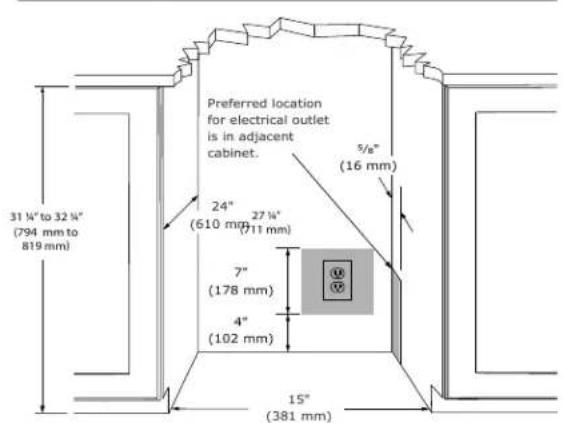
See CUTOUT & PRODUCT DIMENSIONS for recommended receptacle location.
Cutout & Product Dimensions
PREPARE SITE
Your product has been designed for either free-standing or built-in installation. When built-in, your unit does not require additional air space for top, sides, or rear. However, the front grille must NOT be obstructed, and clearance is required for an electrical connection in the rear.

CAUTION
Unit can NOT be installed behind a closed cabinet door.
If you would like to align the face of the unit with other adjacent cabinet doors, you may need to alter the wall just behind the drain connection on the unit to accommodate the drain.
CUTOUT DIMENSIONS
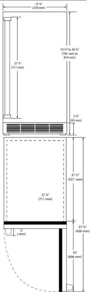
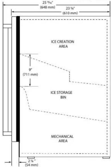
PRODUCT DIMENSIONS
REAR
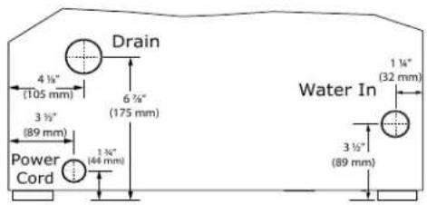
FRONT
TOP
SIDE
Side-by-Side Installation
OTHER SITE REQUIREMENTS
Side-by-Side Installation
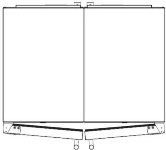
Units must operate from separate, properly grounded electrical receptacles placed according to each unit's electrical specifications requirements.
Cutout width for a side-by-side installation is the total of the widths listed under Cutout Dimensions in each unit's Installation Guide. Each door can be opened individually (one at a time) without interference.
natural_image
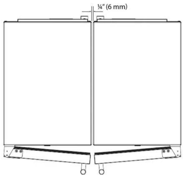
Technical line drawing of a rectangular frame with two vertical panels and mounting brackets (no text or symbols)However, to ensure unobstructed door swing (opening both doors at the same time), 1/4" (6.4 mm) of space needs to be maintained between the units.
Hinge-by-Hinge Installation (Mullion)
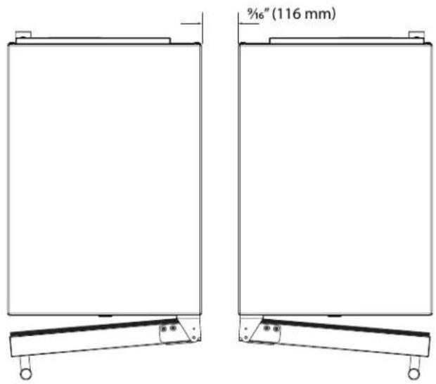
When installing two units hinge-by-hinge, 13/16" (22 mm) is required for integrated models. Additional space may be needed for any knobs, pulls or handles installed.
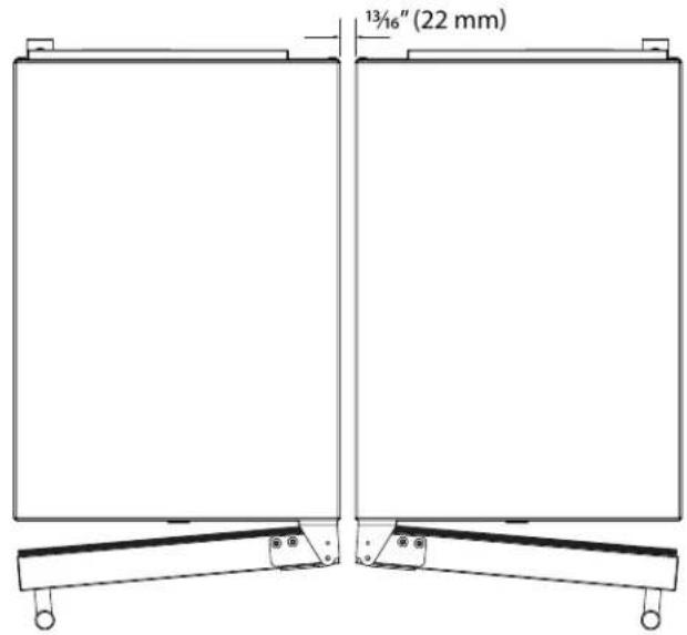
Stainless steel models which include the standard stainless handle will require 4-9/16" (116 mm) to allow both doors to open to 90° at the same time.
Water Hookup
WATER SUPPLY

CAUTION
Observe and follow all local building codes when installing this appliance.
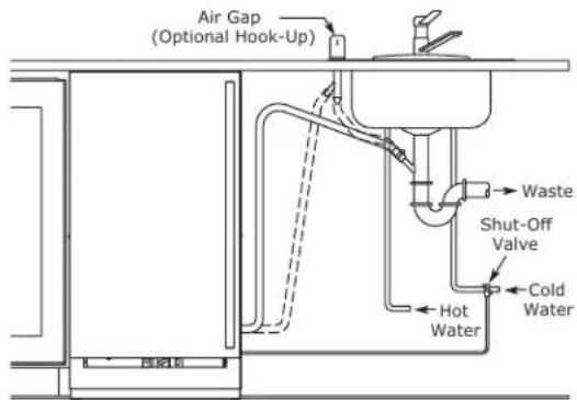
This ice machine must be connected to a potable cold water supply line. delivering water pressure between a minimum of 20 psi and a maximum of 120 psi.
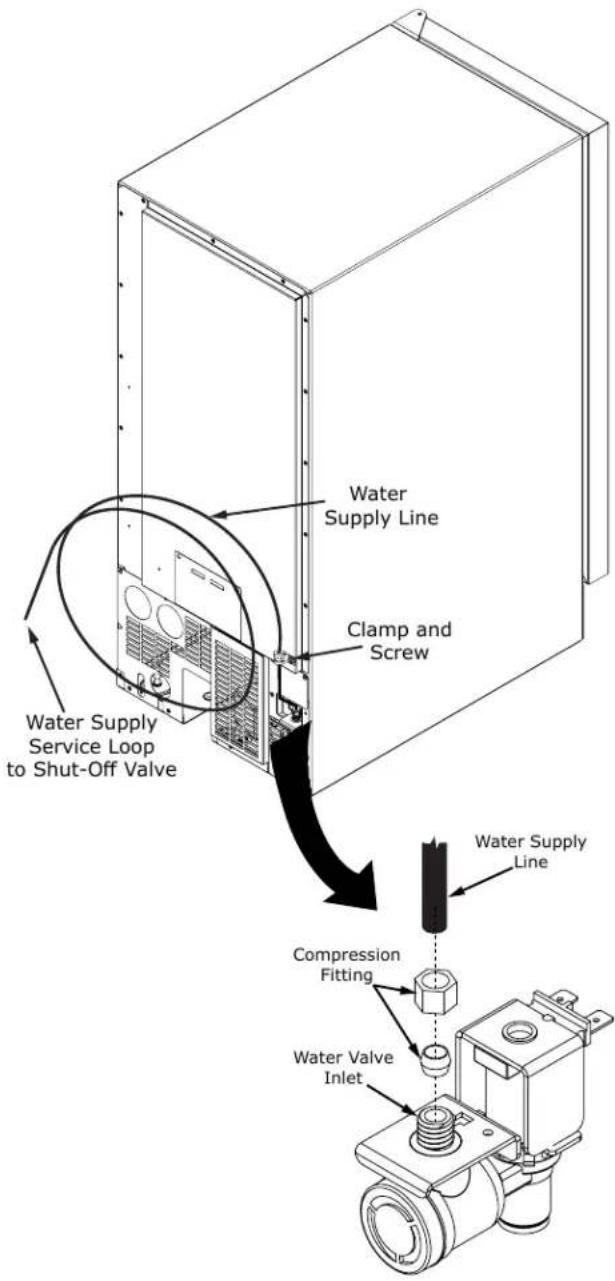
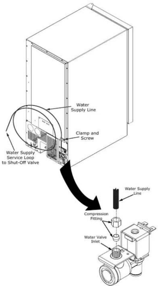
Use 1/4" copper tubing for your water supply which is available at any local hardware or plumbing supply store. Route the 1/4" copper tubing to suit your installation being sure not to kink the tubing. Purchase enough copper tubing length to allow a coil to be formed behind the unit for a "service loop" which will allow the appliance to be pulled out from the installation for servicing or cleaning. (See Figure 11). Connect the copper tubing to the "top side" of a cold water pipe to prevent the ice-maker from plugging with sediment.
A shutoff valve is recommended on the water supply line to ease servicing the appliance. NOTE: A SELF-PIERCING TYPE VALVE IS NOT RECOMMENDED as they are prone to clogging with sediment which will create pressure drop reducing the water supply to the unit.
Connect the copper tubing water supply to the water valve inlet with a 14 " compression nut fitting.
IMPORTANT: Secure the water supply line to the back of the cabinet with the screw and strain relief clamp provided in the corner of the back panel.
Make certain all connections are watertight after installation. Form the tubing so that it will not vibrate against the cabinet body or kink when your appliance is moved in and out of position.
This ice machine is designed to make clear ice from the majority of water sources on a daily basis. If your results are unsatisfactory, your water may need to be filtered or treated. A water specialist can recommend proper water treatment.

CAUTION
To prevent water leaks:
- The water line fitting is to be used with copper tubing only. Do not use with plastic tubing.
- Do not use any thread sealers on this water line fitting.
NOTE:
Reverse osmosis (RO) water, softened water, and de-ionized water are not recommended as they can adversely affect the quality and quantity of the ice.
Drain
DRAIN CONNECTION

CAUTION
The floor drain must be large enough to accommodate drainage from all attached drains. Follow these guidelines when installing drain lines to prevent water from flowing back into the ice maker storage bin and/or potentially flowing onto the floor, which may result in personal injury or property damage
NOTICE
Drain can NOT be located directly below the unit. Unit has a solid base that will not allow the unit to drain below itself.
There is a possibility that hose connections may have loosened during shipment.
Verify all connections and fittings are free from leaks.

CAUTION
This equipment is to be installed with adequate backflow protection to comply with applicable federal, state and local codes

CAUTION
Failure to connect water supply or drain line connections properly can result in personal injury and property damage. Gravity drain connections must be routed downward from the rest of the unit at the rate of 1/4" per foot (1 cm per 50 cm).
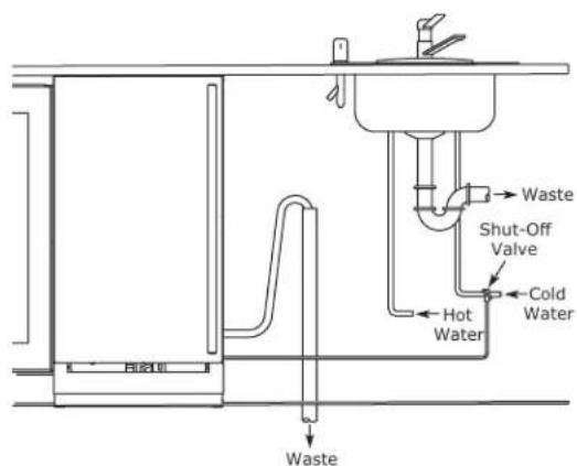
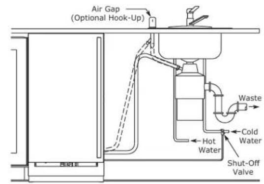
Drain line coiled and secured to the back of the cabinet. Uncoil, route to an appropriate drain, and and cut to length.
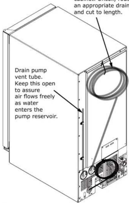
NOTICE
The maximum lift for the drain pump is 10 feet. This must be done as close to the rear of the unit as possible.
General Installation
LEVELING INFORMATION
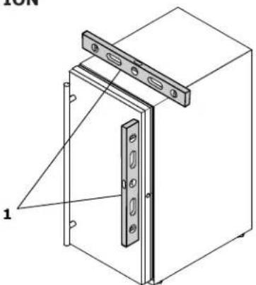
- Use a level to confirm the unit is level. Level should be placed along top edge and side edge as shown.
natural_image
Technical line drawing of a mechanical cabinet or enclosure with mounting holes and a door (no text or symbols)- If the unit is not level, adjust the legs on the corners of the unit as necessary.
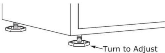
- Confirm the unit is level after each adjustment and repeat the previous steps as needed.
INSTALLATION TIP
If the room floor is higher than the floor in the cutout opening, adjust the rear legs to achieve a total unit rear height of 18 " (3 mm) less than opening's rear height. Shorten the unit height in the front by adjusting the front legs. This allows the unit to be gently tipped into the opening. Readjust the front legs to level the unit after it is correctly positioned in the opening.
INSTALLATION
- Plug in the power/electrical cord.
- Gently push the unit into position. Be careful not to entangle the cord or water and drain lines, if applicable.
- Re-check the leveling, from front to back and side to side. Make any necessary adjustments. The unit's top surface should be approximately 18 " (3 mm) below the countertop.
- Remove interior packing material and wipe out the inside of the unit with a clean, water-dampened cloth.
Grille Installation
REMOVING AND INSTALLING GRILLE

WARNING
Disconnect electric power to the unit before removing the grille.
When using the unit, the grille must be installed.

WARNING
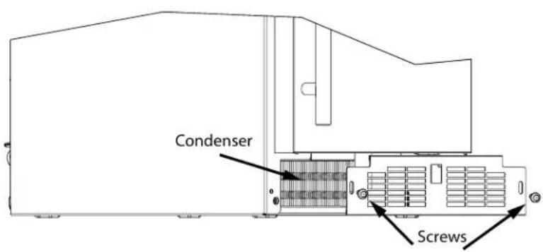
Do NOT touch the condenser fins. The condenser fins are SHARP and can be easily damaged.
Removing the grille
- Disconnect power to the unit.
- Remove the two screws.
- Remove grille from unit.
Installing the grille
- Align cabinet and grille holes and secure, but do not over tighten grille screws.
- Reconnect power to the unit.
Door Swing
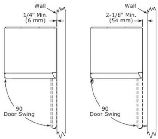
Units have a zero clearance for the door to open 90°, when installed adjacent to cabinets.
Stainless Steel and black and white models require 2-1/8" (54 mm) door clearance to accommodate the handle if installed next to a wall.
Integrated models require 1/4" (6 mm) clearance if installed next to a wall. Allow for additional space for any knobs or pulls installed on the integrated panel/frame.
Door Adjustments
DOOR ALIGNMENT AND ADJUSTMENT
Align and adjust the door if it is not level or not sealing properly. If the door is not sealed, the unit may not cool properly, or excessive frost or condensation may form in the interior.
NOTICE
Properly aligned, the door's gasket should be firmly in contact with the cabinet all the way around the door (no gaps). Carefully examine the door's gasket to ensure that it is firmly in contact with the cabinet. Also make sure the door gasket is not pinched on the hinge side of the door.

CAUTION
Do not attempt to use the door to raise or pivot your unit. This would put excessive stress on the hinge system.
Alignment and Adjustment Procedure
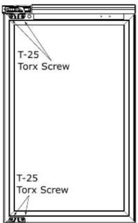
- Open door and remove gasket near the hinges.
- Using a T-25 Torx bit, loosen each pair of Torx head screws both the upper and lower hinge plates.
- Square and align door as necessary.
- Tighten Torx head screws on hinge.
- Reinstall gasket into the channel starting at the corner.
REVERSING THE DOOR
- Open door.
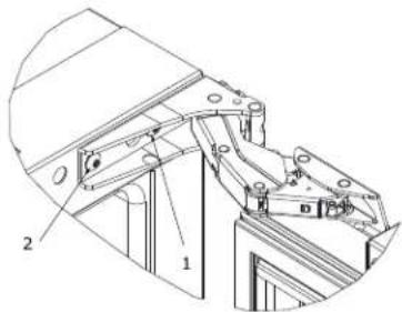
- Using T-25 Torx bit loosen screw #1 and remove screw #2 on top and bottom hinge. Slide and remove the door from the unit.
-
Using #2 Phillips bit, remove the 4 underlying screws. Reinstall the screws and caps on the opposite side.
-
Partially install screw #1 in the outer most holes on top and bottom. Rotate door 180o, align hinge over screw #1 and slide/seat into position. Reinstall screw #2 on top and bottom. Tighten both screws and install hinge cover.
Reposition Magnet
- Remove magnet by taking out 2 screws.
- Install magnet at other end of door.
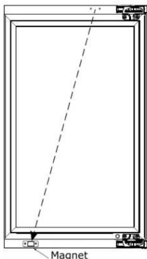
Align and adjust the door:
Align and adjust the door (see DOOR ALIGNMENT AND ADJUSTMENT).
First Use
Initial startup requires no adjustments. See CONTROL OPERATION section for more details.
NOTICE
Discard the ice produced during the first two or three hours of operation to avoid possible dirt or scale that may dislodge from the water line.
When plugged in, the unit will begin operating under the factory default settings. If the unit was turned off during installation, simply press ⏻ and the unit will immediately switch on. To turn the unit off, press ⏻ and release.
Control Operation

Control Function Guide
| Function | Command | Notes |
| ON/OFF | Press 🎨 and release. | Unit will immediately turn ON or OFF. |
| Enable Sabbath Mode | Press 🎨 and hold for 5 seconds and release. | The ^0F / ^0C symbol will flash briefly after 5 seconds. Interior light and display will go dark and remain so until user resets mode - unit continues to operate. |
| Disable Sabbath Mode | Press 🎨 and release. | Display and interior light return to normal operation. |
| Silent Mode (ice production suspended for 3 hours) | Hold ▼ and 🔊. | Display will count down the hours: H, 2H, 1H |
| Clean Mode | See "Cleaning" section | |
| Showroom Mode | Hold △ and 🔊 for 5 seconds. | The ^0F / ^0C symbol will flash. Display will be lit and interior light will function. Unit will not cool. Repeat command to return to normal operation. |
Door Alert Notification
When the door is left open for more than 30 minutes:
• A tone will sound for several seconds every minute
- dr: will appear in display
- Close door to silence alert and reset
BrightShield™

This model includes BrightShield™ with VvV™ Antimicrobial Light Technology.
BrightShield™
- Kills* and prevents the growth of viruses, bacteria, fungi, yeasts, mold, and mildew
- Provides continuous antimicrobial action to keep surfaces clean
• Is approved for continuous use around people, pets, & plants
• Reduces odors caused by bacteria, fungi, yeasts, mold, and mildew - Creates a cleaner environment for food, beverages, & ice
* Testing on a non-enveloped virus (MS2 bacteriophage) showed a 97.12% reduction in controlled laboratory testing in 8 hours on hard surfaces. Testing on SARS-CoV-2 (enveloped virus) showed a 98.45% reduction in controlled laboratory testing in 4 hours on hard surfaces. Testing on MRSA E. coli showed 90%+ reduction in controlled laboratory testing in 24 hours on hard surfaces. Results may vary depending on the amount of light that is reaching the surfaces in the space where the product is installed and the length of time of exposure. Use of Vyv™ Antimicrobial Light Technology is not intended to replace manual cleaning and disinfection practices.
BrightShield™ is most effective when used continuously. Your unit is factory-set to use BrightShield™ lighting whenever the door is closed and standard bright white when the door is open. See Control Operations sections for details and other options.
For more information about BrightShield™ visit www.u-line.com.
For more information about Vv ^TM Antimicrobial Light Technology visit www.vyv.tech.com
ICE
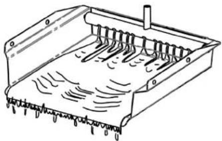
Your ice machine is unique in how it forms ice with fractional freezing to form a slab of ice that is clear and has less dissolved solids than the water from which it is produced. This is accomplished by running water over the cold evaporator plate which gradually freezes the water to produce the ice slab. Pure water freezes first, leaving the dissolved solids in the residual reservoir water.
natural_image
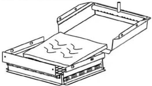
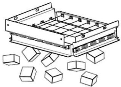
Technical line drawing of a mechanical component with spring-like grooves and internal channels (no text or symbols)When the ice slab reaches the correct thickness, the ice sheet is released and slides onto the grid cutter. There, the ice slab is cut into cubes by the grid cutter's heated wires. The water containing the dissolved minerals is drained after each freezing cycle. Fresh water enters the machine for the next ice making cycle.
natural_image
Technical line drawing of a mechanical device with internal components and no visible text or symbolsThe ice machine will keep producing ice until the ice machine's bin is full, resuming automatically as needed. The ice bin is not refrigerated, and some melting will occur by design to preserve the ice quality and clarity. Allow your ice machine to run for 24-48 hours to accumulate ice.
The bin level sensor is located in the ice bin, it senses when the ice supply is low or full and starts or stops the ice-making process accordingly.
natural_image
Technical line drawing of a mechanical assembly with scattered 3D cubes (no text or symbols)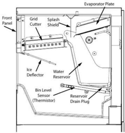
ICE PRODUCTION
In normal mode, the ice machine will produce up to 39 pounds (17.7 kg) of clear ice in a 24-hour period when installed in a 72°F ambient with a 55°F water supply.
Note:
"Initial" ice production and ice accumulated in the storage bin will vary significantly. This is normal. During the first 24-hours of operation the unit will produce up to 39 lbs of ice at the above ambient and water temperatures, but when starting with an empty ice storage bin, ice accumulation may only be 18 lbs. By design, the ice storage bin is maintained at a temperature slightly above freezing to allow the stored ice to slowly melt, to preserve the ice quality and clarity and assure a constant supply of fresh ice. As ice is accumulated in the bin, the ice production rate will over come the ice melt and the storage bin will fill to capacity.
NEW SOUNDS
The ice machine will make sounds that are different than your household refrigerator. The ice production process creates noises such as ice falling onto hard surfaces, water cascading across the evaporator, and valves opening and closing. Below are some of the sounds you may hear:
Buzzing - water valve opens to fill water reservoir.
Rattling - water flowing through water line.
Splashing - water flowing over evaporator plate and into reservoir.
A "Thud" - ice slab sliding down onto the grid cutter.
Clicks - ice cubes falling into the ice storage bin.
Gurgling - refrigerant flowing in the ice machine.
Air - the condenser fan.
Cleaning
Homes with poor water quality or high clear ice usage might require more frequent cleaning.
To clean your ice machine you will need to purchase a "nickel safe" ice maker cleaner.
CAUTION
Use only manufacturer-approved ice machine cleaner and follow all label warnings and directions. Incorrect chemical usage, and any damage that may result, is not covered by warranty.
Order ice machine cleaner online:
www.u-line.com
Part # 80-55667-00
A "CLEAN" reminder will occur every 6 months to remind you that it may be time to clean your appliance. Over time mineral build up on the cold evaporator plate can occur which can adversely affect the quality of your ice. This build-up is dependent on your water source and usage. Normal ice production will continue while the "CLEAN" reminder is displayed. When reset, the "CLEAN" reminder will reset and not occur for another 6 months. If you choose to clean the appliance at this time, see the options menu section below.
Clean mode:
To ensure maximum performance and ice quality, it is recommended to clean your ice machine once every six months. This simple cleaning routine will also ensure water and energy use continues at optimum efficiency.
To Clean Your Ice Machine:
- Turn the ice machine off by pressing and holding the "ON/OFF" icon for 3 seconds.
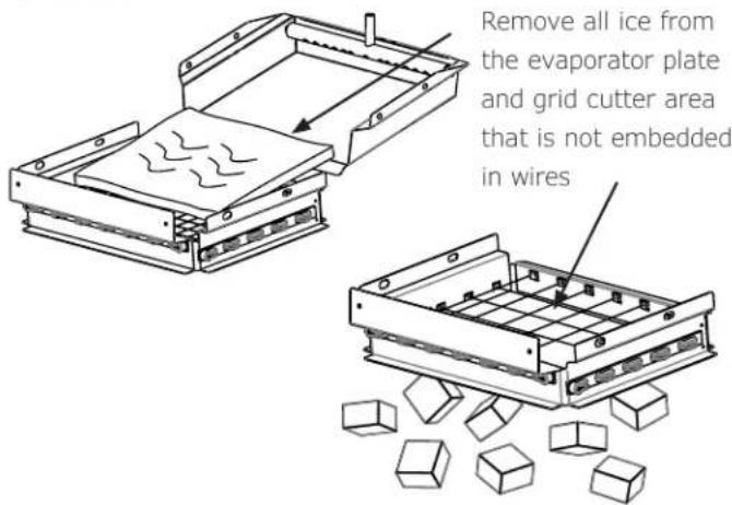
- Remove all ice from the ice maker including from the evaporator and grid cutter.
CAUTION
Forcing ice through the grid cutter will break the grid cutter wires.
DRAIN PLUG
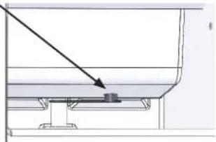
- Drain the water from the water reservoir by removing the black plug from the bottom of the fresh water reservoir.
natural_image
Pure technical diagram showing a mechanical assembly with no visible text, numbers, or symbols
- After the water is drained, replace the plug in the bottom of the reservoir.
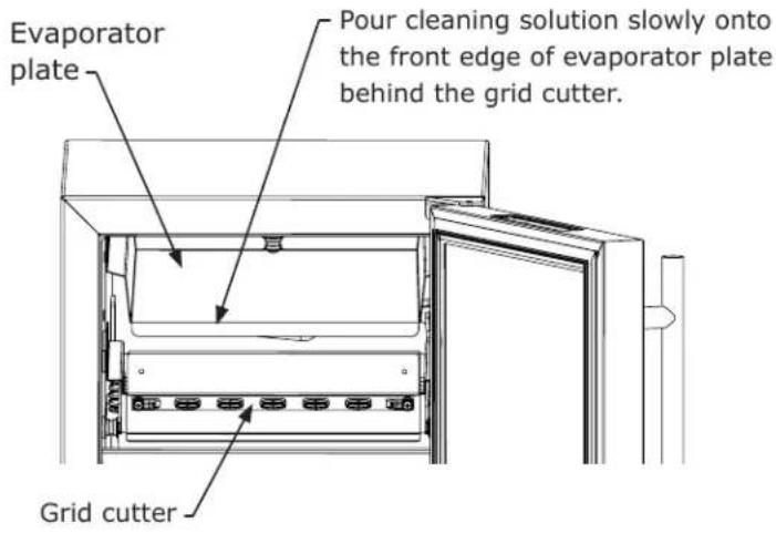
- Add cleaning solution to the evaporator plate - refer to your cleaning solution instructions to determine the proper amount of solution to add based on 2 quarts (1.9 liters) of water.
- Turn the ice machine on
- On the control, turn on clean mode by holding for 5 seconds.
- Your ice maker will fill with water and circulate over the evaporator for two 15-minute cycles then will resume normal production.
- Remove the first 2-3 new batches of ice from your ice maker before using.
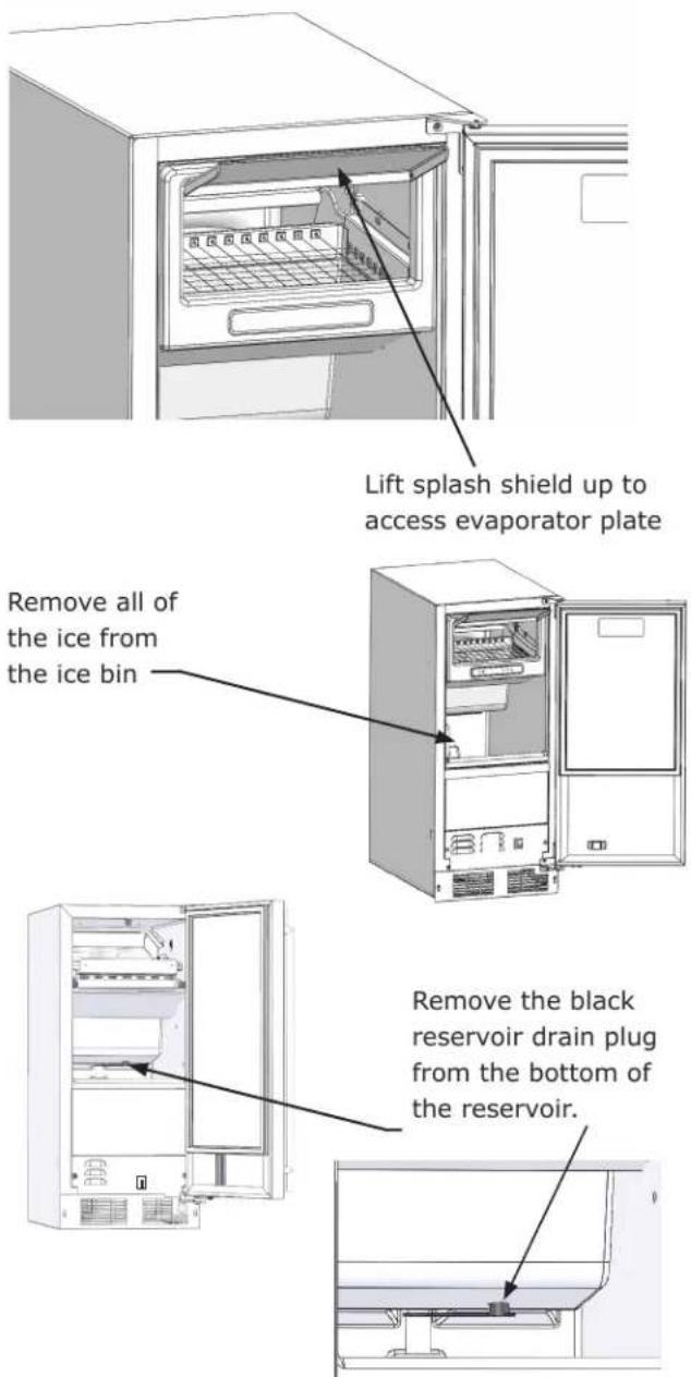
Lift splash shield up to access evaporator plate. Pour the cleaning solution slowly on the evaporator plate so it flows down into the fresh water reservoir.
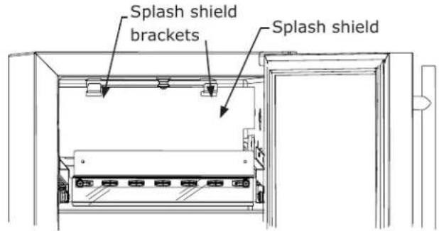
Replace the splash shield if removed.
After the cleaning cycle is completed, verify that all build-up has been removed. If not, repeat the clean cycle procedure.
CABINET
The painted cabinet can be washed with a mild soap and water and thoroughly rinsed with clear water. NEVER use abrasive scouring cleaners.
EXTERIOR
Routine cleaning of the stainless steel surfaces will serve to greatly extend the life of your product by removing contaminants. This is especially important in coastal areas which can expose the stainless to severe contaminants such as halide salts (sodium chloride).
It is strongly recommended to periodically inspect and thoroughly clean crevices, weld points, under gaskets, rivets, bolt heads, and any locations where small amounts of liquid could collect, become stagnant, and concentrate contaminants. Additionally, any mounting hardware that is showing signs of corrosion should be replaced.
INTERIOR
Wash interior compartment with mild soap and water. Do NOT use an abrasive cleaner, solvent, polish cleaner, undiluted detergent or chlorine based cleaners.
Cleaning Condenser
INTERVAL - EVERY SIX MONTHS
To maintain operational efficiency, keep the front grille free of dust and lint, and clean the condenser when necessary. Depending on environmental conditions, more or less frequent cleaning may be necessary.

WARNING
Disconnect electric power to the unit before cleaning the condenser.

WARNING
DO NOT touch the condenser fins. The condenser fins are SHARP and can be easily damaged.
NOTICE
DO NOT use any type of cleaner on the condenser unit.
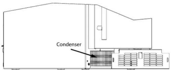
- Remove the grille. (See GRILLE INSTALLATION).
- Clean the condenser coil using a soft brush with a "combing" action or vacuum cleaner. Do not touch the condenser coil.
- Install the grille.
Extended Non-Use
If the ice machine is moved, not used for an extended period of time, or will be in an area that will be near freezing temperatures, it is necessary to remove any remaining water in the ice-making system.

CAUTION
This ice machine must have all water drained and removed to prevent ice machine damage as well as possible water damage to the surrounding area in freezing conditions. These damages are not covered under warranty.

CAUTION
Do not use any type of anti-freeze or other solution as a substitution for properly draining the ice machine.

WARNING
Risk of electrical shock or personal injury could occur due to moving components, if machine compartment access cover is removed before unplugging the ice machine.
CLEAN THE ICE MACHINE
Cleaning the ice machine will help prevent mold and mildew growth as well as sanitize the ice machine for storage or when it is put back into service. (SEE CLEANING SECTION OF THIS GUIDE)
WINTERIZATION

CAUTION
If the unit will be exposed to temperatures of 40^ F ( 5^ C) or less, these steps must be followed. Draining and Removing Water from the Ice-Making System
- Turn off the water supply to the ice machine.
- Disconnect the water supply fitting at the inlet of the water valve.
- Change the electronic control to the "CLEAN" position for approximately one (1) minute. This will energize and open the water valve and remove most of the water from the water valve and the water valve's outlet water line to the reservoir.
- Change the electronic control to the "OFF" position. This will energize and open the drain valve to drain the reservoir and the ice machine drain system.
- Unplug the ice machine from the electrical outlet.
- Remove the access cover from the rear of the ice machine.
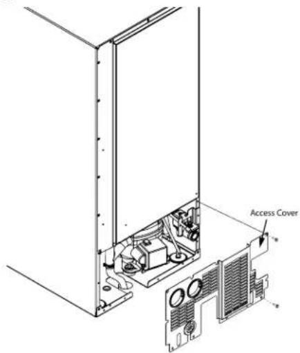
- Disconnect the water valve's outlet water line to the reservoir and drain the remaining water left in the water line trap area.
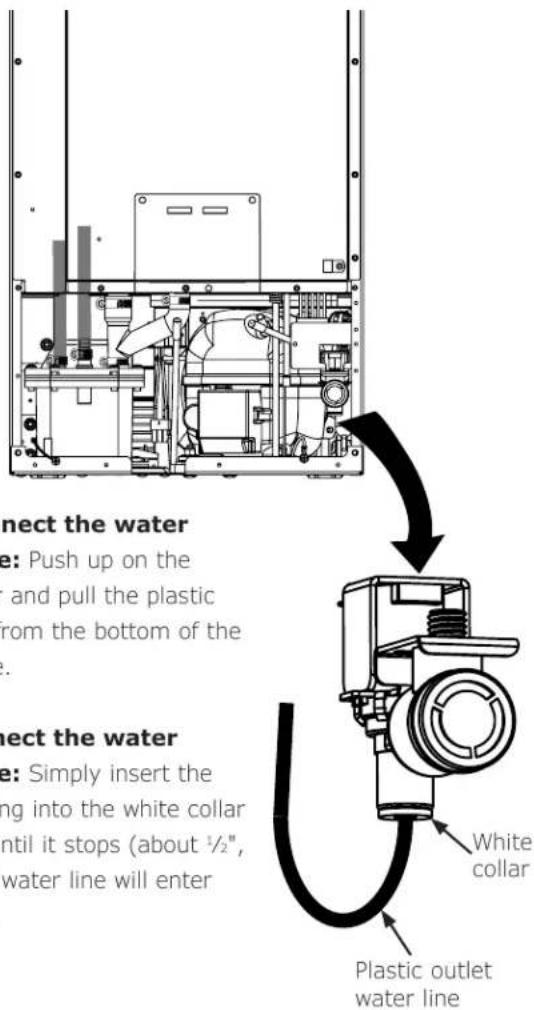
To disconnect the water outlet line: Push up on the white collar and pull the plastic water line from the bottom of the water valve.
To reconnect the water outlet line: Simply insert the plastic tubing into the white collar and push until it stops (about 12 ", 12 mm, of water line will enter the valve).
- Reconnect the water valve outlet water line.
- Reinstall the ice machine's access cover.
- Clean and dry the ice machine's storage bin.
- Prop the door open for air circulation to prevent mold and mildew.
- Leave the water supply line disconnected or reconnect the supply line and leave it shut off. Do NOT turn the water on and allow water to enter back into the water valve.
- Install the winterization plug in the water drain hole inside the ice bin.
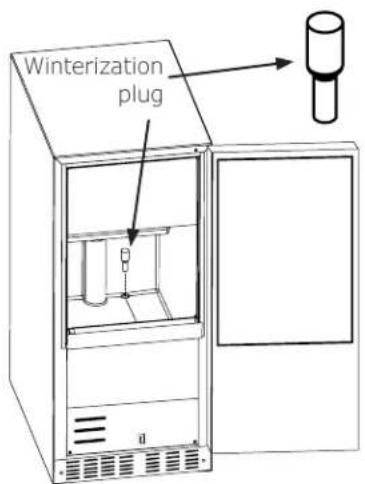
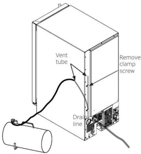
- Remove the top clamp from the vent tube, for easy access to the air hose.
- Apply air pressure (approximately 10 psi) to the end of he vent tube which will purge the remainder of the water from the drain pump and the drain line.
- Reinstall the vent tube and clamp to the back of the ice machine and remove the winterization plug from the ice bin and save it for future use.
Drain Pump Removal
- Unplug the ice machine from the electrical supply and remove the rear access cover from the ice machine.
- Remove the front panel and the toe grille from the front of the ice machine.
- Remove the front and rear drain pump brackets.
- Unscrew the 3 hose clamps and remove the 3 hoses from the front of the drain pump.
- Unscrew the leveling leg in the back corner until the end of the threaded portion is flush with the threaded nut insert in the base.
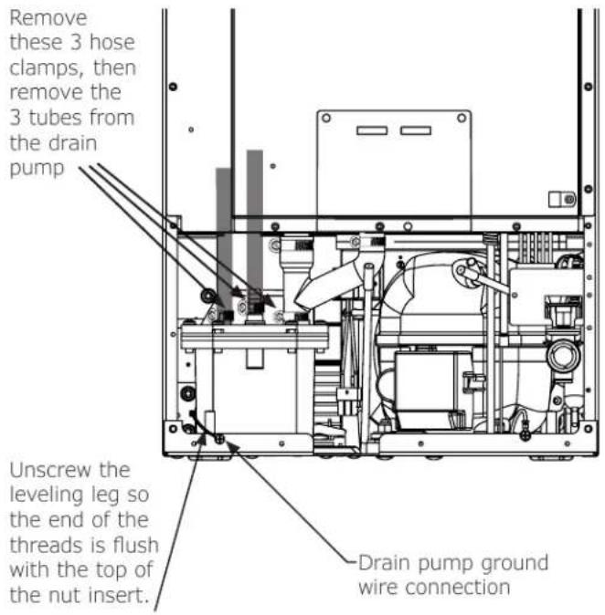
To Restart the Ice Machine
- Reconnect or turn on the water supply line.
- Reconnect drain tubing if removed.
- Plug in the power cord to a wall outlet and turn the ice machine on.
- Check the water inlet, drain lines, and fittings for any water leaks.
- Check drain pump (if equipped) operation by pouring approximately two (2) quarts of water into the ice storage bin. The drain pump should activate and discharge water. Check for water leaks at all hose connections.
Troubleshooting
BEFORE CALLING FOR SERVICE

WARNING
ELECTROCUTION HAZARD
- Never attempt to repair or perform maintenance on the appliance until the main electrical power has been disconnected. Turning the appliance control "OFF" does not remove electrical power from the unit's wiring.
- Replace all parts and panels before operating.
If the appliance appears to be malfunctioning, read through this manual first. If the problem persists, check the troubleshooting guide below. Locate the problem in the guide and refer to the cause and its remedy before calling for service. The problem may be something very simple that can be solved without a service call. However, it may be required to contact your dealer or a qualified service technician.
Ice machine does not operate:
- Is the ice machine's power cord plugged in?
Plug the power cord into a grounded 3 prong outlet. - Is the electronic control showing the "ICE" position?
Check the control to be sure it is in the "ICE" position
• Is a fuse blown or a circuit breaker been tripped?
Replace a blown fuse or reset a tripped circuit breaker.
- Is the temperature of the room cooler than it normally is?
The minimum room temperature is 55^ F ( 13^ C). The bin thermistor may be sensing the room temperature and shut off before the bin is full of ice. If the room temperature remains low the ice machine may not restart.
• Is there a drain pump in the ice machine?
The drain pump is designed to temporarily shut the unit off when large quantities of water create a high-limit condition. Wait a few minutes as the drain pump will continue to operate to dispose of the excess water. If there is still water in the ice bin check the drain pump vent line and drain line for obstructions or kinking.
The ice machine is noisy:
Many sounds of an ice machine are different than your household refrigerator. This subject is discussed on page 11, but check the following:
- Do you hear water being circulated in the ice machine?
This is a normal sound as water is added once every ice making cycle.
• Is there a "whooshing" sound?
Make sure water is getting to the ice machine. Also check to make sure the drain plug is fully seated in the water reservoir.
- Is there an ice slab caught between the evaporator plate and the grid cutter?
First check to see if the ice machine is level. If the ice machine is level run a cleaning cycle.
ICE PRODUCTION
Little or no ice production from the ice machine:
• Is the electronic control set to the "ICE" position?
Check the control to be sure it is in the "ICE" position
• Is water getting to the ice machine?
Make sure nothing is restricting the water supply such as a closed water valve or a blown fuse or tripped circuit breaker, or a kinked supply line, or low water pressure.
• Has the ice machine just been started?
A typical ice production cycle can take up to 112 hours. Initial start up cycles can take longer. Check the ice machine after 24 hours for ice accumulation in the bin.
• Is the reservoir drain plug in place?
Check that the reservoir drain plug is properly seated.
• Is the water distributor tube restricted?
Run a cleaning cycle to clean the ice machine. Also check any filters to make sure they are not restricted.
• Is the condenser fan air flow restricted?
Make sure the grille in the front of the ice machine is open for proper air circulation.
• Is the room and/or water temperature to warm?
Move the ice machine to an area where the ambient temperature is below 90^ F ( 32^ C) for built-in ice machines or below 100^ F ( 38^ C) for freestanding ice machines. The ice machine should not be placed next to a heat source such as an oven. Check the cold water connection.
• Is there scale build up in the ice machine?
If there is scale build up on the evaporator, the ice machine needs to be cleaned. See "Cleaning the Ice machine".
ICE QUALITY
Odor, grey color, or off taste in the ice:
- Is there mineral scale build up on the evaporator plate?
The ice machine needs cleaning. See "Cleaning the Ice Machine".
• Is there a high mineral content in the water?
The water may need to be filtered.
• Are food items being stored in the ice bin?
Remove food from the ice bin.
- Unpleasant Odors may require the use of a charcoal filter on the water supply line.
Clumps of ice:
• Are there clumps of ice in the bin?
If the ice isn't used on a regular basis it will melt and form into clumps. Break up the ice clumps with the ice scoop.
Ice cubes are too big or too small:
• Is there low ice consumption?
Ice is slowly melting in the ice bin which will affect the size of the cubes. This is normal. When the ice bin needs to be replenished, cubes will return to the regular size.
• Is the ice slab releasing?
Clean the evaporator. See "Cleaning the Ice Machine"
• Is the distributor tube restricted?
Check the water line to the ice machine to make sure there are no restrictions or kinks in the line. Check all filters to make sure they are not restricted. Check that the water flows evenly out of the distributor tube, if not, clean the ice machine. See "Cleaning the Ice Machine".
PLUMBING PROBLEMS
• Is the drain hose aligned over the drain?
Move the ice machine to align the drain.
• Is the ice machine draining properly?
Check that there are no kinks or restrictions in the drain lines; this can cause water to back up in the ice bin.
Check that foreign material is not blocking the ice bin drain located at the right rear corner of the ice bin. Check the drain pump discharge and vent line or any restrictions or kinks. Check that the drain pump is level.
NOTE:
If there are plumbing issues outside of the ice machine, they cannot be repaired by the service technician. A qualified plumber will have to be called.
If the drain pump reservoir (not the ice machine bin) reaches overfill condition, the power to the ice machine will be shut off.
If the ice machine is not working, check the following:
• Make sure there is power at the receptacle.
• Make sure the ice machine is turned on.
• Make sure the ice bin is not full.
Then check the drain pump:
The pump does not run:
• Make sure the pump is plugged in and there is power to the receptacle.
- Check the inlet to the drain pump for debris and clean as needed. Remove clamps and inlet tube from drain pump to check for and remove debris.
• Make certain the vent line is free of kinks/sharp bends or restrictions.
- Make certain there is enough water to activate the drain pump. It will take at least one (1) quart (.95 liters) of water to activate the drain pump.
The pump runs, but no water is pumped out:
- Check that the vent is clear and free of restrictions.
- Check the discharge line to make certain there are no restrictions.
- Make sure that the discharge tubing has not exceeded the maximum lift of eight (8) feet (2.44 meters) and the horizontal run is not greater than twenty (20) feet (6.1 meters).
The pump runs and then quickly turns off repeatedly:
- Check to make certain the drain pump is level.
- Check that the vent is clear and free of restrictions.
The ice machine is running but not producing ice:
- Check to make sure water is not backing up in the ice bin.
Wire Diagram
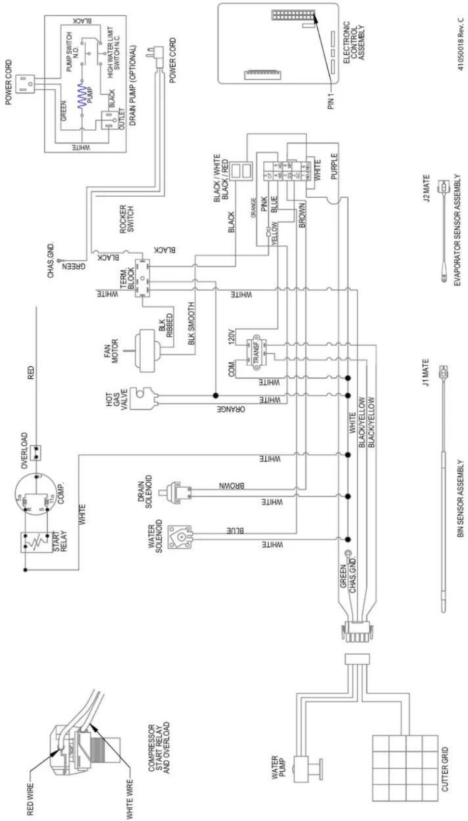
flowchart
graph TD
    A["RED WIRE"] --> B["START RELAY"]
    C["WHITE WIRE"] --> D["COMP."]
    B --> E["OVERLOAD"]
    D --> E
    E --> F["RED"]
    G["COMPRESSOR START RELAY AND OVERLOAD"] --> H["WHITE"]
    I["WATER PUMP"] --> J["GREEN CHAS.GND."]
    K["CUTTER GRID"] --> L["BIN SENSOR ASSEMBLY"]
    M["J1 MATE"] --> N["BLACK/YELLOW"]
    O["J2 MATE"] --> P["EVAPORATOR SENSOR ASSEMBLY"]
    Q["PIN 1"] --> R["ELECTRONIC CONTROL ASSEMBLY"]
    S["POWER CORD"] --> T["DRAIN PUMP (OPTIONAL)"]
    U["CHAS.GND."] --> V["FAN MOTOR"]
    W["BRID RED"] --> X["BLK RIBBED"]
    Y["Black"] --> Z["ROCKER SWITCH"]
    AA["ORANGE"] --> AB["COM. 120V"]
    AC["TRANSF"] --> AD["WHITE"]
    AE["WHITE"] --> AF["ORANGE"]
    AG["BROWN"] --> AH["WHITE"]
    AI["PURPLE"] --> AJ["WHITE"]
    AK["PINK"] --> AL["BLACK / WHITE BLACK / RED"]
    AM["BLEW"] --> AN["GREEN"]
    AO["HOLD"] --> AP["OUTLET"]
    AQ["MINI"] --> AR["MINI"]
    AS["MINI"] --> AT["MINI"]
    AU["MINI"] --> AV["MINI"]
Product Liability
Field service technicians are authorized to make an initial assessment in the event of reported damages. If there are any questions about the process involved, the technician should call the manufacturer for further explanation.
While inspecting for defects or installation issues, photos should be taken to document any damages or issues found.
During the assessment, if the service technician is able to find the source of the damage and it can be resolved by replacement of a part, the servicer is authorized to replace the part in question. The part that caused the damage must be returned to the manufacturer in its entirety. The part must be clearly labeled with the serial number of the unit it was removed from, the date, and the servicer who removed the part.
If the service technician determines the damage is the result of installation issues (water connection/drain, etc.), the consumer would be notified and the issues shall be resolved at the direction of the consumer.
If damage is evident and the service technician is unable to find the source, the manufacturer must be contacted at +1.616.754.5601 for further direction.
1260 Van Deinse St. Greenville, MI
T: +1.616.754.5601
Website: vikingrange.com/commercial
R-600A Specifications
For R-600a refrigerant service tips and more videos, go to: www.u-line.com/videos.
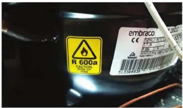
Flammability warnings for a pure-iso-butane refrigerant.
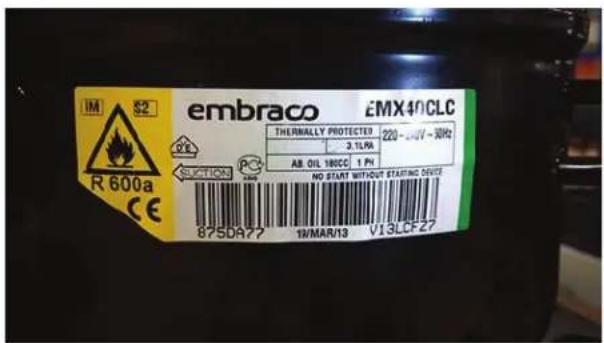
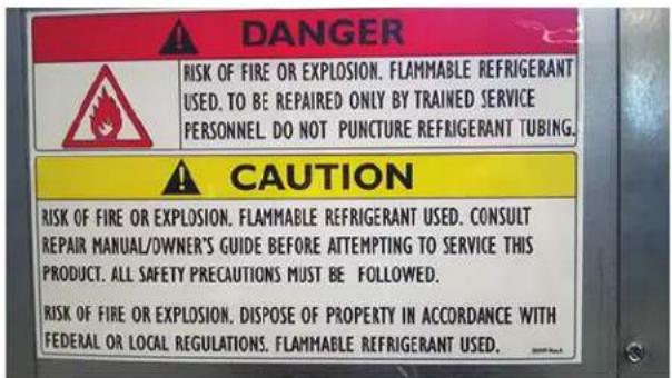
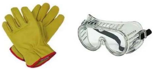
Gloves and Eye Protection must be used.
natural_image
Two yellow protective gloves and a clear safety goggles (no text or symbols visible)R-600a is considered non-toxic, but is flammable when mixed with air.
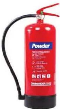
Keep a dry powder type fire extinguisher in the work area.
natural_image
Red fire extinguisher with black hose and safety labels (no readable text on body)R-600a is heavier than air, do not allow any leakage/migration to low areas such as basements and stairs.
Never use a torch on a fully charged refrigeration system.
Never substitute U-Line OEM replacement parts or methods of construction.
R-600a must be stored and transported in approved containers.
WARNING
Only skilled and well trained service technicians permitted to service R-600a equipped products.
All tools and equipment must be approved for use with R-600a refrigerant.
Local, state and federal laws, standards must be observed along with proper certification and licensing.
Ventilation is required during servicing.
No conversions to R-600a from any other refrigerants. OEM R-600a equipped unit only.
Service area must be free of ignition sources.
No smoking is allowed in the service area.
All replacement electrical components must be OEM and installed properly (sealed and covered).
If the evaporator is cold prior to service, it must be thawed prior to service.
When using a vacuum pump, start pump before opening refrigeration system.
Vacuum pump and recovery equipment should be at least 10 feet from the work area.
It is recommended that a simple LPG gas detector is on site during service.
Ensure that all R-600a is removed from the system prior to brazing any part of the sealed system.
Only a clean, dry leak free system should be charged with R-600a.
R-600A SPECIFICATIONS/LABELING
R-600a equipped products are labeled (both the unit and the compressor).
R-600a is colorless and odorless.
R-600a is considered non-toxic, but is flammable when mixed with air.
Do not remove or alter any R-600a labeling on the product.
Use only a refrigerant grade R-600a from a properly labeled container.
RECOVERING/RECLAIMING R-600A
(R-600a has been exempted from recovery/reclaiming requirements by the US EPA)
Recovery/Reclaiming equipment must be approved for use with R-600a.
Ensure the evaporator is at room temperature prior to recovery/reclaiming R-600a.
Use a common piercing pliers or piercing valve to remove R-600a from the compressor process tube. (Note: Piercing devices must not be left on the system and must be replaced with a Schrader type valve.)
Evacuate/reclaim via the piecing pliers to ensure the system is empty of R-600a before any system work is performed.
The recovery cylinder must be evacuated (no air inside) prior to accepting R-600a.
The recovery cylinder must not be filled more than 45% safe fill level and refrigerants must not be mixed.
The recovery cylinder must be clearly marked with R-600a and Flammable Warning labels.
Ensure proper ventilation during recovery/reclaiming of R-600a.
Start vacuum pump/recovery pump prior to piercing the compressor process tube.
Follow recovery/reclaim OEM instructions for the specific equipment used.
SYSTEM REPAIR
Ensure no residual R-600a refrigerant is left within the system prior to repair (simple venting is not sufficient).
Evacuate and charge with dry nitrogen for leak checks.
Repair leaks or replace system parts as required.
When re-brazing, the system must be purged with dry nitrogen and at least one access point open to the atmosphere.
When re-brazing, proper ventilation is required along with constant monitoring for the presence of R600a refrigerant.
The filter dryer must be replaced any time the sealed system is serviced.
No system should be open to the atmosphere for longer than 15 minutes to avoid moisture migration into the system components.
LEAK DETECTION
After removal of the R-600a, the unit can be charged with dry nitrogen or helium.
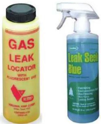
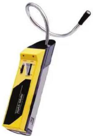
Electronic leak detection or soap solution can be used to check for nitrogen/helium leaks.
natural_image
Yellow and black handheld device with coiled cable, no visible text or symbolsNever use a halide torch or lighted match to check the system for leaks at any time.
The high side of the refrigeration system (compressor discharge to outlet of drier) must be leak tested with the compressor running.
The low side of the refrigeration system (evaporator, compressor and suction line) must be leak tested with the compressor off (equalized pressure).
RECHARGING
No air is ever to be allowed inside the refrigeration system (R-600a refrigerant or dry nitrogen only).
Never use a torch on a fully charged refrigeration system.
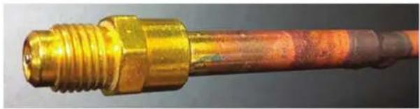
Install a Schrader Type access port on the compressor process stub.
natural_image
Close-up of a metallic heating element with threaded shaft and copper end (no text or symbols visible)Evacuate the system to 100 microns prior to charging.
Weigh in the R-600a charge using a refrigerant scale. (run compressor an extra two minutes to clear the charging hoses).
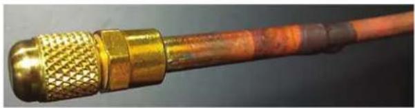
Seal the Schrader Type access port, a proper cap and seal must be used to close the system.
natural_image
Close-up of a metallic coaxial connector with threaded ends and copper-colored insulation (no text or symbols visible)SUMMARY
Safely handling R-600a requires proper procedures and training.
R-600a approved service tools must be used.
R-600a labeling must not be removed or altered.
Proper ventilation during service is required.
Never apply a torch to a charged R-600a refrigeration system.
Use OEM replacement service parts and do not alter the construction of the unit.
System Diagnosis Guide
| System Condition | Suction Pressure | Suction Line | Compressor Discharge | Condenser | Capillary Tube | Evaporator | Wattage |
| Normal | Normal | Slightly below room temperature | Very hot | Very hot | Warm | Cold | Normal |
| Overcharge | Higher than normal | Very cold may frost heavily | Slightly warm to hot | Hot to warm | Cool | Cold | Higher than normal |
| Undercharge | Lower than normal | Warm- near room temperature | Hot | Warm | Warm | Extremely cold near inlet - Outlet below room temperature | Lower than normal |
| Partial Restriction | Somewhat lower than normal vacuum | Warm- near room temperature | Very hot | Top passes warm - Lower passes cool (near room temperature) due to liquid | Room temperature (cool) or colder | Extremely cold near inlet - Outlet below room temperature backing up | Lower than normal |
| Complete Restriction | In deep vacuum | Room temperature (cool) | Room temperature (cool) | Room temperature (cool) | Room temperature (cool) | No refrigeration | Lower than normal |
| No Gas | 0 PSIG to 25" | Room temperature (cool) | Cool to hot | Room temperature (cool) | Room temperature (cool) | No refrigeration | Lower than normal |
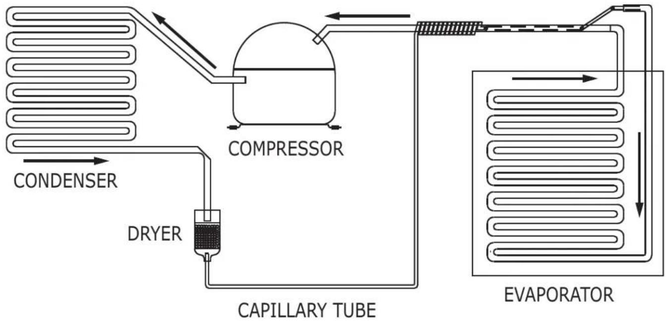
flowchart
graph LR
    A["CONDENSER"] --> B["DRYER"]
    B --> C["CAPILLARY TUBE"]
    C --> D["COMPRESSOR"]
    D --> E["EVAPORATOR"]
    E --> F["Return Line"]
Compressor Specifications

DANGER
Electrocution can cause death or serious injury. Burns from hot or cold surfaces can cause serious injury. Take precautions when servicing this unit.
Disconnect the power source.
Do not stand in standing water when working around electrical appliances.
Make sure the surfaces you touch are not hot or frozen.
Do not touch a bare circuit board unless you are wearing an anti-static wrist strap that is grounded to an electrical ground or grounded water pipe.
Handle circuit boards carefully and avoid touching components.
| FMXA9C | |
| REFRIGERANT | R600A |
| VOLTAGE | 115 VAC |
| FREQUENCY | 60 Hz |
| START WINDING | 5 Ohm at 77o F |
| RUN WINDING | 7 Ohm at 77o F |
| RUN TO START | 12 Ohm at 77o F |
| LRA | 8.0 A |
| FLA | 2.18 A |
| STARTING DEVICE | Run Cap 12VF 250V P2 |
*All resistance readings are ± 10%
Control Operation-Service
UI BUTTON LAYOUT
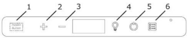
1. Hidden Button
- Access Service Menu
• No LED directly above. All LED's turn on with button
2. Up Button
• Increases temperature
• Navigates through service menu
3. Down Button
• Decreases temperature
• Navigates through service menu
4. Light Button
• Activates light for 3 hours on select models
• Used to select items in service menu
5. Power Button
- Turns unit on/off
6. Clean Button
- Activates Clean Cycle
CONTROL FUNCTION GUIDE
| FUNCTION | COMMAND | DISPLAY/OPTIONS |
| ON/OFF | Press 🎨 and release | Unit will immediately turn ON or OFF |
| Clean Mode | See “Cleaning” section | |
| Sabbath Mode | See “Sabbath Mode” section |
Showroom Mode
This mode is designed to show units in a display environment. When in this mode the only functions will be the control and cabinet lights. The compressor, fans, etc. will not operate. To enter/exit this mode hold the light key and the power key for 5 seconds. The display will flash once and beep and the degree symbol will begin to flash. When the degree symbol is flashing the unit will allow the use of the control for demonstrations. The unit can be left in this mode indefinitely.
Service Mode
This mode has options available for service diagnostics. To enter the mode hold the hidden key for 10 seconds. The display will show "O." When in this mode use the up and down arrows to select the desired option. The LIGHT key is the ENTER key and will initiate the function. If changing a setting, you must press the LIGHT key again to retain the changed setting. To exit the service mode scroll to option "O" and press the LIGHT key. After five minutes of not touching any keys the mode will also exit automatically.
SERVICE MODE GUIDE
(For adjustments, see Service Mode Guide)
-
Exit
-
Thermistor 1 temperature not including offsets.
- Thermistor 2 temperature not including offsets.
- Thermistor 3 temperature not including offsets.
-
Thermistor 4 temperature not including offsets.
-
Thermistor 1 offset. (+/- 10)
-
Thermistor 2 offset. (+/- 10)
-
Thermistor 3 offset. (+/- 10)
-
Thermistor 4 offset. (+/- 10)
-
Thermistor 2 set point
-
Thermistor 3 set point.
-
Thermistor 4 set point.
-
Defrost Interval (0 to 99 hr)
-
Defrost duration (0 to 99 min)
-
Error Log (See Appendix)
-
Clear error log (hold light key until cleared)
-
Thermistor 1 differential (+5)
-
Thermistor 3 differential (+5)
-
Evaporator fan on delay (0 to 99 sec)
-
Evaporator fan off delay (0 to 99 sec)
-
Individual component toggle
-
Option #0 - Exit
- Option #1 - Relay 1
- Option #2 - Relay 2
- Option #3 - Relay 3
- Option #4 - Relay 4
- Option #5 - Relay 5
- Option #6 - Relay 6
- Option #7 - DC Output 1
- Option #8 - DC Output 2
- Option #9 - DC Output 3
- Option #10 - DC Output 4
- Option #11 - DC Output 5
- Option #12 - Serial output (Compressor)
-
Model number
-
Light All Segments
-
Activate Defrost/Harvest- press and hold for 3 seconds to activate defrost/harvest
-
Defaults- press and hold for 3 seconds to restore all values to factory defaults.
-
Main Software (Display only)
-
Live Log Period (frequency that data is output to diagnostics port)
-
Factory test mode (0=Off, 1=On)
-
Compressor RPM
-
Freeze time adjust (Model 54 only)
-
Harvest time adjust (Model 54 only)
-
Low temp alarm limit (Model 55 only)
-
High temp alarm limit (Model 55 only)
APPENDIX
SERVICE MODE GUIDE
1. THERMISTOR 1
This shows the pure thermistor reading with no offsets taken into account.
2. THERMISTOR 2
This shows the pure thermistor reading with no offsets taken into account.
-
Does not apply to this model.
-
Does not apply to this model.
5. THERMISTOR 1 OFFSET
(DO NOT MAKE AN ADJUSTMENT TO THIS WITHOUT CONTACTING TECH LINE: +1 414.354.0300) This calibration is only to be used if actual temperature at thermistor #1 is off from set point. By adjusting the offset higher we can force the unit to drive the temperature down below the set point. (example: adjusting from 0 to +2 will drop the unit temperature 2 degrees)
6. THERMISTOR 2 OFFSET
(DO NOT MAKE AN ADJUSTMENT TO THIS WITHOUT CONTACTING TECH LINE: +1 414.354.0300)
-
Does not apply to this model.
-
Does not apply to this model.
-
Does not apply to this model. This shows the thermistor reading with offsets taken into account.
-
Does not apply to this model.
-
Does not apply to this model.
-
Does not apply to this model.
-
Does not apply to this model.
14. VIEW ERROR LOG
A list of errors in the order they occurred will scroll on the display. All errors are logged in memory. Only door error is displayed on the display and has an audible signal.
E0: Door 1 open.
E1: Thermistor 1 open.
E2: Thermistor 2 open.
E3: Does not apply to this model.
E4: Does not apply to this model.
E5: Thermistor 1 shorted.
E6: Thermistor 2 shorted.
E7: Does not apply to this model.
E8: Does not apply to this model.
E9: Door open.
E10: Door 2 open.
E11 - E13 Do not apply to this model.
P1: Pump Circuit open (Only if unit has drain pump.)
15: CLEAR ERROR LOG
To clear errors, press and hold (5 seconds) when CLR is flashing.
16: THERMISTOR - 1 DIFFERENTIAL
This number should not be adjusted.
-
Does not apply to this model.
-
THIS NUMBER SHOULD NOT BE ADJUSTED
-
THIS NUMBER SHOULD NOT BE ADJUSTED
-
INDIVIDUAL COMPONENT TOGGLE SEE RELAY / OUTPUT CHART
-
MODEL NUMBER INDICATOR
Displays the two-digit model number of the specific unit. See Model list table.
- LIGHT ALL LED SEGMENTS
This will illuminate all the LEDs on the display to ensure they work properly
- ACTIVATE DEFROST /HARVEST
-Press and hold for 3 seconds to activate
- FACTORY DEFAULTS
-Press and hold for 3 seconds to restore all values to factory defaults
-
MAIN SOFTWARE
-
Does not apply to this model
-
FACTORY TEST MODEL - DO NOT USE
-
COMPRESSOR RPM
-
-
- Do not apply to this model.
-
PROGRAM MODEL NUMBER
| Model # | |
| 82 | VCCC115-SS81A- CRAFT ICE |
PROGRAMMING THE UNIT TO CORRECT MODEL NUMBER
-
Disconnect the unit from power source.
-
Push and hold the U-Line button.
-
While still holding the U-Line button, plug the unit into the appropriate power source.
-
When the flashing digits appear (3-5 seconds), use the up and down arrow buttons to select the appropriate model number from the chart below. or
-
Press the light bulb button once.
-
The display will blink, and then will appear as the programmed display.
| Display # | Relay / Output |
| Option #0 | Exit |
| Option #1 | Relay 1 |
| Option #2 | Relay 2 |
| Option #3 | Relay 3 |
| Option #4 | Relay 4 |
| Option #5 | Relay 5 |
| Option #6 | Relay 6 |
| Option #7 | DC Output 1 |
| Option #8 | DC Output 2 |
| Option #9 | DC Output 3 |
| Option #10 | DC Output 4 |
| Option #11 | DC Output 5 |
| Option #12 | Serial output (Compressor) |
Relay / Output Chart
| Relay 1 | Compressor |
| Relay 2 | - |
| Relay 3 | Circulation Pump |
| Relay 4 | Water Inlet |
| Relay 5 | Hot Gas Valve |
| Relay 6 | Cond Fan |
| DC1 | Light 1 |
| DC2 | Light 2 |
| DC3 | - |
| DC4 | - |
| DC5 | Cond Fan |
Thermistor
Thermistors are used for various temperature readings. Thermistors provide reliable temperature readings using a resistance which varies based on surrounding temperatures. If a faulty thermistor is suspected, it may be tested using an accurate ohmmeter.
Thermistor connections must be kept clean. A thermistor connection that has become corroded can cause resistance values from the thermistor to change as they pass through a dirty connection to the board.
It is for that reason that we apply dielectric grease to all of our thermistor connections. Dielectric grease will help to keep thermistor connections clean and dry.
If you change a thermistor in the unit, please re-apply dielectric grease to the connection. If you encounter a dirty thermistor connection, you should replace the thermistor and the thermistor harness.
This unit has one thermistor located along the right hand sidewall of the ice bin. It is used to maintain the ice level in the bin.
Thermistor Resistance Data
| Temp (F) | Temp (C) | Nominal Resistance (OHMS)* |
| -40 | -40 | 169157 |
| -31 | -35 | 121795 |
| -22 | -30 | 88766 |
| -13 | -25 | 65333 |
| -4 | -20 | 48614 |
| 5 | -15 | 36503 |
| 14 | -10 | 27681 |
| 23 | -5 | 2116 |
| 32 | 0 | 16330 |
| 41 | 5 | 12696 |
| 50 | 10 | 9951 |
| 59 | 15 | 7855 |
| 68 | 20 | 6246 |
| 77 | 25 | 5000 |
| 86 | 30 | 4029 |
| 95 | 35 | 3266 |
| 104 | 40 | 2665 |
| 113 | 45 | 2186 |
| 122 | 50 | 1803 |
| 131 | 55 | 1495 |
| 140 | 60 | 1247 |
| 149 | 65 | 1044 |
| 158 | 70 | 879 |
| 167 | 75 | 743 |
| 176 | 80 | 631 |
* (+/- 5%)
U-Line Corporation (U-Line) Limited Warranty
One Year Limited Warranty
For one year from the date of original purchase, this warranty covers all parts and labor to repair or replace any part of the product that proves to be defective in materials or workmanship. For products installed and used for normal residential use, material cosmetic defects are included in this warranty, with coverage limited to 60 days from the date of original purchase. All service provided by U-Line under the above warranty must be performed by a U-Line factory authorized servicer, unless otherwise specified by U-Line. Service provided during normal business hours.
Two Year Limited Warranty (5 Class Product)
For two years from the date of original purchase, this warranty covers all parts and labor to repair or replace any part of the product that proves to be defective in materials or workmanship. For products installed and used for normal residential use, material cosmetic defects are included in this warranty, with coverage limited to 60 days from the date of original purchase. All service provided by U-Line under the above warranty must be performed by a U-Line factory authorized servicer, unless otherwise specified by U-Line. Service provided during normal business hours.
Available Second & Third Year Limited Warranty
In addition to the standard one and two year warranties outlined above, U-Line offers a one year extension of the warranties from the date of purchase, free of charge. To take advantage of this extension, you must register your product with U-Line within 60 days from the date of purchase at u-line.com and provide proof of purchase. Nugget Ice Machine proof of purchase must include the purchase of an in-line water filter and filter head to qualify for this additional limited warranty.
Five Year Sealed System Limited Warranty
For five years from the date of original purchase, U-Line will repair or replace the following parts, labor not included, that prove to be defective in materials or workmanship: compressor, condenser, evaporator, drier, and all connecting tubing. All service provided by U-Line under the above warranty must be performed by a U-Line factory authorized servicer, unless otherwise specified by U-Line. Service provided during normal business hours.
Terms
These warranties apply only to products installed in any one of the fifty states of the United States, the District of Columbia, or the ten provinces of Canada. The warranties do not cover any parts or labor to correct any defect caused by negligence, accident or improper use, maintenance, installation, service, repair, acts of God, fire, flood or other natural disasters. The product must be installed, operated, and maintained in accordance with your product's User Guide.
The remedies described above for each warranty are the only ones that U-Line will provide, either under these warranties or under any warranty arising by operation of law. U-Line will not be responsible for any consequential or incidental damages arising from the breach of these warranties or any other warranty, whether express, implied, or statutory. Some states do not allow the exclusion or limitation of incidental or consequential damages, so the above limitation or exclusion may not apply to you. These warranties give you specific legal rights, and you may also have other rights which vary from state to state.
Any warranty that may be implied in connection with your purchase or use of the product, including any warranty of merchantability or any warranty fit for a particular purpose is limited to the duration of these warranties, and only extends to five years in duration for the parts described in the section related to the five year limited warranty above. Some states do not allow limitations on how long an implied warranty lasts, so the above limitations may not apply to you.
• The warranties only apply to the original purchaser and are non-transferable.
• The second, third, and five year warranties cover products installed and used for normal residential or designated marine use only.
• The warranties apply to units operated outside only if designed for outdoor use by model and serial number.
- U-Line Commercial products are covered by the one year and 5 year limited warranties and are not eligible for the second and third year limited warranties.
• Replacement water filters, light bulbs, and other consumable parts are not covered by these warranties.
- The start of U-Line's obligation is limited to four years after the shipment date from U-Line.
• In-home instruction on how to use your product is not covered by these warranties.
• Food, beverage, and medicine loss are not covered by these warranties.
- If the product is located in an area where U-Line factory authorized service is not available, you may be responsible for a trip charge or you may be required to bring the product to a U-Line factory authorized service location at your own cost and expense.
- Units purchased after use as floor displays, and/or certified reconditioned units, are covered by the limited one year warranty only and no coverage is provided for cosmetic defects.
• Signal issues related to Wi-Fi connectivity are not covered by these warranties.
For parts and service assistance, or to find U-Line factory authorized service near you, contact U-Line: 8900 N. 55^th Street, Milwaukee, WI 53223 • u-line.com • onlineservice@u-line.com • +1.414.354.0300
Copyright U-Line Corporation. All Rights Reserved. | Publication Number 30379 | 11/2022 Rev. P
- USER GUIDE & SERVICE MANUAL
- Click on any section below to jump directly there
- Maintenance
- Operating Instructions
- Service
- WELCOME TO U-LINE
- U-LINE — RIGHT PRODUCT. RIGHT PLACE. RIGHT TEMPERATURE.®
- PRODUCT INFORMATION
- PROPERTY DAMAGE / INJURY CONCERNS
- GENERAL INQUIRIES
- CONNECT WITH US
- SERVICE & PARTS ASSISTANCE
- Safety and Warning
- NOTICE
- SAFETY ALERT DEFINITIONS
- DANGER
- WARNING
- CAUTION
- CALIFORNIA PROPOSITION 65
- Disposal and Recycling
- Environmental Requirements
- Electrical
- Cutout & Product Dimensions
- PREPARE SITE
- Side-by-Side Installation
- OTHER SITE REQUIREMENTS
- Hinge-by-Hinge Installation (Mullion)
- Water Hookup
- WATER SUPPLY
- NOTE:
- Drain
- DRAIN CONNECTION
- General Installation
- LEVELING INFORMATION
- INSTALLATION TIP
- INSTALLATION
- Grille Installation
- REMOVING AND INSTALLING GRILLE
- Removing the grille
- Installing the grille
- Door Swing
- Door Adjustments
- DOOR ALIGNMENT AND ADJUSTMENT
- Alignment and Adjustment Procedure
- REVERSING THE DOOR
- Reposition Magnet
- First Use
- Control Operation
- Control Function Guide
- Door Alert Notification
- BrightShield™
- ICE
- ICE PRODUCTION
- NEW SOUNDS
- Cleaning
- Clean mode:
- To Clean Your Ice Machine:
- CABINET
- EXTERIOR
- INTERIOR
- Cleaning Condenser
- INTERVAL - EVERY SIX MONTHS
- Extended Non-Use
- CLEAN THE ICE MACHINE
- WINTERIZATION
- Drain Pump Removal
- To Restart the Ice Machine
- Troubleshooting
- BEFORE CALLING FOR SERVICE
- ELECTROCUTION HAZARD
- Ice machine does not operate:
- The ice machine is noisy:
- Little or no ice production from the ice machine:
- ICE QUALITY
- Odor, grey color, or off taste in the ice:
- Clumps of ice:
- Ice cubes are too big or too small:
- PLUMBING PROBLEMS
- If the ice machine is not working, check the following:
- Then check the drain pump:
- The pump does not run:
- The pump runs, but no water is pumped out:
- The pump runs and then quickly turns off repeatedly:
- The ice machine is running but not producing ice:
- Product Liability
- R-600A Specifications
- R-600A SPECIFICATIONS/LABELING
- RECOVERING/RECLAIMING R-600A
- SYSTEM REPAIR
- LEAK DETECTION
- RECHARGING
- SUMMARY
- System Diagnosis Guide
- Compressor Specifications
- Control Operation-Service
- Hidden Button
- Up Button
- Down Button
- Light Button
- Power Button
- Clean Button
- Showroom Mode
- Service Mode
- SERVICE MODE GUIDE
- APPENDIX
- THERMISTOR 1
- THERMISTOR 2
- THERMISTOR 1 OFFSET
- THERMISTOR 2 OFFSET
- VIEW ERROR LOG
- 15: CLEAR ERROR LOG
- 16: THERMISTOR - 1 DIFFERENTIAL
- PROGRAMMING THE UNIT TO CORRECT MODEL NUMBER
- Thermistor
- U-Line Corporation (U-Line) Limited Warranty
- One Year Limited Warranty
- Two Year Limited Warranty (5 Class Product)
- Available Second & Third Year Limited Warranty
- Five Year Sealed System Limited Warranty
- Terms
Brand : U-Line
Model : URCC115-SS81A
Category : Ice Maker