3018CLRINT-00C - Ice Maker U-Line - Free user manual and instructions
Find the device manual for free 3018CLRINT-00C U-Line in PDF.


| Product Type | Ice Maker |
| Brand | U-Line |
| Model | 3018CLRINT-00C |
| Installation Type | Built-in or Freestanding |
| Width | 15 inches (38.1 cm) |
| Height | 34 inches (86.4 cm) |
| Depth | 23 inches (58.4 cm) |
| Ice Production | Up to 25 lbs (11.3 kg) per day |
| Ice Storage Capacity | 15 lbs (6.8 kg) |
| Ice Type | Clear cube ice |
| Power Supply | 115V / 60Hz |
| Amperage | 1.5 A |
| Energy Consumption | ~140 kWh/year |
| Control Type | Electronic touchpad |
| Door Finish | Stainless steel |
| Water Filtration | Optional external filter kit |
| Self-Cleaning Function | Yes, with integrated cleaning cycle |
| Condenser Type | Air-cooled |
| Refrigerant | R-134a |
| Annual Energy Use | 140 kWh |
| Weight | Approximately 75 lbs (34 kg) |
| Noise Level | ~45 dBA |
| Defrost Method | Automatic |
| Warranty | 2 years parts and labor, 5 years sealed system |
Frequently Asked Questions - 3018CLRINT-00C U-Line
User questions about 3018CLRINT-00C U-Line
0 question about this device. Answer the ones you know or ask your own.
Ask a new question about this device
Download the instructions for your Ice Maker in PDF format for free! Find your manual 3018CLRINT-00C - U-Line and take your electronic device back in hand. On this page are published all the documents necessary for the use of your device. 3018CLRINT-00C by U-Line.
USER MANUAL 3018CLRINT-00C U-Line
USER GUIDE & SERVICE MANUAL

natural_image
Top-down view of a wine bottle, fresh carrots, parsley, and ice cream on a dark wooden surface (no text or symbols visible on main objects)3000 Series • 3018CLR • 18" Clear Ice Machine (115V)
Tip: Click on any section below to jump directly there
Table of Contents
Intro
Wire Diagram
Warranty
Safety
Safety and Warning
Disposal And Recycling
Installation
Environmental Requirements
Electrical
Cutout & Product Dimensions
Side by Side Installation
Water Hookup
Drain
Drain Pump
General Installation
Grille Installation
Door Swing
Door Adjust
Maintenance
Cleaning
Cleaning Condenser
Extended Non-Use
Operating Instructions
First Use
Control Operation
Ice
Airflow and Product Loading
Service
WELCOME TO U-LINE
Congratulations on your U-Line purchase. Your product comes from a company with over five decades of premium modular ice making, refrigeration, and wine preservation experience. U-Line creates products focused on functionality, style, and inspired innovations — paying close attention to even the smallest details. Applications include residential, outdoor, ADA height compliant, marine, and commercial. Complete product categories include Beverage Centers, Wine Refrigerators, Ice Machines, Refrigerators, Freezers, and Dispensers.
Our advanced refrigeration systems, large and flexible capacities, and Built-In to Stand Out ^® clean integrated look allow you to preserve the right product, in the right place, at the right temperature. Since 2014, U-Line has been part of the Middleby family of brands. All products are designed, engineered, and assembled in Milwaukee, Wisconsin, USA, and select products are available worldwide.
PRODUCT INFORMATION
Looking for additional information on your product? User Guides, Spec Sheets, CAD Drawings, Compliance Documentation, and Product Warranty information are all available for reference and download at u-line.com.
PROPERTY DAMAGE / INJURY CONCERNS
In the unlikely event property damage or personal injury is suspected related to a U-Line product, please take the following steps:
- U-Line Customer Care must be contacted immediately at +1.414.354.0300.
- Service or repairs performed on the unit without prior written approval from U-Line is not permitted. If the unit has been altered or repaired in the field without prior written approval from U-Line, claims will not be eligible.
GENERAL INQUIRIES
U-Line Corporation
8900 N. 55th Street
Milwaukee, Wisconsin 53223 USA
Monday - Friday 8:00 am to 4:30 pm CST
T: +1.414.354.0300
Email: sales@u-line.com
u-line.com
SERVICE & PARTS ASSISTANCE
Monday - Friday 8:00 am to 4:30 pm CST
T: +1.414.354.0300
Service Email: onlineservice@u-line.com
Parts Email: onlineparts@u-line.com
CONNECT WITH US



Designed, engineered and assembled in WI, USA
Safety and Warning
NOTICE
Please read all instructions before installing, operating, or servicing the appliance.
Use this appliance for its intended purpose only and follow these general precautions with those listed throughout this guide:
SAFETY ALERT DEFINITIONS
Throughout this guide are safety items labeled with a Danger, Warning, or Caution based on the risk type:

DANGER
Danger means that failure to follow this safety statement will result in severe personal injury or death.

WARNING
Warning means that failure to follow this safety statement could result in serious personal injury or death.

CAUTION
Caution means that failure to follow this safety statement may result in minor or moderate personal injury, property, or equipment damage.

DANGER
This unit contains R600a (Isobutane) which is a flammable hydrocarbon. It is safe for regular use. Do not use sharp objects to expedite defrosting. Do not service without consulting the "R600a specifications" section included in the User Guide. Do not damage the refrigerant circuit.

WARNING
Service must be done by factory authorized service personnel. Any parts shall be replaced with like components. Failure to comply could increase the risk of possible ignition due to incorrect parts or improper service.
CALIFORNIA PROPOSITION 65
This product contains chemicals known to the state of California to cause cancer and birth defects or other reproductive harm.
www.P65warnings.CA.gov

CAUTION
This equipment is to be installed with adequate backflow protection to comply with applicable federal, state and local codes.
Disposal and Recycling

DANGER
RISK OF CHILD ENTRAPMENT. Before you throw away your old refrigerator or freezer, take off the doors and leave shelves in place so children may not easily climb inside.
If the unit is being removed from service for disposal, check and obey all federal, state, and local regulations regarding the disposal and recycling of refrigeration appliances, and follow these steps completely:
- Remove all consumable contents from the unit.
- Unplug the electrical cord from its socket.
- Remove the door(s)/drawer(s).
Environmental Requirements
This model is intended for indoor/interior applications only and is not to be used in installations that are open/exposed to natural elements.
This unit is designed to operate between 50°F (10°C) and 100°F (38°C). Higher ambient temperatures may reduce the unit's ability to reach low temperatures and/or reduce ice production on applicable models.
For best performance, keep the unit out of direct sunlight and away from heat generating equipment.
In climates where high humidity and dew points are present, condensation may appear on outside surfaces. This is considered normal. The condensation will evaporate when the humidity drops.

CAUTION
Damages caused by ambient temperatures of 40^ F ( 4^ C) or below are not covered by the warranty.
Electrical
WARNING
SHOCK HAZARD — Electrical Grounding Required. Never attempt to repair or perform maintenance on the unit until the electricity has been disconnected.
Never remove the round grounding prong from the plug and never use a two-prong grounding adapter.
Altering, cutting or removing power cord, removing power plug, or direct wiring can cause serious injury, fire, loss of property and/or life, and will void the warranty.
Never use an extension cord to connect power to the unit.
Always keep your working area dry.
NOTICE
Electrical installation must observe all state and local codes. This unit requires connection to a grounded (three-prong), polarized receptacle that has been placed by a qualified electrician.
The unit requires a grounded and polarized 115 VAC, 60 Hz, 15A power supply (normal household current). An individual, properly grounded branch circuit or circuit breaker is recommended. A GFCI (ground fault circuit interrupter) is usually not required for fixed location appliances and is not recommended for your unit because it could be prone to nuisance tripping. However, be sure to consult your local codes.
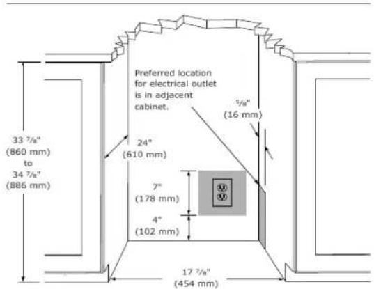
See CUTOUT & PRODUCT DIMENSIONS for recommended receptacle location.
Cutout & Product Dimensions
PREPARE SITE
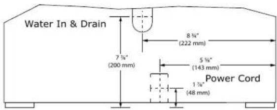
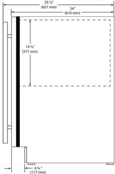
Your U-Line product has been designed for either freestanding or built-in installation. When built-in, your unit does not require additional air space for top, sides, or rear. However, the front grille must NOT be obstructed, and clearance is required for an electrical connection in the rear.

CAUTION
Unit can NOT be installed behind a closed cabinet door.
If you would like to align the face of the unit with other adjacent cabinet doors, you may need to alter the wall just behind the drain connection on the unit to accommodate the drain.
CUTOUT DIMENSIONS
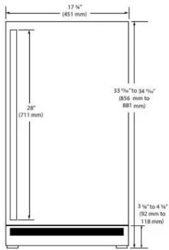
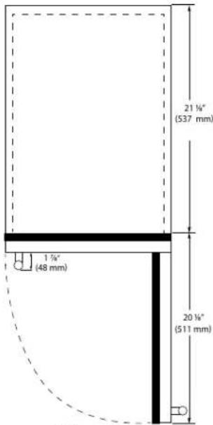
PRODUCT DIMENSIONS
REAR
SIDE
FRONT
TOP
Side-by-Side Installation
OTHER SITE REQUIREMENTS
Side-by-Side Installation
Units must operate from separate, properly grounded electrical receptacles placed according to each unit's electrical specifications requirements.
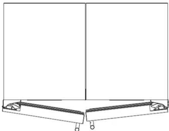
Cutout width for a side-by-side installation is the total of the widths listed under Cutout Dimensions in each unit's Installation Guide. Each door can be opened individually (one at a time) without interference.
natural_image
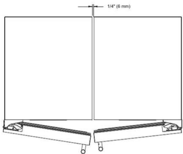
Pure technical line drawing of a structural frame with no text, numbers, or symbolsHowever, to ensure unobstructed door swing (opening both doors at the same time), 1/4" (6.4 mm) of space needs to be maintained between the units.
Hinge-by-Hinge Installation (Mullion)
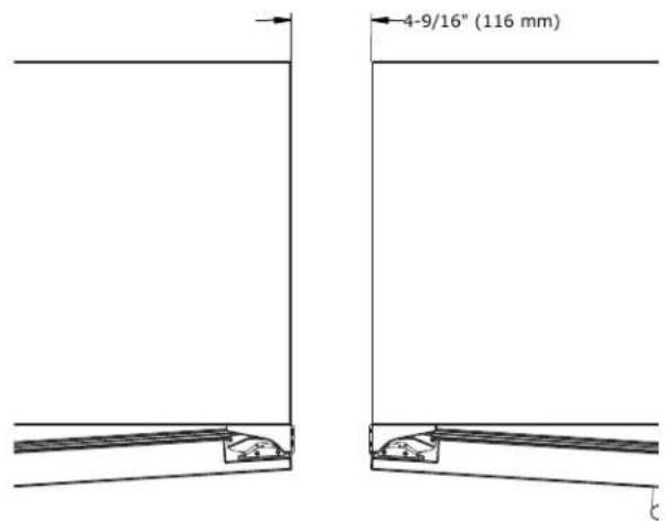
When installing two units hinge-by-hinge, 13/16" (22 mm) is required for integrated models. Additional space may be needed for any knobs, pulls or handles installed.
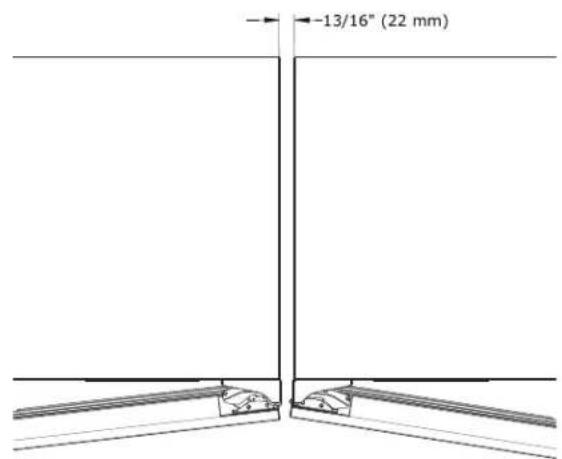
Stainless steel models which include the standard stainless handle will require 4-9/16" (116 mm) to allow both doors to open to 90° at the same time.
Water Hookup
PREPARE PLUMBING
The water valve uses a standard 1/4" (6.35 mm) compression fitting. U-Line recommends using accessory water hook up kit - part # ULAWATERHOOKUP. The kit includes a 10' (3 m) braided flexible water supply line and a brass hose fitting.

WARNING
Prior to installation, determine if this product contains a gravity style drain or factory installed drain pump. Products without a drain pump may only use a gravity style drain. Failure to connect water supply or drain line connections properly may result in water leakage, personal injury, and/or property damage. Disconnect power and turn off water to the unit before attempting to alter these connections. These connections are the responsibility of the owner and must be connected per local plumbing code. If you are uncertain of how to safely and properly install this product, contact a licensed plumber.
Water Supply Connection

WARNING
Connect to potable water supply only.

CAUTION
Review, obey, and understand the local plumbing codes before you install your unit. Connect to the cold water supply. The water pressure should be between 20 and 120 psi (138 and 827 kPa). The water line MUST have a shut-off valve on the supply line.

CAUTION
Do not use any plastic water supply line. The line is under pressure at all times. Plastic may crack or rupture with age and cause damage to your home.

CAUTION
Do not use tape or joint compound when attaching a braided flexible water supply line that includes a rubber gasket. The gasket provides an adequate seal – other materials could cause blockage of the valve.
Failure to follow recommendations and instructions may result in damage and/or harm, flooding or void the product warranty.

CAUTION
Turn off water supply and disconnect electrical supply to unit prior to installation.
Use caution when handling back panel. The edges could be sharp.
- Turn off water supply and disconnect electrical supply to product prior to attempting installation.
- Remove the grille/access panel in the front and the back panel.
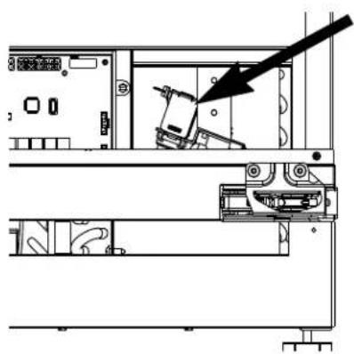
- Locate water valve in the front of the unit and thread water supply line through.
NOTICE
Route the water supply line
natural_image
Technical line drawing of a mechanical assembly with an arrow pointing to a component (no text or symbols present)through the unit so it does not come into contact with any internal components other than the solenoid valve. Normal operation creates some vibration. A water supply line contacting an internal component or cabinet wall can cause excessive noise during operation or damage to the line.
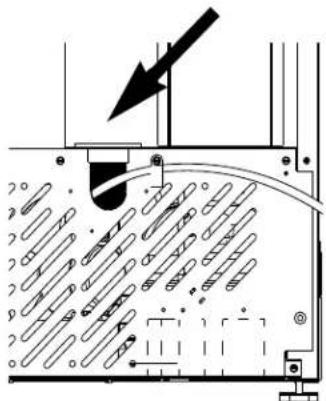
- On the back panel, exit waterline in same location as drain line.
natural_image
Diagram of a mechanical device with internal components and an arrow indicating direction (no text or symbols)- Turn on water supply and check for leaks
- Reinstall back panel and grille/front access panel.
- Install retaining clip.
Drain
Model numbers including "CL" or "NB" do not include a factory installed drain pump.
Model numbers including "CP" or "NP" include a factory installed drain pump.
DRAIN CONNECTION

CAUTION
If your U-Line unit did not come with a factory installed drain pump you must use a gravity style drain connection. For assistance in determining if your unit has a pump please contact U-Line. The floor drain must be large enough to accommodate drainage from all attached drains. Follow these guidelines when installing drain lines to prevent water from flowing back into the ice maker storage bin and/or potentially flowing onto the floor, which may result in personal injury or property damage
NOTICE
Drain can NOT be located directly below the unit. Unit has a solid base that will not allow the unit to drain below itself.
There is a possibility that hose connections may have loosened during shipment.
Verify all connections and fittings are free from leaks.

CAUTION
This equipment is to be installed with adequate backflow protection to comply with applicable federal, state and local codes
GRAVITY DRAIN
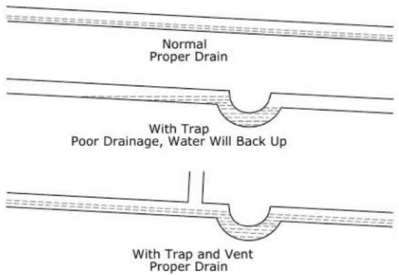
A gravity drain may be used if:
Drain line has at least a 1" drop per 48" (approximately 2 cm drop per 100 cm) of run.
Drain line does not create traps and is vented per local code.
- Cut the pre-installed drain tube to length.
- Connect to your local plumbing per the local code.
- If necessary, insulate drain line to prevent condensation.

CAUTION
Failure to connect water supply or drain line connections properly can result in personal injury and property damage. Gravity drain connections must be routed downward from the rest of the unit at the rate of 1/4" per foot (1 cm per 50 cm).
FACTORY INSTALLED DRAIN PUMP
If your drain line will run up to a stand pipe, disposal or spigot assembly, or does not otherwise meet the requirements for a gravity drain, you may have ordered a pre-installed U-Line P60 drain pump.
If you need to install a P60 drain pump into your unit, see DRAIN PUMP section in the User Manual.
See below for typical installations requiring a drain pump.
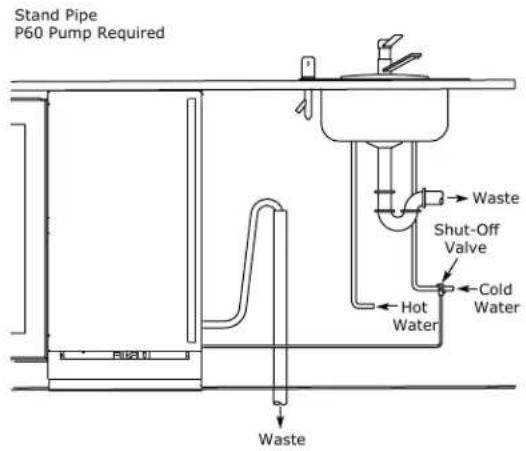
Disposal Assembly P60 Pump Required
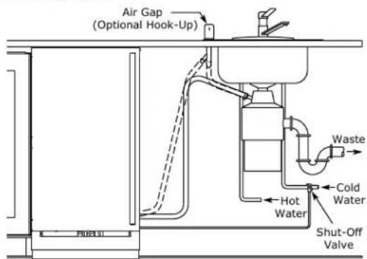
Y-Branch Tailpiece P60 Pump Required
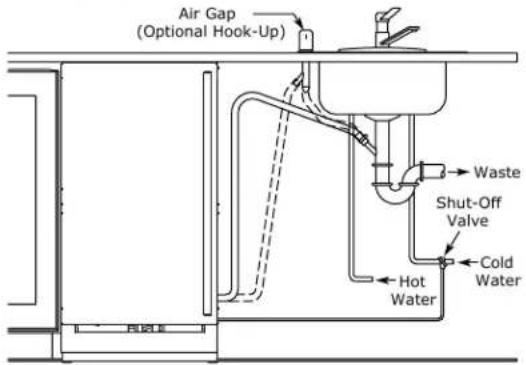
NOTICE
The maximum lift for the P60 drain pump is 10 feet. This must be done as close to the rear of the unit as possible.
SAFETY • INSTALLATION & INTEGRATION • OPERATING INSTRUCTIONS • MAINTENANCE • SERVICE
Drain Pump
NOTICE
PLEASE READ this instruction completely before attempting to install or operate the unit. Improper hook-up can result in substantial property damage! If you are unsure of your ability to safely connect the drain pump to the unit, consult a licensed plumber for assistance. Use these instructions to install the U-Line P60-00 drain pump in the U-Line Clear Ice Machine (unit). The drain pump should be installed before installing the unit.
- The U-Line P60-00 drain pump is designed to be used exclusively on the U-Line Clear Ice Machine and is UL recognized only for use on the U-Line Clear Ice Machine.
- U-Line Corporation assumes no warranties or responsibility, whether express or implied, if the P60-00 drain pump is used on another ice machine or product for which it is not UL recognized or listed.
- Modification of the P60-00 drain pump will void all warranties.
NOTICE
Keep your proof of purchase for warranty purposes.
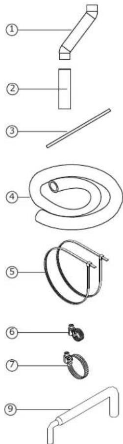
INCLUDED IN KIT:
- 1x S-shaped Drain Tube (Not used)
- 1x Straight Drain Tube
- 1x Vent Tube
- 1x Braided Discharge Tube (Not included in pump kit. Ice Machine ships with discharge tube installed.)
- 2x Vent tube Zip Ties
- 2x Small Worm Gear Clamps
- 1x Large Worm Gear Clamp
- 1x P60 Pump
- 1x Discharge Tub (Used on older models only)
TOOLS REQUIRED:
• 1/4" x 6" Blade Screwdriver
- Adjustable Pliers
- 1/4" Nut Drive
SAFETY • INSTALLATION & INTEGRATION • OPERATING INSTRUCTIONS • MAINTENANCE • SERVICE
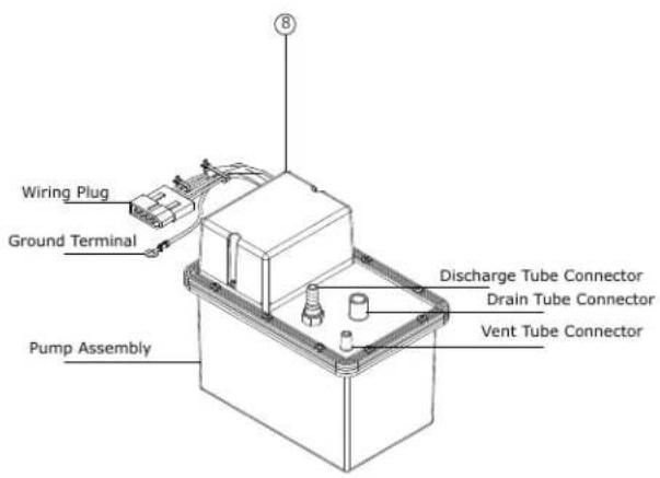
INSTALLATION PROCEDURE

WARNING
To prevent accidental electrocution, make certain that the floor surfaces surrounding the unit are dry whenever power/electricity is removed from, or applied to the unit.
- Disconnect your unit from its electrical outlet/socket.
- Use a screwdriver, push the power/electric cord grommet through its seat in the back panel.
- Using a screwdriver or 1/4" nut driver, remove the 12 screws from the back panel.
- Remove the drain line/pipe from the storage bin drain nipple. Save the clamp for pump installation.

CAUTION
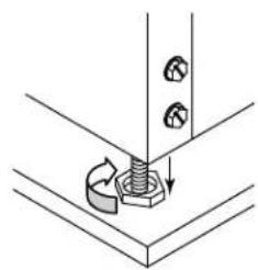
To prevent damage to the pump, leave sufficient space between leveling leg and pump.
- Fully extend the left rear leveling foot.
Note: Slide clamp on hose end before installing hose. Do not tighten clamp until pump and hoses have been installed.
- Install the 3 hoses and hose clamps to the pump assembly as shown below. Do not tighten clamps at this time.
natural_image
Technical diagram showing a bolt installation with arrows indicating direction (no text or labels)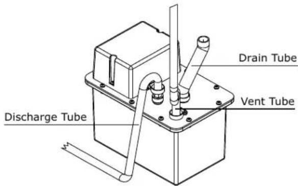
-
Remove the protective paper from the adhesive strip and carefully set pump inside of unit.
-
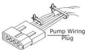
Unplug jumper block from ice machine wiring harness (jumper block has a single pink wire). Discard jumper block.
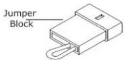
- Connect pump wiring plug to the ice machine wiring harness connector, where the jumper block was removed. The connector is keyed and can only be inserted one way.

CAUTION
When working with tools inside of unit, be careful so as not to nick or damage any refrigerant lines/pipes or wires.
SAFETY • INSTALLATION & INTEGRATION • OPERATING INSTRUCTIONS • MAINTENANCE • SERVICE

WARNING
The back panel serves as a guard. Do not put your hands inside the ice machine cabinet or attempt to touch any components except the discharge tube during testing.

CAUTION
Failure to properly secure the vent tube will result in water damage to the unit and surrounding areas. Do not allow vent tube to kink, bend or be obstructed in any way.

CAUTION
Vent tube must be straight and parallel to insulated tubes. Do not over-tighten the plastic tie wraps. Over-tightening can pinch vent tube closed or cut into insulation.
-
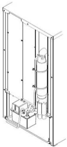
Route the vent tube up the back of the unit, next to the insulated tubes. Secure vent tube vertical to the insulated tubes using plastic tie wraps.
-
Connect pump drain tube to storage bin drain nipple with clamp removed from step 3. Ensure that no kinks are present in the tube.
-
Tighten the clamps on the drain, discharge, and vent tubes with a screwdriver or 1/4" nut driver.
natural_image
Technical line drawing of a mechanical assembly with vertical supports and internal components (no text or symbols)General Installation
LEVELING INFORMATION
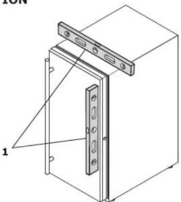
- Use a level to confirm the unit is level. Level should be placed along top edge and side edge as shown.
natural_image
Technical line drawing of a door frame with mounting brackets and a labeled component (no text or symbols present)- If the unit is not level, adjust the legs on the corners of the unit as necessary.
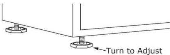
- Confirm the unit is level after each adjustment and repeat the previous steps as needed.
INSTALLATION TIP
If the room floor is higher than the floor in the cutout opening, adjust the rear legs to achieve a total unit rear height of 18 " (3 mm) less than opening's rear height. Shorten the unit height in the front by adjusting the front legs. This allows the unit to be gently tipped into the opening. Readjust the front legs to level the unit after it is correctly positioned in the opening.
INSTALLATION
- Plug in the power/electrical cord.
- Gently push the unit into position. Be careful not to entangle the cord or water and drain lines, if applicable.
- Re-check the leveling, from front to back and side to side. Make any necessary adjustments. The unit's top surface should be approximately 18 " (3 mm) below the countertop.
- Install the anti-tip bracket.
- Remove interior packing material and wipe out the inside of the unit with a clean, water-dampened cloth.
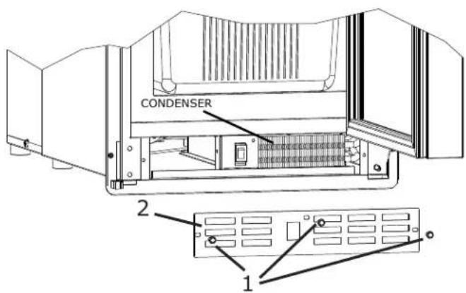
Grille Installation
REMOVING AND INSTALLING GRILLE

WARNING
Disconnect electric power to the unit before removing the grille.
When using the unit, the grille must be installed.

WARNING
Do NOT touch the condenser fins. The condenser fins are SHARP and can be easily damaged.
Removing the grille
- Disconnect power to the unit.
- Remove the three screws (1).
- Remove grille (2) from unit.
Installing the grille
- Align cabinet and grille holes and secure, but do not over tighten grille screws (1).
- Reconnect power to the unit.
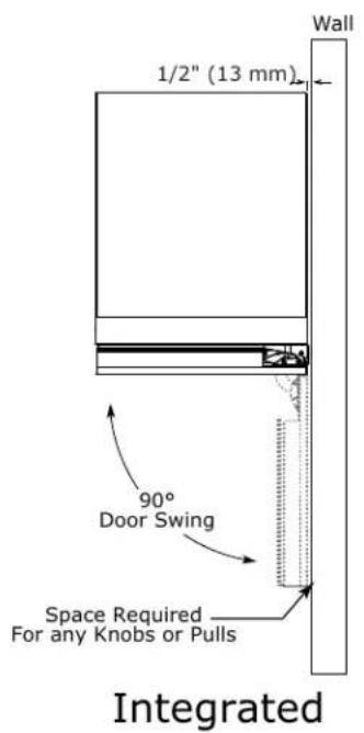
Door Swing
For Integrated models that are installed adjacent to a wall, 1/2" (13 mm) clearance is recommended from wall on hinge side to allow the door to open 90°. Allow for additional space for any knobs or pulls installed on the integrated panel/frame.
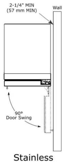
Stainless Steel models that are installed adjacent to a wall require 2-1/4" (57 mm) door clearance on hinge side to allow for door handle.
Units have a zero clearance when installed adjacent to cabinets.
Door Adjustments
DOOR ALIGNMENT AND ADJUSTMENT
Align and adjust the door if it is not level or not sealing properly. If the door is not sealed, the unit may not cool properly, or excessive frost or condensation may form in the interior.
NOTICE
Properly aligned, the door's gasket should be firmly in contact with the cabinet all the way around the door (no gaps). Carefully examine the door's gasket to ensure that it is firmly in contact with the cabinet. Also make sure the door gasket is not pinched on the hinge side of the door.

CAUTION
Do not attempt to use the door to raise or pivot your unit. This would put excessive stress on the hinge system.
Alignment and Adjustment Procedure
- Open door and remove gasket near the hinges.
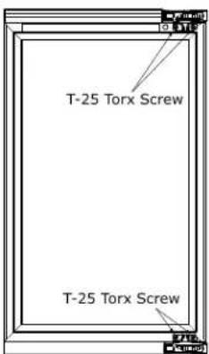
- Using a T-25 Torx bit, loosen each pair of Torx head screws both the upper and lower hinge plates.
- Square and align door as necessary.
- Tighten Torx head screws on hinge.
- Reinstall gasket into the channel starting at the corner.
REVERSING THE DOOR
- Open door.
- Using T-25 Torx bit loosen screw #1 and remove screw #2 on top and bottom hinge. Slide and remove the door from the unit.
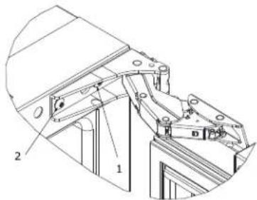
Note: One hinge includes a metal spacer. Spacer must be used with that hinge when reversing the door.
- Remove caps from screw heads on opposite side (2 on top and 2 on bottom). Using #2 Phillips bit, remove the 4 underlying screws. Reinstall the screws and caps on the opposite side.
- Partially install screw #1 in the outer most holes on top and bottom. Rotate door 180o, align hinge over screw #1 and slide/seat into position. Reinstall screw #2 on top and bottom. Tighten both screws and install hinge cover.
Align and adjust the door:
Align and adjust the door (see DOOR ALIGNMENT AND ADJUSTMENT).
First Use
All U-Line controls are preset at the factory. Initial startup requires no adjustments. See CONTROL OPERATION section for more details.
NOTICE
U-Line recommends discarding the ice produced during the first two to three hours of operation to avoid possible dirt or scale that may dislodge from the water line.
When plugged in, the unit will begin operating under the factory default settings. If the unit was turned off during installation, simply press ⏻ and the unit will immediately switch on. To turn the unit off, press ⏻ and release.
Control Operation
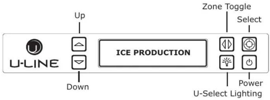
CONTROL FUNCTION GUIDE
| FUNCTION | COMMAND | DISPLAY/OPTIONS |
| OFF | Press ⏻ and hold | Display will count down from 5 to off. |
| ON | Press ⏻ and release | Unit will come on immediately. |
| Adjust lighting | Press ⏱ to adjust lighting | Press △ or ▽ to set low, medium or high. |
| Customer menu | Press ⏻ and hold for 5 seconds | Press △ or ▽ to scroll through menu. |
| Service menu | Press △ or ◇ and hold for 5 seconds | Press △ or ▽ to scroll through menu. |
U-SELECT® CONTROL
Digital Display
The 3000 Series units are controlled by a feature rich, advanced OLED display control unit. The control panel allows adjustment to temperature set point, access to Energy Saver Mode, internal temperature readings, and many other features.
U-Select Lighting
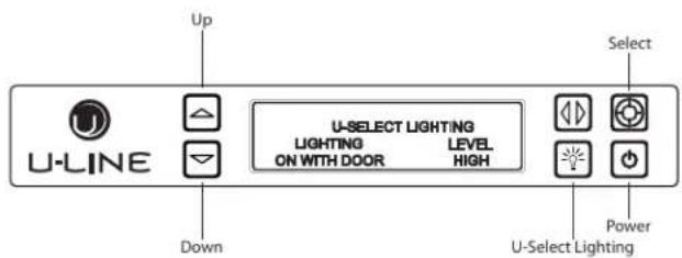
-
To begin, press ☐ to enter the lighting menu.
-
Press ☑ or ☑ to cycle through each available brightness setting (Low, Medium or High).
- Press ☐ to cycle through each available timer setting. Selections include "On With Door", "On 3 Hours", "On 6 Hours", or "On 24 Hours".
- To exit, press 📷 or simply wait for the menu to time out.
CUSTOMER MENU
The 3000 Series of U-Line undercounter refrigeration appliances contains a feature rich customer menu. The Customer Menu allows access to a series of advanced features including Energy Saver Mode, Sabbath Mode, actual temperature readings as well as a method to restore factory defaults.
3000 Series - Customer Menu
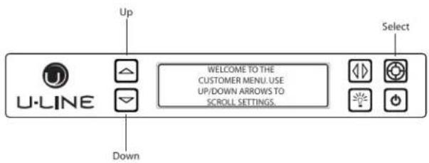
- To access the Customer Menu hold 📷 for 5 seconds.
- Press 🔒 or 📋 to scroll through available selections.
- Press 🔒 to enter selected sub-menu.
- To exit Customer Menu, press ☑ to scroll to the bottom of the display and press 🔒 to select "Exit".
Actual Temps

The Actual Temps option displays the actual temperature of the ice bin and condenser, as well as ambient temperature.
- To view actual temperature, press 🔒 and select "Actual Temps" from the Customer Menu.
- Press 🔒 or 📋 to scroll through available information.
- To return to the Customer Menu, press 🔒 and select "Return to Menu".
Energy Saver Mode
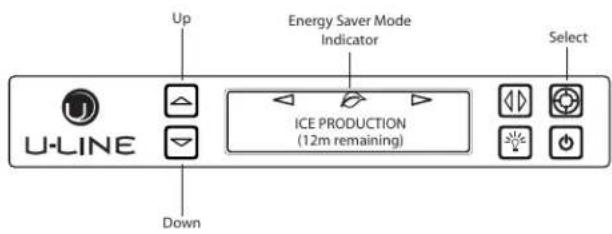
Energy Saver mode reduces overall energy consumption by reducing the amount of ice stored in the bin, along with decreasing the lighting.
- To enter Energy Saver Mode, first select Energy Saver from the Customer Menu.
- Press ☑ to select "Off" in the menu.
- Press
- Press ▲ or ▼ to change the selection from Off to On.
- Press 🔒 to confirm your selection.
- To return to the Customer Menu, press 🔒 and select "Return to Menu".
- To cancel Energy Saver Mode simply return to the Customer Menu, select Energy Saver and change "On" to "Off".
Languages
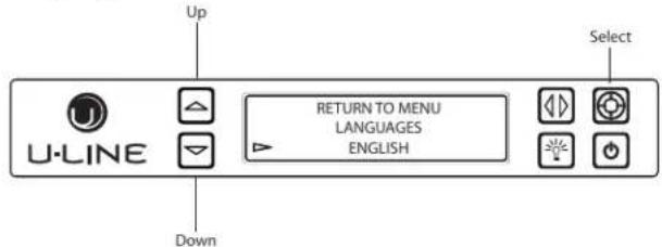
The U-Line 3000 Series of models supports a number of display languages including English, Spanish, French, German and Italian.
- To change display language select Languages from the Customer Menu.
- Press ☑ to select "English".
- Press 📋. "English" will begin to flash.
- Press 🔒 or ☑ to cycle through the available languages.
- Press 🔒 to confirm your choice.
Sound Level
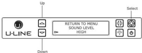
Audible alarms and alert tones support four different Sound Level settings, High, Medium, Low, and Off.
To select a new tone level, enter the Sound Level Menu from the Customer Menu.
-
Press ☐ or ☑ to select the current sound level.
-
Press ☐. The current setting will begin to flash.
- Press ☐ or ☑ to select a different level.
- Press 🔒 to confirm your choice.
- Press ☑ to select "Degrees".
- Press ☐. The selection will begin to flash.
- Press ☐ or ☑ to select between °F (Fahrenheit) or °C (Celsius).
- Press ☐ to confirm your choice.
Clean Cycle
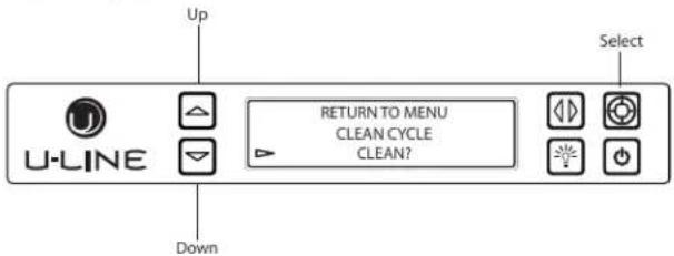
A clean cycle can be initiated through this menu. Once the cleaning cycle starts, the cycle cannot be stopped until complete.
To initiate a clean cycle, select "Clean Cycle" from the Customer Menu. Please refer to CLEANING section regarding proper cleaning procedure.
- Press ☑ to select "Clean Cycle".
- Press ☐. The clean cycle will now begin.
- Refer to CLEANING section regarding proper cleaning procedure.
Silent Mode
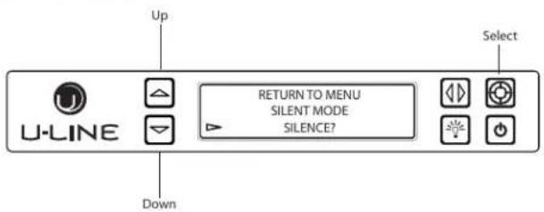
Users can halt ice production for 3 hours with an option called "Silent Mode" in the Customer Menu. Silent Mode will begin once the current ice making cycle is complete. After 3 hours in Silent Mode, normal ice production will continue.
NOTE: Silent Mode will not silence any alerts.
To initiate Silent Mode, enter Silent Mode Menu from within the Customer Menu.
To activate Silent Mode:
- Press ☑ to select "Silence?".
- Press 📋. Silent Mode will now begin.
To cancel Silent Mode:
- Press ☑ to select "Cancel?".
- Press 🔒. Silent Mode will end.
Ice Adjust
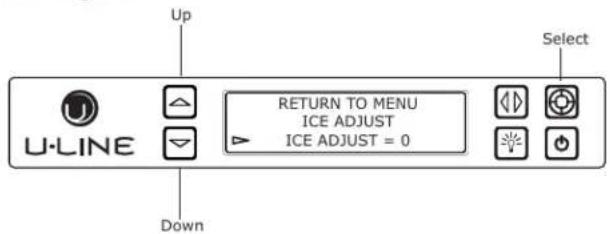
The Ice Adjust option adjusts ice thickness by adding or subtracting up to 5 minutes of ice production.
To change the ice thickness, enter the Ice Adjust Menu from within the Customer Menu.
To adjust thickness:
- Press ☑ to select "Ice Adjust".
- Press ☐. The selection will begin to flash.
- Press ☑ to make the ice thicker or ☑ to make the ice thinner.
- Press 🔒 to confirm your choice.
Help
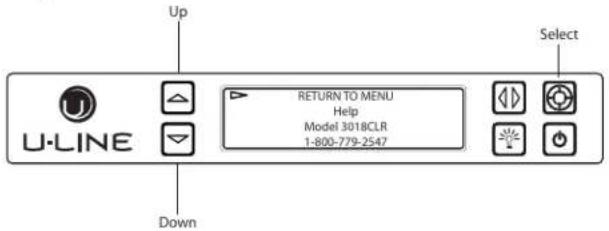
To access the Help Menu, select "Help" from the Customer Menu. Press 🔒 or ☑ to scroll through available information.
To return to the Customer Menu, press 🔒 to select "Return to Menu" and press 🔒 to confirm.
Ice
ICE CUBE THICKNESS ADJUSTMENT
NOTICE
Ice thickness adjustment should only be made one increment at a time. Allow ice maker production to stabilize for 24 hours before rechecking ice thickness.
Ice is produced in layers resulting in a clear cube. Ice in bin may develop surface frost which disappears when cube is placed in liquid.
Ice cubes in any given batch will vary, so it is necessary to choose cubes from the sample area for comparison when making adjustments.
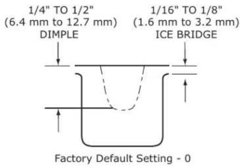
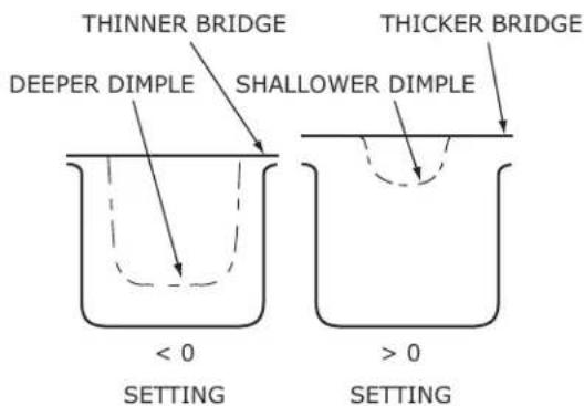
The ice cube thickness is factory set for best overall performance. The factory setting "0" is designed to maintain an ice bridge of approximately 1/16" to 1/8" (1.6 mm to 3.2 mm) under normal conditions, resulting in a dimple of approximately 1/4" to 1/2" (6.4 mm to 12.7 mm) in depth. A fuller cube with less of a dimple results in a thicker ice bridge. As the ice bridge thickens, the tendency for the cubes to stay together as a slab increases. A bridge thicker than 1/8" (3.2 mm) may cause cubes to overfill the ice bucket.
32 ice cubes are formed on a 4 x 8 slab during each cycle. Each cycle takes approximately 15-20 minutes at the default cube thickness (0).
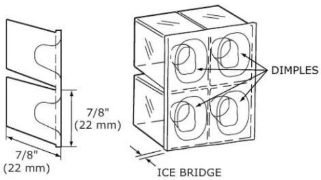
Your clear ice machine is pre-set to produce ice between the optimal dimensions illustrated below:
Cube Details
ICE ADJUST
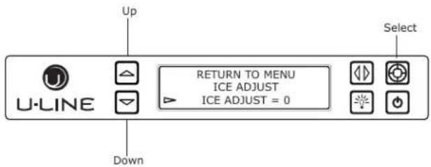
Adjust ice thickness as follows:
- Press △ and Ⓞ and hold for 5 seconds to enter the Customer Menu.
- Press ☑ to select "Ice Adjust".
- Press ☐. The selection will begin to flash.
- Press 🔒 to make the ice thicker or 🔑 to make the ice thinner. Press 🔒 to confirm your choice.
Airflow and Product Loading
NOTICE
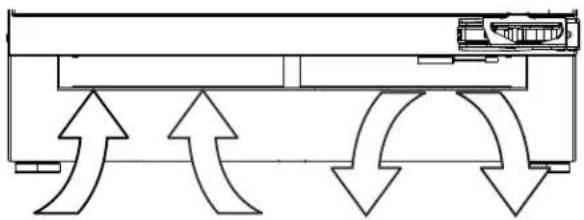
The unit requires proper airflow to perform at its highest efficiency. Do not block the front grille at any time, or the unit will not perform as expected. Do not install the unit behind a door.
natural_image
Pure technical diagram showing airflow or fluid flow between two rectangular components with directional arrows (no text or symbols)Cleaning
EXTERIOR CLEANING
Vinyl Clad (Black or White) Models
Clean surfaces with a mild detergent and warm water solution. Do not use solvent-based or abrasive cleaners. Use a soft sponge and rinse with clean water. Wipe with a soft, clean towel to prevent water spotting.
Clean any glass surfaces with a non-chlorine glass cleaner.
Stainless Models
Stainless door panels, handles and frames can discolor when exposed to chlorine gas, pool chemicals, saltwater or cleaners with bleach.
Keep your stainless unit looking new by cleaning with a good quality all-in-one stainless steel cleaner and polish monthly. For best results use Claire® Stainless Steel Polish and Cleaner. Comparable products are acceptable. Frequent cleaning will remove surface contamination that could lead to rust. Some installations may require cleaning weekly.
Do not clean with steel wool pads.
Do not use stainless steel cleaners or polishes on any glass surfaces.
Clean any glass surfaces with a non-chlorine glass cleaner.
Do not use cleaners not specifically intended for stainless steel on stainless surfaces (this includes glass, tile and counter cleaners).
If any surface discoloring or rusting appears, clean it quickly with Bon-Ami ^® or Barkeepers Friend Cleanser ^® and a nonabrasive cloth. Always clean with the grain. Always finish with Claire ^® Stainless Steel Polish and Cleaner or comparable product to prevent further problems.
Using abrasive pads such as ScotchBrite™ will cause the graining in the stainless steel to become blurred.
Rust not cleaned up promptly can penetrate the surface of the stainless steel and complete removal of the rust may not be possible.
Integrated Models
To clean integrated panels, use household cleaner per the cabinet manufacturer's recommendations.
INTERIOR CLEANING
Disconnect power to the unit.
Clean the interior and all removed components using a mild nonabrasive detergent and warm water solution applied with a soft sponge or non-abrasive cloth.
Rinse the interior using a soft sponge and clean water.
Do not use any solvent-based or abrasive cleaners. These types of cleaners may transfer taste and/or odor to the interior products and damage or discolor the interior.
CLEAR ICE MACHINE CLEANING CYCLE
Your U-Line clear ice machine has an automatic clean alert function. Cleaning cycles should be run as notified. Otherwise, to maintain operational efficiency the unit should be cleaned every three months. Depending on water conditions, more frequent cleaning may be necessary. If the ice machine requires more frequent cleaning, consult a plumber to test the water quality and recommend appropriate treatment.

CAUTION
Wear rubber gloves and safety goggles and/or face shield when handling Ice Machine Cleaner.
NOTICE
Use only U-Line Ice Machine Cleaner (ULACLRCLEAN), available for purchase from u-line.com or your dealer. It is a violation of federal law to use this solution in a manner inconsistent with its labeling. Use of any other cleaner can ruin the finish of the evaporator and will void the warranty. Read and understand all labels printed on the package before use.
U-Line Ice Machine Cleaner is used to remove lime scale and other mineral deposits. Refer to the following steps to initiate the self-cleaning cycle.

CAUTION
Never use anything to force ice from the evaporator. Damage may result.
- Turn the ice machine off and allow any ice to melt off of the evaporator.
- Remove all ice from the storage bin.
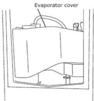
- Remove evaporator cover.
-
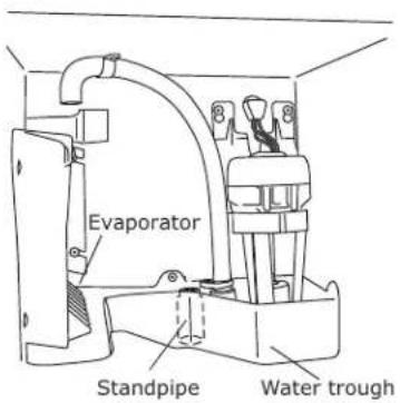
Remove the standpipe by lifting it up while using a slight back and forth motion to loosen it from the drain hole. The water in the reservoir will flow down the drain.
-
Re-install the standpipe into the water trough.
-
Clean the Interior Bin as follows:
-
Dilute one packet of CLR cleaner into two quarts of water.
- Using a sponge or cloth, clean interior of ice bin, tubing and door. This cleaner will remove all mineral deposits and other contaminants from the surfaces.
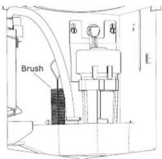
- Using a bottle brush, clean out the trough drain tube and pump tubing where needed.
- Turn unit on by pressing ⏻.
-
Place the unit into CLEAN mode by holding 📋 for 5 seconds.
-
When water begins flowing over the evaporator (approximately 3 minutes), pour 1 packet of CLR cleaner into the water trough. The cleaning process will last approximately 45 minutes.
-
Dilute 1 tablespoon bleach in 1 gallon of warm water. Apply this solution to the entire inside of the storage area. Then rinse thoroughly with water.
The unit will resume operation approximately 15 minutes after the automated cleaning process is completed. The water fill valve will energize, fill the water reservoir, and shut-off after three minutes. The compressor begins to operate and water flows over the evaporator assembly (ice mold). Initially, the water flow may not be uniform, causing uneven sized cubes or water to spill into the ice storage bin. This is a normal situation that will correct itself within the first 24 hours of operation.
NOTICE
Discard all ice produced in the first harvest.
Should power to the unit be interrupted during the self-clean cycle, it will be necessary to repeat the complete cleaning cycle after power is restored.
REFRESH KIT
Due to variations in water quality or inadequate maintenance your unit may become excessively coated in lime scale or calcium. U-Line offers a cost effective refresh kit which replaces many interior components and will return your unit to like new condition. Refresh kits may be ordered from your local distributor and installed by your local service company. For information on your local distributor or service company please visit www.u-line.com.
Cleaning Condenser
INTERVAL - EVERY SIX MONTHS
To maintain operational efficiency, keep the front grille free of dust and lint, and clean the condenser when necessary. Depending on environmental conditions, more or less frequent cleaning may be necessary.

WARNING
Disconnect electric power to the unit before cleaning the condenser.

WARNING
DO NOT touch the condenser fins. The condenser fins are SHARP and can be easily damaged.
NOTICE
DO NOT use any type of cleaner on the condenser unit.
- Remove the grille. (See GRILLE INSTALLATION).
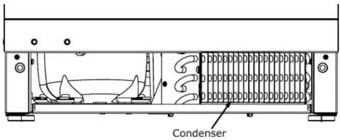
- Clean the condenser coil using a soft brush with a "combing" action or vacuum cleaner. Do not touch the condenser coil.
- Install the grille.
Extended Non-Use
VACATION/HOLIDAY, PROLONGED SHUTDOWN
The following steps are recommended for periods of extended non-use:
- Remove all consumable content from the unit.
- Disconnect the power cord from its outlet/socket and leave it disconnected until the unit is returned to service.
- Turn off the water supply.
- If ice is on the evaporator, allow ice to thaw naturally.
- Clean and dry the interior of the cabinet. Ensure all water has been removed from the unit.
- Disconnect the water and drain line (if applicable) making sure all water is removed from the lines.
- The door must remain open to prevent formation of mold and mildew. Open door a minimum of 2" (50 mm) to provide the necessary ventilation.
WINTERIZATION
If the unit will be exposed to temperatures of 40^ F ( 5^ C) or less, the steps above must be followed. In addition, P60 drain pumps in clear ice machines must be drained according to the following procedure:
- Remove the drain pump from the ice machine.
- Drain the water in the pump's reservoir by turning the pump upside down and allowing the water to drain through the pump's inlet and vent tube fittings.
- After water is drained, reinstall the drain pump and reattach all connections.
For questions regarding winterization, please call U-Line at 414.354.0300.

CAUTION
Damage caused by freezing temperatures is not covered by the warranty.
Do not put anti-freeze in your unit.
SAFETY • INSTALLATION & INTEGRATION • OPERATING INSTRUCTIONS • MAINTENANCE • SERVICE
Wire Diagram
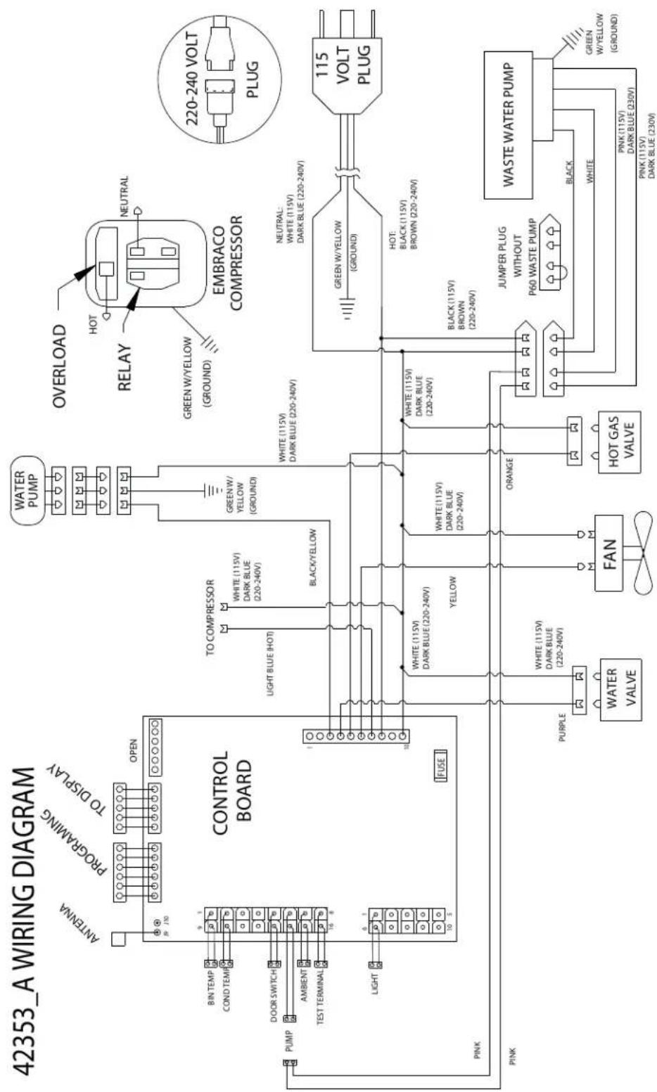
flowchart
graph TD
    A["CONTROL BOARD"] --> B["ANTenna"]
    A --> C["PROGRAMING"]
    A --> D["TO DISPLAY"]
    A --> E["PUMP"]
    A --> F["MIN TEMP"]
    A --> G["COND TEMPT"]
    A --> H["DOOR SWITCH"]
    A --> I["AMBIENT"]
    A --> J["TEST TERMINAL"]
    A --> K["LIGHT"]
    A --> L["FUSE"]
    A --> M["PINK"]
    A --> N["PINK"]
    A --> O["PURPLE"]
    A --> P["PUMA"]
    A --> Q["PUMA"]
    A --> R["PUMA"]
    A --> S["PUMA"]
    A --> T["PUMA"]
    A --> U["PUMA"]
    A --> V["PUMA"]
    A --> W["PUMA"]
    A --> X["PUMA"]
    A --> Y["PUMA"]
    A --> Z["PUMA"]
    A --> AA["PUMA"]
    A --> AB["PUMA"]
    A --> AC["PUMA"]
    A --> AD["PUMA"]
    A --> AE["PUMA"]
    A --> AF["PUMA"]
    A --> AG["PUMA"]
    A --> AH["PUMA"]
    A --> AI["PUMA"]
    A --> AJ["PUMA"]
    A --> AK["PUMA"]
    A --> AL["PUMA"]
    A --> AM["PUMA"]
    A --> AN["PUMA"]
    A --> AO["PUMA"]
    A --> AP["PUMA"]
    A --> AQ["PUMA"]
    A --> AR["PUMA"]
    A --> AS["PUMA"]
    A --> AT["PUMA"]
    A --> AU["PUMA"]
    A --> AV["PUMA"]
    A --> AW["PUMA"]
    A --> AX["PUMA"]
    A --> AY["PUMA"]
    A --> AZ["PUMA"]
    A --> BA["PUMA"]
    A --> BB["PUMA"]
    A --> BC["PUMA"]
    A --> BD["PUMA"]
    A --> BE["PUMA"]
    A --> BF["PUMA"]
    A --> BG["PUMA"]
    A --> BH["PUMA"]
    A --> BI["PUMA"]
    A --> BJ["PUMA"]
    A --> BK["PUMA"]
    A --> BL["PUMA"]
    A --> BM["PUMA"]
    A --> BN["PUMA"]
    A --> BO["PUMA"]
    A --> BP["PUMA"]
    A --> BQ["PUMA"]
    A --> BR["PUMA"]
    A --> BS["PUMA"]
    A --> BT["PUMA"]
    A --> BU["PUMA"]
    A --> BV["PUMA"]
    A --> BW["PUMA"]
    A --> BX["PUMA"]
    A --> BY["PUMA"]
    A --> BZ["PUMA"]
    A --> CA["PUMA"]
    A --> CB["PUMA"]
    A --> CC["PUMA"]
    A --> CD["PUMA"]
    A --> CE["PUMA"]
    A --> CF["PUMA"]
    A --> CG["PUMA"]
    A --> CH["PUMA"]
    A --> CI["PUMA"]
    A --> CJ["PUMA"]
    A --> CK["PUMA"]
    A --> CL["PUMA"]
    A --> CD
    A --> CD
    style Control Board fill:#f9f,stroke:#333
    style EMBRACO_COMPressor fill:#ccf,stroke:#333
    style 115_VOLT_PLUG fill:#cfc,stroke:#333
    style 220-240_VOLT_PLUG fill:#fcc,stroke:#333
    style 115_VOLT_PLUG fill:#ffc,stroke:#333
    style 220-240_VOLT_PLUG fill:#fcc,stroke:#333
    style 115_VOLT_PLUG fill:#cfc,stroke:#333
    style 220-240_VOLT_PLUG fill:#fcc,stroke:#333
    style 115_VOLT_PLUG fill:#cfc,stroke:#333
    style 220-240_VOLT_PLUG fill:#fcc,stroke:#333
    style 115_VOLT_PLUG fill:#cfc,stroke:#333
    style PLUG fill:#fcc,stroke:#333
U-Line Corporation (U-Line) Limited Warranty
One Year Limited Warranty
For one year from the date of original purchase, this warranty covers all parts and labor to repair or replace any part of the product that proves to be defective in materials or workmanship. For products installed and used for normal residential use, material cosmetic defects are included in this warranty, with coverage limited to 60 days from the date of original purchase. All service provided by U-Line under the above warranty must be performed by a U-Line factory authorized servicer, unless otherwise specified by U-Line. Service provided during normal business hours.
Two Year Limited Warranty (5 Class Product)
For two years from the date of original purchase, this warranty covers all parts and labor to repair or replace any part of the product that proves to be defective in materials or workmanship. For products installed and used for normal residential use, material cosmetic defects are included in this warranty, with coverage limited to 60 days from the date of original purchase. All service provided by U-Line under the above warranty must be performed by a U-Line factory authorized servicer, unless otherwise specified by U-Line. Service provided during normal business hours.
Available Second & Third Year Limited Warranty
In addition to the standard one and two year warranties outlined above, U-Line offers a one year extension of the warranties from the date of purchase, free of charge. To take advantage of this extension, you must register your product with U-Line within 60 days from the date of purchase at u-line.com and provide proof of purchase.
Five Year Sealed System Limited Warranty
For five years from the date of original purchase, U-Line will repair or replace the following parts, labor not included, that prove to be defective in materials or workmanship: compressor, condenser, evaporator, drier, and all connecting tubing. All service provided by U-Line under the above warranty must be performed by a U-Line factory authorized servicer, unless otherwise specified by U-Line. Service provided during normal business hours.
Terms
These warranties apply only to products installed in any one of the fifty states of the United States, the District of Columbia, or the ten provinces of Canada. The warranties do not cover any parts or labor to correct any defect caused by negligence, accident or improper use, maintenance, installation, service, repair, acts of God, fire, flood or other natural disasters. The product must be installed, operated, and maintained in accordance with your product's User Guide.
The remedies described above for each warranty are the only ones that U-Line will provide, either under these warranties or under any warranty arising by operation of law. U-Line will not be responsible for any consequential or incidental damages arising from the breach of these warranties or any other warranty, whether express, implied, or statutory. Some states do not allow the exclusion or limitation of incidental or consequential damages, so the above limitation or exclusion may not apply to you. These warranties give you specific legal rights, and you may also have other rights which vary from state to state.
Any warranty that may be implied in connection with your purchase or use of the product, including any warranty of merchantability or any warranty fit for a particular purpose is limited to the duration of these warranties, and only extends to five years in duration for the parts described in the section related to the five year limited warranty above. Some states do not allow limitations on how long an implied warranty lasts, so the above limitations may not apply to you.
• The warranties only apply to the original purchaser and are non-transferable.
• The second, third, and five year warranties cover products installed and used for normal residential or designated marine use only.
• The warranties apply to units operated outside only if designed for outdoor use by model and serial number.
- U-Line Commercial products are covered by the one year and 5 year limited warranties and are not eligible for the second and third year limited warranties.
• Replacement water filters, light bulbs, and other consumable parts are not covered by these warranties.
- The start of U-Line's obligation is limited to four years after the shipment date from U-Line.
• In-home instruction on how to use your product is not covered by these warranties.
• Food, beverage, and medicine loss are not covered by these warranties.
- If the product is located in an area where U-Line factory authorized service is not available, you may be responsible for a trip charge or you may be required to bring the product to a U-Line factory authorized service location at your own cost and expense.
- Units purchased after use as floor displays, and/or certified reconditioned units, are covered by the limited one year warranty only and no coverage is provided for cosmetic defects.
• Signal issues related to Wi-Fi connectivity are not covered by these warranties.
For parts and service assistance, or to find U-Line factory authorized service near you, contact U-Line: 8900 N. 55^th Street, Milwaukee, WI 53223 • u-line.com • onlineservice@u-line.com • +1.414.354.0300
- USER GUIDE & SERVICE MANUAL
- Table of Contents
- Safety
- Installation
- Maintenance
- Operating Instructions
- Service
- WELCOME TO U-LINE
- PRODUCT INFORMATION
- PROPERTY DAMAGE / INJURY CONCERNS
- GENERAL INQUIRIES
- SERVICE & PARTS ASSISTANCE
- CONNECT WITH US
- Safety and Warning
- NOTICE
- SAFETY ALERT DEFINITIONS
- DANGER
- WARNING
- CAUTION
- CALIFORNIA PROPOSITION 65
- Disposal and Recycling
- Environmental Requirements
- Electrical
- Cutout & Product Dimensions
- PREPARE SITE
- Side-by-Side Installation
- OTHER SITE REQUIREMENTS
- Hinge-by-Hinge Installation (Mullion)
- Water Hookup
- PREPARE PLUMBING
- Drain
- DRAIN CONNECTION
- A gravity drain may be used if:
- FACTORY INSTALLED DRAIN PUMP
- Drain Pump
- INCLUDED IN KIT:
- TOOLS REQUIRED:
- INSTALLATION PROCEDURE
- General Installation
- LEVELING INFORMATION
- INSTALLATION TIP
- Grille Installation
- REMOVING AND INSTALLING GRILLE
- Removing the grille
- Installing the grille
- Door Swing
- Door Adjustments
- DOOR ALIGNMENT AND ADJUSTMENT
- Alignment and Adjustment Procedure
- REVERSING THE DOOR
- Align and adjust the door:
- First Use
- Control Operation
- CONTROL FUNCTION GUIDE
- U-SELECT® CONTROL
- Digital Display
- U-Select Lighting
- CUSTOMER MENU
- Series - Customer Menu
- Actual Temps
- Energy Saver Mode
- To activate Silent Mode:
- To cancel Silent Mode:
- To adjust thickness:
- Ice
- ICE CUBE THICKNESS ADJUSTMENT
- Airflow and Product Loading
- Cleaning
- EXTERIOR CLEANING
- Vinyl Clad (Black or White) Models
- Stainless Models
- Do not clean with steel wool pads.
- Do not use stainless steel cleaners or polishes on any glass surfaces.
- Do not use cleaners not specifically intended for stainless steel on stainless surfaces (this includes glass, tile and counter cleaners).
- Integrated Models
- INTERIOR CLEANING
- CLEAR ICE MACHINE CLEANING CYCLE
- REFRESH KIT
- Cleaning Condenser
- INTERVAL - EVERY SIX MONTHS
- Extended Non-Use
- VACATION/HOLIDAY, PROLONGED SHUTDOWN
- WINTERIZATION
- U-Line Corporation (U-Line) Limited Warranty
- One Year Limited Warranty
- Two Year Limited Warranty (5 Class Product)
- Available Second & Third Year Limited Warranty
- Five Year Sealed System Limited Warranty
- Terms
Brand : U-Line
Model : 3018CLRINT-00C
Category : Ice Maker