
HMa/E06 - Wireless audio transmitter Lectrosonics - Free user manual and instructions
Find the device manual for free HMa/E06 Lectrosonics in PDF.


| Product Type | Wireless Bodypack Transmitter |
| Brand | Lectrosonics |
| Model | HMa/E06 |
| Dimensions | 3.5 x 2.5 x 1.0 inches (88.9 x 63.5 x 25.4 mm) |
| Weight (with battery) | 6.5 oz (184 g) |
| Power Supply | 2 x AA alkaline or 1.5V rechargeable |
| Battery Life | Up to 8 hours with alkaline |
| Frequency Range | 470-614 MHz (UHF) |
| Frequency Selection | 256 selectable frequencies |
| Modulation | Digital Hybrid Wireless® |
| RF Power Output | 50 mW (switchable to 10 mW) |
| Audio Input | 3.5mm locking jack (mic/line) |
| Gain Adjustment | 40 dB range in 1 dB steps |
| Display | LCD with backlight |
| Sync Method | Infrared (IR) sync with receiver |
| Operating Range | Up to 300 ft (91 m) line-of-sight |
| Construction | Machined aluminum housing |
| Cleaning | Wipe with dry, lint-free cloth; avoid liquids |
| Safety | Use only approved batteries; keep away from moisture |
| Certifications | FCC, CE, RoHS |
| Warranty | 2 years (non-transferable) |
Frequently Asked Questions - HMa/E06 Lectrosonics
User questions about HMa/E06 Lectrosonics
0 question about this device. Answer the ones you know or ask your own.
Ask a new question about this device
Download the instructions for your Wireless audio transmitter in PDF format for free! Find your manual HMa/E06 - Lectrosonics and take your electronic device back in hand. On this page are published all the documents necessary for the use of your device. HMa/E06 by Lectrosonics.
USER MANUAL HMa/E06 Lectrosonics
With Digital Hybrid Wireless® Technology
HMa, HMa-941, HMa/E01, HMa/E02, HMa/E06, HMa/E07-941, HMa/X
Digital Hybrid Wireless® US Patent 7,225,135
CE UK CA
Follow Us On:


Fill in for your records:
Serial Number:
Purchase Date:
WARNING: Moisture, including talent's sweat, will damage the transmitter. Wrap the HMa in a plastic baggie or other protection to avoid damage or see HMCVR.

Thank you for selecting a Lectrosonics HMa Plug-On transmitter. The unique design provides several distinct features for professional applications:
• Outstanding RF operating range
- Superb audio quality
• Corrosion-resistant housing
- Programmable compatibility modes for use with a wide variety of different receivers
The Digital Hybrid Wireless ^® design (US Patent 7,225,135) combines 24-bit digital audio with analog FM resulting in a system that has the same operating range as analog systems, the same spectral efficiency as analog systems, the same long battery life as analog systems, plus the excellent audio fidelity typical of pure digital systems.
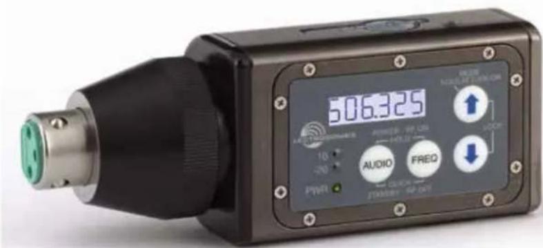
The transmitter uses a standard 3-pin XLR input jack for use with any microphone with a mating XLR connector. An LCD, membrane switches and multi-color LEDs on the control panel make input gain adjustments and frequency and compatibility mode selection quick and accurate, without having to view the receiver. The housing is machined from a solid aluminum block to provide a lightweight and rugged package. A special non-corrosive finish resists salt water exposure and perspiration in extreme environments.
The DSP-based design works with all Digital Hybrid receivers, and is backward compatible for use with Lectrosonics 200 and 100 Series, Mode 3, Mode 6, Mode 7, and IFB receivers and some other brands of analog wireless receivers. Companion receivers are covered in separate manuals. Your Lectrosonics representative can guide you through any compatibility concerns.
Table of Contents
General Technical Description .... 4
Digital Hybrid Wireless Technology.... 4
No Pre-Emphasis/De-Emphasis 4
Low Frequency Roll-Off....5
Input Limiter 5
Signal Encoding and Pilot Tone 5
Microprocessor and DSP 5
Compatibility Modes....5
Control Panel 5
Controls and Functions....6
LCD Screen 6
Power LED 6
Audio Input Jack....6
Battery Compartment....6
USB Port 6
IR Port 6
Modulation LEDs 6
Audio Button....6
Freq Button 6
UP/DOWN Arrows and Panel Lockout....6
Antenna 6
Battery Installation....7
Attaching/Removing a Microphone....7
Operating Instructions....8
Power Up and Boot Sequence....8
Power Down....8
Automatic Power Restore 8
Standby Mode....8
UP Button Menu 8
DOWN Button Menu....9
AUDIO Button Settings....10
FREQ Button Settings 11
Block 470/19 Frequency Overlap....11
Lock/Unlock Screen 12
Remote Control with "Dweedle Tones" 12
LectroRM....13
Supplied & Optional Accessories.... 14
P/N 21750 Barrel Adapter....14
MCA-M30 Barrel Adapter 14
PHTRAN3 14
MCA5X 15
MCA-TPOWER....15
HMCVR/HMCVR-BLK 15
Specifications and Features....16
Firmware Update....17
Troubleshooting....19
Service and Repair 21
Returning Units for Repair....21
EU Declaration of Conformity 22
Additional Compliance Notices....23
FCC Compliance:
This device complies with FCC radiation exposure limits as set forth for an uncontrolled environment. This device should be installed and operated so that its antenna(s) are not co-located or operating in conjunction with any other antenna or transmitter.
Notice to the End User:
The normal condition of using this device is to keep the hand at least 20mm away from the base of the microphone.
General Technical Description
The HMa transmitter uses a DSP controlled input limiter featuring a wide range dual envelope design which cleanly limits input signal peaks over 30 dB above full modulation. Switching power supplies to provide constant voltages to the transmitter circuits from the beginning (3 Volts) to the end (1.7 Volts) of battery life, and an ultra low noise input amplifier for quiet operation.
Digital Hybrid Wireless® Technology
All wireless links suffer from channel noise to some degree, and all wireless microphone systems seek to minimize the impact of that noise on the desired signal. Conventional analog systems use commanders for enhanced dynamic range, at the cost of subtle artifacts (known as "pumping" and "breathing"). Wholly digital systems defeat the noise by sending the audio information in digital form, at the cost of some combination of power, bandwidth and resistance to interference.
Lectrosonics Digital Hybrid Wireless systems overcome channel noise in a dramatically new way, digitally encoding the audio in the transmitter and decoding it in the receiver, yet still sending the encoded information via an analog FM wireless link. This proprietary algorithm is not a digital implementation of an analog compandor but a technique that can be accomplished only in the digital domain, even though the inputs and outputs are analog.
Channel noise still impacts received signal quality and will eventually overwhelm a receiver. Digital Hybrid Wireless ^® simply encodes the signal to use a noisy channel as efficiently and robustly as possible, yielding audio performance that rivals that of wholly digital systems, without the power and bandwidth problems inherent in digital transmission.
Because it uses an analog FM link, Digital Hybrid Wireless® enjoys all the benefits of conventional FM wireless systems, such as excellent range, efficient use of RF spectrum, and resistance to interference. However, unlike conventional FM systems, it does away with the analog compandor and its artifacts.
No Pre-Emphasis/De-Emphasis
The Digital Hybrid Wireless ^® design results in a signal-to-noise ratio high enough to preclude the need for conventional pre-emphasis (HF boost) in the transmitter and de-emphasis (HF roll-off) in the receiver. This eliminates the potential for distortion on signals with abundant high-frequency information.

flowchart
graph TD
    A["XLR Jack"] --> B["Input Amp"]
    B --> C["Hi-Lo Pass Filter"]
    C --> D["Audio"]
    D --> E["A-D Converter 11001001"]
    E --> F["Digital Signal Processor"]
    F --> G["Microprocessor"]
    G --> H["Phase Locked Loop"]
    H --> I["Voltage Controlled Oscillator"]
    I --> J["Final Amplifier"]
    J --> K["Switching Power Supply"]
    K --> L["3V Battery"]
    L --> M["Audio and Pilot Tone"]
    M --> N["Filter Amp"]
    N --> O["Output"]
    P["Bias Voltage 42V, 15V, 5V"] --> Q["Phantom Power"]
    Q --> R["+4V"]
    S["Shunt Limiter"] --> T["Digital Pot"]
    T --> U["Audio Level"]
    U --> V["Digital Signal Processor"]
    V --> W["Reference Crystal"]
    W --> X["Control Panel"]
    X --> Y["LCD"]
    Y --> Z["AUDIO"]
    Y --> AA["FREQ"]
    Y --> AB["UP"]
    Y --> AC["DWN"]
    Y --> AD["Bicolor Modulation LEDs"]
    X --> AE["Reference Crystal"]
    AE --> AF["Phase Locked Loop"]
    AF --> AG["Voltage Controlled Oscillator"]
    AG --> AH["Final Amplifier"]
Low Frequency Roll-Off
The low frequency roll-off can be set for a 3 dB down point at 35, 50, 70, 100, 120 and 150 Hz to control subsonic and very low frequency audio content in the audio. The actual roll-off frequency will vary slightly depending upon the low frequency response of the microphone.
Excessive low frequency content can drive the transmitter into limiting, or in the case of high level sound systems, even cause damage to loudspeaker systems. The roll-off is normally adjusted by ear while listening as the system is operating.
Input Limiter
A DSP-controlled analog audio limiter is employed before the analog-to-digital (A-D) converter. The limiter has a range of more than 30 dB for excellent overload protection. A dual release envelope makes the limiter acoustically transparent while maintaining low distortion. It can be thought of as two limiters in series, a fast attack and release limiter followed by a slow attack and release limiter. The limiter recovers quickly from brief transients, with no audible side effects, and also recovers slowly from sustained high levels, to keep audio distortion low and while preserving short term dynamics.
Signal Encoding and Pilot Tone
In addition to controlling the limiter, the DSP also encodes the digitized audio from the A-D converter and adds an ultrasonic pilot tone to control the receiver's squelch. A pilot tone squelch system provides a reliable method of keeping a receiver output muted (squelched) even in the presence of significant interference. When the system is operating in the hybrid mode, a different pilot tone frequency is generated for each carrier frequency in 100 kHz increments to prevent inadvertent squelch problems and simplify multi-channel coordination.
Microprocessor and DSP
A microprocessor monitors user command inputs from the control panel buttons and numerous other internal signals. It works intimately with the DSP to ensure the audio is encoded according to the selected Compatibility Mode and that the correct pilot tone is added to the encoded signal.
Compatibility Modes
The transmitter was designed to operate with Lectrosonics Digital Hybrid Wireless ^® receivers and will yield the best performance when doing so. However, due to the flexibility of digital signal processing, the transmitters can also operate in various compatibility modes (vary per specific model) for use with Lectrosonics Mode 3 and IFB receivers. It will also work with certain non-Lectrosonics receivers. Contact your sales representative or the factory for a complete list of compatible non-Lectrosonics receivers.
Control Panel
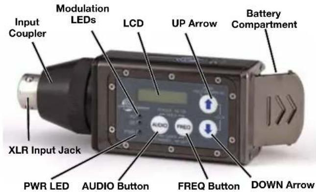
The control panel includes four membrane switches and an LCD screen to adjust the operational settings. Multicolor LEDs are used to indicate audio signal levels for accurate gain adjustment and for battery status.
Controls and Functions
LCD Screen
The LCD is a numeric-type Liquid Crystal Display with several screens that allow settings to be made with the AUDIO and FREQ buttons, and the UP and DOWN arrow buttons to configure the transmitter. The transmitter can be turned on in a "standby" mode with the carrier turned off to make adjustments without the risk of interfering with other wireless systems nearby.
Power LED
The PWR LED glows green when the batteries are good. The color changes to red when there is about 20 minutes of life left. When the LED begins to blink red, there are only a few minutes of life.
A weak battery will sometimes cause the PWR LED to glow green immediately after being put into the unit, but will soon discharge to the point where the LED will go red or shut off completely.
Audio Input Jack
The XLR input jack on the transmitter accommodates hand-held, shotgun and measurement microphones. Phantom power can be set at various levels for use with a wide variety of electret microphones.
Battery Compartment
The battery compartment door is made of machined aluminum and is hinged to the housing to prevent it being damaged or lost.
USB Port
USB Port for firmware updates in the field.
IR Port
IR (infrared) port for fast setup.
Modulation LEDs
The Modulation LEDs provide a visual indication of the input audio signal level from the microphone. These two bicolor LEDs can glow either red or green to indicate modulation levels. Full modulation (0 dB) occurs when the -20 LED first turns red.
Signal Level -20 LED -10 LED
| Less than -20 dB | ● Off | Off | ● | |
| -20 dB to -10 dB | Green | Off | ● | |
| -10 dB to +0 dB | ● Green | Green | ● | |
| +0 dB to +10 dB | Red | Green | ● | |
| Greater than +10 dB | ● Red | Red | ● |
Audio Button
The AUDIO button is used to display the audio level setting, low frequency roll-off and phantom power mode. Repeatedly pressing the button will cycle through the available settings, allowing the UP and DOWN arrow buttons to adjust the values.
Freq Button
The FREQ Button displays the selected operating frequency and also toggles the LCD between displaying the actual operating frequency in MHz and a two-digit hexadecimal number. Frequencies can be selected in either 100kHz or 25kHz steps. The appearance of the hexadecimal number is different in the 100kHz step size mode than in the 25kHz step size mode.
NOTE: The FREQ and AUDIO buttons are used together to enter the standby mode and to turn the power on or off.
UP/DOWN Arrows and Panel Lockout
The UP and DOWN arrow buttons are used to select the operating frequency, adjust the audio level, or set the Compatibility Mode.
Pressing both arrows simultaneously enters the lock countdown. Holding the two buttons in until the count-down is completed locks the control panel buttons so they can only be used to display current settings. "Loc" is displayed to indicate the controls are locked when a button is pressed while the panel is locked.
Once locked, the control panel is unlocked by removing the battery or using the remote control "dweedle" tones.
Antenna
An antenna is formed between the housing and the attached microphone, operating much like a dipole. At UHF frequencies the length of the housing is similar to 1/4 wavelength of the operating frequency, so the antenna is surprisingly efficient, which helps extend the operating range and suppress noise and interference.
Battery Installation
The transmitter is powered by two AA batteries.
Note: Standard zinc-carbon batteries marked "heavy-duty" or "long-lasting" are not adequate.
WARNING: Risk of explosion if the battery is replaced by an incorrect type.

natural_image
Black handheld electric shaver with two red batteries beside it (no visible text or symbols)Batteries operate in series, with a connecting plate built into the battery door
To install new batteries:
- Slide open the Battery Cover and remove any old batteries.
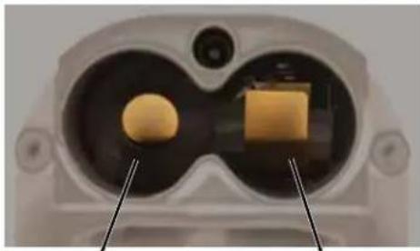
- Insert the new batteries into the housing. One battery goes in positive (+) end first, the other negative (-) end first. Look into the battery compartment to determine which end goes in which side. The side with the circular insulator is the side which accepts the positive end of the battery.
natural_image
Close-up of a medical device's internal components, showing two yellow objects and a rectangular block (no text or symbols visible)positive (+)
terminal
negative (−) terminal
Note: It is possible to install the batteries backward and close the battery door, but the batteries will not make contact and the unit will not work.
- To close the door, press it inward, flush with the housing, then slide it back into place until it snaps

natural_image
Three-step diagram showing a mechanical or structural transformation with arrows indicating direction (no text or symbols)Attaching/Removing a Microphone
The spring loaded coupler under the XLR jack maintains a secure fit to the microphone jack with continuous pressure applied by an internal spring.
To attach the microphone, simply align the XLR pins and press the microphone onto the transmitter until the coupler retracts and latches. A click sound will be heard as the connector latches.
To remove the microphone, hold the transmitter body in one hand with the microphone pointing upward. Use your other hand to rotate the coupler until the latch releases and the coupler rises slightly.
Do not pull on the microphone while releasing the locking collar.
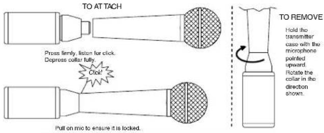
NOTE: Do not hold or apply any pressure to the microphone body while trying to remove it, as this may prevent the latch from releasing.
Operating Instructions

Power Up and Boot Sequence
1) Ensure that good batteries are installed in the unit.
2) Simultaneously press and hold the AUDIO and FREQ buttons. Continue holding the buttons until On and the characters 1, 2, 3 have appeared. The boot sequence will then initiate.

As the unit turns on, the Modulation LEDs and PWR LED all glow red, then green, and then they revert to normal operation.
The LCD displays a bootup sequence which consists of five screens:
| Category: Example | |
| Company Name: Lectro | |
| Frequency Band (XX) and Firmware Version (rX.XX): | A1 r1.00 |
| Compatibility Mode: CP 400 | |
| RF Power Output: 100 | |
| Operating Frequency 482.875 |
Power Down
Simultaneously press and hold the AUDIO and FREQ buttons. Continue holding the buttons until OFF and the countdown characters 3, 2, 1 have appeared. The unit will then power down.

If the AUDIO and FREQ buttons are released before the LCD goes blank at the end of the countdown, the unit will not turn off. Instead,
it will stay on and the LCD will return to the previous screen.
NOTE: If batteries are removed or reach the end of life while the unit is turned on, the unit will turn back on with a brief, simultaneous press of the AUDIO and FREQ buttons. The counting sequence will not be displayed in this instance.
Automatic Power Restore
The firmware will remember the power on/off state and the settings when batteries reach their end of life or are removed. When fresh batteries are installed, the unit will reboot and return to the previous settings without the need to press any buttons. This only works when the unit is fully on and transmitting. It does not work in the Standby Mode.
Standby Mode

Standby Mode allows you to verify or change the transmitter's operating frequency or audio input level without trans-
mitting a signal. Quickly press and release both the AUDIO and FREQ buttons simultaneously to enter and exit this mode. The characters rF OFF will appear on the LCD while the unit is in the standby mode.
UP Button Menu
Hold the UP button while powering up the unit.

Then press the AUDIO button repeatedly to scroll through the settings. Use the UP and DOWN arrow to select the available options under each setting.
Compatibility Mode Screen (Up Button Menu)
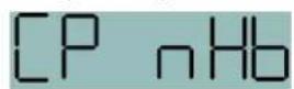
CP (Compatibility Mode); press the UP and DOWN arrows to select one of the following:
Note: RF transmission is prevented while selecting Compatibility Modes. Also, the HM exits this screen to the Standby Mode.
- nHb - For Digital Hybrid Wireless* receivers.
- 3 - (Mode 3) For non-Lectrosonics analog receivers. Contact the factory for details.
- IFB - For Lectrosonics IFB receivers.
While in the compatibility mode screen, pressing either the AUDIO or FREQ button exits to standby mode. To power off from the compatibility mode screen, press and hold AUDIO and FREQ together.
RF Power Output (Up Button Menu)
Pr (RF Power output) may be selected as:
HMa: Selectable 100 or 25 mW
HMa/E01: Selectable 25 or 50 mW
HMa/E02: 10 mW
HMa/E06: Selectable 50 or 100 mW EIRP
HMa-941: Selectable 50 or 100 mW

Selecting the Audio Polarity (Up Button Menu)

NOTE: The audio polarity can also be reversed at the output of most Lectrosonics receivers.
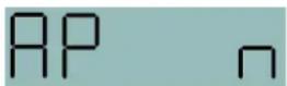
The character P denotes "positive" polarity and the character n denotes 'negative' polarity.
Selecting Step Size mode (Up Button Menu)
The frequency increments can be set at either 25 kHz or 100 kHz. Hold the UP arrow in while powering up the unit to enter the setup screen. Press the AUDIO button repeatedly to step through the setup items to reach the Step Size Mode screen. Use the UP or DOWN arrow button to select the desired setting.

DOWN Button Menu
Hold the DOWN button while powering up the unit.

Then press the AUDIO button repeatedly to scroll through the setup screens. Use the UP and DOWN arrow to select the available options for each setting.
Remote Control Enable "Dweedle Tones"
rc on allows the transmitter to respond to audio signals ("dweedle tones") delivered to the microphone from a smart phone app. rc oFF disables this function.

If a remote control signal is detected but the function is turned off, the message rc oFF will be displayed briefly on the transmitter's LCD to confirm that a valid signal was received, but that the remote control function is not enabled.
HMa transmitter settings that can be adjusted:
• Audio input level (gain)
- Operating frequency
- Panel Lock/Unlock
- RF power output
- Low frequency roll-off filter
- Power LED on/off
The LectroRM Smart Phone App is used almost exclusively for remote control. See the section entitled Remote 'Control with Dweedle Tones on page 12 for more information.
Power Back On (DOWN Button Menu)
PbAc (Power back on after power loss) sets the unit to either (1) turn back on after power loss or (0) remain off.

LCD Backlight Setting (Down Button Menu)
The LCD backlight can be set to turn off after either 5 minutes or 30 seconds or stay on continuously. Hold the DOWN arrow in while powering up the unit to enter the setup screen. Press the AUDIO button repeatedly to step through the setup items to reach the backlight settings screen. Use the UP or DOWN arrow button to select the desired setting.


Band/Legacy Block 606 Setting (Down Button Menu)
Allows access to either the full B1, B2 or C1 band or only Block 606. When using a a Block 606 receiver such as an SRb/E01-606 or a UCR411a-606, the pilot tones must match for the receiver to recognize the signal from the transsitter. Press and hold the DOWN arrow button then press the AUDIO button to access.
Available only for E01 models.

AUDIO Button Settings
Aud 12 Press the AUDIO button repeatedly to select the setting. Each time the button is released, the screen will switch to the next setting. Press and hold the button when the desired setting appears on the screen, then use the UP and DOWN arrow buttons to adjust the setting.
Adjusting the Input Gain
Rud 12 The control panel Modulation LEDs indicate the modulation level and limiter activity. This
gain adjustment matches the transmitter gain with the microphone's output level, the user's voice level and the position of the microphone. Once set, the transmitter's audio level setting should not be used to control the volume of your sound system or recorder levels. The audio input level can be set with the unit in Stand-by Mode or while powered up in normal operation.
Signal Level -20 LED -10 LED
| Less than -20 dB | Off | Off |  |
| -20 dB to -10 dB | Green |  | |
| -10 dB to +0 dB | Green |  | |
| +0 dB to +10 dB | Red | Gre |  |
| Greater than +10 dB | Red |  |
Note: Voice levels vary significantly between different people. If several different people will be using the transmitter and there is not time to make the adjustment for each individual, adjust it for the loudest voice.
1) With the HMa powered off, insert the microphone plug into the XLR Input Jack, aligning the pins and ensuring that the connector locks.
2) Place the transmitter in the Standby Mode, or if the unit is to be powered up and adjusted, mute the main sound system prior to powering up the transmitter.
3) Position the microphone in the location where it will be used in actual operation.
4) Observe the audio level LEDs while speaking or singing into the microphone at the same voice level that will be used during use. While holding the AUDIO button, press the UP or DOWN arrows until the both the -20 and -10 LEDs glow green, with the -20 LED flickering red on louder peaks. This will optimize the signal to noise ratio of the system with full modulation and adequate headroom to prevent overload and audible compression of signal peaks.
Note: Setting the audio level too high reduces the dynamic range of the audio signal. Setting the audio level too low may cause hiss and noise in the audio.
5) If the unit was set up in Standby Mode, it will be necessary to turn the transmitter off, then power it up again in normal operation so the RF output will be on. Then the other components in the sound or recording system can be adjusted.
Adjusting the Low Frequency Roll-off

The roll-off frequency can be set to 35, 50, 70, 100, 120 or 150 Hz.
This setting is often made while listening to the audio while selecting the setting.
Selecting the Phantom Power Supply

The transmitter input jack can provide phantom power for the attached microphone if needed, with voltages at 5, 15 or 48. Phantom power will consume a slight amount of battery power, so it can also be turned off.
Selecting the Phantom Power Supply (Audio Screen Menu)
The transmitter input jack can provide phantom power for the attached microphone if needed, with voltages at 5, 15 or 48. Phantom power will consume a slight amount of battery power, so it can also be turned off.
With the transmitter powered on and in the normal or standby mode, press and hold the audio button and observe the LCD. Release the button and press and hold it again. Repeat this process until the display indicates the PH.

Once you get to the PH setting, keep the AUDIO button pressed, then use the UP and DOWN arrow keys to cycle through the available settings (off, 5, 15, 48 volts) until the desired setting is displayed.

When you release the AUDIO button, the setting will be stored to the value you selected.
About the Phantom Power Supply
Three phantom voltages are selectable from the control panel. The voltages are:
- 5 Volts for lavaliere microphones,
- 15 Volts for some professional mics requiring high current and for many common stage mics that will operate over a wide phantom Voltage range of 12 to 48 Volts. With the proper adapter, this position can also be used with T power microphones. See our web site for details on finding or making the proper adapter.
- 48 Volts for microphones that do in fact require a supply greater than 18 Volts. (See following for a discussion of why 42 and not a “true” 48 Volts.)
For longest battery life use the minimum phantom voltage necessary for the microphone. Many stage microphones regulate the 48 Volts down to 10 Volts internally anyway, so you might as well use the 15 Volt setting and save some battery power. If you are not using a microphone for the input device, or are using a microphone that does not require phantom power, turn the phantom power off.
Phantom power should only be used with a fully floating, balanced device such as most microphones with a 3-pin XLR connector. If you use the phantom power with an unbalanced device or if pins 2 or 3 are DC connected to ground, then you will draw maximum current from the power supply. The HM is fully protected against such shorts but the batteries will be drained at twice the normal rate.
The transmitter can supply 4 mA at 42 Volts, 8 mA at 15 Volts, and 8 mA at 5 Volts. The 42 Volts setting actually supplies the same voltage to a 48 Volt microphone as the DIN standard arrangement due to a dynamic biasing scheme that does not have as much voltage drop as the DIN standard. The 48 Volt DIN standard arrangement protects against shorts and high fault current with high resistance in the power supply feeds to pins 2 and 3. This provides protection if the supply current is accidentally shorted to ground and also keeps the microphone from being attenuated by the power supply.
The HMa improves on those functions and is able to use less power from the battery by using constant current sources and current limiters. With this dynamic arrangement the HMa can also supply more than twice the current of competing 48 Volt plug on units and provide four times the current for some very high end 15 Volt microphones.
FREQ Button Settings
Press the FREQ button on the Control Panel to enter this setup screen. The display will vary depending upon which StepSize setting is selected. See Selecting Step Size on page 9.
Note: The default display is in MHz. Pressing the FREQ button again displays the operating frequency as a two-digit hexadecimal number that corresponds to legacy Lectrosonics products that used two 16-position switches to set the frequency.
While holding the FREQ button, use the UP or DOWN arrow buttons to change the frequency.
Note: The operating frequency displayed on the LCD wraps as it reaches the upper or lower end of its range.
Block 470/19 Frequency Overlap

bar_stacked
| Block | Frequency Overlap (Left) | Frequency Overlap (Right) | | :--- | :--- | :--- | | Block 470 | 470.1 - 495.6 | | | Block 19 | 486.4 - 511.9 | |Frequencies 486.400 - 495.600 Overlap in Blocks 470 and 19
Block 470 and block 19 overlap each other in the frequency range from 486.400 to 495.600 MHz. Since block 470 starts at a lower frequency than block 19, the hex codes (and pilot tones) will not match even though the frequencies are the same in the overlap zone. When using a transmitter on the A1 band with a block 19 receiver, be sure the transmitter is set to block 19 and check the hex code on the receiver to make sure it matches the transmitter.
Call the factory for further questions on this issue.
Set Up in 100kHz Step Size

Frequency displayed in MHz

Frequency displayed as two-digit hexadecimal number
The operating frequency can be displayed either in MHz or as a two-digit hexadecimal number. The example of the two-digit display shown here indicates CH (channel) and 2C as the frequency.
The frequency can be set with the unit in standby mode or when powered up for normal operation.
Set Up in 25kHz Step Size
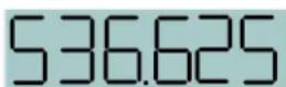
Frequency expressed in MHz
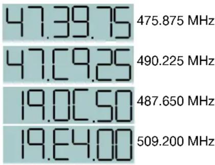
The hexadecimal display in the 25 kHz mode will appear with a decimal suffix to indicate the 25 kHz steps.

Examples:
other
| Frequency (MHz) | Value | |---|---| | 475.875 | 47.39.75 | | 490.225 | 47.09.25 | | 487.650 | 19.00.50 | | 509.200 | 19.64.00 |Lock/Unlock Screen
Simultaneously pressing and holding both the UP and DOWN arrow buttons during normal operation starts the LOCK timer. The timer starts at three and counts down to zero. When the timer reaches zero, the keypad controls are locked.
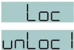
The LCD will display the locked condition as long as the arrow buttons are held, then revert back to the previous screen when either button is released.
With the controls locked, the AUDIO and FREQ buttons can still be used to display current settings. Any attempt to change a setting by pressing either the UP or DOWN arrow button will result in an on-screen Loc reminder that the controls are locked.
NOTE: The control panel can be unlocked by removing the batteries or using the "dweedle" tone remote control.
Remote Control with "Dweedle Tones"
Various settings on the transmitter can be adjusted with special audio tones (“dweedle tones”) delivered to the microphone. The tones are generated by a smart phone using the LectroRM app.
LectroRM is a third party application written by New Endian for iOS and Android smart phones that generates the control tones for the remote control functions. The app is available for purchase from the App Store or Google Play for about \$20.
HMa transmitter settings that can be adjusted:
• Audio input level (gain)
- Operating frequency
- Panel Lock/Unlock
- RF power output
- Low frequency roll-off filter
- Power LED on/off
Enable the remote control function by holding the DOWN arrow then pressing the AUDIO and FREQ buttons at the same time. Use the arrow buttons to select on to enable the function, or oFF to disable the function.

If a remote control signal is detected but the function is turned off, the message rc oFF will be displayed briefly on the transmitter's LCD to confirm that a valid signal was received, but that the control function is not enabled. If a remote control setting is delivered to the transmitter that is not available, such as SLEEP/UN-SLEEP in the HMa, the display on the transmitter will show - - - - - and then return to the previous screen.
The usable distance between the microphone and the smart phone will vary with the input gain setting on the transmitter and the volume control setting on the Smartphone.
NOTE: Any microphone/transmitter within range of the Smartphone will "hear" and execute the remote control command. Be careful to make sure only the desired microphone/transmitter is within range when delivering the audio tone.
LectroRM
By New Endian LLC
LectroRM is a mobile application for iOS and Android operating systems. Its purpose is to remotely control Lectrosonics Transmitters, including:
- SM Series
• WM - L Series
- HMa, HMa/E01
The app remotely changes settings on the transmitter through the use of encoded audio tones, which when received by the attached microphone, will alter the configured setting. The app was released by New Endian, LLC in September 2011. The app is available for download and sells for \$25 on the Apple App Store and Google Play Store.
LectroRM's remote control mechanism is the use of an audio sequence of tones (dweedles) that are interpreted by the transmitter as a configuration change. The settings available in LectroRM are:
- Audio Level
- Frequency
- Sleep Mode
- Lock Mode
User Interface
The user interface involves selecting the audio sequence related to the desired change. Each version has an interface for selecting the desired setting and the desired option for that setting. Each version also has a mechanism to prevent accidental activation of the tone.
iOS

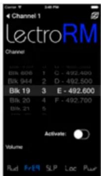
The iPhone version keeps each available setting on a separate page with the list of options for that setting. On iOS, the "Activate" toggle switch must be enabled to show the button which will then activate the audio. The iOS version's default orientation is upside-down but can be configured to orient right-side up. The purpose for this is to orient the device's speaker, which is at the bottom of the device, closer to the transmitter microphone.
Android


The Android version keeps all settings on the same page and allows the user to toggle between the activation buttons for each setting. The activation button must be long pressed to activate. The Android version also allows users to keep a configurable list of full sets of settings.
Activation
For a transmitter to respond to remote control audio tones, the transmitter must meet certain requirements:
- The transmitter must not be turned off; it can however be in sleep mode.
- The transmitter must have firmware version 1.5 or later for Audio, Frequency, Sleep and Lock changes.
- The transmitter microphone must be within range.
- The transmitter must be configured to enable remote control activation.
Please be aware this app is not a Lectrosonics product. It is privately owned and operated by New Endian LLC, www.newendian.com.
Supplied Accessories
PHTRAN3
Replacement leather pouch with clear plastic screen cover, rotating belt clip and snap closure. Included with transmitter at purchase.

40096 Alkaline Batteries (2)

natural_image
Two cylindrical batteries with red and brown casing, no visible text or markingsOptional Accessories
21750 Barrel Adapter

natural_image
Metallic cylindrical connector with four pins, no visible text or symbolsMic adapter for Earthworks M30 microphone with HM, HMa and UH400a/TM transmitters.
This polarity reversing adapter may be needed to correct for asymmetrical current draw in some P48 powered condenser microphones, including older Neumann 100 Series, Rode NTG3 and others. If your microphone does not power on correctly when used with these transmitters, insert the adapter between the transmitter and microphone.
MCA-M30 Barrel Adapter

natural_image
Close-up of a metallic MCA-M20 connector with three pins (no visible text or symbols beyond branding)
This adapter may be needed if you are experiencing noise or distortion with measurement microphones, particularly the Earthworks M30. The adapter has a common mode choke for suppressing RF noise. If your microphone signal exhibits the problems listed above when connected to a UH400, HM or HMa transmitter, insert the adapter between the microphone and the transmitter.
Insert the adapter between the transmitter and microphone to alleviate the problems listed above.
MCA5X
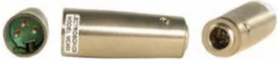
Optional adapter for connecting a lavaliere microphone to the HMa or HM transmitters. TA5M to XLR3-M connectors. Passes transmitter phantom power to bias the electret lavaliere microphone. Includes zener protection to limit bias voltage to protect the microphone if transmitter phantom power is set too high.
natural_image
Three views of a cylindrical electronic component with visible internal structure and green circuit board (no text or symbols)MCA-TPOWER
This cable adapter is to be used with the UH200D, UH400, HM and HMa plug-on transmitters with T-powered microphones. It will protect a T-power mic against the 48V phantom power setting in the transmitter while allowing normal operation. The transmitter should be set to the 15V position for best operation and minimum battery drain.

natural_image
Close-up of two metallic USB connectors attached to a coiled cable (no text or symbols visible)HMCVR/HMCVR-BLK
These tough white silicone covers protect transmitters from moisture and dust. The pliable material and the two-part design make the covers easy to install and remove. By customer request, we also offer these covers in opaque matte black. Ideal for television broadcast, stage or other high-profile visual applications where a seamless and sleek appearance is desired.

natural_image
Two black plastic bottle containers, one with dotted pattern and the other with tapered cap (no text or symbols visible)Specifications and Features
Operating Frequency Range:
| HMa: | Band A1: | 470.100 - 537.575 |
| Band B1: | 537.600 - 607.950 | |
| HMa/X: | Band A1: | 470.100 - 537.575 |
| Band B1: | 537.600 - 614.375 | |
| Band C1: | 614.400 - 691.175 | |
| HMa/E01: | Band A1: | 470.100 - 537.575 |
| Band B1: | 537.600 - 614.375 |
| Band 606: | 606.000 - 631.500 |
| Band B2: | 563.200 - 639.900 |
| Band C1: | 614.400 - 691.175 |
| HMa/E02: | Band A1: | 470.100 - 537.575 |
| Band B1: | 537.600 - 614.375 | |
| Band C1: | 614.400 - 691.175 | |
| Band C2: | 640.000 - 713.900 |
| HMa/E06: | Band B1: | 537.600 - 614.375 |
| Band C1: | 614.400 - 691.175 |
| HMa-941: | 941.525 - 951.975 |
| 952.875 - 956.225 | |
| 956.475 - 959.825 |
| HMa/E07-941: | 941.525 - 951.975 |
| 953.025 - 956.225 | |
| 956.475 - 959.825 |
NOTE: It's the user's responsibility to select the approved frequencies for the region where the transmitter is operating
| Frequency Selection Steps: | Selectable; 100 kHz or 25 kHz |
| RF Power output: | HMa: Selectable 100 or 50 mWHMa/E01: Selectable 25 or 50HMa/E02: 10 mWHMa/E06: Selectable 50 |
or 100 mW EIRP
HMa/E07-941: Selectable 50 or 100 mW
HMa-941: Selectable 50 or 100 mW
Compatibility Modes: HMa: Nu Hybrid, Mode 3, IFB Mode
HMa/E01: Digital Hybrid, Mode 3, IFB Mode
HMa/E02: Digital Hybrid, Mode 3, IFB Mode
HMa/E06: Digital Hybrid, Mode 3, IFB Mode
HMa/E07-941, HMa-941: Nu Hybrid, IFB Mode
HMa/X: Digital Hybrid, Mode 3, 200 Mode, 100 Mode, Mode 7, Mode 6, IFB Mode
| Pilot tone: (in the Digital Hybrid mode) | 25 to 32 kHz; 5 kHz deviation |
Frequency stability: ± 0.002%
| Spurious radiation: | HMa/E01/E02/941/X: |
| 60 dB below carrier |
| HMa: Compliant with ETSI EN 300 422-1 v1.4.2 |
Equivalent input noise: -125 dBV (A-weighted)
| Input level: | Nominal 2 mV to 300 mV, before limiting. |
| Greater than 1V maximum, with limiting. | |
Input impedance: 1K Ohm
| Input limiter:than 30 dB range | Dual envelope "soft" limiter; greater |
| Gain control range:membrane switches | 55 dB; panel mounted |
| Operating temp. range: Celsius: | -20° - 40° |
| Farenheit: -5° - 104° |
| Modulation indicators: Dual bi-color LEDs indicate modulation of -20, -10, 0, +10 dB referenced to full modulation |
Audio Performance (overall system):
Frequency Response: 35 Hz to 20 kHz (+/-1dB);
Low frequency Roll-off: Adjustable for -3dB @30, 50, 70, 100, 120 or 150 Hz)
THD: 0.2% (typ. 100 Hz to 20 kHz - see table)
Signal to Noise Ratio (dB) at receiver output:
| SmartNR | no limiting | w/limiting |
| OFF | 103.5 | 108.0 |
| NORMAL | 107.0 | 111.5 |
| FULL | 108.5 | 113.0 |
Note: The dual envelope "soft" limiter provides exceptionally good handling of transients using variable attack and release time constants. Once activated, the limiter compresses 30+ dB of transmitter input range into 4.5 dB of receiver output range, thus reducing the measured figure for SNR without limiting by 4.5 dB.
Input Dynamic Range: 125 dB (with full Tx limiting)
Controls & Indicators: • Power/Phantom "ON-OFF"
- Phantom voltage selector
- Audio input gain
• LCD w/membrane switches
• LED audio level indicators
Audio Input Jack: Standard 3-pin XLR (female)
Phantom Power: 5V @ 18 mA max., 15V @ 15 mA max. and 48 V @ 4 mA max., plus "OFF"
USB port: Used for firmware updates
IR (infrared) port: For quick setup by transferring settings from an IR enabled receiver
Antenna: Housing and attached microphone form the antenna
Battery: Two 1.5 Volt AA alkaline
Battery Life (Duracell Ultra):
AA alkaline; No Phantom Power: 5h 0m*
AA alkaline; 48V Phantom Power: 3h 30m**
* Tested with a dynamic microphone
** Tested with a Sanken CS1 for a phantom-powered microphone
Weight: 6.7 oz (190 grams) without batteries
Dimensions: 4.25x1.62x1.38 inches 107.95x41.15x35.05 mm
Emission Designator: A1: 44K3F3E B2: 57K9F3E HMa/E06: 180KF3E HMa/E07-941: 110KF3E
Specifications subject to change without notice.
CE UK CA
Firmware Update
Updating the firmware is a simple matter of downloading a utility program and file from the website and running the program on either a Windows or Mac operating system with the transmitter connected to a computer via the USB port.
Go to www.lectrosonics.com. In the top menu, hover the mouse over Support, then click on Firmware. Choose your product (HMa) from the list, then review the Firmware Revision History to determine the Update that you need.
Step 1:
Begin by downloading the USB Firmware Updater Program.
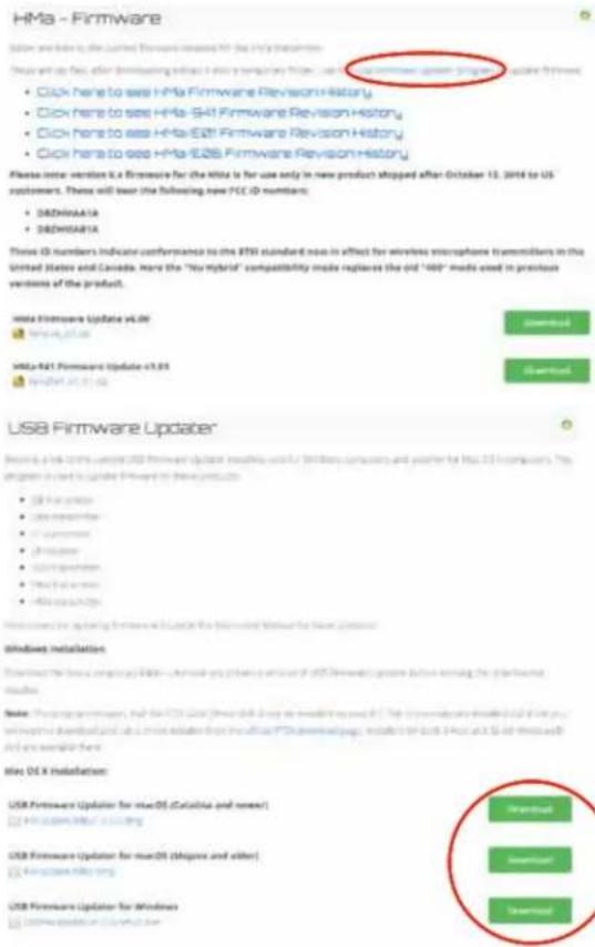

Step 2:

Next, test the Updater by opening the icon: If the driver opens automatically, proceed to Step 3.
WARNING: If you receive the following error, the Updater is not installed on your system. Follow the TROUBLESHOOTING steps to fix the error.

TROUBLESHOOTING:
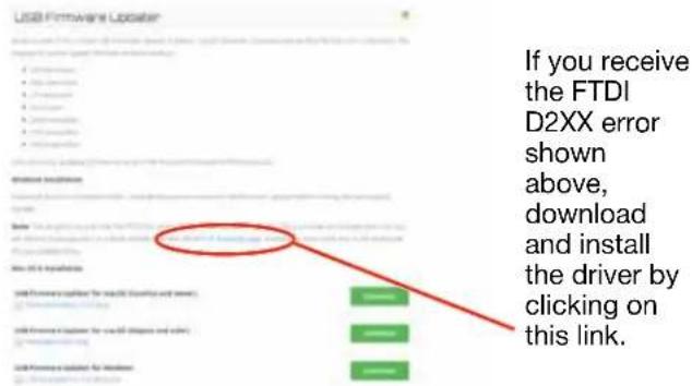
Then click here to download.
NOTE: This website, http://www.ftdichip.com/ Drivers/D2XX.htm, is not associated with Lectrosonics.com. It is a third party site used only for D2XX drivers currently available for Lectrosonics' devices' upgrades.

Step 3:
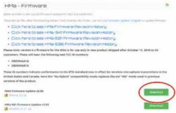
Refer to Step 1 to return to Firmware web page. Download Firmware Update and save to a local file on your PC for easy locating when updating.
Step 4:
Open Lectrosonics USB Firmware Updater.


Step 5:

With the unit powered OFF, put the transmitter in UPDATE mode by simultaneously holding down the UP arrow, DOWN arrow, AUDIO and FREQ buttons.
Step 6:
Using a microUSB cable, connect the transmitter to your PC.
Step 7:
In Lectrosonics USB Firmware Updater, choose the detected device, browse to local Firmware File and click Start.
NOTE: It may take up to a minute or so for the Updater to recognize the transmitter.
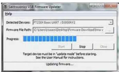
WARNING: Do not disrupt the microUSB cable during updating.
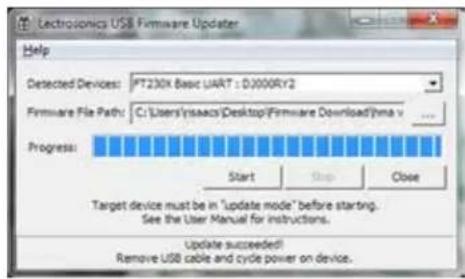
The Updater alerts with progress and completion.
Step 8:
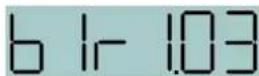
Once the Updater has completed, turn off the transmitter, then turn it back on to verify that the firmware version on the transmitter LCD matches the firmware version shown on the web site. The firmware is the second LCD display during bootup sequence.
Step 9:
Close Updater and disconnect microUSB cable.
Troubleshooting
Before going through the following chart, be sure that you have good batteries in the transmitter. It is important that you follow these steps in the sequence listed.
SYMPTOM POSSIBLE CAUSE
TRANSMITTER PWR LED OFF 1) Batteries are inserted backwards or dead.
2) Transmitter not powered up. (See Operating Instructions, Power UP and Boot Sequence.)
AUDIO LEVEL LEDs NOT LIGHTING 1) Gain control set to minimum.
2) Batteries are inserted backwards or dead. Check PWR LED.
3) Mic capsule is damaged or malfunctioning.
4) Mic connector is damaged or mis-wired.
RECEIVER RF INDICATOR OFF 1) Transmitter not turned on, or is in Standby Mode.
2) Transmitter batteries are dead.
3) Receiver antenna missing or improperly positioned.
4) Transmitter and receiver not on same frequency. Check switches/display on transmitter and receiver.
5) Transmitter and receiver not on same frequency band.
6) Operating range is too great.
NO SOUND (OR LOW SOUND LEVEL), RECEIVER INDICATES PROPER AUDIO MODULATION
1) Receiver output level set too low.
2) Receiver output disconnected, or cable defective or mis-wired.
3) Sound system or recorder input is turned down.
DISTORTED SOUND 1) Transmitter gain (audio level) is far too high. Check audio level LEDs and receiver audio levels during use.
2) Receiver output may be mismatched with the sound system or recorder input. Adjust output level on receiver to the correct level for the recorder, mixer or sound system. (Use the receiver's Tone function to check level.)
3) Excessive wind noise or breath "pops." Reposition microphone and/or use a larger windscreen.
4) Transmitter is not set to same frequency as receiver. Check that
operating frequency on receiver and transmitter match.
5) Receiver/Transmitter Compatibility Mode mismatched.
EXCESSIVE FEEDBACK 1) Transmitter gain (audio level) too high. Check gain adjustment and/or reduce receiver output level.
2) Talent standing too close to speaker system.
3) Mic is too far from user's mouth.
SYMPTOM POSSIBLE CAUSE
HISS AND NOISE -- AUDIBLE DROPOUTS 1) Transmitter gain (audio level) far too low.
2) Receiver antenna missing or obstructed.
3) Operating range too great.
4) Signal interference. Turn off transmitter. If receiver's signal strength indicator does not drop to nearly zero, this indicates an interfering signal may be the problem.
Use a clear operating frequency.
"Loc" APPEARS IN DISPLAY WHEN ANY BUTTON IS PRESSED
1) Control Panel is locked. (See Operating Instructions, Locking
and Unlocking the Control Panel.)
"Hold" APPEARS IN DISPLAY WHEN ARROW BUTTONS ARE PRESSED
Reminder that it is necessary to hold down the AUDIO or FREQ button to make adjustments to the audio gain or frequency settings.
"PLL" APPEARS IN DISPLAY
Indication that the PLL is not locked. This is a serious condition
that requires factory repair. It may be possible to operate on another frequency far removed from the one that was selected when the unlocked condition was indicated.
Service and Repair
If your system malfunctions, you should attempt to correct or isolate the trouble before concluding that the equipment needs repair. Make sure you have followed the setup procedure and operating instructions. Check the interconnecting cables and then go through the Troubleshooting section in this manual.
We strongly recommend that you do not try to repair the equipment yourself and do not have the local repair shop attempt anything other than the simplest repair. If the repair is more complicated than a broken wire or loose connection, send the unit to the factory for repair and service. Don't attempt to adjust any controls inside the units. Once set at the factory, the various controls and trimmers do not drift with age or vibration and never require readjustment. There are no adjustments inside that will make a malfunctioning unit start working.
LECTROSONICS' Service Department is equipped and staffed to quickly repair your equipment. In warranty repairs are made at no charge in accordance with the terms of the warranty. Out-of-warranty repairs are charged at a modest flat rate plus parts and shipping. Since it takes almost as much time and effort to determine what is wrong as it does to make the repair, there is a charge for an exact quotation. We will be happy to quote approximate charges by phone for out-of-warranty repairs.
Returning Units for Repair
For timely service, please follow the steps below:
A. DO NOT return equipment to the factory for repair without first contacting us by email or by phone. We need to know the nature of the problem, the model number and the serial number of the equipment. We also need a phone number where you can be reached 8 A.M. to 4 P.M. (U.S. Mountain Standard Time).
B. After receiving your request, we will issue you a return authorization number (R.A.). This number will help speed your repair through our receiving and repair departments. The return authorization number must be clearly shown on the outside of the shipping container.
C. Pack the equipment carefully and ship to us, shipping costs prepaid. If necessary, we can provide you with the proper packing materials. UPS is usually the best way to ship the units. Heavy units should be "double-boxed" for safe transport.
D. We also strongly recommend that you insure the equipment, since we cannot be responsible for loss of or damage to equipment that you ship. Of course, we insure the equipment when we ship it back to you.
Lectrosonics USA:
Mailing address: Shipping address: Telephone:
Lectrosonics, Inc. Lectrosonics, Inc. (505) 892-4501
PO Box 15900 561 Laser Rd., Suite 102 (800) 821-1121 Toll-free
Rio Rancho, NM 87174 Rio Rancho, NM 87124 (505) 892-6243 Fax
USA USA
Web: E-mail:
www.lectrosonics.com sales@lectrosonics.com
Lectrosonics Canada:
| Mailing Address: | Telephone: | E-mail: | ||
| 720 Spadina Avenue, Suite 600 (877) 753-2876 Toronto, Ontario M5S 2T9 | (416) 596-2202 | Sales: joeb@lectrosonics.com | colinb@lectrosonics.com | |
| Toll-free (877-7LECTRO) | ||||
| (416) 596-6648 | Fax | |||
Self-Help Options for Non-Urgent Concerns
Our Facebook groups and weblists are a wealth of knowledge for user questions and information. Refer to:
Lectrosonics General Facebook Group: https://www.facebook.com/groups/69511015699
D Squared, Venue 2 and Wireless Designer Group: https://www.facebook.com/groups/104052953321109
The Wire Lists: https://lectrosonics.com/the-wire-lists.html
EU Declaration of Conformity

P.O. Box 15900 - Rio Rancho, NM - 87174 - USA
Phone: (800)821-1121 or (505)892-4501 - Fax: (505)892-6243
web: www.lectrosonics.com - email: sales@lectrosonics.com
EU Declaration of Conformity
LECTROSONICS, INC.
581 Laser Road
Rio Rancho, NM 87124 USA
Declares under our sole responsibility that the following product:
Model: HMA/E01-A1, HMA/E01-B1, HMA/E01-C1
Wireless microphone transmitter
is in conformity with the provisions of the following EC directive(s) (including applicable amendments) and are designed and manufactured in accordance with the harmonized standards:
| Document | Description | Date/Version |
| RL 2014/53/EU | Radio Equipment Directive 2014/53/EU (RED) | 2014-04 |
| EN 300 422-1 | Wireless Microphones; Audio PMSE up to 3 GHz; Part 1: Class A Receivers | V1.4.1(2015-06) |
| Electromagnetic Compatibility | ||
| EN 301 489-1 | ElectroMagnetic Compatibility (EMC) standard for radio equipment and services; Common Technical Requirements | V1.9.2(2011-09) |
| EN 301 489-9 | Specific Conditions for wireless microphones, similar Radio Frequency (RF) audio link equipment, cordless audio and in-ear monitoring devices | V1.4.1(2007-11) |
| Safety and Health | ||
| EN 62368-1 | Audio/video and communications technology equipment – Safety Requirements | 2014+A11:2017 |
| EN 62311 | Assessment of electronic and electrical equipment related to human exposure restrictions for electromagnetic fields (0 Hz – 300 GHz) | 2008 |
| RL 2011/65/EU | RoHS Directive 2011/65/EU: Restriction of the use of certain hazardous substances (RoHS Recast) | 2011 |
ISEDC Notices:
Per RSS-210
This device operates on a no-protection no-interference basis. Should the user seek to obtain protection from other radio services operating in the same TV bands, a radio licence is required. Please consult Industry Canada's document CPC-2-1-28, Optional Licensing for Low-Power Radio Apparatus in the TV Bands, for details.
This device complies with Industry Canada's license-exempt RSSs. Operation is subject to the following two conditions:
1) This device may not cause interference
2) This device must accept any interference, including interference that may cause undesired operation of the device.
This device complies with part 15 of the FCC Rules. Operation is subject to the following two conditions: (1) This device may not cause harmful interference, and (2) this device must accept any interference received, including interference that may cause undesired operation.
FCC Notice:
For body worn operation, this transmitter model has been tested and meets the FCC RF exposure guidelines when used with the Lectrosonics accessories supplied or designated for this product. Use of other accessories may not ensure compliance with FCC RF exposure guidelines. Contact Lectrosonics if you have any questions or need more information about RF exposure using this product.
FCC Compliance:
This device complies with FCC radiation exposure limits as set forth for an uncontrolled environment. This device should be installed and operated so that its antenna(s) are not co-located or operating in conjunction with any other antenna or transmitter.
Industry Canada Compliance:
This device operates on a no-protection no-interference basis. Should the user seek to obtain protection from other radio services operating in the same TV bands, a radio license is required. Please consult Industry Canada's document CPC-2-1-28, Optional Licensing for Low-Power Radio Apparatus in the TV Bands, for details.
This device complies with Industry Canada license-exempt RSS standard(s). Operation is subject to the following two conditions:
- This device may not cause harmful interference;
- This device must accept any interference received, including interference that may cause undesired operation of the device.
The equipment is warranted for one year from date of purchase against defects in materials or workmanship provided it was purchased from an authorized dealer. This warranty does not cover equipment which has been abused or damaged by careless handling or shipping. This warranty does not apply to used or demonstrator equipment.
Should any defect develop, Lectrosonics, Inc. will, at our option, repair or replace any defective parts without charge for either parts or labor. If Lectrosonics, Inc. cannot correct the defect in your equipment, it will be replaced at no charge with a similar new item. Lectrosonics, Inc. will pay for the cost of returning your equipment to you.
This warranty applies only to items returned to Lectrosonics, Inc. or an authorized dealer, shipping costs prepaid, within one year from the date of purchase.
This Limited Warranty is governed by the laws of the State of New Mexico. It states the entire liability of Lectrosonics Inc. and the entire remedy of the purchaser for any breach of warranty as outlined above. NEITHER LECTROSONICS, INC. NOR ANYONE INVOLVED IN THE PRODUCTION OR DELIVERY OF THE EQUIPMENT SHALL BE LIABLE FOR ANY INDIRECT, SPECIAL, PUNITIVE, CONSEQUENTIAL, OR INCIDENTAL DAMAGES ARISING OUT OF THE USE OR INABILITY TO USE THIS EQUIPMENT EVEN IF LECTROSONICS, INC. HAS BEEN ADVISED OF THE POSSIBILITY OF SUCH DAMAGES. IN NO EVENT SHALL THE LIABILITY OF LECTROSONICS, INC. EXCEED THE PURCHASE PRICE OF ANY DEFECTIVE EQUIPMENT.
This warranty gives you specific legal rights. You may have additional legal rights which vary from state to state.
- CE UK CA
- Table of Contents
- FCC Compliance:
- General Technical Description
- Digital Hybrid Wireless® Technology
- No Pre-Emphasis/De-Emphasis
- Low Frequency Roll-Off
- Input Limiter
- Signal Encoding and Pilot Tone
- Microprocessor and DSP
- Compatibility Modes
- Control Panel
- Controls and Functions
- LCD Screen
- Power LED
- Audio Input Jack
- Battery Compartment
- USB Port
- IR Port
- Modulation LEDs
- Audio Button
- Freq Button
- UP/DOWN Arrows and Panel Lockout
- Antenna
- Battery Installation
- Attaching/Removing a Microphone
- Operating Instructions
- Power Up and Boot Sequence
- Power Down
- Automatic Power Restore
- Standby Mode
- UP Button Menu
- Compatibility Mode Screen (Up Button Menu)
- RF Power Output (Up Button Menu)
- Selecting Step Size mode (Up Button Menu)
- Remote Control Enable "Dweedle Tones"
- Power Back On (DOWN Button Menu)
- LCD Backlight Setting (Down Button Menu)
- Band/Legacy Block 606 Setting (Down Button Menu)
- AUDIO Button Settings
- Adjusting the Input Gain
- Adjusting the Low Frequency Roll-off
- Selecting the Phantom Power Supply
- Selecting the Phantom Power Supply (Audio Screen Menu)
- About the Phantom Power Supply
- FREQ Button Settings
- Lock/Unlock Screen
- Remote Control with "Dweedle Tones"
- LectroRM
- By New Endian LLC
- User Interface
- Activation
- Supplied Accessories
- PHTRAN3
- Optional Accessories
- MCA5X
- MCA-TPOWER
- HMCVR/HMCVR-BLK
- Specifications and Features
- NOTE: It's the user's responsibility to select the approved frequencies for the region where the transmitter is operating
- Firmware Update
- Step 1:
- Step 2:
- TROUBLESHOOTING:
- Step 3:
- Step 4:
- Step 5:
- Step 6:
- Step 7:
- Step 8:
- Step 9:
- Troubleshooting
- SYMPTOM POSSIBLE CAUSE
- Service and Repair
- Returning Units for Repair
- Lectrosonics USA:
- Mailing address: Shipping address: Telephone:
- Web: E-mail:
- Self-Help Options for Non-Urgent Concerns
- EU Declaration of Conformity
- ISEDC Notices:
- Per RSS-210
- FCC Notice:
- Industry Canada Compliance:
Brand : Lectrosonics
Model : HMa/E06
Category : Wireless audio transmitter